

Operation Manual
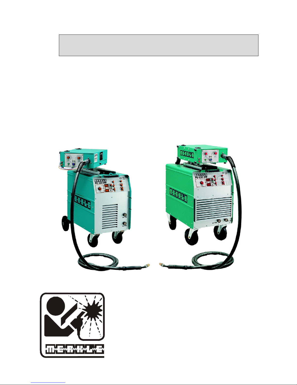
Synergic Pulse Welding Unit
Model PU 400 DW
Model PU 520 DW
MERKLE
Schweissanlagen-Technik GmbH
Industriestrasse 3
D-89359 Koetz,
Germany
Tel.: ++49-8221-915-0
Fax: ++49-8221-915-40
www.merkle.de

.

Content page
1 Security indications before introduction 3
2 Accident prevention regulations 3
2.1
3 Duty cycle 5
4 Instructions to avoid interferences due to electromagnetic influences EMC 5
5 Technical Data: 7
6 Start Up 8
6.1 Installation of the Machine 8
6.2 Main Supply 8
6.3 Welding Torch 8
6.4 Gas Connection 8
6.5 Wire Installation 8
6.6 Earth Lead (Work Cable) 8
Safety instructions 3
6.7 Transport 9
7 Generalities of the welding unit 9
7.1 Model PU 400 DW / PU520 DW 9
7.2 Cooling of the power modul 9
7.3 Electronics 9
7.4 TEDAC-System 9
8 The indicated numbers below are refering to the drawing of the front panel 11
9 Operation of the Unit PU 400 / 520 DW 11
9.1 Switching on the machine 11
9.2 Selection of the welding process 12
9.3 Setting of the welding energy 12
9.4 Setting of the operation mode 12
9.5 Safety cut off 14
9.6 Adjusting of 'start current', 'down slope' time, 'final current' and 'intermission' time 14
10 Activation of the fixed TEDAC programs (jobs) 15
10.1 Generating your own TEDAC program 15
1

11 Pulse-Arc Welding Units PU 400 DW and PU 520 DW 16
11.1 Advantages – Point by point 16
11.2 Construction of the housing: 17
11.3 Locking of the control panel 17
12 Cleaning 18
13 Maintenance and Accident Prevention 18
14 Trouble Shooting 18
14.1 Machine does not operate after switching on the main switch 18
14.2 Machine does not react on the torch switch 18
14.3 Machine has no or too low welding current 18
14.4 Welding quality is not good 19
14.5 Problems with wire feeding and wire contacting 19
15 Aluminium Welding 19
16 Wire feeder systems 20
16.1 Spare parts wire feeder model: DV-25 22
16.2 Spare parts wire feeder model: DV-30 25
17 Torches - and Spare parts 29
17.1 MIG-MAG-welding torch model SB/SBT 502 W 29
17.2 Push-Pull-welding torch model PP/PPT 502 W 34
18 Stored programs PU 400 39
19 Spare parts and wiring diagram 40
19.1 Spare part list PU 400 DW 40
19.2 wiring diagram PU 400 41
19.3 Spare Part List PU 520 DW 49
19.4 wiring diagram PU 520 50
20 Stored programs PU 520 57
21 EU-Conformity Attestation PU 400 DW 59
22 EU-Conformity Attestation PU 520 DW 60
2

1 Security indications before introduction
The unit device is built after the recognized standards. Safe works are nevertheless only possible
if you read the operating instructions and the safety regulations contained in it entirely and obey
strictly. Install yourselves by trained staff of our establishments or appointed dealers.
2 Accident prevention regulations
The following accident prevention regulation is applied for pulse arc welding unit, model
PU 400 DW and PU 520 DW.
BGV D1 (earlier VBG 15) * Welding, cutting and allied processes.
A copy of this regulation should be readily accessible in every welding shop. The stipulations of
this regulation are to be observed in the interests of safe and correct welding operation.
* Available from the trade association responsible or
Carl Heymanns-Verlag, Luxemburger Strasse 449, 50939 Cologne.
2.1 Safety instructions
This unit is manufactured according to the requirements and stipulations of EN 60974.1 / VDE
0544 part 1. BGV D1 (earlier VBG 15) of the trade association for precision engineering and
electrical engineering are as well valid.
1) In case of an accident, the cutting unit must be disconnected from the mains immediately.
2) If electrical contact voltages arise, switch off the unit immediately, disconnect it from the
mains and proceed to inspection by a qualified electrician or by our Service Department.
3) Before opening the unit, disconnect it from the mains supply.
4) Repair work may only be carried out by a skilled electrician or by our Service
Department.
5) Before the unit is put to operation, check it visually, as well as the torch and all cables and
connectors regarding possible external damages.
6) Personal protective equipment in accordance with DIN EN 175, DIN EN 379 and
DIN EN 169.
During the work, the welder’s body must be completely protected against radiation and
burns by means of protective clothing and face protection. Long gloves, aprons and
welding shields with welding filters conforming to DIN EN 470-1 and BGR 189
must be worn.
Synthetic clothing are excluded. Shoes must be closed, not opened (due to spatters). If
necessary, protective headwear must be worn (e.g. for overhead welding). If cover glasses
are used, these must be in accordance with the norms specified above.
As additional protection for the eyes against UV radiation, safety goggles with side
shields and corresponding face protection in accordance with BGR 192 and BGI 553 must
be worn.
Accident prevention regulation BGV D1 § 27 stipulates that it is the responsibility of the
employer to provide suitable personal protective equipment, while § 28 stipulates that it is
the responsibility of the insured to wear suitable clothing.
3

7) Protection when welding under increased electrical risks
Welding rectifiers and welding power sources which can optionally be used for either
direct or alternating current must be marked "S" in accordance with EN 60974-1 and BGI
534.
Use insulating materials to protect you against contact with electrically conductive parts
and damp floors. Wear dry, undamaged work clothing, long gloves and footwear with
rubber soles. Ventilate rooms, install extraction systems if required, and wear respiratory
protective equipment if necessary (see Procedural instructions BGV D1 § 27 and BGI
533, Section 5).
8) In order to prevent stray currents and the effects thereof (e.g. destruction of electrical
protective ground conductors), the welding return cable (workpiece cable) must be
connected directly to the workpiece to be welded or to the table (e.g. welding table, gridtype welding table, workbench) supporting the workpiece (see BGV D1 § 20). When
installing the ground connection, assure that there is a good electrical contact (remove rust,
paint, etc.).
9) During welding pauses, the welding torch is to be laid down on an insulated surface or
hung up in such a way that it is not in contact with the workpiece and its support
connected to the welding power source (see § 20 BGV D1).
In the case of longer work pauses, the welding unit must be switched off and the gas
cylinder valve must be closed.
10) The shielding gas cylinder must always be protected against tumbling downing using a
safety chain.
11) Under no circumstances the unit may be put into operation while it is opened
(e.g. for repair work). Apart from the safety regulations, sufficient cooling of the
electrical components provided by the fan cannot be guaranteed.
12) In accordance with BGV D1 § 5, people in the vicinity of the arc must also be informed of
the hazards and protected against them. Safety partitions (“welding safety curtains”) must
be erected in accordance with DIN EN 1598.
14) N
welding work may be carried out on containers in which gases, fuels, mineral oils or
o
similar substances have been stored Öeven if they have been empty for a long timeÕ
(risk of explosion). See § 31 of accident prevention regulation BGV D1.
15) Welds which will be subjected to high loads and which need to meet specific safety
requirements may only be carried out by specially trained and qualified welders.
15) Never bring the torch close to your face.
16) In areas at particularly high risk of fire, the welder must obtain a welding permit and have
this on his person throughout the duration of the welding work. On completion of
welding, a fire-guard must be delegated to ensure fire protection.
17) Ventilation measures must be applied in accordance with BGI 553, Section 9.
4

18) The hazard to eyesight must be indicated by means of a sign at the work site
"CAUTION! Do not look into the arc!".
3 Duty cycle
The duty cylce measurings have been carried out in accordance with
EN 60974-1 / VDE 0544 part 1 (10 min working period).
60% duty cycle means:
After a 6 min. welding period a 4 min welding pause must be respected. The electrical
components are thermally protected against overheating.
4 Instructions to avoid interferences due to electromagnetic influences EMC
The welding unit has been manufactured in accordance with the requirements of guideline
EN 50199 regarding electromagnetic compatibility. It is nonetheless the responsibility of the user
to ensure that the welding equipment is installed and operated in accordance with the
manufacturer’s instructions. If electromagnetic interference is detected, it is the responsibility of
the user of the welding equipment to find a solution with the technical assistance of the
manufacturer. In some cases, it may be sufficient simply to ground the welding current circuit. In
other cases, it may be necessary to build a complete shield for the welding power source and
workpiece using the input filters. In all cases, electromagnetic interference must be reduced to
avoid any possible malfunctions.
Note:
For safety reasons, the welding current circuit may or may not be grounded. No
modifications may be made to the grounding without the approval of an expert who is able to
determine whether the changes might increase the risk of accidents, e.g. by allowing parallel
welding current return paths which could destroy the ground conductors of other equipment.
Further instructions are contained in TEC 974-XX "Arc welding equipment – installation and
use".
a) Evaluation of the installation site
Before installing the welding equipment, the user must evaluate potential electromagnetic
problems in the vicinity. The following must be taken into consideration:
a. Other power cables, control cables, signal and telecommunication cables above,
below
and next to the welding equipment
¾ Radio and television transmitters and receivers
¾ Computers and other control devices
¾ The health of people in the vicinity, e.g. use of heart pacemaker and hearing aids
¾ Calibration and measuring equipment
¾ Interference immunity of other devices in the vicinity. The user must ensure the
electromagnetic compatibility of other devices used in the vicinity. This may require
additional safety measures.
b) Procedures to reduce emitted interference
1) Mains supply
Welding equipment is to be connected to the mains in compliance with the
recommendations of the manufacturer. If interference occurs, it may be necessary to take
5

additional precautions, e.g. filters for the mains connection. Make sure that the power
cable of welding equipment is installed in a fixed position shielded by means of a metal
conduit or similar. The entire length of the shield must be electrically connected. The
shield must be connected to the welding power source in the way to obtain a good
electrical contact between the metal conduit and the housing of the welding unit.
2) Maintenance of the welding equipment
Welding equipment must be maintained regularly in accordance with the
recommendations of the manufacturer. All access and service doors and covers must be
closed and fastened securely when the welding equipment is in operation. No
modifications whatsoever may be made to welding equipment with the exception of
modifications and adjustments specified in the manufacturer’s operating instructions.
3) Welding cables
Welding cables should be kept as short as possible and routed close together on or near
the floor.
4) Equipotential bonding
It is advisable to interconnect all metallic parts in and next to the welding equipment.
Metallic parts connected to the workpiece can, however, increase the risk of the welder
receiving an electric shock by touching these metallic parts and the electrode
simultaneously. The welder must be electrically insulated against all these connected
metallic parts.
5) Grounding the workpiece
If the workpiece is not connected to the ground for electrical safety reasons, or due to the
size and position of the workpiece, e.g. steel structure or outer wall of a ship, grounding
the workpiece may in some cases, but not all, reduce emitted interference. It must be
ensured that grounding the workpiece will not increase the risk of accidents for the user
and cannot cause the destruction of other electrical equipment. If necessary, the grounding
of the workpiece must be carried out by means of a direct connection to the workpiece. In
countries where a direct connection is prohibited, the connection must be made by means
of suitable reactors, selected in accordance with national regulations.
6) Shielding
Selective shielding of other cables and devices in the vicinity can reduce interference
problems. For special applications, it may be worth considering shielding the entire
welding system.
6

5 Technical Data:
Model: PU 400 DW PU 520 DW
Primary:
Power supply 3 x 400 V (415V) 3 x 400V (415V)
Frequency 50 (60) Hz 50 (60) Hz
Continuous power 14.5 kVA 22,1 kVA
Continuous current 21 A 32 A
Max. current 27 A 42 A
Cos phi 0,95 0,9
Secondary:
No load voltage 80 V 77 V
Working voltage 15 - 34 V 15 - 40 V
Welding range 20 - 400 A 20 – 520 A
60 (10 min.) duty cycle 400 A 520 A
100 duty cycle 310 A 440 A
Protection class IP 23 IP 23
Insulation class H H
Cooling AF AF
Pulse frequency 20 - 500 Hz 20 - 500 Hz
Basic current 0 - 400 A 0 - 500 A
Pulse current 0 - 600 A 0-1000 A
Arc voltage 0-80V 0-77V
Pulse time 0,1 - 25,5 ms 0.1 -25.5 ms
Generator Inverter Transistor-cascada
Pulse form 144 pulse forms programmable
Ignition process 13 parameters programmable
Arc length automatic adjusting
Program storage EPROM and EEPROM for 144 programs
Welding process MIG/MAG, Pulse-Arc, Interpulse, stick electrode
Wire diameter 0.8/1.0/1.2/1.6 mm + 2 special
Material selection Programs for 12 materials
Operation mode 2-stroke, 4-stroke with down slope, 4-stroke
with start and final current., stitch, spot welding
Gas check Button with hold-funktion and timer
Digital read-out 2 displays for curr., voltage, wire
feeding speed, material thickness
with pre-indication and hold-function
Energy control continuous; wire feeder or TEDAC-torch;
4 programs recallable at the TEDAC-torch
Wire feeding system DC-tacho-motor with 4-roller dive 0.1-30 m/min.
Torch cooling integrated watercooling system
Norm EN 60974-1 "S" / CE
Weight 140 kg 270 kg
Dimensions L x W x H 1020x470x1015 1110 x 530 x 1065 mm
with wire feeder with wire feeder
and gas bottle holder and gas bottle holder
7

6 Start Up
6.1 Installation of the Machine
If the unit is brought from cold ambient temperatures into a tempered room, for example due to
transportation or from unheated storage depots, it must be adapted before being put to operation a
certain time according to the temperature difference onto the ambient temperature.
Place the machine at least 0.80 m from a wall etc. to guarantee the cooling air can go
through the unit. The room temperature should not exceed 40°C.
The room were the unit is placed should have a low degree of humidity
(max. 50 % at 40°C, max. 90 % at 20° C).
The unit has passed the quality control in accordance with IP 23.
The air in the surroundings must be free from extreme quantities of dust, free from acides and
corrosive gases etc. Otherwise use air filters.
6.2 Main Supply
The main supply must be connected by a trained person. The main supply voltage is displayed on
the front or rear panel of the machine. A connection to ground (GND) must be done.
6.3 Welding Torch
Connect the torch to the Euro-connector.
Gas Connection
6.4
Place the gas bottle on the gas bottle holder and secure it with the safty chain. Remove
the cap and open the bottle momentarily to purge the valve. Install the regulator on the
bottle valve. Connect the gas hose from the machine to the pressure reducer. Slowly open
gas valve and set the gas flow.
Wire Installation
6.5
Place the wire spool over the wire drive. Loosen the end and cut off the bent end section.
Hold the wire to prevent unwinding of the spool. Open the lightning lever and lift the
pressure finger. Feed the wire into the wire feed guide. Push the wire forward onto the
wire drive roller grooves. Close the lightning lever and switch on the machine.
Check the wire feeding: Place your hand 10 cm in front of the contact tip. Let the wire run
into your hand. If the wire is running, the pressure of the drive rollers is o.k.
6.6 Earth Lead (Work Cable)
The earth lead must have an excellent ground. The clamp should be attached to a clean, paint and
rust free area on the work piece or on the welding table.
8

6.7 Transport
If a transport by crane is required, the unit must be fixed at all lifting eyes.
7 Generalities of the welding unit
7.1 Model PU 400 DW / PU520 DW
The welding unit PU 400 DW is based on inverter technique, the welding unit PU 520 is a
secondary transistor-switch 20 kHz technologie and suitable for MIG/MAG, Pulse-Arc and
MMA/stick electrode welding. Continuous setting of the welding current up to 400 A (PU 400),
520 A (PU 500).
The unit can be characterized by numerous features:
¾ inverter power source with continuous setting of the current 20 - 400 A (PU 400),
the PU 520 with transistor- cascada with continuous setting of the current 20 - 520 A
¾ socket for remote control
¾ digital read out with pre-display and hold-function
7.2 Cooling of the power modul
The fans which are cooling the power modul are switched on automatically as soon as the arc is
enlighted.
7.3 Electronics
The electronic is divided in to 3 sections:
¾ Display, selection of the logic and the operation mode
¾ Adjusting and program parameters
¾ Supervision of the temperature, fan control
7.4 TEDAC-System
The TEDAC-System offers the possibility to adjust the energy from min. to max. by means of a
slide switch. The poti „energy“ is limiting the range of the welding current.
The multi-coloured LED at the handle inside shows the actual setting of the welding current.
red - max. energy
green - min. energy
9
Front panel
8
8
9
7
10
6
5
4
0
18
25
26
80
90
70
60
50
40
30
100
%
Energie / energy
0
10
20
27
3
2
PULSE
MIG-MAG
1
ELECTRODE
INTERPULSE
TEDAC
TEDAC
4
789
SPECIAL
SPECIAL
AlSi
Al 4,5 Mn
654
1.0 mm
0.8 mm
10
SPECIAL
SPECIAL
CrNi
AlMg 3-5
3
1.2 mm
1.6 mm
12
11
SPECIAL
SPECIAL
SG 2+3
SG 2+3
1
2
2.SPECIAL
1.SPECIAL
E 2923-31
5
639
PP und Fernregelung
pp and remote control
20
15
25
10
5
0
5
10
15
30
%
voltage trim
Lichtbogenlänge
-+
30
25
20
17
Drahtvorschub
19
2
wire feed
7
10
V
V
m/min
mm
GAS
11
HOLD
121513 14
MAIN SWITCH
HAUPTSCHALTER
1
10

8
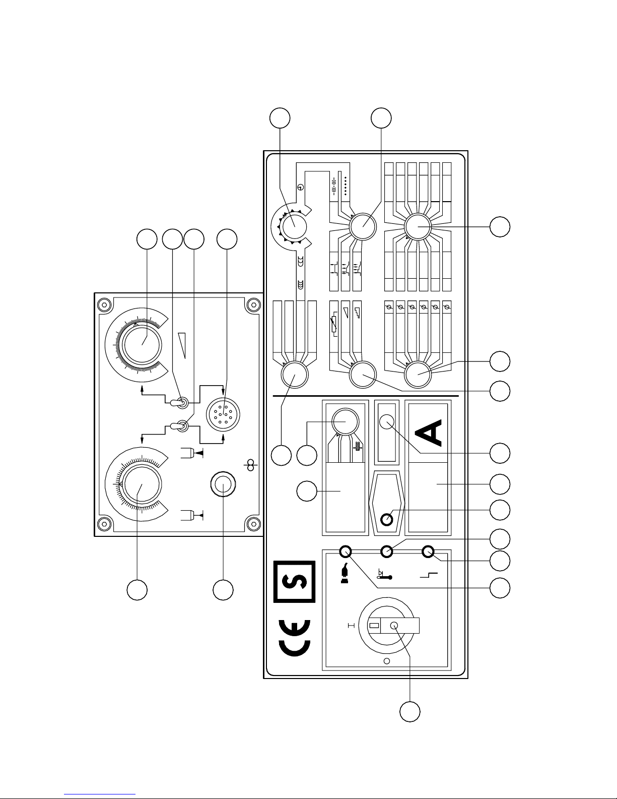
The indicated numbers below are refering to the drawing of the front
panel
1: main switch
2: selector welding process
3: selector location of energy adjustment
4: selector operation mode
5; selector material
6: selector wire diameter
7: selector read-out
8: variable resistor interpulse / welding timer
9: button gas test
10: digital read out, switchable
11: digital read out, amperage
12: LED HOLD
13: LED mains on
14: LED thermic protection
15: LED failure
17: variable resistor voltage trim / arc length (at the wire feed unit)
18: variable resistor energy (at the wire feed unit)
19: button wire currentless (at the wire feed unit)
21: trimmer down slope time (inside of the generator, on top of the front panel)
22: trimmer final current (inside of the generator, on top of the front panel)
23: trimmer start current (inside of the generator, on top of the front panel)
24: trimmer intermission time (inside of the generator, on top of the front panel)
25: switch remote control energy (at the wire feed unit, option)
26: switch remote control voltage trim (at the wire feed unit, option)
27: socket for remote control or push-pull torch (option)
9 Operation of the Unit PU 400 / 520 DW
9.1 Switching on the machine
Turn main switch ( 1) into position 1.
If the digital read-out (10) and (11) only indicate horizontallines the chosen welding program
does not exist.
For help see selection of the welding programs, otherwise the machine is ready for operation.
Selection of the welding programs
Selection of the material by means of the two selectors (5) and (6).
Put selector (5) in order to choose the material and selector (6) in order to choose the correct wire
diameter.
If the digital read-outs (10) and (11) are only indicating horizontal lines, the welding program
does not exist.
The list of welding programs is displayed at the inside of the wire feeder box.
11

9.2 Selection of the welding process
With selector (2) the welding process can be selected:
MIG-MAG, PULSE, INTERPULSE and STICK ELECTRODE WELDING. If the digital readouts (10) and (11) only show horizontallines, the chosen welding program does not exist.
1. MIG-MAG welding
With variable resistor ( 17) individual adaption of the arc voltage ( arc length)
2. PULSE welding
With variable resistor ( 17) individual adaption of the arc voltage ( arc length)
3. INTERPULSE welding
With variable resistor (17) individual adaption of the arc voltage (arc length). With
variable resistor (8) the interpulse parameters are changed, i.e. left turn is fine scaled
welding, right turn is coarse scaled welding.
Interval welding is not possible in interpulse operation.
4. STICK ELECTRODE welding
With variable resistor ( 17) arc-force is adjusted:
Left turn = no increasing of the welding current
Right turn = maximum increase of the welding current
9.3 Setting of the welding energy
With selector (3) the adjusting selector for the welding energy is chosen.
1. Variable resistor
In this position the energy is set by the variable resistor (18) at the machine. With switch (25) a
remote control box can be used.
2. TEDAC
The welding energy is adjusted by means of the slide switch on the TEDAC-torch and limited to
a maximum value by variable resistor (18).
3. Fixed welding programs (jobs)
See further functions
9.4 Setting of the operation mode
With selector (4) the operation mode is chosen.
2-stroke operation
Selector ( 4) in position “2-stroke”.
In this position the torch interruptor is used to start and to switch off the machine.
12

4-stroke operation
Selector (4) in position “4-stroke”.
Torch interruptor pressed: welding process is started
Torch interruptor released: welding in process
Torch interruptor pressed: welding, “down slope” of the welding current down
to the “final current”
Torch interrupter released: welding arc is cut off
4-stroke operation with special welding program
Selector (4) in position “special 4-stroke”
Torch interrupter pressed: the welding process is started with the “start current”
Torch interruptor released: welding with selected energy
Torch interrupter pressed: down slope” of the energy down to the “final current'”
Torch interruptor released: welding arc is cut off
4. Stitch operation
Selector ( 4) in position “stitch”.
The welding time can be adjusted by variable resistor (8) (range: 0.5- 2.5 sec.) Time of
intermission is adjusted by a trimmer inside the machine.
5. Spot welding
Selector ( 4) in position “spot welding”.
With variable resistor (8) the welding time can be adjusted (range: 0.5 -2.5 sec.)
With variable resistor (8) the start current is adjusted in relation to the selected welding
current (in % )
Insertion of the wire
With button (19) the wire is inserted without welding current.
The feeding speed increases slowly up to approximately 15m/min.
Testing shield gas
With button (9) the gas flow can be checked. Button (9) pressed: gas valve is switched on, Button
(9) released: gas valve is still switched on, Button (9) pressed: gas valve is still switched on
Button (9) released: gas valve is switched off or the gas valve is automatically switched off after
10 s
Digital read-outs
The welding unit is equipped with two digital read-outs.
These digital read-outs dispose of the pre-indication and HOLD-function of the welding
parameters, i. e. indication of the preselected welding current and welding voltage (or
wire feed speed or thickness of material).
13

After the welding process the last welding values are hold as long as LED (12) is enlighted or the
arc is enlighted again or the welding energy is changed.
Upper display (10):
With selector (7) following parameters can be displayed:
a) welding voltage in V
b) wire feed speed in m/min
c) material thickness in mm
Stick electrode welding: the actual welding voltage is always indicated.
Lower display (11 ):
The welding current is always indicated (in amps. )
9.5 Safety cut off
In case of no arc is established within about 2 s, the welding process is automatically cut off in
any selected operation mode.
9.6 Adjusting of 'start current', 'down slope' time, 'final current' and 'intermission' time
(These trimmers are located inside of the generator on top of the front panel pc-board)
1. Start current
With trimmer (23) the start current in the position “special 4-stroke”
can be adjusted
Left turn max. corresponds to -50 %,
right turn max. corresponds to + 50 % of the welding current chosen.
2. Final current
With trimmer (22) the final current in the down slope process (special 4-stroke operation)
can be adjusted.
The current is independent of the adjusted welding current -in case of the welding current
is inferior to the adjusted final current, there is no down slope.
3. Down slope time
The down slope time is adjusted by trimmer (21 )
4. Intermission time
Using interval welding the intermission time can be changed by trimmer (24) in the range
0.5s to 2.5s.
14

10 Activation of the fixed TEDAC programs (jobs)
Selecter (3) in position “fixed TEDAC programs (jobs)”
Activation of the welding programs by using the TEDAC slide switch on the TEDAC-torch.
Programs 1-4 correspond to: 1 = green
2 = yellow
3 = orange
4 = red
In this operation mode the variable resistors for the energy (18), the arc length (17) as well as
selector (2) are out of function. The welding process is selected by the fixed program.
Pre-indication of the upper digital read-out:
According to the position of selector (7) welding voltage in V,
wire feed speed in m/min or
thickness material in mm
Pre-indication of the lower digital read-out: welding current in A
The welding process is indicated by a point at the right side of the welding current display ( 11 ):
MIG-MAG no point
PULSE point at the right side
INTERPULSE side point is flashing
10.1 Generating your own TEDAC program
1) Press down button (9) and pull simultaneously the TEDAC-slide switch mounted
on the TEDAC-torch for about 5 s. Herewith you enter the program mode.
2) Press the TEDAC-slide switch on the TEDAC-torch towards the front to select the
individual program point (P1: green, P2: yellow, P3: orange, P4: red).
3) Set selector (2) on the desired welding process (MIG-MAG, PULSE, INTERPULSE).
4) Select the desired arc by the variable resistor ( 18 - energy) and the variable resistor
(17 - arc length).
5) Weld with these parameters and adjust them as requested.
6) Store this setting of these parameters by pulling the TEDAC-slide switch for about 5 s.
The storage is confirmed by the indication by the letters “STO” in the display for about 1 sec.
7) Herewith this program (job) is stored.
8) Proceed in the same way with the three remaining programs.
9) For leaving the program mode, press down button (9) and pull simultaneously the TEDAC-
slide switch mounted on the TEDAC-torch for about 5 s.
15

11 Pulse-Arc Welding Units PU 400 DW and PU 520 DW
11.1 Advantages – Point by point
¾ Compact and clearly arranged housing:
Generator, control panel, control and water cooling system are mounted in one housing.
¾ Rotating mounting of the wire feeder on the welding unit.
The swivelling axis is placed asymmetrically at the rear of the wire feeder and allows a wide
work area. The wire feeder rotates easily to the desired position without kinking the torch lead.
Due to this construction, the movements of the connection cable is reduced to a minimum.
¾ Safe transport due to the locking of the wire feeder. - Connection cables available in different
lengths: Quick and easy change due to clampable and pluggable couplings on both sides.
¾ Gas bottle holder for 10, 20 and 50 I cylinders. Lowered for an easy handling of the
cylinders. Galvanized: no corrosion due to possible frictions.
¾ Large swivel and carriage wheels for an easy handling in the workshop and in the plant. - 4
lifting eyes to transport the welding unit (option).
¾ Reduced electrical consumption in stand-by-operation. - Demand-on switching of the water
pump and ventilator.
¾ High efficiency factor due to a modern electronic.
¾ Special filters avoid radiation.
- tremendous time saving due to reduction of
working hours for cleaning
- high output of wire melting
- long endurance of torch consumables
- extended switch-on time when using machine welding.
¾ Safe, spatter reduced ignition due to a new ignition process controlled by 14
parameters:
- 2 independent ignition pulses
- precise soft start of the wire
- slag droplet on wire removed for re-ignition.
¾ 144 stored welding programs for
- different materials
- different wire diameters
- different protective gases
- Pulse-Arc, MIG/MAG and Interpulse welding.
16

¾ Multiples variations of the pulse parameters:
Manipulation of the arc characteristics and the penetration.
¾ Application of thicker wire diameters compared to MIG/MAG welding.
Savings due to purchase of thicker wire.
¾ Alloy elements are maintained due to
adaption of the pulse parameters when using high alloyed wire.
¾ Structure of the Pulse-Arc welding programs:
Flexible program structure with 35 free programmable
parameters. Perfect ignition due to 13 variable parameters
within the ignition process. 144 different pulse forms
programmable. Generating of different forms of welding
characteristic curves for the welding parameters possible.
¾ New procedure of MIG/MAG short arc welding process
Due to the new technology, already in short arc welding a very
spatter reduced weld is achieved. The range of
the non-desired mixed arc is reduced to a minimum.
¾ Comparison spatters MAG/Pulse-Arc welding:
Spatter emission in relation to the welding current
in percent. The comparison shows the outstanding
results in favour of the Pulse-Arc welding
and the traditional MAG welding using
CO? or mixed gas as protective gas.
11.2 Construction of the housing:
1) Easy to service and to open, all components clearly arranged with easy access.
2) Electronical components are dust protected placed in a separate department.
3) Easy mounting of the connection cable due to clamp-able and pluggable fittings.
4) Efficient cooling of all power components in the air tunnel.
11.3 Locking of the control panel
¾ reduction of the functions to a minimum:
Main switch, LED-displays, gas check, adjusting of the energy and arc length
(both at the wire feeder).
¾ only authorized persons can manipulate the operation modes and programs.
¾ in operation mode "Fixed Programs" the welder can activate 4 different free
programmable welding caracteristic curves at the TEDAC-torch.
17

12 Cleaning
IMPORTANT:
!!! Before opening the machine, disconnect it from mains !!!
Open the side covers. Remove dust from all parts of the machine.
Blow away the dust at the pcbs of the inverter withcompressed air –reduced pressure
(appr. 0,5 – 1 bar). We recommend to clean the unit in regular periods.
13 Maintenance and Accident Prevention
The maintenance of the welding machine consists of a regular cleaning and inspection. It depends
on the environment of the working area and the working hours.
The machine should be cleaned in regular intervals to guarantee a proper operation. The length of
the cleaning interval depends on the operation time, surrounding atmosphere etc.
ATTENTION: Before opening the welding machine, make sure
that it is disconnected from the mains supply. Wait for
components to be sufficiently cooled down !
Wait until the capacitors are discharged (appr. 3 min.)!
14 Trouble Shooting
14.1 Machine does not operate after switching on the main switch
a) Check main supply
b) Check main fuses
14.2 Machine does not react on the torch switch
a) Problem at the torch switch
b) Check internal fuses
14.3 Machine has no or too low welding current
a) Main relais is not working
b) Bad or no contact at the earth lead
c) Torch hose completely or partially broken
d) Problem with rectifier or IGBT- switches in the machine
e) Only 2 main phases are connected, check main fuses
18

14.4 Welding quality is not good
a) No or too low gas flow
b) Air is mixed into the protective gas. Open gas valve and close it again. Gas pressure
must remain in the gas hose. Check at the regulator.
c) Gas nozzle or tip holder are covered with spatters. Gas flow is not o.k.
d) Tip holder is not fixed properly. Air is mixed into the protective gas via the wire
e) Extremly oxidated workpiece.
f) Air is comming to the welding area because of wind.
14.5 Problems with wire feeding and wire contacting
a) Hole in the contact tip has wrong diameter or contact tip must be changed.
b) Wire core is extremly dirty.
c) Kinks in the wire core.
15 Aluminium Welding
1. Aluminium welding wire:
- Wire diameter 0.8 mm only with push pull torch
- Wire Al-Mg 3/5/4.5 Mn (1.0 mm), Al-Si, Al 99.5 (1.0 and 1.2 mm) torch lead max. 3 m
- For welding wire 1.6 mm we recommend a torch with a long torch head
- Do not store alu wire without the platic protection cover. Do not use alu wires with oxid.
2. Teflon liner:
- For wire 1.0 mm we recomend the teflon liner (red 2,0 x 4,0) (part-no. 022.1.0586)
- For 1.2 and 1.6 mm carbon teflon liner (yellow 2,7 x 4,7), (part-no. 022.1.0588)
- The carbon teflon liner must be installed without any break from the contact tip to the drive
roller
- Fix the clamping nut at the Euro connector only by hand
3. Wire feeder:
- Exchange the brass guidance nozzle to a pvc guidance nozzle (between the two drive rollers)
DV-25: part-no. 012.0.0373, DV-30: part-no. 012.0.0269
- Exchange the insertion nozzle at DV-30 from brass to pvc (part.-no: 012.0 0267)
- Exchange the guidance core at DV-30 to pvc (part-no: 022.1.0237)
- Install the outgoing tube in the Euro connector to support the teflon liner
Exchange the Outgoing tube (pvc) for alu/stainless steel:
DV-20: part-no. 103.001,
DV-25: part-no. 103.001,
DV-30: part-no. 102.998.
4. Wire feeding rollers:
- Exchage the two lower roller to aluminium rollers (U-groove), the rollers at the to may
remain pressure rollers without a groove
19

5. Pressure of the rollers:
- Reduce the pressure to a minimum.
- When the alu wire is stoped at the contact tip the rollers must turn without transporting the
wire.
6. Insertion of the wire:
- Insert the wire without a contact tip at the torch.
- Hold the torch cable straight, outherwise the wire could go through the line and the torch
lead.
7. Welding torch:
- We do not recommend the torch SB/SBT 154 G for aluminium welding. Use a ceramics gas
distributor (not fibre glas). Due to the high temperatures the fibre glass may emit a gas
which influences the welding process.
- The torches SB/SBT 300 W, SB/SBT 502 W and SB/SBT 600 W have an open cooling
system. Assures that the componets are tightly fitted. Only minimum parts of water will
make the aluminium welding impossible.
8. Protective gas:
- We recommend argon 4.6, mixtures argon-helium can be used for thick aluminium plates to
avoid or reduce a pre-heating.
- Gas flow for a gas nozzle 17 mm:
wire 1.0 mm: aprox. 12-14 l/min.
wire 1.2 mm: aprox. 14-16 l/min.
wire 1.6 mm: aprox. 18-22 l/min.
Avoid smaller gas nozzles.
- If the gas hose between gas valve and cylinder is long, an impulse of too much gas is ejected
during the ignition process which could cause porosity. Our wire feeder boxes have a special
reduction device installed.
- For gas hoses longer than 10 m we recommend the installation of a pressure regulator inside
the welding unit.
- We recommend a regulator with an integrated ball-flowmeter.
9. Position and distance of the torch:
- Aluminium is welded in forward position, the torch is tilt aprox. 10 - 20°.
- Distance torch to work piece aprox. 10-15 mm. If the distance is too large, the protective gas
shield is not assured.
- Avoid draught (air movement in the room).
10. Cleanliness:
- Aluminium work pieces must be without any dirtying. Clean with alcohol or special
aluminium cleaner
- Avoid the storage under high humidity.
- Remove oxid when aluminium pieces have been stroed a lon time.
11. Additional wire equipment:
- In our general catalogues in section 10 we offer complete packages for wire equipments.
12. Special 4-stroke:
- We recommend to operate in the special 4-stroke mode with a higher start current. The start
current, the down slop and the final current can be adjusted inside the machine behind the
front panel.
16 Wire feeder systems
20

Drahtvorschubgetriebe DV-25
2
1
4
3
6
5
7
8
10
9
11
12
14
13 15
16
17
19 20 21 23
3518
22 34
242526
27
282930 32
21
31
33
39
E 2715-39

16.1 Spare parts wire feeder model: DV-25
(If spare parts for the wire feeder are needed, always indicate number of the relative
positon and part number)
Pos Description _Part No._
Wire feed gear complete 002.0.2850
with motor and wire feed rollers
1 gear flange (brass part) 002.0.2875
gear flange (complete) 012.0.0287
(Euro connector preassembled)
2 lentil flat-head screw 090.0.0825
3 insulation bush 002.0.2877
4 knurled screw M 4 x 20 090.0.1002
5 bolt (roller) 002.0.2859
6 bolt 002.0.2864
7 rocking bar 002.0.2865
8 cylindrical pin 090.0.0571
9 thread pole M 8 x 90 002.0.2863
10 knurled nut 002.0.2862
11 compression spring 002.0.2690
12 pressure piece 002.0.2861
13 thread case 002.0.2860
14 rocking bar 002.0.2866
15 bullet button 002.0.2856
16 pvc liner 012.0.0377
17 permanent magnet motor 24 VDC 002.0.2630
18 hexagon screw 090.0.4335
washer 090.0.1208
spring ring 090.0.1408
22

Pos Description _Part No._
19 insulation plate 002.0.2876
20 gear insulation 012.0.0285
21 gear angle 002.0.2874
22 sheet steel protection 002.0.2870
23 outgoing nozzle (brass) 6 x 2 x 48 002.0.0367
Outgoing tube (brass) for alu/stainless steel 103.001
6 x 4 x 51
24 bolt (roller) 002.0.2873
25 for mild steel/stainless steel:
drive roller with groove V ∅ 0,6 mm 002.0.2879
drive roller with groove V ∅ 0,8 mm 002.0.2880
drive roller with groove V ∅ 1,0 mm 002.0.2881
drive roller with groove V ∅ 1,2 mm 002.0.2882
for aluminium:
drive roller ∅ 0,8 mm alu 002.0.2884
drive roller ∅ 1,0 mm alu 002.0.2885
drive roller ∅ 1,2 mm alu 002.0.2886
drive roller ∅ 1,6 mm alu 002.0.2887
26 knurled screw M 4 x 10 090.0.1001
27 fastener 002.0.2869
28 drive pinion 002.0.2871
29 guidance nozzle (brass) for steel 5 x 1,5 x 40 002.0.2867
guidance nozzle for alu/stainless steel 012.0.0373
(pvc) 5 x 1,5 x 40
30 knurled screw 002.0.2857
31 pressure roller 002.0.2878
32 screw (brass) 025.1.1610
33 incoming nozzle 002.0.2891
34 retaining ring 002.0.2858
39 edge protection rubber (0,3 m) 001.0.0820
23

Wire feeder DV-30
50
1
48
49
3
2
5-
4
8
7
10
11
57
14
15
16
17
51
52
54
57
47
12
18
20
22
24
19
21
23
66
26
25
27
58
28
29
30
31
46
.
63-
32
45
34
33
37
38
39-
42
43
44
24

16.2 Spare parts wire feeder model: DV-30
(If spare parts for the wire feeder are needed, always indicate the number of the relative
positon and part number)
Pos Description _Part No._
Wire feeder block DV-30, without motor, without rollers 012.0.0352
1 Gear box DV-30 012.0.0353
2 left rocking bar 012.0.0276
3 pressure piece 012.0.0261
4 gripping yoke 012.0.0259
5 leveling screw 012.0.0260
6 compression spring 002.0.2688
7 screw 012.0.0266
8 cylindrical pin 090.0.0587
9 compression spring 002.0.2688
10 right rocking bar 012.0.0277
11 eccentric (tentering lever) 012.0.0258
12 knurled screw 090.0.1001
13 hexagonal screw 090.0.4313
14 guide roll 012.0.0239
15 adjusting roll 012.0.0238
16 clamping sleeve 2,5 x 4,5 025.1.1524
17 introductory liner 2,5 x 4,5 002.0.2905
18 sliding block 012.0.0257
19 incoming nozzle for steel 0,8-1,6 (brass) 012.0.0332
19 a incoming nozzle for alu and stainless steel 012.0.0267
0.8-1.6 (pvc)
25

Pos Description _Part No._
20 guidance nozzle for steel 0,8-1,6 (brass) 012.0.0274
20a guidance nozzle for alu and stainless steel 0.8-1.6 (pvc) 012.0.0269
21 feather 090.0.8815
22 DU bush (inside the gear block) 019.1.0121
23 gear (drive pinion) 012.0.0279
24 insulation plate 002.0.0144
25 leveling screw 003.0.1506
26 screw pin 090.0.3303
27 screw pin 090.0.3409
28 DU bush 019.1.0550
29 cylindrical pin 090.0.0598
30 screwpin 090.0.3413
31 bolt 012.0.0268
32 gear pre-assembled 012.0.0278
33 retaining ring 090.0.1814
34 spacing ring 012.0.0235
35 cylinder-head screw 090.0.0937
36 washer 090.0.1205
37 groove ball bearings 019.1.0261
38 feather 090.0.8810
39 eye bolt 090.1.2528
40 compression spring 002.0.2690
41 hexagonal nut 090.0.6055
42 insulation bush 002.0.0200
26

Pos Description _Part No._
43 knurled nut 012.0.0265
44 for mild steel and stainless steel:
drive roller V 1,0 and 1,2 mm ∅(2 pcs. needed) 012.0.0272
pressure roller (2 pcs. needed) 012.0.0271
drive roller V 0,8 and 1,6 mm ∅ (2 pcs. needed) 012.0.0273
pressure roller (2 pcs. needed) 012.0.0271
for aluminium:
drive roller U 1,0 and 1,2 mm ∅ (2 pcs. needed) 012.0.0281
pressure roller (2 pcs. needed) 012.0.0271
drive roller U 0,8 and 1,6 mm ∅ (2 pcs. needed) 012.0.0282
pressure roller (2 pcs. needed) 012.0.0271
for cored wire:
drive roller for cored wire 1,2 and 1,6 mm ∅ (2 pcs. needed) 012.0.0291
pressure roller (2 pcs. needed) 012.0.0271
drive roller for cored wire 2,0 and 2,4 mm ∅ (4 pcs. needed) 012.0.0292
drive roller for cored wire 2,8 and 3,2 mm ∅ (4 pcs. needed) 012.0.0293
45 O ring 013.8.0010
46 sliding block 012.0.0254
47 outgoing nozzle for steel 0,8-1,6 mm ∅ (brass) 012.0.0333
outgoing nozzle for cored wire 1,6-2,4 mm ∅ (brass) 012.0.0335
outgoing nozzle for aluminium 0,8-1,6 mm ∅ (pvc) 102.998
48 lentil flat-head screw 090.1.0825
49 insulation bush 002.0.2877
50 gear insulation 012.0.0285
51 insulating plate 002.0.2876
52 gear flange complete (euro connector) 012.0.0287
53 cylinder-head screw 090.0.0931
54 insulating bush 002.0.2877
55 washer 090.0.1204
56 self-locking screw nut 090.0.6053
27

Pos Description _Part No._
57 knurled screw 090.0.1002
58 screw nut (for gas) 002.0.2896
59 hexagonal screw 090.0.4328
60 washer 090.0.1207
61 spring ring 090.0.1407
62 screw nut 090.0.5008
63 hexagonal screw 090.0.4335
64 washer 090.0.1208
65 spring ring 090.0.1408
66 motor 42 VDC (DV-30) with tacho 002.0.2512
28

17 Torches - and Spare parts
for torch model SB/SBT 502 W - PP/PPT 502 W
17.1 MIG-MAG-welding torch model SB/SBT 502 W
Technical data:
Cooling: water cooled
Mixed gas: 500 A 60 % duty cycle
CO2: 500 A 100 % duty cycle
Wire diameter:
Solid wire: 0.8 – 1.0 – 1.2 – 1.6 mm ∅
Aluminium wire: 1.0 – 1.2 – 1.6 mm ∅
Weight: approx. 1300 g/1 m H
The data are corresponding to (U = 14 + 0.05 x I)
29

MIG-MAG- welding torch model SB/SBT 502 W
30

MIG/MAG Hand Welding Torch,
Model SB/SBT 502 W, water cooled
Pos. Description Part No.
MIG/MAG hand welding torch 022.1.1587
model SB 502 W, 3 m, short version
MIG/MAG hand welding torch 022.1.1588
model SB 502 W, 4 m, short version
MIG/MAG hand welding torch 022.1.1581
model SB 502 W, 3 m, long version
MIG/MAG hand welding torch 022.1.1582
model SB 502 W, 3 m, long version
MIG/MAG hand welding torch 022.1.1601
TEDAC, SBT 502 W, 3 m, short vers.
MIG/MAG hand welding torch 022.1.1602
TEDAC, SBT 502 W, 4 m, short vers.
MIG/MAG hand welding torch 022.1.1603
TEDAC, SBT 502 W, 3 m, long vers.
MIG/MAG hand welding torch 022.1.1604
TEDAC, SBT 502 W, 4 m, long vers.
Standard wire equipment: mild steel 1.2
Spare parts and consumables:
1-6 Torch neck SB/SBT 502 W 022.1.1564
short version
1-6 Torch neck SB/SBT 502 W 022.1.1560
long version
2 Insulation sleeve for 022.1.1574
SB/SBT 502W
3 O-ring 14 x 4 VE 10 pcs 022.1.0077
4 Pressure sleeve for SB/SBT 502 W 022.1.1424
5 O-ring 12 x 4 VE 10 pcs 022.1.0076
6 water coat for SB/SBT 502 W 022.1.1572
7 Insualtion ring SB/SBT 502 W VE 10 pcs 022.1.1421
8 Tip holder SB/SBT 300/502 W VE 10 pcs 022.1.1578
9 Contact tip Cu-Cr-Zr 0.8 mm VE 10 pcs 045.1.1814
9.1 Contact tip Cu-Cr-Zr 1.0 mm VE 10 pcs 045.1.1815
9.2 Contact tip Cu-Cr-Zr 1.2 mm VE 10 pcs 045.1.1816
9.3 Contact tip Cu-Cr-Zr 1.6 mm VE 10 pcs 045.1.1817
31

Pos. Description Part No.
10 Diffusor SB/SBT 502W, ceramic VE 10 pcs 022.1.1567
10.1 Diffusor SB/SBT 502, fibreglass VE 10 pcs 022.1.1568
11 Gas nozzle 17 mm VE 10 pcs 045.1.4300
with fastening ring
11.1 Gas nozzle 14 mm VE 10 pcs 045.1.4301
with fastening ring
11.2 Spot welding gas nozzle VE 10 pcs 045.1.4304
with fastening ring
11.3 Gas nozzle 21 mm heavy duty VE 10 pcs 045.1.4305
with fastening ring
12 Contact tip AL/VA 0.8 mm VE 10 pcs 045.1.1812
12.1 Contact tip AL/VA 1.0 mm VE 10 pcs 045.1.1810
12.2 Contact tip AL/VA 1.2 mm VE 10 pcs 045.1.1811
12.3 Contact tip AL/VA 1.6 mm VE 10 pcs 045.1.1813
15 Handle MIG, complete 105.016
with trigger and cover cap
Only for SBT 502 W:
16 TEDAC pc-board ME-BE-10.0 022.1.0800
incl. slide switch and micro switch
18 Trigger for MIG/MAG torch 022.1.0796
19 Micro switch MIG/MAG torch 022.1.0797
20 Spring for switch VE 10 pcs 022.1.0131
21 Complete cable assembly, w.c. 022.1.1642
3 m, with Euro-connector,
without torch, without liner
21.1 Complete cable assembly, w. c. 022.1.1644
4 m, with Euro-connector,
without torch, without liner
22 Water-power-cable 3.0 m long 022.1.0281
22.1 Water-power-cable 4.0 m long 022.1.0282
23 Wire feeding hose cpl. 3.0 m long 022.1.1662
23.1 Wire feeding hose cpl. 4.0 m long 022.1.1664
24 Water hose flow, 3.0 m long 022.1.0290
24.1 Water hose flow, 4.0 m long 022.1.0291
25 Gas hose, 3.0 m long 022.1.0300
25.1 Gas hose, 4.0 m long 022.1.0301
26 Switch-cable, 3 m long 022.1.0148
26.1 Switch-cable, 4 m long 022.1.0149
27 Protective-hose, 3.0 m long 006.0.1055
27.1 Protective-hose, 4.0 m long 006.0.1054
28 Liner for steel (blue) 022.1.0246
0.6 - 0.8 (1.0) mm, 3 m long
28.1 Liner for steel (blue) 022.1.0247
0.6 - 0.8 (1.0) mm, 4 m long
28.2 Liner for steel (uncoated), 022.1.0248
1.0 - 1.6 mm, 3 m
32

Pos. Description Part No.
28.3 Liner for steel (uncoated), 022.1.0249
1,0 - 1.6 mm, 4 m
30 Euro-connection, at torch side 025.1.0150
31 Brass neck for Euro-connection 025.1.0200
32 Kinking-protection, intake 025.1.0100
33 Euro adapter nut 025.1.0300
34 Liner nut VE 10 pcs 025.1.1301
35 Water-return-hose 022.1.0295
36 Coupling nipple no. 3305 025.1.0400
37 Teflon liner for alu and stainl.st. 022.1.0586
0.8 - 1.2 mm, 3 m (red, 2.0 x 4.0)
with brass outgoing liner
37.1 Teflon liner for alu and stainl.st. 022.1.0588
(1.2) - 1.6 mm, 3 m (yellow, 2.7 x 4.7)
with brass outgoing liner
38.1 Collet for teflon liner 2.0 x 4.0 min 10 pcs 107.554
38.2 Collet for teflon liner 2.7 x 4.7 min 10 pcs 102.997
39.1 Outgoing nozzle pvc, DV-25 103.001
for aluminium and stainless steel
39.2 Outgoing nozzle pvc, DV-30 102.998
for aluminium and stainless steel, 0.8 - 1.6 mm
1.2 - 1.6 mm, 3 m (2.7 x 4.7 mm)
41 Kinking protection 022.1.1580
42 Spring for kinking protection 022.1.1579
43 Connection nipple for VE 10 pcs 045.1.0201
water-current-cable, torch side
44 Nipple for wire feeding hose at VE 10 pcs 045.1.0312
torch side
Protection hose 26 x 1.5 VE 120 m 027.2.0100
Water hose blue 5 x 1.5 VE 100 m 027.2.0130
Water hose red 5 x 1.5 VE 100 m 027.2.0125
PVC hose with textile 9 x 12 mm VE 100 m 006.0.0103
Only for SB 502 W:
45 Cover cap for TEDAC handle 022.1.0604
* max. length of torch lead for alu: 3 m
33

17.2 Push-Pull-welding torch model PP/PPT 502 W
Technical data:
Cooling: water cooled
Mixed gas: 500 A 60 % duty cycle
CO
: 500 A 100 % duty cycle
2
Wire diameter:
Solid wire: 0.8 / 1.0 / 1.2 / 1.6 mm ∅
Aluminium wire: 1.0 / 1.2 / 1.6 mm ∅
Weight: approx. 1850 g/1 m H
The data are corresponding to (U = 14 + 0.05 x I)
34

Push-Pull-welding torch model PP/PPT 502 W
35

Push Pull Hand Welding Torch,
Model PP/PPT 502 W, water cooled
Pos. Description Part No.
Push pull hand welding torch 021.1.0296
model PP 502 W, straight, 8 m
Push pull hand welding torch 021.1.0297
model PP 502 W, bent, 8 m
Push pull hand welding torch 021.1.0298
TEDAC, PPT 502 W, straight, 8 m
Push pull hand welding torch 021.1.0299
TEDAC, PPT 502 W, bent, 8 m
Standard wire equipment: mild steel 1.0
Spare parts and consumables:
1 Motor-block PP torch 021.1.0151
3 Wire feeding roller st. 0.8 mm (PP) 021.1.0251
3.1 Wire feeding roller st. 1.0 mm (PP) 021.1.0252
3.2 Wire feeding roller st. 1.2 mm (PP) 021.1.0253
3.3 Wire feeding roller st. 1.6 mm (PP) 021.1.0254
3.4 Wire feeding roller alu 0.8 mm (PP) 021.1.0255
3.5 Wire feeding roller alu 1.0 mm (PP) 021.1.0256
3.6 Wire feeding roller alu 1.2 mm (PP) 021.1.0257
4 Wire feeding motor, PP-torch 021.1.0272
5 Pressure-yoke cpl. PPL/PPW 021.1.0160
6 Pressure roller PP 021.1.0170
7 Fastening-yoke cpl. 021.1.0181
8 Spring DFO, 7x4, 3x9, 3x4x1.12 021.1.0182
for fastening yoke 021.1.0181
9 Intake-nozzle PP 307 021.1.0190
motor-block/intake
10 Kinking protection 021.1.0279
13 Guiding nut 021.1.0205
14 Torch handle, PP-torch, rear 021.1.0235
15 Torch handle, PP-torch, front 021.1.0236
16 Cover 021.1.0237
17 Spring lock 021.1.0185
18 Toorch interruptor 021.1.0335
19 Cover cap for TEDAC handle 022.1.0604
20 Variable resistor PP-torch 001.0.0506
21 Turn-knob 003.0.1508
22 Torch lead cpl. 8 m, PP/PPT 502 021.1.0285
without torch, with Euro-connection
36

Pos. Description Part No.
23 Wire feeding hose 8 m 021.1.0283
24 Gas hose 8 m 021.1.0260
25 Control cable cpl., 7-pole 021.1.0331
26 Protective hose 25 x 1.5 006.0.1053
27 Euro-connection, at torch side 025.1.0150
28 Kinking-protection, intake 025.1.0100
29 Brass neck for Euro-connection 025.1.0200
30 Euro adapter nut 025.1.0300
31 Wire core 8 m 021.1.0329
2.0 x 4.0 mm
31.1 Wire core 021.1.0325
BZ 0.6 - 1.6 mm, 8 m, cpl.
32 Liner nut 025.1.1301
33 Socket 10-pole (-) 021.1.0384
(for push pull torch)
34 Cable terminal cpl. with strain 021.1.0387
relief for energy switch, 410
35 Collet for teflon liner 2.0 x 4.0 107.554
36 Teflon liner 2.0 x 4.0 021.1.0326
Alu/stainl. steel 0.8 - 1.6 mm, 8 m
37.1 Outgoing nozzle pvc, DV-25 103.001
for aluminium and stainless steel
37.2 Outgoing nozzle pvc, DV-30 102.998
for aluminium and stainless steel
38 Spring for kinking protection 022.1.1579
39 Brass liner 0.2 m, (2.0 x 4.0) 107.810
40 Torch neck PP/PPT 502, straight 021.1.0097
41 Torch neck PP/PPT 502 W, 45° 021.1.0096
42 Insulation sleeve for SB/SBT 502W 022.1.1574
43 O-ring 14 x 4 VE 10 St 022.1.0077
44 O-ring 12 x 4 VE 10 St 022.1.0076
45 Pressure sleeve for SB/SBT 502 W 022.1.1424
46 water coat for SB/SBT 502 W 022.1.1572
47 Insualtion ring SB/SBT 502 W VE 10 St 022.1.1421
48 Tip holder SB/SBT 300/502 W VE 10 St 022.1.1578
49 Contact tip Cu-Cr-Zr 0.8 mm VE 10 St 045.1.1814
49.1 Contact tip Cu-Cr-Zr 1.0 mm VE 10 St 045.1.1815
49.2 Contact tip Cu-Cr-Zr 1.2 mm VE 10 St 045.1.1816
50 Diffusor SB/SBT 502W, ceramic VE 10 St 022.1.1567
50.1 Diffusor SB/SBT 502 VE 10 St 022.1.1568
51 Gas nozzle 17 mm VE 10 St 045.1.4300
with fastening ring
51.1 Gas nozzle 21 mm heavy duty VE 10 St 045.1.4305
with fastening ring
37

Pos. Description Part No.
52 Spot welding gas nozzle VE 10 St 045.1.4304
with fastening ring
53 Gas nozzle 14 mm VE 10 St 045.1.4301
with fastening ring
55 TEDAC pc-board ME-BE-10.0 022.1.0800
incl. slide switch and micro switch
56 Insertion element 021.1.0337
57 Water hose 8 m long 021.1.0271
58 Water-return-hose 022.1.0295
59 Coupling nipple no. 3305 025.1.0400
60 Water-power-cable 8 m long 021.1.0321
38

18 Stored programs PU 400
PU400
EPROM
1.73
Prg-Nr. material Gas diam. 0,8 diam. 1,0 diam. 1,2 diam. 1,6 1 Spezial 2 Spezial
1 SG 2+3 82 Ar/18 Co2
2 SG 2+3 100 Co2
3 Cr-Ni 97,5 Ar/ 2,5 Co2
4 Al-Mg 3-5 99,996 Ar
5 Al-Si 5 99,996 Ar
6 Al-Mg 4,5 Mn 99,996 Ar
7 Cu-Si 3 99,996 Ar
8
9 Fluxofil 31 82 Ar/18 Co2
10
11
12
Programs MIG/MAG
* * * *
* * * *
* * * *
* * *
* * *
* *
* *
* *
Programs Pulse
date: 20.03.02
Prg-Nr. Werkstoff Gas diam. 0,8 diam. 1,0 diam. 1,2 diam. 1,6 1 Spezial 2 Spezial
1 SG 2+3 82 Ar/18 Co2
2 SG 2+3 82 Ar/18 Co2
3 Cr-Ni 97,5 Ar/ 2,5 Co2
4 Al-Mg 3-5 99,996 Ar
5 Al-Si 5 99,996 Ar
6 Al-Mg 4,5 Mn 99,996 Ar
7 Cu-Si 3 99,996 Ar
8
9 Fluxofil 31 82 Ar/18 CO2
10 Cu-Al 8 99,996 Ar
11
12
* * * *
*
* * * *
* * * *
* * * *
* * 1,2 He30
* *
* *
* * * *
39

19 Spare parts and wiring diagram
Spare part list PU 400 DW
19.1
electr. description part no.
A0 pc-board ME-NF400/2.5 102.279
A1 pc-board ME-l-PG-1.0 003.0.0001
A2 pc-board ME-l-PI-1.0 003.0.0002
A3 pc-board ME-I-SD-1.1B 003.0.0003
A4 pc-board ME-I-RC-1.1 003.0.0004
A5 LEM-converter 010.0.1615
A6 pc-board ME-2QR-24/42-2.1C 003.0.0046
A7 pc-board ME-PPMR-2.1 003.0.0493
A8 pc-board ME-MTC-1.2 003.1.0042
E-prom MTC-MP-I.X 003.0.0381
E-prom PU4001.X 003.0.0382
A9 pc-board ME-MTC/M-2.0 100.198
A10 pc-board ME-MF-1.3 003.1.0000
A11 Platine ME-EMV-3.1 102.281
A12 pc-board ME-PPMR/AN2.0 003.0.0485
C1 capacitor 0,1 uF 1000V 001.0.0415
F1 fuse 4 A slow - control transformer prim. 400V 003.0.1251
F2 fuse 4 A slow - control transformer prim. 400V 003.0.1251
F3 fuse 10 A slow - control transformer sec. 37 V - 42V 003.0.1199
F4 fuse 1 A slow -control transformer sec. 42 V 003.0.1212
F6 water pressure switch 0,5 bar 004.0.0204
F7 thermic switch - 80 °C opening – rectifier 001.0.0406
F8 thermic current switch 1,4 A - water pump 003.0.0320
K1 relais 48V/AC 010.0.1961
relaissocket 010.0.1962
M1 wire feed motor 42 V DC (at DV-30) GR63X55 109.702
M2 fan 230 V AC - water cooling torch 001.0.1323
M3 fan 230 V AC - water cooling torch 001.0.1323
M4 fan 230 V AC - at the inverter 001.0.1323
M5 fan 230 V AC - at the inverter 001.0.1323
M6 water pump 230 V AC 004.0.0530
M7 wire feed motor 24 V DC (at DV25) 002.0.2630
Q1 main switch HLT 40 001.0.0014
40

electr. description part no.
-R1
-R2
-R3
-R4
-R5
-R7
-R8
potentiometer 10 kΩ
potentiometer 10 kΩ
resistor 330 Ω 50W
resistor 330 Ω 50W
NTC resistor 47 kΩ
resistor 0,02 Ω 50W
resistor 330 Ω 50W
001.0.0545
001.0.0545
030.0.4583
030.0.4583
010.0.1933
030.0.4580
030.0.4583
-S1 selector 2-pole (option socket machine welding) 003.0.0900
-S2 selector 2-pole-energy 003.0.0900
(option PP- and socket for remote control)
-S3 selector 2-pole voltage trim 003.0.0900
(option PP- and socket for remote control)
-S4 button wire feed 010.0.0325
-T1 Transformer and choke of inverter 020.1.1661
-T2 Control transformer EI 120/73,7 950VA 003.0.0242
-T3 Saturation transformer (green) 020.1.1124
-V1 Rectifier prim. 001.0.0285
-X1 Dinse-bush 70/95mm² 500A 001.0.1102
-X1 Socket DIX SE 50/70 012.0.1508
-X2 Dinse-bush 70/95mm² 500A 001.0.1102
-X3 Dinse-bush 70/95mm² 500A 001.0.1102
-X6 Euroconector 012.0.0287
-X7 Socket 6-pole (option machine welding) 015.0.0102
-X8 Support for bush 24-pol. 015.0.0501
-X8 Support for pins 24-pol. 015.0.0500
-X9 Conector 24-pole 015.0.0502
-X10 Socket 10-pole 021.1.0386
(option PP- and remote control)
Connector 10 pole (accessories) 021.1.0383
strain relief (accessories) 021.1.0388
-Y1 Gas valve 42V/AC 002.0.1602
-Z1 Protection device 003.0.0334
-Z2 Protection device 100.894
19.2 wiring diagram PU 400
41

1 2 3 4 5 6 7 8
-V4
-V3
-A2
-
+
+
T-Prim.
T-Prim.
16
1
ME-I-PI-1.0
X3
-A4
ME-I-RC-1.1
X1
87654321
-V5
2 4
31
-V7
2 4
31
-V10
2 4
31
-V8
2 4
31
-V9
2 4
31
-V1
-
+
-V2
1 2 3 4
1
2
-R3
-R4
1
2
+SQ
-X2
+SQ
-X3
+SQ
-A5
2 3 41
1 2 3 4
-T3
+SQ
-Q1
L1 L2 L3
T1 T2 T3
L1 L2 L3
PE
-X11
1
-R8
-V6
2 4
31
+SQ
-Z2
-X5
PE
+SQ
-X1
+SQ
-Z1
+INV-A3-X4/2.6
+INV-A3-X12/2.4
+INV-A3-X10:1/2.3
+INV-A3-X10:2/2.3
+INV-A3-X10:3/2.3
+INV-A3-X10:4/2.3
+INV-A3-X7:3/2.5
+INV-A3-X7:1/2.5
-A1
L1L2L3
+
F1F2F3
0,2A
0,2A
0,2A
21 3 4 1 10
1
2
U>Umax
U<Umin
rt
rt
Überst./
over current
U<
Prim.DC
gn
ME-I-PG-1.1
-
-
-
-
-
X1 X2
X4
rt
+
+
U>
1
2
X3
-
+
-T1
+SQ-T2:0V/2.1
+SQ-T2:400V/2.1
-R7
+SQ
-A0
L1
L2
L1´
L2´
PE
ME-NF400/2.5
+SQ
-A11
L1 L2 L3
PE
L1´L2´L3´
ME-EMV-3.1
+SQ
-X4
PE
sw
sw
sw
rt
bl
bl
bl
rt
br
br
br
br
br
br
rt
rt
bl
bl
bl
rt
bl
sw
sw
sw
ws
gr
gn
-
+
Werkstück/
work piece
Elektrode/
stick electrode
Brenner/
torch
+
3PH-400V/50Hz/PE
Blatt
7
Bl.
1
Projektbez.
Auftragsnr.
Zeichnungsnr.
PU400DW
Änderung
Datum
gez.
gepr.
Name
Datum
Name
Konrad
01.04.99
Siegner
14.07.99
Konrad
15.11.99
Schweißstromkreis
Vervielfältigung oder Weitergabe nur mit unserer schriftlichen Genehmigung gestattet
c
dab
Plotdatum:
08.10.03
Merkle
Schweißanlagen-Technik GmbH
Industriestraße 3
D - 89359 Kötz
Telefon 08221 -915 - 0
Telefax 08221 - 32596
=
+
INV

1 2 3 4 5 6 7 8
-T2
sw1/sw2
w2-9V
w2-0V
400V
230V
0/230V
0/230V
0V
w3-0V
w3-37V
w3-42V
w4-18V
w4-0V
w5-9V
w6-9V
w7-18V
w7-0V
w8-18V
w8-0V
w9-18V
w12-42VPEw12-0V
w11-9V
w11-0V
w10-9V
w10-0V
w9-0V
w5-0V
w6-0V
w1
5A1A1A2A1A1A1A
1A
1A
1A
-F1
4A
-F2
4A
-F3
10A
-F4
1A
1
2
3
4
5
786
1
2
3
4
5
6
7
8
9
+INV-A1-X2/1.3
+INV-A2-X3/1.6
+SQ-A8-X2/3.4
14 3
1
2
3
4
3
4
789
101112
1
5
6
234
-M4
PE
M
-M5
PE
M
-M6
PE
bl
schw
br
M
-F8
+SQ-A0:L1´/1.2
+SQ-A0:L2´/1.2
+INV-A3-X9:1/2.6
+INV-A3-X9:2/2.6
+INV
-M2
PE
M
+INV
-M3
PE
M
-X4
PE
+INV
-X5
PE
+SQ-T2:230V/2.1
+SQ-T2:0/230V/2.1
+SQ-X8:7/3.1
+SQ-X8:8/3.1
+SQ-T2:w12-0V/2.1
+SQ-T2:w12-42V/2.1
+OP2-X7:1/3.8
+OP2-X7:2/3.8
+SQ-A5-X1:4/1.7
+SQ-A5-X1:3/1.7
+SQ-A5-X1:2/1.7
+SQ-A5-X1:1/1.7
+INV
-F7
Gleichrichter/
rectifier
+INV
-R5
NTC-IGBT
U
+INV
-R6
NTC-Trafo
U
+SQ-A6-X1:4/3.4
+SQ-A6-X1:3/3.4
+SQ-A8-X1:1/3.2
+SQ-A8-X1:2/3.2
+SQ-A8-X1:3/3.2
+SQ-A8-X1:4/3.2
-F6
P
+INV-A3-X8:12
2.6
+INV-A3-X8:11
2.6
-X4
PE
-X4
PE
+SQ-X8:21/3.1
-A3
Übertemp./over temp.
Untersp./under voltage
Störung/failure
WD.fehlt/no water pressure
T>50C°
POL
Start
I>0
rtrtrtrtrtrtrt
rt
Übersp./over voltage
rt
Idyn
Istat
PWM-ON
+15VP
gn gn ge
rt
UeILIUeT
LT
+5V
+15V
-15V
rtrtge
ge
gn gn gn
RES
I>0
HF
Gas
rt
rtgngn
rt
ge
ext
Res
intern
intern
I>0
Reg.
Spr.
PU500
X1
1 34
1
10
X4
123456789
101112
123
12345
6
X14
132
4
5
6
1
2
3
4
1
2
3
4
5
6
7
8
X6
X2
X10
X9
X8
Res.
I>0
TIG
MAG
Gas
1 16
Lüfter/fan
Idyn.
Istat.
X12
ME-I-SD-1.1
1234
-
U ist
1
2
3
4
5
6X57
8
9
10
X7
+
Lüfter/
fan
Wasserp./
pump
Wasserp./pump
+INV-R8/1.6
+INV-X11:1/1.7
sw
sw
sw
bl
br
rt
21
1
2
sw
sw
bl bl
rtswblswrt
bl1sw
22
18
10
9
gn 2
gr1ws
sw
4
3
22
19
6
5
8
7
4
3
sw
9
10bl11
12sw22sw18
Lüfter/
fan
Pumpe/
pump
Lüfter/
fan
Blatt
7
Bl.
2
Projektbez.
Auftragsnr.
Zeichnungsnr.
PU400DW
Änderung
Datum
gez.
gepr.
Name
Datum
Name
Konrad
07.04.99
Siegner
14.07.99
Steuerstromkreis
Vervielfältigung oder Weitergabe nur mit unserer schriftlichen Genehmigung gestattet
c
dab
Plotdatum:
08.10.03
Merkle
Schweißanlagen-Technik GmbH
Industriestraße 3
D - 89359 Kötz
Telefon 08221 -915 - 0
Telefax 08221 - 32596
=
+
SQ

1 2 3 4 5 6 7 8
1
2
5
6
3
4
1
2
3
4
5
6
+SQ-T2:w3-42V/2.1
+SQ-T2:w3-0V/2.1
-X8
1
2
3
4
5
6
7
8
9
10
11
12
13
14
15
17
18
19
20
21
22
23
24
16
+SQ-T2:w4-18V/2.1
+SQ-T2:w4-0V/2.1
+SQ-T2:w5-9V/2.1
+SQ-T2:w5-0V/2.1
1
2
3
4
5
6
7
+INV-A3-X1/2.5
+INV-A3-X8:3/2.6
+INV-A3-X8:4/2.6
+INV-A3-X7:4/2.4
+SQ-A10-X1/4.5
1
2
3
4
-C1
+OP1
-A7
rt
Freigabe/
enable
X4
ME-PPMR-2.1
X1
1
2
3
4
5
6
7
8
X2
1
2
3
4
5
6
1 10
X3
JP1
JP2
>3m
1A-träge/
slow
-A8
1 16 1 2 3 4 5 6 1 10 1 34 1
2
3
4
1
2
3
4
5
6
7
8
1
2
3
4
120 1 19
1
X3
X14
X8
X9
X1
X6 X7 X5 X2
X15
ME-MTC-1.2
B
A
GND
X4
Energy
Korrektur/trim
Taster Draht/button wire feed
+5V
26
-A9
X12
X13
X11 X10
Um
UO
IO
Im
X13
JP2
PU250
RES.
PU500
PU400
11
1 1
ME-MTC/M-2.00
+OP1
-A12
ME-PPMR/AN 2.0
rt
+
rt
gn
0
-
110
X1
+OP2
-S1
1
2
3
Hand/Automatik
+INV-A3-X8:7/2.6
+INV-A3-X8:8/2.6
+SQ-X8:9/3.1
+SQ-X8:10/3.1
+SQ-T2:w12-42V/2.1
+OP2
-K1
A1
A2
+SQ-T2:w12-0V/2.1
+OP2
-K1
5
9
+OP2
-K1
6
10
+INV-A3-X5:8/2.3
+INV-F7/2.2
+INV-A3-X6:8/2.3
+INV-A3-X6:7/2.3
+OP2
-X7
12345
6
-A6
110
ge
X2
345
6
1
2
3
4
5
6
1
2
ME-2QR-24/42-2.1C
+
-
-
+
X1
42V/AC
TACHO
ANKER/
core
-15V
+15V
U Soll
+5V
GND
X3
Freigabe/
enable
Bremsen/
brake
Freigabe/
enable
gn
max
min
-A12
123456789101112
on
T/A
T/A
T/A
A/TC1C2C3C4R1R2R3R4
ME-2QR/DIP-1.0
10
9
11 11
14
17
12
16
14
13
24
23
12
11
21
10 22
9
11
14
17
12 23
16 19
10
9
9 2
10 1
11
12
26
4 25
23
3 24
22
22
18
19
20
26
25
.8
.8
5
1
2
3
468
7
9
10
11
12
.7 .7
ext. Absenken
auf Wunsch
Option: Push-Pull-Anschluß/
remote control
C1 nur bei DV 30/
C1 only at DV30
Option: Automatenanschluß/
machine welding connection
Blatt
7
Bl.
3
Projektbez.
Auftragsnr.
Zeichnungsnr.
PU400DW
Änderung
Datum
gez.
gepr.
Name
Datum
Name
Konrad
07.04.99
Siegner
14.07.99
Steuerstromkreis
Vervielfältigung oder Weitergabe nur mit unserer schriftlichen Genehmigung gestattet
c
dab
Plotdatum:
08.10.03
Merkle
Schweißanlagen-Technik GmbH
Industriestraße 3
D - 89359 Kötz
Telefon 08221 -915 - 0
Telefax 08221 - 32596
=
+
SQ

1 2 3 4 5 6 7 8
+SQ-A8-X3/3.3
+INV
-A10
1 20
2
1
2
1
P4 P3 P2 P1
JP1
Absenkzeit/
down slope
Endstrom/
final current
Startstrom/
start current
Rückbrand/
burn back
Netz/
mains
Übertemp./
over temp.
Hold
Gas Test
A
V
mm
m/min
X1
2
1
S2
S3 S5
ME-MF-1.3
X2
0.6
0.8
1.0
1.Spec.
2.Spec.
3.Spec.
Poti
TEDAC
Festprg.
MIG/MAG
Elektrode
S1
S4
2
1
2
1
Schweißzeit
El-Hochstart
P5
Intervall
Punkten
ALSi
AL99S1S2
AL-MG
CrNi
SG 2+3
SG 2+3
Schalter/switch
S1 -S6
1 = extern
2 = intern
2-Takt
4-Takt
S-4Takt
Tig
123456789
101112131415161718
Störung/
failure
Blatt
7
Bl.
4
Projektbez.
Auftragsnr.
Zeichnungsnr.
PU400DW
Änderung
Datum
gez.
gepr.
Name
Datum
Name
Konrad
07.04.99
Siegner
14.07.99
Frontplatine
Vervielfältigung oder Weitergabe nur mit unserer schriftlichen Genehmigung gestattet
c
dab
Plotdatum:
08.10.03
Merkle
Schweißanlagen-Technik GmbH
Industriestraße 3
D - 89359 Kötz
Telefon 08221 -915 - 0
Telefax 08221 - 32596
=
+
SQ

1 2 3 4 5 6 7 8
1
2
3
4
5
6
7
8
9
10
11
12
13
14
15
16
17
18
19
20
21
22
23
+VB
-X8
24
1
2
3
4
5
6
7
8
9
10
11
12
13
14
15
16
17
18
19
20
21
22
23
-X9
24
2
3
4
5
6
7
8
9
10
11
12
13
14
15
16
17
18
19
20
21
22
23
1
-M1
+
-
+
G
=
M
=
+VB
-X9
24
-Y1
+OP1
-X10
B
A
K
J
H
G
F
E
D
C
M
=
E
A
S
E
A
S
-S4
-R1
E
A
S
-R2
E
A
S
-S2
123
-S3
123
B
A
-X6
+
+VB
-X1
-X12
1
+OP3
-M7
-
+
M
=
24
23
21
18
17
16
15
14
13
12
11
10
9
8
7
Energy
BT.
BT.
PP-Motor
Energy
B
A
Option:
PP-und Fernregleranschluß/
remote control
1
2
3
4
+DV
-X9
Motor für Option:
DV-25
Zentralanschluß
(Ansicht Maschinenfront)
EURO connector
(front view)
VB-Kabel/
connection cable
DV-Gerät DV-30
wire feeder
Taster Draht/
botton wire feed
Korrektur/
trim
Korrektur/
trim
Blatt
7
Bl.
5
Projektbez.
Auftragsnr.
Zeichnungsnr.
PU400DW
Änderung
Datum
gez.
gepr.
Name
Datum
Name
Konrad
07.04.99
Siegner
14.07.99
DV-Kasten
Vervielfältigung oder Weitergabe nur mit unserer schriftlichen Genehmigung gestattet
c
dab
Plotdatum:
08.10.03
Merkle
Schweißanlagen-Technik GmbH
Industriestraße 3
D - 89359 Kötz
Telefon 08221 -915 - 0
Telefax 08221 - 32596
=
+
DV

1 2 3 4 5 6 7 8
111
0
1 0
001 1 1 1
000
000
000
111
0 1
000
234
Reglerb.C(nF)
567
8
47
100
230
470
100
0
001
1
001
0
001
0
001
1
Reglerb.R(kOhm)
9
101112
499
221
100
49,9
0
0
0
0
0
0
00
0
0
0
1
1 1
1
1 1
1
0
0
Wenn beim Drehzahleinstellen auf dem ME-2QR24/42-2.1C
die gelbe Brems-LED flackert Max. Trimmer auf Mitte stellen
erst dann Min und Max Drehzahl wiederholt einstellen.
Anker
Tacho
DV-25 DV-25 DV-30 DV-30 DV-30
ohne Tacho
mit Tacho
S1
Reglerbeschaltung
Regelung
Typ
GR 63 X55
GNM 4175-
G 10.9-T13
GP 76.40
SR6TG
Reglerabgleich ME-2QR24/42-2.1C
Blatt
7
Bl.
7
Projektbez.
Auftragsnr.
Zeichnungsnr.
PU400DW
Änderung
Datum
gez.
gepr.
Name
Datum
Name
Konrad
09.07.03
Reglerabgleich
Vervielfältigung oder Weitergabe nur mit unserer schriftlichen Genehmigung gestattet
c
dab
Plotdatum:
08.10.03
Merkle
Schweißanlagen-Technik GmbH
Industriestraße 3
D - 89359 Kötz
Telefon 08221 -915 - 0
Telefax 08221 - 32596
=
+

Layout pcb MTC 1.2/ PU 400
JP1
JP2
nur bei PU250
ME-MTC/M-2.X
M8 M7 M6 M5 M4 M3 M2 M1 M 0
MTC-2
PU400-1.X
Datum
Datum
MTC-MP-2.X
PU400:Anordnung der Eproms auf Platine ME-MTC-1.2
48

19.3 Spare Part List PU 520 DW
electr. description part no.
-A0 Pcb ME-EMV-1.1 003.0.0070
-A1 Pcb ME-I-SD / 1.1B 003.0.0003
-A2 Pcb ME-I-SD/K-1.2 003.0.0020
-A3 Pcb ME-MTC-1.2 003.1.0042
-A4 Pcb ME-MTC/M 2.0 100.198
E-Prom MTC-MP-1.X 003.0.0383
E-Prom PU 500-1.X 003.0.0384
-A5 Pcb ME-MTC/MF-1.3 003.1.0001
-A6 Pcb ME-2QR-24/42-2.1C 003.0.0046
-A7 Pcb ME-PPMR-2.1 003.0.0493
(Option PP-control)
-A8 Pcb ME-PPMR/AN-2.0 003.0.0485
(Option PP-control)
-A9 LEM-current transformer 010.0.1615
-C1 Capacitor 0,1uF 1000 V 001.0.0415
-C2 Capacitor 6 uF, 420V/AC-Lüfter 001.0.0425
-F1 Fuse 4 A, slow 003.0.1251
-F2 Fuse 4 A, slow 003.0.1251
-F3 Fuse 10 A slow 003.0.1199
-F4 Fuse 1 A 003.0.1212
-F5 Thermic switch 112 °C (open) 001.0.0408
-F6 Thermic switch 80°C (open) 001.0.0406
-F7 Thermic switch 80°C (open) 001.0.0406
-F8 Sensor over current 1,4 A 003.0.0320
-F9 Pressure switch-membran 0,5 bar 004.0.0204
-K1 Relais 48VAC (option machine welding) 010.0.1961
Relais support (option machine welding) 010.0.1962
-L1 Choke PU 500 001.0.1624
-M1 Motor-straight 200 rpm w. tacho (DV 30) GR63X55 109.702
-M2 Fan 230V 001.0.1301
-M3 Water pump 230VAC 004.0.0530
-Q1 Main switch HLT 40 001.0.0014
-R1
-R2
-R3
Poti 10 kΩ-energy
Poti 10 kΩ-voltage trim
Resistor 180 Ω 100 W
001.0.0545
001.0.0545
020.1.1099
49

electr. description part no.
R4 NTC - 100 kΩ - transformer
R5 NTC - 47 kΩ - transistor cascade 010.0.1933
S1 switch 2-pole (option machine welding) 003.0.0900
S2 switch 2-pole remote control energy (option) 003.0.0900
S3 switch 2-pol. remote control arc length (option) 003.0.0900
S4 button - wire feed 010.0.0325
T1 main transformer PU 520 001.0.1615
T2 control transformer MT 400-500/2 003.0.0242
prim.: 400V/230V/42V/9V
sec. : 37-42V/18V/9V/9V
18V/18V/18V/9V/9V
V1 rectifier 001.0.0227
V2 transistor cascade 001.0.0268
X1 Dinse-bush 70/95mm² 500A 001.0.1102
X1 Socket DIX SE 70/95 012.0.1508
X2 Dinse-bush 70/95mm² 500A 001.0.1102
X3 Dinse-bush 70/95mm² 500A 001.0.1102
X5 plug 5-pol. 017.0.0617
X6 Euroconnector 012.0.0287
X7 connector 6 -pol. pin connection for automated welding (option) 015.0.0102
X8 connector 24-pol. socket wire feeder connection 015.0.0501
X8 connector 24-pol. pin wire feeder connection 015.0.0502
X9 connector 24 -pol. pin connection inside the wire feeder 015.0.0502
X9 connector 24 -pol. socket connection inside the wire feeder 015.0.0501
X10 connector 10-pol. remote control and
push-pull connection (option) 021.1.0386
plug 10-pol. 021.1.0383
strain relief 021.1.0388
Y1 gas valve 42VAC 002.0.1602
Z1 Protection device 100.894
Z2 Protection device 003.0.0334
19.4 wiring diagram PU 520
50

1 2 3 4 5 6 7 8
-Q1
L1 L2 L3
T1 T2 T3
L1 L2 L3
PE
-T1
PE
400V
440V
380V
440V
400V
380V0V440V
400V
380V
~
~
~
-V1
E+
E-
EMITTER
+SQ-A2-X3:2/2.4
+SQ-A2-X3:4/2.4
-V2
K+
K-
A+
A-
G
S
Kaskade/
cascade
-A0
ME-EMV-1.3ME-EMV-1.3
L1L2L3
PE
-X4
PE
-A9
2 3 41
1 2 3 4
-X3
-X1
-X2
-Z1
-Z2
-L1
+SQ-A1-X10:1/2.3
+SQ-A1-X10:2/2.3
+SQ-A1-X10:3/2.3
+SQ-A1-X10:4/2.3
+SQ-A1-X7:3/2.5
+SQ-A1-X7:1/2.5
+SQ-T2:0V/2.1
-A10
L2
L3
L2´
L3´
PE
ME-NF400/2.5
+SQ-T2:400V/2.1
-X4
PE
sw
bn bn
bl
gr
sw
sw
ws
gr
gn
rt
bl
3PH-400V/50Hz/PE
+
+
-
Brenner/
torch
Elektrode/
stick electrode
Werkstück/
work piece
Blatt
7
Bl.
1
Projektbez.
Auftragsnr.
Zeichnungsnr.
PU520DW
Änderung
EMV-Filter
ME-NF400/2.5
Datum
gez.
gepr.
Name
Datum
Name
Konrad
01.04.99
Siegner
14.07.99
Konrad
Konrad
30.05.00
13.12.01
Schweißstromkreis
Vervielfältigung oder Weitergabe nur mit unserer schriftlichen Genehmigung gestattet
c
dab
Plotdatum:
08.10.03
Merkle
Schweißanlagen-Technik GmbH
Industriestraße 3
D - 89359 Kötz
Telefon 08221 -915 - 0
Telefax 08221 - 32596
=
+
SQ

1 2 3 4 5 6 7 8
-T2
sw1/sw2
w2-9V
w2-0V
400V
230V
0/230V
0/230V
0V
w3-0V
w3-37V
w3-42V
w4-18V
w4-0V
w5-9V
w6-9V
w7-18V
w7-0V
w8-18V
w8-0V
w9-18V
w12-42VPEw12-0V
w11-9V
w11-0V
w10-9V
w10-0V
w9-0V
w5-0V
w6-0V
w1
5A1A1A2A1A1A1A
1A
1A
1A
-F1
4A
-F2
4A
-F3
10A
-F4
1A
1
2
3
4
5
6
1
2
3
4
5
6
7
8
14 3
+SQ-X8:21/3.1
+SQ-V2:A+/1.4
+SQ-V2:A-/1.4
1
2
3
4
3
4
789
101112
2
4
+SQ-A10:L2´/1.3
+SQ-A10:L3´/1.3
+SQ-A1-X9:1/2.6
+SQ-A1-X9:2/2.6
+SQ-X8:7/3.1
+SQ-X8:8/3.1
+SQ-T2:w12-0V/2.1
+SQ-T2:w12-42V/2.1
+OP2-X7:1/3.8
+OP2-X7:2/3.8
+SQ-A9-X1:4/1.7
+SQ-A9-X1:3/1.7
+SQ-A9-X1:2/1.7
+SQ-A9-X1:1/1.7
-R5
NTC-Kaskade
U
-R4
NTC-Trafo
U
+SQ-A6-X1:3/3.4
+SQ-A6-X1:4/3.4
+SQ-A3-X1:1/3.2
+SQ-A3-X1:2/3.2
+SQ-A3-X1:3/3.2
+SQ-A3-X1:4/3.2
-F9
P
+SQ-A1-X8:12
2.6
+SQ-A1-X8:11
2.6
-X4
PE
-X4
PE
2 41 6
635
1
3
+SQ-A3-X2/3.4
+SQ-V2:S/1.4
+SQ-V2:G/1.4
1 2
-M2
PE
bl
schw
br
M
-F8
1
-X4
PE
+SQ-T2:230V/2.1
+SQ-T2:0/230V/2.1
-C2
-M3
PE
bl
schw
br
M
-X5
55
22
44
11
33
-R3
10
-F7
Kaskade/
cascade
-F6
Gleichrichter/
rectifier
-F5
Trafo
-A1
Übertemp./over temp.
Untersp./under voltage
Störung/failure
WD.fehlt/no water pressure
T>50C°
POL
Start
I>0
rtrtrtrtrtrtrt
rt
Übersp./over voltage
rt
Idyn
Istat
PWM-ON
+15VP
gn gn ge
rt
UeILIUeT
LT
+5V
+15V
-15V
rtrtge
ge
gn gn gn
RES
I>0
HF
Gas
rt
rtgngn
rt
ge
ext
Res
intern
intern
I>0
Reg.
Spr.
PU500
X1
1 34
5
7
X4
123456789
101112
123
12345
6
X14
132
4
5
6
1
2
3
4
1
2
3
4
5
6
7
8
X6
X2
X10
X9
X8
HF
I>0
TIG
MAG
Gas
1 16
Lüfter/fan
Idyn.
Istat.
X12
ME-I-SD-1.1
1234
-
U ist
1
2
3
4
5
6X57
8
9
10
X7
+
Lüfter/
fan
Wasserp./
pump
Wasserp./pump
-A2
1 2 3 4 6 1 25
X3
X3A
X1
ME-I-SD/K-1.2
18
bl
rt
21
1
bl
2
sw
sw
7
br
7
7
sw
7
bl1sw
3
7 7
3
22
18
10
9
9
10
11 2
12 1
4
3
22
6
5
8
7
4
3
bn 9
10bl11
12
30
rt
gr
29
sw
13
15
Pumpe/
pump
Lüfter/
fan
10 pol.
Blatt
7
Bl.
2
Projektbez.
Auftragsnr.
Zeichnungsnr.
PU520DW
Änderung
Datum
gez.
gepr.
Name
Datum
Name
Konrad
07.04.99
Siegner
14.07.99
Steuerstromkreis
Vervielfältigung oder Weitergabe nur mit unserer schriftlichen Genehmigung gestattet
c
dab
Plotdatum:
08.10.03
Merkle
Schweißanlagen-Technik GmbH
Industriestraße 3
D - 89359 Kötz
Telefon 08221 -915 - 0
Telefax 08221 - 32596
=
+
SQ

1 2 3 4 5 6 7 8
1
2
5
6
3
4
1
2
3
4
5
6
+SQ-T2:w3-42V/2.1
+SQ-T2:w3-0V/2.1
-X8
1
2
3
4
5
6
7
8
9
10
11
12
13
14
15
17
18
19
20
21
22
23
24
16
+SQ-T2:w4-18V/2.1
+SQ-T2:w4-0V/2.1
+SQ-T2:w5-9V/2.1
+SQ-T2:w5-0V/2.1
1
2
3
4
5
6
7
+SQ-A1-X7:4/2.4
1
2
3
4
-C1
+OP1
-A7
rt
Freigabe/
enable
X4
ME-PPMR-2.1
X1
1
2
3
4
5
6
7
8
X2
1
2
3
4
5
6
1 10
X3
JP1
JP2
>3m
1A-träge/
slow
+SQ-A1-X1/2.5
+SQ-A1-X8:3/2.6
+SQ-A1-X8:4/2.6
+SQ-A5-X1/4.5
-A3
1 16 1 2 3 4 5 6 1 10 1 34 1
2
3
4
1
2
3
4
5
6
7
8
1
2
3
4
120 1 19
1
X3
X14
X8
X9
X1
X6 X7 X5 X2
X15
ME-MTC-1.2
B
A
GND
X4
Energy
Korrektur/trim
Taster Draht/button wire feed
+5V
26
-A4
X12
X13
X11 X10
Um
UO
IO
Im
X13
JP2
PU250
RES.
PU500
PU400
11
1 1
ME-MTC/M-2.00
+OP1
-A8
ME-PPMR/AN 2.0
rt
+
rt
gn
0
-
110
X1
+OP2
-S1
1
2
3
Hand/Automatik
+SQ-A1-X8:7/2.6
+SQ-A1-X8:8/2.6
+SQ-X8:9/3.1
+SQ-X8:10/3.1
+SQ-T2:w12-42V/2.1
+OP2
-K1
A1
A2
+SQ-T2:w12-0V/2.1
+OP2
-K1
5
9
+OP2
-K1
6
10
+SQ-A1-X8:9/2.6
+SQ-F9/2.7
+SQ-A2-X3:1/2.4
+SQ-A2-X3:6/2.5
+OP2
-X7
12345
6
-A6
110
ge
X2
345
6
1
2
3
4
5
6
1
2
ME-2QR-24/42-2.1C
+
-
-
+
X1
42V/AC
TACHO
ANKER/
core
-15V
+15V
U Soll
+5V
GND
X3
Freigabe/
enable
Bremsen/
brake
Freigabe/
enable
gn
max
min
-A11
123456789101112
on
T/A
T/A
T/A
A/TC1C2C3C4R1R2R3R4
ME-2QR/DIP-1.0
10
9
11
14
17
12
16
24
23
21
22
23
18
10
9
9 2
10 1
11
12
26
4 25
23
3 24
19 29
19 20 30
29
20 30
26
25
26
25
.8
.8
5
1
2
3
468
7
9
10
11
12
.7 .7
Option: Push-Pull-Anschluß/
connection
Option: Automatenanschluß/
machine welding connection
Blatt
7
Bl.
3
Projektbez.
Auftragsnr.
Zeichnungsnr.
PU520DW
Änderung
Datum
gez.
gepr.
Name
Datum
Name
Konrad
07.04.99
Siegner
14.07.99
Steuerstromkreis
Vervielfältigung oder Weitergabe nur mit unserer schriftlichen Genehmigung gestattet
c
dab
Plotdatum:
08.10.03
Merkle
Schweißanlagen-Technik GmbH
Industriestraße 3
D - 89359 Kötz
Telefon 08221 -915 - 0
Telefax 08221 - 32596
=
+
SQ

1 2 3 4 5 6 7 8
-A5
1 20
2
1
2
1
P4 P3 P2 P1
JP1
Absenkzeit/
down slope
Endstrom/
final current
Startstrom/
start current
Rückbrand/
burn back
Netz/
mains
Übertemp./
over temp.
Hold
Gas Test
A
V
mm
m/min
X1
2
1
S2
S3 S5
ME-MF-1.3
X2
0.6
0.8
1.0
1.Spec.
2.Spec.
3.Spec.
Poti
TEDAC
Festprg.
MIG/MAG
Elektrode
S1
S4
2
1
2
1
Schweißzeit
El-Hochstart
P5
Intervall
Punkten
ALSi
AL99S1S2
AL-MG
CrNi
SG 2+3
SG 2+3
Schalter/switch
S1 -S6
1 = extern
2 = intern
2-Takt
4-Takt
S-4Takt
Tig
123456789
101112131415161718
Störung/
failure
+SQ-A3-X3/3.3
Blatt
7
Bl.
4
Projektbez.
Auftragsnr.
Zeichnungsnr.
PU520DW
Änderung
Datum
gez.
gepr.
Name
Datum
Name
Konrad
07.04.99
Siegner
14.07.99
Frontplatine
Vervielfältigung oder Weitergabe nur mit unserer schriftlichen Genehmigung gestattet
c
dab
Plotdatum:
08.10.03
Merkle
Schweißanlagen-Technik GmbH
Industriestraße 3
D - 89359 Kötz
Telefon 08221 -915 - 0
Telefax 08221 - 32596
=
+
SQ

1 2 3 4 5 6 7 8
1
2
3
4
5
6
7
8
9
10
11
12
13
14
15
16
17
18
19
20
21
22
23
+VB
-X8
24
1
2
3
4
5
6
7
8
9
10
11
12
13
14
15
16
17
18
19
20
21
22
23
-X9
24
2
3
4
5
6
7
8
9
10
11
12
13
14
15
16
17
18
19
20
21
22
23
1
-M1
+
-
+
G
=
M
=
+VB
-X9
24
-Y1
+OP1
-X10
B
A
K
J
H
G
F
E
D
C
M
=
E
A
S
E
A
S
-S4
-R1
E
A
S
-R2
E
A
S
+OP1
-S2
123
+OP1
-S3
123
B
A
-X6
+
+VB
-X1
-X11
1
24
23
21
18
17
16
15
14
13
12
11
10
9
8
7
Energy
Korrektur/trim
BT.
BT.
PP-Motor
Energy
B
A
DV-Gerät DV-30/wire feeder
VB-Kabel/connection cable
Option:
PP-und Fernregleranschluß
PP-and remote control
Zentralanschluß
EURO connector
(Ansicht Maschinenfront)
(front view)
Taster Draht/
button wire feed
Korrektur/
trim
Blatt
7
Bl.
5
Projektbez.
Auftragsnr.
Zeichnungsnr.
PU520DW
Änderung
Datum
gez.
gepr.
Name
Datum
Name
Konrad
07.04.99
Siegner
14.07.99
DV-Kasten
Vervielfältigung oder Weitergabe nur mit unserer schriftlichen Genehmigung gestattet
c
dab
Plotdatum:
08.10.03
Merkle
Schweißanlagen-Technik GmbH
Industriestraße 3
D - 89359 Kötz
Telefon 08221 -915 - 0
Telefax 08221 - 32596
=
+
DV

1 2 3 4 5 6 7 8
111
0
1 0
001 1 1 1
000
000
000
111
0 1
000
234
Reglerb.C(nF)
567
8
47
100
230
470
100
0
001
1
001
0
001
0
001
1
Reglerb.R(kOhm)
9
101112
499
221
100
49,9
0
0
0
0
0
0
00
0
0
0
1
1 1
1
1 1
1
0
0
Wenn beim Drehzahleinstellen auf dem ME-2QR24/42-2.1C
die gelbe Brems-LED flackert Max. Trimmer auf Mitte stellen
erst dann Min und Max Drehzahl wiederholt einstellen.
Anker
Tacho
DV-25 DV-25 DV-30 DV-30 DV-30
ohne Tacho
mit Tacho
S1
Reglerbeschaltung
Regelung
Typ
GR 63 X55
GNM 4175-
G 10.9-T13
GP 76.40
SR6TG
Reglerabgleich ME-2QR24/42-2.1C
Blatt
7
Bl.
9
Projektbez.
Auftragsnr.
Zeichnungsnr.
PU520DW
Änderung
Datum
gez.
gepr.
Name
Datum
Name
Konrad
09.07.03
Reglerabgleich
Vervielfältigung oder Weitergabe nur mit unserer schriftlichen Genehmigung gestattet
c
dab
Plotdatum:
08.10.03
Merkle
Schweißanlagen-Technik GmbH
Industriestraße 3
D - 89359 Kötz
Telefon 08221 -915 - 0
Telefax 08221 - 32596
=
+

20 Stored programs PU 520
PU520
EPROM
1.73
Prg-
Nr. material. gas diam. 0,8 diam. 1,0 diam. 1,2 diam. 1,6 1 Spezial 2 Spezial
1 SG 2+3 82 Ar/18 Co2
2 SG 2+3 100 Co2
3 Cr-Ni 97,5 Ar/ 2,5 Co2
4 Al-Mg 3-5 99,996 Ar
5 Al-Si 5 99,996 Ar
6 Al-Mg 4,5 Mn 99,996 Ar
7 SG 2+3 HLS HLS-Gas
8
9 Fluxofil 31 82 Ar/18 Co2
10
11
12
Programs MIG/MAG
* * * *
* * * *
* * * *
* * *
* * *
* *
*
* *
date: 26.04.00
Prg-
Nr. material gas diam. 0,8 diam. 1,0 diam. 1,2 diam. 1,6 1 Spezial 2 Spezial
1 SG 2+3 82 Ar/18 Co2
2 SG 2+3 82 Ar/18 Co2
3 Cr-Ni 97,5 Ar/ 2,5 Co2
4 Al-Mg 3-5 99,996 Ar
5 Al-Si 5 99,996 Ar
6 Al-Mg 4,5 Mn 99,996 Ar
7
8
9 Fluxofil 31 82 Ar/18 CO2
10 Cu-Al 8 99,996 Ar
11
12
Programs Pulse
* * * *
*
* * * *
* * * *
* * * *
* * *
* *
* * * *
57

Layout pcb MTC 1.2/ PU 500/520
JP1
JP2
nur bei PU250
ME-MTC/M-2.X
M8 M7 M6 M5 M4 M3 M2 M1 M0
MTC-2
PU520-1.X
Datum
Datum
MTC-MP-2.X
PU520:Anordnung der Eproms auf Platine ME-MTC-1.2
58

21 EU-Conformity Attestation PU 400 DW
EU – Conformity Attestation
Description of the unit: Synergic Pulse Welding Unit
Model: PU 400 DW
The above mentionned unit complies with the following European Regulations:
EU-Low Voltage Regulation 73/23/EWG
EU-Electromagnetic Compatibility 89/336/EWG
In case of any modifications, incorrect repairs not exclusively authorized by Merkle, this
attestation looses its valdity.
Applied norms EN 60974 - 1 / IEC 974 - 1 / VDE 0544 part 1
EN 60204 - 1 / IEC 204 - 1 / VDE 0113 part 1
EN 50199
Kötz, December 20th, 1995
Wilhelm Merkle, Generalmanager
59
Merkle Schweißanlagen-Technik GmbH

22 EU-Conformity Attestation PU 520 DW
EU – Conformity Attestation
Description of the unit: Synergic Pulse Welding Unit
Model: PU 520 DW
The above mentionned unit complies with the following European Regulations:
EU-Low Voltage Regulation 73/23/EWG
EU-Electromagnetic Compatibility 89/336/EWG
In case of any modifications, incorrect repairs not exclusively authorized by Merkle, this
attestation looses its valdity.
Applied norms EN 60974 - 1 / IEC 974 - 1 / VDE 0544 part 1
EN 60204 - 1 / IEC 204 - 1 / VDE 0113 part 1
EN 50199
Kötz, January 21th, 1999
Wilhelm Merkle, Generalmanager
60
Merkle Schweißanlagen-Technik GmbH

Notes:
61

M E R K L E
Schweissanlagen-Technik GmbH
4. Edition 2003 Oktober 28th. 2003
Technical changes reserved
MERKLE
Schweissanlagen-Technik GmbH
Industriestrasse 3
D-89359 Koetz,
Germany
Tel.: ++49-8221-915-0
Fax: ++49-8221-915-40
www.merkle.de
62
 Loading...