

Service-Instructions PU 250 K
23.04.2001
1) Maschine säubern und auf äußere Schäden achten (Lackierung, Frontplatte).
2) Sichtkontrolle:
- Erstprüfung: Messungen nach EN 60204 / VDE 0113/ VDE 0701
- Gasschläuche dürfen nicht geknickt sein und nicht mit Schweißleitungen
verbunden sein;
- Kabel, Leitungen, Stecker und Schraubkontakte auf saubere Verlegung und sichere
Befestigung prüfen
- Platinenabstandshalter auf festen Sitz kontrollieren;
Check if the pcb MTC-1.2 is screwed with metal supports M3 and on the top
fixed with springs! (side pcb).
- Plug off all connectors on the pcb
- Maschine säubern, Steckkontakte auf Platinen wg. Lack prüfen
- Maschinennummer und Baujahr-Aufkleber auf Platinen, Inverter, Gleichrichter anbringen
PAL MTC 2 on pcb ME-MTC-1.2
E-Prom: MTC 1.82 / 29.06.1999 // PU 25A 1.73 / 06.03.2001
Check capacitors mounted against radiation:
0,1 µF/1000V parallel 5nF-250V between Plus-bush and housing
0,1 µF/1000V parallel 5nF-250V between Minus-Bush and housing
0,1 µF/1000V parallel 5nF-250V between wire feeding gear and housing
Grundlastwiderstand kontrollieren:
2,2 KΩ / 9W zwischen Plus-Buchse und Minus-Buchse
Check the jumpers:
on pcb ME-I2-RE-1.1:
JP1 1-2 placed;
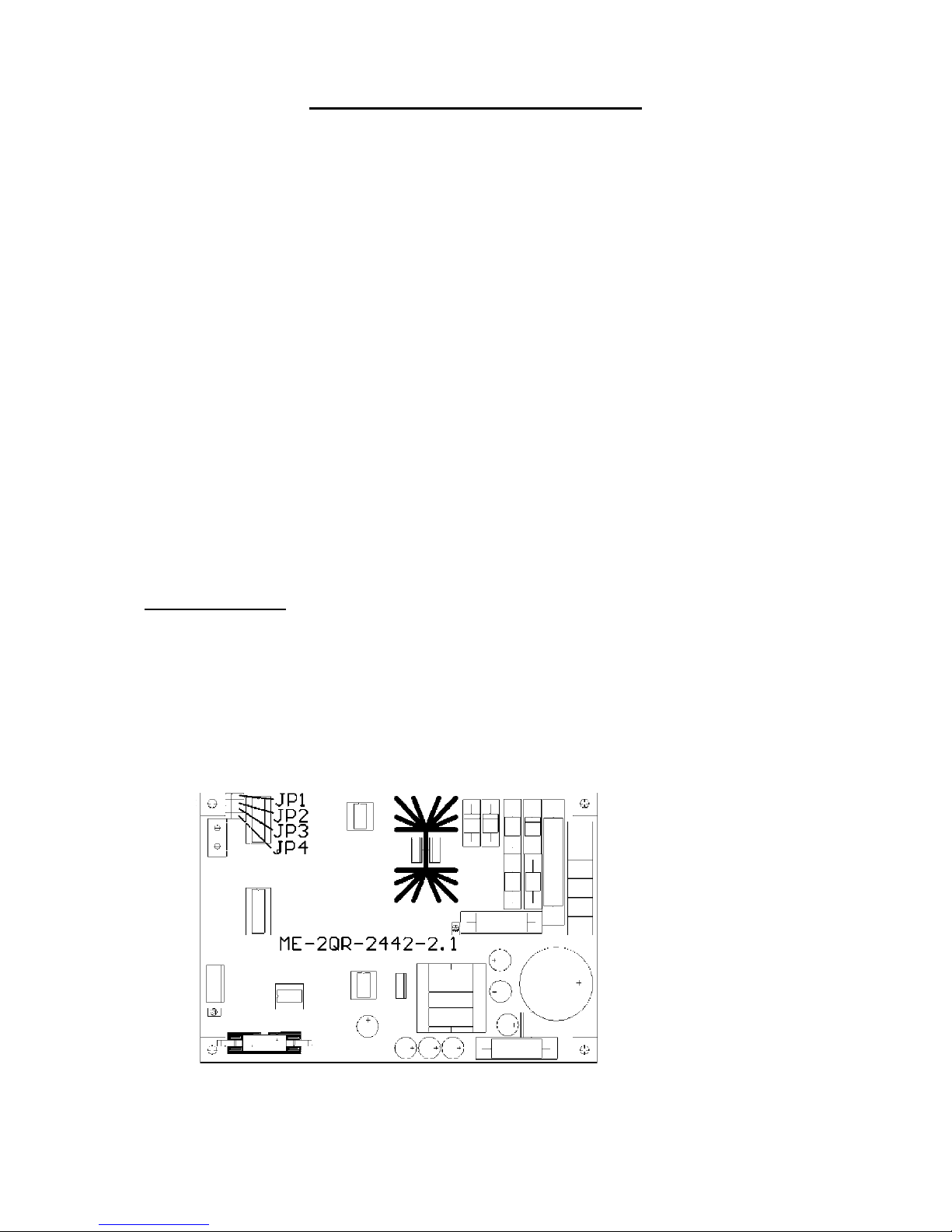
on pcb ME-2QR-24/42-2.1: DV 25
JP1 placed middle-inside
JP2 same
JP3 same
JP4 same
m
max
min
Bremse
Freigabe
Drehzahl
On pcb ME-MTC/M-2.0:
JP1 placed at PU 250
JP2 placed (TIG-Lift-Arc)
1

On pcb ME-MTC/MF -1.3:
S1, S2, S3, S4, S6 all bridges brazed on intern
2) Isolationsmessung
Kurzschlußbrücken zwischen 2 Schienen am Sekundärgleichrichter und Widerstand
10Ω/10W unten (linker Anschluß) auf Platine ME-I2-SG-1.1
Isolationsmessgerät: Prüfspannung 1000 V
Ö L1,L2,L3 (Anschlüsse am Inverter abziehen) gegen Schutzleiter
Ö Schweißtrafo primär gegen sekundär
Ö Schweißtrafo primär gegen Schutzleiter, Prüfspannung 500 V
Ö Plus - und Minus - Buchse gegen PE-Anschluß, Prüfspannung 500 V
Nach Prüfung: Kondensatoren entladen
ÖBrücke zwischen Schweißtrafo-sekundär und Gehäuse
3) Measurements of voltage:
Connect power supply cable
Main switch ON ,
Measurings with the multimeter:
Inverter pcb ME-I2-PL-1.0 L1, L2, L3 3 x 400V AC/PE
Control transformator: clamp: F1 (4At) - F2: (4At) 400 V AC
F2 (4At) - F3: (1At): 230 V AC
F4 (10At) - 37/0 37 - 39 V AC
F5 (1At) - 42/0 42 - 45 V AC
Pcb ME-I2-PL/T-1.1:
A2 - X3/1-2 9 V AC (NTC-prim.)
A2 - X7/1-2 9 V AC (over rectifier thermic sensor)
Pcb ME-I2-SD-1.3:
A3 - X8/1-2 18 V AC / 0,2A
A3 - X8/3-4 18 V AC / 0,5A
Pcb ME-2QR-24/42-2.1:
A6 - X1/3-4 37 V AC
Pcb ME-PPMR-2.1:
A7 - X2/5-6 37 V AC
Pcb ME-MTC-1.2:
A8 - X1/1-2 9 V AC
A8 - X1/3-4 18 V AC
Pcb ME-I2-PL/T-1.1: measure NTC-resistors between
X3/3, X3/4 75...125 kOhm
X8/1, X8/2 30... 75 kOhm
Main switch OFF
Plug off the primary cables of the main transformer to the pcb ME-I2-PL-1.1
(2x2 flat connectors)
Connect test device with primary winding, primary voltage value must
be more than 2.00V (app. 2.10V AC)
2
This test must be shorter than 0.5 min.! (Resistors are getting hot)

See wiring diagram measuring switching.
IGBT (Gate-Source) –measuring of the resistor:
¾
Pcb ME-I2-PL/T-1.1 between X5/1-2; X5/5-6; X6/1-2;and X6/5-6 = app. 98Ω
Ö
Plug in all connectors to the pcb:
measure resistor: electronic – M0 against PE infinite
Ω
electronic – M0 against plus-and minus bush app. 1,2 M
Ω
Connect TEDAC-torch
Selector on position frontpanel-setting:
Operation - MIG-MAG
Var. Res. Time - 0
Setting - Front
2 T / 4 T - 4-stroke
Diameter - 0.8 mm ∅
Material - SG 2+3
Main switch ON
3.1 Adjusting of the digital read out (Volts)
¾
Umin:
Pcb MTC/M 2.0 – M0 against Um with „Trimmer U0“ adjust on -25...30 mV
¾
Umax:
measure the no load voltage:
Multimeter at plus- and minus- bush
Switch to mode „ELECTRODE“ .
Measure appr. 70 V DC; the indicated voltage at the read-out can be adjusted with
„Trimmer UM“ on the measured value appr. 70V DC ,
Switch to „PULSE-ARC“, no voltage to be measured;
!!!!! Check the right polarity !!!!!
Measure the voltage at the inverter pcb ME-I2-PL-1.0 between (+) and (-) appr. 560 V DC
3.2 The following LED´s are enlighted on the pcbs:
Pcb ME-I2-SD-1.3
LED green (on X10) primary +15VP =primary OK
At the front panel: LED „mains“
LED „Error“ if one phase is missing, blinking with the option watercooling unit is
connected, if water pressure is missing
Check LED „Overtemperature“, (Disconnect connector at the temperature switch)
evtl. LED „Hold“
Digital read-out
3.3 TEDAC torch: - Poti energy on min LED - green ; Display current app. 35 A ,
Display voltage 18V
- Poti energy on max LED - red; Display current app. 250 A ,
Display voltage 33V
Main switch OFF
3

4) Adjusting of pcb RPM control: pcb ME-2QR-24/42-1.2
Check position of the jumper for (DV 25) on pcb ME-2QR-24/42-1.2!
4.1) RPM adjusting without supplementary device:
main switch ON
Positions of the selectors: PULSE-ARC, Energy setting at the unit,
0,8 mm
∅
, 4-stroke, SG2+3, Display on „Volts“
Program mode
Ö
Press botton Gas and pull back TEDAC-sliding switch app. 5sec.
Poti energy on position app. 20%
Turn poti voltage until the upper display shows „dF“
Move TEDAC-slide switch until the other display shows „0“
Turn poti voltage until the upper displays shows „dr“
Adjust wtith TEDAC-slide switch until the other display shows 2.5 = 2,5 m/min.
Short circuit between contact tip and work piece
Press torch trigger
Anchor back voltage on pcb ME-2QR-24/42-2.1:
X1 - 5-6 adjust to app. 4,4V-DC with trimmer “min”
Release torch trigger
Take away the contact tip from the work piece
Display switches back to „dr 2.5“ after 10 sec
Adjust with poti energy on app. 70%
Ö
Display shows app. 25.0 = 25 m/min.
Short circuit between contact tip and work piece
Press torch trigger
Anchor back voltage at pcb ME-2QR-24/42-2.1:
X1 - 5-6 adjust at app. 37,3V-DC with trimmer “max”
Release torch trigger
Take away the torch from the work piece
Check again min. adjusting
Main switch OFF Ö - RPM setting program will be deleted
Main switch ON Ö - Re -Loading of the program from the EPROM starts
4.2). RPM setting with a supplementary device:
Disconnect the flat cable from the pcb ME-2QR-24/42-2.1 plug in the connector of the
supplementary device at connector X3.
„Usoll 1V“ free ON
⇔
adjust anchor back voltage at X1 – 5-6 on app. 4,4V-DC with
trimmer “min” free OFF
„Usoll 10V“ free ON ⇔ adjust Anchor back voltage at X1 – 5-6 on app. 37,0V-DC
with trimmer “max” . Free OFF
Check again adjusting „Usoll 1V“
All trimmers to be sealed with vernis.
4

4.2 Current adjusting at the LEM-current transformer
Ö
Adjusting of zero at the current transformer LEM (mode=PULSE-ARC):
Multimeter at M0(-) and M4(+) at pcb ME-I2-SD-1.3 (Multimeter-mV-range) with P1 at the
LEM. Value: -20mV to -25 mV .
Program mode
Press green botton gas check and pull back the TEDAC-slide switch for app. 5sec.
Setting of the poti „Energy“ to app. 20%
Setting of the poti "Arc voltage" and TEDAC to the following values:
IG 195
IP 205 A
tp 1,8 s
F 285 Hz
SAn 1
SAb 2
Ur xxx
dF 0
dr xxx
rb xxx
I xxx
U xxx
d xxx
Adjusting of max. value at the LEM / check polarity:
Mode= PULSE-ARC
Setting of the current 200 amps at the display with the poti
Pcb MTC/M-2.0 ( M0 [ - ] and IS [ + ] Isoll = 2V-DC)
Make short circuit with a shunt between bush electrode and bush work piece
Measure current with the shunt (300A - 300mV)
⇒
Press torch trigger = ON
Adjust 200A +/- 2A at the LEM with trimmer P2 (=Shunt voltage 200mV)
Check with a Multimeter at M0 (-) and Iist (+) at pcb ME-MTC/M-2.0 = 2,0V-DC
⇒
Press torch trigger = OFF
Main switch OFF
All trimmers to be sealed with vernis;
5

5) Welding
5.1 Mode: MIG-MAG / Pulse-Arc
Bremswirkung des Spulenhalters kontrollieren, ggf. fetten;
DV-Getriebe ausrüsten;
Flucht Einlaufdüse - DV-Rolle - Kappilarrohr einstellen;
Anpressdruck der Druckrolle einstellen (Antriebsrolle muß trotz eines gewissen Gegendrucks
von Hand Draht sauber fördern);
Zur Einstellung des Anpressdrucks Taster "Draht stromlos" verwenden;
Gas (Mischgas) anschließen ÖGasdichtigkeit prüfen
Schweißleitung mit Steckerteil an Anlagenrückseite in Pluspol-Buchse stecken
und durch Rechtsdrehen sichern;
Werkstückleitung mit Minuspol-Buchse verbinden und durch Rechtsdrehen sichern;
MIG-MAG-Schweißbrenner am Zentralanschluß anschließen;
Mode „PULSE-ARC“, Selectors for material and wire dia. at SG2+3, 0,8 mm
∅
;
Function at postion „Special 4-stroke“;
Adjusting at position „Welding unit“;
Pre selection at the display of 200amps;
Press the torch trigger in no load voltage- Istart-Indication at app. 240A +/- 10A , evtl.
adjusting with trimmer „Start current“ ;
Release Torch trigger and press again – Indication has to go down to app ca. 70 A , evtl.
adjusting with trimmer „End current“;
Adjust down slope time to app. 1 sec., evtl. with trimmer „down slope time“ ;
If the safety cut off switching is working, repeat the same procedure;
Mesure voltage at the Current sensor (limitation of the primary current), : pcb ME-I2-SD 1.3
In MAG mode: adjust welding current to 135 amps and mesure app. 100 mV between
M0 - M8.
Welding over the complete welding range
5.2 Mode TIG:
Ö
LED “TIG” enlighted
Mode “TIG”, Selector material on any position
exept “SPEZIAL” and ”TIG-PULSE”
Function at postion “2-stroke or 4-stroke”;
Adjusting at position “Adjusting welding unit”;
Setting of the TIG-parameters
Set selector material to the corresponding parameter ;
This parameter can be adjusted by pressing down the botton “wire feeding” and at the same
time turning the poti“ Arc voltage”. The upper display (Selector at -V- m/min
or –mm -).
Eine Änderung des Parameters erfolgt erst durch Drehen am Potentiometer “Korrektur”.
Wird der Taster “Draht-stromlos” nicht mehr gedrückt, kann der vorgewählte Parameter im
EE-PROM abgelegt und dauerhaft gespeichert werden.
6

Leuchtet die LED“Hold“, kann kein Parameter eingestellt werden. Sie erlischt durch Drehen
am Potentiometer Energie.
Einstellung bei Auslieferung
Ö Absenkzeit 2 sek. Ö Gasnachströmen 10 sek.
Ö I1 TIME 1 1 sek. Ö I2 TIME 2 1,5 sek.
Ö I2 % z.B. 100 A = 50 % bei Hauptstrom (I1) 200 A
(oberes Display)
Der TIG-Lichtbogen wird durch Kontakt-Zündung gezündet.
Dabei ist empfehlenswert, zuerst die Wolframelektrode am Werkstück aufzusetzen und
danach den Brennertaster zu betätigen. Der Lichtbogen wird durch seitliches Abkippen
des Schweißbrenners gezündet.(LIFT-ARC-Zündung).
Der Schweißstrom wird am Energiepotentiometer eingestellt.
Measure welding current (with shunt) at the digital read out and adjust with trimmer „Im“
(max. current) and trimm poti „I0“ (min. current) at pcb ME-MTC/M-2.0 in mode „TIG“ .
Welding the complete range
TIG-PULSE
Das Schweißen erfolgt mit den eingestellten Zeiten “TIME 1, TIME 2 und
Strom I2% (abhängig von Strom I1 )
Strom I2 %
Bei Betriebsart „Sonder 4-Takt“ kann durch kurzes Antippen (< 0,5 sek.) mit dem
Brennertaster zwischen Hauptstrom und Strom I2 % umgeschaltet werden.
6.3 Betriebsart:Elektrode
Werkstückleitung mit Pluspol-Buchse verbinden und durch Rechtsdrehen sichern;
Schweißleitung mit Elektrodenhalter in Minus-Buchse stecken und durch Rechtsdrehen
sichern;
Hotstart: einstellbar mit dem „Zeitpotentiometer“
Linksanschlag kein Hotstart
Rechtsanschlag Hotstartstrom ist 200 % von eingestelltem Schweißstrom
Arc-Force (Stromnachregelung): einstellbar mit Potentiometer „Korrektur“
Linksanschlag oder „Korrektur 0“ kein Arc-Force
Rechtsanschlag max. Strom (begrenzt auf 330 A)
Schweißstrom ca 130 A Ö Elektrode in Schweißbad drücken Ö Korrekturpotentiometer zu
Rechtsanschlag drehen ÖSchweißstrom muß sich erhöhen
Faustformel für Schweißstrom: pro mm-Elektroden-∅ ca. 40A Schweißstrom
All trimmers to be sealed with vernis;
Note failure, their cause and their reparation !
7
 Loading...