

MERKLE M 302 K, M 352 K, M 302 D, M 352 D, M 352 KW Operation Manuals
...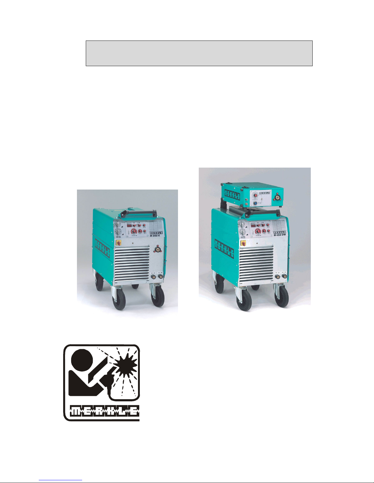
Operation Manual
MIG-MAG Welding Unit
M 302 K/D
M 352 K/D/KW/DW
M 452 KW/DW
M 552 DW
MERKLE
Schweissanlagen-Technik GmbH
Industriestrasse 3
D-89359 Koetz,
Tel.: ++49-8221-915-0
Fax: ++49-8221-915-40
www.merkle.de
Germany

.

Content page
1st
Security indications before introduction 4
2nd Accident prevention regulations 4
2nd1 Safety instructions 4
3rd Duty cycle 6
4th
Instructions to avoid interferences due to electromagnetic influences EMC 6
5th
Technical Data 8
5th1 Model: M 302 K/D M 352 K/KW/D/DW 8
5th2 Model: M 452 KW/DW M 552 DW 10
6th
Start Up 12
6th1 Installation of the Machine 12
6th2 Main Supply 12
6th3 Earth Lead (Work Cable) 12
6th4 Welding Torch 12
6th5 Gas Connection 12
6th6 Wire Installation 12
7. MIG/MAG Series M 302/352/452/552 12
8th
Adjustings 15
9th
Description Of The Functions 15
9th1 Adjustings 15
10th List of values 17
10th1 Voltage settings: M 302 K/D for mild steel 17
10th2 Voltage setting: M 352 K/D/KW/DW for mild steel 18
10th3 Voltage setting: M 452 KW / DW for mild steel 19
10th4 Voltage setting: M 552 DW for mild steel 20
11th Options 21
11th1 Welding Stainless Steel 21
11th2 Welding Aluminium 21
12th Aluminium Welding 21
13th Maintenance 22
1

14th Cleaning 22
15th Trouble Shooting 23
15th1 Machine does not operate after switching on the main switch 23
15th2 Machine does not react on the torch switch 23
15th3 Control LED (red) is on 23
15th4 Water pump is running, control LED (red) is on 23
15th5 Control LEDs (yellow) and (red) are on 23
15th6 Machine has no or too low welding current 23
15th7 Welding quality is poor 23
15th8 Problems with wire feeding and wire contacting 23
15th9 Burning of the liner 24
16th General Information MIG/MAG Welding Units 24
16th1 Metal Inert Gas Welding (MIG) 24
16th2 Metal Active Gas Welding (MAG) 24
16th3 Protective Gases 24
16th4 Welding Wires 24
16th5 Duty cycle 24
17th Wire feeder systems 24
17th1 Spare parts wire feeder model: DV-25 26
17th2 Spare parts wire feeder model: DV-30 29
18th Welding-Torch and Spare parts 33
18th1 MIG-MAG- Welding-Torch, Model SB/SBT 350 G 33
18th2 MIG-MAG-welding torch model SB/SBT 502 W 37
19th Spare part list and wiring diagram 42
19th1 Spare part list M 302 K/D 42
19.2 Wiring diagramm M 302 K 44
19.3 Wiring diagramm M 302 D 46
19th4 Spare part list M 352 K/D/KW/DW 49
19.5 Wiring diagramm M 352 K 51
19.6 Wiring diagramm M 352 D 53
19.7 Wiring diagramm M 352 KW 56
19.8 Wiring diagramm M 352 DW 58
19th9 Spare part list M 452 KW/DW, M 552 DW 61
19.10 Wiring diagramm M 452 KW 63
19.11 Wiring diagramm M 452DW / M 552 DW 65
20e
EU-Conformity Attestation M 302 68
2

21e
EU-Conformity Attestation M 352 69
22e
EU-Conformity Attestation M 452 70
23e
EU-Conformity Attestation M 552 71
3

1st Security indications before introduction
The unit device is built after the recognized standards. Safe works are nevertheless only
possible if you read the operating instructions and the safety regulations contained in it
entirely and obey strictly. Install yourselves by trained staff of our establishments or
appointed dealers.
2nd Accident prevention regulations
The following accident prevention regulation is applied for welding with MIG/MAG welding
unit, type M 302, M 352, M452, M552,
BGV D1 (earlier VBG 15) * Welding, cutting and allied processes.
A copy of this regulation should be readily accessible in every welding shop. The stipulations
of this regulation are to be observed in the interests of safe and correct welding operation.
* Available from the trade association responsible or
Carl Heymanns-Verlag, Luxemburger Strasse 449, 50939 Cologne.
2nd1 Safety instructions
This unit is manufactured according to the requirements and stipulations of EN 60974.1 /
VDE 0544 part 1. BGV D1 (earlier VBG 15) of the trade association for precision
engineering and electrical engineering are as well valid.
1) In case of an accident, the cutting unit must be disconnected from the mains
immediately.
2) If electrical contact voltages arise, switch off the unit immediately, disconnect it from
the mains and proceed to inspection by a qualified electrician or by our Service
Department.
3) Before opening the unit, disconnect it from the mains supply.
4) Repair work may only be carried out by a skilled electrician or by our Service
Department.
5) Before the unit is put to operation, check it visually, as well as the torch and all cables
and connectors regarding possible external damages.
6) Personal protective equipment in accordance with DIN EN 175, DIN EN 379 and
DIN EN 169.
During the work, the welder’s body must be completely protected against radiation
and burns by means of protective clothing and face protection. Long gloves, aprons
and welding shields with welding filters conforming to DIN EN 470-1 and BGR 189
must be worn.
Synthetic clothing are excluded. Shoes must be closed, not opened (due to spatters). If
necessary, protective headwear must be worn (e.g. for overhead welding). If cover
glasses are used, these must be in accordance with the norms specified above.
As additional protection for the eyes against UV radiation, safety goggles with side
shields and corresponding face protection in accordance with BGR 192 and BGI 553
must be worn.
Accident prevention regulation BGV D1 § 27 stipulates that it is the responsibility of
the employer to provide suitable personal protective equipment, while § 28 stipulates
that it is the responsibility of the insured to wear suitable clothing.
4

7) Protection when welding under increased electrical risks
Welding rectifiers and welding power sources which can optionally be used for either
direct or alternating current must be marked "S" in accordance with EN 60974-1 and
BGI 534.
Use insulating materials to protect you against contact with electrically conductive
parts and damp floors. Wear dry, undamaged work clothing, long gloves and footwear
with rubber soles. Ventilate rooms, install extraction systems if required, and wear
respiratory protective equipment if necessary (see Procedural instructions BGV D1
§ 27 and BGI 533, Section 5).
8) In order to prevent stray currents and the effects thereof (e.g. destruction of electrical
protective ground conductors), the welding return cable (workpiece cable) must be
connected directly to the workpiece to be welded or to the table (e.g. welding table,
grid-type welding table, workbench) supporting the workpiece (see BGV D1 § 20).
When installing the ground connection, assure that there is a good electrical contact
(remove rust, paint, etc.).
9) During welding pauses, the welding torch is to be laid down on an insulated surface or
hung up in such a way that it is not in contact with the workpiece and its support
connected to the welding power source (see § 20 BGV D1).
In the case of longer work pauses, the welding unit must be switched off and the gas
cylinder valve must be closed.
10) The shielding gas cylinder must always be protected against tumbling downing using a
safety chain.
11) Under no circumstances the unit may be put into operation while it is opened
(e.g. for repair work). Apart from the safety regulations, sufficient cooling of the
electrical components provided by the fan cannot be guaranteed.
12) In accordance with BGV D1 § 5, people in the vicinity of the arc must also be
informed of the hazards and protected against them. Safety partitions (“welding safety
curtains”) must be erected in accordance with DIN EN 1598.
14) N
o
welding work may be carried out on containers in which gases, fuels, mineral oils
or similar substances have been stored Öeven if they have been empty for a long
timeÕ (risk of explosion). See § 31 of accident prevention regulation BGV D1.
15) Welds which will be subjected to high loads and which need to meet specific safety
requirements may only be carried out by specially trained and qualified welders.
15) Never bring the torch close to your face.
16) In areas at particularly high risk of fire, the welder must obtain a welding permit and
have this on his person throughout the duration of the welding work. On completion of
welding, a fire-guard must be delegated to ensure fire protection.
17) Ventilation measures must be applied in accordance with BGI 553, Section 9.
18) The hazard to eyesight must be indicated by means of a sign at the work site
"CAUTION! Do not look into the arc!".
5

3rd Duty cycle
The duty cylce measurings have been carried out in accordance with
EN 60974-1 / VDE 0544 part 1 (10 min working period).
60% duty cycle means:
After a 6 min. welding period a 4 min welding pause must be respected. The electrical
components are thermally protected against overheating.
4th Instructions to avoid interferences due to electromagnetic influences
EMC
The welding unit has been manufactured in accordance with the requirements of guideline
EN 50199 regarding electromagnetic compatibility. It is nonetheless the responsibility of the
user to ensure that the welding equipment is installed and operated in accordance with the
manufacturer’s instructions. If electromagnetic interference is detected, it is the responsibility
of the user of the welding equipment to find a solution with the technical assistance of the
manufacturer. In some cases, it may be sufficient simply to ground the welding current
circuit. In other cases, it may be necessary to build a complete shield for the welding power
source and workpiece using the input filters. In all cases, electromagnetic interference must be
reduced to avoid any possible malfunctions.
Note:
For safety reasons, the welding current circuit may or may not be grounded. No
modifications may be made to the grounding without the approval of an expert who is able to
determine whether the changes might increase the risk of accidents, e.g. by allowing parallel
welding current return paths which could destroy the ground conductors of other equipment.
Further instructions are contained in TEC 974-XX "Arc welding equipment – installation and
use".
a) Evaluation of the installation site
Before installing the welding equipment, the user must evaluate potential
electromagnetic problems in the vicinity. The following must be taken into
consideration:
¾ Other power cables, control cables, signal and telecommunication cables above, below
and next to the welding equipment
¾ Radio and television transmitters and receivers
¾ Computers and other control devices
¾ The health of people in the vicinity, e.g. use of heart pacemaker and hearing aids
¾ Calibration and measuring equipment
¾ Interference immunity of other devices in the vicinity. The user must ensure the
electromagnetic compatibility of other devices used in the vicinity. This may require
additional safety measures.
b) Procedures to reduce emitted interference
1) Mains supply
Welding equipment is to be connected to the mains in compliance with the
recommendations of the manufacturer. If interference occurs, it may be necessary to
take additional precautions, e.g. filters for the mains connection. Make sure that the
power cable of welding equipment is installed in a fixed position shielded by means of
a metal conduit or similar. The entire length of the shield must be electrically
connected. The shield must be connected to the welding power source in the way to
obtain a good electrical contact between the metal conduit and the housing of the
welding unit.
6

2) Maintenance of the welding equipment
Welding equipment must be maintained regularly in accordance with the
recommendations of the manufacturer. All access and service doors and covers must
be closed and fastened securely when the welding equipment is in operation. No
modifications whatsoever may be made to welding equipment with the exception of
modifications and adjustments specified in the manufacturer’s operating instructions.
3) Welding cables
Welding cables should be kept as short as possible and routed close together on or
near the floor.
4) Equipotential bonding
It is advisable to interconnect all metallic parts in and next to the welding equipment.
Metallic parts connected to the workpiece can, however, increase the risk of the
welder receiving an electric shock by touching these metallic parts and the electrode
simultaneously. The welder must be electrically insulated against all these connected
metallic parts.
5) Grounding the workpiece
If the workpiece is not connected to the ground for electrical safety reasons, or due to
the size and position of the workpiece, e.g. steel structure or outer wall of a ship,
grounding the workpiece may in some cases, but not all, reduce emitted interference. It
must be ensured that grounding the workpiece will not increase the risk of accidents
for the user and cannot cause the destruction of other electrical equipment. If
necessary, the grounding of the workpiece must be carried out by means of a direct
connection to the workpiece. In countries where a direct connection is prohibited, the
connection must be made by means of suitable reactors, selected in accordance with
national regulations.
6) Shielding
Selective shielding of other cables and devices in the vicinity can reduce interference
problems. For special applications, it may be worth considering shielding the entire
welding system.
7

5th Technical Data
5th1 Model: M 302 K/D M 352 K/KW/D/DW
Primary:
Voltage: 3 x 400 V 3 x 400 V
Frequency: 50/60 Hz 50/60 Hz
Continuous power: 8. 3 kVA 15.9 kVA
Continuous current: 12 A 23 A
Max. current: 21 A 26 A
cos phi (300A): 0.8
cos phi (200A): 0.85
cos phi (350A): 0.8
cos phi (150A): 0.82
Secondary:
Open circuit voltage: 16 - 42 V 16 – 46 V
Welding voltage: 15 - 29 V 15 – 32 V
Welding current: 25 - 300 A 25 – 350 A
Duty cycle 35 % (10 min): 300 A
Duty cycle 60 % (10 min): 250 A (40°C) 350 A (40°C)
Duty cycle l00 %: 200 A (40°C) 300 A (40°C)
Protection class: IP 23 IP 23
Insulation: H H
Cooling: AF AF
Main switch: range 0-1-2 3 phases
Voltage control: 14 steps 28 steps
4-step coarse selector
7-step fine selector
Operation modes: 2-stroke/4-stroke/
stitch/spot welding
Wire feed speed: potentiometer on
machine/on wire feeder
Wire feed speed: potentiometer
Wire burn back: potentiometer
Spot welding time: potentiometer
Intermission time: potentiometer
Saefty cut-off: in 4-stroke operation
Wire insertion auto: in 2-stroke operation
Auto fan control: dependend on temperature
Wire soft start: dynamic soft start
(can be switched off)
Control lamp: mains on, temp. protection, mains on, temp. protection,
failure (only KW, DW)
Controller: MAG 7 plug-in control
at the front panel
Digital display: current, voltage and wire feed
speed with pre-display (wire speed)
and hold function (current/voltage)
as an option
8

Wire adjustment auto: with digital display
Push pull torch: connector (option M 352 D/DW)
Remote control: wire feed speed (option M 352 D/DW)
Rectifier: silicon press-in diodes
Choke: 2 step, 60 % and 100 %
Norm: EN 60974-1 "S" / CE
Torch cooling: gas cooled K/D: gas cooled
KW/DW: integrated water cooler
Weight: K: 130 kg, D: 150 kg K: 170 kg D: 190 kg
KW: 190 kg DW: 210 kg
Dimensions l x w x h (mm): K: 910 x 460 x 760 K/KW: 1040 x 510 x 830
D: 910 x 460 x 915 D/DW: 1040 x 510 x 990
Gas bottle holder: for 10 l, 20 l or 50 l cylinders
Wire feeder: model DV-25
Supply: 26 V-DC
Wire feed motor: DC motor with worm gear drive
0.7 - 25 m/min.
Gear: 4-roller-drive DV-25
Reel hub assembly: D 300/15 DIN 8559
Torch connection: Euro connector
Standard wire equip.: mild steel 1.0 mm
Wire feeder: model DV-30 (option at model M 352 D/DW)
Supply voltage: 42 V-DC
Wire feed: 4-roller drive 0.5 - 30 m/min.
and tacho motor
Wire feed speed: potentiometer
Reel hub assembly: D 300/15 DIN 8559
Weight: 21 kg
Dimensions l x w x h: 640 x 425 x 175 mm
Torch connection: EURO connector
Connection cable: 1.6 m, 50 mm²
Standard wire equipm: mild steel 1.0 mm
Standard accessories: M 302
Earth lead 35 mm², 4 m long 022.1.0401
with plug and earth clamp
Regulator argon/CO2 107.018
standard version
Standard accessories: M 352
Earth lead 50 mm², 4 m long 022.1.0402
with plug and earth clamp
Regulator argon/CO2, single stage 012.0.0300
9

5th2 Model: M 452 KW/DW M 552 DW
Primary:
Voltage: 3 x 400 V 3 x 400 V
Frequency: 50/60 Hz 50/60 Hz
Continuous power: 14.5 kVA 22.8 kVA
Continuous current: 21 A 33 A
Max. current: 36 A 52 A
cos phi (450A): 0.8
cos phi (150A): 0.85
cos phi (500A): 0.8
cos phi (150A): 0.82
Secondary:
Open circuit voltage: 17 – 52 V 18 – 62 V
Welding voltage: 15 – 36.5 V 15 – 42 V
Welding current: 25 – 450 A 25 – 560 A
Duty cycle 40 % (10 min): 450 A (40°C) 560 A (40°C)
Duty cycle 60 % (10 min): 420 A (40°C) 500 A (40°C)
Duty cycle l00 %: 340 A (40°C) 450 A (40°C)
Protection class: IP 23
Insulation: H
Cooling: AF
Voltage control: 42 steps
6-step coarse selector
7-step fine selector
Operation modes: 2-stroke/4-stroke/
stitch/spot welding
Wire feed speed: potentiometer on
machine/on wire feeder
Wire feed speed: potentiometer
Wire burn back: potentiometer
Spot welding time: potentiometer
Intermission time: potentiometer
Saefty cut-off: in 4-stroke operation
Wire insertion auto: in 2-stroke operation
Auto fan control: dependend on temperature
Wire soft start: dynamic soft start
(can be switched off)
Control lamp: mains on, temp. protection,
failure
Digital display: current, voltage and wire feed
speed with pre-display (wire speed)
and hold function (current/voltage)
as an option
Wire adjustment auto: with digital display
Push pull torch: connector (option)
Remote control: wire feed speed (option)
10

Rectifier: silicon press-in diodes
Choke: 2 step, 60 % and 100 %
Norm: EN 60974-1 "S" / CE
Torch cooling: integrated water cooler
Weight: KW: 200 kg 260 kg
DW: 220 kg
Dimensions
l x w x h (mm): KW: 1040 x 530 x 830 1110 x 530 x 1065
DW: 1040 x 530 x 990
Gas bottle holder: 10, 20, 50 l cylinders
Mains supply cable: 4 x 4.0 mm², 4 x 4.0 mm²,
5 m long 5 m long
Gas hose: 2 m long
Socket 50 mm²: 2 sockets for earth lead
Lifting eyes: 4 pieces(Option)
Wire feeder: model DV-25
Supply: 26 V-DC
Wire feed motor: DC motor with worm gear drive
0.7 - 25 m/min.
Gear: 4-roller-drive DV-25
Reel hub assembly: D 300/15 DIN 8559
Torch connection: Euro connector
Standard wire equip.: mild steel 1.2 mm
Wire feeder: model DV-30 (option at M 452 DW)
(standard at M 552 DW)
Supply voltage: 42 V-DC
Wire feed: 4-roller drive 0.5 - 30 m/min.
and tacho motor
Wire feed speed: potentiometer
Reel hub assembly: D 300/15 DIN 8559
Weight: 21 kg
Dimensions l x w x h: 640 x 425 x 175 mm
Torch connection: EURO connector
Connection cable: 1.6 m, 50 mm²
Standard wire equipm: mild steel 1.2 mm
Standard accessories:
Earth lead 95 mm², 4 m long 022.1.0403
with plug and earth clamp
Regulator argon/CO2, single stage 012.0.0300
11

6th Start Up
6th1 Installation of the Machine
Place the machine at least 0.80 m from a wall etc. to guarantee the cooling air can go
through the unit. The room temperature should not exceed 40°C.
The room were the unit is placed should have a low degree of humidity
(max. 50 % at 40°C, max. 90 % at 20° C).
The unit has passed the quality control in accordance with IP 23.
The air in the surroundings must be free from extreme quantities of dust, free from acides and
corrosive gases etc. Otherwise use air filters.
6th2 Main Supply
The main supply must be connected by a trained person. The main supply voltage is displayed
on the front or rear panel of the machine. A connection to protection earth must be done.
6th3 Earth Lead (Work Cable)
The earth lead must have an excellent ground. The clamp should be attached to a clean, paint
and rust free area on the work piece or on the welding table.
6th4 Welding Torch
Attach the hose assembly to the Euro-connector with the flange nut.
6th5 Gas Connection
Place the gas bottle on the gas bottle holder and secure it with the safety chain. Remove the
cap and open the bottle momentarily to purge the valve. Install the regulator on the bottle
valve. Connect the gas hose from the machine to the pressure reducer. Slowly open gas valve
and set the gas flow.
6th6 Wire Installation
Place the wire spool over the wire drive. Loosen the end and cut off the bent end
section. Hold the wire to prevent unwinding of the spool. Open the tightening lever and lift
the pressure finger. Feed the wire into the wire feed guide. Push the wire forward onto the
wire drive roller grooves. Close the tightening lever and switch on the machine.
Check the wire feeding: Place your hand 10 cm in front of the contact tip. Let the wire run
into your hand. If the wire is running, the pressure of the drive rollers is ok.
7. MIG/MAG Series M 302/352/452/552
The series M 302/352/452/552 consists of step switched MIG/MAG welding units form
300 to 560 A welding current. The features are:
- Precise setting of the welding current due to max. 14 steps (M 302),
28 steps (M 352) or 42 steps (M 452 and M 552)
- Selector: 2-stroke/4-stroke/stitch/spot welding
- Adjustable intermission and welding time
- Adjustable of the wire burn back
- Perfect ignition due to dynamical soft start automatic
- Safty cut-off in 4-stroke operation
- High speed wire insertion automatic
- Automatic switching of the fan
12

- 4-roller wire feeding system DV-25 as a standard
- High performance wire feeder DV-30 as a standard in model M 552 DW and available
as an option for all D/DW versions
- Digital read-out of the welding voltage and -current (with hold function) and of the
wire feed speed (with pre-display)
- 2-stage choke mounted for reduced spatters
- Integrated water cooling system with efficient water pump in version KW and DW
- Lowered galvanized gas bottle holder (10 l, 20 l or 50 l cylinders) assures a safe
positioning of the cylinders
- Approved of operation in confined areas, S-symbol
- Easy handling of the unit due to big and robust swivel and carrier wheels
- Connection for push pull torch or remote control in version D or DW (option)
- NEW: wire adjusting automatic
Easy and precise setting of the correct wire feed speed in each welding range (only
with digital read out- option)
13
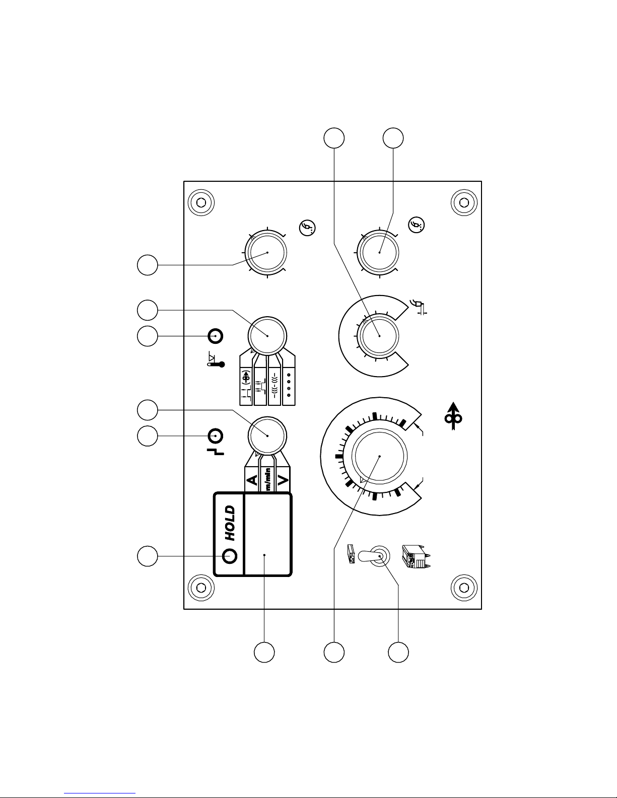
Front panel M 302 / M 352 / M 452 and M 552
Drahtvorschub
3
0
1
2
3
4
5
6
7
8
9
10
0.5
0.75
1.0
1.25
1.5
wire feed
1.75
2.0 sec.2.0 sec.2.0 sec.
1.751.75
1.51.5
1.251.25
1.01.0
0.750.75
0.50.5
2.0 sec.2.0 sec.2.0 sec.
2.0 sec.2.0 sec.2.0 sec.
1.751.751.75
1.751.751.75
1.51.51.5
1.51.51.5
1.251.251.25
1.251.251.25
1.01.01.0
1.01.01.0
0.750.750.75
0.750.75
0.75
0.50.50.5
0.50.50.5
Schweißzeit
Rückbrand
Schweißzeit
Rückbrand
wire burn backwire burn back
00
1
1
22
33
2
5
10
[m/min]
[m/min]
15
[m/min][m/min]
[m/min][m/min]
20
[m/min]
[m/min]
44
55
66
77
88
99
1010
timertimer
[m/min]
SchweißzeitSchweißzeit
timertimer
Schweißzeit
timer
SchweißzeitSchweißzeit
timertimer
Schweißzeit
timer
Schweißzeit
timer
0
10
00
1010
0
10
00
1010
1
2
11
22
3030
2525
2020
1515
1010
5
5
22
DrahtvorschubDrahtvorschub
wire feedwire feed
Drahtvorschub
wire feed
25
30
1
2
11
22
3
33
333
4
5
44
55
4
5
44
55
666
DrahtvorschubDrahtvorschub
wire feedwire feed
Drahtvorschub
wire feed
DrahtvorschubDrahtvorschub
wire feedwire feed
666
777777
8
9
88
99
8
9
88
99
RückbrandRückbrand
wire burn backwire burn backwire burn back
Rückbrand
RückbrandRückbrand
wire burn backwire burn backwire burn back
Rückbrand
303030
303030
252525
252525
202020
202020
151515
151515
101010
101010
5
5
222
222
5
555
wire burn back
Rückbrand
PausePause
intermissionintermissionintermission
Pause
PausePause
intermissionintermissionintermission
Pause
PausePause
intermissionintermissionintermission
Pause
0.5
0.5
0.75
1.0
1.25
1.5
1.75
2.0 sec.2.0 sec.2.0 sec.
1.751.75
1.51.5
1.251.25
0.5
0.5
1.0
0.5
0.75
0.5
1.0
0.5
0.750.75
0.50.5
2.0 sec.2.0 sec.2.0 sec.
2.0 sec.2.0 sec.2.0 sec.
1.751.751.75
1.751.751.75
1.51.51.5
1.51.51.5
1.251.251.25
1.251.251.25
1.01.01.0
1.01.01.0
0.750.750.75
0.750.75
1.51.51.5
1.51.51.5
1.51.51.5
2
1
456 7 8 9
10
11
E 3161-03
14

8th Adjustings
Front view
Pos. 1 Selector for wire setting
Pos. 2 Poti wire feed speed
Pos. 3 Display
Pos. 4 LED Hold
Pos. 5 LED (red) failure (watercooled units only)
Pos. 6 Switch display: A-, m/min-, or V-indication
Pos. 7 LED (yellow) overheating
Pos. 8 Switch operation mode
Pos. 9 Poti welding timer
Pos. 10 Poti wire burn back
Pos. 11 Poti intermission in mode interval welding
Poti wire feed (w/o. drawing) mounted at the wire feeder
9th Description Of The Functions
9th1 Adjustings
(see drawing front panel)
Pos. 1 Selector switch for wire feed
According to the position of this switch or the poti at the wire feeder pos. 2 or the poti
at the fornt panel of the unit (at compact version K) is activated.
Pos. 2 Poti mounted at the unit or at the wire feeder (w/o drawing) for the adjusting of the
wire feed speed. The scale is valid for both, the DV 25 and DV 30 always in m/min.
Pos. 3 Display
By means of switch pos. 6, the display shows or the welding current, or the wire
feed speed in m/min, or the welding current.
Pos. 4 LED „HOLD“ for the digital read out
enlighted after the welding Ö the last values during the welding for welding current
or welding voltage are shown in display pos. 3.
Pos. 5 LED (red) failure (watercooled units only)
enlighted if liquid is missing
Pos. 6 Switch Display-
See pos. 3
Pos. 7 LED (yellow) overheating
enlighted if the duty cycle has been exceeded
Pos. 8 Switch operation mode: 2-stroke, latch, interval, spot welding
Operation mode 2-stroke:
As long as the torch trigger is pressed the unit is welding
15

Operation mode latch:
1. stroke-trigger pressed – welding ON
2. stroke trigger released
3. stroke trigger pressed – welding OFF
4. stroke trigger released
Operation mode interval:
The wire is running and welding current is ON as long as the torch trigger is pressed.
The welding time is set by poti pos. 9, the intermission is set by poti pos. 11. The gas
comes out continously.
Operation mode spot welding:
The welding time is selected by poti pos. 9. Once the trigger is pressed down, the time
starts running and at the end the unit cuts operation automatically.
For this mode a special gas nozzle is available.
Pos.10 Poti wire burn back
Serves to set the stick out of the wire.
IMPORTANT: When operating a model 'W' with integrated water cooling system,
always check the filling of the water tank. When the machine is
stored or operated at temperatures below 0°C use 'MERKLE
coolant MKF' instead of water (part-no.: 107.822)
16

10th List of values
10th1 Voltage settings: M 302 K/D for mild steel
Range m/min. current (A) m/min. Current (A) m/min. current (A)
(fine /
coars)
wire 0,8 wire 1,0 wire 1,2
1 - 1 1,9 30 1,7 40
1 - 2 2,3 45 2,0 50
1 - 3 2,7 50 2,4 60 2,2 80
1 - 4 3,1 60 2,8 75 2,7 95
1 - 5 4,4 75 3,4 85 3,0 110
1 - 6 5,4 95 4,1 100 3,3 125
1 - 7 6,8 105 4,6 115 3,6 140
2 - 1 7,7 123 4,9 130 3,9 155
2 - 2 10,8 140 6,1 150 4,7 175
2 - 3 13,0 160 8,8 180 5,9 200
2 - 4 15,3 180 11,2 210 7,7 230
2 - 5 17,9 200 13,4 240 9,5 250
2 - 6 21,7 225 15,4 260 10,8 275
2 - 7 25,3 258 18,3 286 11,7 305
17

10th2 Voltage setting: M 352 K/D/KW/DW for mild steel
Range m/min. current (A) m/min. current (A) m/min. current (A)
(fine - coars) wire 0,8 wire 1,0 wire 1,2
1 - 1 2,3 40 1,7 50
1 - 2 2,5 45 1,8 53
1 - 3 2,8 50 2,0 57
1 - 4 3,2 60 2,2 60 2,0 80
1 - 5 3,5 65 2,6 63 2,2 90
1 - 6 3,8 70 2,6 67 2,3 100
1 - 7 3,9 2,7 70 2,4 110
2 - 1 4,0 80 2,8 75 2,6 120
2 - 2 4,5 85 3,1 80 2,8 123
2 - 3 5,0 90 3,4 90 3,0 127
2 - 4 5,5 90 3,7 100 3,2 130
2 - 5 5,7 95 3,9 105 3,3 135
2 - 6 6,0 100 4,0 110 3,4 140
2 - 7 6,8 110 4,1 120 3,5 145
3 - 1 7,6 120 4,8 130 3,8 150
3 - 2 8,2 125 5,2 140 4,3 160
3 - 3 9,0 132 5,8 150 4,8 170
3 - 4 9,8 140 6,4 165 5,5 190
3 - 5
11,0 150 7,0 172 5,9 200
3 - 6 13,0 160 8,0 180 6,3 215
3 - 7 14,3 170 9,0 190 6,8 230
4 - 1 15,8 180 10,2 210 7,6 245
4 - 2 17,9 190 11,6 220 8,1 255
4 - 3 19,0 200 13,3 230 8,8 270
4 - 4 20,5 215 14,3 240 9,4 284
4 - 5 22,8 230 15,2 255 9,9 295
4 - 6 24,5 250 16,1 270 10,6 310
4 - 7 25,0 260 17,7 280 11,3 328
18

10th3 Voltage setting: M 452 KW / DW for mild steel
Range m/min. current (A) m/min. current (A) m/min. current (A)
(fine - coars) wire 0,8 wire 1,0 wire 1,2
1 - 1 1,8 30 1,7 45
1 - 2 1,8 35 1,7 50
1 - 3 1,9 35 1,8 55
1 - 4 2,0 40 1,8 57
1 - 5 2,1 40 1,8 60
1 - 6 2,3 50 1,9 65
1 - 7 2,4 50 2,0 70
2 - 1 2,8 55 2,4 75 1,6 100
2 - 2 3,2 60 2,6 80 1,8 110
2 - 3 3,6 62 2,9 89 1,9 120
2 - 4 3,8 65 3,1 93 2,1 125
2 - 5 4,0 70 3,3 100 2,4 132
2 - 6 4,2 80 3,5 110 2,4 136
2 - 7 4,5 90 3,7 120 2,6 140
3 - 1 5,2 95 3,8 100 2,6 142
3 - 2 5,2 100 4,0 125 2,7 145
3 - 3 5,4 103 4,2 126 3,2 150
3 - 4 5,6 105 4,4 130 3,2 161
3 - 5 5,9 110 4,6 130 3,4 165
3 - 6 6,3 120 4,7 136 3,5 171
3 - 7 7,4 125 4,8 141 3,6 175
4 - 1 8,2 130 5,2 145 4,3 180
4 - 2 8,7 130 5,8 150 4,8 190
4 - 3 9,6 140 6,4 160 5,0 205
4 - 4 10,0 145 7,0 170 5,3 211
4 - 5 10,4 153 7,8 180 5,5 215
4 - 6 11,0 160 8,6 195 5,7 220
4 - 7 12,5 162 9,6 205 6,0 225
5 - 1 13,8 170 10,2 210 7,3 240
5 - 2 14,8 175 11,3 220 7,9 250
5 - 3 15,2 180 12,5 230 8,2 255
5 - 4 15,5 190 13,3 240 8,5 265
5 - 5 16,0 195 14,2 250 9,0 277
5 - 6 17,0 200 15,2 255 9,5 285
5 - 7 18,1 210 16,4 265 10,2 290
6 - 1 20,3 220 18,4 275 11,6 300
6 - 2 22,5 230 20,0 285 13,0 330
6 - 3 25,1 250 21,2 300 14,4 360
6 - 4 29,5 270 22,7 320 15,8 370
6 - 5 25,1 350 17,2 390
6 - 6 27,5 370 18,2 410
6 - 7 30,0 400 425 425
19

10th4 Voltage setting: M 552 DW for mild steel
Range m/min. current (A) m/min. current (A) m/min. current (A)
(fine / coars) wire 0,8 wire 1,0 wire 1,2
1 - 1 2,6 45 2,2 55
1 - 2 2,7 47 2,3 60
1 - 3 2,9 50 2,4 65
1 - 4 3,3 55 2,5 70
1 - 5 3,7 65 2,6 72
1 - 6 4,2 75 2,8 75
1 - 7 4,8 80 2,9 79
2 - 1 5,4 85 3,0 80 2,0 100
2 - 2 5,6 90 3,1 90 2,2 108
2 - 3 5,8 95 3,5 110 2,4 115
2 - 4 6,0 102 3,7 110 2,7 120
2 - 5 6,5 107 4,0 120 2,9 125
2 - 6 7,3 115 4,3 131 3,2 135
2 - 7 7,7 120 4,5 135 3,5 140
3 - 1 8,0 125 4,6 145 3,7 150
3 - 2 8,4 130 4,8 150 3,9 165
3 - 3 9,0 137 5,7 158 4,1 175
3 - 4 9,6 140 6,4 165 4,5 186
3 - 5 10,1 145 6,8 175 4,8 190
3 - 6 11,7 150 7,2 180 5,0 200
3 - 7 13,0 164 8,3 185 5,6 210
4 - 1 13,4 170 8,7 190 5,9 215
4 - 2 13,6 175 9,1 195 6,1 220
4 - 3 13,8 182 9,6 200 6,7 225
4 - 4 14,0 190 10,4 210 7,2 235
4 - 5 15,1 195 11,8 215 7,7 245
4 - 6 16,6 200 13,0 225 8,5 255
4 - 7 17,6 205 13,9 235 9,4 270
5 - 1 20,0 210 14,4 240 10,3 285
5 - 2 20,9 215 14,9 250 10,9 290
5 - 3 22,3 220 15,5 260 11,5 300
5 - 4 23,0 225 16,3 275 12,0 312
5 - 5 25,0 235 17,1 280 12,5 325
5 - 6 27,5 250 18,1 295 13,1 340
5 - 7 30,0 260 19,4 310 14,6 360
6 - 1 21,3 330 15,7 375
6 - 2 23,1 340 16,4 400
6 - 3 25,0 350 17,2 410
6 - 4 28,7 365 17,9 435
6 - 5 30,0 380 19,4 450
6 - 6 22,1 465
6 - 7 27,0 480
20

11th Options
11th1 Welding Stainless Steel
Exchange the parts according to the table listed in section “wire feeder” a Teflon liner
in the torch hose must be used. As gases we recommend mixtures of argon and
2.5 %CO2.
11th2 Welding Aluminium
Do not use wire diameters less than 1.0 mm. Max. length of the torch should not exceed 3 m.
Use Teflon liner in the torch hose. See section 'wire feeder' for exchange of parts for welding
of aluminium.
12th Aluminium Welding
1. Aluminium welding wire:
- Wire diameter 0.8 mm only with push pull torch
- Wire Al-Mg 3/5/4.5 Mn (1.0 mm), Al-Si, Al 99.5 (1.0 and 1.2 mm) torch lead max. 3 m
- For welding wire 1.6 mm we recommend a torch with a long torch head
- Do not store alu wire without the platic protection cover. Do not use alu wires with oxid.
2. Teflon liner:
- For wire 1.0 mm we recomend the carbon teflon liner 2.0 x 4.7 mm (part-no.
022.1.0586)
- For 1.2 and 1.6 mm carbon teflon liner 2.7 x 4.7 mm (part-no. 022.1.0588)
- The carbon teflon liner must be installed without any break from the contact tip to the
drive roller
- Fix the clamping nut at the Euro connector only by hand
3. Wire feeder:
- Exchange the brass guidance nozzle to a pvc guidance nozzle (between the two drive
rollers) DV-25: part-no. 012.0.0373, DV-30: part-no. 012.0.0269
- Exchange the insertion nozzle at DV-30 from brass to pvc (part.-no: 012.0 0267)
- Exchange the guidance core at DV-30 to pvc (part-no: 022.1.0237)
- Install the outgoing tube in the Euro connector to support the teflon liner
DV-20: part-no.012.0.0383
DV-25: part-no. 012.0.0369
DV-30: part-no. 012.0.0269
4. Wire feeding rollers:
- Exchage the two lower roller to aluminium rollers (U-groove), the rollers at the to may
remain pressure rollers without a groove.
5. Pressure of the rollers:
- Reduce the pressure to a minimum
- When the alu wire is stoped at the contact tip the rollers must turn without transporting
the wire.
6. Insertion of the wire:
- Insert the wire without a contact tip at the torch.
- Hold the torch cable straight, outherwise the wire could go through the line and the torch
lead.
21
 Loading...