

OPERATION MANUAL
MIG/MAG Welding Unit
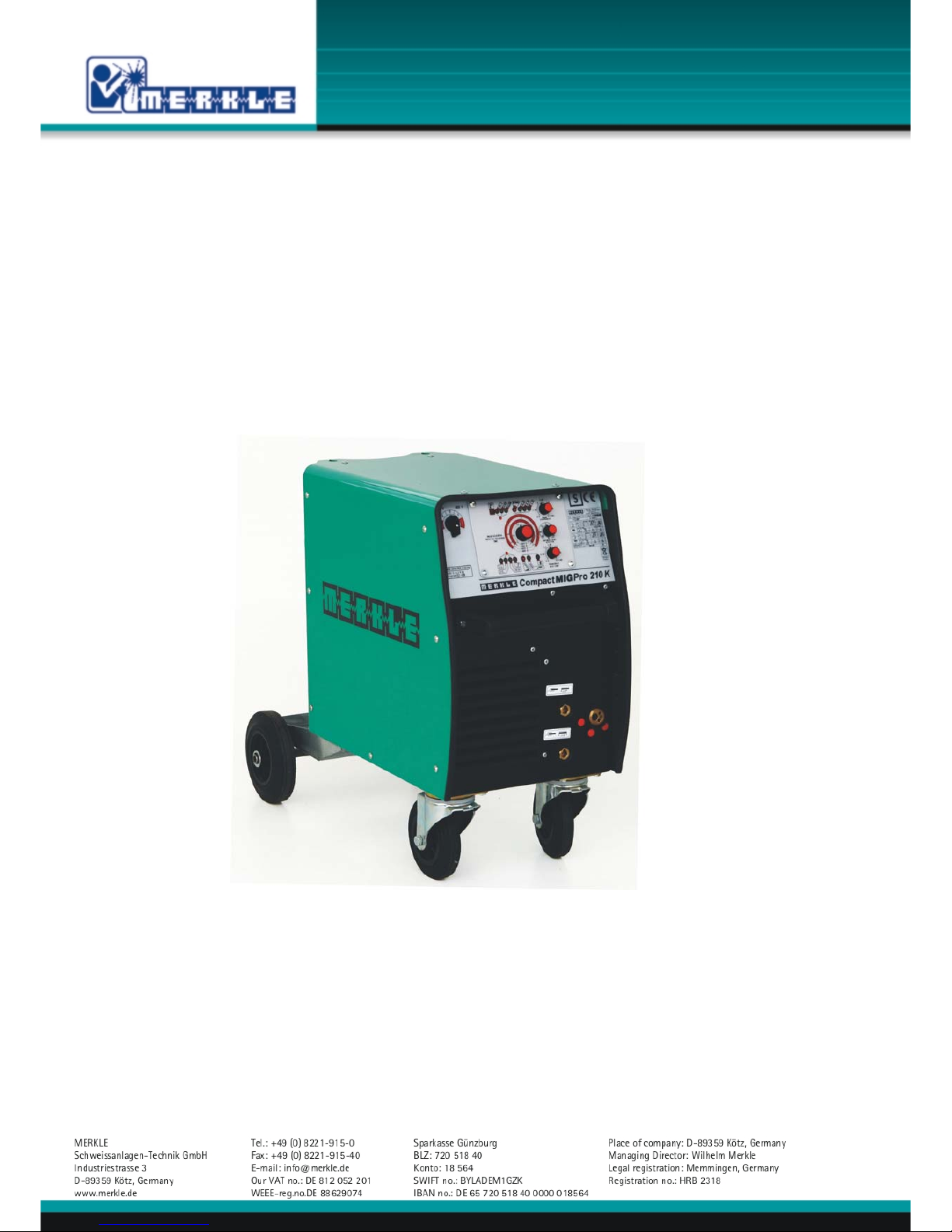
CompactMIGpro 210 K

2

1
Contents page
1. Security indications before introduction 3
2. Accident prevention regulations 3
Safety instructions 3
3. Duty cycle 5
4. Instructions to avoid interferences due to electromagnetic influences EMC 5
5. Technical Data 7
Synergic MIG/MAG welding unit, type CompactMIGpro 210 K 7
6. Start Up 9
Installation of the Machine 9
Main Supply 9
Welding Torch 9
Gas Connection 9
Wire Installation 9
7. Operation of the Welding Unit COMPACTMIGPRO 210 K K 11
8. General Information MIG/MAG Welding Units 12
Metal Inert Gas Welding (MIG) 12
Metal Active Gas Welding (MAG) 12
Protective Gases 13
Welding Wires 13
9. Maintenance 13
10. Cleaning 13
11. Trouble Shooting 13
Machine does not operate after switching on the main switch 13
Machine does not react on the torch switch 14
Machine has no or too low welding current 14
Problems with wire feeding 14
Problems with wire feeding and wire contacting 14
Welding quality is not good 14
Poor welding results 14
12. Spare part list COMPACTMIGPRO 210 K K 15

2
Front view 15
Left side view 17
Right side view 19
13. Wire Feeder model DV 25 19
Spare parts wire feeder model: DV-25 21
14. MIG/MAG Hand Welding Torch 23
MIG/MAG Hand Welding Torch Model SB/SBT 154 G, 25
15. Electrical components and wiring diagramm 27
Electrical components COMPACTMIGPRO 210 K K 27
Wiring diagramm COMPACTMIGPRO 210 K K 28
16. EU-Conformity Attestation COMPACTMIGPRO 210 K K 29

3
1. Security indications before introduction
The unit device is built after the recognized standards. Safe works are nevertheless only possible
if you read the operating instructions and the safety regulations contained in it entirely and
obey strictly. Install yourselves by trained staff of our establishments or appointed dealers.
2. Accident prevention regulations
The following accident prevention regulation is applied for welding with MIG/MAG welding unit,
type COMPACTMIGPRO 210 K K:
BGV D1 (earlier VBG 15) * Welding, cutting and allied processes
A copy of this regulation should be readily accessible in every welding shop. The stipulations of
this regulation are to be observed in the interests of safe and correct welding operation.
* Available from the trade association responsible or
Carl Heymanns-Verlag, Luxemburger Strasse 449, 50939 Cologne.
Safety instructions
This unit is manufactured according to the requirements and stipulations of EN 60974.1 / VDE
0544 part 1. BGV D1 (earlier VBG 15) of the trade association for precision engineering and
electrical engineering are as well valid.
1) In case of an accident, the cutting unit must be disconnected from the mains
immediately.
2) If electrical contact voltages arise, switch off the unit immediately, disconnect it from
the mains and proceed to inspection by a qualified electrician or by our Service
Department.
3) Before opening the unit, disconnect it from the mains supply.
4) Repair work may only be carried out by a skilled electrician or by our Service
Department.
5) Before the unit is put to operation, check it visually, as well as the torch and all cables
and connectors regarding possible external damages.
6) Personal protective equipment in accordance with DIN EN 175, DIN EN 379 and
DIN EN 169.
During the work, the welder’s body must be completely protected against radiation and
burns by means of protective clothing and face protection. Long gloves, aprons and
welding shields with welding filters conforming to DIN EN 470-1 and BGR 189
must be worn.
Synthetic clothing are excluded. Shoes must be closed, not opened (due to spatters). If
necessary, protective headwear must be worn (e.g. for overhead welding). If cover
glasses are used, these must be in accordance with the norms specified above.
As additional protection for the eyes against UV radiation, safety goggles with side
shields and corresponding face protection in accordance with BGR 192 and BGI 553
must be worn.
Accident prevention regulation BGV D1 § 27 stipulates that it is the responsibility of the
employer to provide suitable personal protective equipment, while § 28 stipulates that it
is the responsibility of the insured to wear suitable clothing.

4
7) Protection when welding under increased electrical risks
Welding rectifiers and welding power sources which can optionally be used for either
direct or alternating current must be marked "S" in accordance with EN 60974-1 and
BGI 534.
Use insulating materials to protect you against contact with electrically conductive parts
and damp floors. Wear dry, undamaged work clothing, long gloves and footwear with
rubber soles. Ventilate rooms, install extraction systems if required, and wear respiratory
protective equipment if necessary (see Procedural instructions BGV D1 § 27 and BGI 533,
Section 5).
8) In order to prevent stray currents and the effects thereof (e.g. destruction of electrical
protective ground conductors), the welding return cable (workpiece cable) must be
connected directly to the workpiece to be welded or to the table (e.g. welding table, gridtype welding table, workbench) supporting the workpiece (see BGV D1 § 20). When
installing the ground connection, assure that there is a good electrical contact (remove
rust, paint, etc.).
9) During welding pauses, the welding torch is to be laid down on an insulated surface or
hung up in such a way that it is not in contact with the workpiece and its support
connected to the welding power source (see § 20 BGV D1).
In the case of longer work pauses, the welding unit must be switched off and the gas
cylinder valve must be closed.
10) The shielding gas cylinder must always be protected against tumbling downing using a
safety chain.
11) Under no circumstances the unit may be put into operation while it is opened
(e.g. for repair work). Apart from the safety regulations, sufficient cooling of the
electrical components provided by the fan cannot be guaranteed.
12) In accordance with BGV D1 § 5, people in the vicinity of the arc must also be informed
of the hazards and protected against them. Safety partitions (“welding safety curtains”)
must be erected in accordance with DIN EN 1598.
14) No welding work may be carried out on containers in which gases, fuels, mineral oils or
similar substances have been stored Öeven if they have been empty for a long timeÕ
(risk of explosion). See § 31 of accident prevention regulation BGV D1.
15) Welds which will be subjected to high loads and which need to meet specific safety
requirements may only be carried out by specially trained and qualified welders.
15) Never bring the torch close to your face.
16) In areas at particularly high risk of fire, the welder must obtain a welding permit and
have this on his person throughout the duration of the welding work. On completion of
welding, a fire-guard must be delegated to ensure fire protection.
17) Ventilation measures must be applied in accordance with BGI 553, Section 9.
18) The hazard to eyesight must be indicated by means of a sign at the work site "CAUTION!
Do not look into the arc!".

5
3. Duty cycle
The duty cylce measurings have been carried out in accordance with
EN 60974-1 / VDE 0544 part 1 (10 min working period).
60% duty cycle means:
After a 6 min. welding period a 4 min welding pause must be respected. The electrical
components are thermally protected against overheating.
4. Instructions to avoid interferences due to electromagnetic influences EMC
The welding unit has been manufactured in accordance with the requirements of guideline
EN 50199 regarding electromagnetic compatibility. It is nonetheless the responsibility of the
user to ensure that the welding equipment is installed and operated in accordance with the
manufacturer’s instructions. If electromagnetic interference is detected, it is the responsibility of
the user of the welding equipment to find a solution with the technical assistance of the
manufacturer. In some cases, it may be sufficient simply to ground the welding current circuit.
In other cases, it may be necessary to build a complete shield for the welding power source and
workpiece using the input filters. In all cases, electromagnetic interference must be reduced to
avoid any possible malfunctions.
Note: For safety reasons, the welding current circuit may or may not be grounded. No
modifications may be made to the grounding without the approval of an expert who is able to
determine whether the changes might increase the risk of accidents, e.g. by allowing parallel
welding current return paths which could destroy the ground conductors of other equipment.
Further instructions are contained in TEC 974-XX "Arc welding equipment – installation and
use".
a) Evaluation of the installation site
Before installing the welding equipment, the user must evaluate potential
electromagnetic problems in the vicinity. The following must be taken into
consideration:
a. Other power cables, control cables, signal and telecommunication cables above, below
and next to the welding equipment
¾ Radio and television transmitters and receivers
¾ Computers and other control devices
¾ The health of people in the vicinity, e.g. use of heart pacemaker and hearing aids
¾ Calibration and measuring equipment
¾ Interference immunity of other devices in the vicinity. The user must ensure the
electromagnetic compatibility of other devices used in the vicinity. This may require
additional safety measures.
b) Procedures to reduce emitted interference
1) Mains supply
Welding equipment is to be connected to the mains in compliance with the
recommendations of the manufacturer. If interference occurs, it may be necessary to
take additional precautions, e.g. filters for the mains connection. Make sure that the
power cable of welding equipment is installed in a fixed position shielded by means of a
metal conduit or similar. The entire length of the shield must be electrically connected.
The shield must be connected to the welding power source in the way to obtain a good
electrical contact between the metal conduit and the housing of the welding unit.

6
2) Maintenance of the welding equipment
Welding equipment must be maintained regularly in accordance with the
recommendations of the manufacturer. All access and service doors and covers must be
closed and fastened securely when the welding equipment is in operation. No
modifications whatsoever may be made to welding equipment with the exception of
modifications and adjustments specified in the manufacturer’s operating instructions.
3) Welding cables
Welding cables should be kept as short as possible and routed close together on or near
the floor.
4) Equipotential bonding
It is advisable to interconnect all metallic parts in and next to the welding equipment.
Metallic parts connected to the workpiece can, however, increase the risk of the welder
receiving an electric shock by touching these metallic parts and the electrode
simultaneously. The welder must be electrically insulated against all these connected
metallic parts.
5) Grounding the workpiece
If the workpiece is not connected to the ground for electrical safety reasons, or due to
the size and position of the workpiece, e.g. steel structure or outer wall of a ship,
grounding the workpiece may in some cases, but not all, reduce emitted interference. It
must be ensured that grounding the workpiece will not increase the risk of accidents for
the user and cannot cause the destruction of other electrical equipment. If necessary,
the grounding of the workpiece must be carried out by means of a direct connection to
the workpiece. In countries where a direct connection is prohibited, the connection must
be made by means of suitable reactors, selected in accordance with national regulations.
6) Shielding
Selective shielding of other cables and devices in the vicinity can reduce interference
problems. For special applications, it may be worth considering shielding the entire
welding system.

7
5. Technical Data
Synergic MIG/MAG welding unit, type CompactMIGpro 210 K
Primary:
Voltage 1 x 230 V 1 x 400 V
Frequency: 50/60 Hz 50/60 Hz
Continuous power: 2.9 kVA 3.6 kVA
Continuous current: 0.73
cos phi (150 A): 0.73 0.76
Secondary:
Open circuit voltage: 42 V 42V
Welding voltage: 15-22.5 V 15-24.5 V
Welding current: 25-170 A 25-210 A
duty cycle 35 %: 170 A (10 min) 210 A (10 min)
duty cycle 60 %(40°C): 90 A (10 min) 110 A (10 min)
Protection class: IP 21
Insulation: H
Cooling: AF
Mains switch: 230 V range 1 + 2
400 V range 1 + 2
Program selection: tip control and LEDs for
2-stroke/4-stroke/stich/spot w.
Remote control: tip control and LEDs for
setting at the TEDAC torch/
setting at the machine
Material selection: tip control and LEDs for
mild steel/stainless steel/alu
Wire selection: tip control and LEDs for
diameter 0.6/0.8/1.0 mm
MIG brazing: special program f. MIG brazing
Energy setting: potentiometer / TEDAC torch
Wire trim: potentiometer
Wire burn back: installed
Spot welding time: potentiometer
Intermission time: potentiometer
Temperature overload: LED
Integr. Functions: - wire feed automatic
- safty cut-off in 4-stroke
- wire soft start
- crater filler
- welding programs
Power source: thyristor
Rectifier: silicon press-in diodes
Choke: 2 sockets for welding and
MIG brazing

8
Norm: EN 60974-1 "S" / CE
Torch cooling: gas
Weight: 75 kg
Dimensions l x w x h: 800 x 460 x 620 mm
Gas bottle holder: for 10, 20 l cylinders
Mains supply cable: 5 x 1.5 mm², 5 m long
with plug 3 x 400 V / 16 A
Gas hose 2 m long
Socket 35 mm²: for earth lead
Wire feeder: compact, model DV-26
Voltage: 26 V-DC
Wire feed motor: DC motor with worm gear drive
0.7 - 25 m/min.
Gear: 4-roller-drive DV-25
Reel hub assembly: D 300/15 DIN 8559
Torch connection: Euro connector
Standard wire equip.: mild steel 0.8 mm
Standard accessoreis:
Earth lead 25 mm², 4 m long part.- nr. 022.1.0400
with plug and earth clamp
Regulator argon/CO2, single stage part.- nr. 012.0.0300
Accessories:
Coupling 230/400 V part.- nr. 005.0.1869
Adapter for wire spool part.- nr. 029.0.0104
MIG/MAG hand welding torch part.- nr. 022.1.0858

9
6. Start Up
Installation of the Machine
Place the machine at least 0.80 m from a wall etc. to guarantee the cooling air can go
through the unit. The room temperature should not exceed 40°C.
The room were the unit is placed should have a low degree of humidity
(max. 50 % at 40°C, max. 90 % at 20° C).
The unit has passed the quality control in accordance with IP 21.
The air in the surroundings must be free from extreme quantities of dust, free from acides and
corrosive gases etc. Otherwise use air filters.
Main Supply
The main supply must be connected by a trained person. The main supply voltage is displayed on
the front or rear panel of the machine. A connection to ground (GND) must be done.
Welding Torch
Connect the torch to the Euro-connector.
Gas Connection
Place the gas bottle on the gas bottle holder and secure it with the safty chain. Remove
the cap and open the bottle momentarily to purge the valve. Install the regulator on the
bottle valve. Connect the gas hose from the machine to the pressure reducer. Slowly open
gas valve and set the gas flow.
Wire Installation
Place the wire spool over the wire drive. Loosen the end and cut off the bent end section.
Hold the wire to prevent unwinding of the spool. Open the lightning lever and lift the pressure
finger. Feed the wire into the wire feed guide. Push the wire forward onto the
wire drive roller grooves. Close the lightning lever and switch on the machine.
Check the wire feeding: Place your hand 10 cm in front of the contact tip. Let the wire run
into your hand. If the wire is running, the pressure of the drive rollers is o.k.

10
Front view

11
7. Operation of the Welding Unit COMPACTMIGPRO 210 K K
The machine is operating in synergic mode: welding voltage, welding
current and wire feed speed are adjusted with only one buttom (Pos. 5) or
by means of the TEDAC torch.
Front View
(see figure)
Pos. 11 main switch with two steps for 400 V (380-415 V) and two steps
for 230 V (220-240 V)
step 1: reduced maximum energy for welding of thin metal sheeds
step 2: full energy
Pos. 15 selector: 2-stroke, 4-stroke, interval, spot welding
2-stroke-operation - LED 14 is on:
Press the torch switch, the wire is running with about 30 of the adjusted wire
feed speed. The gas flow is switch on and the no-load voltage is applied to the
contact tip.
If the wire has no contact to the workpiece within 5 sec., the gas valve and the
no-load voltage are switched off. The wire feed speed is switched to 10 m/min for
inserting the wire into the wire core (wire feed automatic).
Release the torch switch and press it again to start the welding process.
4-stroke-operation - LED 13 is on:
1st stroke: torch switch pressed down - the wire is running with a reduced speed
(30 of the welding wire feed speed). As soon as the wire contacts the
workpiece the wire feed speed is switch to the welding wire feed speed
(wire soft start).
If there is no contact of the wire to the workpiece within 3 sec. while the
torch switch is pressed down, the machine automatically stops the operation
(safty cut-off).
2nd stroke:
torch switch is released - welding with selected energy
3rd stroke: torch switch is pressed down: the welding current is automatically
sloped down from the selected welding current to the minimum current.
4th stroke:
torch switch is released: welding current is switch off.
Interval operation - LED 12 is on:
With the var. resistors Pos. 2 and Pos. 4 the welding and intermission times are
selected (range: 0.5 - 2.0 sec.) As long as the torch switch is pressed down, the
interval welding process is operated.
Spot welding - LED 10 is on:
With the var. resistor Pos. 2 the spot welding time is selected (range: 0.5 - 2.0
sec.).
Pos. 9 Selection of the energy control
LED 6 is on: control of the energy directly at the machine with vac. resistor
Pos. 5. Scalles are calibrated in material thickness (mm).

12
LED 8 is on: control of the energy directly at the TEDAC welding torch.
Var.resistor Pos. 5 has no function.
Pos. 16 Selection of the welding wire
LED 18: 'St' -mild steel
LED 19: 'CrNi' - stainless steel
LED 20: 'Al' - aluminum and aluminum alloys
Pos. 21 Selection of the diameter of the welding wire
LED 22: 0.6 mm
LED 23: 0.8 mm
LED 24: 1.0mm
After switching off and on the welding unit the last selected parameters are
automatically recalled.
Pos. 3 control of wire trim
+/- 30 change of the automatically selected wire feed speed
Pos. 17 temperature of the welding unit is too high: welding current is switch off. Wait
for cooling down of the machine by the fan and continue welding after LED 17
is off.
Pos. 25 Euro-connection for the welding torch
Pos. 28 connector for earth lead (MIG/MAG welding)
Pos. 29 connector for earth lead (MIG brazing)
8. General Information MIG/MAG Welding Units
MIG/MAG welding is a system where the welding wire is the carrier of the electric arc.
Surrounding the contact tip (wire feed nozzle) is the gas nozzle, that emits the protective gas.
The welding bead is protected in this way from oxygen contamination.
Metal Inert Gas Welding (MIG)
In this technology inert gases are used. Mostly used are argon, helium, and mixtures of these
components. These gases do not react with other materials, they are inert. They are manly used
for welding aluminium, copper, titanium or other non ferrum metals.
Metal Active Gas Welding (MAG)
For MAG welding gases like CO2, argon, and mixtures of these components are
used. For special purposes also mixtures of C02, argon and oxygen can be used. Mild steel and
stainless steel is welded with theses gases.

13
Protective Gases
The gas flow is depended on several parameters:
- gas density
- material of work piece
- distance gas nozzle to work piece
- diameter of gas nozzle
- geometry of weld
For welding steel and stainless steel the gas flow is in the range of about 8 to 16 I at welding
currents of 40 -400 A. For welding aluminium the gas flow is about 30 % more.
Welding Wires
Different diameters of welding wires are available:
0.6 / 0.8 / 0.9 / 1.0 / 1.2 / 1.6 / 2.4 mm.
9. Maintenance
The machine should be cleaned in regular intervals to guarantee a proper operation. The length
of the cleaning interval depends on the operation time, surrounding atmosphere etc.
IMPORTANT: Before opening the machine disconnect the main supply!
10. Cleaning
Welding unit: Open the side covers. Remove dust from all parts of the
machine.
Welding torch: Control the welding torch after welding of 50 kg wire.
Remove, clean and replace the wire core. Clean with a cleaning
solvent. Blow dry with compressed air. When replacing the wire
core, insure that there are no kinks. The gas nozzle must be
sprayed with a silicon-free spray to prevent the weld spatters
from sticking to the nozzle. The contact tip is a consumable item
and must be replaced as required.
Attention: Do put oil to the wire core or the drive roller on the
wire feed unit.
11. Trouble Shooting
Machine does not operate after switching on the main switch
a) Check main supply
b) Check main fuses

14
Machine does not react on the torch switch
a) Problem at the torch switch
b) Check internal fuses
Machine has no or too low welding current
a) Bad or no contact at the earth lead
b) Torch hose completely or partially broken
c) Problem with thyristor in the machine
d) Only 2 main phases are connected, check main fuses
Problems with wire feeding
a) Wrong diameter of the contact tip or contact tip must be changed.
b) The liner is extremely dirty.
c) Kinks in the liner.
d) Wrong diameter of the liner.
e) Check the pressure of the rollers.
Problems with wire feeding and wire contacting
a) Hole in the contact tip has wrong diameter or contact tip must be changed.
b) Wire core is extremly dirty.
c) Kinks in the wire core.
Welding quality is not good
a) No or too low gas flow
b) Air is mixed into the protective gas. Open gas valve and close it again. Gas pressure
must remain in the gas hose. Check at the regulator.
c) Gas nozzle or tip holder are covered with spatters. Gas flow is not o.k.
d) Tip holder is not fixed properly. Air is mixed into the protective gas via the wire
e) Extremly oxidated workpiece.
f) Air is comming to the welding area because of wind.
Poor welding results
a) Protective gas is missing
b) Air is mixed into the protective gas. Open gas valve and close it again. Gas pressure
must remain in the gas hose. Check the regulator
c) Gas nozzle or tip holder are covered with spatters. Gas flow is not ok.
d) Tip holder is not fixed properly. Air is mixed into the protective gas via the wire
e) Extremely oxidated work piece.
f) Air is coming to the welding area because of the wind.
f) Wrong size of or used rollers are mounted.
g) Mechanical resistance of the welding wire is too high.

15
12. Spare part list COMPACTMIGPRO 210 K K
Front view
Pos. Description electrical. part no.
1 side cover left 005.0.0977
2 knob 003.0.1503
3 knob 003.0.1503
4 knob 003.0.1503
5 knob 003.0.1505
9/15/16/21 switch (mounted on pc-board)
11 main switch Q1 001.0.0058
6/7/8/10/12/13/14/17/18/19/20/22/23/24
LED (mounted on pc-board)
25 euro- connector 002.0.2875
26 front panel 011.0.1039
27 side cover left 005.0.0978
28 socket for earth lead 001.0.1101
29 socket for earth lead 001.0.1101

16
Left side view
30
31
32
33
34
35
36
37
38 39 40 41
42
444347
46
45

17
Left side view
Pos. Description electrical. part no.
30 power supply cable 5x1.5 mm2, 5,5 m 009.0.1700
31 plugCEE 16 A 012.0.1700
32 cable fixture 001.0.0702
33 main transformer EN 210 A T1 001.0.1918
with thermical switch F6 001.0.0408
34 fan 230 V –AC M2 001.0.1323
35
choke EN 210A L1 108.848
36
gas hose
37 gas valve 42 V – AC Y1 002.0.1602
38 control transformer T2 001.0.1819
prim.: 400V/230V
sek. 9V-42V-29V-18V- 9V
39 current converter T3 010.0.1604
with resistor 47 Ohm-0,5 W R5 030.0.1133
40 triac V2 001.0.0189
41 pc-board ME-MAG 20-0/Z A2 003.0.0179
42 resistor 15 Ω -9 W R1/R2 020.1.1090
43 pc-board ME-MAG 20.0 A1 003.0.0178
with E-prom M 20211 CU 16.10.2002
insulating board 002.0.0139
44 capacitors 8 x 10000 µF - 63 V C1 010.0.1900
45 rectifier 210A V1 001.0.0249
46 with thermical switch 90° C F7 001.0.0207
47 varistor S 14K60 R1 010.0.1909
pc-board ME-EMV-1.3 (not shown) A3 003.0.0084

18
Right side view
50
55
60
59 a-e
62
64
65
57
58
53
56
61
63

19
Right side view
Pos. Description electrical. part no.
50 swivel wheel 005.0.1205
53 wire feeder DV 25, complete 002.0.2850
motor M1 002.0.2630
capacitor 0,1 µF -1000V C9/C10/C11 001.0.0415
55 handle 005.0.1466
56 cover sheed 005.0.0969
57 insulator 002.0.2954
cap red 003.0.1522
58 insulation plate 002.0.2876
inside insulation 012.0.0285
59a- fuse holder 003.0.1207
59e with cap 003.0.1206
59a fuse 1 At F1 003.0.1212
59b fuse 1 At F2 003.0.1212
59c fuse 0,5 At F3 003.0.1220
59d fuse 0,5 At F4 003.0.1220
59e fuse 3,15 At F5 003.0.1236
60 wire spool holder 002.0.2821
61 middle sheed 005.0.0974
62 safty chain 005.0.0421
63 machine body 005.0.0972
64 gas bottle holder, complete 005.0.0979
65 wheel 005.0.0461
13. Wire Feeder model DV 25

20
1
2
3
4
5
6
7
8
9
10
11
12
13 15
16
17
19 20 21 23
242526
27
28
29
30 32
33
22 34
14
31
E 2715-39
39
Drahtvorschubgetriebe DV-25
3518

21
Spare parts wire feeder model: DV-25
(If spare parts for the wire feeder are needed, always indicate number of the relative
positon and part number)
Pos Description _Part No._
Wire feed gear complete 002.0.2850
with motor and wire feed rollers
1 gear flange (brass part) 002.0.2875
gear flange (complete) 012.0.0287
(Euro connector preassembled)
2 lentil flat-head screw 090.0.0825
3 insulation bush 002.0.2877
4 knurled screw M 4 x 20 090.0.1002
5 bolt (roller) 002.0.2859
6 bolt 002.0.2864
7 rocking bar 002.0.2865
8 cylindrical pin 090.0.0571
9 thread pole M 8 x 90 002.0.2863
10 knurled nut 002.0.2862
11 compression spring 002.0.2690
12 pressure piece 002.0.2861
13 thread case 002.0.2860
14 rocking bar 002.0.2866
15 bullet button 002.0.2856
16 pvc liner 012.0.0377
17 permanent magnet motor 24 VDC 002.0.2630
18 hexagon screw 090.0.4335
washer 090.0.1208
spring ring 090.0.1408

22
Pos Description _Part No._
19 insulation plate 002.0.2876
20 gear insulation 012.0.0285
21 gear angle 002.0.2874
22 sheet steel protection 002.0.2870
23 outgoing nozzle (brass) 6 x 2 x 48 002.0.0367
Outgoing tube (brass) for alu/stainless steel 012.0.0369
6 x 0.6 x 45
24 bolt (roller) 002.0.2873
25 for mild steel/stainless steel:
drive roller with groove V ∅ 0,6 mm 002.0.2879
drive roller with groove V ∅ 0,8 mm 002.0.2880
drive roller with groove V ∅ 1,0 mm 002.0.2881
drive roller with groove V ∅ 1,2 mm 002.0.2882
for aluminium:
drive roller ∅ 0,8 mm alu 002.0.2884
drive roller ∅ 1,0 mm alu 002.0.2885
drive roller ∅ 1,2 mm alu 002.0.2886
drive roller ∅ 1,6 mm alu 002.0.2887
26 knurled screw M 4 x 10 090.0.1001
27 fastener 002.0.2869
28 drive pinion 002.0.2871
29 guidance nozzle (brass) for steel 5 x 1,5 x 40 002.0.2867
guidance nozzle for alu/stainless steel 012.0.0373
(pvc) 5 x 1,5 x 40
30 knurled screw 002.0.2857
31 pressure roller 002.0.2878
32 screw (brass) 025.1.1610
33 incoming nozzle 002.0.2891
34 retaining ring 002.0.2858
39 edge protection rubber (0,3 m) 001.0.0820

23
14. MIG/MAG Hand Welding Torch
Model SB/SBT 154 G
Technical Data:
Mixed gas: 150 A 60 % duty cycle
CO2: 180 A 60 % duty cycle
Wire diameter:
Solid wire: 0.6 – 0.8 mm ∅
Alu wire: 0.8 – 1.0 mm ∅
Weight: approx. 930 g/1 m H
The data are corresponding to (U = 14 + 0.05 x I)

24
MIG/MAG Hand Welding Torch
Model SB/SBT 154 G, gas cooled

25
MIG/MAG Hand Welding Torch Model SB/SBT 154 G,
gas cooled
Pos. Description Part No.
MIG/MAG hand welding torch, model SB 154 G, 3 m 022.1.0738
MIG/MAG hand welding torch, model SB 154 G, 4 m 022.1.0739
MIG/MAG hand welding torch, TEDAC, model SBT 156 G, 3 m 022.1.0752
MIG/MAG hand welding torch, TEDAC, model SBT 156 G, 4 m 022.1.0753
Standard wire equipment: mild steel 0.8
Spare parts and consumables:
1 Torch neck SB/SBT 154 G 022.1.0734
2 Tip adapter, short, SB/SBT 154 G VE 10 St 022.1.0176
3 Contact tip 0.6 mm VE 10 St 022.1.0177
3.1 Contact tip 0.8 mm VE 10 St 022.1.0170
3.2 Contact tip 1.2 mm VE 10 St 022.1.0182
4 Gas nozzle SB/SBT 154 G VE 10 St 022.1.0095
5 Spot welding gas nozzle SB/SBT 154 VE 10 St 022.1.0096
10 Handle MIG, complete 105.016
with trigger and cover cap
13 Cable support for TEDAC handle 022.1.0774
14 Trigger for MIG/MAG torch 022.1.0796
15 Micro switch MIG/MAG torch 022.1.0797
16 Spring for switch VE 10 St 022.1.0131
Only for SBT 154 G:
17 TEDAC pc-board ME-BE-10.0 022.1.0800
incl. slide switch and micro switch
19 Complete cable assembly SB/SBT 154 022.1.0316
3 m, with Euro connector,without torch, without liner
19.1 Complete cable assembly SB/SBT 154 022.1.0317
4 m, with Euro connector,
without torch, without liner
20 Euro connector gas cooled, 025.1.1350
incl. cable support and
adapter nut
21 Brass body for MIG Euro connector 025.1.1401
22 Euro adapter nut 025.1.0300
23 Liner nut VE 10 St 025.1.1301
24 Cable support at Euro connector 025.1.1300
25 Liner for steel (blue) 022.1.0246
0.6 - 0.8 (1.0) mm, 3 m long
25.1 Liner for steel (blue) 022.1.0247
0.6 - 0.8 (1.0) mm, 4 m long

26
Pos. Description Part No.
26 Teflon liner for alu and stainl.st. 022.1.0586
0.8 - 1.2 mm, 3 m (red, 2.0 x 4.0)
27 Collet for teflon liner 2.0x4.0 mm VE 10 St 107.544
28.1 Outgoing and guidance nozzle pvc, 012.0.0384
DV-20, for alu and stainless steel
28.2 Outgoing nozzle pvc, DV-25 103.001
for aluminium and stainless steel
Only for SB 154 G:
30 Cover cap for TEDAC handle 022.1.0604
* max. length of torch lead for alu: 3 m

27
15. Electrical components and wiring diagramm
Electrical components COMPACTMIGPRO 210 K K
electr. Description part no.
A1 pc-board ME-MAG 20.0 003.0.0178
with E-prom MAG-20210 (COMPACTMIGPRO 210 K K)
insulating board 002.0.0139
A2 pc-board ME-MAG-20.0/Z 003.0.0179
A3 pc-board ME-EMV-1.3 003.0.0084
C1-C8 capacitors 8x10000 uF 63 V 010.0.1900
C9-C11 capacitor 0.1 uF -1000 V 001.0.0415
F1 fuse - control transformer prim. 400 V -1 A 003.0.1212
F2 fuse - control transformer prim. 400 V -1 A 003.0.1212
F3 fuse-fan 230V-0.5 A 003.0.1220
F4 fuse - pc-board 42 V - 0.5 A 003.0.1220
F5 fuse - motor 29 V - 3.15 A 003.0.1236
F6 thermical switch - main transformer 003.0.1236
F7 thermical switch - rectifier 90° C 001.0.0207
L1 choke EN 211 108.848
M1 wire feed motor 24 V – DC 002.0.2630
M2 fan 230V-AC 001.0.1323
Q1 main switch 001.0.0058
R1-R2 resistor 15 Ω - 9 Watt 020.1.1090
R3 var. resistor 10 kOhm – energy 001.0.0545
R4 var. resistor 10 kOhm - wire trim 001.0.0545
R5 resistor 47 Ohm - 0.5 W 030.0.1133
R6-R7 varistor S14K60 at the rectifier 010.0.1909
T1 main transformer EN 210 A (COMPACTMIGPRO 210 K K)
001.0.1918
T2 control transformer prim. 400V/230V 001.0.1819
sec. 9V/42V/29V/18V/9V
T3 current converter 010.0.1604
V1 rectifier 210 A 001.0.0249
V2 triac 001.0.0189
X1 euro-connection 012.0.0287
X2-X3 bush 012.0.1509
X1/A1 socket 6-pol. 015.0.0407
X2/A1 socket 18-pol. 015.0.0406
X3/A1 AMP pin socket 4-pol. 016.0.0113
X1/A2 AMP pin socket 2-pol.
X2/A2 socket 10-pol. 015.0.0412
X3/A2 socket 4-pol. 015.0.0409
X4/A2 socket 8-pol. 015.0.0410
X5 socket for power supply cable
Y1 gas valvel 42 V – AC 002.0.1602

28
Wiring diagramm COMPACTMIGPRO 210 K K
29
16. EU-Conformity Attestation COMPACTMIGPRO 210 K K
EU – Conformity Attestation
Description of the unit: MIG/MAG welding unit
Model: COMPACTMIGPRO 210 K K
The above mentionned unit complies with the following European Regulations:
EU-Low Voltage Regulation 73/23/EWG
EU-Electromagnetic Compatibility 89/336/EWG
In case of any modifications, incorrect repairs not exclusively authorized by Merkle, this
attestation looses its valdity.
Applied norms EN 60974 - 1 / IEC 974 - 1 / VDE 0544 part 1
EN 60204 - 1 / IEC 204 - 1 / VDE 0113 part 1
EN 50199
Kötz, July 13th, 1998
Wilhelm Merkle, Generalmanager
Merkle Schweißanlagen-Technik GmbH

30
Notes:

31

32
2. Edition 2003 October 06th. 2003
Technical changes reserved
 Loading...