

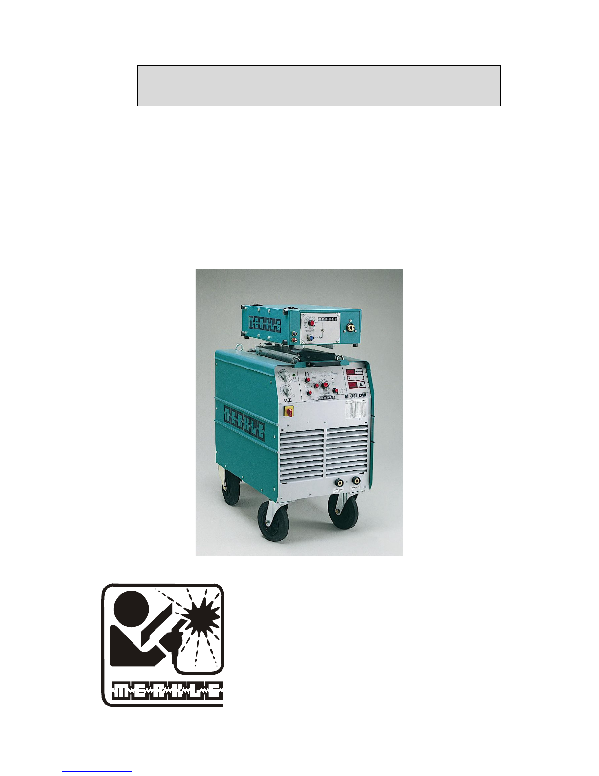
Operation Manual
MIG-MAG Welding Unit
M 301 K/D
M 351 K/D/KW/DW
M 451 KW/DW
M 551 DW
MERKLE
Schweissanlagen-Technik GmbH
Industriestrasse 3
D-89359 Koetz,
Tel.: ++49-8221-915-0
Fax: ++49-8221-915-40
www.merkle.de
Germany

.

Content page
1st
Security indications before introduction 3
2nd Accident prevention regulations 3
2nd1 Safety instructions 3
3rd Duty cycle 5
4th
Instructions to avoid interferences due to electromagnetic influences EMC 5
5th
Technical Data 7
5.1 Model: M 301 K/D M 351 K/KW/D/DW 7
5.2 Model: M 451 KW/DW M 551 DW 8
6th
General Information MIG/MAG Welding Units 9
6th1 Metal Inert Gas Welding (MIG) 9
6th2 Metal Active Gas Welding (MAG) 9
6th3 Protective Gases 9
6th4 Welding Wires 9
6th5 Duty cycle 9
7th
Installation 9
7th1 Main Supply 9
7th2 Earth Lead (Work Cable) 9
7th3 Welding Torch 10
7th4 Gas Connection 10
7th5 Wire Installation 10
8th
Installation of the Machine 10
9th
Options 10
9th1 Welding Stainless Steel 10
9th2 Welding Aluminium 10
10th Maintenance 10
11th Cleaning 10
12.
MIG/MAG Series M 301/351/451/551 11
13th Wire feeder systems 11
13th1 Spare parts wire feeder model: DV-25 13
13th2 Spare parts wire feeder model: DV-30 16
1

14th Operation of the Unit: 21
15th Ein adjust worth 22
15th1 Voltage settings: M 301 K/D for mild steel 22
15th2 Voltage setting: M 351 K/D/KW/DW for mild steel 23
15th3 Voltage setting: M 451 KW / DW for mild steel 24
15th4 Voltage setting: M 551 DW for mild steel 25
16th Trouble Shooting 26
16th1 Machine does not operate after switching on the main switch 26
16th2 Machine does not react on the torch switch 26
16th3 Control LED (red) is on 26
16th4 Water pump is running, control LED (red) is on 26
16th5 Control LEDs (yellow) and (red) are on 26
16th6 Machine has no or too low welding current 26
16th7 Welding quality is poor 26
16th8 Problems with wire feeding and wire contacting 26
16th9 Burning of the liner 26
17th Spare part list and wiring diagram 27
17th1 Spare part list M 301 K/D 27
17.2 Wiring diagramm M 301 K/D 28
17th3 Spare part list M 351 K/D/KW/DW 34
17.4 Wiring diagramm M 351 K/D/KW/DW 35
17th5 Spare part list M 451 KW/DW 46
17.6 Wiring diagramm M 451 KW/DW 47
17th7 Spare part list M 551 DW 53
17.8 Wiring diagramm M 551 DW 54
18e
EU-Conformity Attestation M 301 58
19e
EU-Conformity Attestation M 351 59
20e
EU-Conformity Attestation M 451 60
21e
EU-Conformity Attestation M 551 61
2

1st Security indications before introduction
The unit device is built after the recognized standards. Safe works are nevertheless only
possible if you read the operating instructions and the safety regulations contained in it
entirely and obey strictly. Install yourselves by trained staff of our establishments or
appointed dealers.
2nd Accident prevention regulations
The following accident prevention regulation is applied for welding with MIG/MAG welding
unit, type M 301, M 351, M451, M551:
BGV D1 (earlier VBG 15) * Welding, cutting and allied processes.
A copy of this regulation should be readily accessible in every welding shop. The stipulations
of this regulation are to be observed in the interests of safe and correct welding operation.
* Available from the trade association responsible or
Carl Heymanns-Verlag, Luxemburger Strasse 449, 50939 Cologne.
2nd1 Safety instructions
This unit is manufactured according to the requirements and stipulations of EN 60974.1 /
VDE 0544 part 1. BGV D1 (earlier VBG 15) of the trade association for precision
engineering and electrical engineering are as well valid.
1) In case of an accident, the cutting unit must be disconnected from the mains
immediately.
2) If electrical contact voltages arise, switch off the unit immediately, disconnect it from
the mains and proceed to inspection by a qualified electrician or by our Service
Department.
3) Before opening the unit, disconnect it from the mains supply.
4) Repair work may only be carried out by a skilled electrician or by our Service
Department.
5) Before the unit is put to operation, check it visually, as well as the torch and all cables
and connectors regarding possible external damages.
6) Personal protective equipment in accordance with DIN EN 175, DIN EN 379 and
DIN EN 169.
During the work, the welder’s body must be completely protected against radiation
and burns by means of protective clothing and face protection. Long gloves, aprons
and welding shields with welding filters conforming to DIN EN 470-1 and BGR 189
must be worn.
Synthetic clothing are excluded. Shoes must be closed, not opened (due to spatters). If
necessary, protective headwear must be worn (e.g. for overhead welding). If cover
glasses are used, these must be in accordance with the norms specified above.
As additional protection for the eyes against UV radiation, safety goggles with side
shields and corresponding face protection in accordance with BGR 192 and BGI 553
must be worn.
Accident prevention regulation BGV D1 § 27 stipulates that it is the responsibility of
the employer to provide suitable personal protective equipment, while § 28 stipulates
that it is the responsibility of the insured to wear suitable clothing.
3

7) Protection when welding under increased electrical risks
Welding rectifiers and welding power sources which can optionally be used for either
direct or alternating current must be marked "S" in accordance with EN 60974-1 and
BGI 534.
Use insulating materials to protect you against contact with electrically conductive
parts and damp floors. Wear dry, undamaged work clothing, long gloves and footwear
with rubber soles. Ventilate rooms, install extraction systems if required, and wear
respiratory protective equipment if necessary (see Procedural instructions BGV D1
§ 27 and BGI 533, Section 5).
8) In order to prevent stray currents and the effects thereof (e.g. destruction of electrical
protective ground conductors), the welding return cable (workpiece cable) must be
connected directly to the workpiece to be welded or to the table (e.g. welding table,
grid-type welding table, workbench) supporting the workpiece (see BGV D1 § 20).
When installing the ground connection, assure that there is a good electrical contact
(remove rust, paint, etc.).
9) During welding pauses, the welding torch is to be laid down on an insulated surface or
hung up in such a way that it is not in contact with the workpiece and its support
connected to the welding power source (see § 20 BGV D1).
In the case of longer work pauses, the welding unit must be switched off and the gas
cylinder valve must be closed.
10) The shielding gas cylinder must always be protected against tumbling downing using a
safety chain.
11) Under no circumstances the unit may be put into operation while it is opened
(e.g. for repair work). Apart from the safety regulations, sufficient cooling of the
electrical components provided by the fan cannot be guaranteed.
12) In accordance with BGV D1 § 5, people in the vicinity of the arc must also be
informed of the hazards and protected against them. Safety partitions (“welding safety
curtains”) must be erected in accordance with DIN EN 1598.
14) N
o
welding work may be carried out on containers in which gases, fuels, mineral oils
or similar substances have been stored Öeven if they have been empty for a long
timeÕ (risk of explosion). See § 31 of accident prevention regulation BGV D1.
15) Welds which will be subjected to high loads and which need to meet specific safety
requirements may only be carried out by specially trained and qualified welders.
15) Never bring the torch close to your face.
16) In areas at particularly high risk of fire, the welder must obtain a welding permit and
have this on his person throughout the duration of the welding work. On completion of
welding, a fire-guard must be delegated to ensure fire protection.
17) Ventilation measures must be applied in accordance with BGI 553, Section 9.
18) The hazard to eyesight must be indicated by means of a sign at the work site
"CAUTION! Do not look into the arc!".
4

3rd Duty cycle
The duty cylce measurings have been carried out in accordance with
EN 60974-1 / VDE 0544 part 1 (10 min working period).
60% duty cycle means:
After a 6 min. welding period a 4 min welding pause must be respected. The electrical
components are thermally protected against overheating.
4th Instructions to avoid interferences due to electromagnetic influences
EMC
The welding unit has been manufactured in accordance with the requirements of guideline
EN 50199 regarding electromagnetic compatibility. It is nonetheless the responsibility of the
user to ensure that the welding equipment is installed and operated in accordance with the
manufacturer’s instructions. If electromagnetic interference is detected, it is the responsibility
of the user of the welding equipment to find a solution with the technical assistance of the
manufacturer. In some cases, it may be sufficient simply to ground the welding current
circuit. In other cases, it may be necessary to build a complete shield for the welding power
source and workpiece using the input filters. In all cases, electromagnetic interference must be
reduced to avoid any possible malfunctions.
Note:
For safety reasons, the welding current circuit may or may not be grounded. No
modifications may be made to the grounding without the approval of an expert who is able to
determine whether the changes might increase the risk of accidents, e.g. by allowing parallel
welding current return paths which could destroy the ground conductors of other equipment.
Further instructions are contained in TEC 974-XX "Arc welding equipment – installation and
use".
a) Evaluation of the installation site
Before installing the welding equipment, the user must evaluate potential
electromagnetic problems in the vicinity. The following must be taken into
consideration:
a. Other power cables, control cables, signal and telecommunication cables above, below
and next to the welding equipment
¾ Radio and television transmitters and receivers
¾ Computers and other control devices
¾ The health of people in the vicinity, e.g. use of heart pacemaker and hearing aids
¾ Calibration and measuring equipment
¾ Interference immunity of other devices in the vicinity. The user must ensure the
electromagnetic compatibility of other devices used in the vicinity. This may require
additional safety measures.
b) Procedures to reduce emitted interference
1) Mains supply
Welding equipment is to be connected to the mains in compliance with the
recommendations of the manufacturer. If interference occurs, it may be necessary to
take additional precautions, e.g. filters for the mains connection. Make sure that the
power cable of welding equipment is installed in a fixed position shielded by means of
a metal conduit or similar. The entire length of the shield must be electrically
connected. The shield must be connected to the welding power source in the way to
obtain a good electrical contact between the metal conduit and the housing of the
welding unit.
5

2) Maintenance of the welding equipment
Welding equipment must be maintained regularly in accordance with the
recommendations of the manufacturer. All access and service doors and covers must
be closed and fastened securely when the welding equipment is in operation. No
modifications whatsoever may be made to welding equipment with the exception of
modifications and adjustments specified in the manufacturer’s operating instructions.
3) Welding cables
Welding cables should be kept as short as possible and routed close together on or
near the floor.
4) Equipotential bonding
It is advisable to interconnect all metallic parts in and next to the welding equipment.
Metallic parts connected to the workpiece can, however, increase the risk of the
welder receiving an electric shock by touching these metallic parts and the electrode
simultaneously. The welder must be electrically insulated against all these connected
metallic parts.
5) Grounding the workpiece
If the workpiece is not connected to the ground for electrical safety reasons, or due to
the size and position of the workpiece, e.g. steel structure or outer wall of a ship,
grounding the workpiece may in some cases, but not all, reduce emitted interference. It
must be ensured that grounding the workpiece will not increase the risk of accidents
for the user and cannot cause the destruction of other electrical equipment. If
necessary, the grounding of the workpiece must be carried out by means of a direct
connection to the workpiece. In countries where a direct connection is prohibited, the
connection must be made by means of suitable reactors, selected in accordance with
national regulations.
6) Shielding
Selective shielding of other cables and devices in the vicinity can reduce interference
problems. For special applications, it may be worth considering shielding the entire
welding system.
6

5th Technical Data
5.1 Model: M 301 K/D M 351 K/KW/D/DW
Primary:
Supply voltage: 3 x 400 3 x 400
Continuous current: 12 A 23 A
Max. current: 21 A 26 A
Continuous power: 8. 3 kVA 15.9 kVA
Frequency: 50 Hz (60 Hz) 50 Hz (60 Hz)
Secondary:
Open circuit voltage: 16 – 42 V 16 – 46 V
Welding voltage: 15 – 29 V 15 – 32 V
Welding current: 25 – 300 A 25 – 350 A
Duty cycle 35 % (10 min): 300 A
Duty cycle 40 % (10 min):
Duty cycle 60 % (10 min): 250 A (40°C) 350 A (40°C)
Duty cycle l00 %: 200 A (40°C) 300 A (40°C)
Protection class: IP 23 IP 23
Insulation: H H
Cooling: AF AF
Voltage setting: 14 steps 28 steps
Wire feed: potentiometer potentiometer
Operation modes: 2-stroke/4-stroke/ 2-stroke/4-stroke/
stitch/spot welding stitch/spot welding
Welding/intermission time: continuous setting continuous setting
Wire burn back: continuous setting continuous setting
Wire soft start: dynamic soft start automatic dynamic soft start automatic
Choke: 2 stage 60 % and 100 % 2 stage 60 % and 100 %
Torch cooling: gas cooled K/D: gas cooled
KW/DW: water cooled
Cooling system: integrated water pump
with efficient water pump
Torch connector: Euro connector Euro connector
Wire feed system: 4-roller drive DV-25 4-roller drive DV-25
(0.5-25 m/min.) (0.5-25 m/min)
option D/DW:
high performance feeder
DV-30 (0.5-30 m/min.)
with wire straightener
Fan control: automatic automatic
Digital display (option): for current and for current and
wire feed speed wire feed speed
with pre-display and with pre-display and
hold function hold function
Push Pull torch (option): D version: socket D/DW version: socket
Remote control (option): D version: wire feed speed D/DW version: wire feed speed
Norm: EN 60974-1 "S" / CE EN 60974-1 "S" / CE
Gas bottle holder: for 10 l, 20 l or 50 l for 10 l, 20 l or 50 l
cylinders cylinders
Weight: K: 130 kg, D: 150 kg K: 170 kg D: 190 kg
KW: 190 kg DW: 210 kg
Dimensions l x w x h (mm): K: 910 x 460 x 760 K/KW: 1040 x 530 x 830
D: 910 x 460 x 915 D/DW: 1040 x 530 x 990
7

5.2 Model: M 451 KW/DW M 551 DW
Primary:
Supply voltage: 3 x 400 3 x 400
Continuous current: 21 A 33 A
Max. current: 36 A 52 A
Continuous power: 14.5 kVA 22.8 kVA
Frequency: 50 Hz (60 Hz) 50 Hz (60 Hz)
Secondary:
Open circuit voltage: 17 – 52 V 18 – 62 V
Welding voltage: 15 – 36.5 V 15 – 42 V
Welding current: 25 – 450 A 25 – 560 A
Duty cycle 40 % (10 min): 450 A 560 A
Duty cycle 60 % (10 min): 420 A (40°C) 500 A (40°C)
Duty cycle l00 %: 340 A (40°C) 450 A (40°C)
Protection class: IP 23 IP 23
Insulation: H H
Cooling: AF AF
Voltage setting: 42 steps 42 steps
Wire feed: potentiometer potentiometer
Operation modes: 2-stroke/4-stroke/ 2-stroke/4-stroke/
stitch/spot welding stitch/spot welding
Welding/intermission time: continuous setting continuous setting
Wire burn back: continuous setting continuous setting
Wire soft start: dynamic soft start automatic dynamic soft start automatic
Choke: 2 stage 60 % and 100 % 2 stage 60 % and 100 %
Torch cooling: water cooled water cooled
Cooling system: integrated water pump integrated water pump
with efficient water pump with efficient water pump
Torch connector: Euro connector Euro connector
Wire feed system: 4-roller drive DV-25 4-roller drive
(0.5-25 m/min) DV-30 (0.5-30 m/min.)
option: 4-roller drive high performance feeder
DV-30 (0.5-30 m/min.) with wire straightener
high performance feeder
wire straightener
Fan control: automatic automatic
Digital display (option): for current and for current and
wire feed speed wire feed speed
with pre-display and with pre-display and
hold function hold function
Push Pull torch (option): DW version: socket socket
Remote control (option): DW version: wire feed speed
wire feed speed
Norm: EN 60974-1 "S" / CE EN 60974-1 "S" / CE
Gas bottle holder: for 10 l, 20 l or 50 l for 10 l, 20 l or 50 l
cylinders cylinders
Weight: KW: 200 kg 260 kg
DW: 220 kg
Dimensions l x w x h (mm): KW: 1040 x 530 x 830 1110 x 530 x 1065
DW: 1040 x 530 x 990
8

6th General Information MIG/MAG Welding Units
MIG/MAG welding is a system where the welding wire is the carrier of the electric arc.
Surrounding the contact tip (wire feed nozzle) is the gas nozzle, that emits the protective gas.
The welding bead is protected in this way from oxygen contamination.
6th1 Metal Inert Gas Welding (MIG)
In this technology inert gases are used. Mostly used are argon, helium, and mixtures of these
components. These gases do not react with other materials, they are inert. They are manly
used for welding aluminium, copper, titanium or other non ferrum metals.
6th2 Metal Active Gas Welding (MAG)
For MAG welding gases like CO2, argon, and mixtures of these components are
used. For special purposes also mixtures of C02, argon and oxygen can be used. Mild steel
and stainless steel is welded with theses gases.
6th3 Protective Gases
The gas flow is depended on several parameters:
- gas density
- material of work piece
- distance gas nozzle to work piece
- diameter of gas nozzle
- geometry of weld
For welding steel and stainless steel the gas flow is in the range of about 8 to 16 I at welding
currents of 40 -400 A. For welding aluminium the gas flow is about 30 % more.
6th4 Welding Wires
Different diameters of welding wires are available:
0.6 / 0.8 / 0.9 / 1.0 / 1.2 / 1.6 / 2.4 mm.
6th5 Duty cycle
The duty cycle is measured at temperature of 40°C and a 10 minutes period. At lower
temperatures the duty cycle is higher.
7th Installation
7th1 Main Supply
The main supply must be connected by a trained person. The main supply voltage is displayed
on the front or rear panel of the machine. A connection to protection earth must be done.
7th2 Earth Lead (Work Cable)
The earth lead must have an excellent ground. The clamp should be attached to a clean, paint
and rust free area on the work piece or on the welding table.
9

7th3 Welding Torch
Attach the hose assembly to the Euro-connector with the flange nut.
7th4 Gas Connection
Place the gas bottle on the gas bottle holder and secure it with the safety chain. Remove the
cap and open the bottle momentarily to purge the valve. Install the regulator on the bottle
valve. Connect the gas hose from the machine to the pressure reducer. Slowly open gas valve
and set the gas flow.
7th5 Wire Installation
Place the wire spool over the wire drive. Loosen the end and cut off the bent end
section. Hold the wire to prevent unwinding of the spool. Open the tightening lever and lift
the pressure finger. Feed the wire into the wire feed guide. Push the wire forward onto the
wire drive roller grooves. Close the tightening lever and switch on the machine.
Check the wire feeding: Place your hand 10 cm in front of the contact tip. Let the wire run
into your hand. If the wire is running, the pressure of the drive rollers is ok.
8th Installation of the Machine
Place the machine at least 0.80 m from a wall etc. to guarantee the cooling air can go through
the unit. The room temperature should not exceed 40°C.
9th Options
9th1 Welding Stainless Steel
Exchange the parts according to the table listed in section “wire feeder” A Teflon liner
in the torch hose must be used. As gases we recommend mixtures of argon and 2.5
%CO2.
9th2 Welding Aluminium
Do not use wire diameters less than 1.0 mm. Max. length of the torch should not exceed 3 m.
Use Teflon liner in the torch hose. See section 'wire feeder' for exchange of parts for welding
of aluminium.
10th Maintenance
The machine should be cleaned in regular intervals to guarantee a proper operation. The
length of the cleaning interval depends on the operation time, surrounding atmosphere etc.
IMPORTANT: Before opening the machine disconnect the main supply!
11th Cleaning
Welding unit: Open the side covers. Remove dust from all parts of the
machine.
10

Welding torch: Control the welding torch after welding of 50 kg wire.
Remove, clean and replace the wire core. Clean with a cleaning
solvent. Blow dry with compressed air. When replacing the
wire core, insure that there are no kinks. The gas nozzle must be
sprayed with a silicon-free spray to prevent the weld spatters
from sticking to the nozzle. The contact tip is a consumable
item and must be replaced as required.
Attention: Do put oil to the wire core or the drive roller on the
wire feed unit.
12. MIG/MAG Series M 301/351/451/551
The series M 301/351/451/551 consists of step switched MIG/MAG welding units form
300 to 560 A welding current. The features are:
- Precise setting of the welding current due to max. 42 steps.
- Selector: 2-stroke/4-stroke/stitch/spot welding.
- Adjustable intermission and welding time.
- Continuous setting of the wire burn back.
- Perfect ignition due to dynamical soft start automatic.
- Safty cut-off in 4-stroke operation.
- High speed wire insertion automatic.
- Automatic switching of the fan.
- 4-roller wire feeding system DV-25 as a standard.
- High performance wire feeder DV-30 as a standard in model M 551 DW and available
as an option for all D/DW versions.
- Digital read-out of the welding current (with hold function) and of the wire feed speed
(with pre-display) as an option.
- 2-stage choke mounted for reduced spatters.
- Integrated water cooling system with efficient water pump in version KW and DW.
- Lowered galvanized das bottle holder (10 l, 20 l or 50 l cylinders) assures a safe
positioning of the cylinders.
- Approved of operation in confined areas, S-symbol.
- Easy handling of the unit due to big and robust swivel and carrier wheels.
- Connection for push pull torch or remote control in version D or DW (option).
- NEW: wire adjusting automatic
Easy and precise setting of the correct wire feed speed in each welding range (only with
digital read out).
13th Wire feeder systems
11

12
1
2
3
4
5
6
7
8
9
10
11
12
13 15
16
17
19 20 21 23
242526
27
282930 32
33
22 34
14
31
E 2715-39
39
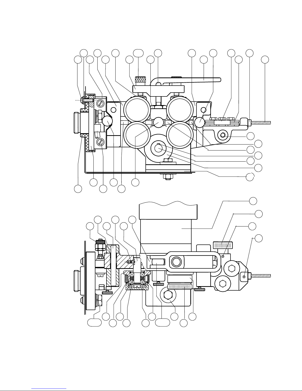
Drahtvorschubgetriebe DV-25
3518

13th1 Spare parts wire feeder model: DV-25
(If spare parts for the wire feeder are needed, always indicate number of the relative
positon and part number)
Pos Description _Part No._
Wire feed gear complete 002.0.2850
with motor and wire feed rollers
1 gear flange (brass part) 002.0.2875
gear flange (complete) 012.0.0287
(Euro connector preassembled)
2 lentil flat-head screw 090.0.0825
3 insulation bush 002.0.2877
4 knurled screw M 4 x 20 090.0.1002
5 bolt (roller) 002.0.2859
6 bolt 002.0.2864
7 rocking bar 002.0.2865
8 cylindrical pin 090.0.0571
9 thread pole M 8 x 90 002.0.2863
10 knurled nut 002.0.2862
11 compression spring 002.0.2690
12 pressure piece 002.0.2861
13 thread case 002.0.2860
14 rocking bar 002.0.2866
15 bullet button 002.0.2856
16 pvc liner 012.0.0377
17 permanent magnet motor 24 VDC 002.0.2630
18 hexagon screw 090.0.4335
washer 090.0.1208
spring ring 090.0.1408
13

Pos Description _Part No._
19 insulation plate 002.0.2876
20 gear insulation 012.0.0285
21 gear angle 002.0.2874
22 sheet steel protection 002.0.2870
23 outgoing nozzle (brass) 6 x 2 x 48 002.0.0367
Outgoing tube (brass) for alu/stainless steel 012.0.0369
6 x 0.6 x 45
24 bolt (roller) 002.0.2873
25 for mild steel/stainless steel:
drive roller with groove V ∅ 0,6 mm 002.0.2879
drive roller with groove V ∅ 0,8 mm 002.0.2880
drive roller with groove V ∅ 1,0 mm 002.0.2881
drive roller with groove V ∅ 1,2 mm 002.0.2882
for aluminium:
drive roller ∅ 0,8 mm alu 002.0.2884
drive roller ∅ 1,0 mm alu 002.0.2885
drive roller ∅ 1,2 mm alu 002.0.2886
drive roller ∅ 1,6 mm alu 002.0.2887
26 knurled screw M 4 x 10 090.0.1001
27 fastener 002.0.2869
28 drive pinion 002.0.2871
29 guidance nozzle (brass) for steel 5 x 1,5 x 40 002.0.2867
guidance nozzle for alu/stainless steel 012.0.0373
(pvc) 5 x 1,5 x 40
30 knurled screw 002.0.2857
31 pressure roller 002.0.2878
32 screw (brass) 025.1.1610
33 incoming nozzle 002.0.2891
34 retaining ring 002.0.2858
39 edge protection rubber (0,3 m) 001.0.0820
14
47
1
3
4
5-
7
8
10
11
14
15
16
17
18
21
22
23
24
26
27
28
29
30
31
45
33
34
37
38
39-
42
43
44
19
20
2
57
32
46
Wire feeder DV-30
12
50
48
49
51
52
57
58
25
63-
.
66
54
15

13th2 Spare parts wire feeder model: DV-30
(If spare parts for the wire feeder are needed, always indicate the number of the relative
positon and part number)
Pos Description _Part No._
Wire feeder block DV-30, without motor, without rollers 012.0.0352
1 Gear box DV-30 012.0.0353
2 left rocking bar 012.0.0276
3 pressure piece 012.0.0261
4 gripping yoke 012.0.0259
5 leveling screw 012.0.0260
6 compression spring 002.0.2688
7 screw 012.0.0266
8 cylindrical pin 090.0.0587
9 compression spring 002.0.2688
10 right rocking bar 012.0.0277
11 eccentric (tentering lever) 012.0.0258
12 knurled screw 090.0.1001
13 hexagonal screw 090.0.4313
14 guide roll 012.0.0239
15 adjusting roll 012.0.0238
16 clamping sleeve 2,5 x 4,5 025.1.1524
17 introductory liner 2,5 x 4,5 002.0.2905
18 sliding block 012.0.0257
19 incoming nozzle for steel 0,8-1,6 (brass) 012.0.0332
19 a incoming nozzle for alu and stainless steel 012.0.0267
0.8-1.6 (pvc)
16

Pos Description _Part No._
20 guidance nozzle for steel 0,8-1,6 (brass) 012.0.0274
20a guidance nozzle for alu and stainless steel 0.8-1.6 (pvc) 012.0.0269
21 feather 090.0.8815
22 DU bush (inside the gear block) 019.1.0121
23 gear (drive pinion) 012.0.0279
24 insulation plate 002.0.0144
25 leveling screw 003.0.1506
26 screw pin 090.0.3303
27 screw pin 090.0.3409
28 DU bush 019.1.0550
29 cylindrical pin 090.0.0598
30 screwpin 090.0.3413
31 bolt 012.0.0268
32 gear pre-assembled 012.0.0278
33 retaining ring 090.0.1814
34 spacing ring 012.0.0235
35 cylinder-head screw 090.0.0937
36 washer 090.0.1205
37 groove ball bearings 019.1.0261
38 feather 090.0.8810
39 eye bolt 090.1.2528
40 compression spring 002.0.2690
41 hexagonal nut 090.0.6055
42 insulation bush 002.0.0200
17

Pos Description _Part No._
43 knurled nut 012.0.0265
44 for mild steel and stainless steel:
drive roller V 1,0 and 1,2 mm ∅(2 pcs. needed) 012.0.0272
pressure roller (2 pcs. needed) 012.0.0271
drive roller V 0,8 and 1,6 mm ∅ (2 pcs. needed) 012.0.0273
pressure roller (2 pcs. needed) 012.0.0271
for aluminium:
drive roller U 1,0 and 1,2 mm ∅ (2 pcs. needed) 012.0.0281
pressure roller (2 pcs. needed) 012.0.0271
drive roller U 0,8 and 1,6 mm ∅ (2 pcs. needed) 012.0.0282
pressure roller (2 pcs. needed) 012.0.0271
for cored wire:
drive roller for cored wire 1,2 and 1,6 mm ∅ (2 pcs. needed) 012.0.0291
pressure roller (2 pcs. needed) 012.0.0271
drive roller for cored wire 2,0 and 2,4 mm ∅ (4 pcs. needed) 012.0.0292
drive roller for cored wire 2,8 and 3,2 mm ∅ (4 pcs. needed) 012.0.0293
45 O ring 013.8.0010
46 sliding block 012.0.0254
47 outgoing nozzle for steel 0,8-1,6 mm ∅ (brass) 012.0.0333
outgoing nozzle for cored wire 1,6-2,4 mm ∅ (brass) 012.0.0335
outgoing nozzle for aluminium 0,8-1,6 mm ∅ (pvc) 102.998
48 lentil flat-head screw 090.1.0825
49 insulation bush 002.0.2877
50 gear insulation 012.0.0285
51 insulating plate 002.0.2876
52 gear flange complete (euro connector) 012.0.0287
53 cylinder-head screw 090.0.0931
54 insulating bush 002.0.2877
55 washer 090.0.1204
56 self-locking screw nut 090.0.6053
18

Pos Description _Part No._
57 knurled screw 090.0.1002
58 screw nut (for gas) 002.0.2896
59 hexagonal screw 090.0.4328
60 washer 090.0.1207
61 spring ring 090.0.1407
62 screw nut 090.0.5008
63 hexagonal screw 090.0.4335
64 washer 090.0.1208
65 spring ring 090.0.1408
66 motor 42 VDC (DV-30) with tacho 002.0.2512
19

Front panel
5
HOLD
0
0.5
0.75
1.0
1.25
1.5
1.75
2.0 sec.
Drahtvorschub
Drahtvorschubgerät
Rückbrand
0.5
0.75
1.0
1.25
1.5
1.75
1
2
4-Takt/latch
2-Takt/2 steps
Intervall/stitch
Punkten/spot welding
external wire feeder
Pause
intermission
wire feed
wire burn back
Schweißzeit
timer
2.0 sec.
0,8
1,0
1,2
4
Hauptschalter/Grobstufe
main switch/coarse selector
2
1
1
1
2
2
7
1
2
3
4
Feinstufe
fine selector
2
5
6
8 9
10
11
12
13
14
3
Drahtvorschub
wire feed
[m/min]
1
5
10
15
20
5
25
1
10
15
20
25
30
DV-25
DV-30
17
16
15
E 2864-33E 2864-33
20

14th Operation of the Unit:
Front panel:
Pos. 1 Step selector/fine selector 7 steps
Pos. 2 Selector range 1/2 (M 301 )
Coars selector 4 steps (M 351), 6 steps (M 451/ M 551)
Pos. 3 Control lamp, unit is switched on
Pos. 4 potentiometer, intermission timer for stitch mode
Pos. 5 potentiometer, welding timer for stitch mode and spot welding
Pos. 6 LED (yellow) temperature protection
Pos. 7 LED (red) failure (only KW/DW version)
Pos. 8 Selector operation mode
Pos. 9 potentiometer, wire feed speed
Pos.10 Switch 'wire feed control'
With this switch the wire feed speed can either be adjusted at the machine
(potentiometer Pos. 9) or at the separate wire feeder unit (potentiometer Pos.
16, only models D/DW). When working with a compact machine (model
K/KW) this switch must be in position 'remote control off'
Pos.11 potentiometer, wire burn back
Pos.12 LED (green) hold (option)
Pos.13 Display wire feed speed m/min (option)
Pos.14 Display welding current A (option)
Pos.15 Socket, push pull or remote control (option)
Pos.16 potentiometer, wire feed speed at the separate wire feeder (only D/DW)
Pos.17 Switch, remote control wire feed (option)
2-stroke operation:
as long as the torch switch is pressed down, the welding current is on
4-stroke operation:
1 st stroke: torch switch pressed -welding on 2nd stroke: torch switch released
3rd stroke: torch switch pressed -welding off 4th stroke: torch switch released.
Stitch (interval) operation:
Welding current and wire feeder are switched on and off automatically. The welding time and
the intermission time can be controlled by the var. resistors Pos. 4 and Pos. 5.
Spot welding:
The spot welding time is can be adjusted by the var. resistor Pos. 5.
IMPORTANT: When operating a model 'W' with integrated water cooling system,
always check the filling of the water tank. When the machine is
stored or operated at temperatures below 0°C use 'MERKLE
coolant MKF' instead of water (part-no.: 107.822)
21

15th Ein adjust worth
15th1 Voltage settings: M 301 K/D for mild steel
Range m/min. current (A) m/min. Current (A) m/min. current (A)
(fine /
coars)
wire 0,8 wire 1,0 wire 1,2
1 - 1 1,9 30 1,7 40
1 - 2 2,3 45 2,0 50
1 - 3 2,7 50 2,4 60 2,2 80
1 - 4 3,1 60 2,8 75 2,7 95
1 - 5 4,4 75 3,4 85 3,0 110
1 - 6 5,4 95 4,1 100 3,3 125
1 - 7 6,8 105 4,6 115 3,6 140
2 - 1 7,7 123 4,9 130 3,9 155
2 - 2 10,8
140
6,1 150 4,7 175
2 - 3 13,0 160 8,8 180 5,9 200
2 - 4 15,3 180 11,2 210 7,7 230
2 - 5 17,9 200 13,4 240 9,5 250
2 - 6 21,7 225 15,4 260 10,8 275
2 - 7 25,3 258 18,3 286 11,7 305
22

15th2 Voltage setting: M 351 K/D/KW/DW for mild steel
Range m/min. current (A) m/min. current (A) m/min. current (A)
(fine - coars) wire 0,8 wire 1,0 wire 1,2
1 - 1 2,3 40 1,7 50
1 - 2 2,5 45 1,8 53
1 - 3 2,8 50 2,0 57
1 - 4 3,2 60 2,2 60 2,0 80
1 - 5 3,5 65 2,6 63 2,2 90
1 - 6 3,8 70 2,6 67 2,3 100
1 - 7 3,9 2,7 70 2,4 110
2 - 1 4,0 80 2,8 75 2,6 120
2 - 2 4,5 85 3,1 80 2,8 123
2 - 3 5,0 90 3,4 90 3,0 127
2 - 4 5,5 90 3,7 100 3,2 130
2 - 5 5,7 95 3,9 105 3,3 135
2 - 6 6,0 100 4,0 110 3,4 140
2 - 7 6,8 110 4,1 120 3,5 145
3 - 1 7,6 120 4,8 130 3,8 150
3 - 2 8,2 125 5,2 140 4,3 160
3 - 3 9,0 132 5,8 150 4,8 170
3 - 4 9,8 140 6,4 165 5,5 190
3 - 5
11,0 150 7,0 172 5,9 200
3 - 6 13,0 160 8,0 180 6,3 215
3 - 7 14,3 170 9,0 190 6,8 230
4 - 1 15,8 180 10,2 210 7,6 245
4 - 2 17,9 190 11,6 220 8,1 255
4 - 3 19,0 200 13,3 230 8,8 270
4 - 4 20,5 215 14,3 240 9,4 284
4 - 5 22,8 230 15,2 255 9,9 295
4 - 6 24,5 250 16,1 270 10,6 310
4 - 7 25,0 260 17,7 280 11,3 328
23

15th3 Voltage setting: M 451 KW / DW for mild steel
Range m/min. current (A) m/min. current (A) m/min. current (A)
(fine - coars) wire 0,8 wire 1,0 wire 1,2
1 - 1 1,8 30 1,7 45
1 - 2 1,8 35 1,7 50
1 - 3 1,9 35 1,8 55
1 - 4 2,0 40 1,8 57
1 - 5 2,1 40 1,8 60
1 - 6 2,3 50 1,9 65
1 - 7 2,4 50 2,0 70
2 - 1 2,8 55 2,4 75 1,6 100
2 - 2 3,2 60 2,6 80 1,8 110
2 - 3 3,6 62 2,9 89 1,9 120
2 - 4 3,8 65 3,1 93 2,1 125
2 - 5 4,0 70 3,3 100 2,4 132
2 - 6 4,2 80 3,5 110 2,4 136
2 - 7 4,5 90 3,7 120 2,6 140
3 - 1 5,2 95 3,8 100 2,6 142
3 - 2 5,2 100 4,0 125 2,7 145
3 - 3 5,4 103 4,2 126 3,2 150
3 - 4 5,6 105 4,4 130 3,2 161
3 - 5 5,9 110 4,6 130 3,4 165
3 - 6 6,3 120 4,7 136 3,5 171
3 - 7 7,4 125 4,8 141 3,6 175
4 - 1 8,2 130 5,2 145 4,3 180
4 - 2 8,7 130 5,8 150 4,8 190
4 - 3 9,6 140 6,4 160 5,0 205
4 - 4 10,0 145 7,0 170 5,3 211
4 - 5 10,4 153 7,8 180 5,5 215
4 - 6 11,0 160 8,6 195 5,7 220
4 - 7 12,5 162 9,6 205 6,0 225
5 - 1 13,8 170 10,2 210 7,3 240
5 - 2 14,8 175 11,3 220 7,9 250
5 - 3 15,2 180 12,5 230 8,2 255
5 - 4 15,5 190 13,3 240 8,5 265
5 - 5 16,0 195 14,2 250 9,0 277
5 - 6 17,0 200 15,2 255 9,5 285
5 - 7 18,1 210 16,4 265 10,2 290
6 - 1 20,3 220 18,4 275 11,6 300
6 - 2 22,5 230 20,0 285 13,0 330
6 - 3 25,1 250 21,2 300 14,4 360
6 - 4 29,5 270 22,7 320 15,8 370
6 - 5 25,1 350 17,2 390
6 - 6 27,5 370 18,2 410
6 - 7 30,0 400 425 425
24

15th4 Voltage setting: M 551 DW for mild steel
Range m/min. current (A) m/min. current (A) m/min. current (A)
(fine / coars) wire 0,8 wire 1,0 wire 1,2
1 - 1 2,6 45 2,2 55
1 - 2 2,7 47 2,3 60
1 - 3 2,9 50 2,4 65
1 - 4 3,3 55 2,5 70
1 - 5 3,7 65 2,6 72
1 - 6 4,2 75 2,8 75
1 - 7 4,8 80 2,9 79
2 - 1 5,4 85 3,0 80 2,0 100
2 - 2 5,6 90 3,1 90 2,2 108
2 - 3 5,8 95 3,5 110 2,4 115
2 - 4 6,0 102 3,7 110 2,7 120
2 - 5 6,5 107 4,0 120 2,9 125
2 - 6 7,3 115 4,3 131 3,2 135
2 - 7 7,7 120 4,5 135 3,5 140
3 - 1 8,0 125 4,6 145 3,7 150
3 - 2 8,4 130 4,8 150 3,9 165
3 - 3 9,0 137 5,7 158 4,1 175
3 - 4 9,6 140 6,4 165 4,5 186
3 - 5 10,1 145 6,8 175 4,8 190
3 - 6 11,7 150 7,2 180 5,0 200
3 - 7 13,0 164 8,3 185 5,6 210
4 - 1 13,4 170 8,7 190 5,9 215
4 - 2 13,6 175 9,1 195 6,1 220
4 - 3 13,8 182 9,6 200 6,7 225
4 - 4 14,0 190 10,4 210 7,2 235
4 - 5 15,1 195 11,8 215 7,7 245
4 - 6 16,6 200 13,0 225 8,5 255
4 - 7 17,6 205 13,9 235 9,4 270
5 - 1 20,0 210 14,4 240 10,3 285
5 - 2 20,9 215 14,9 250 10,9 290
5 - 3 22,3 220 15,5 260 11,5 300
5 - 4 23,0 225 16,3 275 12,0 312
5 - 5 25,0 235 17,1 280 12,5 325
5 - 6 27,5 250 18,1 295 13,1 340
5 - 7 30,0 260 19,4 310 14,6 360
6 - 1 21,3 330 15,7 375
6 - 2 23,1 340 16,4 400
6 - 3 25,0 350 17,2 410
6 - 4 28,7 365 17,9 435
6 - 5 30,0 380 19,4 450
6 - 6 22,1 465
6 - 7 27,0 480
25

16th Trouble Shooting
16th1 Machine does not operate after switching on the main switch
a) Check main supply
b) Check main fuses
16th2 Machine does not react on the torch switch
a) Problem at the torch switch
b) Check internal fuses
16th3 Control LED (red) is on
a) Thermical protection switch for water pump is activated
b) Fuse is blown
16th4 Water pump is running, control LED (red) is on
a) Water pressure too low, check water level
b) Water pressure switch is not ok
16th5 Control LEDs (yellow) and (red) are on
a) Over temperature at transformer or rectifier. Wait for cooling down of the unit
16th6 Machine has no or too low welding current
a) Main contactor relays is not working
b) Bad or no contact at the earth lead
c) Torch hose completely or partially broken
d) Problem with rectifier in the machine
e) Only 2 main phases are connected, check main fuses
16th7 Welding quality is poor
a) No or not enough gas flow
b) Air is mixed into the protective gas. Open gas valve and close it again. Gas pressure must
remain in the gas hose. Check at the regulator.
c) Gas nozzle or tip holder are covered with spatters. Gas flow is not o.k.
d) Tip holder is not fixed properly. Air is mixed into the protective gas via the wire
e) Extremely oxidated work piece.
f) Air is coming to the welding area because of wind.
16th8 Problems with wire feeding and wire contacting
a) The hole in the contact tip has wrong diameter or contact tip must be changed.
b) Wire core is extremely dirty.
c) Kinks in the wire core.
d) Wrong diameter of the wire core.
e) Pressure at drive rollers is to low.
f) Wrong or old drive rollers.
g) Welding wire is not running in the axis of the drive rollers.
h) Mechanical resistance of the welding wire is too high.
16th9 Burning of the liner
a) Electrical connection between wire feed gear and welding current. Check wire
feeder for pieces of welding wire in the gear .
b) Check power cable or flange nut in the Euro-connector for a good connection.
26

17th Spare part list and wiring diagram
17th1 Spare part list M 301 K/D
electr. description part no.
-A0 pc board ME-EMV-1.3 (supply voltage filter) 00300070
-A1 pc board ME-MAG-5.1C 00300514
-A2 pc board ME-MAG-5.1 DIS (option digital display) 00300516
-A3 pc board ME-PPMR-2.1 00300493
(option push pull and remote control)
-A4 pc board ME-PPMR/AN-2.0 00300485
(option push pull and remote control)
-A5 LEM converter HTA 400-5 (option digital display) 01001615
-F1 fuse 4 A, slow 6,3x32 00301251
-F2 fuse 4 A, slow 6,3x32 00301251
-F3 fuse 10 A slow 5x20 00301199
-F5 temperature switch 112 °C opening 00100408
-F6 temperature switch 80°C opening 00100406
-H1 control lamp 230 V 00301238
lamp holder green 00301239
-K1 contactor A 12-30-10 42V 50/60 Hz 00100302
-L1 choke M 301 107040
-M1 wire feed motor 00202630
-M2 fan 230V 00101323
-M3 fan 230V 00101323
-Q1 switch WAM 271/10ZM/Z6 00100078
-Q2 switch WAM 276/10ZM/Z11/Z6 00100079
-R1 resistor 0,33 ohm 50 watt 03008612
-R2 potentiometer 10 kohm 00100502
-S1 switch 2-pol 00300900
-S2 switch 2-polig (option automated welding) 00300900
-T1 main transformer ME 301 3x400V 104590
-T2 control transformer El 96/59,7 100550
-T3 current converter (green) 02011124
-V1 rectifier 320 A 00100198
27

electr. description part no.
-X1 Euro connector 01200287
-X2 connector 1,5/2,5, 5 pol. 01700617
-X3 male connector 24 pol. 01500501
-X3 female connector 24 pol 01500500
-X4 male connector 24 pol
01500500
-X4 female connector 24 pol 01500501
-X5 connector 1,5/2,5, 5 pol. 01700617
-X6 socket 10-pol. 02110386
(option push pull and remote control)
-X7 male connector 6-pol. (option automated welding) 01500102
-X9 socket 35/50 mm² 00101101
-X10 socket 35/50 mm² 00101101
-X12 plug DIX SE 50/70 01201508
-X12 socket 35/50 mm² 00101101
-Y1 gas valve 42V/AC 00201602
-Z2 protection device 00300327
-Z3 protection device 00300330
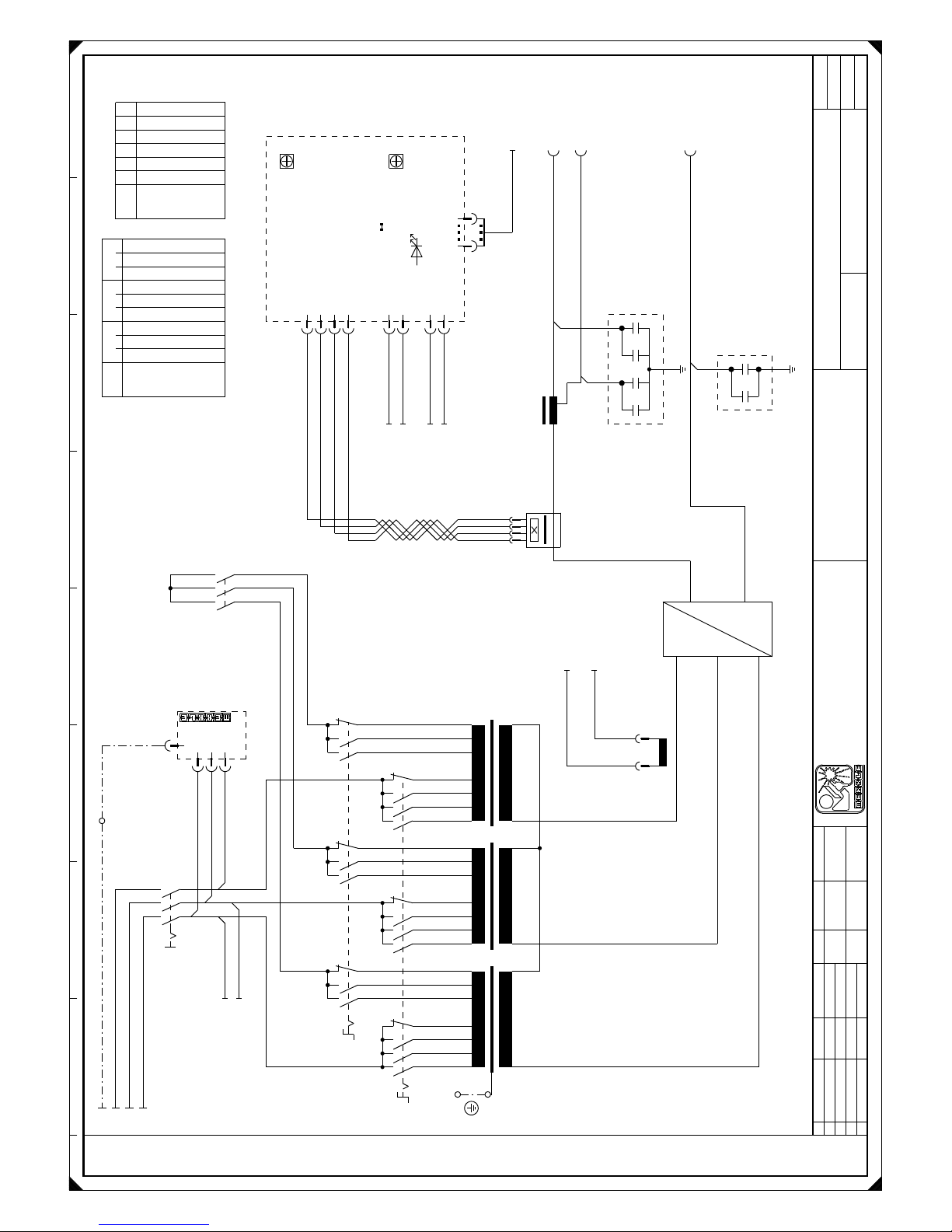
17.2 Wiring diagramm M 301 K/D
28

1 2 3 4 5 6 7 8
-K1
1
2
3
4
5
6
-Q1
15 13 11 7 9 5
14/16
8/12 6/10
0
1 2
+OP1
-A5
Option:
Digitalanzeige
display
2 3 41
-T3
-X9
-
60%
-A0
ME-EMV-1.3ME-EMV-1.3
L1L2L3
PE
-T1
1-sw
2-sw
6-sw
7-sw
8-sw
1-bl
2-bl
6-bl
8-bl
7-bl
1-br
2-br
6-br
7-br
8-br
~
~
~
PE
Schwarz
Blau
Braun
-Q1
2
4
1
3
-M3
PE
M
-M2
PE
M
-X5
1
1
2
2
3
3
4
4
5
5
-X10
-
100%
-Z3
-Q2
135
7911
131517
Stufe 1-7
T2
S2
R2
-V1
~
~
~
+
-
~
=
-Z2
-X1
+
-L1
L1
L2
L3
PE
+SQ-A1-X2:9/2.4
+SQ-A1-X2:10/2.4
+OP1
-A2
P1
NO
Hold
Draht
wire
Strom
current
P1
P2
ME-MAG-5.1/DIS
X2
rot
I>0
X3
X4
1
2
1
2
1
2
3
4
1 10
X1
+SQ-T2:0V/2.2
+SQ-T2:400V/2.2
+SQ-A1-X1:1/2.7
+SQ-T2:0/230V/2.2
Erdungs-
schraube
Erdungs-
schraube
Erdungs-
schraube
+OP1-A1-X4/2.5
+SQ-T2:w10-0V/2.2
+SQ-T2:w10-9V/2.2
+OP2-X7:2/2.4
+OP2-X7:1/2.4
432
1
2
1
2
1
4321
sw
sw
sw
sw sw
bn
gr
sw-ws
sw-rt
sw
br
sw
ws
ws-sw
ws-bl
gn
gr
ws
sw
sw
sw
sw
/2.2
.2
.2
1234567
1 2 3
T1/R
XXX
XXX
X
1 2 3
T1/S
X
XXX
XXX
1 2 3
T1/T
X
X
XXX
X
X
Q2
Brenner
torch
Werkstück
work piece
Lüfter
fan
Option:
Digitalanzeige
display
Flachbandkabel
flat band cable
3PH-400V/50-60Hz/PE
Blatt
2
Bl.
1
Projektbez.
Auftragsnr.
Zeichnungsnr.
M301K
Änderung
Datum
gez.
gepr.
Name
Datum
Name
Konrad
04.04.02
Siegner
10.04.02
Schweißstromkreis
Vervielfältigung oder Weitergabe nur mit unserer schriftlichen Genehmigung gestattet
c
dab
Plotdatum:
20.05.03
Merkle
Schweißanlagen-Technik GmbH
Industriestraße 3
D - 89359 Kötz
Telefon 08221 -915 - 0
Telefax 08221 - 32596
=
+
SQ

1 2 3 4 5 6 7 8
-R1
-Y1
-X2
7 7
8 8
16 16
17 17
18 18
-T2
400V0V230V
0/230V
W2-9V
W2-0V
W4-18V
W4-0V
W5-9V
W5-0V
W3-0V
W3-42V
W3-26V
PE
-H1
-F1
4At
-F2
4At
-F3
10At
+SQ-A2-X4:1/1.5
+SQ-A2-X4:2/1.5
-K1
A1
A2
+SQ-T2:w2-9V/2.2
+SQ-F5/2.2
+SQ-T2:230V/2.2
+SQ-X5:3/1.7
+SQ-Q1:3/1.2
+SQ-X5:2/1.7
+SQ-A1-X1:6/2.7
+SQ-A1-X1:3/2.7
+SQ-Q1:1/1.2
-F5
Trafo-Pr.
-A1
ME-MAG-5.1C
ge
Störung
failure
rt
T>
min P5
max P6
213
4
X3
5 12346789101112
X2
1 2
X6
X4
21345
6
X1
X5
4
3
2
1
JP2
HI
T-OFF
Lüfter/fan
Brennert.
torch switch
Wasser
water
Lüfter ein/fan on
Lüfternachlaufzeit/fan after-run time
Lüfterumschaltung/fan switching
ZÜNDV
soft start
JP1
ZV
ein/on
aus/off
+OP1-A2-X1/1.6
-F6
Gleichrichter
rectifer
-X2
1
1
2
2
5
5
3
3
4
4
-X1
A B
-M1
+
-
M
=
+OP6
-A6
+
-
2 13
X2
X3
10 1
10 1
Display
MAG
Uist
X4
X1
ME-MAG-5/ZW3
+OP6
-S3
1
2
3
+SQ-V1:+/1.4
+SQ-V1:-/1.4
+OP1-A1-X4/2.5
+OP1-A2-X1/1.6
+SQ-A1-X1:5/2.7
Erdungs-
schraube
432
1
21
4
3
2
1
6
5
4
3
2
1
12 11 10
9 8 7 6 5 4 3 2 1
+OP2
-S2
1
2
3
Hand/Automatik
hand/automatic
+OP2
-X7
1
2
3
4
5
6
+SQ-T3/1.3
+SQ-T3/1.3
+OP1-A2-X2:1/1.5
+OP1-A2-X2:2/1.5
+SQ-X2:3/2.5
+SQ-X2:4/2.5
+SQ-A1-X2:3/2.4
+SQ-F6/2.5
-X1
PIN-NR.
STROMPFAD
1
2
3
bn-ws
bn-gn
bn-sw
bl-ws
vio-ws
or-ws
bl-gn
bl-ws
bl-sw
bl-gn
bl-sw
gn
ge
or
bn
gn-sw
ws
vio
bl
rt
ge ge
or
rs
vio
ws
bn
bn-ws
sw-rt
sw-ws
rs
bn-gn
bl-sw
bn-sw
bl-ws bl-ws
vio
vio-sw
vio-ge
bl-gn
26
25
bl-gn
bl-ws
sw
bn
vio-ge
bn-sw
vio-sw
bn-gn
bn-ws
ws-bl
ws-sw
or-sw
sw
gr
bl-rt
ws
sw
bl-ws
.5
.2
1 2
3 4
/1.1
/1.1
/1.1
5 6
13 14
/1.7
.5
.5
BT.
Flachbandkabel
flat band cable
Spannung
Draht
Option:
Anzeige umschaltbar
Volt oder m/min
Flachbandkabel
flat band cable
Blatt
2
Bl.
2
Projektbez.
Auftragsnr.
Zeichnungsnr.
M301K
Änderung
Datum
gez.
gepr.
Name
Datum
Name
Konrad
04.04.02
Siegner
10.04.02
Steuerstromkreis
Vervielfältigung oder Weitergabe nur mit unserer schriftlichen Genehmigung gestattet
c
dab
Plotdatum:
20.05.03
Merkle
Schweißanlagen-Technik GmbH
Industriestraße 3
D - 89359 Kötz
Telefon 08221 -915 - 0
Telefax 08221 - 32596
=
+
SQ

1 2 3 4 5 6 7 8
-K1
1
2
3
4
5
6
-Q1
15 13 11 7 9 5
14/16
8/12 6/10
0
1 2
+OP1
-A5
Option:
Digitalanzeige
display
2 3 41
-T3
-A0
ME-EMV-1.3ME-EMV-1.3
L1L2L3
PE
-T1
1-sw
2-sw
6-sw
7-sw
8-sw
1-bl
2-bl
6-bl
8-bl
7-bl
1-br
2-br
6-br
7-br
8-br
~
~
~
PE
Schwarz
Blau
Braun
-Q1
2
4
1
3
-M3
PE
M
-M2
PE
M
-X5
1
1
2
2
3
3
4
4
5
5
-Z3
-Q2
135
7911
131517
Stufe 1-7
T2
S2
R2
-V1
~
~
~
+
-
~
=
-Z2
-X10
-
100%
-X9
-
60%
-X12
-L1
L1
L2
L3
PE
+SQ-A1-X2:9/2.4
+SQ-A1-X2:10/2.4
+OP1
-A2
P1
NO
Hold
Draht
wire
Strom
current
P1
P2
ME-MAG-5.1/DIS
X2
rot
I>0
X3
X4
1
2
1
2
1
2
3
4
1 10
X1
+SQ-T2:0/230V/2.2
+SQ-A1-X1:1/2.7
+SQ-T2:400V/2.2
+SQ-T2:0V/2.2
Erdungs-
schraube
Erdungs-
schraube
Erdungs-
schraube
+OP1-A1-X4/2.5
4321
+SQ-T2:w10-0V/2.2
+SQ-T2:w10-9V/2.2
+OP2-X7:2/2.8
+OP2-X7:1/2.8
2
1
2
1
432
1
sw
sw
sw sw
br
gr
sw-ws
sw-rt
sw
br
sw
ws
ws-sw
ws-bl
gn
gr
ws
sw
sw
sw
sw
/2.2
.2
.2
1234567
1 2 3
T1/R
XXX
XXX
X
1 2 3
T1/S
X
XXX
XXX
1 2 3
T1/T
X
X
XXX
X
X
Q2
3PH-400V/50-60Hz/PE
+
Werkstück
work piece
Lüfter
fan
Option:
Digitalanzeige
display
Flachbandkabel
flat band cable
Blatt
4
Bl.
1
Projektbez.
Auftragsnr.
Zeichnungsnr.
M301D
Änderung
Datum
gez.
gepr.
Name
Datum
Name
Konrad
04.04.02
Siegner
10.04.02
Schweißstromkreis
Vervielfältigung oder Weitergabe nur mit unserer schriftlichen Genehmigung gestattet
c
dab
Plotdatum:
20.05.03
Merkle
Schweißanlagen-Technik GmbH
Industriestraße 3
D - 89359 Kötz
Telefon 08221 -915 - 0
Telefax 08221 - 32596
=
+
SQ

1 2 3 4 5 6 7 8
-R1
-F6
Gleichrichter
rectifer
-T2
400V0V230V
0/230V
W2-9V
W2-0V
W4-18V
W4-0V
W5-9V
W5-0V
W3-0V
W3-42V
W3-26V
PE
-H1
-F1
4At
-F2
4At
-F3
10At
+SQ-T2:w2-9V/2.2
+SQ-F5/2.2
+SQ-T2:230V/2.2
+SQ-X5:3/1.7
-F5
Trafo-Pr.
+SQ-Q1:3/1.2
+SQ-A1-X1:6/2.7
+SQ-X5:2/1.7
+SQ-A1-X1:3/2.7
+SQ-Q1:1/1.2
-A1
ME-MAG-5.1C
ge
Störung
failure
rt
T>
min P5
max P6
213
4
X3
5 12346789101112
X2
1 2
X6
X4
21345
6
X1
X5
4
3
2
1
JP2
HI
T-OFF
Lüfter/fan
Brennert.
torch switch
Wasser
water
Lüfter ein/fan on
Lüfternachlaufzeit/fan after-run time
Lüfterumschaltung/fan switching
ZÜNDV
soft start
JP1
ZV
ein/on
aus/off
Erdungs-
schraube
-X2
1
1
2
2
5
5
3
3
4
4
-X3
10 9 12
+OP2
-S2
1
2
3
Hand/Automatik
hand/automatic
+OP1-A2-X2:1/1.5
+OP1-A2-X2:2/1.5
+SQ-X2:3/2.5
+SQ-X2:4/2.5
+SQ-A1-X2:3/2.4
+SQ-F6/2.6
+SQ-T3/1.3
+SQ-T3/1.3
-X2
7 7
8 8
16 16
17 17
18 18
-K1
A1
A2
+OP3-A3-X2:3/3.6
+OP3-A3-X2:4/3.6
18
17
16
8
7
23
-X3
24
+SQ-A2-X4:1/1.5
+SQ-A2-X4:2/1.5
21
432
1
6
5
4
3
2
1
4
3
2
1
12 11 10
9 8 7 6 5 4 3 2 1
+SQ-A1-X1:5/2.7
+OP2
-X7
1
2
3
4
5
6
+OP1-A2-X1/1.6
vio-ws
or-ws
bl-ws
or or
gn
ge ge
vio-ge
vio-sw
gn-sw
ws-rt
ws-br
ge
or
bn-ws bn-ws
rs
vio
bn-gn bn-gn
ws
br
bn-sw bn-sw
bl-ws bl-ws bl-ws
vio-sw
bl-gn
vio-ge
rs
sw-rt
sw-ws
bl-sw
vio
or-sw
vio-ws
bl-ws
sw
br
vio-ge
bn-sw
vio-sw
bn-gn
bn-ws
ws-bl
or-sw
ws-sw
sw
gr
bl-rt
ws
bl-sw
sw
bl-ws
.2
.5
1 2
3 4
/1.1
/1.1
/1.1
5 6
13 14
Flachbandkabel
flat band cable
Blatt
4
Bl.
2
Projektbez.
Auftragsnr.
Zeichnungsnr.
M301D
Änderung
Datum
gez.
gepr.
Name
Datum
Name
Konrad
04.04.02
Siegner
10.04.02
Steuerstromkreis
Vervielfältigung oder Weitergabe nur mit unserer schriftlichen Genehmigung gestattet
c
dab
Plotdatum:
20.05.03
Merkle
Schweißanlagen-Technik GmbH
Industriestraße 3
D - 89359 Kötz
Telefon 08221 -915 - 0
Telefax 08221 - 32596
=
+
SQ

1 2 3 4 5 6 7 8
-X4
12
-M1
+
-
M
=
-R2
E
A
S
-Y1
3456789101112131415161718192021222324
1234567891011121314151617181920212223
+VB
-X4
24
+VB
-X3
1234567891011121314151718192021222324 16
A
Option:
PP-Brenner oder
Fernregleranschluß
pp-torch or
remote control
A
-X1
B
+
-
M
=
E
A
S
H
+VB
-X12
-X13
1
-X1
+
D
C
J
K
+OP3
-A3
rt
Freigabe/
enable
X4
ME-PPMR-2.1
X1
1
2
3
4
5
6
7
8
X2
1
2
3
4
5
6
1 10
X3
JP1
JP2
>3m
1A-träge/
slow
+OP3
-X6
B
+OP6
-S3
1
2
3
+OP3
-S1
4
5
6
65432
1
+SQ-T2:w3-0V/2.2
+SQ-T2:w3-42V/2.2
+SQ-X3:24/2.4
+SQ-X3:23/2.4
+SQ-X2:1/2.5
+SQ-X2:2/2.5
+OP1-A2-X1/1.6
+OP1-A1-X4/2.5
+SQ-V1:+/1.4
+SQ-V1:-/1.4
+OP6
-A6
+
-
2 13
X2
X3
10 1
10 1
Display
MAG
Uist
X4
X1
ME-MAG-5/ZW3
+OP3
-A4
ME-PPMR/AN 2.0
rt
+
rt
gn
0
-
110
X1
vio
bl
rt
bn
ws
vio-ge
vio-sw
ws-bn
ws-rt
gn-sw
gn-ws
gn
rt
DV-Gerät
wire feeder
BT.
PP-Motor
D
C
JKA
B
H
BT.
VB-Kabel
Drahtvorschub
wire feed
Brenner
torch
DV-25
Flachbandkabel
flat band cable
Draht
Spannung
Option:
Anzeige umschaltbar
Volt oder m/min
Flachbandkabel
flat band cable
Blatt
4
Bl.
3
Projektbez.
Auftragsnr.
Zeichnungsnr.
M301D
Änderung
Datum
gez.
gepr.
Name
Datum
Name
Konrad
04.04.02
Siegner
10.04.02
DV-Kasten
Vervielfältigung oder Weitergabe nur mit unserer schriftlichen Genehmigung gestattet
c
dab
Plotdatum:
20.05.03
Merkle
Schweißanlagen-Technik GmbH
Industriestraße 3
D - 89359 Kötz
Telefon 08221 -915 - 0
Telefax 08221 - 32596
=
+
DV

17th3 Spare part list M 351 K/D/KW/DW
electr. description part no.
-A0 pc board ME-EMV-1.3 (supply voltage filter) 00300070
-A1 pc board ME-MAG-5.1C 00300514
-A2 pc board ME-MAG-5.1 DI5 (option digital display) 00300516
-A3 pc board ME-PPMR-2.1 00300493
(option push pull and remote control)
-A4 pc board ME-PPMR/AN-2.0 00300485
(option push pull and remote control)
-A5 LEM converter HTA 400-5 (option digital display) 01001615
-C1 capacitor 6 uF, 420V/AC 00100425
-F1 fuse 4 A, slow 6,3x32 00301251
-F2 fuse 4 A, slow 6,3x32 00301251
-F3 fuse 10 A slow, 5x20 00301199
-F4 fuse 1 A 5x20 00301212
-F5 temperature switch 112 oC opening 00100408
-F6 temperature switch 80°C opening 00100406
-F7 temperature switch 40°C closing 00100345
-F8 water pressure switch 0,5 bar 00400204
-F9 bar thermical current protector 1 ,4 A 00300320
-H1 control lamp 230 V 00301238
lamp holder green 00301239
-K1 contactor A 16-30-10 42V 50/60 Hz 00100311
-L1 choke M 351 00101676
-M1 wire feed motor 24V-DC (DV 25) 00202630
-M2 fan 230V 00101301
-M3 water pump 230V 50Hz 00400530
-M4 wire feed motor 42V-DC (option DV-30) 00202512
-Q1 switch HLT 40/3ZM/X99/NR
00100014
-Q2 switch ST 63/32E 00100108
-Q3 switch WAM 227/32E/Z11/X97 00100098
-R1 resistor 0,33 ohm 50 watt 03008612
-R2 potentiometer 10 kohm 00100502
-S1 switch 2-polig 00300900
-S2 switch 2-polig (option automated welding) 00300900
34

electr. description part no.
-T1 main transformer M 351 00101675
-T2 control transformer El120/73,7 950VA 00300242
-T3 current converter (green) 02011124
-V1 rectifier 320 A 00100198
-X1 Euro connector 01200287
-X2 connector 1,5/2,5, 5 pol. 01700617
-X3 female connector 24 pol. 01500501
-X3 male connector 24 pol. 01500500
-X4 male connector 24 pol. 01500500
-X4 female connector 24 pol. 01500501
-X5 connector 1,5/2,5, 5 pol. 01700617
-X6 socket 10-pol. 02110386
( option push pull and remote control)
-X7 male connector 6-pol. (option automated welding) 01500102
-X9 socket 35/50 mm2 00101101
-X10 socket 35/50 mm2 00101101
-X12 socket 70/95mm2 500A 00101102
-X12 plug DIX SE 50/70 01201508
-Y1 gas valve 42V/AC 00201602
-Z2 protection device 00300327
-Z3 protection device 00300330
17.4 Wiring diagramm M 351 K/D/KW/DW
35
1 2 3 4 5 6 7 8
-A0
ME-EMV-1.3ME-EMV-1.3
L1L2L3
PE
-Q1
L1 L2 L3
T1 T2 T3
-X11
PE
-V1
~
~
~
-
+
~
=
-L1
100%
66%
-Z2
123
4
+OP1
-A5
2 3 41
2
112
-X11
PE
-T1
U1
U2
U3
U4
R1
R2
R3
V1
V2
V3
V4
S1
S2
S3
W1
W2
W3
W4
T1
T2
T3
~ ~ ~
PE
-Q2
1 2 3 4 1 2 3 4 1 2 3 4
L1
L2 L3
-Q3
S2
T2
1 3 5 7 9 11 13 15 17
R2
2 4 6 8 10 12 14 16 18
-T3
1
-X8
2
-Z3
L1
L2
L3
PE
+SQ-T2:-0V/2.2
+SQ-T2:9V/2.2
+OP2-X7:2/2.6
+OP2-X7:1/2.6
-X1
+
-X10
-X9
+OP1
-A2
P1
NO
Hold
Draht
wire
Strom
current
P1
P2
ME-MAG-5.1/DIS
X2
rot
I>0
X3
X4
1
2
1
2
1
2
3
4
1 10
X1
1 2 3 4
-K1
2
1
4
3
6
5
+SQ-T2:w1-400V/2.2
+SQ-T2:w1-0V/2.2
+SQ-A1-X2:9/2.5
+SQ-A1-X2:10/2.4
+OP1-A1-X4/2.5
sw
sw-ws
sw-rt
br
ws
ws-sw
ws-bl
gn
gr
ws
sw
sw
sw
sw sw
sw
sw sw
sw
sw
/2.2
3PH-400V/50-60Hz/PE
Q3
7 8 9 7 8 9 7 8 9
1234567
U
V
W
xxx
xxx
x
x
xxx
xxx
x
x
xxx
x
x
Q2
12345
6
1 2 3 4 5 6
x
x
x
x
x
x
Option:
Digitalanzeige
display
-
-
Option:
Digitalanzeige
display
Werkstück
work piece
Brenner
torch
Blatt
3
Bl.
1
Projektbez.
Auftragsnr.
Zeichnungsnr.
M351K
Änderung
Datum
gez.
gepr.
Name
Datum
Name
Konrad
10.03.99
Siegner
30.03.99
Konrad
16.12.99
Schweißstromkreis
Vervielfältigung oder Weitergabe nur mit unserer schriftlichen Genehmigung gestattet
c
dab
Plotdatum:
20.05.03
Merkle
Schweißanlagen-Technik GmbH
Industriestraße 3
D - 89359 Kötz
Telefon 08221 -915 - 0
Telefax 08221 - 32596
=
+
SQ

1 2 3 4 5 6 7 8
-X2
7 7
8 8
16 16
17 17
18 18
1 2
123
4
1
3
5
6
346789101112 5
1
2
3
12
-F6
-F7
-R1
+SQ-T2:9V/2.2
+SQ-F5/2.2
+SQ-T2:230V/2.2
+SQ-X5:3/2.3
-A1
ME-MAG-5.1C
ge
Störung
failure
rt
T>
min P5
max P6
213
4
X3
5 12346789101112
X2
1 2
X6
X4
21345
6
X1
X5
4
3
2
1
JP2
HI
T-OFF
Lüfter/fan
Brennert.
torch switch
Wasser
water
Lüfter ein/fan on
Lüfternachlaufzeit/fan after-run time
Lüfterumschaltung/fan switching
ZÜNDV
soft start
JP1
ZV
ein/on
aus/off
-X5
55
11
22
33
44
-M2
PE
bl
schw
br
M
-C1
-K1
A1
A2
-X11
PE
+OP2
-X7
1
Option:
Automatenanschluß
machine welding connection
23456
+OP1-A2-X2:1/1.6
+OP1-A2-X2:2/1.6
+SQ-X2:3/2.6
+SQ-X2:4/2.6
+SQ-A1-X2:7/2.5
+SQ-A1-X2:8/2.5
+OP2
-S2
1
2
3
Hand/Automatik
hand/automatic
-X1
A B
-M1
+
-
M
=
+OP6
-A6
+
-
2 13
X2
X3
10 1
10 1
Display
MAG
Uist
X4
X1
ME-MAG-5/ZW1
+OP6
-S3
1
2
3
+SQ-V1:+/1.4
+SQ-V1:-/1.4
+OP1-A1-X4/2.5
+OP1-A2-X1/1.7
-T2
400V0V230V
0/230V
W2-9V
W2-0V
W4-18V
W4-0V
W5-9V
W5-0V
W3-0V
W3-42V
W3-26V
PE
-F1
4At
-X11
PE
-F2
4At
-F3
10At
+SQ-A2-X4:1/1.6
+SQ-A2-X4:2/1.6
+SQ-X2:17/2.6
-Y1
+OP1-A2-X1/1.7
-F5
Trafo-Pr.
+SQ-A1-X1:1/2.7
+SQ-A1-X3:1/2.4
+SQ-A1-X3:2/2.4
+SQ-A1-X3:3/2.4
+SQ-A1-X1:5/2.7
-H1
+SQ-Q1:T2/1.2
+SQ-A1-X1:6/2.7
+SQ-Q1:T1/1.2
+SQ-A1-X1:3/2.7
+SQ-X8:2/1.3
+SQ-X8:1/1.3
-X2
1
1
2
2
3
3
4
4
5
5
+SQ-X2:16/2.6
+SQ-X2:18/2.6
vio-ws
or-ws
gn
rs
vio
ws
br
gn-sw
bn
ws
vio
vio-ge
vio-sw
bl
rt
ws-br
or
ge
rs
gr
vio
ws
br br
br-ws
br-gn
br-sw
sw-rt
bl-ws bl-ws
sw-ws
bl-sw
or
vio-sw
bl-gn
ge
vio-ge
bl-gn
bl-gn
or-sw
vio-ws
sw
br
vio-ge
br-sw
vio-sw
br-gn
br-ws
ws-bl
or-sw
ws-sw
sw
gr
bl-rt
sw ws
sw
.6
.2
1 2
3 4
/1.4
/1.4
/1.4
5 6
13 14
Flachbandkabel
flat band cable
Lüfter
fan
Gleichrichter
rectifer
BT.
Flachbandkabel
flat band cable
Spannung
Draht
Option:
Anzeige umschaltbar
Volt oder m/min
Blatt
3
Bl.
2
Projektbez.
Auftragsnr.
Zeichnungsnr.
M351K
Änderung
Steuertrafo
Datum
gez.
gepr.
Name
Datum
Name
Konrad
10.03.99
Siegner
30.03.99
Konrad
14.10.00
Steuerstromkreis
Vervielfältigung oder Weitergabe nur mit unserer schriftlichen Genehmigung gestattet
c
dab
Plotdatum:
20.05.03
Merkle
Schweißanlagen-Technik GmbH
Industriestraße 3
D - 89359 Kötz
Telefon 08221 -915 - 0
Telefax 08221 - 32596
=
+
SQ

1 2 3 4 5 6 7 8
-A0
ME-EMV-1.3ME-EMV-1.3
L1L2L3
PE
-Q1
L1 L2 L3
T1 T2 T3
-X11
PE
-V1
~
~
~
-
+
~
=
-L1
100%
66%
-Z2
123
4
+OP1
-A5
2 3 41
2
112
-X11
PE
-T1
U1
U2
U3
U4
R1
R2
R3
V1
V2
V3
V4
S1
S2
S3
W1
W2
W3
W4
T1
T2
T3
~ ~ ~
PE
-Q2
1 2 3 4 1 2 3 4 1 2 3 4
L1
L2 L3
-Q3
S2
T2
1 3 5 7 9 11 13 15 17
R2
2 4 6 8 10 12 14 16 18
-T3
1
-X8
2
-Z3
PEL3L2
L3
+SQ-T2:w10-0V
+SQ-T2:w10-9V
+OP2-X7:2
+OP2-X7:1
-X10
-X9
-X12
+OP1
-A2
P1
NO
Hold
Draht
wire
Strom
current
P1
P2
ME-MAG-5.1/DIS
X2
rot
I>0
X3
X4
1
2
1
2
1
2
3
4
1 10
X1
1 2 3 4
-K1
2
1
4
3
6
5
+SQ-T2:w1-400V
+SQ-T2:w1-0V
+OP1-A1-X4
+SQ-A1-X2:10
+SQ-A1-X2:9
sw
sw-ws
sw-rt
br
ws
ws-sw
ws-bl
gn
gr
ws
sw
sw
sw
sw sw
sw
sw sw
sw
sw
3PH-400V/50-60Hz/PE
Q3
7 8 9 7 8 9 7 8 9
1234567
U
V
W
xxx
xxx
x
x
xxx
xxx
x
x
xxx
x
x
Q2
12345
6
1 2 3 4 5 6
x
x
x
x
x
x
Option:
Digitalanzeige
display
-
-
Option:
Digitalanzeige
display
Werkstück
work piece
+
Blatt
4
Bl.
1
Projektbez.
Auftragsnr.
Zeichnungsnr.
M351D
Änderung
Datum
gez.
gepr.
Name
Datum
Name
Konrad
10.03.99
Siegner
30.03.99
Konrad
16.12.99
Schweißstromkreis
Vervielfältigung oder Weitergabe nur mit unserer schriftlichen Genehmigung gestattet
c
dab
Plotdatum:
21.05.03
Merkle
Schweißanlagen-Technik GmbH
Industriestraße 3
D - 89359 Kötz
Telefon 08221 -915 - 0
Telefax 08221 - 32596
=
+
SQ

1 2 3 4 5 6 7 8
-T2
sw1/sw2
w2-9V
w2-0V
400V
230V
0/230V
0/230V
0V
w3-0V
w3-37V
w3-42V
w4-18V
w4-0V
w5-9V
W5-0V
w6-9V
w6-0v
w7-18V
w7-0V
w8-18V
w8-0V
w9-18V
w12-42VPEw12-0V
w11-9V
w11-0V
w10-9V
w10-0V
w9-0V
w1
5A1A1A2A1A1A1A
1A
1A
1A
-F2
4At
-F3
10At
-F1
1At
-F5
Trafo-Pr.
-F4
1At
-X11
PE
-H1
-X11
PE
-K1
A1
A2
-X2
7 7
8 8
16 16
17 17
18 18
+SQ-A1-X3:1
+SQ-A1-X3:2
+SQ-A1-X3:3
1 2
123
4
1
3
5
6
346789101112 5
1
2
3
12
-F6
-F7
-R1
-X5
55
11
22
33
44
-X11
PE
+SQ-A1-X1:1
+SQ-T2:w1-0/230V
+OP3-A3-X2:3
+OP3-A3-X2:4
-X2
1
1
2
2
5
5
3
3
4
4
129
-X3
10
-M2
PE
bl
schw
br
M
-C1
16
17
18
23
-X3
24
7
8
+SQ-T2:w1-230V
+SQ-Q1:T2
+SQ-Q1:T1
+SQ-X5:2
+SQ-A1-X1:3
+SQ-A1-X1:6
+SQ-A1-X2:11
+SQ-A1-X1:5
+SQ-X2:17
+SQ-A2-X4:1
+SQ-A2-X4:2
+SQ-X8:2
+SQ-X8:1
+SQ-K1:A1
+SQ-T2:w12-42V
+SQ-T2:w2-9V
+SQ-F5
+SQ-T2:230V
+SQ-X5:3
+SQ-A1-X2:12
-A1
ME-MAG-5.1C
ge
Störung
failure
rt
T>
min P5
max P6
213
4
X3
5 12346789101112
X2
1 2
X6
X4
21345
6
X1
X5
4
3
2
1
JP2
HI
T-OFF
Lüfter/fan
Brennert.
torch switch
Wasser
water
Lüfter ein/fan on
Lüfternachlaufzeit/fan after-run time
Lüfterumschaltung/fan switching
ZÜNDV
soft start
JP1
ZV
ein/on
aus/off
+OP1-A2-X1
+SQ-X2:16
+SQ-X2:18
vio-ws
or-ws
gn
rs
vio
ws
br
or
ge
vio-ge
gn-sw
vio-sw
ws-br
gr
br
ws-rt
ws-br
br-ws br-ws
br-gn br-gn
br-sw br-sw
sw-rt
bl-ws bl-sw
sw-ws
bl-sw
or
bl-gn bl-gn
ge
bl-gn bl-gn
or-sw
vio-ws
sw
bl-ws
11
ws-bl
br
ws-sw
vio-sw
br-sw
vio-ge
br-gn
br-ws
or-sw
sw
gr
gr
bl-rt
ws
sw
gn-sw
sw
gn-ws
Flachbandkabel
flat band cable
Gleichrichter
rectifer
Lüfter
fan
Blatt
4
Bl.
2
Projektbez.
Auftragsnr.
Zeichnungsnr.
M351D
Änderung
Datum
gez.
gepr.
Name
Datum
Name
Konrad
10.03.99
Siegner
30.03.99
Steuerstromkreis
Vervielfältigung oder Weitergabe nur mit unserer schriftlichen Genehmigung gestattet
c
dab
Plotdatum:
21.05.03
Merkle
Schweißanlagen-Technik GmbH
Industriestraße 3
D - 89359 Kötz
Telefon 08221 -915 - 0
Telefax 08221 - 32596
=
+
SQ

1 2 3 4 5 6 7 8
1
2
3
4
5
6
-X4
12
-Y1
3456789101112131415161718192021222324
1234567891011121314151617181920212223
+VB
-X4
24
+VB
-X3
1234567891011121314151718192021222324 16
A
+OP3
-X6
B
K
+
-
M
=
E
A
S
H
+VB
-X12
-X13
1
+OP2
-S2
1
2
3
Hand/Automatik
hand/automatic
+OP2
-X7
1
Option:
Automatenanschluß
machine welding connection
23456
-X1
+
A
B
-M1
+
-
M
=
J
+OP3
-A3
rt
Freigabe/
enable
X4
ME-PPMR-2.1
X1
1
2
3
4
5
678
X2
1
2
3
4
5
6
1 10
X3
JP1
JP2
>3m
1A-träge/
slow
D
C
+OP5
-M4
+
-
+
-
Motor für Option: DV-30
motor for option: DV-30
G
=
M
=
+OP3
-A4
ME-PPMR/AN 2.0
rt
+
rt
gn
0
-
110
X1
+OP1-A2-X2:1
+OP1-A2-X2:2
+SQ-X2:3
+SQ-X2:4
+SQ-A1-X2:7
+SQ-A1-X2:8
+SQ-T2:w3-0V
+SQ-T2:w3-42V
+SQ-X3:24
+SQ-X3:23
+SQ-A1-X5:1
+SQ-A1-X5:2
+OP6
-S3
1
2
3
+OP6
-A6
+
-
2 13
X2
X3
10 1
10 1
Display
MAG
Uist
X4
X1
ME-MAG-5/ZW1
+SQ-V1:+
+SQ-V1:-
+OP1-A1-X4
+OP1-A2-X1
+OP3
-S1
4
5
6 1
2
3
-R2
E
A
S
vio
ge
or
rs
vio
ws
br
bl
rt
bn
ws
vio-ge
vio-sw
ws-br
ws-rt
gn-sw
gn-ws
gn
rt
VB-Kabel
DV-Gerät
wire feeder
BT.
Drahtvorschub
wire feed
PP-Motor
D
C
J
K
A
B
H
BT.
Option:
PP-Brenner oder
Fernregleranschluß
pp-torch or
remote control
DV-25
+DV
-X4
12
Draht
Spannung
Option:
Anzeige umschaltbar
Volt oder m/min
Flachbandkabel
flat band cable
Flachbandkabel
flat band cable
Blatt
4
Bl.
3
Projektbez.
Auftragsnr.
Zeichnungsnr.
M351D
Änderung
+OP3-S1
Datum
gez.
gepr.
Name
Datum
Name
Konrad
11.03.99
Siegner
30.03.99
Konrad
25.09.01
Automatenanschluß
Option:Push-Pull,
Vervielfältigung oder Weitergabe nur mit unserer schriftlichen Genehmigung gestattet
c
dab
Plotdatum:
21.05.03
Merkle
Schweißanlagen-Technik GmbH
Industriestraße 3
D - 89359 Kötz
Telefon 08221 -915 - 0
Telefax 08221 - 32596
=
+
DV

1 2 3 4 5 6 7 8
-A0
ME-EMV-1.3ME-EMV-1.3
L1L2L3
PE
-Q1
L1 L2 L3
T1 T2 T3
-X11
PE
-V1
~
~
~
-
+
~
=
-L1
100%
66%
-Z2
123
4
+OP1
-A5
2 3 41
2
112
-X11
PE
-T1
U1
U2
U3
U4
R1
R2
R3
V1
V2
V3
V4
S1
S2
S3
W1
W2
W3
W4
T1
T2
T3
~ ~ ~
PE
-Q2
1 2 3 4 1 2 3 4 1 2 3 4
L1
L2 L3
-Q3
S2
T2
1 3 5 7 9 11 13 15 17
R2
2 4 6 8 10 12 14 16 18
-T3
1
-X8
2
+SQ-T2:w1-400V/2.2
+SQ-T2:w1-0V/2.2
-Z3
L2
L3PEL1
+SQ-T2:w10-0V/2.2
+SQ-T2:w10-9V/2.2
+OP2-X7:2/2.6
+OP2-X7:1/2.6
-X1
+
-X10
-X9
1 2 43
+OP1
-A2
P1
NO
Hold
Draht
wire
Strom
current
P1
P2
ME-MAG-5.1/DIS
X2
rot
I>0
X3
X4
1
2
1
2
1
2
3
4
1 10
X1
-K1
2
1
4
3
6
5
+SQ-A1-X2:9/2.5
+SQ-A1-X2:10/2.4
+OP1-A1-X4/2.5
sw
sw-ws
sw-rt
bn
ws
ws-sw
ws-bl
gn
gr
ws
sw
sw
sw
sw sw
sw
sw sw
sw
sw
/2.2
3PH-400V/50-60Hz/PE
Q3
7 8 9 7 8 9 7 8 9
1234567
U
V
W
xxx
xxx
x
x
xxx
xxx
x
x
xxx
x
x
Q2
12345
6
1 2 3 4 5 6
x
x
x
x
x
x
Option:
Digitalanzeige
display
-
-
Option:
Digitalanzeige
display
Werkstück
work piece
Brenner
torch
Blatt
3
Bl.
1
Projektbez.
Auftragsnr.
Zeichnungsnr.
M351KW
Änderung
Datum
gez.
gepr.
Name
Datum
Name
Konrad
10.03.99
Siegner
30.03.99
Konrad
16.12.99
Schweißstromkreis
Vervielfältigung oder Weitergabe nur mit unserer schriftlichen Genehmigung gestattet
c
dab
Plotdatum:
20.05.03
Merkle
Schweißanlagen-Technik GmbH
Industriestraße 3
D - 89359 Kötz
Telefon 08221 -915 - 0
Telefax 08221 - 32596
=
+
SQ

1 2 3 4 5 6 7 8
-T2
sw1/sw2
w2-9V
w2-0V
400V
230V
0/230V
0/230V
0V
w3-0V
w3-37V
w3-42V
w4-18V
w4-0V
w5-9V
W5-0V
w6-9V
w6-0v
w7-18V
w7-0V
w8-18V
w8-0V
w9-18V
w12-42VPEw12-0V
w11-9V
w11-0V
w10-9V
w10-0V
w9-0V
w1
5A1A1A2A1A1A1A
1A
1A
1A
-F2
4At
-F3
10At
-F1
1At
-F5
Trafo-Pr.
-F4
1At
-X11
PE
-H1
-X11
PE
-X2
7 7
8 8
16 16
17 17
18 18
1 2
123
4
1
3
5
6
346789101112 5
1
2
3
12
-F8
P
-F6
-F7
-R1
-Y1
+SQ-T2:w2-9V/2.2
+SQ-F5/2.1
+SQ-T2:230V/2.2
+SQ-X5:3/2.3
+SQ-A2-X4:1/1.6
+SQ-A2-X4:2/1.6
+SQ-X2:17/2.6
+SQ-Q1:T1/1.2
+SQ-A1-X1:3/2.7
+SQ-Q1:T2/1.2
+SQ-X5:2/2.3
+SQ-A1-X1:6/2.7
+SQ-A1-X2:11/2.4
+SQ-A1-X1:5/2.7
+SQ-X8:2/1.3
+SQ-X8:1/1.3
+SQ-K1:A1/2.2
+SQ-T2:w12-42V/2.2
+SQ-A1-X3:1/2.4
+SQ-A1-X3:2/2.4
+SQ-A1-X3:3/2.4
-A1
ME-MAG-5.1C
ge
Störung
failure
rt
T>
min P5
max P6
213
4
X3
5 12346789101112
X2
1 2
X6
X4
21345
6
X1
X5
4
3
2
1
JP2
HI
T-OFF
Lüfter/fan
Brennert.
torch switch
Wasser
water
Lüfter ein/fan on
Lüfternachlaufzeit/fan after-run time
Lüfterumschaltung/fan switching
ZÜNDV
soft start
JP1
ZV
ein/on
aus/off
-X5
55
11
22
33
44
-M3
PE
bl
schw
br
M
-M2
PE
bl
schw
br
M
-C1
+SQ-A1-X1:1/2.7
-X11
PE
-K1
A1
A2
+SQ-V1:+/1.4
+SQ-V1:-/1.4
+OP1-A1-X4/2.5
+OP6
-A6
+
-
2 13
X2
X3
10 1
10 1
Display
MAG
Uist
X4
X1
ME-MAG-5/ZW1
+OP1-A2-X1/1.7
+OP6
-S3
1
2
3
+SQ-T2:w1-230V/2.2
+SQ-T2:w1-0/230V/2.2
-F9
+OP2
-X7
1
Option:
Automatenanschluß
machine welding connection
23456
+OP2
-S2
1
2
3
Hand/Automatik
hand/automatic
+OP1-A2-X2:1/1.6
+OP1-A2-X2:2/1.6
+SQ-X2:3/2.6
+SQ-X2:4/2.6
+SQ-A1-X2:7/2.5
+SQ-F8/2.5
-X2
1
1
2
2
5
5
3
3
4
4
-X1
A B
-M1
+
-
M
=
+OP1-A2-X1/1.7
+SQ-A1-X2:12/2.4
+SQ-X2:16/2.6
+SQ-X2:18/2.6
bl-ws
or-ws
bl-gn
bl-rt
sw-gn
gn
rs
vio
ws
bn
gn-sw
bn
ws
vio
bl
rt
ge
ws-br
or
rs
vio
wsswbn
gr
br
bn-ws
bn-gn
bn-sw
sw-rt
bl-ws bl-ws bl-ws
sw-ws
bl-sw
or
vio-sw
bl-gn
ge
vio-ge
bl-gn
or-sw
vio-ws
sw
bl-sw ws-bl
br
vio-ws
ws-sw
vio-ge
bn-sw
vio-sw
bn-gn
bn-ws
or-sw
sw
gr
gr
bl-rt
sw
gn-sw
sw
gn-ws
.6
.2
1 2
3 4
/1.4
/1.4
/1.4
5 6
13 14
Flachbandkabel
flat band cable
Pumpe
pump
Lüfter
fan
Flachbandkabel
flat band cable
Gleichrichter
rectifer
Spannung
Draht
Option:
Anzeige umschaltbar
Volt oder m/min
BT.
Blatt
3
Bl.
2
Projektbez.
Auftragsnr.
Zeichnungsnr.
M351KW
Änderung
Datum
gez.
gepr.
Name
Datum
Name
Konrad
10.03.99
Siegner
30.03.99
Steuerstromkreis
Vervielfältigung oder Weitergabe nur mit unserer schriftlichen Genehmigung gestattet
c
dab
Plotdatum:
20.05.03
Merkle
Schweißanlagen-Technik GmbH
Industriestraße 3
D - 89359 Kötz
Telefon 08221 -915 - 0
Telefax 08221 - 32596
=
+
SQ

1 2 3 4 5 6 7 8
-A0
ME-EMV-1.3ME-EMV-1.3
L1L2L3
PE
-Q1
L1 L2 L3
T1 T2 T3
-X11
PE
-V1
~
~
~
-
+
~
=
-L1
100%
66%
-Z2
123
4
+OP1
-A5
2 3 41
2
112
-X11
PE
-T1
U1
U2
U3
U4
R1
R2
R3
V1
V2
V3
V4
S1
S2
S3
W1
W2
W3
W4
T1
T2
T3
~ ~ ~
PE
-Q2
1 2 3 4 1 2 3 4 1 2 3 4
L1
L2 L3
-Q3
S2
T2
1 3 5 7 9 11 13 15 17
R2
2 4 6 8 10 12 14 16 18
-T3
1
-X8
2
-Z3
L1
L2
L3
PE
1 2 3 4
-X10
-X9
-X12
+SQ-T2:w10-0V/2.2
+SQ-T2:w10-9V/2.2
+OP2-X7:2/3.7
+OP2-X7:1/3.7
+OP1
-A2
P1
NO
Hold
Draht
wire
Strom
current
P1
P2
ME-MAG-5.1/DIS
X2
rot
I>0
X3
X4
1
2
1
2
1
2
3
4
1 10
X1
-K1
2
1
4
3
6
5
+SQ-T2:w1-400V/2.2
+SQ-T2:w1-0V/2.2
+OP1-A1-X4/2.5
+SQ-A1-X2:9/2.5
+SQ-A1-X2:10/2.4
sw
sw-ws
sw-rt
bn
ws
ws-sw
ws-bl
gn
gr
ws
sw
sw
sw
sw sw
sw
sw sw
sw
sw
/2.2
3PH-400V/50-60Hz/PE
Q3
7 8 9 7 8 9 7 8 9
1234567
U
V
W
xxx
xxx
x
x
xxx
xxx
x
x
xxx
x
x
Q2
12345
6
1 2 3 4 5 6
x
x
x
x
x
x
Option:
Digitalanzeige
display
-
-
Option:
Digitalanzeige
display
Werkstück
work pice
+
Blatt
4
Bl.
1
Projektbez.
Auftragsnr.
Zeichnungsnr.
M351DW
Änderung
Datum
gez.
gepr.
Name
Datum
Name
Konrad
10.03.99
Siegner
30.03.99
Konrad
16.12.99
Schweißstromkreis
Vervielfältigung oder Weitergabe nur mit unserer schriftlichen Genehmigung gestattet
c
dab
Plotdatum:
20.05.03
Merkle
Schweißanlagen-Technik GmbH
Industriestraße 3
D - 89359 Kötz
Telefon 08221 -915 - 0
Telefax 08221 - 32596
=
+
SQ

1 2 3 4 5 6 7 8
-T2
sw1/sw2
w2-9V
w2-0V
400V
230V
0/230V
0/230V
0V
w3-0V
w3-37V
w3-42V
w4-18V
w4-0V
w5-9V
W5-0V
w6-9V
w6-0v
w7-18V
w7-0V
w8-18V
w8-0V
w9-18V
w12-42VPEw12-0V
w11-9V
w11-0V
w10-9V
w10-0V
w9-0V
w1
5A1A1A2A1A1A1A
1A
1A
1A
-F2
4At
-F3
10At
-F1
1At
-F5
Trafo-Pr.
-F4
1At
-X11
PE
-H1
-X11
PE
-K1
A1
A2
-X2
7 7
8 8
16 16
17 17
18 18
+SQ-A1-X3:1/2.4
+SQ-A1-X3:2/2.4
+SQ-A1-X3:3/2.4
1 2
123
4
1
3
5
6
346789101112 5
1
2
3
12
-F8
P
-F6
-F7
-R1
-M2
PE
bl
schw
br
M
-M3
PE
bl
schw
br
M
-X5
55
11
22
33
44
-C1
-X11
PE
+SQ-A1-X1:1/2.7
+SQ-T2:w1-0/230V/2.2
+OP3-A3-X2:3/3.6
+OP3-A3-X2:4/3.6
+SQ-T2:w1-230V/2.2
-X2
1
1
2
2
5
5
3
3
4
4
129
-X3
10
-F9
16
17
18
23
-X3
24
7
8
-A1
ME-MAG-5.1C
ge
Störung
failure
rt
T>
min P5
max P6
213
4
X3
5 12346789101112
X2
1 2
X6
X4
21345
6
X1
X5
4
3
2
1
JP2
HI
T-OFF
Lüfter/fan
Brennert.
torch switch
Wasser
water
Lüfter ein/fan on
Lüfternachlaufzeit/fan after-run time
Lüfterumschaltung/fan switching
ZÜNDV
soft start
JP1
ZV
ein/on
aus/off
+SQ-X2:17/2.7
+SQ-A2-X4:1/1.6
+SQ-A2-X4:2/1.6
+SQ-T2:w2-9V/2.2
+SQ-F5/2.1
+SQ-T2:230V/2.2
+SQ-X5:3/2.4
+SQ-X8:2/1.3
+SQ-X8:1/1.3
+SQ-K1:A1/2.2
+SQ-T2:w12-42V/2.2
+SQ-Q1:T1/1.2
+SQ-A1-X1:3/2.7
+SQ-Q1:T2/1.2
+SQ-X5:2/2.4
+SQ-A1-X2:11/2.4
+SQ-A1-X1:5/2.7
+SQ-A1-X1:6/2.7
+OP1-A2-X1/1.7
+SQ-A1-X2:12/2.4
+SQ-X2:16/2.7
+SQ-X2:18/2.7
or-ws
bl-gn
sw-gn
7
rs
vio
ws
bn
or
ge
vio-ge
gn-sw
vio-sw
vio-ge
vio-sw
ws-br
gr
sw
br
ws-rt
ws-bn
bn-ws bn-ws
bn-gn bn-gn
bn-sw bn-sw
sw-rt
bl-ws bl-ws bl-ws
sw-ws
bl-sw
or
bl-gn bl-gn
ge
bl-gn
or-sw
vio-ws
sw
bl-sw ws-bl
br
vio-ws
ws-sw
vio-sw
bn-sw
vio-ge
bn-gn
bn-ws
or-sw
sw
gr
gr
bl-rt
ws
sw
gn-sw
sw
gn-ws
1 2
3 4
/1.4
/1.4
/1.4
5 6
13 14
.7
.2
Flachbandkabel 10pol.
Gleichrichter
Pumpe
Lüfter
Blatt
4
Bl.
2
Projektbez.
Auftragsnr.
Zeichnungsnr.
M351DW
Änderung
Datum
gez.
gepr.
Name
Datum
Name
Konrad
10.03.99
Siegner
30.03.99
Steuerstromkreis
Vervielfältigung oder Weitergabe nur mit unserer schriftlichen Genehmigung gestattet
c
dab
Plotdatum:
20.05.03
Merkle
Schweißanlagen-Technik GmbH
Industriestraße 3
D - 89359 Kötz
Telefon 08221 -915 - 0
Telefax 08221 - 32596
=
+
SQ

1 2 3 4 5 6 7 8
1
2
3
4
5
6
-X4
12
-Y1
3456789101112131415161718192021222324
1234567891011121314151617181920212223
+VB
-X4
24
+VB
-X3
1234567891011121314151718192021222324 16
A
+OP3
-X6
B
K
+
-
M
=
E
A
S
H
+VB
-X12
-X13
1
+OP2
-S2
1
2
3
Hand/Automatik
hand/automatic
+OP2
-X7
1
Option:
Automatenanschluß
machine welding connection
23456
-X1
+
A
B
-M1
+
-
M
=
J
+OP3
-A3
rt
Freigabe/
enable
X4
ME-PPMR-2.1
X1
1
2
3
4
5
678
X2
1
2
3
4
5
6
1 10
X3
JP1
JP2
>3m
1A-träge/
slow
C
D
+SQ-T2:w3-0V/2.2
+SQ-T2:w3-42V/2.2
+SQ-X3:24/2.3
+SQ-X3:23/2.3
+SQ-A1-X5:1/2.7
+SQ-A1-X5:2/2.7
+OP5
-M4
+
-
+
-
Motor für Option: DV-30
motor for option: DV-30
G
=
M
=
+OP1-A2-X2:1/1.6
+OP1-A2-X2:2/1.6
+SQ-X2:3/2.7
+SQ-X2:4/2.7
+SQ-A1-X2:7/2.5
+SQ-F8/2.5
+OP3
-A4
ME-PPMR/AN 2.0
rt
+
rt
gn
0
-
110
X1
+OP6
-S3
1
2
3
+SQ-V1:+/1.4
+SQ-V1:-/1.4
+OP1-A1-X4/2.5
+OP6
-A6
+
-
2 13
X2
X3
10 1
10 1
Display
MAG
Uist
X4
X1
ME-MAG-5/ZW1
+OP1-A2-X1/1.7
+OP3
-S1
4
5
6 1
2
3
-R2
E
A
S
vio
ge
or
rs
vio
ws
bn
bl
rt
bn
ws
vio-ge
vio-sw
ws-bn
ws-rt
gn-sw
gn-ws
gn
rt
VB-Kabel
DV-Gerät DV-25
BT.
Drahtvorschub
PP-Motor
D
C
J
K
A
B
H
BT.
DV-25
Option:
PP-Brenner oder
Fernregleranschluß
pp-torch or
remote control
+DV
-X4
12
Flachbandkabel
flat band cable
Draht
Spannung
Option:
Anzeige umschaltbar
Volt oder m/min
Flachbandkabel
flat band cable
Blatt
4
Bl.
3
Projektbez.
Auftragsnr.
Zeichnungsnr.
M351DW
Änderung
+OP3-S1
Datum
gez.
gepr.
Name
Datum
Name
Konrad
11.03.99
Siegner
30.03.99
Konrad
25.09.01
Automatenanschluß
Option:Push-Pull,
Vervielfältigung oder Weitergabe nur mit unserer schriftlichen Genehmigung gestattet
c
dab
Plotdatum:
20.05.03
Merkle
Schweißanlagen-Technik GmbH
Industriestraße 3
D - 89359 Kötz
Telefon 08221 -915 - 0
Telefax 08221 - 32596
=
+
DV

17th5 Spare part list M 451 KW/DW
electr. description part no.
-A0 pc board ME-EMV-1.3 (supply voltage filter) 03000070
-A1 pc board ME-MAG-5.1 C 00300514
-A2 pc board ME-MAG-5.1 DIS (option digital display) 00300516
-A3 pc board ME-PPMR-2.1 00300493
(option push pull and remote control)
-A4 pc board ME-PPMR/AN-2.0 00300485
(option push pull and remote control) 01001615
-A5 LEM converter HTA 400-S (option digital display)
-C1 capacitor 6 uF, 420V/AC 00100425
-F1 fuse 4 A, slow 6,3x32 00301251
-F2 fuse 4 A, slow 6,3x32 00301251
-F3 fuse 10 A slow 5x20 00301199
-F4 fuse 1 A 5x20 00301212
-F5 temperature switch 112 °C opening 00100408
-F6 temperature switch 80°C opening 00100406
-F7 temperature switch 40°C closing 00100345
-F8 water pressure switch 0,5 bar 00400204
-F9 thermical current protector 1,4 A 00300320
-H1 control lamp 230 V 00301238
lamp holder green 00301239
-K1 contactor A 26-30-10 42V 50/60 Hz 00100303
-L1 choke EN 400A 00101928
-M1 wire feed motor 24V-DC (DV 25) 00202630
-M2 fan 230V 00101301
-M3 water pump 230V 50Hz 00400530
-M4 wire feed motor 42V-OC (option OV-30) 00202512
-S1 switch HLT 40/3ZM/X99/NR
00100014
-S2 switch ST 63/32E 00100108
-S3 switch WAM 227/32E/Z11/X97 00100098
-R1 resistor 0,33 ohm 50 watt 03008612
-R2 potentiometer 10 kohm 00100502
-S1 switch 2-polig 00300900
-S2 switch 2-polig (option automated welding) 00300900
-T1 Main transformer EN 400A 00101927
46

electr. description part no.
-T2 control transformer El 120/73, 7 950VA 00300242
-T3 current converter (green) 02011124
-V1 rectifier 400 A 00100449
-X1 Euro connector 01200287
-X2 connector 1,5/2,5, 5 pol. 01700617
-X2 connector 1,5/2,5, 5 pol. 01700617
-X3 female connector 24 pol. 01500501
-X3 male connector 24 pol. 01500500
-X4 male connector 24 pol. 01500500
-X4 female connector 24 pol. 01500501
-X5 connector 1,5/2,5, 5 pol. 01700617
-X6 socket 10-pol. 02110386
(option push pull and remote control)
-X7 male connector 6-pol. (option automated welding) 01500102
-X9 socket 70/95 mm² 500 A 00101102
-X10 socket 70/95 mm² 500 A 00101102
-X12 socket 70/95 mm² 500A 00101102
-X12 plug DIX SE 50/70 01201508
-Y1 gas valve 42V/AC 00201602
-Z2 protection device 00300333
-Z3 protection device 00300334
17.6 Wiring diagramm M 451 KW/DW
47

1 2 3 4 5 6 7 8
-T1
PE
~ ~ ~
U1
U2
U3
U4
U5
U6
U7
U8
U9
V1
V2
V3
V4
V5
V6
V7
V8
V9
W1
W2
W3
W4
W5
W6
W7
W8
W9
-Q2
L1 L2 L3
1 2 3 4 5 6 1 2 3 4 5 6 1 2 3 4 5 6
-Q3
R2
S2
T2
2 4 6 8 10 12 14 16 18
1 3 5 7 9 11 13 15 17
-K1
2
1
4
3
6
5
-A0
ME-EMV-1.3ME-EMV-1.3
L1L2L3
PE
-Q1
L1 L2 L3
T1 T2 T3
-X11
PE
-X11
PE
-V1
~
~
~
-
+
~
=
-L1
100%
66%
-Z2
123
4
+OP1
-A5
2 3 41
2
112
-T3
1
-X8
2
L2
L3PEL1
-Z3
1 2 3 4
-X1
+
-X10
-X9
+SQ-T2:w10-0V/2.2
+SQ-T2:w10-9V/2.2
+OP2-X7:2/2.6
+OP2-X7:1/2.6
+OP1
-A2
P1
NO
Hold
Draht
wire
Strom
current
P1
P2
ME-MAG-5.1/DIS
X2
rot
I>0
X3
X4
1
2
1
2
1
2
3
4
1 10
X1
+SQ-T2:w1-400V/2.2
+SQ-T2:w1-0V/2.2
+SQ-A1-X2:9/2.5
+SQ-A1-X2:10/2.4
+OP1-A1-X4/2.5
sw
sw-ws
sw-rt
br
ws
ws-sw
ws-br
gn
gr
ws
sw
sw
sw
sw sw
sw
sw sw
sw
sw
/2.2
3PH-400V/50-60Hz/PE
Q3
7 8 9 7 8 9 7 8 9
1234567
U
V
W
xxx
xxx
x
x
xxx
xxx
x
x
xxx
x
x
Q2
12345
6
1 2 3 4 5 6
x
x
x
x
x
x
Option:
Digitalanzeige
display
-
-
Werkstück
work piece
Brenner
torch
Option:
Digitalanzeige
display
Blatt
3
Bl.
1
Projektbez.
Auftragsnr.
Zeichnungsnr.
M451KW
Änderung
Datum
gez.
gepr.
Name
Datum
Name
Konrad
10.03.99
Siegner
30.03.99
Konrad
16.12.99
Schweißstromkreis
Vervielfältigung oder Weitergabe nur mit unserer schriftlichen Genehmigung gestattet
c
dab
Plotdatum:
20.05.03
Merkle
Schweißanlagen-Technik GmbH
Industriestraße 3
D - 89359 Kötz
Telefon 08221 -915 - 0
Telefax 08221 - 32596
=
+
SQ

1 2 3 4 5 6 7 8
-T2
sw1/sw2
w2-9V
w2-0V
400V
230V
0/230V
0/230V
0V
w3-0V
w3-37V
w3-42V
w4-18V
w4-0V
w5-9V
W5-0V
w6-9V
w6-0v
w7-18V
w7-0V
w8-18V
w8-0V
w9-18V
w12-42VPEw12-0V
w11-9V
w11-0V
w10-9V
w10-0V
w9-0V
w1
5A1A1A2A1A1A1A
1A
1A
1A
-F2
4At
-F3
10At
-F1
1At
-F5
Trafo-Pr.
-F4
1At
-H1
-X11
PE
1 2
123
4
1
3
5
6
346789101112 5
1
2
3
12
-F6
-F7
-R1
+SQ-T2:w2-9V/2.2
+SQ-F5/2.1
+SQ-T2:230V/2.2
+SQ-X5:3/2.3
+SQ-A1-X2:11/2.4
+SQ-A1-X1:5/2.7
+SQ-Q1:T2/1.2
+SQ-Q1:T1/1.2
+SQ-X5:2/2.3
+SQ-A1-X1:3/2.7
+SQ-A1-X1:6/2.7
-A1
ME-MAG-5.1C
ge
Störung
failure
rt
T>
min P5
max P6
213
4
X3
5 12346789101112
X2
1 2
X6
X4
21345
6
X1
X5
4
3
2
1
JP2
HI
T-OFF
Lüfter/fan
Brennert.
torch switch
Wasser
water
Lüfter ein/fan on
Lüfternachlaufzeit/fan after-run time
Lüfterumschaltung/fan switching
ZÜNDV
soft start
JP1
ZV
ein/on
aus/off
+SQ-X8:2/1.4
+SQ-X8:1/1.4
+SQ-T2:w12-42V/2.2
+SQ-A2-X4:1/1.6
+SQ-A2-X4:2/1.6
+SQ-X2:17/2.6
-M3
PE
bl
schw
br
M
-M2
PE
bl
schw
br
M
-C1
-X11
PE
+OP6
-A6
+
-
2 13
X2
X3
10 1
10 1
Display
MAG
Uist
X4
X1
ME-MAG-5/ZW1
+OP6
-S3
1
2
3
+SQ-V1:+/1.4
+SQ-V1:-/1.4
+OP1-A1-X4/2.5
+OP1-A2-X1/1.7
+OP2
-X7
1
Option:
Automatenanschluß
machine welding connection
23456
+OP2
-S2
1
2
3
Hand/Automatik
hand/automatic
+OP2-A2-X2:1/1.6
+OP2-A2-X2:2/1.6
+SQ-X2:3/2.6
+SQ-X2:4/2.6
+SQ-A1-X2:7/2.5
+SQ-F8/2.5
-X2
1
1
2
2
5
5
3
3
4
4
-X1
A B
-M1
+
-
M
=
+OP1-A2-X1/1.7
+SQ-X2:18/2.6
+SQ-X2:16/2.6
+OP7
-S4
10
11
12
-F8
P
+OP7
-K2
31 32
+SQ-A1-X3:1/2.4
+SQ-A1-X3:2/2.4
+SQ-A1-X3:3/2.4
+SQ-A1-X1:1/2.7
+SQ-T2:w1-0/230V/2.2
+SQ-T2:w1-230V/2.2
+OP7
-K2
11 12
-X11
PE
-K1
A1
A2
+OP7
-S4
1
2
3 4
5
6 7
8
9
+OP7
-K2
A1
A2
-Y1
-F9
-X5
55
11
22
33
44
-X2
7 7
8 8
16 16
17 17
18 18
bl-ws
bl-sw
vio-ws
or-ws
sw-gn
vio
rs
vio
ws
br
gn-sw
bn
ws
vio
vio-ge
vio-sw
bl
rt
ge
bn
ws-bn
or
rs
vio
ws
br
sw
gr
bn
br-ws
br-gn
br-sw
sw-rt
bl-ws bl-ws bl-ws bl-ws
sw-ws
bl-sw
or
vio-sw
bl-gn
ge ge
vio-ge
bl-gn
or-sw
vio-ws
sw
bl-sw ws-bl
br
ws-sw
vio-ge
br-sw
vio-sw
br-gn
br-ws
or-sw
sw
gr
gr
bl-rt
ws
sw
gn-sw
sw
gn-ws
.3
.6
.1
.2.2.4
.1
.1
11
12
14
.2
21
22
24
31
32
34
.6
1 2
3 4
/1.4
/1.4
/1.4
5 6
13 14
Flachbandkabel
flat band cable
Lüfter
fan
Gleichrichter
rectifer
Flachbandkabel
flat band cable
Spannung
Draht
Option:
Anzeige umschaltbar
Volt oder m/min
BT.
Option:
Fugenhobeln
Pumpe
pump
Blatt
3
Bl.
2
Projektbez.
Auftragsnr.
Zeichnungsnr.
M451KW
Änderung
Datum
gez.
gepr.
Name
Datum
Name
Konrad
10.03.99
Siegner
30.03.99
Steuerstromkreis
Vervielfältigung oder Weitergabe nur mit unserer schriftlichen Genehmigung gestattet
c
dab
Plotdatum:
20.05.03
Merkle
Schweißanlagen-Technik GmbH
Industriestraße 3
D - 89359 Kötz
Telefon 08221 -915 - 0
Telefax 08221 - 32596
=
+
SQ

1 2 3 4 5 6 7 8
-T1
PE
~ ~ ~
U1
U2
U3
U4
U5
U6
U7
U8
U9
V1
V2
V3
V4
V5
V6
V7
V8
V9
W1
W2
W3
W4
W5
W6
W7
W8
W9
-Q2
L1 L2 L3
1 2 3 4 5 6 1 2 3 4 5 6 1 2 3 4 5 6
-Q3
R2
S2
T2
2 4 6 8 10 12 14 16 18
1 3 5 7 9 11 13 15 17
-K1
2
1
4
3
6
5
-A0
ME-EMV-1.3ME-EMV-1.3
L1L2L3
PE
-Q1
L1 L2 L3
T1 T2 T3
-X11
PE
-X11
PE
-T3
-V1
~
~
~
-
+
~
=
-L1
100%
66%
-Z2
123
4
+OP1
-A5
2 3 41
2
112
1
-X8
2
L1
L2
L3
PE
-Z3
+SQ-T2:w1-400V/2.2
+SQ-T2:w1-0V/2.2
+SQ-T2:w10-0V/2.2
+SQ-T2:w10-9V/2.2
+OP2-X7:2/3.7
+OP2-X7:1/3.7
-X10
-X9
-X12
1 2 3 4
+OP1
-A2
P1
NO
Hold
Draht
wire
Strom
current
P1
P2
ME-MAG-5.1/DIS
X2
rot
I>0
X3
X4
1
2
1
2
1
2
3
4
1 10
X1
+SQ-A1-X2:9/2.5
+SQ-A1-X2:10/2.4
+OP1-A1-X4/2.5
sw
sw
sw
sw
sw-ws
sw-rt
br
ws
ws-sw
ws-bl
gn
gr
ws
sw
sw
sw
sw sw
sw
sw sw
sw
sw
/2.2
3PH-400V/50-60Hz/PE
Q3
7 8 9 7 8 9 7 8 9
1234567
U
V
W
xxx
xxx
x
x
xxx
xxx
x
x
xxx
x
x
Q2
12345
6
1 2 3 4 5 6
x
x
x
x
x
x
Option:
Digitalanzeige
display
Option:
Digitalanzeige
display
-
-
+
Werkstück
work piece
Dieser Schaltplan gilt auch bei M 551DW
Blatt
4
Bl.
1
Projektbez.
Auftragsnr.
Zeichnungsnr.
M451DW
Änderung
Datum
gez.
gepr.
Name
Datum
Name
Konrad
10.03.99
Siegner
30.03.99
Konrad
16.12.99
Schweißstromkreis
Vervielfältigung oder Weitergabe nur mit unserer schriftlichen Genehmigung gestattet
c
dab
Plotdatum:
20.05.03
Merkle
Schweißanlagen-Technik GmbH
Industriestraße 3
D - 89359 Kötz
Telefon 08221 -915 - 0
Telefax 08221 - 32596
=
+
SQ
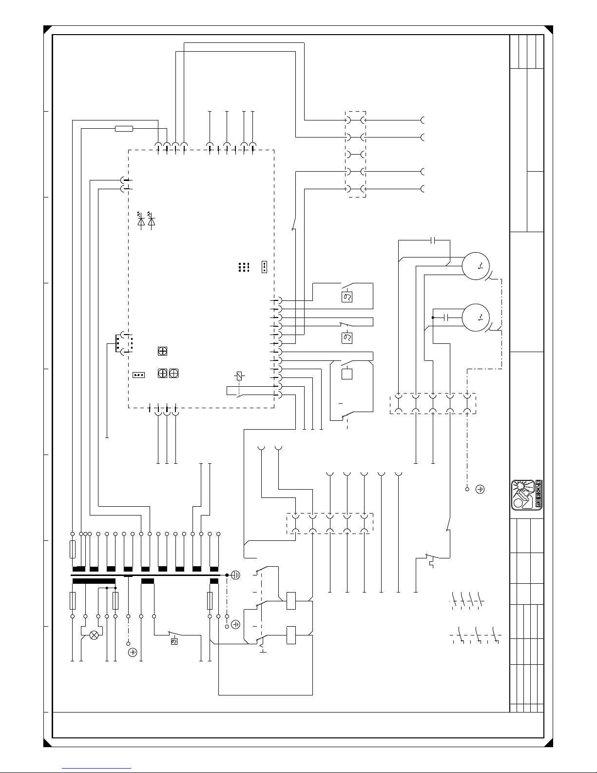
1 2 3 4 5 6 7 8
-T2
sw1/sw2
w2-9V
w2-0V
400V
230V
0/230V
0/230V
0V
w3-0V
w3-37V
w3-42V
w4-18V
w4-0V
w5-9V
W5-0V
w6-9V
w6-0v
w7-18V
w7-0V
w8-18V
w8-0V
w9-18V
w12-42VPEw12-0V
w11-9V
w11-0V
w10-9V
w10-0V
w9-0V
w1
5A1A1A2A1A1A1A
1A
1A
1A
-F2
4At
-F3
10At
-F1
1At
-F5
Trafo-Pr.
-F4
1At
-H1
-X11
PE
+SQ-A1-X3:1/2.4
+SQ-A1-X3:2/2.4
+SQ-A1-X3:3/2.4
1 2
123
4
1
3
5
6
+OP1-A2-X1
1.7
346789101112 5
1
2
3
12
-F6
-F7
-R1
16
17
18
23
-X3
24
-M2
PE
bl
schw
br
M
-M3
PE
bl
schw
br
M
-X5
55
11
22
33
44
-C1
-X11
PE
+SQ-A1-X1:1/2.7
+SQ-T2:w1-0/230V/2.2
+OP3-A3-X2:3/3.6
+OP3-A3-X2:4/3.6
+SQ-T2:w1-230V/2.2
-X2
1
1
2
2
5
5
3
3
4
4
129
-X3
10
-F9
+SQ-X2:17/2.7
+SQ-Q1:T2/1.2
+SQ-Q1:T1/1.2
+SQ-X5:2/2.4
+SQ-A1-X1:3/2.7
+SQ-A1-X1:6/2.7
+SQ-A1-X1:5/2.7
+SQ-A1-X2:11/2.4
+SQ-A2-X4:1/1.6
+SQ-A2-X4:2/1.6
+SQ-X8:2/1.4
+SQ-X8:1/1.4
+SQ-T2:w12-42V/2.2
+SQ-T2:w2-9V/2.2
+SQ-F5/2.1
+SQ-T2:230V/2.2
+SQ-X5:3/2.4
-A1
ME-MAG-5.1C
ge
Störung
failure
rt
T>
min P5
max P6
213
4
X3
5 12346789101112
X2
1 2
X6
X4
21345
6
X1
X5
4
3
2
1
JP2
HI
T-OFF
Lüfter/fan
Brennert.
torch switch
Wasser
water
Lüfter ein/fan on
Lüfternachlaufzeit/fan after-run time
Lüfterumschaltung/fan switching
ZÜNDV
soft start
JP1
ZV
ein/on
aus/off
+SQ-X2:16/2.7
+SQ-X2:18/2.7
-F8
P
+OP7
-S4
10
11
12
+OP7
-K2
11 12
-X2
7 7
8 8
16 16
17 17
18 18
-X11
PE
-K1
A1
A2
+OP7
-S4
1
2
3 4
5
6 7
8
9
+OP7
-K2
A1
A2
7
-X3
8
+OP7
-K2
31 32
bl-ws
bl-sw
vio-ws
or-ws
sw-gn
gn
rs
vio
ws
br
or
ge
vio-ge
gn-sw
vio-sw
bn
ws-bn
gr
sw
br
ws-rt
ws-bl
br-ws br-ws
br-gn br-gn
br-sw br-sw
sw-rt
bl-ws bl-ws bl-ws
sw-ws
bl-sw
or
vio-sw
bl-gn
ge
vio-ge
bl-gn
or-sw
vio-ws
sw
bl-sw ws-bl
br
ws-sw
vio-sw
br-sw
vio-ge
br-gn
br-ws
or-sw
sw
gr
gr
bl-rt
ws
sw
gn-sw
sw
gn-ws
.3
.7
.1
.2.2.4
.1
11
12
14
.3
21
22
24
31
32
34
.6
.1
1 2
3 4
/1.4
/1.4
/1.4
5 6
13 14
Flachbandkabel
flat band cable
Gleichrichter
rectifer
Pumpe
pump
Lüfter
fan
Option:
Fugenhobeln
Blatt
4
Bl.
2
Projektbez.
Auftragsnr.
Zeichnungsnr.
M451DW
Änderung
Datum
gez.
gepr.
Name
Datum
Name
Konrad
10.03.99
Siegner
30.03.99
Steuerstromkreis
Vervielfältigung oder Weitergabe nur mit unserer schriftlichen Genehmigung gestattet
c
dab
Plotdatum:
20.05.03
Merkle
Schweißanlagen-Technik GmbH
Industriestraße 3
D - 89359 Kötz
Telefon 08221 -915 - 0
Telefax 08221 - 32596
=
+
SQ

1 2 3 4 5 6 7 8
1
2
3
4
5
6
-X4
12
-Y1
3456789101112131415161718192021222324
1234567891011121314151617181920212223
+VB
-X4
24
+VB
-X3
1234567891011121314151718192021222324 16
A
+OP3
-X6
B
K
+
-
M
=
E
A
S
H
+VB
-X12
-X13
1
-X1
+
A
B
-M1
+
-
M
=
J
+OP3
-A3
rt
Freigabe/
enable
X4
ME-PPMR-2.1
X1
1
2
3
4
5
678
X2
1
2
3
4
5
6
1 10
X3
JP1
JP2
>3m
1A-träge/
slow
D
C
+OP2
-S2
1
2
3
Hand/Automatik
hand/automatic
+OP2
-X7
1
Option:
Automatenanschluß
machine welding connection
23456
+OP5
-M4
+
-
+
-
Motor für Option: DV-30
motor for option: DV30
G
=
M
=
+OP1-A2-X2:1/1.6
+OP1-A2-X2:2/1.6
+SQ-X2:3/2.7
+SQ-X2:4/2.7
+SQ-A1-X2:7/2.5
+SQ-F8/2.5
+OP3
-A4
ME-PPMR/AN 2.0
rt
+
rt
gn
0
-
110
X1
+SQ-T2:w3-0V/2.2
+SQ-T2:w3-42V/2.2
+SQ-X3:24/2.3
+SQ-X3:23/2.3
+SQ-X2:1/2.7
+SQ-X2:2/2.7
+OP6
-S3
1
2
3
+SQ-V1:+/1.4
+SQ-V1:-/1.4
+OP1-A1-X4/2.5
+OP6
-A6
+
-
2 13
X2
X3
10 1
10 1
Display
MAG
Uist
X4
X1
ME-MAG-5/ZW1
+OP1-A2-X1/1.7
+OP3
-S1
4
5
6 1
2
3
-R2
E
A
S
vio
ge
or
rs
vio
ws
br
bl
rt
bn
ws
vio-ge
vio-sw
ws-br
ws-rt
gn-sw
gn-ws
gn
rt
VB-Kabel
DV-Gerät
wire feeder
BT.
Drahtvorschub
wire feed
PP-Motor
D
C
J
K
A
B
H
BT.
Option:
PP-Brenner oder
Fernregleranschluß
pp-torch or
remote control
DV-25
Brenner
torch
+DV
-X4
12
Flachbandkabel
flat band cable
Draht
Spannung
Flachbandkabel
flat band cable
Option:
Anzeige umschaltbar
Volt oder m/min
Dieser Schaltplan gilt auch bei M 551DW
Blatt
4
Bl.
3
Projektbez.
Auftragsnr.
Zeichnungsnr.
M451DW
Änderung
+OP3-S1
Datum
gez.
gepr.
Name
Datum
Name
Konrad
11.03.99
Siegner
30.03.99
Konrad
25.09.01
Automatenanschluß
Option:Push-Pull,
Vervielfältigung oder Weitergabe nur mit unserer schriftlichen Genehmigung gestattet
c
dab
Plotdatum:
20.05.03
Merkle
Schweißanlagen-Technik GmbH
Industriestraße 3
D - 89359 Kötz
Telefon 08221 -915 - 0
Telefax 08221 - 32596
=
+
DV

17th7 Spare part list M 551 DW
electr. description part no.
-A0 pc board ME-EMV-1.3 (supply voltage filter) 03000070
-A1 pc board ME-MAG-5.1 C 00300514
-A2 pc board ME-MAG-5.1 DIS (option digital display) 00300516
-A3 pc board ME-PPMR-2.1 00300493
(option push pull and remote control)
-A4 pc board ME-PPMR/AN-2.0 00300485
(option push pull and remote control) 01001615
-A5 LEM converter HTA 400-S (option digital display)
-C1 capacitor 6 uF, 420V/AC 00100425
-F1 fuse 4 A, slow 6,3x32 00301251
-F2 fuse 4 A, slow 6,3x32 00301251
-F3 fuse 10 A slow 5x20 00301199
-F4 fuse 1 A 5x20 00301212
-F5 temperature switch 112 °C opening 00100408
-F6 temperature switch 80°C opening 00100406
-F7 temperature switch 40°C closing 00100345
-F8 water pressure switch 0,5 bar 00400204
-F9 thermical current protector 1,4 A 00300320
-H1 control lamp 230 V 00301238
lamp holder green 00301239
-K1 contactor A 50-30-10 42V 50/60 Hz 02011500
-L1 choke M 551 DW 00101931
-M1 wire feed motor 42V-DC (DV 30) 00202512
-M2 fan 230V 00101301
-M3 water pump 230V 50Hz 00400530
-S1 switch HLT 40/3ZM//NR 00100020
-S2 switch WAM 532/40E/Z11 coars selector 00100029
-S3 switch WAM 531/40E/Z11 fine selector 00100030
-R1 resistor 0,33 ohm 50 watt 03008612
-R2 potentiometer 10 kohm 00100502
-S1 switch 2-polig 00300900
-S2 switch 2-polig (option automated welding) 00300900
-T1 Main transformer M 505 DW 00101930
-T2 control transformer El 120/73, 7 950VA 00300242
-T3 current converter (green) 02011124
53

electr. description part no.
-V1 rectifier 550 A 00100250
-X1 Euro connector 01200287
-X2 connector 1,5/2,5, 5 pol. 01700617
-X3 female connector 24 pol. 01500501
-X3 male connector 24 pol. 01500500
-X4 male connector 24 pol. 01500500
-X4 female connector 24 pol. 01500501
-X5 connector 1,5/2,5, 5 pol. 01700617
-X6 socket 10-pol. 02110386
(option push pull and remote control)
-X7 male connector 6-pol. (option automated welding) 01500102
-X9 socket 70/95 mm² 500 A 00101102
-X10 socket 70/95 mm² 500 A 00101102
-X12 socket 70/95mm² 500A 00101102
-X12 plug DIX SE 50/70 01201508
-Y1 gas valve 42V/AC 00201602
-Z2 protection device 00300333
-Z3 protection device 00300334
17.8 Wiring diagramm M 551 DW
54
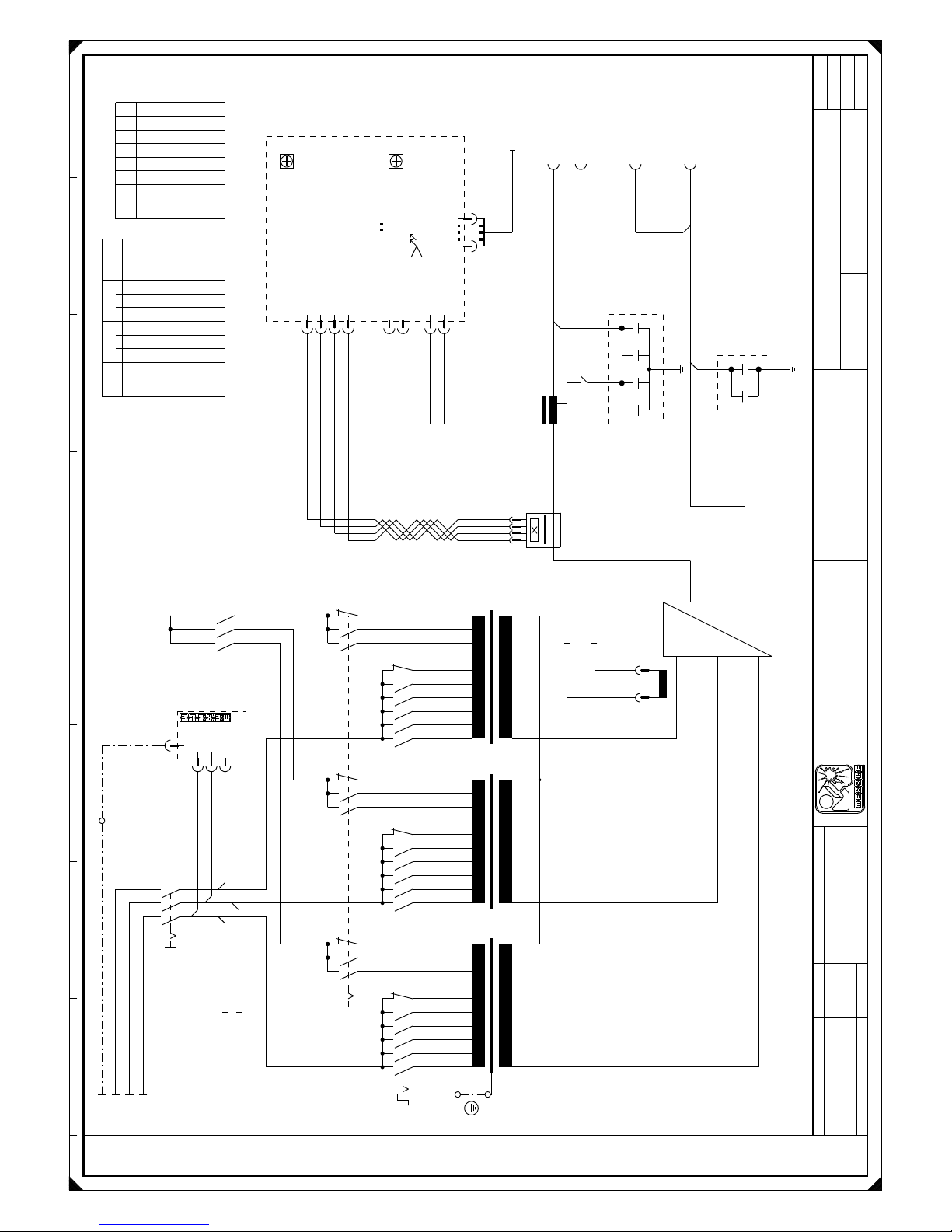
1 2 3 4 5 6 7 8
-T1
PE
~ ~ ~
U1
U2
U3
U4
U5
U6
U7
U8
U9
V1
V2
V3
V4
V5
V6
V7
V8
V9
W1
W2
W3
W4
W5
W6
W7
W8
W9
-Q2
L1 L2 L3
1 2 3 4 5 6 1 2 3 4 5 6 1 2 3 4 5 6
-Q3
R2
S2
T2
2 4 6 8 10 12 14 16 18
1 3 5 7 9 11 13 15 17
-K1
2
1
4
3
6
5
-A0
ME-EMV-1.3ME-EMV-1.3
L1L2L3
PE
-Q1
L1 L2 L3
T1 T2 T3
-X11
PE
-X11
PE
-T3
-V1
~
~
~
-
+
~
=
-L1
100%
66%
-Z2
123
4
+OP1
-A5
2 3 41
2
112
1
-X8
2
L2
L3PEL1
-Z3
+SQ-T2:w1-400V/2.2
+SQ-T2:w1-0V/2.2
-X10
-X9
-X12
+SQ-T2:w10-0V/2.2
+SQ-T2:w10-9V/2.2
+OP2-X7:2/3.7
+OP2-X7:1/3.7
+OP1
-A2
P1
NO
Hold
Draht
wire
Strom
current
P1
P2
ME-MAG-5.1/DIS
X2
rot
I>0
X3
X4
1
2
1
2
1
2
3
4
1 10
X1
1 2 3 4
+OP1-A1-X4/2.5
+SQ-A1-X2:10/2.4
+SQ-A1-X2:9/2.5
-X13
sw
sw-ws
sw-rt
br
ws
ws-sw
ws-bl
gn
gr
ws
sw
sw
sw sw
sw
sw sw
sw
sw
/2.2
3PH-400V/50-60Hz/PE
Q3
7 8 9 7 8 9 7 8 9
1234567
U
V
W
xxx
xxx
x
x
xxx
xxx
x
x
xxx
x
x
Q2
12345
6
1 2 3 4 5 6
x
x
x
x
x
x
Option:
Digitalanzeige
display
Option:
Digitalanzeige
display
-
-
Werkstück
work piece
+
+
Option:
Fugenhobeln
Blatt
4
Bl.
1
Projektbez.
Auftragsnr.
Zeichnungsnr.
M551DW
Änderung
Datum
gez.
gepr.
Name
Datum
Name
Konrad
10.03.99
Siegner
30.03.99
Konrad
16.12.99
Schweißstromkreis
Vervielfältigung oder Weitergabe nur mit unserer schriftlichen Genehmigung gestattet
c
dab
Plotdatum:
20.05.03
Merkle
Schweißanlagen-Technik GmbH
Industriestraße 3
D - 89359 Kötz
Telefon 08221 -915 - 0
Telefax 08221 - 32596
=
+
SQ

1 2 3 4 5 6 7 8
-T2
sw1/sw2
w2-9V
w2-0V
400V
230V
0/230V
0/230V
0V
w3-0V
w3-37V
w3-42V
w4-18V
w4-0V
w5-9V
W5-0V
w6-9V
w6-0v
w7-18V
w7-0V
w8-18V
w8-0V
w9-18V
w12-42VPEw12-0V
w11-9V
w11-0V
w10-9V
w10-0V
w9-0V
w1
5A1A1A2A1A1A1A
1A
1A
1A
-F2
4At
-F3
10At
-F1
1At
-F5
Trafo-Pr.
-F4
1At
-H1
-X11
PE
1 2
123
4
1
3
5
6
346789101112 5
1
2
3
12
-F8
P
-F6
-F7
-R1
16
17
18
23
-X3
24
-M2
PE
bl
schw
br
M
-M3
PE
bl
schw
br
M
-X5
55
11
22
33
44
-C1
+SQ-T2:w2-9V/2.2
+SQ-F5/2.1
+SQ-T2:230V/2.2
+SQ-X5:3/2.4
+SQ-A1-X3:1/2.4
+SQ-A1-X3:2/2.4
+SQ-A1-X3:3/2.4
+OP3-A3-X2:3/3.6
+OP3-A3-X2:4/3.6
+SQ-A1-X1:1/2.7
+SQ-T2:w1-0/230V/2.2
129
-X3
10
+SQ-A2-X4:1/1.6
+SQ-A2-X4:2/1.6
+SQ-X2:17/2.3
-A1
ME-MAG-5.1C
ge
Störung
failure
rt
T>
min P5
max P6
213
4
X3
5 12346789101112
X2
1 2
X6
X4
21345
6
X1
X5
4
3
2
1
JP2
HI
T-OFF
Lüfter/fan
Brennert.
torch switch
Wasser
water
Lüfter ein/fan on
Lüfternachlaufzeit/fan after-run time
Lüfterumschaltung/fan switching
ZÜNDV
soft start
JP1
ZV
ein/on
aus/off
+SQ-X8:2/1.4
+SQ-X8:1/1.4
+SQ-T2:w12-42V/2.2
+SQ-Q1:T2/1.2
+SQ-Q1:T1/1.2
+SQ-X5:2/2.4
+SQ-A1-X1:3/2.7
+SQ-A1-X1:6/2.7
+SQ-A1-X2:11/2.4
+SQ-A1-X1:5/2.7
+OP1-A2-X1/1.7
+SQ-X2:16/2.3
+SQ-X2:18/2.3
7
-X3
8
-F9
+SQ-T2:w1-230V/2.2
-X11
PE
-X11
PE
+OP7
-K2
11 12
-X2
7 7
8 8
16 16
17 17
18 18
-K1
A1
A2
+OP7
-S4
1
2
3 4
5
6 7
8
9
+OP7
-K2
A1
A2
+OP7
-K2
31 32
+OP7
-S4
10
11
12
bl-ws
bl-sw
vio-ws
or-ws
bl-gn
sw-gn
rs
vio
ws
br
ge
vio-ge
gn-sw
vio-sw
vio-ge
vio-sw
bn
ws-bn
gr
sw
br
ws-rt
ws-br
br-ws br-ws
br-gn br-gn
br-sw br-sw
sw-rt
bl-ws bl-ws bl-ws bl-ws
sw-ws
bl-sw
or
bl-gn
ge
or-sw
vio-ws
sw
bl-sw ws-bl
br
ws-sw
vio-sw
br-sw
vio-ge
br-gn
br-ws
or-sw
sw
gr
gr
bl-rt
ws
sw
sw
ge-ws
.1
11
12
14
.3
21
22
24
31
32
34
.6
.1
1 2
3 4
/1.4
/1.4
/1.4
5 6
13 14
.2.2.4
.1
Flachbandkabel
flat band cable
Gleichrichter
rectifer
Pumpe
pump
Lüfter
fan
Option:
Fugenhobeln
Blatt
4
Bl.
2
Projektbez.
Auftragsnr.
Zeichnungsnr.
M551DW
Änderung
Datum
gez.
gepr.
Name
Datum
Name
Konrad
10.03.99
Siegner
30.03.99
Steuerstromkreis
Vervielfältigung oder Weitergabe nur mit unserer schriftlichen Genehmigung gestattet
c
dab
Plotdatum:
20.05.03
Merkle
Schweißanlagen-Technik GmbH
Industriestraße 3
D - 89359 Kötz
Telefon 08221 -915 - 0
Telefax 08221 - 32596
=
+
SQ

1 2 3 4 5 6 7 8
1
2
3
4
5
6
-X4
12
-Y1
3456789101112131415161718192021222324
1234567891011121314151617181920212223
+VB
-X4
24
+VB
-X3
1234567891011121314151718192021222324 16
A
+OP3
-X6
B
K
+
-
M
=
E
A
S
H
+VB
-X12
-X13
1
+OP1-A2-X2:1/1.6
+OP1-A2-X2:2/1.6
+SQ-X2:3/2.3
+SQ-X2:4/2.3
+SQ-A1-X2:7/2.5
+SQ-F8/2.5
+OP2
-S2
1
2
3
Hand/Automatik
hand/automatic
+OP2
-X7
1
Option:
Automatenanschluß
machine welding connection
23456
-X1
+
A
B
J
-M1
+
-
+
G
=
M
=
+SQ-T2:w3-0V/2.2
+SQ-T2:w3-42V/2.2
+SQ-X3:24/2.3
+SQ-X3:23/2.3
+SQ-X2:1/2.3
+SQ-X2:2/2.3
+OP3
-A3
rt
Freigabe/
enable
X4
ME-PPMR-2.1
X1
1
2
3
4
5
678
X2
1
2
3
4
5
6
1 10
X3
JP1
JP2
>3m
1A-träge/
slow
D
C
+OP3
-A4
ME-PPMR/AN 2.0
rt
+
rt
gn
0
-
110
X1
+OP6
-S3
1
2
3
+SQ-V1:+/1.4
+SQ-V1:-/1.4
+OP1-A1-X4/2.5
+OP6
-A6
+
-
2 13
X2
X3
10 1
10 1
Display
MAG
Uist
X4
X1
ME-MAG-5/ZW1
+OP1-A2-X1/1.7
+OP3
-S1
4
5
6 1
2
3
-R2
E
A
S
vio
ge
or
rs
vio
ws
br
bl
rt
bn
ws
vio-ge
vio-sw
ws-br
ws-rt
gn-sw
gn-ws
VB-Kabel
DV-Gerät
wire feeder
BT.
Drahtvorschub
wire feed
PP-Motor
D
C
J
K
A
B
H
BT.
Option:
PP-Brenner oder
Fernregleranschluß
pp-torch or
remote control
Brenner
torch
DV-30
Flachbandkabel
flat band cable
Draht
Spannung
Flachbandkabel
flat band cable
Option:
Anzeige umschaltbar
Volt oder m/min
Blatt
4
Bl.
3
Projektbez.
Auftragsnr.
Zeichnungsnr.
M551DW
Änderung
+OP3-S1
Datum
gez.
gepr.
Name
Datum
Name
Konrad
11.03.99
Siegner
30.03.99
Konrad
25.09.01
Automatenanschluß
Option:Push-Pull,
Vervielfältigung oder Weitergabe nur mit unserer schriftlichen Genehmigung gestattet
c
dab
Plotdatum:
20.05.03
Merkle
Schweißanlagen-Technik GmbH
Industriestraße 3
D - 89359 Kötz
Telefon 08221 -915 - 0
Telefax 08221 - 32596
=
+
DV

18e EU-Conformity Attestation M 301
EU – Conformity Attestation
Description of the unit: MIG/MAG welding unit
Model: M 301 K / D
The above mentionned unit complies with the following European Regulations:
EU-Low Voltage Regulation 73/23/EWG
EU-Electromagnetic Compatibility 89/336/EWG
In case of any modifications, incorrect repairs not exclusively authorized by Merkle, this
attestation looses its valdity.
Applied norms EN 60974 - 1 / IEC 974 - 1 / VDE 0544 part 1
EN 60204 - 1 / IEC 204 - 1 / VDE 0113 part 1
EN 50199
Kötz, February 22th, 2001
Wilhelm Merkle, Generalmanager
Merkle Schweißanlagen-Technik GmbH
58

19e EU-Conformity Attestation M 351
EU – Conformity Attestation
Description of the unit: MIG/MAG welding unit
Model: M 351 K / D / KW / DW
The above mentionned unit complies with the following European Regulations:
EU-Low Voltage Regulation 73/23/EWG
EU-Electromagnetic Compatibility 89/336/EWG
In case of any modifications, incorrect repairs not exclusively authorized by Merkle, this
attestation looses its valdity.
Applied norms EN 60974 - 1 / IEC 974 - 1 / VDE 0544 part 1
EN 60204 - 1 / IEC 204 - 1 / VDE 0113 part 1
EN 50199
Kötz, February 25th, 1999
Wilhelm Merkle, Generalmanager
Merkle Schweißanlagen-Technik GmbH
59

20e EU-Conformity Attestation M 451
EU – Conformity Attestation
Description of the unit: MIG/MAG welding unit
Model: M 451 KW / DW
The above mentionned unit complies with the following European Regulations:
EU-Low Voltage Regulation 73/23/EWG
EU-Electromagnetic Compatibility 89/336/EWG
In case of any modifications, incorrect repairs not exclusively authorized by Merkle, this
attestation looses its valdity.
Applied norms EN 60974 - 1 / IEC 974 - 1 / VDE 0544 part 1
EN 60204 - 1 / IEC 204 - 1 / VDE 0113 part 1
EN 50199
Kötz, February 25th, 1999
Wilhelm Merkle, Generalmanager
Merkle Schweißanlagen-Technik GmbH
60

21e EU-Conformity Attestation M 551
EU – Conformity Attestation
Description of the unit: MIG/MAG welding unit
Model: M 551 DW
The above mentionned unit complies with the following European Regulations:
EU-Low Voltage Regulation 73/23/EWG
EU-Electromagnetic Compatibility 89/336/EWG
In case of any modifications, incorrect repairs not exclusively authorized by Merkle, this
attestation looses its valdity.
Applied norms EN 60974 - 1 / IEC 974 - 1 / VDE 0544 part 1
EN 60204 - 1 / IEC 204 - 1 / VDE 0113 part 1
EN 50199
Kötz, February 25th, 1999
Wilhelm Merkle, Generalmanager
Merkle Schweißanlagen-Technik GmbH
61

M E R K L E
Schweissanlagen-Technik GmbH
MERKLE
Schweissanlagen-Technik GmbH
Industriestrasse 3
D-89359 Koetz,
Tel.: ++49-8221-915-0
Fax: ++49-8221-915-40
www.merkle.de
Germany
2. Edition 2003 October 02th. 2003
Technical changes reserved
62
 Loading...