

OPERATION MANUAL
MIG/MAG Welding Unit
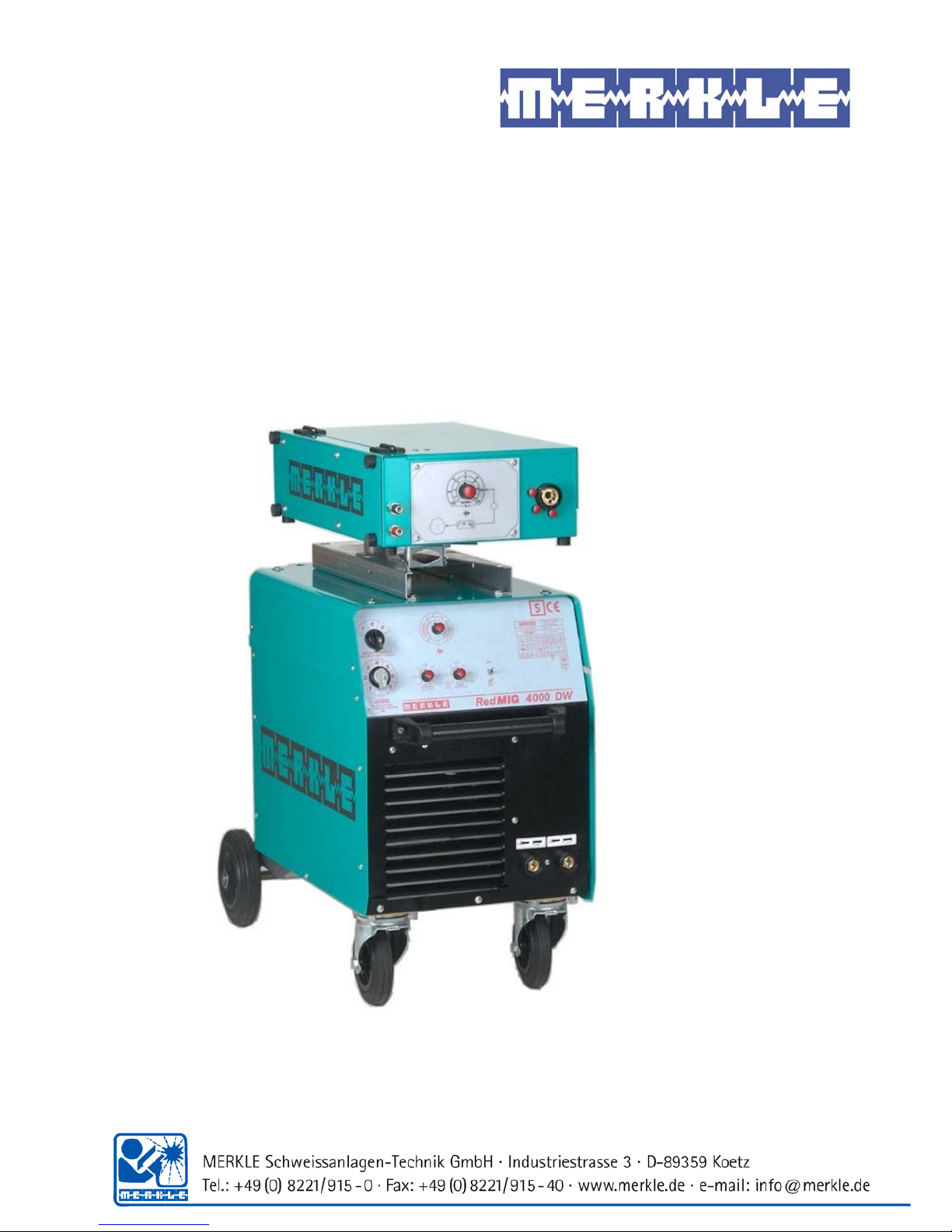
RedMIG 4000 DW

1

Content page
1st Security indications before introduction 4
2nd Accident prevention regulations 4
2nd1Safety instructions
4
3rd Duty cycle 6
4th Instructions to avoid interferences due to electromagnetic influences EMC 6
5th Technical Data 8
5th1MIG/MAG Welding Unit RedMIG 4000 DW
8
6th Start Up 10
6th1Installation of the Machine
10
6th2Main Supply
10
6th3Earth Lead (Work Cable)
10
6th4Welding Torch
10
6th5Gas Connection
10
6th6Wire Installation
10
7. MIG/MAG Series RedMIG 4000 DW 10
8th Adjustments 11
9th General Information MIG/MAG Welding Units 13
9th1Metal Inert Gas Welding (MIG)
13
9th2Metal Active Gas Welding (MAG)
13
9th2.1 Protective Gases 13
9th3Welding Wires
13
10th Options 13
10th1Welding Stainless Steel
13
10th2Welding Aluminium
13
11th Maintenance 14
12th Cleaning 14
13th Trouble Shooting 15
13th1Machine does not operate after switching on the main switch
15
13th2Machine does not react on the torch switch
15
2

13th3Control LED (red) is on
15
13th4Water pump is running, control LED (red) is on
15
13th5Control LEDs (yellow) and (red) are on
15
13th6Machine has no or too low welding current
15
13th7Welding quality is poor
15
13th8Problems with wire feeding and wire contacting
15
13th9Burning of the liner
15
14th General Information MIG/MAG Welding Units 16
14th1Metal Inert Gas Welding (MIG)
16
14th2Metal Active Gas Welding (MAG)
16
14th3Protective Gases
16
14th4Welding Wires
17
14th5Duty cycle
17
15th Wire feeder system 17
15th1Spare parts wire feeder model: DV-26
19
16th Welding-Torch and Spare parts 20
16.1Wiring diagramm RedMIG 4000 DW
24
17e EU-Conformity Attestation RedMIG 4000 DW 28
3

1st Security indications before introduction
The unit device is built after the recognized standards. Safe works are nevertheless only possible
if you read the operating instructions and the safety regulations contained in it entirely and
obey strictly. Install yourselves by trained staff of our establishments or appointed dealers.
2nd Accident prevention regulations
The following accident prevention regulation is applied for welding with MIG/MAG welding unit,
type RedMIG 4000 DW
BGV D1 (earlier VBG 15) * Welding, cutting and allied processes.
A copy of this regulation should be readily accessible in every welding shop. The stipulations of
this regulation are to be observed in the interests of safe and correct welding operation.
* Available from the trade association responsible or
Carl Heymanns-Verlag, Luxemburger Strasse 449, 50939 Cologne.
2nd1 Safety instructions
This unit is manufactured according to the requirements and stipulations of EN 60974.1 / VDE
0544 part 1. BGV D1 (earlier VBG 15) of the trade association for precision engineering and
electrical engineering are as well valid.
1) In case of an accident, the cutting unit must be disconnected from the mains
immediately.
2) If electrical contact voltages arise, switch off the unit immediately, disconnect it from
the mains and proceed to inspection by a qualified electrician or by our Service
Department.
3) Before opening the unit, disconnect it from the mains supply.
4) Repair work may only be carried out by a skilled electrician or by our Service
Department.
5) Before the unit is put to operation, check it visually, as well as the torch and all cables
and connectors regarding possible external damages.
6) Personal protective equipment in accordance with DIN EN 175, DIN EN 379 and
DIN EN 169.
During the work, the welder’s body must be completely protected against radiation and
burns by means of protective clothing and face protection. Long gloves, aprons and
welding shields with welding filters conforming to DIN EN 470-1 and BGR 189
must be worn.
Synthetic clothing are excluded. Shoes must be closed, not opened (due to spatters). If
necessary, protective headwear must be worn (e.g. for overhead welding). If cover
glasses are used, these must be in accordance with the norms specified above.
As additional protection for the eyes against UV radiation, safety goggles with side
shields and corresponding face protection in accordance with BGR 192 and BGI 553
must be worn.
Accident prevention regulation BGV D1 § 27 stipulates that it is the responsibility of the
employer to provide suitable personal protective equipment, while § 28 stipulates that it
is the responsibility of the insured to wear suitable clothing.
4

7) Protection when welding under increased electrical risks Welding rectifiers and welding
power sources which can optionally be used for either direct or alternating current must
be marked "S" in accordance with EN 60974-1 and BGI 534.
Use insulating materials to protect you against contact with electrically conductive parts
and damp floors. Wear dry, undamaged work clothing, long gloves and footwear with
rubber soles. Ventilate rooms, install extraction systems if required, and wear respiratory
protective equipment if necessary (see Procedural instructions BGV D1 § 27 and BGI 533,
Section 5).
8) In order to prevent stray currents and the effects thereof (e.g. destruction of electrical
protective ground conductors), the welding return cable (workpiece cable) must be
connected directly to the workpiece to be welded or to the table (e.g. welding table, gridtype welding table, workbench) supporting the workpiece (see BGV D1 § 20). When
installing the ground connection, assure that there is a good electrical contact (remove
rust, paint, etc.).
9) During welding pauses, the welding torch is to be laid down on an insulated surface or
hung up in such a way that it is not in contact with the workpiece and its support
connected to the welding power source (see § 20 BGV D1).
In the case of longer work pauses, the welding unit must be switched off and the gas
cylinder valve must be closed.
10) The shielding gas cylinder must always be protected against tumbling downing using a
safety chain.
11) Under no circumstances the unit may be put into operation while it is opened
(e.g. for repair work). Apart from the safety regulations, sufficient cooling of the
electrical components provided by the fan cannot be guaranteed.
12) In accordance with BGV D1 § 5, people in the vicinity of the arc must also be informed
of the hazards and protected against them. Safety partitions (“welding safety curtains”)
must be erected in accordance with DIN EN 1598.
14) N
o welding work may be carried out on containers in which gases, fuels, mineral oils or
similar substances have been stored Öeven if they have been empty for a long timeÕ
(risk of explosion). See § 31 of accident prevention regulation BGV D1.
15) Welds which will be subjected to high loads and which need to meet specific safety
requirements may only be carried out by specially trained and qualified welders.
15) Never bring the torch close to your face.
16) In areas at particularly high risk of fire, the welder must obtain a welding permit and
have this on his person throughout the duration of the welding work. On completion of
welding, a fire-guard must be delegated to ensure fire protection.
17) Ventilation measures must be applied in accordance with BGI 553, Section 9.
18) The hazard to eyesight must be indicated by means of a sign at the work site "CAUTION!
Do not look into the arc!".
5

3rd Duty cycle
The duty cylce measurings have been carried out in accordance with EN 60974-1 / VDE 0544
part 1 (10 min working period).
60% duty cycle means:
After a 6 min. welding period a 4 min welding pause must be respected. The electrical
components are thermally protected against overheating.
4th Instructions to avoid interferences due to electromagnetic influences EMC
The welding unit has been manufactured in accordance with the requirements of guideline
EN 50199 regarding electromagnetic compatibility. It is nonetheless the responsibility of the
user to ensure that the welding equipment is installed and operated in accordance with the
manufacturer’s instructions. If electromagnetic interference is detected, it is the responsibility of
the user of the welding equipment to find a solution with the technical assistance of the
manufacturer. In some cases, it may be sufficient simply to ground the welding current circuit.
In other cases, it may be necessary to build a complete shield for the welding power source and
workpiece using the input filters. In all cases, electromagnetic interference must be reduced to
avoid any possible malfunctions.
Note: For safety reasons, the welding current circuit may or may not be grounded. No
modifications may be made to the grounding without the approval of an expert who is able to
determine whether the changes might increase the risk of accidents, e.g. by allowing parallel
welding current return paths which could destroy the ground conductors of other equipment.
Further instructions are contained in TEC 974-XX "Arc welding equipment – installation and
use".
a) Evaluation of the installation site
Before installing the welding equipment, the user must evaluate potential
electromagnetic problems in the vicinity. The following must be taken into
consideration:
¾ Other power cables, control cables, signal and telecommunication cables above, below
and next to the welding equipment
¾ Radio and television transmitters and receivers
¾ Computers and other control devices
¾ The health of people in the vicinity, e.g. use of heart pacemaker and hearing aids
¾ Calibration and measuring equipment
¾ Interference immunity of other devices in the vicinity. The user must ensure the
electromagnetic compatibility of other devices used in the vicinity. This may require
additional safety measures.
b) Procedures to reduce emitted interference
1) Mains supply
Welding equipment is to be connected to the mains in compliance with the
recommendations of the manufacturer. If interference occurs, it may be necessary to
take additional precautions, e.g. filters for the mains connection. Make sure that the
power cable of welding equipment is installed in a fixed position shielded by means of a
metal conduit or similar. The entire length of the shield must be electrically connected.
The shield must be connected to the welding power source in the way to obtain a good
electrical contact between the metal conduit and the housing of the welding unit.
6

2) Maintenance of the welding equipment
Welding equipment must be maintained regularly in accordance with the
recommendations of the manufacturer. All access and service doors and covers must be
closed and fastened securely when the welding equipment is in operation. No
modifications whatsoever may be made to welding equipment with the exception of
modifications and adjustments specified in the manufacturer’s operating instructions.
3) Welding cables
Welding cables should be kept as short as possible and routed close together on or near
the floor.
4) Equipotential bonding
It is advisable to interconnect all metallic parts in and next to the welding equipment.
Metallic parts connected to the workpiece can, however, increase the risk of the welder
receiving an electric shock by touching these metallic parts and the electrode
simultaneously. The welder must be electrically insulated against all these connected
metallic parts.
5) Grounding the workpiece
If the workpiece is not connected to the ground for electrical safety reasons, or due to
the size and position of the workpiece, e.g. steel structure or outer wall of a ship,
grounding the workpiece may in some cases, but not all, reduce emitted interference. It
must be ensured that grounding the workpiece will not increase the risk of accidents for
the user and cannot cause the destruction of other electrical equipment. If necessary,
the grounding of the workpiece must be carried out by means of a direct connection to
the workpiece. In countries where a direct connection is prohibited, the connection must
be made by means of suitable reactors, selected in accordance with national regulations.
6) Shielding
Selective shielding of other cables and devices in the vicinity can reduce interference
problems. For special applications, it may be worth considering shielding the entire
welding system.
7

5th Technical Data
5th1 MIG/MAG Welding Unit RedMIG 4000 DW
Primary:
Voltage: 3 x 400 V
Frequency: 50/60 Hz
Continuous power: 10,4 kVA
Continuous current: 14 A
Max. current: 28 A
cos phi (280 A): 0,8
cos phi (150 A): 0,85
Secondary:
Open circuit voltage: 17 - 48 V
Welding voltage: 15 - 34 V
Welding current: 25 - 400 A
Duty cycle 35 % (10 min.): 400 A (40°C)
Duty cycle 40 % (10 min.): 400 A (20°C)
Duty cycle 60 % (10 min.): 330 A (20°C) 310 A (40°C)
Duty cycle 100 %: 250 A (20°C) 230 A (40°C)
Protection class: IP 23
Insulation: H
Cooling: AF
Mains switch: range 0-1-2
Voltage control: 14 steps
Operation modes: 2-/4-stroke/stitch/spot welding
Wire feed speed: potentiometer
Wire burn back: preset
Spot welding time: potentiometer
Intermission time: potentiometer
Control lamp: mains on
Rectifier: silicon press-in diodes
Choke: 1-step
Norm: EN 60974-1 "S" / CE
Torch cooling: integrated water cooler
Mains supply cable: 4 x 2.5 mm², 5 m long
with plug 3 x 400 V / 32 A
Gas bottle holder: 10, 20, 50 l cylinders
Gas hose: 2 m long
Socket 50 mm²: for earth lead
Lifting eyes: 4 pieces as option
Weight: 155 kg
Dimensions l x w x h: 940 x 445 x 1040 mm
8

Wire feeder: separately mounted, model DV-26
Supply: 26 V-DC
Wire feed motor:
DC motor with worm gear
drive
0.7 - 25 m/min.
Gear: 4-roller-drive DV-26
Wire feed speed: potentiometer
Wire feed support: D 300/15 DIN 8559
Torch connection: Euro connector
Weight: 18 kg
Dimensions: 610 x 400 x 180 mm
Connection cable: 1.6 m, 50 mm², water cooled
Standard wire equip.: mild steel 1.0 mm
9

6th Start Up
6th1 Installation of the Machine
Place the machine at least 0.80 m from a wall etc. to guarantee the cooling air can go
through the unit. The room temperature should not exceed 40°C.
The room were the unit is placed should have a low degree of humidity
(max. 50 % at 40°C, max. 90 % at 20° C).
The unit has passed the quality control in accordance with IP 21.
The air in the surroundings must be free from extreme quantities of dust, free from acides and
corrosive gases etc. Otherwise use air filters.
6th2 Main Supply
The main supply must be connected by a trained person. The main supply voltage is displayed on
the front or rear panel of the machine. A connection to protection earth must be done.
6th3 Earth Lead (Work Cable)
The earth lead must have an excellent ground. The clamp should be attached to a clean, paint
and rust free area on the work piece or on the welding table.
6th4 Welding Torch
Attach the hose assembly to the Euro-connector with the flange nut.
6th5 Gas Connection
Place the gas bottle on the gas bottle holder and secure it with the safety chain. Remove the
cap and open the bottle momentarily to purge the valve. Install the regulator on the bottle
valve. Connect the gas hose from the machine to the pressure reducer. Slowly open gas valve
and set the gas flow.
6th6 Wire Installation
Place the wire spool over the wire drive. Loosen the end and cut off the bent end
section. Hold the wire to prevent unwinding of the spool. Open the tightening lever and lift the
pressure finger. Feed the wire into the wire feed guide. Push the wire forward onto the wire
drive roller grooves. Close the tightening lever and switch on the machine.
Check the wire feeding: Place your hand 10 cm in front of the contact tip. Let the wire run into
your hand. If the wire is running, the pressure of the drive rollers is ok.
7. MIG/MAG Series RedMIG 4000 DW
The series RedMIG consists of step switched MIG/MAG welding units. The features are:
- Precise setting of the welding current due to max. 14 steps
- Selector: 2-stroke/4-stroke/stitch/spot welding
- Adjustable intermission and welding time
- 4-roller wire feeding system DV-26
- Approved of operation in confined areas, S-symbol
10

Front view:
8th Adjustments
Front view
Pos:1 main switch / coarse selector
Pos. 2 fine selector welding voltage.
Pos. 3 potentiometer wire feed speed
intermission timer, variable resistor with switch.
Interval welding: welding timer Pos. 2
intermission Pos. 3
Pos. 4 Selector “operation mode”, “gastest”
Pos. 5 Potentiometer “wire burn back”, “Timer intermission/ spot welding”
Pos. 6 LED “wire burn back setting”
Pos. 7 LED “time intermission/ spot welding”
11

Pos. 14 LED “over temperature”
Pos. 13 LED “machine switched on”
Operation mode 2-stroke:
As long as the torch trigger is pressed the unit is welding
Operation mode latch:
If the variable resistor “intermission” switch on but without timer, welding in
latch mode is possible
1. stroke-trigger pressed – welding ON
2. stroke trigger released
3. stroke trigger pressed – welding OFF
4. stroke trigger released
Operation mode interval:
The welding timer (pos. 2) is switch on by turning to the right. The welding
time is limited to the selected value.
By turning right this variable resistor ((pos. 3), the intermission time is activated.
The wire is running and welding current is ON as long as the torch trigger is pressed.
The gas comes out continously.
Operation mode spot welding:
The welding time is selected by variable resistor pos. 2. Once the trigger is pressed down,
the time starts running and at the end the unit cuts operation automatically.
For this mode a special gas nozzle is available. (see torch spare part list)
12

9th General Information MIG/MAG Welding Units
MIG/MAG welding is a system where the welding wire is the carrier of the electric arc.
Surrounding the contact tip (wire feed nozzle) is the gas nozzle, that emits the protective gas.
The welding bead is protected in this way from oxygen contamination.
9th1 Metal Inert Gas Welding (MIG)
In this technology inert gases are used. Mostly used are argon, helium, and mixtures of these
components. These gases do not react with other materials, they are inert. They are manly used
for welding aluminium, copper, titanium or other non ferrum metals.
9th2 Metal Active Gas Welding (MAG)
For MAG welding gases like CO2, argon, and mixtures of these components are
used. For special purposes also mixtures of C02, argon and oxygen can be used. Mild steel and
stainless steel is welded with theses gases.
9th2.1 Protective Gases
The gas flow is depended on several parameters:
- gas density
- material of work piece
- distance gas nozzle to work piece
- diameter of gas nozzle
- geometry of weld
For welding steel and stainless steel the gas flow is in the range of about 8 to 16 I at welding
currents of 40 -400 A. For welding aluminium the gas flow is about 30 % more.
9th3 Welding Wires
Different diameters of welding wires are available:
0.6 / 0.8 / 0.9 / 1.0 / 1.2 / 1.6 / 2.4 mm.
10th Options
10th1 Welding Stainless Steel
Exchange the parts according to the table listed in section “wire feeder” a Teflon liner
in the torch hose must be used. As gases we recommend mixtures of argon and
2.5 %CO2.
10th2 Welding Aluminium
Do not use wire diameters less than 1.0 mm. Max. length of the torch should not exceed 3 m.
Use Teflon liner in the torch hose. See section “wire feeder” for exchange of parts for welding of
aluminium.
13

11th Maintenance
The machine should be cleaned in regular intervals to guarantee a proper operation. The length
of the cleaning interval depends on the operation time, surrounding atmosphere etc.
IMPORTANT: Before opening the machine disconnect the main supply!
12th Cleaning
IMPORTANT: Before opening the machine disconnect the main supply!
Welding unit: Open the side covers. Remove dust from all parts of the machine.
Welding torch: Control the welding torch after welding of 50 kg wire.
Remove, clean and replace the wire core. Clean with a cleaning
solvent. Blow dry with compressed air. When replacing the wire
core, insure that there are no kinks. The gas nozzle must be
sprayed with a silicon-free spray to prevent the weld spatters
from sticking to the nozzle. The contact tip is a consumable item
and must be replaced as required.
Attention: Do put oil to the wire core or the drive roller on the
wire feed unit.
14

13th Trouble Shooting
13th1 Machine does not operate after switching on the main switch
a) Check main supply
b) Check main fuses
13th2 Machine does not react on the torch switch
a) Problem at the torch switch
b) Check internal fuses
13th3 Control LED (red) is on
a) Thermical protection switch for water pump is activated
b) Fuse is blown
13th4 Water pump is running, control LED (red) is on
a) Water pressure too low, check water level
b) Water pressure switch is not ok
13th5 Control LEDs (yellow) and (red) are on
a) Over temperature at transformer or rectifier. Wait for cooling down of the unit
13th6 Machine has no or too low welding current
a) Main contactor relays is not working
b) Bad or no contact at the earth lead
c) Torch hose completely or partially broken
d) Problem with rectifier in the machine
e) Only 2 main phases are connected, check main fuses
13th7 Welding quality is poor
a) No or not enough gas flow
b) Air is mixed into the protective gas. Open gas valve and close it again. Gas pressure must
remain in the gas hose. Check at the regulator.
c) Gas nozzle or tip holder are covered with spatters. Gas flow is not o.k.
d) Tip holder is not fixed properly. Air is mixed into the protective gas via the wire
e) Extremely oxidated work piece.
f) Air is coming to the welding area because of wind.
13th8 Problems with wire feeding and wire contacting
a) The hole in the contact tip has wrong diameter or contact tip must be changed.
b) Wire core is extremely dirty.
c) Kinks in the wire core.
d) Wrong diameter of the wire core.
e) Pressure at drive rollers is to low.
f) Wrong or old drive rollers.
g) Welding wire is not running in the axis of the drive rollers.
h) Mechanical resistance of the welding wire is too high.
13th9 Burning of the liner
a) Electrical connection between wire feed gear and welding current. Check wire
feeder for pieces of welding wire in the gear.
b) Check power cable or flange nut in the Euro-connector for a good connection.
15

14th General Information MIG/MAG Welding Units
MIG/MAG welding is a system where the welding wire is the carrier of the electric arc.
Surrounding the contact tip (wire feed nozzle) is the gas nozzle, that emits the protective gas.
The welding bead is protected in this way from oxygen contamination.
14th1 Metal Inert Gas Welding (MIG)
In this technology inert gases are used. Mostly used are argon, helium, and mixtures of these
components. These gases do not react with other materials, they are inert. They are manly used
for welding aluminium, copper, titanium or other non ferrum metals.
14th2 Metal Active Gas Welding (MAG)
For MAG welding gases like CO2, argon, and mixtures of these components are
used. For special purposes also mixtures of C02, argon and oxygen can be used. Mild steel and
stainless steel is welded with theses gases.
14th3 Protective Gases
The gas flow is depended on several parameters:
- gas density
- material of work piece
- distance gas nozzle to work piece
- diameter of gas nozzle
- geometry of weld
For welding steel and stainless steel the gas flow is in the range of about 8 to 16 I at welding
currents of 40 -400 A. For welding aluminium the gas flow is about 30 % more.
16

14th4 Welding Wires
Different diameters of welding wires are available:
0.6 / 0.8 / 0.9 / 1.0 / 1.2 / 1.6 / 2.4 mm.
14th5 Duty cycle
The duty cycle is measured at temperature of 40°C and a 10 minutes period. At lower
temperatures the duty cycle is higher.
15th Wire feeder system
17

18

15th1 Spare parts wire feeder model: DV-26
Pos. Bezeichnung Artikel-Nr.
1 Getriebewinkel DV-26 / Gear angle DV-26 113.584
2 MIG/MAG Zentralanschluss komplett / MIG/MAG Euro connector cmpl. 114.606
3 Isolierflansch DV-21 - 26 – 31 / isolation flange DV-26 113.572
4 Isolierbuchse DV-26,31,30/4 lang / isolation socket DV-26,31,30/4 long 111.052
5 Scheibe 5,3 Form B / plate 3,5 form B 090.0.1204
6 Linsenflachkopfschraube M 5x16 / allen key head screw M 5x16 090.1.0825
7 Gasnippel DV-26,31 / gas nipple DV-26,31 110.576
9 Linsenflachkopfschraube M 5x16 / allen key head screw M 5x16 090.1.0825
10 Isolierbuchse / isolation socket DV-26 113.568
11 Kappe rot für Drehknopf klein / Cap for knop 15 mm 003.0.1522
13 Rändelschraube GN 591 / Roller ring 110.568
14 Auslaufdüse / Outgoing nozzle DV-26 110.554
15 Isolierung / isolation DV-26 113.570
16 Wippe links / rocker left DV-26 110.538
17 Wippe rechts / rocker right DV-26 110.540
18 Bolzen SW 10 / bolt SW 10 for DV-26 113.576
19 Spring-Stop-Mutter M6x1x3,2 / spring washer M6x1x3,2 113.578
20 Gewindestange / threaded rod 110.546
21 Druckstück am Spannbügel / pressure piece on pressure lever 110.548
22 Druckfeder am Spannbügel / pressure spring on pressure lever 110.578
23 Druckschraube am Spannbügel / pressure screw on pressure lever 110.550
24 Linsenflanschkopfschraube M 5x16 / allen key head screw M5x16 090.0.0825
25 Zylinderstift 6 m6x32 / cylindrical dowel 6 M6x32 090.0.8460
26 Ritzel DV 26 / gear cog 113.580
27 Senkschraube M 4x12 mit Schlitz / counter sink screw M4x12 with slot 090.0.5815
28 Rosettenscheibe / rosett washer 090.0.1221
29 Motor DV-Getriebe / DC wire feed motor 002.0.2630
30 Linsenflanschkopfschraube M 6x12 / allen key head screw M5x16 090.0.0899
31 Bolzen DV 26 für Schutzabdeckung / bolt DV-26 for protective cover 113.582
32 Führungsstück / Guidance tube 113.566
33 Zyl-Schraube M 5x 12 verz. mit Innen-Skt 8.8 / cylinder screw M5x12 090.0.2565
34 Einlaufseele 0,14 m / Insertion sleeve, DV-25/4 012.0.0377
35 Antriebsring 1,0 + 1,2 Stahl / Drive ring steel 1.0 + 1.2 012.0.0272
36 Druckrolle / Pressure roller 113.742
37 Rollenbolzen / roller bolt 110.544
42 Rändelmutter / Guidance tube pvc 110.558
44 Zahnrad Z=19 m=2 / toothed wheel z=19 m=2 012.0.0263
45 Passstück 4x4x10 DV-30 für Zahnrad / adapter 4x4x10 for toothed
wheel
090.0.8810
46 Linsenflanschkopfschraube M 4x10 / allen key head screw M 4x10 090.0.0898
47 Schutzabdeckung für DV 26 / protection plate 113.586
48 Bolzen für DV 26 / bolt for DV-26 113.588
49 Spring-Stop-Mutter M6x1x3,2 / spring washer M6x1x3,2 113.574
50 Gewindestift M 12x16 / threaded bar with allen key head 113.574
19

16th Welding-Torch and Spare parts
Technical data:
Cooling: water cooled
Mixed gas: 400 A 60 % duty cycle
CO
2
: 450 A 60 % duty cycle
Wire diameter:
Solid wire: 0.8 – 1.0 – 1.2 – 1.6 mm ∅
Aluminium wire: 1.0 – 1.2 – 1.6 mm ∅
Weight: approx. 1340 g/1 m H
The data are corresponding to (U = 14 + 0.05 x I)
Torch model SB/SBT 502 W
MIG/MAG hand welding torch 022.1.1587
model SB 502 W, 3 m, short version
MIG/MAG hand welding torch 022.1.1588
model SB 502 W, 4 m, short version
MIG/MAG hand welding torch 022.1.1581
model SB 502 W, 3 m, long version
MIG/MAG hand welding torch 022.1.1582
model SB 502 W, 3 m, long version
MIG/MAG hand welding torch 022.1.1601
TEDAC, SBT 502 W, 3 m, short vers.
MIG/MAG hand welding torch 022.1.1602
TEDAC, SBT 502 W, 4 m, short vers.
MIG/MAG hand welding torch 022.1.1603
TEDAC, SBT 502 W, 3 m, long vers.
MIG/MAG hand welding torch 022.1.1604
TEDAC, SBT 502 W, 4 m, long vers.
Standard wire equipment: mild steel 1.2
20

MIG Welding torch model SB/SBT 502 W, watercooled
21

Spare parts and consumables:
Pos. Description Part No.
1-6 Torch neck SB/SBT 502 W 022.1.1564
short version
1-6 Torch neck SB/SBT 502 W 022.1.1560
long version
2 Insulation sleeve for 022.1.1574
SB/SBT 502W
3 O-ring 14 x 4 VE 10 pcs 022.1.0077
4 Pressure sleeve for SB/SBT 502 W 022.1.1424
5 O-ring 12 x 4 VE 10 pcs 022.1.0076
6 water coat for SB/SBT 502 W 022.1.1572
7 Insualtion ring SB/SBT 502 W VE 10 pcs 022.1.1421
8 Tip holder SB/SBT 300/502 W VE 10 pcs 022.1.1578
9 Contact tip Cu-Cr-Zr 0.8 mm VE 10 pcs 045.1.1814
9.1 Contact tip Cu-Cr-Zr 1.0 mm VE 10 pcs 045.1.1815
9.2 Contact tip Cu-Cr-Zr 1.2 mm VE 10 pcs 045.1.1816
9.3 Contact tip Cu-Cr-Zr 1.6 mm VE 10 pcs 045.1.1817
10 Diffusor SB/SBT 502W, ceramic VE 10 pcs 022.1.1567
10.1 Diffusor SB/SBT 502, fibreglass VE 10 pcs 022.1.1568
11 Gas nozzle 17 mm VE 10 pcs 045.1.4300
with fastening ring
11.1 Gas nozzle 14 mm VE 10 pcs 045.1.4301
with fastening ring
11.2 Spot welding gas nozzle VE 10 pcs 045.1.4304
with fastening ring
11.3 Gas nozzle 21 mm heavy duty VE 10 pcs 045.1.4305
with fastening ring
12 Contact tip AL/VA 0.8 mm VE 10 pcs 045.1.1812
12.1 Contact tip AL/VA 1.0 mm VE 10 pcs 045.1.1810
12.2 Contact tip AL/VA 1.2 mm VE 10 pcs 045.1.1811
12.3 Contact tip AL/VA 1.6 mm VE 10 pcs 045.1.1813
15 Handle MIG, complete 105.016
with trigger and cover cap
Only for SBT 502 W:
16 TEDAC pc-board ME-BE-10.0 022.1.0800
incl. slide switch and micro switch
18 Trigger for MIG/MAG torch 022.1.0796
19 Micro switch MIG/MAG torch 022.1.0797
20 Spring for switch VE 10 pcs 022.1.0131
21 Complete cable assembly, w.c. 022.1.1642
3 m, with Euro-connector,
without torch, without liner
21.1 Complete cable assembly, w. c. 022.1.1644
4 m, with Euro-connector,
without torch, without liner
22 Water-power-cable 3.0 m long 022.1.0281
22.1 Water-power-cable 4.0 m long 022.1.0282
23 Wire feeding hose cpl. 3.0 m long 022.1.1662
23.1 Wire feeding hose cpl. 4.0 m long 022.1.1664
24 Water hose flow, 3.0 m long 022.1.0290
24.1 Water hose flow, 4.0 m long 022.1.0291
25 Gas hose, 3.0 m long 022.1.0300
22

Pos. Description Part No.
25.1 Gas hose, 4.0 m long 022.1.0301
26 Switch-cable, 3 m long 022.1.0148
26.1 Switch-cable, 4 m long 022.1.0149
27 Protective-hose, 3.0 m long 006.0.1055
27.1 Protective-hose, 4.0 m long 006.0.1054
28 Liner for steel (blue) 022.1.0246
0.6 - 0.8 (1.0) mm, 3 m long
28.1 Liner for steel (blue) 022.1.0247
0.6 - 0.8 (1.0) mm, 4 m long
28.2 Liner for steel (uncoated), 022.1.0248
1.0 - 1.6 mm, 3 m
28.3 Liner for steel (uncoated), 022.1.0249
1,0 - 1.6 mm, 4 m
30 Euro-connection, at torch side 025.1.0150
31 Brass neck for Euro-connection 025.1.0200
32 Kinking-protection, intake 025.1.0100
33 Euro adapter nut 025.1.0300
34 Liner nut VE 10 pcs 025.1.1301
35 Water-return-hose 022.1.0295
36 Coupling nipple no. 3305 025.1.0400
37 Teflon liner for alu and stainl.st. 022.1.0586
0.8 - 1.2 mm, 3 m (red, 2.0 x 4.0)
with brass outgoing liner
37.1 Teflon liner for alu and stainl.st. 022.1.0588
(1.2) - 1.6 mm, 3 m (black, 2.7 x 4.7)
with brass outgoing liner
38.1 Collet for teflon liner 2.0 x 4.0 min 10 pcs 107.554
38.2 Collet for teflon liner 2.7 x 4.7 min 10 pcs 102.997
39.1 Outgoing nozzle pvc, DV-25/4 103.001
for aluminium and stainless steel
39.2 Outgoing nozzle pvc, DV-30/4 102.998
for aluminium and stainless steel, 0.8 - 1.6 mm
1.2 - 1.6 mm, 3 m (2.7 x 4.7 mm)
41 Kinking protection 022.1.1580
42 Spring for kinking protection 022.1.1579
43 Connection nipple for VE 10 pcs 045.1.0201
water-current-cable, torch side
44 Nipple for wire feeding hose at VE 10 pcs 045.1.0312
torch side
Protection hose 26 x 1.5 VE 120 m 027.2.0100
Water hose blue 5 x 1.5 VE 100 m 027.2.0130
Water hose red 5 x 1.5 VE 100 m 027.2.0125
PVC hose with textile 9 x 12 mm VE 100 m 006.0.0103
Only for SB 502 W:
45 Cover cap for TEDAC handle 022.1.0604
* max. length of torch lead for alu: 3 m.
23

16.1 Wiring diagramm RedMIG 4000 DW
24

1 2 3 4 5 6 7 8
-K1
12345
6
-Q1
15 13 11 7 9 5
14/16
8/12 6/10
0
1 2
-T1
1-sw
2-sw
6-sw
7-sw
8-sw
1-bl
2-bl
6-bl
8-bl
7-bl
1-br
2-br
6-br
7-br
8-br
~
~
~
PE
Violett
Braun
Schwarz
-Q4
1
3
5
7
9
11
13
15
17
Stufe 1-7
T2
S2
R2
L1L2L3
PE
Erdungsschraube
Erdungsschraube
-V1
~
~
~
+
-
~
=
-X9
-X10
-L1
100%
66%
-Z1
-Z2
+SQ-A1-X1:4/2.4
-X1
+
-Q1
241
3
+SQ-T2:400V/2.5
+SQ-T2:0V/2.5
sw
sw
bl
sw
sw
sw
sw
/2.3
.3
.2
3PH-400V/50-60Hz/PE
--
Werkstück
work piece
Blatt
4
Bl.
1
Projektbez.
Auftragsnr.
Zeichnungsnr.
REDMIG 4000DW
Änderung
Datum
gez.
gepr.
Name
Datum
Name
Konrad
21.10.06
Schweißstromkreis
Vervielfältigung oder Weitergabe nur mit unserer schriftlichen Genehmigung gestattet
c
d
a
b
Plotdatum:
11.05.07
Merkle
Schweißanlagen-Technik GmbH
Industriestraße 3
D - 89359 Kötz
Telefon 08221 -915 - 0
Telefax 08221 - 32596
=
+
SQ

1 2 3 4 5 6 7 8
-X11
55
11
22
33
44
-C3
-M3
PE
bl
schw
br
M
Erdungsschraube
-F4
10At
-F3
1A
-F10
1A
-F2
4A
-F1
4A
-T2
0V
400V
230V
PE
0V
42V
0V
37
440V
400
2,5A0,5A
Erdungsschraube
-M4
PE
bl
schw
br
M
-X12
55
11
22
33
44
-F9
Erdungsschraube
+SQ-Q1:3/1.3
+SQ-Q1:1/1.3
-F5
-F6
-K1
A1
A2
1
2
8
18
10
9
7
16
17
-X3
5
6
-S3
21
+SQ-X10:-/1.8
5
4
3
2
1
4
3
2
1
4
3
2
1
2
1
321
-A1
MAG30-AM1
1 2 1 2 3
1 2 3 4
1
2
3
4
1
2
3
4
1
2
1
2
3
4
5
3
X8 X9
X14
X1
X2
X5
X7
Poti
extern
VCC
GND
AD
Übertemp
+
Tedac
+
Anker
Werkstück
Brenner
GND
VCC
SDA
SCL
GND
37VAC
+
-
Tacho
Schütz
Gasventil
1
2
3
4
5
6
7
VCC
X6
Reset
SCK
MISO
MOSI
/SS
ISP
321
13
14
15
-F7
P
ws
bn bn bn
rs
ws
rs
ge
bn
gr
sw
ws
bn
ge
gr
bl
ws
ge
ge
rt
bl
sw
rt
rt
gr
bl
bl
or
or
rs rs
vio
vio
or
ge
rs
or
ge
gn
ge
vio
gn
1 2
3 4
/1.1
/1.1
/1.1
5 6
13 14
LÜFTER
FAN
Pumpe
pump
Trafo primär
Gleichrichter
rectifer
Wasserdruck-
schalter
Blatt
4
Bl.
2
Projektbez.
Auftragsnr.
Zeichnungsnr.
REDMIG 4000DW
Änderung
Datum
gez.
gepr.
Name
Datum
Name
Konrad
21.10.06
Steuerstromkreis
Vervielfältigung oder Weitergabe nur mit unserer schriftlichen Genehmigung gestattet
c
d
a
b
Plotdatum:
11.05.07
Merkle
Schweißanlagen-Technik GmbH
Industriestraße 3
D - 89359 Kötz
Telefon 08221 -915 - 0
Telefax 08221 - 32596
=
+
SQ

1 2 3 4 5 6 7 8
+OP3
-A8
rt
Freigabe/
enable
X4
ME-PPMR-2.1
X1
1
2
3
4
5
6
7
8
X2
1
2
3
4
5
6
1 10
X3
JP1
JP2
>3m
1A-träge/
slow
6
5
4
3
2
1
+SQ-A3-X9:1
+SQ-A3-X9:3
+SQ-X3:9/2.1
+SQ-X3:10/2.1
+SQ-A3-X8:1
+SQ-A3-X8:2
+OP2
-S2
123
Hand/Automatik
hand/automatic
+OP2
-X7
6
5
4
3
2
1
+SQ-T2:0V/2.5
+SQ-T2:37V/2.5
+OP3
-A7
ME-PPMR/AN 2.0
rt
+
rt
gn
0
-
110
X1
+SQ-X3:1/2.1
+SQ-X3:2/2.1
A
+OP3
-X6
B
K
H
-X1
+
A
B
J
D
C
+
-
M
=
E
A
S
-R2
E
A
S
-Y1
+VB
-X3
1234567891011121314151718192021222324 16
+VB
-X12
-X4
123456789101112131415161718192021222324
1234567891011121314151617181920212223
+VB
-X4
24
+SQ
-X3
24
23
+OP3
-S1
456 123
-M1
-
+
M
=
+OP4
-M1
-
+
-
+
G
=
M
=
321
-A4
1 2 3
X1
MAG30-MAT-1.1
vio-ge
vio-sw
sw-gn
gn
ge-sw
bn-ws
bn-gn
bl-ws
bl-rt
bl-gn
sw-ws
sw-rt
ws
ws
bl
or
gn
ge
gn-sw
bl
rt
vio-sw
vio-ge
ge
bn
Flachbandkabel
flat band cable
Option:
Push-Pull Anschluß
push-pull connection
DV-Gerät
wire feeder
Brenner
torch
BT.
Drahtvorschub
wire feed
PP-Motor
BT.
D
C
J
K
A
B
H
Option:
PP-Brenner oder
Fernregleranschluß
pp-torch or
remote control
VB-Kabel
DV-26
1234
X4
Option:
DV31
Blatt
4
Bl.
3
Projektbez.
Auftragsnr.
Zeichnungsnr.
REDMIG 4000DW
Änderung
Datum
gez.
gepr.
Name
Datum
Name
Konrad
21.10.06
Automatenanschluß
Option:Push-Pull,
Vervielfältigung oder Weitergabe nur mit unserer schriftlichen Genehmigung gestattet
c
d
a
b
Plotdatum:
11.05.07
Merkle
Schweißanlagen-Technik GmbH
Industriestraße 3
D - 89359 Kötz
Telefon 08221 -915 - 0
Telefax 08221 - 32596
=
+
DV

17e EU-Conformity Attestation RedMIG 4000 DW
EU – Conformity Attestation
Description of the unit: MIG/MAG welding unit
Model: RedMIG 4000 DW
The above mentionned unit complies with the following European Regulations:
EU-Low Voltage Regulation 73/23/EWG
EU-Electromagnetic Compatibility 89/336/EWG
In case of any modifications, incorrect repairs not exclusively authorized by Merkle, this
attestation looses its valdity.
Applied norms EN 60974 - 1 / IEC 974 - 1 / VDE 0544 part 1
EN 60204 - 1 / IEC 204 - 1 / VDE 0113 part 1
EN 50199
Kötz, April 24th, 2006
Wilhelm Merkle, Generalmanager
Merkle Schweißanlagen-Technik GmbH
28

29
Notes:
1. Edition 2008 March 3th. 2008
Technical changes reserved.
 Loading...