

USER MANUAL
LogiTIG
240 AC/DC
200 AC/DC


Content
1 The LogiTIG 200 AC/DC and 240 AC/DC
1.1 Intended Purpose
1.2 Transport
1.3 Positioning in the work place
1.3.1 Positioning
1.3.2 Use in conjunction with a power generator
1.3.3 Extension Cables
1.4 Start up Procedure
1.5 Illustration of the control panel and accessories attachments
1.6 Operation control in standard mode
2 TIG Welding
2.1 Process
2.2 Employment of the Process
2.3 Connection to the Mains
2.4 Joint preparation
2.5 Gas nozzle and welding current
2.6 TIG mode (standard operation)
2.6.1 Setting the welding current
2.6.2 TIG welding application
2.7 TIG Operation in standard mode
2.7.1 The DC welding mode
2.7.2 Alternating current (AC) welding mode
3 Electrode Welding (MMA Welding)
3.1 Process
3.2 MMA Preparation
3.3 Operation procedure
3.3.1 Display Details
3.3.2 Electrode Welding mode
3.4 Welding process
4 TIG – Expert Mode
5 Set-up Menu
6 Parameter adjustment range
7 Trouble shooting
8 Servicing
9 TIG hand welding torch – and spare parts

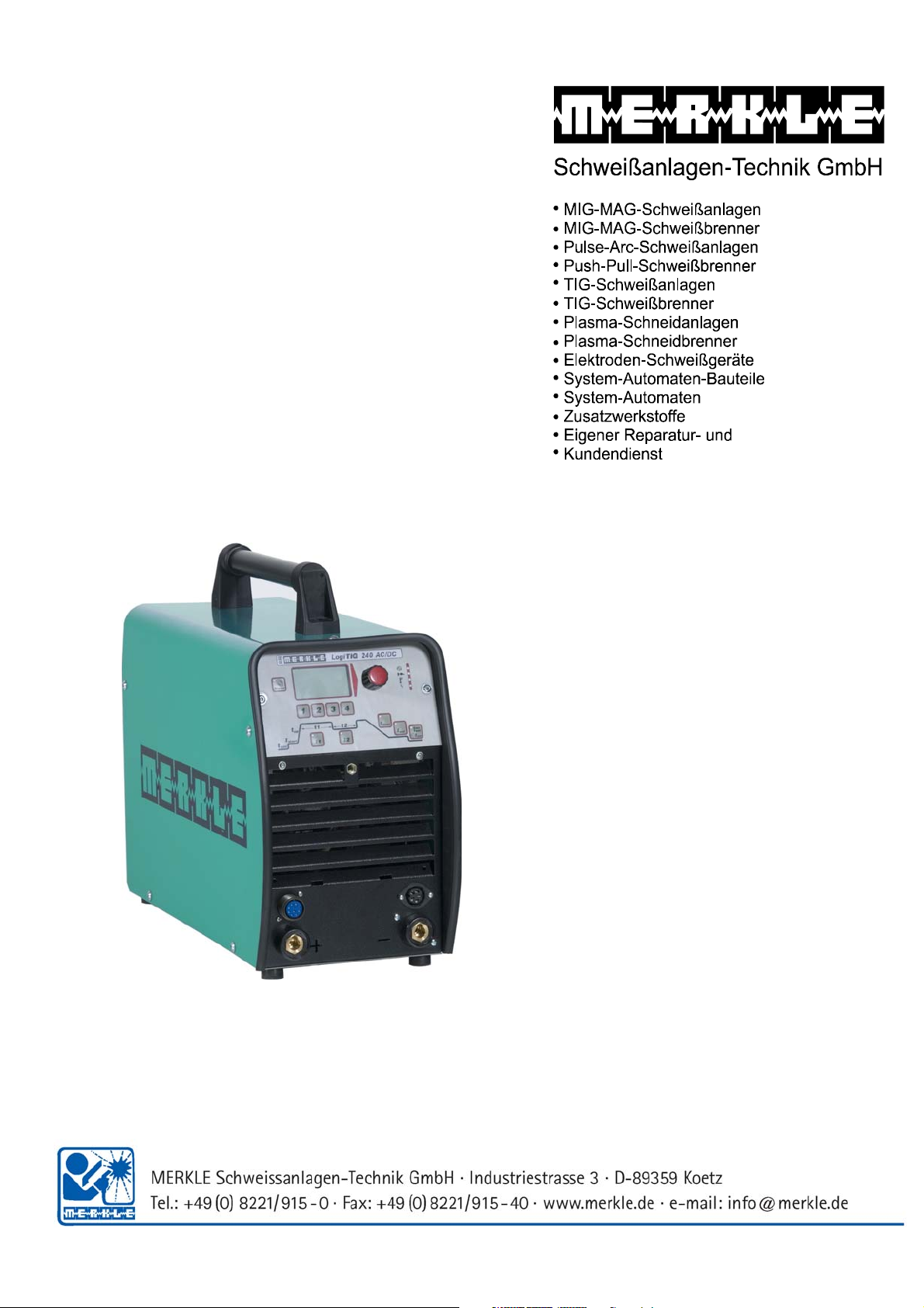
1. The LogiTIG 200 AC/DC and 240 AC/DC
The LogiTIG 200 AC/DC and the 240 AC/DC and are equipped with top of the line inverter
technology, they are designed to carry out the TIG and MMA welding processes in both AC and DC
current.
The welding machine is universally employable.
This series of machines lends itself well to on sight welding work. This is thanks high level of
mobility due to its extremely compact (space saving) design and reduced weight characteristics,
this coupled with the fact that it can also be run on a single phase 230V system (180A max)
1.1 Intended Purpose
This welding equipment it designed for the following processes
• MMA welding
• TIG welding with a shielding gas
All other processes undertaken with this machine are strongly ill advised and should not be
practised.
1.2 Transport
Before transporting this machine disconnect the gas line between the gas bottle and the welding
machine. During the transport make sure that the machine is secured in case of an accident.
DANGER:
• The gas bottle must be removed for the purpose of transportation.
• If not removed there is a danger of injury through falling gas bottles.
• DANGER OF EXPLOSION
1.3 Positioning in the work place
The machine should be placed in dry ambient areas and is designed only to be used in covered
protected environment.
Note:
• Never weld in open areas in the rain.
• Always check the proposed area for EMV activity
Should there be any disturbances then these must be eliminated before any
welding can take place.
• Danger is also present through electrically conductive components
• Isolation matting should be available for the protection of the operator from electric
shocks
1.3.1. Positioning
Attention
Cooling fans are employed in this machine to cool the power unit, therefore it is imperative that:
• Fresh air is allowed easy access to entry point (front) of the machine and the exiting air is
also free of any constricting obstacles.
• There should be an all round free space of approx. 80cm around the machine.
• In workshops with a high dust concentration an air filter should be employed on the
machine (optional extra).
• The machine should be placed on firm even ground.

• Ensure that the machine entry temperature is between -10 and +40°C
• Care should be taken to ensure that the rooms humidity is correct (up to 50% at 40°C and
90% at 20°C).
• The surrounding environment should be where possible free of excessive dust, acid and
corrosive gases.
• By higher concentrations of the above an air filter must be employed.
1.3.2. Use in conjunction with a power generator
• The power output of the generator should be at least 10% higher than the power intake of
the welding machine.
• The output voltage of the generator must also have a regulated open circuit voltage.
Switching on
First start the power generator and then switch on the welding machine.
Switching off
First switch off the welding machine and then the power generator.
By not adhering to the above advice YOU take the risk of damaging the machine through power
spikes.
1.3.3 Extension cables
Cautionary measures in the use of extension cables:
• The cable should be in a good and safe condition.
• The cable should always be fully removed from the cable drum.
• The maximum cable length should not exceed the conductor cross section value.
When these rules are not adhered to there is a real risk of overheating.
1.4 Start up Procedure
During the start-up process information about your machine is displayed on the Multi-Functional
display. You can according to the machine version various settings can be carried out.
• Start Process
• Turn the main power switch to position “I”.
• The software will be loaded and the Multi-Functional display (MFD) will show the
following information:
- Display version
- Machine version
- The last selected welding program
• During the start up process no setting changes can be made!
In the factory delivered condition the welding unit is set in “standard mode”. In this condition the
basic welding parameters are available. The operation is also simple. Should you require more
functions than are presently available then the machine can be switched to an “expert Mode”. The
procedure for this is explained in “Set-up menu” (chapter 7)

Special functions
• Resetting to factory settings (see Chapter 8)
Reset process explanation
• Colour adjustment of the MFD panel:
Select set-up menu
Press button I
1
The display panel background and script colour can be changed, i.e. black
/white to white/black
• Actual Welding Parameter will show all welding conditions one after the other
Press buttons I
and I2 together for 2 seconds.
1
• HIGH CURRENT / BIPOWER Technology (only LogiTIG 240 DC)
According to the power supply the maximum output available:
• Mains connection to 3 Ph 400 V-N-PE (32A):
TIG welding current up to 240A
MMA welding up to 200A
• With adapter 400/230V (16A)
TIG welding current up to 180A
MMA welding current up to 160A limited
• Duty Cycle (dc)
The Duty Cycle measurement is carried out according to EN 60974-1 / VDE 0544 in 10
Minute working cycles.
This has a value of 60% dc:
After a 6 minute welding period there must follow a 4 minute cooling phase.
The performance parts are Temperature controlled against overheating, after they have
switched off they will automatically re-activate when the temperature drops.
These values apply to working temperatures up to 40 °C and a maximum height above sea
of 1000m NN. Higher temperatures, attached air filters and higher altitudes will affect the
duty cycle values.
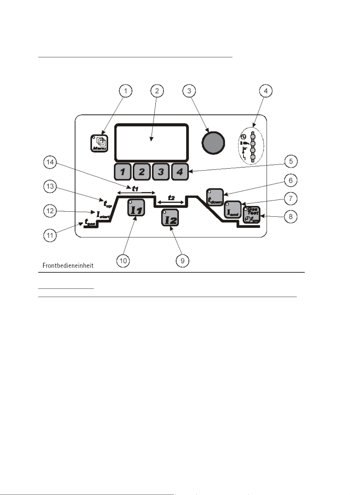
1.5 Illustration of the control panel and accessories attachments
Front panel controls
Position Sign Function___________________________________
1 Menu button button for Menu Functions (only in expert mode)
2 Display Panel shows Welding parameters
3 Incremental potentiometer endless rotary control for the setting of parameters
4 Status Display machine status and Warning indicators
5 Buttons 1-4 function buttons, module and menu functions
6 t
7 I
parameter buttons for setting of the down slope time
down
parameter button for setting the end current
end
8 Gas Test button for Gas test
9 I
10 I
11 t
12 I
13 t
14 t
parameter button for setting the 2nd welding current
2
parameter button for setting the 1st welding current
1
parameter button for setting the pre-gas flow time
gas
parameter button for setting the start current
start
up
and t2 parameter button for setting the I1and I2 current times
1
parameter button for setting the upslope time
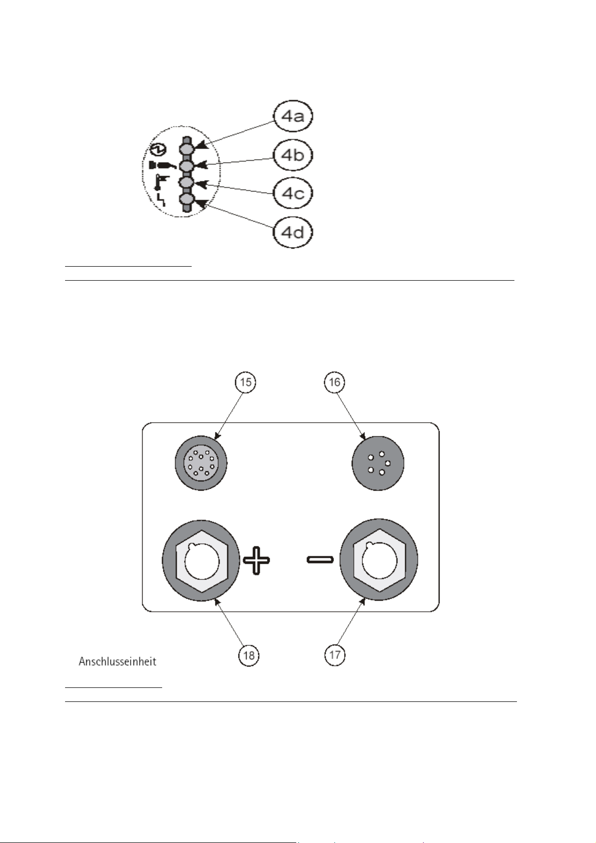
LED status/warning display
Position Sign Function _________________________________
4a Machine status display shows the machine has no-load current at the Poles
4b Network connection shows that the machine is switched on
4c Warning light temperature shows that the machine is overheating
4d Defect warning light shows that the machine has a defect
Connection adapters
Position Sign Function ____________________________
15 control cable remote control
16 control cable torch control
17 - Pole Busch TCG connection: combined Gas, TIG current and
MMA electrode holder
18 + Pole Busch Earth cable and MMA electrode holder connection
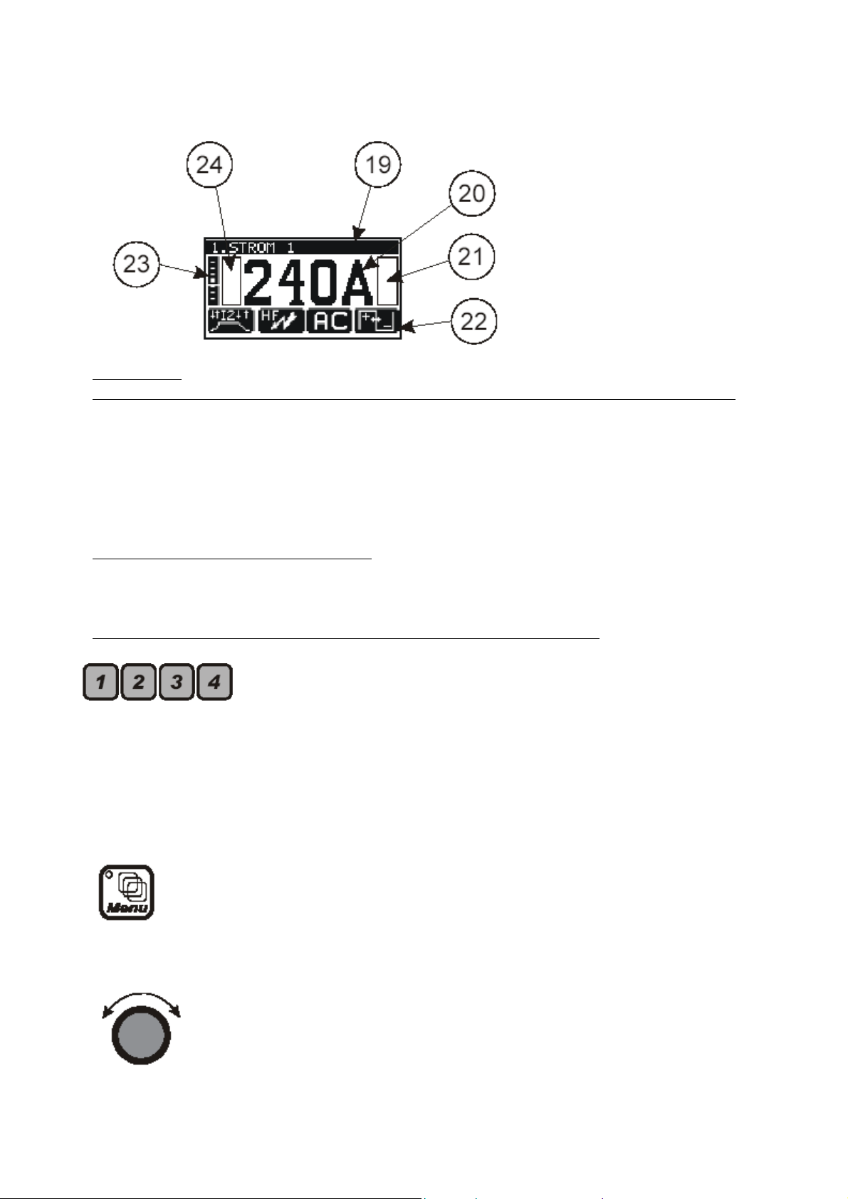
Display panel
Position Sign Function ____________________________
19 text field shows the parameter mode
20 parameter displays shows the actual parameter value selected
21 flag display field right shows the activated flags
22 pictogram line shows the selectable menus/modus functions
23 AC – balance scale graphic display for the AC balance value
24 flag display field left shows the activated flags
1.6 operation control in standard mode
The following diagrams clarify the function and pictogram in the display panel when used in the
standard mode of the welding unit.
Control button illustrations to be imported from the original document
Function buttons F1, F2, F3, and F4 for:
• Selection of the mode in connection with the pictogram on the
display, through the repeated use of the buttons.
• Selection of the parameters according to the pictogram in the
display and the adjustment of the values using the incremental
switch.
Menu button (in standard mode inaccessible)
• button for selection of the menu function
Incremental potentiometer
• continuous potentiometer without rotary limiter
• adjustment of the value of the selected parameter

Parameter button (PB) for the direct adjustment of the main welding
current I
. Integrated into the button is an LED.
1
• The LED button lights up:
When the current I
When the current I
is being adjusted
1
is active in the welding process
1
• If the main welding current I
welding current I
will adjust itself proportionately.
2
is adjusted, at the same time the
1
Parameter button (PB) for the adjustment of the welding current I2.
Integrated into the button is an LED.
• The LED button lights up:
When current I
is being adjusted
2
When the current I2 is active in the welding process
Should the I
welding current I
• The welding current I
current be altered, it will have no effect on the main
2
.
1
is only available in the following processes
2
Slow pulsing
Quick pulsing
4-stroke with current I
2
PB for the selection of the down slope t
is an LED.
• The down slope time of the welding current I
activated I
• Welding process with 2 welding currents I
• The function is active in:
PB for the selection of the end current I
is an LED.
• In the selected time the active welding current will be reduced until it
reaches the I
. Integrated into the button
down
until the end current is
1
end
and I2:
1
Both welding currents near themselves in the selected
time of the end current I
end
Pulse-setting
Stroke-modus
. Integrated into the button
end
current value.
end

PB “Gas-test”. Integrated into the button is an LED.
Warning light indicators
Setting the gas post flow
• Press button once
LED in button will light up
Post gas time can be set using the incremental parameter
Selecting the gas test function
• Press the button twice
LED in button will blink
The gas valve will open
The timer will run backwards
The gas valve will be closed automatically on reaching
zero
The gas valve can be manually closed by pressing the
button once more
After the completion of the gas test
The LED in the button will stay lit
Then the gas post flow can be set using the
incremental potentiometer
(as described in “gas post flow”)
Displaying the gas post flow function
• After the welding process has ended
The LED button will blink
The gas post flow will continue for the selected time
• Automatic purging of the gas line will follow:
When switching from MMA mode to TIG mode, when the
electrode is used.
During the running up of the welding unit whilst in TIG
mode.
Welding unit status indicator
• LED is lit
No load current is at the connecter bushes

Network connection status indicator
• LED lights up when:
The welding unit is connected to a mains adapter
The mains switch is switched on
Warning light – overheating of the power components
LED will blink when:
• The working temperature is 5°C before its critical limit is reached
• Advance warning that the welding process will be automatically
interrupted
LED is constantly lit
• Overheating temperature has been reached
• Before the welding process:
No welding process will be available until the unit has
cooled to a normal working temperature
• During the TIG welding process:
In 2-stroke and 4-stroke mode the welding current will be
reduced until it reaches the end currant. The welding
process will only be interrupted when the end current is
reached
With a foot control and an automated or robot unit the
program will be interrupted without the down slope
process being activated
Remote controls: if one of the following is in use: torch
trigger or foot control, the display panel will show the
following defect message, “release trigger”
• During the MMA welding process :
The welding process will be immediately interrupted
Defect warning light
This LED illuminates when there is a defect in the machine:
• Before the welding process has begun
No welding process possible
• During the TIG and MMA welding process
Welding process will be immediately interrupted
Warning lights and fault messages in the display unit
• “Release the trigger”
One of the following control elements is in use
Torch trigger, foot switch or control contact
• “Water pressure failure”

Flag Symbol
HOLD flag after the end of a welding process.
• The flag symbol shows the user that the welding parameters used
have been saved.
• The storage of the information is transient,
After an interruption the welding process will re-begin
with the same parameters.
Every parameter changed wipes the previously stored
parameter from the parameter settings.
The recalling of the previous weld settings through the
machine is then not possible.
• TIG welding parameters
The chosen parameters of the last used cycle before the
Down slope T
will be saved by the machines memory.
down
AC – Balance Scale
(The display is visible in conjunction with the TIG Modus function
“AC – Balance Amplitude”)
• The display is only visible in AC modus
• The vertical display represents the percentual share of the
positive half wave during the complete welding process (in
time).
• Indicator is positioned in the middle.
The positive and negative share of the wave is
identical.
• The indicator is positioned in the upper half of the scale
The positive half wave is larger than the negative half
wave
• Indicator in the lower half of the scale
The negative half wave is larger than the positive half
wave.
• One Pixel in the Horizontal translates to an adjustment of 3%.

2. TIG Welding
TIG Stands for Tungsten-inert-gas welding.
2.1 Process
A non consumable electrode made of tungsten or a tungsten alloy produces a welding arc. The
welding arc burns between the electrode and the work piece and is protected by an inert shielding
gas. The electrode and the molten pool are protected from the oxidising effects of the oxygen.
The inert gases used for this process are Argon; sometimes Helium or a mixture gas containing
both components can also be used.
The filler material is manually fed into the weld pool for manual welding process and mechanically
in the case of cold wire feed units.
2.2 Employment of the Process
The TIG process can be found employed joining foil and thin sheet together between 0.3 – 4.0mm
in one run, it is also used to join thicker pieces of material together (up to 12mm) when it can be
simultaneously welded from both sides. Thicker material would only be joined using the TIG
process when special technical demands dictate that TIG is the only process permit-able.
The TIG process produces a very high quality weld bead. The process therefore lends itself to
automatic welding as the process is easily controllable. In conjunction with special weld
preparations the process can be used on thicker materials for carrying out the root run. The
remainder fill and capping runs would be carried out using the MIG/MAG and Pulse-arc process.
2.3 Connection to the Mains
Mains connector
• Make sure that the machines main switch is in the “0” position
• The male connector is securely plugged into the correct mains current
Torch and hose assembly
• Combination connector (TGC-connector) must be connected to the minus pole (17)
connector.
• Turn the connector clockwise through 180
• The control socket should be connected plugged into socket 16 and secured using by
turning the twist connector until secure.
Earth return lead
• The earth return lead should be connected to the plus pole connector and turned
through 180º to secure.
• The earth clamp should then be secured to the work piece.
Gas bottle connection
• Lay the correct spanner for connecting the regulator within easy reach of the bottle.
• Remove the protective valve cap from the bottle.
• The gas valve should then be purged to remove all foreign bodies from the valve area.
• The gas pressure gauge connection should then be checked to see that it is also clean.
• The gas pressure gauge can now be screwed to the bottle and secured tightly using the
spanner. Make sure that the gasket ring in the valve nut is securely in place and not
damaged in any way. If so then replace with a new one.
º
to ensure secure connection.

2.4 Joint preparation
The TIG process requires that the weld joint is dry and free from grease and oil or any other sort of
dirt contamination. The necessary edge preparation depends on the thickness and the position of
the weld along with the job itself. These conditions are standardized in DIN 8552, part 1.
2.5 Gas nozzle and welding current
During the welding process using a shielding gas it is essential that the weld pool is covered with
the Argon gas and therefore protected from the harmful effects of contamination (oxidization)
from normal air in the shielding gas area. To guarantee such welding conditions the following
parameters must be finely tuned:
• Gas Flow
• Gas nozzle size
• Required welding current
Extreme care needs to be taken to avoid gas turbulence as this phenomenon has the undesired
effect of allowing air into the protective gas mantle.
Using a standard gas nozzle does not always guarantee turbulence free welding. Using the so
called “Gas lens” a special nozzle is used to allow the gas to flow freely without any turbulence.
The gas lens concentrates the gas flow in such a way that it allows a greater gap between the
work piece and welding torch. This in turn allows the tungsten electrode to be fixed with a
protrusion of up to 10mm outside the gas nozzle. This then allows the easy access of corners and
other difficult to get to joints.
Through a longer protrusion of the weld electrode the dead spot becomes smaller and the view of
the weld pool is greatly improved. The “gas lens” also allows under the same current conditions a
much reduced gas consumption.
Using the TIG process the optimal setting of the welding current is especially important; the end of
the tungsten electrode must be equally burdened:
• Using a current too low for the tungsten electrode, the arc is not able to cover the
complete tip of the electrode and therefore wanders on the tip and is not stable which
in turn affects the weld process.
• Contrarily the overloading of the electrode causes it to melt, so that tungsten can be
transferred to the weld pool. The inclusion of Tungsten in the weld pool is a weld
defect that should be removed and redone.
2.6 TIG mode (standard operation)
In the following chapter you will learn about how to operate the machine in the standard mode.
At the end you will be able to use machine in the standard TIG process and also correctly set your
own welding conditions.
2.6.1 Setting the welding current
Before the start of the welding process
• Select the required welding current through the incremental potentiometer dial (3)
• This indicated value is 100% and is displayed on the display in Amperes.

During the welding process
The operator has several methods available to adjust the weld current.
• Through the incremental potentiometer (3)
• Using a remote control unit;
Torch potentiometer
Hand remote control
Foot remote control
The current value set using the incremental potentiometer automatically determines the end value
for the hand potentiometer. During the welding process the display shows the value of the
condition set using the remote control system.
A change through the use of the remote control varies the welding current between 0% and 100%
in reference to the incremental potentiometer selected welding current.
The display shows the ampere value of the welding current.
Welding current after interruption
• Interruption <5 s:
The last selected conditions (on the incremental potentiometer or remote control)
would be reselected
• Interruption >5 s:(forced interruption)
The welding current will return to the value last selected through the incremental
potentiometer.
2.6.2 TIG welding application
2-stroke operation
During the complete welding program the torch trigger must be kept pressed, after the release of
the trigger the selected down slope program is engaged, after that the selected gas post flow.
• Select the F1 button on the front panel
• Torch trigger press and hold
The torch will ignite
The welding process will start with welding current I
1
• Release the torch trigger
The down slope LED will light up (I
LED extinguishes)
1
After the down slope program has run the LED will be extinguished
The welding program is ended
The gas test LED will light up
The gas post flow will now activate
Gas test LED is extinguished, the post flow gas is ended
Note: During the ending of the welding process in the 2-stroke operation, the end current I
end
is
not activated.

4-stroke operation
With the pressing of the trigger the start current (I
(t
) is introduced as programmed until the welding current has reached the requested setting (I1).
up
If the torch trigger is then pressed again then the down slope (t
current (I
) is reached. Once the trigger is then released the arc is extinguished and the post flow
end
) is activated, after it is released the up slope
start
) is activated until the end
down
gas is activated.
4-Stroke operation with a secondary pulse welding current I
2
The trigger functions are the same as in the standard 4-stroke operation. The only difference
occurs during the welding process whereby the quick pressing of the trigger activates the
secondary pulse current I
current (I
).
1
, a repeated pressing of the trigger then returns the original welding
2
If the trigger is depressed for longer than 0.5 seconds then the welding current down slope is
activated and followed by the post gas flow.
Manual Pulsing
• Press The torch trigger(TT):
Arc is ignited
The process is started with welding current I
I
-LED on display panel will illuminate
1
1
• Press TT and release (<0,5 s):
Current I
I
LED on display panel will illuminate (I1 LED will be extinguished)
2
will be activated
2
• Press TT and release (< 0,5 s)
Current I
I
LED on display panel will be activated (I2 LED will be extinguished)
1
will be reactivated.
1
• TT press and Hold ( > 0,5 s)
The down slope LED t
After the t
End current (I
sequence has run the t
down
) LED is illuminated and the end current is active
end
will illuminate on the panel (I1 LED extinguished)
down
LED will extinguish
down
• Release the TT
End current LED is extinguished
Welding process will be ended
Gas post flow LED will be illuminated
Gas post flow will be ended
Gas post flow LED will be extinguished
Gas post flow LED will be extinguished, the cooling process is ended
2.7 TIG Operation in standard mode
2.7.1 the DC welding mode
With the TIG process mostly high alloyed steels are welded, generally speaking steel and copper
can be welded with DC (direct) current. To avoid a critical thermal loading of the electrode, the
welding torch should be connected to the Minus pole and the earth return lead to the plus pole of
the machine. The temperature on the minus pole is ca. 3600°C, the plus pole is ca. 4200°C.

When welding with DC current the electrode must be ground to a sharp point. The ignition can be
realized with a torch angle of 15-25° from the vertical.
By using bad practise methods (electrode comes into contact with the weld pool) the weld bead
can become contaminated with tungsten inclusions, this is classed as a weld defect. When this
occurs the contaminated electrode end should be broken off and a new point ground on the
electrode.
Overview of the TIG DC mode
2.7.2 Alternating current (AC) welding mode
Using alternating current (AC) Aluminium, magnesium and their alloys can be successfully welded.
The thermal loading of the tungsten electrode is much greater in the AC welding mode. During
the half wave “electrode on minus pole” the work piece is warmed more than the electrode, during
the half wave “electrode on plus pole” the area around the welding arc is electronically stripped of
the surface oxides to allow problem free welding.
With the correct conditions obtained for this welding process the electrode will form a ball at the
end of the electrode.
Overview of the TIG AC mode

TIG mode in standard operation
The method of operation can be selected by pressing button F1 until the desired method appears
in the display.
2-Stroke operation (see also chapter 4.7.2)
• As long as the Torch trigger (TT) is depressed and held, the
welding process is active
• When the TT is released and the welding current down
slope is activated.
4-Stroke operation (see also chapter 4.7.2)
• By pressing the TT the welding current is activated
• By pressing and holding the TT, the down slope cycle is
activated.
4-stroke operation with a second welding current I
also chapter 4.7.2)
• Manual Pulsing between I
and I2
1
Ignition method, select by pressing F2 until desired method is shown in display
High frequency ignition
• The welding arc is ignited through a high frequency
impulse without the need for contact between the work
piece and electrode.
Lift arc ignition
• This function is only available in the DC mode
• Operational procedure:
Bring the electrode tip into contact with the work
piece
Press the TT and lift the torch away from the work
piece
The arc will automatically ignite
• The ignition is completed using minimal current.
(see
2

DC or AC welding process selected through the F3 button:
Direct current operation
Alternating current operation
AC Balance selected through the F4 button
AC balance amplitude
• The time difference between the positive and negative
half wave is represented as a percentage. The cycle time
and the frequency are not effected.
• The percentual part of the positive half wave within the
whole wave is shown on the display. The difference
remaining from the complete 100% is the percentual
measure of the negative half wave.
Display value shows 50%: the percentage time of
the positive and negative half wave are identical.
Display value shows 90%: the positive half wave
percentage is 90%, the negative half wave value is
10%.
Current setting I
and I2, these values can be set through the parameter button I1 and I
1
• Press button I
and with the incremental rotary switch
1
select the desired welding current
• Press button I
and with the incremental rotary switch
2
select the desired secondary welding current
2

3 Electrode Welding (MMA Welding)
3.1 Process
The Merkle inverter system produces a welding current with drastically improved harmonic
content that lends itself extremely well to the welding of coated electrodes and specialist
electrodes.
It is now true to say that just about all weld able metals can now be successfully welded using the
electrode process without the need for a protective gas.
3.2 MMA Preparation
In the following chapter we will explain how to connect each individual part to the machine in
order that MMA welding can successfully be carried out.
Mains connection
• Ensure that the machines main switch is switched to the “0” position
• Now connect the mains connecter to the mains supply socket
Please read the technical information on the information plate supplied on the machine.
Electrode holder
• The Electrode holder should be connected to the plus pole Busch of the machine (18)
• Insert the connecter and then twist clockwise until secure
• Always make sure that the information in the manufacturers safety data sheet is adhered
to
Earth return cable
• The connector for the earth return lead for electrode welding should be connected to the
minus pole of the machine (17)
• The earth clamp should be connected to the work piece
3.3 Operation procedure
In the following chapter you will learn how to set and use the machine in the electrode welding
(MMA) mode. You will be able to use the machine in the electrode program and select the correct
conditions for welding.
3.3.1 Display Details
Above is a typical view of the display panel before welding

3.3.2 Electrode welding mode
Electrode Mode Display (MMA welding)
MMA welding can be selected by pressing the F1 button until the symbol for MMA welding
appears in the display:
Electrode (MMA) welding
• The electrical circuit will be checked:
When the machine is switched on in the MMA mode
When the machine is switched from the TIG to the MMA
process.
• If the welding circuit is proved to be complete the warning
message “electrode is live”
Welding current and time parameters can be selected by pressing the F2 button until desired
setting is displayed.
Set the desired MMA welding current using the incremental
potentiometer (3)
Hot start current
• For a guaranteed ignition of the MMA electrode
• The Hot start function increases the start current (I
predetermined time (T
) therefore ensuring that a smooth start
hot
is achieved to the welding process.
Hot start time
• Shows the time that the increased current will flow for.
Arc Force (current control regulation)
• Should the electrode come into contact with the weld pool
during the welding process an increase the welding current will
automatically take place.
• This form of current regulation ensures that the welding
electrode does not stick to the work piece.
Should this still occur then the current will automatically be
reduced in order that the electrode does not overheat.
Adjustment range:
Minimum current is the welding current I
The maximum current available is a maximum of 250% of
the current I
EL
The max. current value is determined through the machine
version.
EL
) for a
hot

Welding current Polarity is selectable through the F3 button
Direct current process
MMA welding with reversed polarity
• Only available when the welding program is active
• Only available when the TEDAC face shield is not connected
Alternating current process
Display settings are selectable through the F4 button
Single display mode
• The display shows the actual welding current
Double display mode
• The display shows:
The first display shows the welding current
The second display shows welding voltage
3.4 Welding process
Before starting the welding process ensure that you are wearing the correct protective clothing.
Insertion of Electrode
• Ensure that the electrode is correctly inserted into the electrode; the uncoated end must
be clamped into the electrode holder jaw.
• The electrode holder must always be rested in/on an isolated station.
• The electrode will ignite should it come into contact with the work piece.
Welding current selection
The welding current can be set using the rotary incremental potentiometer
• Before setting your current value please read the guide table below;
Guidelines for El ectrode Welding
El ec trode size 2 2,5 3,25 4 5 6
Current Reading 40-80 60-100 90-150 140-240 170-240 25 0-300

4. TIG – Expert Mode
Your welding machine is actually capable of a lot more than has been explained. To enable the
further functions the machine must be switched from the standard mode to the Expert mode. The
instructions on how to switch over to the expert mode is described in chapter 7. In the expert
mode the welder has the capability of further adjusting the welding parameters in 5 sub-menus;
this enables an optimum setting of the welding parameters.
• TIG Menu selection:
Press menu button 1
Sub-menu “1. Pulse Menu” is now active
Continue to press button 1 until the desired sub-menu is reached
Exiting the TIG menu is achieved by going through all the available sub menus to
the beginning or simply by pressing by pressing button I
The software will return to the last used welding programme.
.
1

Automatic Pulsing (only available to in the expert modus)
Slow Pulsing (Available in AC and DC mode)
• Using the menu button select 1: Pulse menu
Using button F1 select slow pulsing
With button F2 select the time for t
1
Using the incremental potentiometer select the time value for current I
Using button F3 select time for t
2
Using the incremental potentiometer select the time value for current I
• Button F4 is used to select the required wave form:
Hard wave form
Soft wave form
• TT press and hold
Arc ignition
Welding process starts
Welding current I
I
-button LED and I2-button LED illuminate alternately
1
and I2 pulse in the pre-programmed time
1
Quick Pulsing (only available in DC mode)
• Using the Menu button select 1. Pulse menu:
Using F1 select quick pulse mode
With the incremental potentiometer set the desired pulse frequency
Current I
and I2 will alternate at the desired pre-programmed frequency
1
1
2

TIG Menu Expert Operation
1. Pulse Menu
• Not available in the pre-programmed “4 stroke with I2” in standard mode
• Through the continuous pressing of button F1 you can select:
No pulse operation
Slow pulsing
• In the left hand side of the display panel this will appear
• Both LED’s (I
and I2) will alternatively illuminate
1
Further adjustments:
• The wave form can be selected using the F4 button
Soft wave form
Hard wave form
• Time adjustment (t
) of the welding current I1
1
Select time t1 using the F2 button and adjust using the incremental
potentiometer
• Time adjustment (t
• Select time t
) of the welding current I2
2
using the F3 button and adjust using the
2
incremental potentiometer
Quick Pulsing (only available in DC mode)
• Pulse frequency is set through the incremental potentiometer
• In the display panel this symbol will appear
• Both I
and I2 will illuminate constantly
1
• The display will show the pre-programmed pulse frequency
• Both welding currents (I
and I2) will alternate at the set pulse
1
frequency
Spot time
• Spot time value is set using the incremental potentiometer
• In the left hand side of the display panel this will appear
• At the end of the spot time welding phase the welding process
must be restarted
• The welding process can be stopped at any stage of the welding
process

The time value of the welding current I1 can be set using the F2 button:
Time value of welding current I
1
• Set time value on the incremental potentiometer
• During time t
current I1 is in operation
1
• Only selectable in the slow pulse mode
The time value of the welding current I
can be set using the F3 button:
2
Time value of welding current I
2
• Set time value on the incremental potentiometer
• During time t
current I2 is in operation
2
• Only selectable in the slow pulse mode
Wave form selection is achieved through the pressing of the F4 button
Soft flank wave form
• Only available in slow pulse
• The alternating between pulse currents I1 and I2 follows
continuously. This prevents the build-up of noise in the arc
during slow arc.
Hard Flank wave form
2. Start Menu
Gas pre flow time is selected using the F1 button
Start current is selected with the F2 button:
Up-slope time is selected with the F3 button
• Only available in slow pulse mode
• The alternating between the active current s I1 and I2 has a very
abrupt action.
• The gas pre-flow time (t
) is set using the incremental
gas
potentiometer
• The start current (I
) is set using the incremental potentiometer
start
• The up-slope time is set using the incremental potentiometer
• Cross-over time (t
welding current I
1
) from the start current (I
up
) to the main
start
Only active when no pulse program is in operation.

Display setting through the use of the F4 button
Single display-screen
• No Pulse program activated:
The display shows welding current I
• When Pulse mode is activated :
Shows the I1 and I2 alternatively
Two row display screen
• No Pulse mode activated:
The first row will show the welding current and the
second row will show the welding voltage
• Slow Pulse is activated:
The first row shows the current I
The first row shows the time t
• Fast Pulse is activated (only in DC mode):
The first row shows the current I
1
and the second I2
1
and the second t2
1
and the second I2
1
3. DC Menu
Ignition pulse adjustment is selected with the F3 button
Positive ignition pulse
• Using the incremental potentiometer select the desired start
current
Ignition Pulse time
• Using the incremental potentiometer select the desired pulse time
AC Menu
AC frequency is selected with the F1 button
• The welding frequency is set using the incremental potentiometer.
The AC frequency had a large effect on the weld bead and the arc
noise. With currents larger than 100 A it is recommended that a
frequency of 50 Hz is used in order that the amplitude of the weld
arc is kept to a minimum.
Wave Form is selectable through the pressing of the F2 button
Square wave form mode

Sinus wave form mode
Mixed wave form
Ignition pulse setting is with the use of the F3 button
Positive ignition pulse current
• Using the incremental potentiometer set the current value
Ignition Pulse time
• Using the incremental potentiometer set the time value
AC balance can be selected with the F4 button
• Amplitude proportion can be set using the Incremental
potentiometer
• The time percentage of the positive to negative half wave must be
set. The complete time and therefore frequency cannot be
changed.
• The figure in the display shows the percentage time of the
positive half wave in a total period length. The difference
between the shown value and 100% automatically gives the value
of the negative half wave.
The display shows a figure of 50%: the time percentage
of the positive and the negative half wave are identical.
Display shows 90%: the positive half wave is 90% and the
negative half wave is 10%.
4. Job Menu Be Aware:
The availability of the Job menus is dependant on the setting of
the set-up menu.
• The number of job programming space available is dependant
memory capacity
• A upgrading of the memory capacity is an option that is also
available.
The are different ways to select the memory banks
• Using the menu button on the control board:
4. Job selection
Using the incremental potentiometer select the
available memory space.
• Torch with two triggers
select the memory banks by pressing the second
trigger
this process is only available when no welding
program is active

Save to memory the actual welding parameter
• Using the incremental potentiometer select a memory space
the memory number will show in the display
• To save the program press F1
• A successful programming will show itself through:
a brief showing of a tick
number
the flag on the right side of the display (square
with a program number in it)
• The welding parameters are now saved to chosen program number
• The old program details (if the program was previously used) will
be overwritten and removed from the memory banks
• After exiting the menu this job program will be available to the
user as a welding program
Loading the selected job number with the saved parameters.
• Using the incremental potentiometer select the desired program.
The job number will show in the display
• To load the saved condition press F2
the flag
• The set parameters are now set for use as a welding program
• Should the operator change any part of the program during the
welding process:
the program number
from the display panel
will show in the right hand side of the screen
in the square will extinguish
next to the program
the flag
the operator is not working with a saved job
Removal of the parameters of a saved job
• Using the incremental potentiometer select the desired program
(the program number will show in the display)
• To remove the program press F3
the display will then ask you to confirm the removal of
the program
Removal
using F4 confirm the removal program
the program has been removed
the program will then return to the job-menu
Cancellation
by using the F2 button the removal can be cancelled
the job will remain as the job no originally
programmed
the program will return to the job-menu
will replace the program flag to show that

• After the successful removal of a saved program a tick will
appear for a short time next to the program number
• The removed program space will be replaced by a basic program
• The restoration of removed programs is not possible
Shows in an automatic run through, the saved program conditions in
the display panel
• Using the incremental potentiometer select a program space
• To start the automatic run through press the F4 button
• The amount of conditions shown depends on the amount of
conditions that have been saved
5. Electrode Menu
Electrode (Tungsten)
• Using the Incremental potentiometer select the desired electrode
size
there are six pre-programmed sizes to choose from
• with inconsistencies between the size of the needle and the
selected current value:
the flag
display
the welding process will not be interrupted
• The flag shows that the welding conditions chosen for the
electrode are not recommended conditions
Confirmation flag
• A short period of blinking at the end of programming shows that
the machine has confirmed the changing of the welding
conditions
• Shown by the confirmation button after the entering of the PIN
code
• Shown by the confirmation button when removing welding
parameters from a set program
Shows discrepancies between the chosen welding current and the
electrode size
• The program shows a condition that is not recommended for this
welding program
• The welding process will not be affected
The flag shows which version of the set up menu is in operation
• Full version: the flag will appear in the display during the switch
on phase
• Standard version: no fag will appear in the display when
switching the machine on
will appear in the right hand side of the

The slow pulse flag
• Shows that a slow pulse program has been selected
Fast pulsing flag
• Shows that a fast pulse program has been chosen
Flag for spot welding
• Shows that a spot welding program has been chosen
5. Set-up Menu
•
Select the set-up menu:
Switch the mains switch to position “I” and at the same
time press and hold the menu button (1) until the menu
button LED lights up
The set-up menu is exited when the menu button is
pressed
The software will return to the last used program
Set-up menu display panel
Language selection
Using F1 select the desired language
• German, English, Portuguese, Hungarian and Russian languages
• Further language options are available on consultation with
Merkle
Menu Version
Using F2 the operator can choose between the expert menu and the
standard menu
• Standard version:
Digital display shows text “Menu disabled”
the menu button has no function
• Expert version
the flag
shows on the left hand side of the display

using the menu button the complete range of parameter
menus is now available
Security features
Using the F3 button select the security code function
• Security code function protects the machine from use by
unwanted parties.
PIN-code programming
Warning: write down or remember your selected PIN-code
• The display will show “old PIN code” in display
• enter the old PIN code into the machine using the incremental
potentiometer and confirm with the button under the arrow
symbol
• Select “new PIN-code” in the display
• Enter a new PIN-code and confirm the new code by pressing the
button under the arrow symbol
Security code active
• After the machine has been switched on enter the correct PINcode
• After the code has been accepted the machine is ready for use
Correct code entered
The software will start in the last programmed mode with all the
parameters that were available during the last active phase of the
machine.
Wrong code entered
Operator will be asked to re-enter the correct code
Pin-code inactive
• After the completion of the switching on process the machine is
ready to use.
• The software will start in the last chosen mode with the
parameters that were active at the time of switching off
Job setting
Using the button F4 activate the job-menu
Job function active
• Only available in the TIG expert mode
Job function is inactive
In the TIG expert mode the job is not selectable
If the Job-menu is not activated in the set-up menu then the expert mode cannot be selected

6. Parameter adjustment range
min = minimum s = seconds Hz = Herz
max = maximum A = Ampere
def = default (basic program) ms = milliseconds
Description Short cut Adjustment
range
Hand welding arc
Electrode welding I
EL
min 20 A
def 120
max 150
Hot-Start time t
hot
min 0,01 s
def 10
max 200
Arc force Arcf min 100% % (respective
def 150%
max 250%
Anti-stick-current def 40 A
Anti-stick-time def 1 A
Ignition time min 2 ms
def 10
max 100
TIG-welding
Start current I
start
def 20 A
Main welding current I
1
min DC 3 A
min AC 5
def DC 100
Secondary welding current I
2
min 10 % (respective
def 50
max 200
End current I
end
def 20 A
AC Balance min 9 % (respective
def 40
max 91
Sinus Balance Min 20 %
max 80
Adjustment
value
Unit measure
)
I
el
I
)
el
Frequency)

Description Short cut Adjustment
range
Adjustment
value
Unit measure
Ignition pulse current min 20 A
def 80
max 150
Slow pulse time t1 for main
t
1
min 10 ms
welding current
def 500
max 2500
Ignition pulse current 2 t
2
min 10 ms
def 500
max 2500
Pre-flow Gas t
gas
min 0 s
def 0,4
max 2
Post flow gas t
gas
min 0 s
def 10
max 25
Up slope time t
up
min 0 s
def 0,4
max 2
Down slope time t
down
min 0 s
def 2
max 25
AC Frequency (Hard and mixed
min 50 Hz
wave)
def 100
max 200
AC-Frequency (Sinus-Mode) fix 50 Hz
Pulse Frequency DC min 50 Hz
def 2000
max 5000

7. Trouble shooting
You will receive an overview of all possible faults . The messages in the display screen are mostly
self explanatory and easily eliminated.
• Text in the display panel
•
Warning lights on the display panel
We have added a further category to our trouble shooting chapter, that of human error. Hear we
have covered things that the operator may not have thought of before stating the welding process.
Important:
After each fault report and trouble shooting the machine must go through a complete restart in
order to reset the machine.
When the machine is switched off the operator must wait at least 3 seconds before restarting.
Failure in Display Cause Action Required
Release trigger/button Torch trigger activated
Release trigger/button
Foot switch activated
Control button activated
Over voltage Internal voltage supply Notify service agent
Mains failure Notify service agent
Electrode earthed
The electrode has earthed and
caused a complete welding
Elektrode aus dem Stromkreis
entfernen
circuit
When switching from TIG to
electrode mode
When switching on the
electrode mode
Electrode failure The relationship of the chosen
electrode diameter to the
chosen current setting is
wrong
“Low water pressure”
Alternating with
- No water pressure after
the self testing phase
“Refill water” and
Failure LED is blinking
- Select another electrode
diameter
- Change the current to suit the
electrode.
- Check water levels and refill as
necessary
- Check that the water pump is
functioning
- Check the complete water
system
- After the problem has been
repaired restart machine
“Internal failure” Internal machine problem Notify service agent
NTC failure Internal machine failure Notify service agent

Failure in Display Cause Action required
Menu locked This function is dependant on
the machine model
Electrode overload
Elektrode is Cold
Over temperature light
flashing
Working temperature is 5°C
before reaching over
temperature
Over temperature light
illuminated
Welding machine is over
heated
Failure illuminated Mains over voltage/under
voltage
Press and hold the menu button
when switching on the machine,
release when button flashes
- No action required
- Welding Process possible
- Leave the welding machine
switched on
- No welding Prozess possible
- Automatic cooling system will
engage until working
temperature is reached.
Warning light will extinguish
and welding process can be
restarted
Test mains connector on another
connection point
Check Fuses
Failure flashes and the
display shows alternately
“water pressure failure”
and “refill water”
No arc ignition
The MMA mode is not
selectable and switches
automatically over to TIG
mode
Switch the machine off and restart after 3 seconds
Carry out instruction
Pre-flow gas is et too high Reduce pre-flow gas setting
Start current too low Increase the start current setting
No gas shield Gas line and bottle need to be
checked for fault
The electrode has contacted
to earth and caused a
Remove the electrode from the
circuit
completion of the welding
circuit

Other observations Cause Action required
Shielding gas flow
Gas bottle empty Gasflasche erneuern/austauschen
interrupted
Flash back arrester activated Reset flash back arrester
Pressure gauges set too low Increase setting
Torch shroud blocked Clean torch shroud
Gas line kinked and damaged Replace or repair gas line
Main fuse defect Change the main fuse The machine will not
switch on
Internal current safety system
Notify service agent
active
Torch trigger has no
function
Torch Potentiometer not
functioning
In 4-stroke mode the
current I
is not selectable
2
By MMA welding the
polarization cannot be
reversed (-DC)
Control method is set to foot
De-activate the foot control
controller
Hand- / Foot regulator
De-activate hand- / Foot regulator
connected
Foot regulator is connected De-activate the foot regulator
Only AC versins of this
Check the model type
machine offer this program
Einstellung
TEDAC shield is not
Remove TEDAC shield
recognised by the program
In Expert mode the sub
menu “Job” is not
Job Menu deactivated Select set-up menu and re-
activate Job Function
selectable
The machine becomes
warm very quickly even
Cooling fans are turning in
the wrong direction
Notify service agent
though the cooling fans
are functional

8. Servicing
The servicing schedule of the machine consists of a regular program of thorough cleaning and
inspections. The regularity of these programs is directly linked to the usage and the working
conditions of the work place.
WARNING
Cleaning:
• De-greasing agent: only de-greasing agents recommended for electronic equipment may
Inspection:
: before the any inspection or cleaning of the machine is undertaken:
• The time required to discharge the electrolytic capacitors must be adhered to,
approx 30 minutes.
• The machine must be disconnected from the mains supply
• Allow the machine to cool down.
be used on this machine
Remove top cover
Dirt and dust to be removed with a vacuum cleaner
Clean inner components
Replace top cover and secure
• Remove top cover
• Check the equipment for
Used and discarded pieces of welding wire
Loose connections
Where necessary repair any problems
• Check the torch and hoses along with the euro connector for :
Any areas that appear to have been damaged
Where possible repair
• Replace and secure top cover

9. TIG hand welding torch - and spare parts
9.1 TIG Hand Welding Torch Model TH 201 G
gas cooled, with Merkle TCG connector
Technical data:
Cooling: gascooled
DC range: 200 A, 40 % ED
AC range: 180 A, 40 % ED (at 30 % positive polarity)
Tungsten electrodes: 1.0 – 2.4 mm ∅
Weight: 230 g
without hose assembly

TIG Hand Welding Torch, Model TH 250 G, gas cooled
Pos. Description Part No._
TIG hand welding torch TH 201 G, 4 m 114.144
with Merkle TCG connector
leather/fabric hose assembly
TIG hand welding torch TH 201 G, 4 m 114.146
with Merkle TCG connector
leather/fabric hose assembly
TIG hand welding torch TH 201 G, 4 m 114.148
with Merkle TCG connector
and potentiometer,
leather/fabric hose assembly
With Euro Connector:
TIG hand welding torch 114.150
model TH 201 G-EURO, 4 m
with Euro connector,
leather/fabric hose assembly
TIG hand welding torch 114.152
model TH 201 G-EURO, 8 m
with Euro connector,
leather/fabric hose assembly
TIG hand welding torch 114.154
model TH 201 G-EURO, 8 m
with Euro connector and potentiometer
leather/fabric hose assembly
TIG hand welding torch 114.156
model TH 201 G-MAG, 8 m
with MIG/MAG Euro connector
for PU 300 K
leather/fabric hose assembly
Standard equipment: 2,4 mm, ceramic 10.0

Spare parts and consumables:
Pos. Description Part No._
3.1 Tungsten-electrode, grey min 10 pcs 013.0.0111
1.0 x 175 mm
3.2 Tungsten-electrode, grey min 10 pcs 013.0.0112
1.6 x 175 mm
3.3 Tungsten-electrode, grey min 10 pcs 013.0.0113
2.4 x 175 mm
8.1 Back cap "quick TIG" 1.0 mm, long 114.184
TH 161/201 G
8.2 Back cap "quick TIG" 1.6 mm, long 114.186
TH 161/201 G
8.3 Back cap "quick TIG" 2.4 mm, long 114.188
TH 161/201 G
9.1 Back cap "quick TIG" 1.0 mm, short 114.190
TH 161/201 G
9.2 Back cap "quick TIG" 1.6 mm, short 114.192
TH 161/201 G
9.3 Back cap "quick TIG" 2.4 mm, short 114.194
TH 161/201 G
10 Torch neck TH 161/201 G 114.196
11 O ring 9 x 1.5 min 10 pcs 022.1.0704
12.1 Ceramic nozzle 6.5, TH 161/201 G, min 10 pcs 104.260
TH 170/250 G, TH 450/451 W
12.2 Ceramic nozzle 8.0, TH 161/201 G, min 10 pcs 104.262
TH 170/250 G, TH 450/451 W
12.3 Ceramic nozzle 10.0, TH 161/201 G, min 10 pcs 104.264
TH 170/250 G, TH 450/451 W
12.4 Ceramic nozzle 12.5, TH 161/201 G, min 10 pcs 104.266
TH 170/250 G, TH 450/451 W
12.5 Ceramic nozzle 15.0 min 10 pcs 104.268
TH 250 G, TH 450/451 W

Pos. Description Part No._
Options for gas lense operation:
13 Gas lense for 114.214
TH 161/201 G TH 451 W
29 Adjustement wheel incl. 108.354
potentiometer for TH torch
31 Handle TIG torch, right and left 108.368
side (delivered without ball joint)
33 pc board for TIG double button 107.992
switch (for torch with ball joint)
34 Switch button (red) 107.994
for TIG torch with ball joint
35 Handle TIG torch, right and left 107.988
side (delivered without ball joint)
37 Ball joint for TIG torch handle 107.996
gas cooled incl. fixture nut
44 Merkle TCG connector plug 109.554
(gas cooled) incl. rubber housing
an 2 o-rings
45 O-ring 8 x 1.6 min 10 pcs 103.544
47 Round plug 5-pole for TIG torch 021.1.0380
(standard)
50.1 Power cable 4 m TH 201/250 G 106.868
50.2 Power cable 8 m TH 201/250 G 106.872
50.3 Power cable 8 m TH 201/250 G-MAG 107.048
51.1 Control cable 3 x 0.5 LiYY min 50 m 107.646
no shield
51.1 Control cable 3 x 0.5 LiYY 107.646
no shield
51.2 Control cable 5 x 0.5 LiYY min 50 m 107.242
no shield
51.2 Control cable 5 x 0.5 LiYY 107.242
no shield
54.1 Protection hose 4 m 114.332
leather/fabric for TIG torch
54.2 Protection hose 8 m 114.334
leather/fabric for TIG torch
58.1 Cable assembly 4 m, TH 201/250 G 106.866
incl. Merkle TCG connector,
control cable 3 x 0.5
58.2 Cable assembly 8 m, TH 201/250 G 106.870
incl. Merkle TCG connector,
control cable 3 x 0.5

Pos. Description Part No._
58.3 Cable assembly 8 m, TH 201/250 G 106.871
incl. Merkle TCG connector,
control cable 5 x 1.5
Cable assembly with Euro connector:
62.1 Brass body for TIG Euro connector 013.4.0048
incl. nut 5/8"
62.2 Brass body for MIG Euro connector 025.1.1401
incl. nut 5/8"
63 Euro adapter nut 025.1.0300
64.1 Kinking protection at machine side 013.4.0049
TIG Euro connector (set 3 pieces)
64.2 Kinking protection at machine side 025.1.1300
MIG Euro connector (set 3 pieces)
65 Round plug 5-pole for TIG torch 021.1.0380
(standard)
66.1 Cable assembly 4 m, TH 201/250 G 108.504
incl. Euro connector,
control cable 3 x 0.5
66.2 Cable assembly 8 m, TH 201/250 G 108.506
incl. Euro connector,
control cable 3 x 0,5
66.3 Cable assembly 8 m, TH 201/250 G 108.507
for torch with potentiometer
incl. Euro connector,
control cable 5 x 0.5
66.4 Cable assembly 8 m, TH 201/250 G-MAG 107.047
incl. Euro connector,
control cable 3 x 0.5
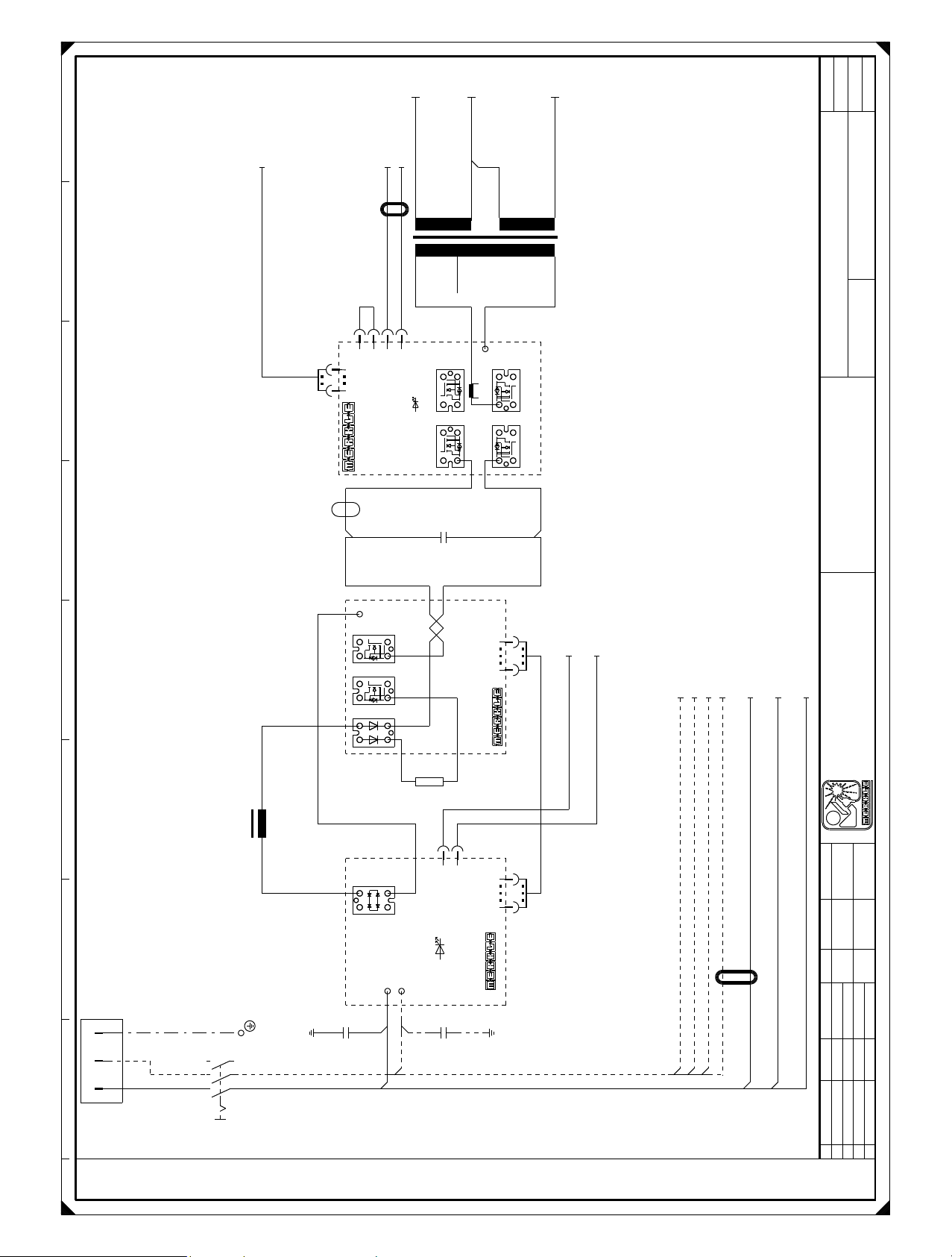
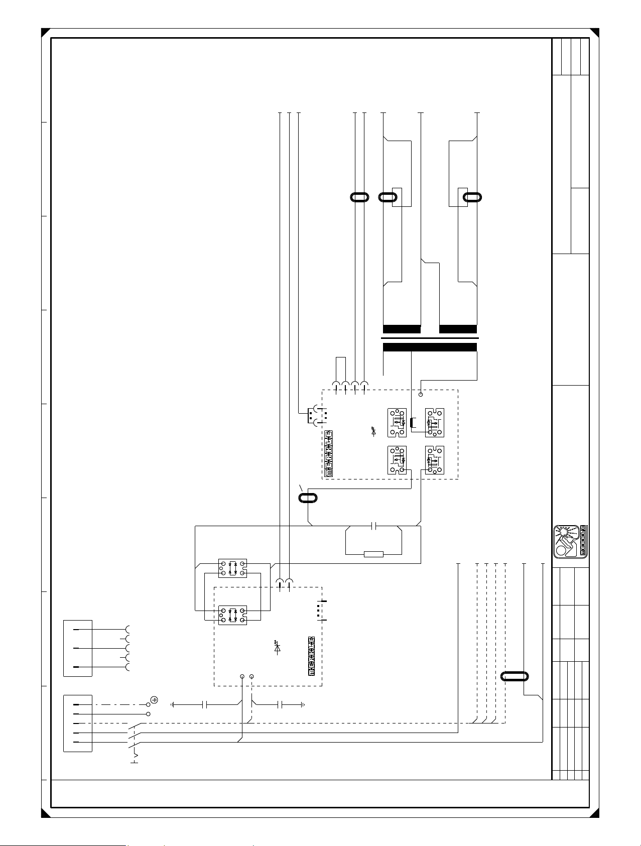
10. Wiring diagram LogiTIG 200/240 AC/DC
3/2.1
2/2.1
1/2.1
=
INV
+
1
Blatt
Bl.
4
+SQ-A3-X5/3.7
#447
Ferritring
ferrit ring
8 Windungen/
8 turns
+385V
+SQ-A4-X4:15/3.3
4 turns
Ferritring
ferrit ring
4 Windungen/
gr-sw
rt-sw
3
2
1
123
61
X3
X4
-A5
ME-I3-PSR-1.0
+SQ-A4-X4:16/3.3
3
2
45V45V
gr
310V
380V
4
4
12
4
-V7
3
Start
12
4
-V5
3
rt/2,5mm²
+
+
rt/2,5mm²
-C1
rt/2,5mm²
X1
2
3
4
3
4
1
0V
-V8
1 2
4x XFN44N50
-V6
1 2
bl/2,5mm²
bl/2,5mm²
bl/2,5mm²
-T1
Zeichnungsnr.
Projektbez.
Auftragsnr.
LOGITIG 200 AC/DC
Schweißstromkreis
X7
-V4
1
2
4
3
XFN44N50
1
2
-V3
4
3
XFN44N50
-V2
24
15k
-R1
230VAC
1
1
gn
bl
2
2
X4
Pr.DC.OK
3 1
DSEI2x61-06C
rt
+
+
~
~
-V1
4
1
sw/2,5mm²
-
-
2 3
~
~
VB040-08N06
-A1
X1
X2
-L1
ME-I3-PG-1.1
Erdungs-
PE
N
L1
1 2 3 4 5 6 7 8
schraube
L1 L2 L3
T1 T2 T3
-C2
0,022uF0,022uF
sw
bl
230V/50-60Hz/PE
+SQ
-Q1
110
-A2
X6
ME-I3-PFC-1.2
110
X5
-C3
+SQ-A4-X1:2/3.2
or-sw
#447
sw sw
+SQ-A4-X1:1/3.2
or-ws
+SQ-A4-X1:6/3.2
+OP1-X6:2/3.1
+SQ-M1/3.1
+SQ-A3-X2:1/3.5
bl
bl
bl
bl
Ferritring 8 Wdg.
ferritring 8 turns
bl bl
+OP1-X6:5/3.1
+SQ-A4-X1:8/3.2
sw
+SQ-A3-X2:3/3.5
sw
bn
Merkle
Schweißanlagen-Technik GmbH
Industriestraße 3
D - 89359 Kötz
Telefon 08221 -915 - 0
Telefax 08221 - 32596
Name
Konrad
Datum
11.04.06
gez.
gepr.
Name
Datum
20.11.07
Änderung
c
dab
Plotdatum:
Vervielfältigung oder Weitergabe nur mit unserer schriftlichen Genehmigung gestattet

42V~42V~
T70
+SQ
-A7
T0
D0
ignition generator
Zündgerät SIG 8.71/
DB
#433
-
+SQ-A4-X3:1/3.2
+SQ-A3-X11:4/3.5
+SQ
-X1
sw-gn
rs
rt
bl
sw/2,5mm²
#490
+
+SQ-A9-X4:1/4.7
+SQ-A3-X9:1/3.6
+SQ
-X2
bl
bl
+SQ-A3-X9:4/3.6
+SQ-A3-X4/3.6
rt
Ferritring
ferrit ring
8 Windungen/
#447
101
8 turns
bl
bl
rt
4
3
2
1
123
4
X4
ME-I2-WS-1.0
X1
UETWR
over temp
2
Bl.
INV
=
+
Blatt
4
+SQ-A4-X4:1/3.3
+SQ-A4-X4:2/3.3
+SQ-A4-X4:3/3.3
+SQ-A4-X4:4/3.3
ws-sw
ws-bl
ws-bn
ws-rt
1234
4 3 2 1
+
-
16
rtrtgn
Zeichnungsnr.
Projektbez.
Auftragsnr.
LOGITIG 200 AC/DC
X3 X2
1
-Z1
-A13
NTC montiert bei V12
SW/2,5mm²
ws sw
-R9
#447
rt
X8
X12X6X13
116
X1
NTCNTC
-V13 -V14
-A14
50W
-R5
-R6
3R3
bl bl
50W
X10
E2E2
X2
3
4
432
2
2
C2/E1 C2/E1
2
bl
1
1
X9
X4
X3
X5
X7
X11
ME-I3-WE-2.0A
Offset
1
1
Imax
-R7
1K0
rt
E1E1E2 E2
C1 C1
G2 G2G1 G1
-R4
3R3
3R3
50W
Schweißstromkreis
bl bl
bl bl
Merkle
Schweißanlagen-Technik GmbH
Industriestraße 3
D - 89359 Kötz
Telefon 08221 -915 - 0
Telefax 08221 - 32596
Name
Konrad
+SQ
2 Wdg.
2 turns
rt
+SQ-A9-X4:3/4.7
-L3
+SQ
sw/2,5mm²
sw/2,5mm²
2
+SQ
-L2
-R2
6,8R
-A11
X2
-V9
X4 X3
2
1
+
43
2
1
DSEI 2x61-06C
~
~
1
1
2
X1
43
ME-I3-SG-1.1+
-V10
-R3
6,8R
-A12
X2
4 3
-V11
X4 X3
-
1
2
DSEI 2x61-06C
~
4 3
~
2
1
1
2
X1
1
2
ME-I3-SG-1.1-
-V12
sw
ws
verdrillt
gnrtgr
1 2 3 4 5 6 7 8
Datum
11.04.06
gez.
Name
Datum
gepr.
20.11.07
2/1.8
1/1.8
3/1.8
+SQ-A3-X6:3/3.7
+SQ-A3-X6:2/3.7
+SQ-A3-X6:1/3.7
+SQ-A3-X6:4/3.7
Änderung
c
dab
Plotdatum:
Vervielfältigung oder Weitergabe nur mit unserer schriftlichen Genehmigung gestattet

=
SQ
+
3
Blatt
Bl.
4
+INV-A13-X2:1/2.6
+INV-A13-X2:4/2.6
+INV-A13-X2:3/2.6
+INV-A13-X2:2/2.6
ws-rt
ws-bn
ws-bl
ws-sw
+SQ-Q1:T2/1.1
+SQ-Q1:T3/1.1
bn
bl
+SQ-A5:X4
+INV-A13-X1/2.6
+SQ-A5-X3:4
+SQ-A5-X3:3
gr
gr-sw
-A6
bn-ws
#447
#447
ME-T4-Typ-1.1
1
X1
gn
10
1
87654321 654321
+SQ-A8-X5/4.7
+INV-A14-X2:1/2.3
+INV-A14-X2:2/2.3
+INV-A14-X2:3/2.3
+INV-A14-X2:4/2.3
sw
ws
gr
4
3
2
ISrtID
ge
110
4
X6
123
X4 X5
1 10 1 6
WD
gn
WK
gn
+60V
WD
0-45V
45V
X2 X3
230-B
230-N
1 2 3 4 5 6 7 8 1 2 3 4 5 6
WK-Rel
Lüfter
230V-A
21VAC
6
X1
65432
rt
0/21VAC
21VAC
5
4
+SQ-A8-X1/4.3
#447
#447
134
X15
X7
I>0
rt
ME-T4IF-1.3
WP
Not-Aus
-A3
HF
ge
rt
Stoe
rt
gn
Start
0/21VAC
11VAC
0-11VAC
1
2
3
1
Gas
Uist
X8
NTC
NTC
TH
TH
X9
+
-
42V-a
Gas
HF
X12
+24V
GND
+5V
NTC montiert bei V3
123412344321
sw
1234 56
4 3 2 1 6 5 4 3 2 1
X11
4 3 2 1
4 3 2 1
sw
-R8
+INV-A14-X3:2/2.4
+INV-A14-X3:1/2.4
rt
-Y1
bn-gn
Zeichnungsnr.
Projektbez.
Auftragsnr.
LOGITIG 200 AC/DC
Steuerung
3
2
1
2345678
1
21V
230V
4A
-F1
X1
8
7
8765432
sw
bl
1 2 3 4 5 6 7 8
+SQ-Q1:T1/1.1
vio-ge
vio-sw
gn-ws
8
7
6
5
4
21V
21V
0V
2
3
4
5
6
gr
or-sw
or-ws
+SQ-A1-X4:2
+SQ-Q1:T3/1.1
gn-sw
12
11
10
9
9
10111213141516
21V
21V
24V
10V
1
2
1
X2X4X3
1
M
-M1
+SQ-A1-X4:1
13
11V
-F2
1A
432
16
15
14
22V
45V
-A4
342
rs
PE
+SQ-A7:42V/2.5
1
1
gr
sw
Erdungs-
schraube
+OP1
-X6
bl
2
1
+SQ-Q1:T3/1.1
+SQ-Q1:T1/1.1
gn
bn
sw
ws
6
5
4
3
connection for
Option:
vio
watercooling unit
Wasserkühlgerätanschluß/
bl-rt
bl-ws
ge-sw
ge-sw
vio
bn
sw-gn
+SQ-A7:42V/2.5
+SQ-A8-X4:4/4.6
+SQ-A8-X4:3/4.6
+SQ-A8-X4:2/4.6
Merkle
Schweißanlagen-Technik GmbH
Industriestraße 3
D - 89359 Kötz
Telefon 08221 -915 - 0
Telefax 08221 - 32596
Name
Konrad
ge-sw ge-sw
Datum
11.04.06
gez.
gepr.
Name
rtblgnwsor
Datum
20.11.07
Änderung
+SQ-A8-X4:1/4.6
Vervielfältigung oder Weitergabe nur mit unserer schriftlichen Genehmigung gestattet
c
dab
Plotdatum:

+SQ-X2/2.8
+SQ-L3/2.5
4
Bl.
E
A
S
or
oder/
=
SQ
+
Blatt
4
rt
bl
4
3
2
1
4
3
2
1
-A9
ABCDE
ME-BT-4.0
bl-gn
bl-ws
bn-gn
4
5
6
65432
bn-gn
ge-rt
ge-sw
5
5
vio
X2
3
bl-ws
7
6
7
6
bn-ws
1
2
bn-ws
bl-gn
TEDAC-PWM(+)
TEDAC-IN(-)
X
torch poti
Brennerpoti/
110
X5
-A8
X
X
torch
BT2
switch 2
torch
BT1
switch 1
X
Gas
ME-TIG-4.3
end
I
down
t
or with torch poti
torch with 2 button
oder mit Brennerpoti/
Brenner mit Doppeltaster
Zeichnungsnr.
Projektbez.
Auftragsnr.
LOGITIG 200 AC/DC
Slave
1
X11
10
Test
1
X9
10
Frontplatte
-X5
54321
8
8
X4
234 1
X1
1
ws
vio
4 3 2 1
10 turns
#446 10Wdg.
432187654321
sw
1 2 3 410
X3 X4
1 2 3 4 5 6 7 8
+24V-Bn
Pwok-Or
GND-Gn
+5V-Rt
GND
10k-Poti
Fern/Netz
1 2 3 4 5 6 7 8
ABC
S
E A
control
hand remote
Handfernregler/
X10
X2
10
987654321
4321 5 6 7 8 9
Pol-Sync In
Pol-Sync Out
Robot-Ext
GND-Syn
GND-Rob
GND-Pot
Leit2-Poti
Leit1
+5V-Poti
Poti-Box on
341
X1
Menü
1 2 3 4
t1 t2
I1 I2
up
t
start
t
16 1
gas
t
X8
X8
Merkle
Schweißanlagen-Technik GmbH
Industriestraße 3
D - 89359 Kötz
Telefon 08221 -915 - 0
Telefax 08221 - 32596
1 6
#447
Name
#447
rt
gn
orbnbn
ws-sw ws-sw
gr
sw
bn-ws
vio
bl-gn
bl-ws
bn-gn
H
G
F
E
D
C
B
A
D
H
+SQ-A3-X12:4/3.4
ABCDE
+SQ-A3-X15/3.7
+SQ-A3-X12:3/3.4
+SQ-A3-X12:2/3.4
+SQ-A3-X12:1/3.4
S
E A
control
foot remote
Fußfernregler/
FT
-X4
J
I
F
G
electrode TEDAC
Elektrode TEDAC/
+SQ-A3-X7/3.7
Konrad
Datum
11.04.06
gez.
Name
Datum
Änderung
gepr.
20.11.07
c
dab
Plotdatum:
Vervielfältigung oder Weitergabe nur mit unserer schriftlichen Genehmigung gestattet
+SQ-A4-X1:2/3.2
+SQ-A4-X1:1/3.2
+SQ-A3-X5/3.7
or-ws
or-sw
4 turns
Ferritring
ferrit ring
4 Windungen/
+SQ-A4-X4:16/3.3
+SQ-A4-X4:15/3.3
3/2.1
2/2.1
1/2.1
1
SQ
=
+
Blatt
Zeichnungsnr.
Bl.
4
rt/2,5mm²
#447
Ferritring
ferrit ring
8 Windungen/
gr-sw
rt-sw
3
2
1
123
61
X3
X4
8 turns
ME-I3-PSR-1.1C/240
+310V
gr
4
4
-A5
rt/4mm²
+
+
Ferritring
ferrit ring
3
45V45V
380V
12
4
-V7
3
Start
12
4
-V5
3
2
310V
X1
3
4
3
IXFN55N50
4
bl/4mm²
1 2
1 2
2
Ferritring
-V8
-V6
ferrit ring
1
0V
-T1
Projektbez.
Auftragsnr.
LOGITIG 240 AC/DC
Schweißstromkreis
Merkle
Schweißanlagen-Technik GmbH
Industriestraße 3
D - 89359 Kötz
Telefon 08221 -915 - 0
Telefax 08221 - 32596
PE
N
L1
low power adapter
Low Power Adapter/
PE
L3
1 2 3 4 5 6 7 8
N
L2L1
High Power Anschluß/
high power connection
32A
PE
L3
N
L2L1
L1 L2 L3
Erdungs-
schraube
T1 T2 T3
-Q1
-
2 3
~
-
-
2 3
~
~
-A1
X1
X2
230VAC
VBO40-08N06
2
1
1
2
X4
VBO40-08N06
gn
Pr.DC.OK
-V2
+
4
1
~
-V1
+
+
4
1
~
~
ME-I3-PG-1.1A/240
0,022uF0,022uF
4mm²
bl
sw
-C2
-C3
X5
-R1 -C1
15K
bl/2,5mm²
110
+SQ-A3-X2:3/3.5
bl
bn
+SQ-A4-X1:6/3.2
+OP1-X6:2/3.1
+SQ-M1/3.1
+SQ-A3-X2:1/3.5
bl
bl
bl
bl
sw sw
Ferritring 8 Wdg.
+OP1-X6:5/3.1
+SQ-A4-X1:8/3.2
Name
sw sw
Datum
Name
Datum
Änderung
sw
ferritring 8 turns
Konrad
25.10.05
gez.
gepr.
20.11.07
c
dab
Plotdatum:
Vervielfältigung oder Weitergabe nur mit unserer schriftlichen Genehmigung gestattet

42V~42V~
T70
+SQ
-A7
T0
D0
ignition generator
Zündgerät SIG 8.71/
DB
#433
-
+SQ-A4-X3:1/3.2
+SQ-A3-X11:4/3.5
+SQ
-X1
sw-gn
rs
rt
bl
sw/2,5mm²
#490
+
+SQ-A9-X4:1/4.7
+SQ-A3-X9:1/3.6
+SQ
-X2
bl
bl
+SQ-A3-X9:4/3.6
+SQ-A3-X4/3.6
rt
Ferritring
ferrit ring
8 Windungen/
#447
101
8 turns
bl
bl
rt
4
3
2
1
123
4
X4
ME-I2-WS-1.0
X1
UETWR
over temp
2
Bl.
INV
=
+
Blatt
4
+SQ-A4-X4:1/3.3
+SQ-A4-X4:2/3.3
+SQ-A4-X4:3/3.3
+SQ-A4-X4:4/3.3
ws-sw
ws-bl
ws-bn
ws-rt
1234
4 3 2 1
+
-
16
rtrtgn
Zeichnungsnr.
Projektbez.
Auftragsnr.
LOGITIG 240 AC/DC
X3 X2
1
+SQ
2 Wdg.
2 turns
rt
+SQ-A9-X4:3/4.7
-L3
+SQ
-Z1
-A13
SW/2,5mm²
NTC montiert bei V12
ws sw
-R9
#447
rt
X8
X12X6X13
116
X1
NTCNTC
-V13 -V14
-A14
50W
-R5
-R6
3R3
bl bl
50W
X10
E2E2
X2
3
4
432
2
2
C2/E1 C2/E1
2
bl
1
1
X9
X4
X3
X5
X7
X11
ME-I3-WE-2.0A
Offset
1
1
Imax
-R7
1K0
rt
E1E1E2 E2
C1 C1
G2 G2G1 G1
-R4
3R3
3R3
50W
Schweißstromkreis
bl bl
bl bl
Merkle
Schweißanlagen-Technik GmbH
Industriestraße 3
D - 89359 Kötz
Telefon 08221 -915 - 0
Telefax 08221 - 32596
Name
Konrad
sw/2,5mm²
sw/2,5mm²
2
+SQ
-L2
-R2
6,8R
-A11
X2
-V9
X4 X3
2
1
~
+
43
2
1
DSEI 2x101-06A
~
1
1
2
X1
43
ME-I3-SG-1.1+
-V10
-R3
6,8R
-A12
X2
4 3
-V11
X4 X3
-
1
2
DSEI 2x101-06A
~
4 3
~
2
1
1
2
X1
1
2
ME-I3-SG-1.1-
-V12
sw
ws
verdrillt
gnrtgr
1 2 3 4 5 6 7 8
Datum
25.10.05
gez.
Name
Datum
gepr.
20.11.07
2/1.8
1/1.8
3/1.8
+SQ-A3-X6:3/3.7
+SQ-A3-X6:2/3.7
+SQ-A3-X6:1/3.7
+SQ-A3-X6:4/3.7
Änderung
c
dab
Plotdatum:
Vervielfältigung oder Weitergabe nur mit unserer schriftlichen Genehmigung gestattet

=
SQ
+
3
Blatt
Bl.
4
+INV-A13-X2:1/2.6
+INV-A13-X2:4/2.6
+INV-A13-X2:3/2.6
+INV-A13-X2:2/2.6
ws-rt
ws-bn
ws-bl
ws-sw
+SQ-Q1:T2/1.1
+SQ-Q1:T3/1.1
bn
bl
+SQ-A5:X4/1.4
+INV-A13-X1/2.6
+SQ-A5-X3:4/1.5
+SQ-A5-X3:3/1.5
gr
gr-sw
-A6
bn-ws
#447
#447
ME-T4-Typ-1.1
1
X1
gn
10
1
87654321 654321
+SQ-A8-X5/4.7
+INV-A14-X2:1/2.3
+INV-A14-X2:2/2.3
+INV-A14-X2:3/2.3
+INV-A14-X2:4/2.3
sw
ws
gr
4
3
2
ISrtID
ge
110
4
X6
123
X4 X5
1 10 1 6
WD
gn
WK
gn
+60V
WD
0-45V
45V
X2 X3
230-B
230-N
1 2 3 4 5 6 7 8 1 2 3 4 5 6
WK-Rel
Lüfter
230V-A
21VAC
6
X1
65432
rt
0/21VAC
21VAC
5
4
+SQ-A8-X1/4.3
#447
#447
134
X15
X7
I>0
rt
ME-T4IF-1.3
WP
Not-Aus
-A3
HF
ge
rt
Stoe
rt
gn
Start
0/21VAC
11VAC
0-11VAC
1
2
3
1
Gas
Uist
X8
NTC
NTC
TH
TH
X9
+
-
42V-a
Gas
HF
X12
+24V
GND
+5V
NTC montiert bei V2
123412344321
sw
1234 56
4 3 2 1 6 5 4 3 2 1
X11
4 3 2 1
4 3 2 1
sw
-R8
+INV-A14-X3:2/2.4
+INV-A14-X3:1/2.4
rt
-Y1
bn-gn
Zeichnungsnr.
Projektbez.
Auftragsnr.
LOGITIG 240 AC/DC
Steuerung
3
2
1
2345678
1
21V
230V
4A
-F1
X1
8
7
8765432
sw
bl
1 2 3 4 5 6 7 8
+SQ-Q1:T1/1.1
vio-ge
vio-sw
gn-ws
8
7
6
5
4
21V
21V
0V
2
3
4
5
6
gr
or-sw
or-ws
+SQ-Q1:T3/1.1
+SQ-A1-X4:2/1.3
gn-sw
13
12
11
10
9
9
10111213141516
21V
21V
11V
24V
1
X2X4X3
1
-F2
10V
1A
1
2
432
M
-M1
+SQ-A1-X4:1/1.3
16
15
14
22V
45V
-A4
342
rs
PE
+SQ-A7:42V/2.5
1
1
gr
sw
Erdungs-
schraube
+OP1
-X6
bl
2
1
+SQ-Q1:T3/1.1
+SQ-Q1:T1/1.1
gn
bn
sw
ws
6
5
4
3
connection for
Option:
vio
watercooling unit
Wasserkühlgerätanschluß/
bl-rt
bl-ws
ge-sw
ge-sw
vio
bn
sw-gn
+SQ-A7:42V/2.5
+SQ-A8-X4:4/4.6
+SQ-A8-X4:3/4.6
+SQ-A8-X4:2/4.6
Merkle
Schweißanlagen-Technik GmbH
Industriestraße 3
D - 89359 Kötz
Telefon 08221 -915 - 0
Telefax 08221 - 32596
Name
Konrad
ge-sw ge-sw
Datum
25.10.05
gez.
gepr.
Name
rtblgnwsor
Datum
20.11.07
Änderung
+SQ-A8-X4:1/4.6
Vervielfältigung oder Weitergabe nur mit unserer schriftlichen Genehmigung gestattet
c
dab
Plotdatum:

+SQ-X2/2.8
+SQ-L3/2.5
4
Bl.
E
A
S
or
oder/
=
SQ
+
Blatt
4
rt
bl
4
3
2
1
4
3
2
1
-A9
ABCDE
ME-BT-4.0
bl-gn
bl-ws
bn-gn
4
5
6
65432
bn-gn
ge-rt
ge-sw
5
5
vio
X2
3
bl-ws
7
6
7
6
bn-ws
1
2
bn-ws
bl-gn
TEDAC-PWM(+)
TEDAC-IN(-)
X
torch poti
Brennerpoti/
110
X5
-A8
X
X
torch
BT2
switch 2
torch
BT1
switch 1
X
Gas
ME-TIG-4.3
end
I
down
t
or with torch poti
torch with 2 button
oder mit Brennerpoti/
Brenner mit Doppeltaster
Zeichnungsnr.
Projektbez.
Auftragsnr.
LOGITIG 240 AC/DC
Slave
1
X11
10
Test
1
X9
10
Frontplatte
-X5
54321
8
8
X4
234 1
X1
1
ws
vio
4 3 2 1
10 turns
#446 10Wdg.
432187654321
sw
1 2 3 410
X3 X4
1 2 3 4 5 6 7 8
+24V-Bn
Pwok-Or
GND-Gn
+5V-Rt
GND
10k-Poti
Fern/Netz
1 2 3 4 5 6 7 8
ABC
S
E A
control
hand remote
Handfernregler/
X10
X2
10
987654321
4321 5 6 7 8 9
Pol-Sync In
Pol-Sync Out
Robot-Ext
GND-Syn
GND-Rob
GND-Pot
Leit2-Poti
Leit1
+5V-Poti
Poti-Box on
341
X1
Menü
1 2 3 4
t1 t2
I1 I2
up
t
start
t
16 1
gas
t
X8
X8
Merkle
Schweißanlagen-Technik GmbH
Industriestraße 3
D - 89359 Kötz
Telefon 08221 -915 - 0
Telefax 08221 - 32596
1 6
#447
Name
#447
rt
gn
orbnbn
ws-sw ws-sw
gr
sw
bn-ws
vio
bl-gn
bl-ws
bn-gn
H
G
F
E
D
C
B
A
D
H
+SQ-A3-X12:4/3.4
ABCDE
+SQ-A3-X15/3.7
+SQ-A3-X12:3/3.4
+SQ-A3-X12:2/3.4
+SQ-A3-X12:1/3.4
S
E A
control
foot remote
Fußfernregler/
FT
-X4
J
I
F
G
electrode TEDAC
Elektrode TEDAC/
+SQ-A3-X7/3.7
Konrad
Datum
25.10.05
gez.
Name
Datum
Änderung
gepr.
20.11.07
c
dab
Plotdatum:
Vervielfältigung oder Weitergabe nur mit unserer schriftlichen Genehmigung gestattet

Notes:

1. Edition 2006 August 28th. 2006
Technical changes reserved
 Loading...