

MERKLE LogiTIG 200 AC/DC, LogiTIG 240 AC/DC, LogiTIG 180 DC, LogiTIG 240 DC User Manual
USER MANUAL
LogiTIG
240 AC/DC
200 AC/DC


Content
1 The LogiTIG 200 AC/DC and 240 AC/DC
1.1 Intended Purpose
1.2 Transport
1.3 Positioning in the work place
1.3.1 Positioning
1.3.2 Use in conjunction with a power generator
1.3.3 Extension Cables
1.4 Start up Procedure
1.5 Illustration of the control panel and accessories attachments
1.6 Operation control in standard mode
2 TIG Welding
2.1 Process
2.2 Employment of the Process
2.3 Connection to the Mains
2.4 Joint preparation
2.5 Gas nozzle and welding current
2.6 TIG mode (standard operation)
2.6.1 Setting the welding current
2.6.2 TIG welding application
2.7 TIG Operation in standard mode
2.7.1 The DC welding mode
2.7.2 Alternating current (AC) welding mode
3 Electrode Welding (MMA Welding)
3.1 Process
3.2 MMA Preparation
3.3 Operation procedure
3.3.1 Display Details
3.3.2 Electrode Welding mode
3.4 Welding process
4 TIG – Expert Mode
5 Set-up Menu
6 Parameter adjustment range
7 Trouble shooting
8 Servicing
9 TIG hand welding torch – and spare parts

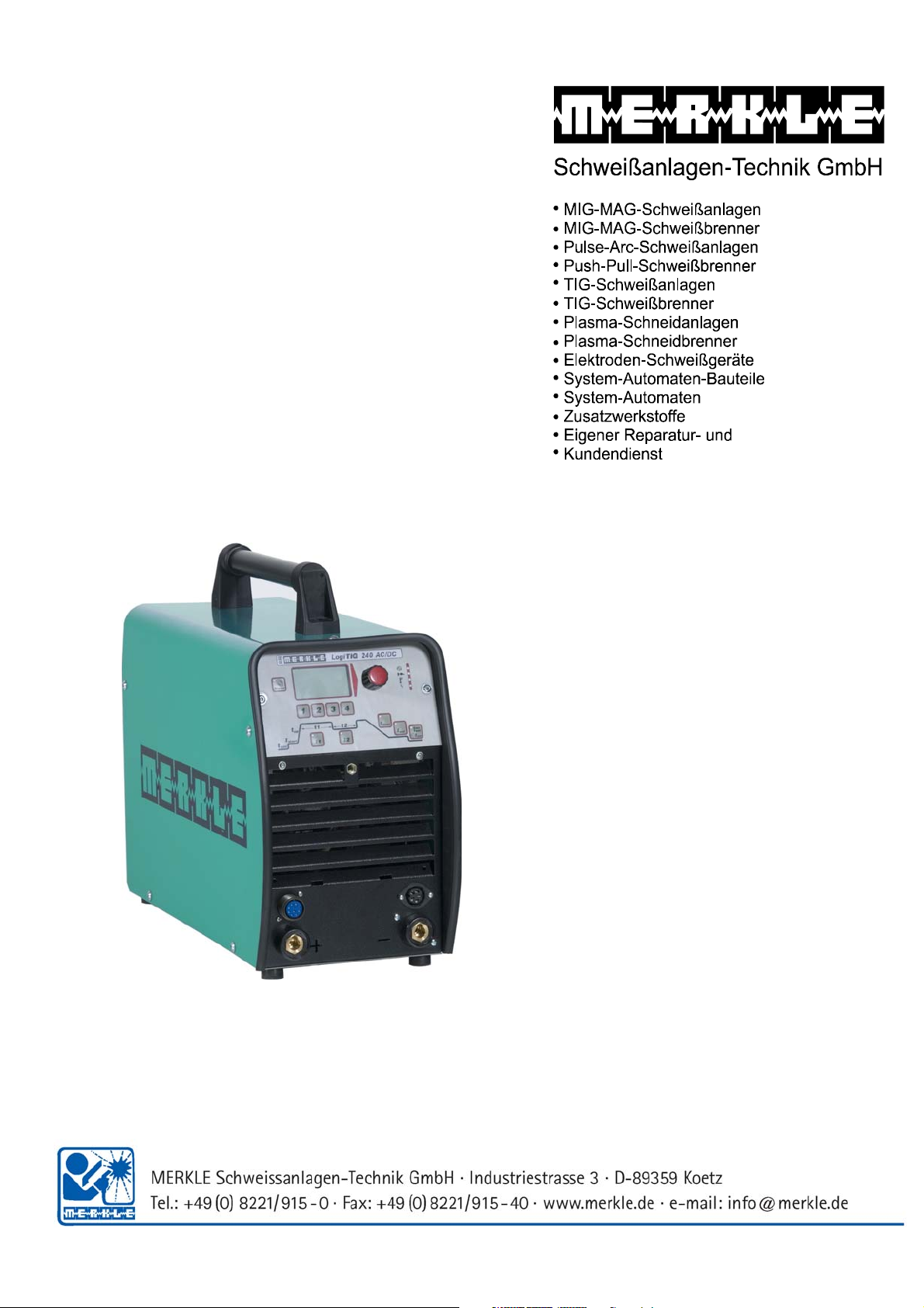
1. The LogiTIG 200 AC/DC and 240 AC/DC
The LogiTIG 200 AC/DC and the 240 AC/DC and are equipped with top of the line inverter
technology, they are designed to carry out the TIG and MMA welding processes in both AC and DC
current.
The welding machine is universally employable.
This series of machines lends itself well to on sight welding work. This is thanks high level of
mobility due to its extremely compact (space saving) design and reduced weight characteristics,
this coupled with the fact that it can also be run on a single phase 230V system (180A max)
1.1 Intended Purpose
This welding equipment it designed for the following processes
• MMA welding
• TIG welding with a shielding gas
All other processes undertaken with this machine are strongly ill advised and should not be
practised.
1.2 Transport
Before transporting this machine disconnect the gas line between the gas bottle and the welding
machine. During the transport make sure that the machine is secured in case of an accident.
DANGER:
• The gas bottle must be removed for the purpose of transportation.
• If not removed there is a danger of injury through falling gas bottles.
• DANGER OF EXPLOSION
1.3 Positioning in the work place
The machine should be placed in dry ambient areas and is designed only to be used in covered
protected environment.
Note:
• Never weld in open areas in the rain.
• Always check the proposed area for EMV activity
Should there be any disturbances then these must be eliminated before any
welding can take place.
• Danger is also present through electrically conductive components
• Isolation matting should be available for the protection of the operator from electric
shocks
1.3.1. Positioning
Attention
Cooling fans are employed in this machine to cool the power unit, therefore it is imperative that:
• Fresh air is allowed easy access to entry point (front) of the machine and the exiting air is
also free of any constricting obstacles.
• There should be an all round free space of approx. 80cm around the machine.
• In workshops with a high dust concentration an air filter should be employed on the
machine (optional extra).
• The machine should be placed on firm even ground.

• Ensure that the machine entry temperature is between -10 and +40°C
• Care should be taken to ensure that the rooms humidity is correct (up to 50% at 40°C and
90% at 20°C).
• The surrounding environment should be where possible free of excessive dust, acid and
corrosive gases.
• By higher concentrations of the above an air filter must be employed.
1.3.2. Use in conjunction with a power generator
• The power output of the generator should be at least 10% higher than the power intake of
the welding machine.
• The output voltage of the generator must also have a regulated open circuit voltage.
Switching on
First start the power generator and then switch on the welding machine.
Switching off
First switch off the welding machine and then the power generator.
By not adhering to the above advice YOU take the risk of damaging the machine through power
spikes.
1.3.3 Extension cables
Cautionary measures in the use of extension cables:
• The cable should be in a good and safe condition.
• The cable should always be fully removed from the cable drum.
• The maximum cable length should not exceed the conductor cross section value.
When these rules are not adhered to there is a real risk of overheating.
1.4 Start up Procedure
During the start-up process information about your machine is displayed on the Multi-Functional
display. You can according to the machine version various settings can be carried out.
• Start Process
• Turn the main power switch to position “I”.
• The software will be loaded and the Multi-Functional display (MFD) will show the
following information:
- Display version
- Machine version
- The last selected welding program
• During the start up process no setting changes can be made!
In the factory delivered condition the welding unit is set in “standard mode”. In this condition the
basic welding parameters are available. The operation is also simple. Should you require more
functions than are presently available then the machine can be switched to an “expert Mode”. The
procedure for this is explained in “Set-up menu” (chapter 7)

Special functions
• Resetting to factory settings (see Chapter 8)
Reset process explanation
• Colour adjustment of the MFD panel:
Select set-up menu
Press button I
1
The display panel background and script colour can be changed, i.e. black
/white to white/black
• Actual Welding Parameter will show all welding conditions one after the other
Press buttons I
and I2 together for 2 seconds.
1
• HIGH CURRENT / BIPOWER Technology (only LogiTIG 240 DC)
According to the power supply the maximum output available:
• Mains connection to 3 Ph 400 V-N-PE (32A):
TIG welding current up to 240A
MMA welding up to 200A
• With adapter 400/230V (16A)
TIG welding current up to 180A
MMA welding current up to 160A limited
• Duty Cycle (dc)
The Duty Cycle measurement is carried out according to EN 60974-1 / VDE 0544 in 10
Minute working cycles.
This has a value of 60% dc:
After a 6 minute welding period there must follow a 4 minute cooling phase.
The performance parts are Temperature controlled against overheating, after they have
switched off they will automatically re-activate when the temperature drops.
These values apply to working temperatures up to 40 °C and a maximum height above sea
of 1000m NN. Higher temperatures, attached air filters and higher altitudes will affect the
duty cycle values.
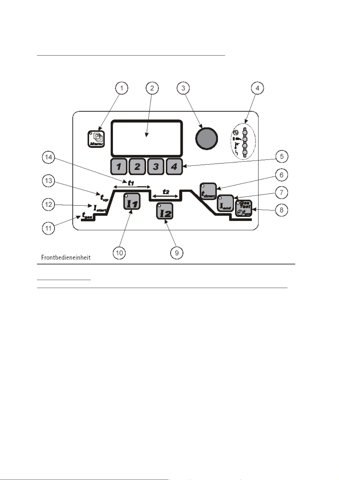
1.5 Illustration of the control panel and accessories attachments
Front panel controls
Position Sign Function___________________________________
1 Menu button button for Menu Functions (only in expert mode)
2 Display Panel shows Welding parameters
3 Incremental potentiometer endless rotary control for the setting of parameters
4 Status Display machine status and Warning indicators
5 Buttons 1-4 function buttons, module and menu functions
6 t
7 I
parameter buttons for setting of the down slope time
down
parameter button for setting the end current
end
8 Gas Test button for Gas test
9 I
10 I
11 t
12 I
13 t
14 t
parameter button for setting the 2nd welding current
2
parameter button for setting the 1st welding current
1
parameter button for setting the pre-gas flow time
gas
parameter button for setting the start current
start
up
and t2 parameter button for setting the I1and I2 current times
1
parameter button for setting the upslope time
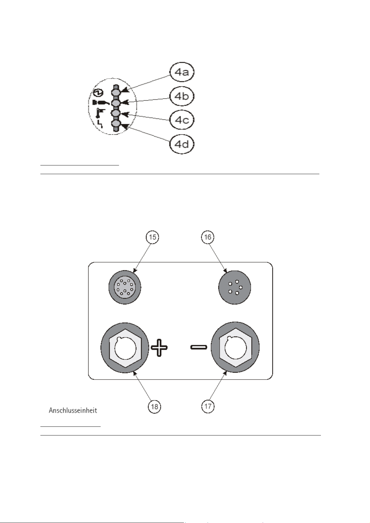
LED status/warning display
Position Sign Function _________________________________
4a Machine status display shows the machine has no-load current at the Poles
4b Network connection shows that the machine is switched on
4c Warning light temperature shows that the machine is overheating
4d Defect warning light shows that the machine has a defect
Connection adapters
Position Sign Function ____________________________
15 control cable remote control
16 control cable torch control
17 - Pole Busch TCG connection: combined Gas, TIG current and
MMA electrode holder
18 + Pole Busch Earth cable and MMA electrode holder connection
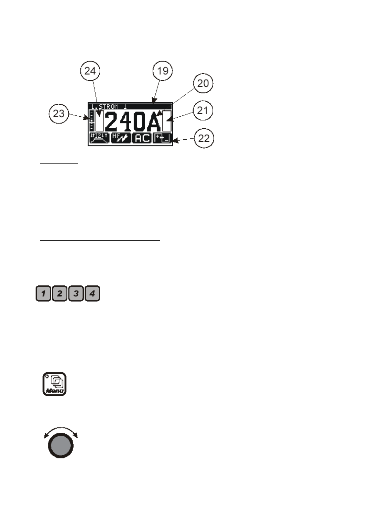
Display panel
Position Sign Function ____________________________
19 text field shows the parameter mode
20 parameter displays shows the actual parameter value selected
21 flag display field right shows the activated flags
22 pictogram line shows the selectable menus/modus functions
23 AC – balance scale graphic display for the AC balance value
24 flag display field left shows the activated flags
1.6 operation control in standard mode
The following diagrams clarify the function and pictogram in the display panel when used in the
standard mode of the welding unit.
Control button illustrations to be imported from the original document
Function buttons F1, F2, F3, and F4 for:
• Selection of the mode in connection with the pictogram on the
display, through the repeated use of the buttons.
• Selection of the parameters according to the pictogram in the
display and the adjustment of the values using the incremental
switch.
Menu button (in standard mode inaccessible)
• button for selection of the menu function
Incremental potentiometer
• continuous potentiometer without rotary limiter
• adjustment of the value of the selected parameter

Parameter button (PB) for the direct adjustment of the main welding
current I
. Integrated into the button is an LED.
1
• The LED button lights up:
When the current I
When the current I
is being adjusted
1
is active in the welding process
1
• If the main welding current I
welding current I
will adjust itself proportionately.
2
is adjusted, at the same time the
1
Parameter button (PB) for the adjustment of the welding current I2.
Integrated into the button is an LED.
• The LED button lights up:
When current I
is being adjusted
2
When the current I2 is active in the welding process
Should the I
welding current I
• The welding current I
current be altered, it will have no effect on the main
2
.
1
is only available in the following processes
2
Slow pulsing
Quick pulsing
4-stroke with current I
2
PB for the selection of the down slope t
is an LED.
• The down slope time of the welding current I
activated I
• Welding process with 2 welding currents I
• The function is active in:
PB for the selection of the end current I
is an LED.
• In the selected time the active welding current will be reduced until it
reaches the I
. Integrated into the button
down
until the end current is
1
end
and I2:
1
Both welding currents near themselves in the selected
time of the end current I
end
Pulse-setting
Stroke-modus
. Integrated into the button
end
current value.
end

PB “Gas-test”. Integrated into the button is an LED.
Warning light indicators
Setting the gas post flow
• Press button once
LED in button will light up
Post gas time can be set using the incremental parameter
Selecting the gas test function
• Press the button twice
LED in button will blink
The gas valve will open
The timer will run backwards
The gas valve will be closed automatically on reaching
zero
The gas valve can be manually closed by pressing the
button once more
After the completion of the gas test
The LED in the button will stay lit
Then the gas post flow can be set using the
incremental potentiometer
(as described in “gas post flow”)
Displaying the gas post flow function
• After the welding process has ended
The LED button will blink
The gas post flow will continue for the selected time
• Automatic purging of the gas line will follow:
When switching from MMA mode to TIG mode, when the
electrode is used.
During the running up of the welding unit whilst in TIG
mode.
Welding unit status indicator
• LED is lit
No load current is at the connecter bushes

Network connection status indicator
• LED lights up when:
The welding unit is connected to a mains adapter
The mains switch is switched on
Warning light – overheating of the power components
LED will blink when:
• The working temperature is 5°C before its critical limit is reached
• Advance warning that the welding process will be automatically
interrupted
LED is constantly lit
• Overheating temperature has been reached
• Before the welding process:
No welding process will be available until the unit has
cooled to a normal working temperature
• During the TIG welding process:
In 2-stroke and 4-stroke mode the welding current will be
reduced until it reaches the end currant. The welding
process will only be interrupted when the end current is
reached
With a foot control and an automated or robot unit the
program will be interrupted without the down slope
process being activated
Remote controls: if one of the following is in use: torch
trigger or foot control, the display panel will show the
following defect message, “release trigger”
• During the MMA welding process :
The welding process will be immediately interrupted
Defect warning light
This LED illuminates when there is a defect in the machine:
• Before the welding process has begun
No welding process possible
• During the TIG and MMA welding process
Welding process will be immediately interrupted
Warning lights and fault messages in the display unit
• “Release the trigger”
One of the following control elements is in use
Torch trigger, foot switch or control contact
• “Water pressure failure”

Flag Symbol
HOLD flag after the end of a welding process.
• The flag symbol shows the user that the welding parameters used
have been saved.
• The storage of the information is transient,
After an interruption the welding process will re-begin
with the same parameters.
Every parameter changed wipes the previously stored
parameter from the parameter settings.
The recalling of the previous weld settings through the
machine is then not possible.
• TIG welding parameters
The chosen parameters of the last used cycle before the
Down slope T
will be saved by the machines memory.
down
AC – Balance Scale
(The display is visible in conjunction with the TIG Modus function
“AC – Balance Amplitude”)
• The display is only visible in AC modus
• The vertical display represents the percentual share of the
positive half wave during the complete welding process (in
time).
• Indicator is positioned in the middle.
The positive and negative share of the wave is
identical.
• The indicator is positioned in the upper half of the scale
The positive half wave is larger than the negative half
wave
• Indicator in the lower half of the scale
The negative half wave is larger than the positive half
wave.
• One Pixel in the Horizontal translates to an adjustment of 3%.

2. TIG Welding
TIG Stands for Tungsten-inert-gas welding.
2.1 Process
A non consumable electrode made of tungsten or a tungsten alloy produces a welding arc. The
welding arc burns between the electrode and the work piece and is protected by an inert shielding
gas. The electrode and the molten pool are protected from the oxidising effects of the oxygen.
The inert gases used for this process are Argon; sometimes Helium or a mixture gas containing
both components can also be used.
The filler material is manually fed into the weld pool for manual welding process and mechanically
in the case of cold wire feed units.
2.2 Employment of the Process
The TIG process can be found employed joining foil and thin sheet together between 0.3 – 4.0mm
in one run, it is also used to join thicker pieces of material together (up to 12mm) when it can be
simultaneously welded from both sides. Thicker material would only be joined using the TIG
process when special technical demands dictate that TIG is the only process permit-able.
The TIG process produces a very high quality weld bead. The process therefore lends itself to
automatic welding as the process is easily controllable. In conjunction with special weld
preparations the process can be used on thicker materials for carrying out the root run. The
remainder fill and capping runs would be carried out using the MIG/MAG and Pulse-arc process.
2.3 Connection to the Mains
Mains connector
• Make sure that the machines main switch is in the “0” position
• The male connector is securely plugged into the correct mains current
Torch and hose assembly
• Combination connector (TGC-connector) must be connected to the minus pole (17)
connector.
• Turn the connector clockwise through 180
• The control socket should be connected plugged into socket 16 and secured using by
turning the twist connector until secure.
Earth return lead
• The earth return lead should be connected to the plus pole connector and turned
through 180º to secure.
• The earth clamp should then be secured to the work piece.
Gas bottle connection
• Lay the correct spanner for connecting the regulator within easy reach of the bottle.
• Remove the protective valve cap from the bottle.
• The gas valve should then be purged to remove all foreign bodies from the valve area.
• The gas pressure gauge connection should then be checked to see that it is also clean.
• The gas pressure gauge can now be screwed to the bottle and secured tightly using the
spanner. Make sure that the gasket ring in the valve nut is securely in place and not
damaged in any way. If so then replace with a new one.
º
to ensure secure connection.

2.4 Joint preparation
The TIG process requires that the weld joint is dry and free from grease and oil or any other sort of
dirt contamination. The necessary edge preparation depends on the thickness and the position of
the weld along with the job itself. These conditions are standardized in DIN 8552, part 1.
2.5 Gas nozzle and welding current
During the welding process using a shielding gas it is essential that the weld pool is covered with
the Argon gas and therefore protected from the harmful effects of contamination (oxidization)
from normal air in the shielding gas area. To guarantee such welding conditions the following
parameters must be finely tuned:
• Gas Flow
• Gas nozzle size
• Required welding current
Extreme care needs to be taken to avoid gas turbulence as this phenomenon has the undesired
effect of allowing air into the protective gas mantle.
Using a standard gas nozzle does not always guarantee turbulence free welding. Using the so
called “Gas lens” a special nozzle is used to allow the gas to flow freely without any turbulence.
The gas lens concentrates the gas flow in such a way that it allows a greater gap between the
work piece and welding torch. This in turn allows the tungsten electrode to be fixed with a
protrusion of up to 10mm outside the gas nozzle. This then allows the easy access of corners and
other difficult to get to joints.
Through a longer protrusion of the weld electrode the dead spot becomes smaller and the view of
the weld pool is greatly improved. The “gas lens” also allows under the same current conditions a
much reduced gas consumption.
Using the TIG process the optimal setting of the welding current is especially important; the end of
the tungsten electrode must be equally burdened:
• Using a current too low for the tungsten electrode, the arc is not able to cover the
complete tip of the electrode and therefore wanders on the tip and is not stable which
in turn affects the weld process.
• Contrarily the overloading of the electrode causes it to melt, so that tungsten can be
transferred to the weld pool. The inclusion of Tungsten in the weld pool is a weld
defect that should be removed and redone.
2.6 TIG mode (standard operation)
In the following chapter you will learn about how to operate the machine in the standard mode.
At the end you will be able to use machine in the standard TIG process and also correctly set your
own welding conditions.
2.6.1 Setting the welding current
Before the start of the welding process
• Select the required welding current through the incremental potentiometer dial (3)
• This indicated value is 100% and is displayed on the display in Amperes.

During the welding process
The operator has several methods available to adjust the weld current.
• Through the incremental potentiometer (3)
• Using a remote control unit;
Torch potentiometer
Hand remote control
Foot remote control
The current value set using the incremental potentiometer automatically determines the end value
for the hand potentiometer. During the welding process the display shows the value of the
condition set using the remote control system.
A change through the use of the remote control varies the welding current between 0% and 100%
in reference to the incremental potentiometer selected welding current.
The display shows the ampere value of the welding current.
Welding current after interruption
• Interruption <5 s:
The last selected conditions (on the incremental potentiometer or remote control)
would be reselected
• Interruption >5 s:(forced interruption)
The welding current will return to the value last selected through the incremental
potentiometer.
2.6.2 TIG welding application
2-stroke operation
During the complete welding program the torch trigger must be kept pressed, after the release of
the trigger the selected down slope program is engaged, after that the selected gas post flow.
• Select the F1 button on the front panel
• Torch trigger press and hold
The torch will ignite
The welding process will start with welding current I
1
• Release the torch trigger
The down slope LED will light up (I
LED extinguishes)
1
After the down slope program has run the LED will be extinguished
The welding program is ended
The gas test LED will light up
The gas post flow will now activate
Gas test LED is extinguished, the post flow gas is ended
Note: During the ending of the welding process in the 2-stroke operation, the end current I
end
is
not activated.

4-stroke operation
With the pressing of the trigger the start current (I
(t
) is introduced as programmed until the welding current has reached the requested setting (I1).
up
If the torch trigger is then pressed again then the down slope (t
current (I
) is reached. Once the trigger is then released the arc is extinguished and the post flow
end
) is activated, after it is released the up slope
start
) is activated until the end
down
gas is activated.
4-Stroke operation with a secondary pulse welding current I
2
The trigger functions are the same as in the standard 4-stroke operation. The only difference
occurs during the welding process whereby the quick pressing of the trigger activates the
secondary pulse current I
current (I
).
1
, a repeated pressing of the trigger then returns the original welding
2
If the trigger is depressed for longer than 0.5 seconds then the welding current down slope is
activated and followed by the post gas flow.
Manual Pulsing
• Press The torch trigger(TT):
Arc is ignited
The process is started with welding current I
I
-LED on display panel will illuminate
1
1
• Press TT and release (<0,5 s):
Current I
I
LED on display panel will illuminate (I1 LED will be extinguished)
2
will be activated
2
• Press TT and release (< 0,5 s)
Current I
I
LED on display panel will be activated (I2 LED will be extinguished)
1
will be reactivated.
1
• TT press and Hold ( > 0,5 s)
The down slope LED t
After the t
End current (I
sequence has run the t
down
) LED is illuminated and the end current is active
end
will illuminate on the panel (I1 LED extinguished)
down
LED will extinguish
down
• Release the TT
End current LED is extinguished
Welding process will be ended
Gas post flow LED will be illuminated
Gas post flow will be ended
Gas post flow LED will be extinguished
Gas post flow LED will be extinguished, the cooling process is ended
2.7 TIG Operation in standard mode
2.7.1 the DC welding mode
With the TIG process mostly high alloyed steels are welded, generally speaking steel and copper
can be welded with DC (direct) current. To avoid a critical thermal loading of the electrode, the
welding torch should be connected to the Minus pole and the earth return lead to the plus pole of
the machine. The temperature on the minus pole is ca. 3600°C, the plus pole is ca. 4200°C.
 Loading...