

MERKLE INSQUARE W 300 DC, INSQUARE W 300 AC/DC, INSQUARE W 420 DC, INSQUARE W 600 AC/DC, INSQUARE W 420 AC/DC Operation Manuals
Operation Manual
TIG Welding Units model INSQUARE
W 300 /DC / W 420 /DC
W 300 AC/DC / W 420 AC/DC
W 600 AC/DC
MERKLE
Schweißanlagen-Technik GmbH
Industriestraße 3
D-89359 Kötz
Tel.: (08221) 915-0
Fax: (08221) 915-40
www.merkle.de

.

Content page
1st Security indications before introduction 3
2. Accident prevention regulations 3
2nd1 Safety instructions 3
3rd Duty cycle 5
4th Instructions to avoid interferences due to electromagnetic influences EMC 5
5. Technical Data: 7
5th1 TIG Welding Unit, model Insquare W 300 / 420 DC: 7
5th2 TIG Welding Unit, model Insquare W 300 / 420 AC-DC: 9
5th3 TIG Welding Unit, model Insquare W 600 AC-DC: 12
6. Set Up 14
6th1 Installation of the Machine 14
6th2 Main Supply 14
6th3 Welding Torch 14
6th4 Earth Lead (Work Cable) 14
6th5 Electrode holder 14
6th6 Transport 14
7. TIG-Welding Unit, model Insquare W 300 /420 / 600 15
7th1 Automatic safety switch off 15
8. Operation of the Unit 19
9. TIG welding 23
9th1 preparing-values at DC welding 23
9th2 preparing-values at AC welding 24
10. MMA stick electrode –welding 24
10th1 Standard values for the metal arc welding 25
11. Display 25
12. Trouble Shooting 26
13. Cleaning 27
14. Maintenance and Accident Prevention 27
15. Inspection 27
1

16. TIG hand welding torch - and spare parts 28
16th1 TIG Hand Welding Torch, Model TH 450 W, water cooled, 28
16th2 TIG Hand Welding Torch, Model TH 600 W, water cooled, 33
17. Spare parts and wiring diagram 37
17th1 Spare part list TIG Insquare W 300/420 DC 37
17th2 Wiring diagram INS 300-420 DC 38
17th3 Spare part list TIG Insquare W 300 AC/DC 43
17th4 Wiring diagram INS W 300 AC/DC 44
17th5 Spare part list TIG Insquare W 420 AC/DC 50
17th6 Wiring diagram INS W 420 AC/DC 51
17th7 Spare part list TIG Insquare W 600 AC/DC 57
17th8 Wiring diagram INS W 600 AC/DC 59
18. EU-Conformity Attestation INS 300-420 69
19. EU-Conformity Attestation INS 600 70
2

1st Security indications before introduction
The welding unit is built according to recognized standards. Safe works are nevertheless only
possible if you read the operating instructions and the safety regulations contained in it
entirely and obey strictly. Instruct yourselves by trained staff from us or contact our
appointed dealers.
2. Accident prevention regulations
The following accident prevention regulation is applied for welding with TIG - welding unit,
model INSQUARE W 300/420 DC, W 300/420 AC/DC and W600 AC/DC,
BGV D1 (earlier VBG 15) * Welding, cutting and allied processes.
A copy of this regulation should be readily accessible in every welding shop. The stipulations
of this regulation are to be observed in the interests of safe and correct welding operation.
* Available from the trade association responsible or
Carl Heymanns-Verlag, Luxemburger Strasse 449, 50939 Cologne.
2nd1 Safety instructions
This unit is manufactured according to the requirements and stipulations of EN 60974.1 /
VDE 0544 part 1. The accident prevention regulations “Welding, cutting and allied
processes”
BGV D1 (earlier VBG 15) of the trade association for precision engineering and electrical
engineering are as well valid.
1) In case of an accident, the welding unit must be disconnected from the mains
immediately.
2) If electrical contact voltages arise, switch off the unit immediately, disconnect it from
the mains and proceed to inspection by a qualified electrician or by our Service
Department.
3) Before opening the unit, disconnect it from the mains supply.
4) Repair work may only be carried out by a skilled electrician or by our Service
Department.
5) Before the unit is put to operation, check it visually, as well as the torch and all cables
and connectors regarding possible external damages.
6) Personal protective equipment in accordance with DIN EN 175, DIN EN 379 and
DIN EN 169.
During the work, the welder’s body must be completely protected against radiation
and burns by means of protective clothing and face protection. Long gloves, aprons
and welding shields with welding filters conforming to DIN EN 470-1 and BGR 189
must be worn. Synthetic clothing are excluded. Shoes must be closed, not opened (due
to spatters). If necessary, protective headwear must be worn (e.g. for overhead
welding). If cover glasses are used, these must be in accordance with the norms
specified above. As additional protection for the eyes against UV radiation, safety
goggles with side shields and corresponding face protection in accordance with
BGR 192 and BGI 553 must be worn.
Accident prevention regulation BGV D1 § 27 stipulates that it is the responsibility of
the employer to provide suitable personal protective equipment, while § 28 stipulates
that it is the responsibility of the insured to wear suitable clothing.
3

7) Protection when welding under increased electrical risks
Welding rectifiers and welding power sources which can optionally be used for either
direct or alternating current must be marked "S" in accordance with EN 60974-1 and
BGI 534.
Use insulating materials to protect you against contact with electrically conductive
parts and damp floors. Wear dry, undamaged work clothing, long gloves and footwear
with rubber soles. Ventilate rooms, install extraction systems if required, and wear
respiratory protective equipment if necessary (see Procedural instructions BGV D1
§ 27 and BGI 533, Section 5).
8) In order to prevent stray currents and the effects thereof (e.g. destruction of electrical
protective ground conductors), the welding return cable (workpiece cable) must be
connected directly to the workpiece to be welded or to the table (e.g. welding table,
grid-type welding table, workbench) supporting the workpiece (see BGV D1 § 20).
When installing the ground connection, assure that there is a good electrical contact
(remove rust, paint, etc.).
9) During welding pauses, the welding torch is to be laid down on an insulated surface or
hung up in such a way that it is not in contact with the workpiece and its support
connected to the welding power source (see § 20 BGV D1).
In the case of longer work pauses, the welding unit must be switched off and the gas
cylinder valve must be closed.
10) The shielding gas cylinder must always be protected against tumbling downing using a
safety chain.
11) Under no circumstances the unit may be put into operation while it is opened
(e.g. for repair work). Apart from the safety regulations, sufficient cooling of the
electrical components provided by the fan cannot be guaranteed.
12) In accordance with BGV D1 § 5, people in the vicinity of the arc must also be
informed of the hazards and protected against them. Safety partitions (“welding safety
curtains”) must be erected in accordance with DIN EN 1598.
a. No welding work may be carried out on containers in which gases, fuels, mineral oils
or similar substances have been stored Öeven if they have been empty for a long
timeÕ (risk of explosion). See § 31 of accident prevention regulation BGV D1.
14) Welds which will be subjected to high loads and which need to meet specific safety
requirements may only be carried out by specially trained and qualified welders.
15) Do never bring the torch close to your face.
16) In areas at particularly high risk of fire, the welder must obtain a welding permit and
have this on his person throughout the duration of the welding work. On completion of
welding, a fire-guard must be delegated to ensure fire protection.
17) Ventilation measures must be applied in accordance with BGI 553, Section 9.
18) The hazard to eyesight must be indicated by means of a sign at the work site
"CAUTION! Do not look into the arc!".
4

3rd Duty cycle
The duty cylce measurings have been carried out in accordance with
EN 60974-1 / VDE 0544 part 1 (10 min working period).
60% duty cycle means:
After a 6 min. welding period a 4 min welding pause must be respected. The electrical
components are thermally protected against overheating.
4th Instructions to avoid interferences due to electromagnetic influences
EMC
The welding unit has been manufactured in accordance with the requirements of guideline
EN 60974-10 regarding electromagnetic compatibility. It is nonetheless the responsibility of
the user to ensure that the welding equipment is installed and operated in accordance with the
manufacturer’s instructions. If electromagnetic interference is detected, it is the responsibility
of the user of the welding equipment to find a solution with the technical assistance of the
manufacturer. In some cases, it may be sufficient simply to ground the welding current
circuit. In other cases, it may be necessary to build a complete shield for the welding power
source and workpiece using the input filters. In all cases, electromagnetic interference must be
reduced to avoid any possible malfunctions.
Note:
For safety reasons, the welding current circuit may or may not be grounded. No
modifications may be made to the grounding without the approval of an expert who is able to
determine whether the changes might increase the risk of accidents, e.g. by allowing parallel
welding current return paths which could destroy the ground conductors of other equipment.
Further instructions are contained in TEC 974-XX "Arc welding equipment – installation and
use".
a) Evaluation of the installation site
Before installing the welding equipment, the user must evaluate potential
electromagnetic problems in the vicinity. The following must be taken into
consideration:
¾ Other power cables, control cables, signal and telecommunication cables above, below
and next to the welding equipment
¾ Radio and television transmitters and receivers
¾ Computers and other control devices
¾ The health of people in the vicinity, e.g. use of heart pacemaker and hearing aids
¾ Calibration and measuring equipment
¾ Interference immunity of other devices in the vicinity. The user must ensure the
electromagnetic compatibility of other devices used in the vicinity. This may require
additional safety measures.
b) Procedures to reduce emitted interference
1) Mains supply
Welding equipment is to be connected to the mains in compliance with the
recommendations of the manufacturer. If interference occurs, it may be necessary to
take additional precautions, e.g. filters for the mains connection. Make sure that the
power cable of welding equipment is installed in a fixed position shielded by means of
a metal conduit or similar. The entire length of the shield must be electrically
connected. The shield must be connected to the welding power source in the way to
obtain a good electrical contact between the metal conduit and the housing of the
welding unit.
5

2) Maintenance of the welding equipment
Welding equipment must be maintained regularly in accordance with the
recommendations of the manufacturer. All access and service doors and covers must
be closed and fastened securely when the welding equipment is in operation. No
modifications whatsoever may be made to welding equipment with the exception of
modifications and adjustments specified in the manufacturer’s operating instructions.
3) Welding cables
Welding cables should be kept as short as possible and routed close together on or
near the floor.
4) Equipotential bonding
It is advisable to interconnect all metallic parts in and next to the welding equipment.
Metallic parts connected to the workpiece can, however, increase the risk of the
welder receiving an electric shock by touching these metallic parts and the electrode
simultaneously. The welder must be electrically insulated against all these connected
metallic parts.
5) Grounding the workpiece
If the workpiece is not connected to the ground for electrical safety reasons, or due to
the size and position of the workpiece, e.g. steel structure or outer wall of a ship,
grounding the workpiece may in some cases, but not all, reduce emitted interference. It
must be ensured that grounding the workpiece will not increase the risk of accidents
for the user and cannot cause the destruction of other electrical equipment. If
necessary, the grounding of the workpiece must be carried out by means of a direct
connection to the workpiece. In countries where a direct connection is prohibited, the
connection must be made by means of suitable reactors, selected in accordance with
national regulations.
6) Shielding
Selective shielding of other cables and devices in the vicinity can reduce interference
problems. For special applications, it may be worth considering shielding the entire
welding system.
6

5. Technical Data:
5th1 TIG Welding Unit, model Insquare W 300 / 420 DC:
Insquare W 300 DC Insquare 420 DC
Primary:
Power supply: 3 x 400 V 3 x 400 V
Frequency: 50 (60) Hz 50 (60) Hz
cos phi: 0.95 0.95
TIG DC operation:
Open circuit voltage: 80 V 80V
Welding voltage: 10 - 22.8 V 10-26,8 V
Welding current: 5-320 A 5-420 A
Duty cycle 60 %: 320 A (10 min.) 420 (10 min.)
Duty cycle 80 %: 300 A (10 min.) 400 (10 min.)
Duty cycle 100 %: 260 A (40°C) 310 A (40°C)
Prim. cont. power: 9.5 kVA 12 kVA
Prim. cont. current: 13.7 A 17,4 A
Prim. max. current: 19 A 28 A
MMA/stick electrode operation:
Stick electrodes: 1.5-6 mm 1.5-6 mm
Open circuit voltage: 80 V 80 V
Welding voltage: 20 - 32.8 V 20-36,8 V
Welding current: 5-320 A 5-420 A
Duty cycle 50 % 420 A (10 min.)
Duty cycle 60 %: 320 A (10 min.) 400 A (10 min.)
Duty cycle 80 %: 300 A (10 min.)
Duty cycle 100 %: 260 A (40°C) 300 A (40°C)
Prim. cont. power: 13.1 kVA 14,5 kVA
Prim. cont. current: 19 A 21 A
Prim. max. current: 22 A 34 A
Protection class: IP 21
Insulation class: H
Cooling: AF
Main switch: 3-phase
Welding modes: TIG DC,
MMA/stick electrode
Selector 1: current 1, time 1,
upslope and downslope time,
start current, final current,
spot welding time,
gas pre- and post-flow time
Selector 2: current 2, time 2,
(for pulsation),
hotstart time a. current,
arc force, stick electrode mm ∅,
display voltage
Adjusting: 2 rotary switches
for slectors 1 and 2
7

Digital displays: 2 displays with pre-indication
and hold function for current,
voltage, time, frequency
Timer functions: OFF, quick and slow pulsation,
spot welding time
Ignition: OFF, high frequency,
lift arc
Energy control: at the machine, at the torch,
hand remote control, foot pedal
Operation modes: 2-stroke, 4-stroke, 4-stroke
with 2 currents, gas check,
test, programming
Program storage: 20 programs
Gas pre-flow time: 0-3 s
Gas post-flow time: 0-25 s
Up slope time: 0-2 s
Down slope time: 0-20 s
Spot welding time: 0.1-2.5 s
Pulsation slow: 10 ms-2.5 s
Pulsation fast: 50 Hz-5 kHz
Hotstart time: 0-1.5 s
Hotstart current: 10-200 %
Arc force: 100-250 %
Button: program selection
LEDs: mains ON, temperature
protection, failure,
hold function,
start current, up slope, down
slope, current 1 + 2, final curr.
Power source: IGBT inverter
Ignition: HF generator or lift arc
Norm: EN 60974-1 "S" / CE
Torch connection: Euro connector
with 5-pole plug
Torch cooling: integrated water cooling system
Socket 50 mm²: earth lead
Socket 50 mm²: electode welding cable
Mains supply cable: 4 x 4 mm², 5 m long
Gas hose: 2 m long
Weight: 115 kg (W 300 DC) 125 kg (W 420 DC)
Dimensions L x W x H: 910 x 600 x 910 mm
incl. gas bottle holder
Gas bottle holder: 10 - 20 - 50 l cylinders
Lifting eyes: 4 pieces (option)
Standard accessories:
Earth lead 50 mm², 4 m long 022.1.0402
with plug and earth clamp (W 300 DC)
Earth lead 70 mm², 4 m long 022.1.0408
with plug and earth clamp (W 420 DC)
Regulator argon/CO2, single stage 012.0.0300
8

5th2 TIG Welding Unit, model Insquare W 300 / 420 AC-DC:
Insquare W 300 AC-DC Insquare 420 AC-DC
Primary:
Power supply: 3 x 400 V 3 x 400 V
Frequency: 50 (60) Hz 50 (60) Hz
cos phi: 0.95 0.95
TIG DC operation:
Open circuit voltage: 80 V 80 V
Welding voltage: 10 - 22.8 V 10-26,8 V
Welding current: 5-320 A 5-420 A
Duty cycle 60 %: 320 A (10 min.) 420 (10 min.)
Duty cycle 80 %: 300 A (10 min.) 400 (10 min.)
Duty cycle 100 %: 260 A (40°C) 310 A (40°C)
Prim. cont. power: 9.5 kVA 12 kVA
Prim. cont. current: 13.7 A 17,4 A
Prim. max. current: 19 A 28 A
TIG AC operation:
Open circuit voltage: 80 V 80V
Welding voltage: 10 - 22.8 V 10-26,8 V
Welding current: 5-320 A 5-420 A
Duty cycle 60 %: 320 A (10 min.) 420 (10 min.)
Duty cycle 80 %: 300 A (10 min.)
Duty cycle 100 %: 260 A (40°C) 310 A (40°C)
Prim. cont. power: 9.5 kVA 12 kVA
Prim. cont. current: 13.7 A 17,4 A
Prim. max. current: 19 A 28 A
MMA/stick electrode operation:
Stick electrodes: 1.5-6 mm 1.5-6 mm
Open circuit voltage: 80 V 80 V
Welding voltage: 20 - 32.8 V 20-36,8 V
Welding current: 5-320 A 5-420 A
Duty cycle 50 % 420 A (10 min.)
Duty cycle 60 %: 320 A (10 min.) 400 A (10 min.)
Duty cycle 80 %: 300 A (10 min.)
Duty cycle 100 %: 260 A (40°C) 300 A (40°C)
Prim. cont. power: 13.1 kVA 14,5 kVA
Prim. cont. current: 19 A 21 A
Prim. max. current: 22 A 34 A
Protection class: IP 21
Insulation class: H
Cooling: AF
Main switch: 3-phase
Welding modes: TIG DC (-), TIG DC (+),
TIG DC (-) w. start puls (+),
TIG AC "noise reduced",
9

TIG AC "square arc",
TIG AC "balanced TIG",
MMA/stick electrode (-),
MMA/stick electrode (+),
MMA/stick electrode sinusodial,
MMA/stick electrode square arc
Selector 1: current 1, time 1,
upslope and downslope time,
start current, final current,
ignition impulse, spot w. time,
gas pre- and post-flow time
Selector 2: current 2, time 2,
(for pulsation),
AC balance, AC frequency,
hotstart time a. current,
arc force, stick electrode mm ∅,
display voltage
Adjusting: 2 rotary switches
for slectors 1 and 2
Digital displays: 2 displays with pre-indication
and hold function for current,
voltage, time, frequency
Timer functions: OFF, quick and slow pulsation,
spot welding time
Ignition: OFF, high frequency,
lift arc
Energy control: at the machine, at the torch,
hand remote control, foot pedal
Operation modes: 2-stroke, 4-stroke, 4-stroke
with 2 currents, gas check,
test, programming
Program storage: 20 programs
AC frequency: 50-200 Hz
AC balance: 9-91 %
Gas pre-flow time: 0-3 s
Gas post-flow time: 0-25 s
Up slope time: 0-2 s
Down slope time: 0-20 s
Ignition impulse: 0-100 ms
Spot welding time: 0.1-2.5 s
Pulsation slow: 10 ms-2.5 s
Pulsation fast: 50 Hz-5 kHz
Hotstart time: 0-1.5 s
Hotstart current: 10-200 %
Arc force: 100-250 %
Button: test protection device
Button: program selection
LEDs: mains ON, temperature
protection, failure,
protection device, hold function,
start current, up slope, down
10

slope, current 1 + 2, final curr.
Power source: IGBT inverter
Ignition: HF generator or lift arc
Norm: EN 60974-1 "S" / CE
Torch connection: Euro connector
with 5-pole plug
Torch cooling: integrated water cooling system
Socket 50 mm²: earth lead
Socket 50 mm²: electode welding cable
Mains supply cable: 4 x 4 mm², 5 m long
Gas hose: 2 m long
Weight: 130 kg (W 300 DC) 140 kg (W 420 DC)
Dimensions L x W x H: 910 x 600 x 910 mm
incl. gas bottle holder
Gas bottle holder: 10 - 20 - 50 l cylinders
Lifting eyes: 4 pieces (option)
Standard accessories:
Earth lead 50 mm², 4 m long 022.1.0402
with plug and earth clamp (W 300 AC-DC)
Earth lead 70 mm², 4 m long 022.1.0408
with plug and earth clamp (W 420 AC-DC)
Regulator argon/CO2, single stage 012.0.0300
11

5th3 TIG Welding Unit, model Insquare W 600 AC-DC:
Primary:
Power supply: 3 x 400 V
Frequency: 50 (60) Hz
cos phi: 0.95
TIG DC operation:
Open circuit voltage: 80 V
Welding voltage: 10 - 34 V
Welding current: 20-600 A
Duty cycle 60 %: 600 A (10 min.)
Duty cycle 100 %: 500 A (40°C)
Prim. cont. power: 24.2 kVA
Prim. cont. current: 35 A
Prim. max. current: 42 A
TIG AC operation:
Open circuit voltage: 80 V
Welding voltage: 10 - 34 V
Welding current: 20-600 A
Duty cycle 60 %: 600 A (10 min.)
Duty cycle 100 %: 500 A (40°C)
Prim. cont. power: 24.2 kVA
Prim. cont. current: 35 A
Prim. max. current: 42 A
MMA/stick electrode operation:
Stick electrodes: 1.5-6 mm
Open circuit voltage: 80 V
Welding voltage: 20 - 44 V
Welding current: 20-600 A
Duty cycle 40 %: 600 A (10 min.)
Duty cycle 60 %: 550 A (10 min.)
Duty cycle 100 %: 450 A (40°C)
Prim. cont. power: 25.6 kVA
Prim. cont. current: 37 A
Prim. max. current: 50 A
Protection class: IP 21
Insulation class: H
Cooling: AF
Main switch: 3-phase
Welding modes: TIG DC (-), TIG DC (+),
TIG DC (-) w. start puls (+),
TIG AC "noise reduced",
TIG AC "square arc",
TIG AC "balanced TIG",
MMA/stick electrode (-),
MMA/stick electrode (+),
12

MMA/stick electrode sinusodial,
MMA/stick electrode square arc
Selector 1: current 1, time 1,
upslope and downslope time,
start current, final current,
ignition impulse, spot w. time,
gas pre- and post-flow time
Selector 2: current 2, time 2,
(for pulsation),
AC balance, AC frequency,
hotstart time a. current,
arc force, stick electrode mm ∅,
display voltage
Adjusting: 2 rotary switches
for slectors 1 and 2
Digital displays: 2 displays with pre-indication
and hold function for current,
voltage, time, frequency
Timer functions: OFF, quick and slow pulsation,
spot welding time
Ignition: OFF, high frequency, lift arc
Energy control: at the machine, at the torch,
hand remote control, foot pedal
Operation modes: 2-stroke, 4-stroke, 4-stroke
with 2 currents, gas check,
test, programming
Program storage: 20 programs
AC frequency: 50-200 Hz
AC balance: 9-91 %
Gas pre-flow time: 0-3 s
Gas post-flow time: 0-25 s
Up slope time: 0-2 s
Down slope time: 0-20 s
Ignition impulse: 0-100 ms
Spot welding time: 0.1-2.5 s
Pulsation slow: 10 ms-2.5 s
Pulsation fast: 50 Hz-5 kHz
Hotstart time: 0-1.5 s
Hotstart current: 10-200 %
Arc force: 100-250 %
Button: test protection device
Button: program selection
LEDs: mains ON, temperature
protection, failure,
protection device, hold function,
start current, up slope, down
slope, current 1 + 2, final curr.
Power source: IGBT inverter
Ignition: HF generator or lift arc
Norm: EN 60974-1 "S" / CE
Torch connection: Euro connector, with 5-pole plug
13

Torch cooling: integrated water cooling system
Socket 50 mm²: earth lead
Socket 50 mm²: electode welding cable
Mains supply cable: 4 x 6 mm², 5 m long
Gas hose: 2 m long
Weight: 255 kg
Dimensions L x W x H: 1055 x 630 x 1290 mm
incl. gas bottle holder
Gas bottle holder: 10 - 20 - 50 l cylinders
Lifting eyes: 4 pieces (option)
Standard accessories:
Earth lead 120 mm², 4 m long 022.1.0396
with plug and earth clamp
Regulator argon/CO2, single stage 012.0.0300
6. Set Up
6th1 Installation of the Machine
Place the machine at least 0.80 m from a wall etc. to guarantee the cooling air can go
through the unit. The room temperature should not exceed 40°C.
The room were the unit is placed should have a low degree of humidity
(max. 50 % at 40°C, max. 90 % at 20° C).
The unit has passed the quality control in accordance with IP 21.
The air in the surroundings must be free from extreme quantities of dust, free from acides and
corrosive gases etc. Otherwise use air filters.
6th2 Main Supply
The main supply must be connected by a trained person. The main supply voltage is displayed
on the front or rear panel of the machine. A connection to ground (GND) must be done.
6th3 Welding Torch
Attach the hose assembly to the Euro-connector with the flange nut.
CAUTION: Employ original Merkle TIG-torches only !
Otherwise assurance claim is not accepted by us
6th4 Earth Lead (Work Cable)
The earth lead must have an excellent ground. The clamp should be attached to a clean,
paint and rust free area on the work piece or on the welding table.
6th5 Electrode holder
Only use electrode holders with a proper insulation and a good contact with the
electrode.
6th6 Transport
If a transport by crane is required, the unit must be fixed at all lifting eyes.
The gas bottle is to be lost and decollates decollates advance.
14

7. TIG-Welding Unit, model Insquare W 300 /420 / 600
The welding unit W 300 /420 / 600 are based on inverter technique and are suitable for TIGwelding in DC, AC and for MMA/stick electrode welding. Continuous setting of the welding
current is up to 300 / 420 / 600A.
The units can be characterized by numerous features:
• inverter power source with continuous setting of the current
5 - 300 / 420A (W 300/420) and 20 – 600 A (W 600)
• 2-stroke, 4-stroke Operation
• two welding currents separately adjustable at the torch
• high frequency (HF) and Lift-arc ignition
• continuous setting of the down slope
• socket for remote control
• gas post-flow adjustable
• digital read out with pre-display and hold-function
• TIG pulsation as a Standard
• stick electrode operation:
1. Arc force:
increasing of the welding current in order
to avoid adherence of the electrode.
2. Hotstart function:
increasing of the start current to
assure a safe ignition.
3. Anti stick function:
In case of adherence of the electrode, the current
is switched off immediately. Reignition after separation
only is possible with a short retardation.
7th1 Automatic safety switch off
In TIG Operation the welding voltage is automatically switched off after 2 s, when no
welding current is established.
15
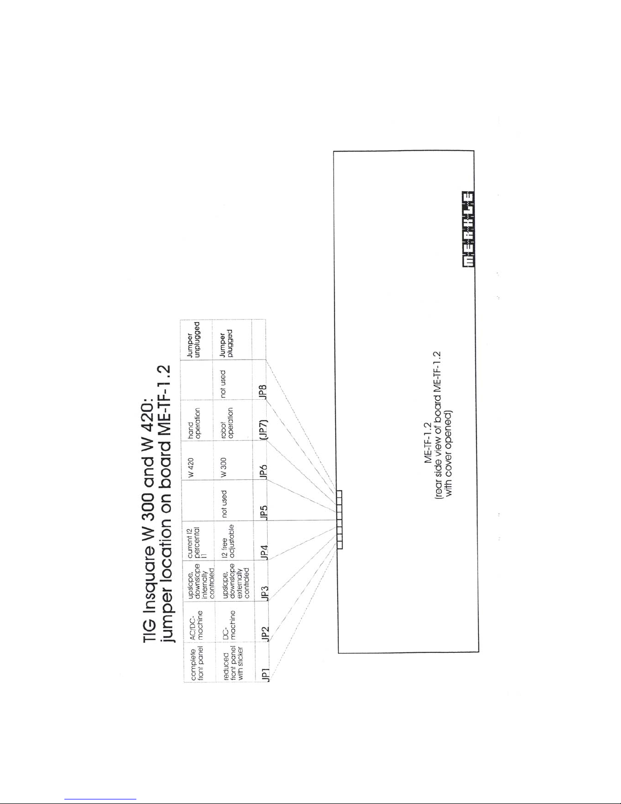
Jumper location on pcb ME-TF-1.2
Insquare W 300, W 420, W 600
16
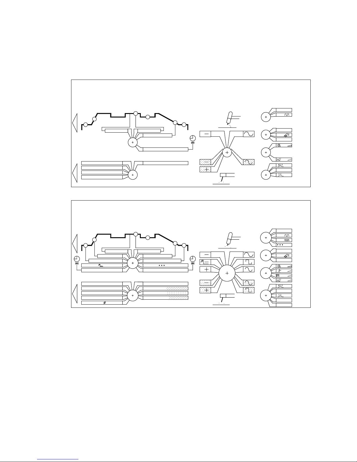
Reduced front panel
JP 1 on pcb ME-TF-1.2 plugged
timer spot welding
STROM I2 current I2
TIG-ELEKTRODE mm
igniton pulse
I1/t1
HF
I1
I1
I1
I1
ZÜNDIMPULS
HOTSTART - ZEIT timer
HOTSTART - STROM current
STROMNACHREGELUNG arc force
DISPLAY: SPANNUNG voltage
GAS
ZEIT t2 time t2
AC BALANCE + (%)
AC FREQUENZ frequency
PUNKTZEIT
GAS
0
PULS
PULS
0
LIFT-ARC
GASTEST
TEST,PROG
I2 (%)
STARTSTROM/initial curr.
ANSTIEG/upslope
ENDSTROM / final current
ABSENKUNG/downslope
STROM/current I1
ZEIT / time t1
DCDCDCDC
DCDCDCDC
DCDCDCDC
DCDCDCDC
ACACACAC
ACACACAC
ACACACAC
ACACACAC
I2/t2
0
STROM I2 current I2
LIFT-ARC
ZEIT t2 time t2
I1/t1
HF
I1
I1
ZEIT / time t1
DISPLAY: SPANNUNG voltage
AC BALANCE + (%)
AC FREQUENZ frequency
GAS
ACACACAC
AC
ACACAC
AC
ACACAC
ACACACAC
0
PULS
I2 (%)
ABSENKUNG/downslope
STROM/current I1
DCDCDCDC
DCDCDCDC
DCDCDCDC
DCDCDCDC ACACACAC
ACACACAC
ACACACAC
ACACACAC
I2/t2
Complete front panel
JP 1 on pcb ME-TF-1.2 unplugged
17
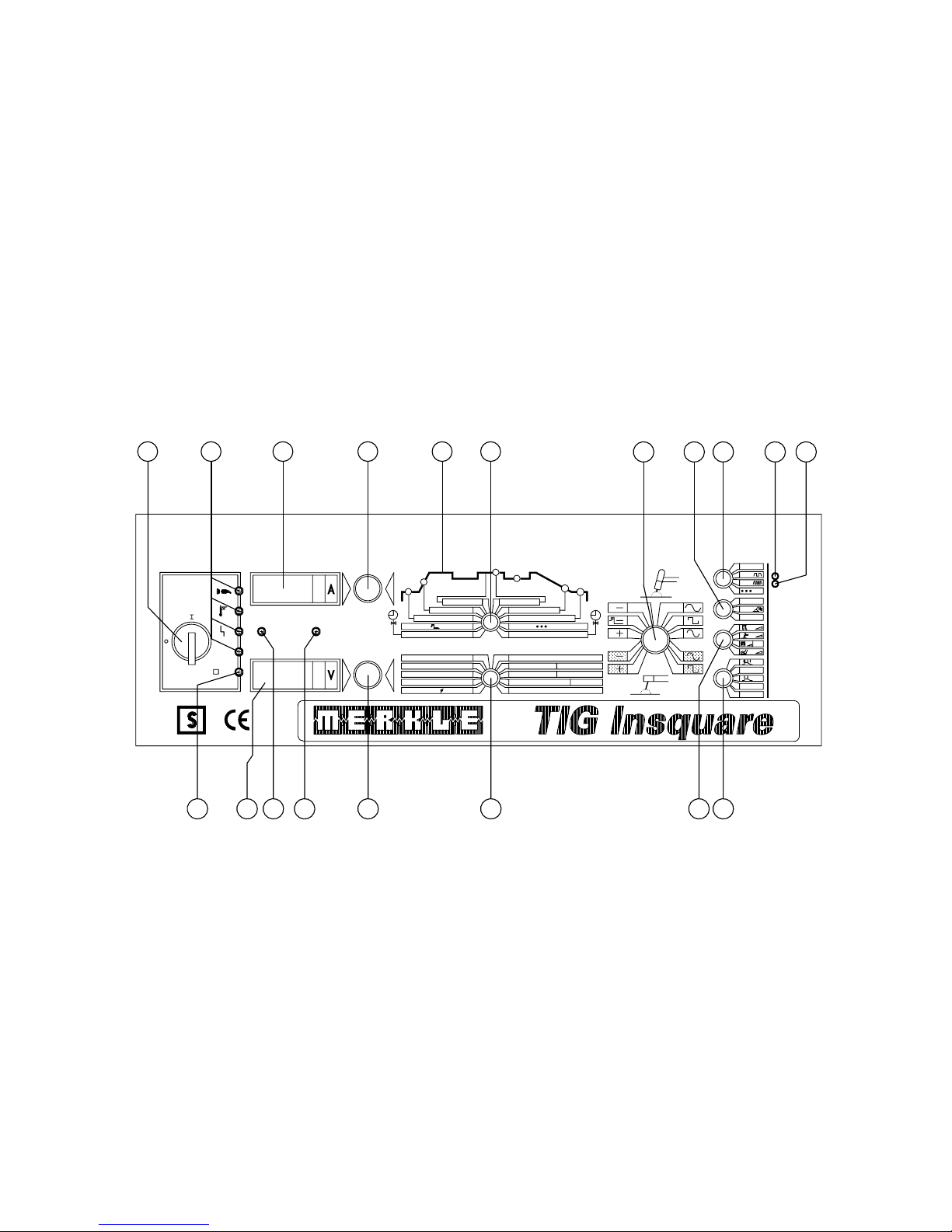
Front panel
E 2825-43
M
Q
C
Test
U
RMS
<48V
s
Hz
kHz
A
s
Hz
timer spot welding
STROM I2 current I2
TIG-ELEKTRODE mm
igniton pulse
ABSENKUNG-PILOTGAS
NACHSTRÖMUNG-PILOTGAS
PILOTGASMENGE
HOTSTART-ZEIT timer
HOTSTART-STROM current
STROMNACHREGELUNG arc force
DISPLAY: SPANNUNG voltage
KALTDRAHT
I1/t1
HF
I1
I1
I1
I1
s
HAUPTSCHALTER
MAIN SWITCH
PROGRAMM-NR.
ZÜNDIMPULS
HOLD
GAS
ZEIT t2 time t2
AC BALANCE + (%)
AC FREQUENZ frequency
PUNKTZEIT
GAS
PT11
0
PULS
PULS
0
LIFT-ARC
GASTEST
TEST,PROG
CAN
STATUS
I2 (%)
STARTSTROM/initial curr.
ANSTIEG/upslope
ENDSTROM / final current
ABSENKUNG/downslope
M
Q
C
STROM/current I1
ZEIT / time t1
M
Q
C
M
Q
C
DC
M
Q
C
DCDCDC
M
Q
C
M
Q
C
DCDCDCDC
DCDCDCDC
DCDCDCDC
M
Q
C
M
Q
C
ACACACAC
ACACACAC
ACACACAC
ACACACAC
I2/t2
12
7593 2
15 14
1
1713
8
10 11
64
16
18 19
18

8. Operation of the Unit
Control functions: INSQUARE W 300 / W 420 DC, INSQUARE W 300 / W420 AC/DC,
INSQUARE W600 AC/DC
1: Main switch
2: Selector switch "welding mode"
¾ Stick electrode-DC, plus-pole on electrode*
¾ Stick electrode-DC, minus-pole on electrode
¾ TIG-DC, plus-pole on torch electrode*
for extremly thin plates and metal foils, max.amps. 50A
¾ TIG-DC, minus-pole on torch electrode with positive
ignition pulse; improving ignition characteristics
welding highly oxidates sheets
¾ TIG-DC, minus-pole on torch electrode
standard position for TIG-DC-welding
¾ TIG-AC with positive ignition pulse, noice reduced
standard position for aluminium welding
¾ TIG-AC with positive ignition pulse, square wave
very stable arc even in pure aluminium
¾ Mixed-TIG-AC containing DC-parts
for welding without adding material and low loading of the torch electrode
¾ Stick electrode-AC, noice reduced
¾ Stick electrode-AC, square wave
3: Selector switch in connection with rotary switch 5 and LED-Display 7
¾ time gas preflow 0s…3s
¾ duration of the positive ignition pulse 2ms…100ms
¾ start current 5A…320A/420A
¾ time up slope 0s…2s
¾ welding current l (main curr) 5A…320A/420A
¾ time l (for curr l in pulse slow) 0,01s…2,5s in DC
0,05s..2,5s in AC
pulse frequency (in pulse fast) 51Hz…5kHz in DC
¾ time down slope 0s…20s
¾ final current 5A…320A/420A
¾ time spot w.( using spot welding) 0,1s…2,5s
¾ time gas postflow 0s…25s
4: Selector switch in connection with rotary switch 6 and LED-Display 8
¾ TIG-electrode diameter in mm 1,0/1,6/2,4/3,2/4,0/4,8
is limitating the max. amperage
in order to protect the TIG-electrode
¾ AC-frequency 50…200Hz*
a higher frequency gives a more
stable arc welding in lower amperages
¾ AC-balance (% plus pole at TIG-torch) 9%..91% 50Hz*
reduced in higher frequencies in order
to maintain the stability of the
welding arc: 36%..64% 200Hz*
19

¾ Time 2 (for current in pulse slow) 0,01s…2,5s in DC
0,05s…2,5s in AC*
¾ Welding current 2 10%…100% of curr l
¾ Voltage indication; hold-function after the weld
¾ Time hotstart 0s..l,5s
to assure ignition welding electrodes
¾ Current hotstart 10%..200% of curr l
¾ Arc Force 100%..250% of curr l
increases the welding current in order
to avoid adherence of the electrode. Using
cellulose electrodes, setting in pos max. is required.
The LED-display 7 resp. 8 indicates a non-valid parameter set by the selector switch and that is not
used for the welding process, for ex. AC-frequency when TIG-DC is selected.
* : Only mounted in the TIG-series Insquare W 300 AC/DC, W 420 AC/DC and W 600 AC/DC,
otherwise "no AC" is indicated on the LED-displays 7 and 8.
9: LED-indicator
Before the weld, the indicator is determined by the Position of the selector switch 3, during the
weld the indicator shows the Status quo of the welding process.
10: HOLD-indicator
When the hold-indicator is enlighted, the LED-display 7 shows the last value (amps) provided
that the selector switch 3 is set on pos curr 1. The LED-display 8 is indicating the welding voltage
(volts) provided that the selector 4 is set on pos voltage. After a few seconds, both LEDs switch
back to the preselected values.
11: Botton PROGRAM-NO.
Storage and activation of welding programs (adjustings of the parameters at the front panel)
12: LED-indications
Mains On
Over loading
Failure: Overloading or
mains overvoltage or
mains undervoltage or
waterpressure missing (beaking) or
activation of the protection device (Urms<48V) or
using a robot open emergency-OFF circuit of the welding unit.
Urms<48V: Indication of the protection device for no load
voltage without risk.
13: Botton-Test of the protection device (S-symbol)- only mounted in the AC-version
With this welding unit ace. norms EN 60974-1 and VDE 0544 welding jobs in confined areas can
be realised as a standard.
The correct function of the protection device can be checked as following:
- main switch ON
- the LED-indicator Urms<48V is enlighted
- do not use torch trigger. Do not touch torch electrode
or stick electrode clamped in the electrode holder
20

within 1 sec. the LED-indicator extinguishes U rms<48V
and the LED-indicator "failure" enlights.
By actuating the main switch pos switch OFF/ON, the generator is ready for work again.
14: Selector switch time functions
¾ Off
¾ Pulse slow (in DC and AC)
During time 1 flows curr 1 (selector switch 3), during
time 2 flows curr 2 (selector switch 4) ^
¾ Pulse fast (only in DC)
The fast pulse makes the DC-arc narrow.
The pulse frequency (selector switch 3) determines the
change from welding curr 1 to 2 with
a time share of 50% respectively.
¾ Spot welding
Spot welding time see selector switch 3;
internally times for the slopes are set to 0 sec. As soon as the welding current flows after
pushing the trigger, the spot welding time is counting. After this time has passed, the welding
process is automatically finished. A new start only is possible after releasing and pushing again
the trigger.
15: Selector switch ignition
¾ High frequency OFF
¾ HF ignition: The arc will be started by a high frequency ignition generator. The
tungsten electrode may not touch the work piece at the ignition process.
¾ Lift Arc ignition: Lift arc ignition is need, when TIG welding is performed close to
sensitive electronic devices. Touch down the tungsten electrode to the work piece, press
down the torch trigger and lift the electrode. While the tungsten electrode touches the
work piece a minimum current is activated in order to prevent the electrode from
sticking to the work piece.
16: Selector switch for welding current
¾ Adjusting on the front panel: current 1
(selector switch 3)
¾ Adjusting on the torch (option)
¾ Adjusting on the manual remote control. The value of curr 1 (selector switch 3) determines
the max. value of the variable resistor on the manual remote control turning it to the max. right.
¾ Adjusting on the foot pedal
The value of curr 1 (selector switch 3) determines the max. value of the foot pedal when it
is completely pushed down.
17: Selector switch operation mode
¾ 4-stroke-mode
1.stroke: push down the torch trigger :
ignition of the arc, the start current is flowing
2.stroke: release of the torch trigger:
the current slopes up to the selected value of current 1
in the period selected by the timer
21
 Loading...