

MERKLE HighPULSE 330 K, HighPULSE 280, HighPULSE 350 K, HighPULSE 350 RS, HighPULSE 350 Operation Manual
OPERATION MANUAL
Pulsed-Arc-Welding Units
HighPULSE 330 K

1
Content page
1 Security indications before introduction 3
2 Accident prevention regulations 3
2.1
Safety instructions
3
3 Duty cycle 5
4 Instructions to avoid interferences due to electromagnetic influences EMC 5
5 Technical Data 7
5.1
Synergic Pulse Welding Unit Model HighPULSE 330 K
7
6 Start Up 8
6.1
Installation of the Machine
8
6.2
Main Supply
8
6.3
Welding Torch
9
6.4
Gas Connection
9
6.5
Wire Installation
9
6.6
Earth Lead (Work Cable)
9
7 Operation of the Unit HighPULSE 330 K 10
7.1
Front Panel and Display Guide
10
7.2
Wire Feed Unit Display Guide
11
Standard functions 11
7.3
Switching the machine on
11
7.4
Choosing a Process
11
MIG/MAG- und Pulse-Arc Welding Programs 11
Interpulse Welding 11
MMA Welding 12
TIG Welding (Option) 12
7.5
Operation Modes
13
2-Stroke-Operation 13
4-Stroke-Operation 13
4-Stroke-Operation with selected program 13
The programming of Start Current, Down slope current/Time 13
7.6
Start Current (only programmable in special 4 stroke mode)
13
7.7
Down Slope Time (only programmable in 4 Stroke/4 Stroke Special Mode)
13
7.8
End Current (only programmable in 4 Stroke/4 Stroke Special Mode)
13
7.9
Safety Cut Off Switch
14
7.10 Digital Display Panel
14

2
7.11 Wire feed only Buttons
14
7.12 Gas Test
14
7.13 Selecting the Current control
14
Potentiometer 14
Wire Feed Unit Potentiometer 15
TEDAC 15
JOB-Functions 15
8 Maintenance and Accident Prevention 16
9 Cleaning 16
10 Aluminium Welding 17
11 MIG-Brazing 19
12 Trouble Shooting 20
12.1 Machine does not operate after switching on
20
12.2 Machine does not react on the torch switch
20
12.3 Machine has no or too low welding current
20
12.4 Welding Quality is not good
20
12.5 Problems with wire feeding and wire contacting
20
12.6 Burning of the wire core
20
Wire feeder system model DV-26 21
Wire feeder system model DV-26 21
12.7 Spare parts wire feeder model: DV-26
22
13 Torch - and Spare parts 23
13.1 MIG-MAG-welding torch model SB/SBT 350 G
23
13.2 Wiring diagram
26
13.3 Spare part list WK 230/300
32
13.4 Wiring diagram WK 230/300
32
14 Conformity Attestation HighPULSE 330 K 34
15 Conformity Attestation WK 230/300 35

3
1 Security indications before introduction
The unit device is built after the recognized standards. Safe works are nevertheless only possible
if you read the operating instructions and the safety regulations contained in it entirely and
obey strictly. Install yourselves by trained staff of our establishments or appointed dealers.
2 Accident prevention regulations
The following accident prevention regulation is applied for pulse arc welding unit, model
HighPULSE 330 K
BGV D1 (earlier VBG 15) * Welding, cutting and allied processes.
A copy of this regulation should be readily accessible in every welding shop. The stipulations of
this regulation are to be observed in the interests of safe and correct welding operation.
* Available from the trade association responsible or
Carl Heymanns-Verlag, Luxemburger Strasse 449, 50939 Cologne.
2.1 Safety instructions
This unit is manufactured according to the requirements and stipulations of EN 60974.1 / VDE
0544 part 1. BGV D1 (earlier VBG 15) of the trade association for precision engineering and
electrical engineering are as well valid.
1) In case of an accident, the cutting unit must be disconnected from the mains
immediately.
2) If electrical contact voltages arise, switch off the unit immediately, disconnect it from
the mains and proceed to inspection by a qualified electrician or by our Service
Department.
3) Before opening the unit, disconnect it from the mains supply.
4) Repair work may only be carried out by a skilled electrician or by our Service
Department.
5) Before the unit is put to operation, check it visually, as well as the torch and all cables
and connectors regarding possible external damages.
6) Personal protective equipment in accordance with DIN EN 175, DIN EN 379 and
DIN EN 169.
During the work, the welder’s body must be completely protected against radiation and
burns by means of protective clothing and face protection. Long gloves, aprons and
welding shields with welding filters conforming to DIN EN 470-1 and BGR 189
must be worn.
Synthetic clothing are excluded. Shoes must be closed, not opened (due to spatters). If
necessary, protective headwear must be worn (e.g. for overhead welding). If cover
glasses are used, these must be in accordance with the norms specified above.
As additional protection for the eyes against UV radiation, safety goggles with side
shields and corresponding face protection in accordance with BGR 192 and BGI 553
must be worn.
Accident prevention regulation BGV D1 § 27 stipulates that it is the responsibility of the
employer to provide suitable personal protective equipment, while § 28 stipulates that it
is the responsibility of the insured to wear suitable clothing.

4
7) Protection when welding under increased electrical risks
Welding rectifiers and welding power sources which can optionally be used for either
direct or alternating current must be marked "S" in accordance with EN 60974-1 and
BGI 534.
Use insulating materials to protect you against contact with electrically conductive parts
and damp floors. Wear dry, undamaged work clothing, long gloves and footwear with
rubber soles. Ventilate rooms, install extraction systems if required, and wear respiratory
protective equipment if necessary (see Procedural instructions BGV D1 § 27 and BGI 533,
Section 5).
8) In order to prevent stray currents and the effects thereof (e.g. destruction of electrical
protective ground conductors), the welding return cable (workpiece cable) must be
connected directly to the workpiece to be welded or to the table (e.g. welding table, gridtype welding table, workbench) supporting the workpiece (see BGV D1 § 20). When
installing the ground connection, assure that there is a good electrical contact (remove
rust, paint, etc.).
9) During welding pauses, the welding torch is to be laid down on an insulated surface or
hung up in such a way that it is not in contact with the workpiece and its support
connected to the welding power source (see § 20 BGV D1).
In the case of longer work pauses, the welding unit must be switched off and the gas
cylinder valve must be closed.
10) The shielding gas cylinder must always be protected against tumbling downing using a
safety chain.
11) Under no circumstances the unit may be put into operation while it is opened
(e.g. for repair work). Apart from the safety regulations, sufficient cooling of the
electrical components provided by the fan cannot be guaranteed.
12) In accordance with BGV D1 § 5, people in the vicinity of the arc must also be informed
of the hazards and protected against them. Safety partitions (“welding safety curtains”)
must be erected in accordance with DIN EN 1598.
14) No welding work may be carried out on containers in which gases, fuels, mineral oils or
similar substances have been stored Öeven if they have been empty for a long timeÕ
(risk of explosion). See § 31 of accident prevention regulation BGV D1.
15) Welds which will be subjected to high loads and which need to meet specific safety
requirements may only be carried out by specially trained and qualified welders.
15) Never bring the torch close to your face.
16) In areas at particularly high risk of fire, the welder must obtain a welding permit and
have this on his person throughout the duration of the welding work. On completion of
welding, a fire-guard must be delegated to ensure fire protection.
17) Ventilation measures must be applied in accordance with BGI 553, Section 9.
18) The hazard to eyesight must be indicated by means of a sign at the work site "CAUTION!
Do not look into the arc!".

5
3 Duty cycle
The duty cylce measurings have been carried out in accordance with
EN 60974-1 / VDE 0544 part 1 (10 min working period).
60% duty cycle means:
After a 6 min. welding period a 4 min welding pause must be respected. The electrical
components are thermally protected against overheating.
4 Instructions to avoid interferences due to electromagnetic influences EMC
The welding unit has been manufactured in accordance with the requirements of guideline
EN 60974-10 / VDE 0544-part 10 regarding electromagnetic compatibility. It is nonetheless the
responsibility of the user to ensure that the welding equipment is installed and operated in
accordance with the manufacturer’s instructions. If electromagnetic interference is detected, it
is the responsibility of the user of the welding equipment to find a solution with the technical
assistance of the manufacturer. In some cases, it may be sufficient simply to ground the welding
current circuit. In other cases, it may be necessary to build a complete shield for the welding
power source and workpiece using the input filters. In all cases, electromagnetic interference
must be reduced to avoid any possible malfunctions.
Note: For safety reasons, the welding current circuit may or may not be grounded. No
modifications may be made to the grounding without the approval of an expert who is able to
determine whether the changes might increase the risk of accidents, e.g. by allowing parallel
welding current return paths which could destroy the ground conductors of other equipment.
Further instructions are contained in TEC 974-XX "Arc welding equipment – installation and
use".
a) Evaluation of the installation site
Before installing the welding equipment, the user must evaluate potential
electromagnetic problems in the vicinity. The following must be taken into
consideration:
a. Other power cables, control cables, signal and telecommunication cables above, below
and next to the welding equipment
¾ Radio and television transmitters and receivers
¾ Computers and other control devices
¾ The health of people in the vicinity, e.g. use of heart pacemaker and hearing aids
¾ Calibration and measuring equipment
¾ Interference immunity of other devices in the vicinity. The user must ensure the
electromagnetic compatibility of other devices used in the vicinity. This may require
additional safety measures.
b) Procedures to reduce emitted interference
1) Mains supply
Welding equipment is to be connected to the mains in compliance with the
recommendations of the manufacturer. If interference occurs, it may be necessary to
take additional precautions, e.g. filters for the mains connection. Make sure that the
power cable of welding equipment is installed in a fixed position shielded by means of a
metal conduit or similar. The entire length of the shield must be electrically connected.
The shield must be connected to the welding power source in the way to obtain a good
electrical contact between the metal conduit and the housing of the welding unit.

6
2) Maintenance of the welding equipment
Welding equipment must be maintained regularly in accordance with the
recommendations of the manufacturer. All access and service doors and covers must be
closed and fastened securely when the welding equipment is in operation. No
modifications whatsoever may be made to welding equipment with the exception of
modifications and adjustments specified in the manufacturer’s operating instructions.
3) Welding cables
Welding cables should be kept as short as possible and routed close together on or near
the floor.
4) Equipotential bonding
It is advisable to interconnect all metallic parts in and next to the welding equipment.
Metallic parts connected to the workpiece can, however, increase the risk of the welder
receiving an electric shock by touching these metallic parts and the electrode
simultaneously. The welder must be electrically insulated against all these connected
metallic parts.
5) Grounding the workpiece
If the workpiece is not connected to the ground for electrical safety reasons, or due to
the size and position of the workpiece, e.g. steel structure or outer wall of a ship,
grounding the workpiece may in some cases, but not all, reduce emitted interference. It
must be ensured that grounding the workpiece will not increase the risk of accidents for
the user and cannot cause the destruction of other electrical equipment. If necessary,
the grounding of the workpiece must be carried out by means of a direct connection to
the workpiece. In countries where a direct connection is prohibited, the connection must
be made by means of suitable reactors, selected in accordance with national regulations.
6) Shielding
Selective shielding of other cables and devices in the vicinity can reduce interference
problems. For special applications, it may be worth considering shielding the entire
welding system.

7
5 Technical Data
5.1 Synergic Pulse Welding Unit Model HighPULSE 330 K
Primary:
Power supply: 3 x 400 V (3 x 440 V / 3 x 220 V)
Frequency: 50/60 Hz
cos phi: 0.99
Synergic pulse / MIG operation:
Open circuit voltage: 57 V
Welding voltage: 15-30.5 V
Welding current: 25-330 A
Duty cycle 35 %: (10 min.) 330 A (40°C)
Duty cycle 60 %: (10 min.) 280 A (40°C) 330 A (20°C)
Duty cycle 100 %: 250 A (40°C) 280 A (20°C)
Prim. contin. power: 12.5 kVA
Prim. contin. Current: 18 A
Prim. max. current: 23 A
TIG operation:
Open circuit voltage: 57 V
Welding voltage: 10-23.2 V
Welding current: 10-330 A
Duty cycle 35 %: (10 min.) 330 A (40°C)
Duty cycle 60 %: (10 min.) 280 A (40°C)
Duty cycle 100 %: 250 A (40°C)
Prim. contin. power: 11.5 kVA
Prim. contin. Current: 16 A
Prim. max. current: 21 A
MMA/stick electrode operation:
Open circuit voltage: 57 V
Welding voltage: 20-33.2 V
Welding current: 20-330 A
Duty cycle 35 %: (10 min.) 330 A (40°C)
Duty cycle 100 %: 250 A (40°C)
Prim. contin. power: 13.1 kVA
Prim. contin. Current: 19 A
Prim. max. current: 25 A
Protection class: IP 23
Insulation class: H
Cooling: AF
Arc length: automatic energy control
Program capacity: 256 programs
Programs: MIG/MAG, MIG Pulse, Interpuls,
MMA/stick electrode, DeepArc,
TIG DC (option), MIG brazing
Program selection: material, wire diameter and gas
at the display
Operation modes: 2-stroke, 4-stroke, 4-stroke with
start current, interval, stitch
Gas check: button with hold function
and automatic switch off

8
Digital display: current, voltage, wire feed speed
and material thickess with
pre-display and hold function
Energy adjustment: at the machine,
at the TEDAC torch,
job mode
LEDs: Mains, failure, temp. protection,
hold function
Adjustable parameters: choke inductance, pulse shape
Automated functions: wire burn back
soft start (programmable)
Job mode: 512 jobs programmable
Power source: inverter
Sockets 50 mm²: earth lead and electrodecable
Torch cooling: gas (option: water)
Mains supply cable: 4 x 2.5 mm², 5 m long with
Plug 3 x 400 V / 32 A
Gas hose: 2 m
Handle: on top of the machine
Norm: EN 60974-1 "S" / CE
Weight: 36.5 kg
Dimensions: 600 x 300 x 565 mm
Wire feeder: compact mounted, Model DV-26
Supply: 26 V-DC
Wire feed motor: DC motor with worm gear dirve
0.5 - 25 m/min.
Wire feed system: 4-roller-drive DV-26
Reel hub assembly: D 300/15 DIN 8559
Torch connection: EURO connector
Standard wire equipment: mild steel 1.2 mm
6 Start Up
6.1 Installation of the Machine
If the unit is brought from cold ambient temperatures into a tempered room, for example due to
transportation or from unheated storage depots, it must be adapted before being put to
operation a certain time according to the temperature difference onto the ambient temperature.
Place the machine at least 0.80 m from a wall etc. to guarantee the cooling air can go
through the unit. The room temperature should not exceed 40°C.
The room were the unit is placed should have a low degree of humidity
(max. 50 % at 40°C, max. 90 % at 20° C).
The unit has passed the quality control in accordance with IP 23.
The air in the surroundings must be free from extreme quantities of dust, free from acides and
corrosive gases etc. Otherwise use air filters.
6.2 Main Supply
The main supply must be connected by a trained person. The main supply voltage is displayed on
the front or rear panel of the machine. A connection to ground (GND) must be done.

9
6.3 Welding Torch
Connect the torch to the Euro-connector.
6.4 Gas Connection
Place the gas bottle on the gas bottle holder and secure it with the safty chain. Remove
the cap and open the bottle momentarily to purge the valve. Install the regulator on the
bottle valve. Connect the gas hose from the machine to the pressure reducer. Slowly open
gas valve and set the gas flow.
6.5
Wire Installation
Place the wire spool over the wire drive. Loosen the end and cut off the bent end section.
Hold the wire to prevent unwinding of the spool. Open the lightning lever and lift the
pressure finger. Feed the wire into the wire feed guide. Push the wire forward onto the
wire drive roller grooves. Close the lightning lever and switch on the machine.
Check the wire feeding: Place your hand 10 cm in front of the contact tip. Let the wire run
into your hand. If the wire is running, the pressure of the drive rollers is o.k.
6.6 Earth Lead (Work Cable)
The earth lead must have an excellent ground. The clamp should be attached to a clean, paint
and rust free area on the work piece or on the welding table.
10
7 Operation of the Unit HighPULSE 330 K
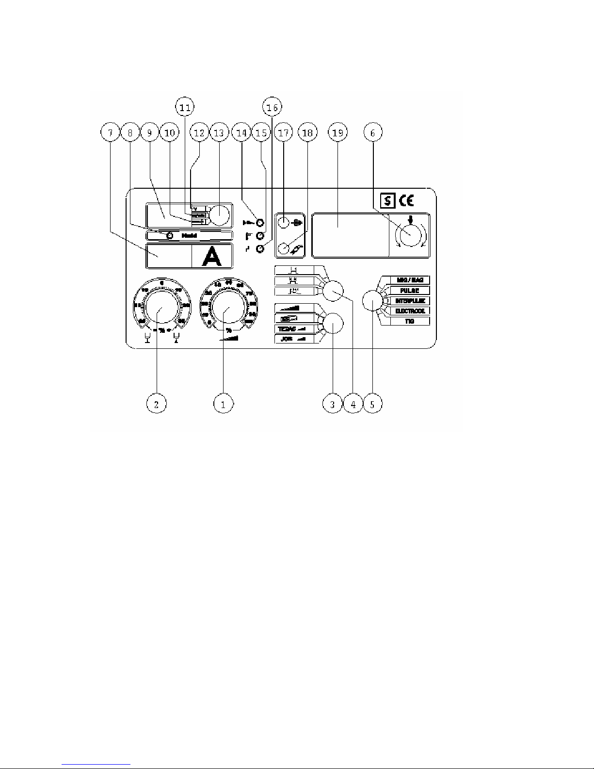
7.1 Front Panel and Display Guide
(see diagram)
0: mains power switch
1: current potentiometer dial (also on wire feed unit)
2: arc length correction dial (also on wire feed unit)
3: welding process control method switch
4: torch trigger mode switch
5: welding process selector switch
6: rotary program and confirmation (press) selector switch
7: digital current indicator panel
8: LED hold switch
9: digital indicator panel (shared)
10: material thickness (mm)
11: wire feed speed (m/min.)
12: voltage (V)
13: selector switch for upper display
14: LED mains connection
15: LED overheat
16: LED fault indicator
17: wire feed test switch (also on feed unit)
18: gas flow test switch
19: MultiFunktionalDisplay (MFD)

11
7.2 Wire Feed Unit Display Guide
25: current potentiometer
26: arc length correction potentiometer
27: wire feed test switch
28: current remote switch (Option)
29: remote arc length correction switch (Option)
30: remote connection socket (Option)
Standard functions
7.3 Switching the machine on
To switch on the machine turn the mains power switch to position 1. the water pump will then activate
and the machine is ready to use. Should LED 16 light up the first check if enough coolant is in the tank,
or if the water pump has activated.
7.4 Choosing a Process
Using rotary switch 5 the user can select between the MIG/MAG, Pulse Arc, Interpuls, MMA or TIG
welding processes.
MIG/MAG- und Pulse-Arc Welding Programs
Rotary switch 5 must be switched to either the MIG/MAG or Pulse position. The desired welding
program may now be selected in conjunction with Rotary switch 6 and the use of the Multi Function
Display (MFD 19). Turning Rotary switch 6 through a clockwise direction will enable the following Main
Menus:
Material
New Job
Throat thickness
Impedance (MIG/MAG) or Pulse form (Pulse)
In the Main Menu select Material, by pressing the Rotary switch (6) once a secondary menu listing all
materials will appear, by turning switch 6 and pressing on the desired material that material is selected
and the next Menu field is activated. The next Menu field is titled Filler wire size, by turning and
pressing Rotary switch 6 the desired filler wire size can be selected. The final sub menu to appear is
titled Gas, again through turning and pressing Rotary switch 6 the desired gas can be selected from the
list. By pressing switch 6 one last time the menu table is exited and the chosen program is activated and
ready for use.
Using Dial (1) the desired welding current may be selected, with Dial (2) the Arc-Length (Arc Trim) can be
individually adjusted for each job. If the user wishes to use the wire feed unit to select the desired
current and arc length (switches 25, 26), then the symbol for the Wire feed unit must be selected using
switch 3.
Using switches 28, 29 (Option) the control of Current and Arc length setting is transferred to a remote
regulator, i.e. push me pull you torch.
Interpulse Welding
Rotary switch (5) must be rotated into the inter-pulse position. Using the MFD (19) and rotary switch (6)
the following 5 Main Menu’s be activated;
Material

12
New job
Throat thickness
Interpulse
Pulse form
Using rotary switch (6), select from the main menu ‘Interpulse’, by now pressing the switch (6) the cursor
will return to the program last used in this mode. The programmable inter-pulse range runs from 0 –
100. The smaller the number the quicker the Pulsing, this gives the weld bead a very fine Scaling
appearance. A larger number would indicate an overall slow Pulse and consequently a larger scaling
appearance in the weld bead. To save the selected inter-pulse setting simply press switch (6) once.
MMA Welding
Rotary switch (6) must be rotated into the ‘Electrode’ position. Important, no load voltage is
immediately present at the cable connection plugs. Using the MDF (19) and the Rotary switch (6) the
following 4 sub-menu’s can be accessed;
Hotstart t (time)
Hotstart I (current)
Arc force (current trim)
New Job
The relevant settings can be selected through these sub-menus and altered to suite. The required
settings can also be programmed under a job number.
Hotstart
Hotstart is a process whereby the current to the electrode is increased for a programmed time during the
start phase of the MMA process.
Available settings: Hotstart time 0 – 2s
Hotstart current 20 – 450/550 A
Arcforce (current trim)
• A current increase is delivered through the electrode as a result of the electrode coming into
contact with the weld pool.
• The increase in current ensures that the electrode does not stick to the work piece, however
should this phenomenon occur the current is automatically reduced in order to avoid the
overheating of the electrode.
TIG Welding (Option)

13
7.5 Operation Modes
2-Stroke-Operation
Operation Switch (4) into the „2-Stroke“ position.
Press trigger and hold, welding starts, release trigger, welding program ends.
4-Stroke-Operation
Operation Switch (4) into the „4-Stroke“ position.
1) Press trigger and hold – welding pre-program initiates up to start current
2) Release trigger – main welding current is initiated
3) Press trigger and hold – current will reduce as programmed, up to end current setting
4) Release trigger – the welding program will end
4-Stroke-Operation with selected program
Operation switch (4) into the spezial 4 stroke position.
1) Press trigger and hold – programmed pre-program initiates up to selected start current
2) Release trigger – programmed welding current is initiated
3) Press trigger and hold – programmed down slope and end current is initiated
4) Release trigger – programmed end gas time initiated, when complete the program is ended
The programming of Start Current, Down slope current/Time
7.6 Start Current (only programmable in special 4 stroke mode)
Program selector switch (5) must be r position ‘MIG/MAG’, ‘Pulse’ or ‘Interpulse’. Using Rotary Switch (6)
in conjunction with the MFD (19) select the Parameter Start Current then press Rotary switch (6) once,
the display will switch to the last programmed setting. Using Rotary switch (6) turn until the desired
current is displayed.
• Programmable settings: 0 to a maximum value corresponding to the chosen
materials programmed parameters.
In order to leave the program with the saved setting, simply press switch (6) once, the cursor will the
return to the initial menu ‘Start Current’.
7.7 Down Slope Time (only programmable in 4 Stroke/4 Stroke Special Mode)
Selection and programming of the Down slope time is carried out by turning Rotary switch (6) until the
menu heading ‘Down Slope’ shows in the MFD and then press Switch (6) once to select. By turning
switch (6) select the value, in seconds, required.
• Programmable settings: 0 – 10 seconds
To confirm and save the settings simply press Switch (6) once. The cursor will return to the Down Slope
time initial menu.
7.8 End Current (only programmable in 4 Stroke/4 Stroke Special Mode)
Selection and programming of the End Currant is carried out by turning Rotary switch (6) until End
Current shows in the MFD (19), press switch (6) once to enter the menu side. The current level is then
selected by turning Rotary switch (6) until the desired current is shown.
• Programmable Settings: 0 to a maximum value corresponding to the chosen materials
programmed parameters.
To confirm and save the settings simply press Switch (6) once. The cursor will return to the End Current
time initial menu.

14
7.9 Safety Cut Off Switch
As an additional safety feature, if after 2 minutes no arc is initiated then the welding program will be
ended automatically.
7.10 Digital Display Panel
The welding machine is equipped with two 3-figure digital displays (7 & 9). These control the indicated
setting possibilities and the ‘Hold’ function; to this end before you begin welding or after you have made
a current (7), voltage (12), wire feed speed (11) or material thickness input change, these digital displays
will indicate the relevant condition that will be delivered.
After welding is complete the machine will retain the last used complete welding conditions until such
time as a change is made manually to the conditions. This is shown through LED (8) lighting up,
indicating that the program has been held.
Upper Display (9)
Using rotary switch (13) select between:
Welding Voltage (12)
Wire feed speed in m/min (11)
Material thickness in mm (10)
In MMA mode the No Load Voltage would be indicated, during welding the actual Welding Current
would be indicated.
Lower Display (7)
This display will always show the Welding Current in Ampere.
7.11 Wire feed only Buttons
Using button (17) on the Main Machine or button (27) on the Wire Feed Unit, the welding wire can be
fed through to the torch current free.
7.12 Gas Test
Using button (18) the gas flow can be tested as follows:
Press button (18): the gas valve will be activated
Release button (18): the gas valve remains active
Press button (18): the gas valve will be de-activated.
As an added safety measure the gas valve will automatically close after 10 seconds should the button
not be manually operated during testing.
7.13 Selecting the Current control
Rotary switch (3) is used to select between which method of welding current control is preferred.
Potentiometer
With rotary switch (3) in the upper position the welding current and the arc length correction can be
controlled using potentiometers (1 & 2) on the main welding machines control panel. Using switch (28)
the control is transferred to which ever form of remote control is connected at that time.

15
Wire Feed Unit Potentiometer
With rotary switch (3) in the second position, control of the welding current and arc length correction is
controlled using potentiometers (25 & 26) on the front face of the wire feed unit.
TEDAC
With rotary switch (3) in the TEDAC position the control of the welding current and arc length correction
is controlled through the thumb switch mounted in the back of the welding torch itself. Warning: the
maximum current available is determined through the position of welding current potentiometer (25) on
the front face of the wire feed unit.
JOB-Functions
New JOBs
Rotary switch (3) must be set to control the current setting through the main control panel (1); the wire
feed unit (25), or the TEDAC torch system. Using the multi function display (MFD19) and rotary switch
(6) select the desired welding program, then with the help of the welding current potentiometer and the
arc length correction potentiometer set the desired welding conditions.
With rotary switches (5, 6) select the desired operational mode and welding process. The saving of the
new welding conditions is achieved using rotary switch (6). The switch (6) must be turned until the main
menu heading ‘New Job’ appears, the number of the next free program slot will then appear in the multi
functional display (MFD19) window, by pressing switch (6) once the program will be saved to the
machines memory and the number of that particular program will appear the MFD (19).
The possibility of saving the desired welding conditions to a job number other than the next available
free job is also possible; this is achieved through rotary switch (6). As above the rotary switch (6) must
be used to select the main menu ‘New Job’, when the next available free job appears in the multi
functional display rotary switch (6) can then be used to select the desired program number, by then
pressing rotary switch (6) twice the welding conditions will loaded into the chosen slot. The MFD (19)
will then return to the main menu heading ‘New Job’ to indicate that the transaction was successful.
Important: When a job is saved to a specific job number the complete job including all the fine tuning
elements of the program is saved (e.g. Inductance, pulse form, start current, down slope time, 2-stroke,
4-stroke, MIG/MAG, pulse-arc etc, etc).
Load saved JOB
If there are a number of jobs saved in the machines memory banks, then these programs can be
reselected and loaded back into the machine using rotary switch (3). The menu heading ‘job’ in the MFD
(19) is selected, the cursor will then show ‘Load Job’, again in the middle of the MFD (19) the job shown
in the display is now active and can be used. Notice: Job that appears in the MFD (19) will always be the
last saved program.
Should another previously saved program be required this can be loaded back into the welding machine
by pressing rotary switch (6) once, the cursor will jump across to the smaller job number field in the
bottom right of the MFD (19), by turning rotary switch (6) the desired program can be selected and is
now active. Only saved job programs can be reactivated.
If a TEDAC torch system is being used, then using the thumb control button mounted on the torch a
maximum of 10 programs can be selected and activated through this system. The programs should be
selected in ascending order through the MFD (19) i.e. the lowest number should be the first job.

16
Change JOB
The parameters in each saved job can be adjusted at any time. To achieve this rotary switch (3) must be
in the “JOB” positions, then using rotary switch (9) select the “Change” sub heading, now each individual
parameter is accessible and can be changed through the turning and pressing of rotary switch (9).
8 Maintenance and Accident Prevention
The maintenance of the welding machine consists of a regular cleaning and inspection. It
depends on the environment of the working area and the working hours.
The machine should be cleaned in regular intervals to guarantee a proper operation. The length
of the cleaning interval depends on the operation time, surrounding atmosphere etc.
ATTENTION: Before opening the welding machine, make sure
that it is disconnected from the mains supply. Wait for
components to be sufficiently cooled down !
Wait until the capacitors are discharged (appr. 3 min.)!
9 Cleaning
IMPORTANT:
!!! Before opening the machine, disconnect it from mains !!!
Wait until the capacitors are discharged (appr. 3 min.)!
Welding unit: Open the side covers. Remove dust from all parts of the machine.
Blow away the dust at the pcbs of the inverter withcompressed air,
reduced pressure (appr. 0,5 – 1 bar). We recommend to clean the unit
in regular periods.
Welding torch: Control the welding torch after welding of 50 kg wire. Remove, clean
and replace the wire core. Clean with a cleaning solvent. Blow dry with
reduced compressed air. When replacing the wire core, insure that there are
no kinks. The gas nozzle must be sprayed with a silicon-free spray to
prevent the weld spatters from sticking to the nozzle. The contact tip is
a consumable item and must be replaced as required.
Attention: ⇒ Do not oil the wire core or the drive roller on the wire feed unit.

17
10 Aluminium Welding
1. Aluminium welding wire:
- Wire diameter 0.8 mm only with push pull torch
- Wire Al-Mg 3/5/4.5 Mn (1.0 mm), Al-Si, Al 99.5 (1.0 and 1.2 mm) torch lead max. 3 m
- For welding wire 1.6 mm we recommend a torch with a long torch head
- Do not store alu wire without the plastic protection cover. Do not use alu wires with oxid.
2. Teflon liner:
- For wire 0.8 - 1.2 mm we recomend the teflon liner (red, 2.0 x 4.0) mm (part-no.
022.1.0586)
- For (1.2) and 1.6 mm teflon liner (black, 2.7 x 4.7) (part-no. 022.1.0588)
- The carbon teflon liner must be installed without any break from the contact tip to the
drive roller
- Fix the clamping nut at the Euro connector only by hand
4. Wire feeding rollers:
- Exchage the two lower roller to aluminium rollers (U-groove), the rollers at the to may
remain pressure rollers without a groove
5. Pressure of the rollers:
- Reduce the pressure to a minimum.
- When the alu wire is stoped at the contact tip the rollers must turn without transporting
the wire.
6. Insertion of the wire:
- Insert the wire without a contact tip at the torch.
- Hold the torch cable straight, outherwise the wire could go through the line and the torch
lead.
7. Welding torch:
- We do not recommend the torch SB/SBT 307 G or SB/SBT 350 G for aluminium welding.
Use a ceramics gas distributor (not fibre glas). Due to the high temperatures the fibre glass
may emit a gas which influences the welding process.
- The torches SB/SBT 502 W and SB/SBT 600 W have an open cooling system. Assures that
the componets are tightly fitted. Only minimum parts of water will make the aluminium
welding impossible.
8. Protective gas:
- We recommend argon 4.6, mixtures argon-helium can be used for thick aluminium plates
to avoid or reduce a pre-heating.

18
- Gas flow for a gas nozzle 17 mm:
wire 1.0 mm: aprox.12-14 l/min.
wire 1.2 mm: aprox. 14-16 l/min.
wire 1.6 mm: aprox. 18-22 l/min.
Avoid smaller gas nozzles.
If the gas hose between gas valve and cylinder is long, an impulse of too much gas is ejected
during the ignition process which could cause porosity. Our wire feeder boxes have a special
reduction device installed.
- For gas hoses longer than 10 m we recommend the installation of a pressure regulator
inside the welding unit.
- We recommend a regulator with an integrated ball-flowmeter.
9. Position and distance of the torch:
- Aluminium is welded in forward position, the torch is tilt aprox. 10 - 20°.
- Distance torch to work piece aprox. 10-15 mm. If the distance is too large, the protective
gas shield is not assured.
- Avoid draught (air movement in the room).
10. Cleanliness:
- Aluminium work pieces must be without any dirtying. Clean with alcohol or special
aluminium cleaner
- Avoid the storage under high humidity.
- Remove oxid when aluminium pieces have been stroed a lon time.
11. Additional wire equipment:
- In our general catalogues in section 10 we offer complete packages for wire equipments.
12. Special 4-stroke:
- We recommend to operate in the special 4-stroke mode with a higher start current. The
start current, the down slop and the final current can be adjusted at the digital control
unit.

19
11 MIG-Brazing
Increasing demands to reduce damages due to corrosion are the reasons for working more and
more with surface treated steel plates. Zinc is actually the best choice due to an ecomomic
solution.
Large quantities of galvanized steel plates are found in car production, building constructions,
ventilation and climate technique and in the domestic sector.
Zinc begins to melt at approximately 420° Celsius and vaporization starts at approximately at
906° Celsius. These caracteristics do not lead to good results during the welding process
because the temperature of the welding arc using steel wire rises up to appr. 1450-1520° C,
melting temp. at 2700° C. This high temperature would instantly start the vaporization process
of the zinc. Furthermore, vaporization and oxides can provoque porosity, failures or fissures in
the weld and instability of the arc. Therefor, galvanized steel plates require less heat input.
The notion „ MIG-Brazing“ stands for a hard-solder process carried out by MIG/MAG- or PulseArc welding units. Different wires are used :
CuSi 3 wire for joining galvanized steel plates. Other wire compositions ( f. ex. CuAl 8 or AlBz 8)
if aluminized steel plates or stainless steel are used.
The advantages of using these wires are:
¾ no corrosion at the welding joint
¾ minimized spatters
¾ maintaining of the zinc surface
¾ low heat input
¾ easy finishing works of the welding joint
¾ cathodic protection of the material in the close surroundings of the welding joint
As shield gas pure argon or mixtures with argon (Ar 97,5 % - CO2 2,5 %) are used. As a result an
almost blank welding joint surface is achieved. When thicker zinc surfaces are used (more than
15 micro-m) the arc gets instable due to the higher output of zinc vapours.
In this case a short or a spray arc with low arc voltages can be an advantage.
We recommend to mount a steel liner to the torch lead.
The PULSE ARC welding unit model HighPULSE 330 K is a multiprocess welding unit equipped
with welding programs as a standard including welding programs for joining galvanized and
aluminized steel plates. The setting of the energy is realized or by means of one botton (synergic
operation mode) at the machine or by the remote control system TEDAC mounted at the torch.
The steel plates can be brazed together or in the pulse mode or in the MIG/MAG mode. The low
weight offers an easy handling of the unit to different working places.

20
12 Trouble Shooting
12.1 Machine does not operate after switching on
a) Check main supply
b) Check main fuses
12.2 Machine does not react on the torch switch
a) Problem at the torch switch
b) Check internal fuses
12.3 Machine has no or too low welding current
a) Main relais is not working
b) Bad or no contact at the earth lead
c) Torch hose completely or partially broken
d) Problem with rectifier or Fet- switches in the machine
e) Only 2 main phases are connected, check main fuses
12.4 Welding Quality is not good
a) No or too low gas flow
b) Air is mixed into the protective gas. Open gas valve and close it again.
Gas pressure must remain in the gas hose. Check at the regulator.
c) Gas nozzle or tip holder are covered with spatters. Gas flow is not o.k.
d) Tip holder is not fixed properly. Air is mixed into the protective gas via the wire
e) Extremly oxidated workpiece.
f) Air is comming to the welding area because of wind.
12.5 Problems with wire feeding and wire contacting
a) Hole in the contact tip has wrong diameter or contact tip must be changed.
b) Wire core is extremly dirty.
c) Kinks in the wire core.
d) Wrong diameter of the wire core.
e) Pressure at drive rollers is to low.
f) Wrong or used drive rollers.
g) Welding wire is not running in the axis of the drive rollers.
h) Mechanical resistance of the welding wire is too high.
12.6 Burning of the wire core
a) Electrical connection between wire feed gear and welding current. Check wire
feeder for pieces of welding wire in the gear.
b) Check power cable or flange nut in the Euro-connector for a good connection.

21
Wire feeder system model DV-26

22
12.7 Spare parts wire feeder model: DV-26
Pos. Bezeichnung Artikel-Nr.
1 Getriebewinkel DV-26 / Gear angle DV-26 113.584
2 MIG/MAG Zentralanschluss komplett / MIG/MAG Euro connector cmpl. 114.606
3 Isolierflansch DV-21 - 26 – 31 / isolation flange DV-26 113.572
4 Isolierbuchse DV-26,31,30/4 lang / isolation socket DV-26,31,30/4 long 111.052
5 Scheibe 5,3 Form B / plate 3,5 form B 090.0.1204
6 Linsenflachkopfschraube M 5x16 / allen key head screw M 5x16 090.1.0825
7 Gasnippel DV-26,31 / gas nipple DV-26,31 110.576
9 Linsenflachkopfschraube M 5x16 / allen key head screw M 5x16 090.1.0825
10 Isolierbuchse / isolation socket DV-26 113.568
11 Kappe rot für Drehknopf klein / Cap for knop 15 mm 003.0.1522
13 Rändelschraube GN 591 / Roller ring 110.568
14 Auslaufdüse / Outgoing nozzle DV-26 110.554
15 Isolierung / isolation DV-26 113.570
16 Wippe links / rocker left DV-26 110.538
17 Wippe rechts / rocker right DV-26 110.540
18 Bolzen SW 10 / bolt SW 10 for DV-26 113.576
19 Spring-Stop-Mutter M6x1x3,2 / spring washer M6x1x3,2 113.578
20 Gewindestange / threaded rod 110.546
21 Druckstück am Spannbügel / pressure piece on pressure lever 110.548
22 Druckfeder am Spannbügel / pressure spring on pressure lever 110.578
23 Druckschraube am Spannbügel / pressure screw on pressure lever 110.550
24 Linsenflanschkopfschraube M 5x16 / allen key head screw M5x16 090.0.0825
25 Zylinderstift 6 m6x32 / cylindrical dowel 6 M6x32 090.0.8460
26 Ritzel DV 26 / gear cog 113.580
27 Senkschraube M 4x12 mit Schlitz / counter sink screw M4x12 with slot 090.0.5815
28 Rosettenscheibe / rosett washer 090.0.1221
29 Motor DV-Getriebe / DC wire feed motor 002.0.2630
30 Linsenflanschkopfschraube M 6x12 / allen key head screw M5x16 090.0.0899
31 Bolzen DV 26 für Schutzabdeckung / bolt DV-26 for protective cover 113.582
32 Führungsstück / Guidance tube 113.566
33 Zyl-Schraube M 5x 12 verz. mit Innen-Skt 8.8 / cylinder screw M5x12 090.0.2565
34 Einlaufseele 0,14 m / Insertion sleeve, DV-26 012.0.0377
35 Antriebsring 1,0 + 1,2 Stahl / Drive ring steel 1.0 + 1.2 012.0.0272
36 Druckrolle / Pressure roller 113.742
37 Rollenbolzen / roller bolt 110.544
42 Rändelmutter / Guidance tube pvc 110.558
44 Zahnrad Z=19 m=2 / toothed wheel z=19 m=2 012.0.0263
45 Passstück 4x4x10 DV-30 für Zahnrad / adapter 4x4x10 for toothed
wheel
090.0.8810
46 Linsenflanschkopfschraube M 4x10 / allen key head screw M 4x10 090.0.0898
47 Schutzabdeckung für DV 26 / protection plate 113.586
48 Bolzen für DV 26 / bolt for DV-26 113.588
49 Spring-Stop-Mutter M6x1x3,2 / spring washer M6x1x3,2 113.574
50 Gewindestift M 12x16 / threaded bar with allen key head 113.574

23
13 Torch - and Spare parts
13.1 MIG-MAG-welding torch model SB/SBT 350 G
Technical data:
Cooling: gas cooled
Mixed gas: 350 A 60 % duty cycle
CO
2
: 360 A 60 % duty cycle
Wire diameter:
Solid wire: 0.8 – 0.9 – 1.0 – 1.2 mm ∅
Aluminium wire: 1.0 – 1.2 mm ∅
Weight: approx. 1350 g/1 m H
The data are corresponding to (U = 14 + 0.05 x I)

24
MIG-MAG- welding torch model SB/SBT 350 G

25
MIG/MAG Hand Welding Torch,
Model SB/SBT 350 G, gas cooled
Pos. Description Part No.
MIG/MAG hand welding torch 022.1.1830
model SB 350 G, 3 m
MIG/MAG hand welding torch 022.1.1831
model SB 350 G, 4 m
MIG/MAG hand welding torch 022.1.1832
TEDAC, model SBT 350 G, 3 m
MIG/MAG hand welding torch 022.1.1833
TEDAC, model SBT 350 G, 4 m
Standard wire equipment: mild steel 1.0
Spare parts and consumables:
Pos. Description part no.
1 Torch neck SB/SBT 350 G 022.1.1835
2.1 Contact tip 0.8 mm, SB 350 G min 10 pcs 022.1.1845
2.2 Contact tip 1.0 mm, SB 350 G min 10 pcs 022.1.1846
2.3 Contact tip 1.2 mm, SB 350 G min 10 pcs 022.1.1847
2.4 Contact tip 1.6 mm, SB 350 G min 10 pcs 022.1.1848
2.5 Contact tip f. alu 1.4 mm, SB 350 G min 10 pcs 022.1.1851
2.6 Contact tip f. alu 1.4 mm, SB 350 G min 10 pcs 022.1.1850
2.7 Contact tip f. alu 1.6 mm, SB 350 G min 10 pcs 022.1.1849
3 Gas nozzle 15 mm SB/SBT 350 G min 10 pcs 104.170
4 Gas nozzle SB/SBT 350 G min 10 pcs 022.0.0062
for use with gas shield
5 Insulation sleeve SB 61/350 min 10 pcs 022.1.0063
6 Gas shield cmpl. SB 350 G 022.1.1841
10 Handle MIG, complete 105.016
with trigger and cover cap
13 Cable support for TEDAC handle 022.1.0774
14 Trigger for MIG/MAG torch (red) 022.1.0796
15 Micro switch MIG/MAG torch 022.1.0797
16 Spring for switch min 10 pcs 022.1.0131
Only for SBT 350 G:
17 TEDAC pc-board ME-BE-10.0 022.1.0800
incl. slide switch and micro switch
19.1 Complete cable assembly SB/SBT 322 022.1.0323
3 m, with Euro connector,
without torch, without liner

26
Pos. Description part no.
19.2 Complete cable assembly SB/SBT 322 022.1.0324
4 m, with Euro connector,
without torch, without liner
20 Euro connector gas cooled 025.1.1350
incl. cable support and adapter nut
21 Brass body for MIG Euro connector 025.1.1401
incl. nut 5/8"
22 Euro adapter nut 025.1.0300
23 Liner nut for Euro connector min 10 pcs 025.1.1301
24 Kinking protection at machine side 025.1.1300
MIG Euro connector (set 3 pieces)
25.1 Liner for steel (blue) 1.5x4.0 022.1.0246
0.6 - 0.8 - (1.0) mm, 3 m long
25.2 Liner for steel (blue) 1.5x4.0 022.1.0247
0.6 - 0.8 (1.0) mm, 4 m long
25.3 Liner for steel (red) 2.0x4.0 022.1.0244
1.0 - 1.2 mm, 3 m long
25.4 Liner for steel (red) 2.0x4.0 022.1.0245
1.0 - 1.2 mm, 4 m long
26.1 Teflon liner for alu and stainl.st. 022.1.0586
0.8 - 1.2 mm, 3 m (red, 2.0 x 4.0)
26.2 Teflon liner for alu and stainl.st. 022.1.0588
(1.2) - 1.6 mm, 3 m, (black, 2.7 x 4.7)
27.1 Collet for teflon liner 2.0 x 4.0 107.554
27.2 Collet for teflon liner 2.7 x 4.7 102.997
28 Outgoing nozzle pvc, DV-25 min 10 pcs 103.001
for aluminium and stainless steel
Only for SB 350 G:
30 Cover cap for TEDAC handle 022.1.0604
* max. length of torch lead for alu: 3 m
13.2 Wiring diagram

1 2 3 4 5 6 7 8
4321
2 12 12 1 2 1
-V3 -V4
-V1
~
~
~
+
-
2
1
4
3
2
1
+SQ-A26-X2/4.5
-R3
-F9
+SQ-A26-X13:1/4.5
+SQ-A26-X13:2/4.5
+SQ-V10:4/2.4
+SQ-A26-X12:1/4.3
+SQ-A26-X12:2/4.3
+SQ-V5:3/2.1
-A1
L1 L2 L3
PE
L1´L2´L3´
ME-EMV-3.1
+SQ-A26-X8:1/4.3
+SQ-A26-X8:2/4.3
+SQ-A26-X8:3/4.3
+SQ-A26-X8:4/4.3
-X0
PENL3L2L1
Erdungs-
schraube
-Q1
L1 L2 L3
T1 T2 T3
-A2
1 2 3 4
~
~
~
+
-
gn
Pr.DC
U<
U>
ge
rt
ME-I44-PG-10
12 12
X5 X7
X8
~
~
~
+
-
12 12
X4
9VAC
X6
-A3
X12
16 1
Start
gn
T>80
ge
Stoe
rt
+16Va
gn
X11
16 1
+16Vb
gn
ME-I44-PSRS-1.1
123
4
1
2
X1
1 40
1
X2
10
X3
1 2 3 4
X4
UVS
gn
Istat
ge
Idyn
rt
X5
NTC
18VAC
+SQ-A9-X1/2.5
+SQ-A14-X1/2.4
sw
sw
sw
gn
sw
rt
sw
bl
ws-sw
ws-bl
ws-bn
gn
ws-rt
rt
bl
sw
bn
rt
sw
vio-sw
vio-sw
rt-sw
rt-sw
sw
bl
rt-ge
rt-ws
ws
ws
bl
bl
Ferittring 3 Wdg.
3PH-400V/50-60Hz/PE
NTC
Thermoschalter
Flachbandkabel
Flachbandkabel
#447
Ferittring 3 Wdg.
Blatt
5
Bl.
1
Projektbez.
Auftragsnr.
Zeichnungsnr.
Highpuls 330 K
Änderung
Datum
gez.
gepr.
Name
Datum
Name
Konrad
10.10.06
Schweißstromkreis
Vervielfältigung oder Weitergabe nur mit unserer schriftlichen Genehmigung gestattet
c
dab
Plotdatum:
20.11.07
Merkle
Schweißanlagen-Technik GmbH
Industriestraße 3
D - 89359 Kötz
Telefon 08221 -915 - 0
Telefax 08221 - 32596
=
+
SQ

1 2 3 4 5 6 7 8
-L2
+SQ-A26-X9:1/4.7
-A22
2 3 41
4321
+SQ-A26-X18:4/4.7
+SQ-A26-X18:3/4.7
+SQ-A26-X18:2/4.7
+SQ-A26-X18:1/4.7
-X3
-A20
ME-I44-RCD-1.0
-V23
24
3 1
-V24
24
3 1
-V25
24
3 1
-V26
24
3 1
-T1
23
21
13
11
10
9
8
7
6
5
4
3
2
1
-V21
1
2
4
3
-X2
-Z1
+SQ-A26-X9:3/4.7
-X1
+
+SQ-A3-X2/1.5
+SQ-A3-X12/1.6
-A4
ME-I44-PF-1.0
-A8
110
X1
S5S2S3
S4
S1
ME-PI/C-1.1_S12A
-V6
1
2
4
3
-V5
1
2
4
3
-V8
1
2
4
3
-V7
1
2
4
3
-A12
GATE
SOU
GATE
SOU
116
A.B.-S1
X1
ME-I4-GT-1.0
GATE
SOU
GATE
SOU
116
A.B.-S1
X1
ME-I4-GT-1.0
-A13
SOU
SOU
GATE
GATE
ME-I4-GT-1.0
A.B.-S2
1 16
X1
SOU
SOU
GATE
GATE
ME-I4-GT-1.0
A.B.-S2
1 16
X1
-A5
ME-I44-PF-1.0
-A9
110
X1
S5S2S3
S4
S1
ME-PI/C-1.1_S34A
-V10
1
2
4
3
-V9
1
2
4
3
-V12
1
2
4
3
-V11
1
2
4
3
-A14
GATE
SOU
GATE
SOU
116
A.B.-S3
X1
ME-I4-GT-1.0
GATE
SOU
GATE
SOU
116
A.B.-S3
X1
ME-I4-GT-1.0
-A15
SOU
SOU
GATE
GATE
ME-I4-GT-1.0
A.B.-S4
1 16
X1
SOU
SOU
GATE
GATE
ME-I4-GT-1.0
A.B.-S4
1 16
X1
+SQ-V1:+/1.2
+SQ-A2-X5:1/1.2
rt
sw
sw
Werkstück
Elektrode
#446
codiert auf S2
codiert auf S4
#447
#447
+280VDC
0VDC
560VDC
Blatt
5
Bl.
2
Projektbez.
Auftragsnr.
Zeichnungsnr.
Highpuls 330 K
Änderung
Datum
gez.
gepr.
Name
Datum
Name
Konrad
10.10.06
Schweißstromkreis
Vervielfältigung oder Weitergabe nur mit unserer schriftlichen Genehmigung gestattet
c
dab
Plotdatum:
20.11.07
Merkle
Schweißanlagen-Technik GmbH
Industriestraße 3
D - 89359 Kötz
Telefon 08221 -915 - 0
Telefax 08221 - 32596
=
+
SQ

1 2 3 4 5 6 7 8
+SQ-T3:37V
+SQ-T3:0V
-A24
110
ge
X2
345
6
1
2
3
4
5
6
1
2
ME-2QR-24/42-2.1C
+
-
-
+
X1
42V/AC
TACHO
ANKER/
core
-15V
+15V
U Soll
+5V
GND
X3
Freigabe/
enable
Bremsen/
brake
Freigabe/
enable
gn
max
min
123456789101112
on
T/A
T/A
T/A
A/TC1C2C3C4R1R2R3R4
ME-2QR/DIP-1.0
-A25
123456789101112
on
T/A
T/A
T/A
A/TC1C2C3C4R1R2R3R4
ME-2QR/DIP-1.0
6
5
4
3
2
1
-M1
+
-
M
=
+SQ-A26-X1/4.6
-A23
1 10
X5
1 6
X3
101 2 3 4 5 6 7 8 91 2 3 41 2 3 4
X2X1 X4
X7
1
6
S1
X8
1
20
1X961234
X16
10
1
X17
X11
6 1
X13
110
X14
34 1
18
X15
JP1
ME-MTC32-2.3
X10
En
Korr
3,3V
+5V
+24V
4321
+SQ-A27-X3/5.7
+SQ-A26-X3:4/4.5
+SQ-A26-X3:3/4.5
+SQ-A26-X3:2/4.5
+SQ-A26-X3:1/4.5
-RS232
4321
B
-X1
A
+SQ-A28-X2/4.1
rs
vio
ws
bn
gn
rt
bl
rt
gn
bl
or
bn
#447
#447
Pinbelegung 10polig. Flachbandkabel
-A23:X5 nach RS232 Schnittstelle
-A23-X5
RS232
123456789
10
123456789
10
GND
rxd
txd
rts
cts
Brennertaster
#447
Ferritring 5 Wdg
ferrit ring 5 turns
Blatt
5
Bl.
3
Projektbez.
Auftragsnr.
Zeichnungsnr.
Highpuls 330 K
Änderung
Datum
gez.
gepr.
Name
Datum
Name
Konrad
10.10.06
Steuerstromkreis
Vervielfältigung oder Weitergabe nur mit unserer schriftlichen Genehmigung gestattet
c
dab
Plotdatum:
20.11.07
Merkle
Schweißanlagen-Technik GmbH
Industriestraße 3
D - 89359 Kötz
Telefon 08221 -915 - 0
Telefax 08221 - 32596
=
+
SQ

1 2 3 4 5 6 7 8
+SQ-A27-X1:4/5.6
+SQ-A27-X1:3/5.6
+SQ-A27-X1:2/5.6
+SQ-A27-X1:1/5.6
+SQ-A23-X14/3.5
+SQ-A3-X1/1.5
+SQ-A2-X6:4/1.4
+SQ-A2-X6:3/1.4
+SQ-A2-X6:2/1.4
+SQ-A2-X6:1/1.4
+SQ-A3-X3:2/1.6
+SQ-A3-X3:1/1.6
+SQ-A23-X1:4/3.4
+SQ-A23-X1:3/3.4
+SQ-A23-X1:1/3.4
+SQ-A23-X1:2/3.4
+SQ-A22-X1:4/2.7
+SQ-A22-X1:3/2.7
+SQ-A22-X1:1/2.7
+SQ-A22-X1:2/2.7
-M7
M
=
4321
4
3
2
1
4321
6 5 4 3 2 1
1At
4At
4At
2
1
+SQ-X2/2.8
+SQ-X3/2.8
2 14 3 2 1
-Y1
-X11
12345
6
-A26
12123456121
X4
X10 X11
X5
2
123
4
X9
1 2 3 4
X3
40 1
X2
34 1
X1
rt
Calib
1
243
X8
X14
ME-I44-TIF-1.2
X13
1
2
X18
+15V
-15V
1 2 3 4
+5V
+24V
9VAC
gn
Pumpe
gn
Ventilator
F1
F2
F3
440V
400V
230V
X16
22VAC
X15
X6
X17
F4
37VAC
42VAC
F5
1234
X7
Gas1
I>0
ge
Gas1
rt rt
ge
I>0
HF
Gas2
Iist
X12
21
432
1
+SQ-Q1:T2/1.1
+SQ-Q1:T1/1.1
+SQ-A24-X1:4/3.5
+SQ-A24-X1:3/3.5
-T2
230V
400V
37V0V40V
0V
0V
PE
-F7
3,15A
-F5
3,15A
-F6
3,15A
-F8
10At
+SQ-A23-X3/3.5
-A28
1
10
X2
1
2
2211334
4
X4
X3
X1
ME-MTC32-LR-1.0
4
3
2
1
2
1
-M8
PE
M
=
Erdungs-
schraube
+SQ-A24-X1:3/3.5
+SQ-A24-X1:4/3.5
bl
bl
rt
vio
ws
bn
gn
gn ge
rs
vio
ge-rt
sw
ge-sw
bn
sw
vio
rs
sw sw
bn bn
gn
ge-rt
sw-gn
ge-rt
ws-sw
rt
ws-bl
ws-bn
bl
ws-rt
rt-ws
rt-ge
rt
gn
sw
gr
ws
sw
rt rt
gn gn
or or
bn bn
Flachbandkabel
#447
+24V
GND
Lüfter auf Platine
ME-MTC32
Wasserkühlgerät
10A
Lüfter/
fan
Inverter
Blatt
5
Bl.
4
Projektbez.
Auftragsnr.
Zeichnungsnr.
Highpuls 330 K
Änderung
Datum
gez.
gepr.
Name
Datum
Name
Konrad
06.12.06
Steuerstromkreis
Vervielfältigung oder Weitergabe nur mit unserer schriftlichen Genehmigung gestattet
c
dab
Plotdatum:
20.11.07
Merkle
Schweißanlagen-Technik GmbH
Industriestraße 3
D - 89359 Kötz
Telefon 08221 -915 - 0
Telefax 08221 - 32596
=
+
SQ

1 2 3 4 5 6 7 8
4
3
2
1
+SQ-A26-X3:1/4.5
+SQ-A26-X3:2/4.5
+SQ-A26-X3:3/4.5
+SQ-A26-X3:4/4.5
+SQ-A23-X9/3.7
-A27
A
V
m/min
mm
Hold
3030
0
20
10
10
20
0
50
20
40
60
90
100
rt
ge
%
- % +
MIG/MAG
PULSE
INTERPULSE
ELEKTRODE
TIG
JOB
TEDAC
ME-MTC32FR-1.1
X6
1
2
3
4
5
6
X4
6
1
1
6
X3
123
4
X1
12
X2
+5V
+24V
bn
or
gn
rt
#447
Blatt
5
Bl.
5
Projektbez.
Auftragsnr.
Zeichnungsnr.
Highpuls 330 K
Änderung
Datum
gez.
gepr.
Name
Datum
Name
Konrad
10.10.06
Steuerstromkreis
Vervielfältigung oder Weitergabe nur mit unserer schriftlichen Genehmigung gestattet
c
dab
Plotdatum:
20.11.07
Merkle
Schweißanlagen-Technik GmbH
Industriestraße 3
D - 89359 Kötz
Telefon 08221 -915 - 0
Telefax 08221 - 32596
=
+
SQ

32
13.3 Spare part list WK 230/300
el. abbr. description part no.
-A1 pc-board ME-WP-1.0 00300187
-F1 fuse 2,5 A, slow 6,3x32 00301253
-F2 fuse 2,5 A, slow 6,3x32 00301253
-F3 membran switch0,5 bar 00400204
-F4 overcurrent switch 1,4 A 00300320
-M1 waterpump 230V 50Hz 0,12 kW 00400530
-M2 fan 230V/AC 00101323
-M3 fan 230V/AC 00101323
-T1 contol transformer EI 84/b prim.400V/sec.230V 00101695
-W1 kable 7x1,5mm² 00700600
-X1 socket 6-pol. 01500102
cultivation holder 6-pol. (accessories) 01500100
13.4 Wiring diagram WK 230/300

33

34
14 Conformity Attestation HighPULSE 330 K
EU – Conformity Attestation
Description of the unit: Synergic Pulse-Arc-Welding Unit
Model: HighPULSE 330 K
The above mentionned unit complies with the following European Regulations:
EU-Low Voltage Regulation 73/23/EWG
EU-Electromagnetic Compatibility 89/336/EWG
In case of any modifications, incorrect repairs not exclusively authorized by Merkle, this
attestation looses its valdity.
Applied norms EN 60974 - 1 / IEC 974 - 1 / VDE 0544 part 1
EN 60204 - 1 / IEC 204 - 1 / VDE 0113 part 1
EN 60974-10 / VDE 0544 part 10
Kötz, April 10th, 2004
Wilhelm Merkle, Generalmanager
Merkle Schweißanlagen-Technik GmbH

35
15 Conformity Attestation WK 230/300
EU – Conformity Attestation
Description of the unit: water cooler Unit
Model: WK 230/300
The above mentionned unit complies with the following European Regulations:
EU-Low Voltage Regulation 73/23/EWG
EU-Electromagnetic Compatibility 89/336/EWG
In case of any modifications, incorrect repairs not exclusively authorized by Merkle, this
attestation looses its valdity.
Applied norms EN 60974 - 1 / IEC 974 - 1 / VDE 0544 part 1
EN 60204 - 1 / IEC 204 - 1 / VDE 0113 part 1
EN 60974-10 / VDE 0544 part 10
Kötz, April 14th, 2007
Wilhelm Merkle, Generalmanager
Merkle Schweißanlagen-Technik GmbH

36
Notes:

37
1 Edition 2007 May 14th. 2007
Technical changes reserved
 Loading...