

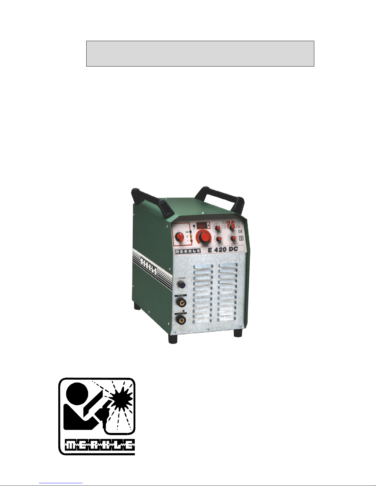
Operation Manual
MMA/Stick Elektrode Unit
Model E 420 DC
MERKLE
Schweißanlagen-Technik GmbH
Industriestraße 3
D-89359 Kötz
Tel.: (08221) 915-0
Fax: (08221) 915-40
www.merkle.de


Inhalt Seite
1 Accident prevention regulations 2
1.1 Safety instructions 2
2 Duty cycle 4
3 Instructions to avoid interferences due to electromagnetic influences EMC 4
4 Technical Data 6
4.1
MMA/Stick Electrode Welding Unit Model E 420 DC 6
5 Start Up 7
5.1 Installation of the Machine 7
5.2
Main Supply 7
5.3 Connection of the welding cables 7
5.4 Earth Lead (Work Cable) 8
5.5 Operation mode: TIG 8
5.6 Operation with the unit connected to a generator 8
5.7 Cable prolongations 8
5.8 Transport 8
6 Generalities of the welding unit Model E 420 DC 8
6.1 Cooling of the power modul 9
6.2 Electronics 9
6.3 Electrode Holder 9
6.4 TEDAC-System 9
7 Current Adjusting 9
8 Operation of the unit E 420 DC 11
9 Cleaning 12
10 Maintenance and Accident Prevention 12
11 Trouble Shooting 12
12 Partlist and wiring diagram 14
12.1 Partlist E 420 DC 14
12.2 Wiring diagram E 420 DC 15
1

Dear customer,
we wish to thank you for choosing a MERKLE welding machine. In doing so, you have
demonstrated to us the trust you place in our products.
With best wishes
MERKLE
Schweißanlagen Technik GmbH
1 Accident prevention regulations
The following accident prevention regulation is applied for welding with MMA welding
units, type E 420 DC:
VBG 15 / BGV D1* Welding, cutting and allied processes.
A copy of this regulation should be readily accessible in every welding shop. The stipulations
of this regulation are to be observed in the interests of safe and correct welding operation.
Available from the trade association responsible or
Carl Heymanns-Verlag, Luxemburger Strasse 449, 50939 Cologne.
1.1 Safety instructions
This unit is manufactured according to the requirements and stipulations of EN 60974.1 /
VDE 0544. The accident prevention regulations “Welding, cutting and allied processes”
(VBG 15 / BGV D1) of the trade association for precision engineering and electrical
engineering are as well valid.
1) In case of an accident, the welding unit must be disconnected from the mains
immediately.
2) If electrical contact voltages arise, switch off the unit immediately, disconnect it from
the mains and proceed to inspection by a qualified electrician or by our Service
Department.
3) Before opening the unit, disconnect it from the mains supply.
4) Repair work may only be carried out by a skilled electrician or by our Service
Department.
5) Before the unit is put to operation, check it visually, as well as the torch and all cables
and connectors regarding possible external damages.
6) Personal protective equipment in accordance with DIN EN 175, DIN EN 379 and
DIN EN 169.
During the work, the welder’s body must be completely protected against radiation
and burns by means of protective clothing and face protection. Long gloves, aprons
and welding shields with welding filters conforming to DIN EN 470-1 and BGR 189
2

must be worn. Synthetic clothing are excluded. Shoes must be closed, not opened (due
to spatters). If necessary, protective headwear must be worn (e.g. for overhead
welding). If cover glasses are used, these must be in accordance with the norms
specified above. As additional protection for the eyes against UV radiation, safety
goggles with side shields and corresponding face protection in accordance with
BGR 192 and BGI 553 must be worn.
Accident prevention regulation BGV D1 § 27 stipulates that it is the responsibility of
the employer to provide suitable personal protective equipment, while § 28 stipulates
that it is the responsibility of the insured to wear suitable clothing.
7) Protection when welding under increased electrical risks
Welding rectifiers and welding power sources which can optionally be used for either
direct or alternating current must be marked "S" in accordance with EN 60974-1 and
BGI 534.
Use insulating materials to protect you against contact with electrically conductive
parts and damp floors. Wear dry, undamaged work clothing, long gloves and footwear
with rubber soles. Ventilate rooms, install extraction systems if required, and wear
respiratory protective equipment if necessary (see Procedural instructions BGV D1
§ 27 and BGI 533, Section 5).
8) In order to prevent stray currents and the effects thereof (e.g. destruction of electrical
protective ground conductors), the welding return cable (workpiece cable) must be
connected directly to the workpiece to be welded or to the table (e.g. welding table,
grid-type welding table, workbench) supporting the workpiece (see BGV D1 § 20).
When installing the ground connection, assure that there is a good electrical contact
(remove rust, paint, etc.).
9) During welding pauses, the welding torch is to be laid down on an insulated surface or
hung up in such a way that it is not in contact with the workpiece and its support
connected to the welding power source (see § 20 BGV D1).
In the case of longer work pauses, the welding unit must be switched off and the gas
cylinder valve must be closed.
10) The shielding gas cylinder must always be protected against tumbling downing using a
safety chain.
11) Under no circumstances the unit may be put into operation while it is opened
(e.g. for repair work). Apart from the safety regulations, sufficient cooling of the
electrical components provided by the fan cannot be guaranteed.
12) In accordance with BGV D1 § 5, people in the vicinity of the arc must also be
informed of the hazards and protected against them. Safety partitions (“welding safety
curtains”) must be erected in accordance with DIN EN 1598.
13) No welding work may be carried out on containers in which gases, fuels, mineral oils
or similar substances have been stored even if they have been empty for a long
time (risk of explosion). See § 31 of accident prevention regulation BGV D1.
14) Welds which will be subjected to high loads and which need to meet specific safety
requirements may only be carried out by specially trained and qualified welders.
3

15) Never bring the torch close to your face.
16) In areas at particularly high risk of fire, the welder must obtain a welding permit and
have this on his person throughout the duration of the welding work. On completion of
welding, a fire-guard must be delegated to ensure fire protection.
17) Ventilation measures must be applied in accordance with BGI 553, Section 9.
18) The hazard to eyesight must be indicated by means of a sign at the work site
"CAUTION! Do not look into the arc!".
2 Duty cycle
The duty cylce measurings have been carried out in accordance with
EN 60974-1 / VDE 0544 (10 min working period).
60% duty cycle means:
After a 6 min. welding period a 4 min welding pause must be respected. The electrical
components are thermally protected against overheating.
3 Instructions to avoid interferences due to electromagnetic influences
EMC
The welding unit has been manufactured in accordance with the requirements of guideline
EN 50199 regarding electromagnetic compatibility. It is nonetheless the responsibility of the
user to ensure that the welding equipment is installed and operated in accordance with the
manufacturer’s instructions. If electromagnetic interference is detected, it is the responsibility
of the user of the welding equipment to find a solution with the technical assistance of the
manufacturer. In some cases, it may be sufficient simply to ground the welding current
circuit. In other cases, it may be necessary to build a complete shield for the welding power
source and workpiece using the input filters. In all cases, electromagnetic interference must be
reduced to avoid any possible malfunctions.
Note:
For safety reasons, the welding current circuit may or may not be grounded. No
modifications may be made to the grounding without the approval of an expert who is able to
determine whether the changes might increase the risk of accidents, e.g. by allowing parallel
welding current return paths which could destroy the ground conductors of other equipment.
Further instructions are contained in TEC 974-XX "Arc welding equipment – installation and
use".
a) Evaluation of the installation site
Before installing the welding equipment, the user must evaluate potential
electromagnetic problems in the vicinity. The following must be taken into
consideration:
Other power cables, control cables, signal and telecommunication cables above, below
and next to the welding equipment
Radio and television transmitters and receivers
Computers and other control devices
The health of people in the vicinity, e.g. use of heart pacemaker and hearing aids
Calibration and measuring equipment
Interference immunity of other devices in the vicinity. The user must ensure the
electromagnetic compatibility of other devices used in the vicinity. This may require
additional safety measures.
4

b) Procedures to reduce emitted interference
1) Mains supply
Welding equipment is to be connected to the mains in compliance with the
recommendations of the manufacturer. If interference occurs, it may be necessary to
take additional precautions, e.g. filters for the mains connection. Make sure that the
power cable of welding equipment is installed in a fixed position shielded by means of
a metal conduit or similar. The entire length of the shield must be electrically
connected. The shield must be connected to the welding power source in the way to
obtain a good electrical contact between the metal conduit and the housing of the
welding unit.
2) Maintenance of the welding equipment
Welding equipment must be maintained regularly in accordance with the
recommendations of the manufacturer. All access and service doors and covers must
be closed and fastened securely when the welding equipment is in operation. No
modifications whatsoever may be made to welding equipment with the exception of
modifications and adjustments specified in the manufacturer’s operating instructions.
3) Welding cables
Welding cables should be kept as short as possible and routed close together on or
near the floor.
4) Equipotential bonding
It is advisable to interconnect all metallic parts in and next to the welding equipment.
Metallic parts connected to the workpiece can, however, increase the risk of the
welder receiving an electric shock by touching these metallic parts and the electrode
simultaneously. The welder must be electrically insulated against all these connected
metallic parts.
5) Grounding the workpiece
If the workpiece is not connected to the ground for electrical safety reasons, or due to
the size and position of the workpiece, e.g. steel structure or outer wall of a ship,
grounding the workpiece may in some cases, but not all, reduce emitted interference. It
must be ensured that grounding the workpiece will not increase the risk of accidents
for the user and cannot cause the destruction of other electrical equipment. If
necessary, the grounding of the workpiece must be carried out by means of a direct
connection to the workpiece. In countries where a direct connection is prohibited, the
connection must be made by means of suitable reactors, selected in accordance with
national regulations.
6) Shielding
Selective shielding of other cables and devices in the vicinity can reduce interference
problems. For special applications, it may be worth considering shielding the entire
welding system.
5

4 Technical Data
4.1 MMA/Stick Electrode Welding Unit Model E 420 DC
Primary:
Supply: 3 x 400 / 415V
Frequency: 50-60 Hz
Cont. power: 11,8 kVA
Cont. current: 17 A
Max. current: 29 A
Cos phi: 0,9
Secondary:
Open circuit voltage: 80 V
Welding voltage: 20-37 V
Welding current: 5-420 A
Duty cycle 40 % (10 min.) 420 A
Duty cycle 60 % (10 min.) 350 A
Duty cycle 100 % 280 A (40°C)
Protection class: IP 23
Insulation class: H
Cooling: AF
Main switch: 3-phase
Potentiometer: welding current
Potentiometer: arc force
Potentiometer: hotstart time
Potentiometer: hotstart current
Socket: remote control
Operation modes: switch: 6-step:
Stick electrode, positive
Stick electrode, negative
Stick electrode, remote control
Stick electrode, TEDAC
Digital read out: welding current, with Hold function
and with pre-indication
Control lamp: mains ON,
thermic protection,
failure,
Hold
Power source: inverter (IGBT)
Functions: hotstart, antistick,
arc force, TIG liftarc
stabilisation: ± 10 % mains voltage fluctuation
Norm: EN 60974-1 "S" / CE
Socket 70 mm²: workpiece cable
Socket 70 mm²: Electrod cable with holder
Power supply cable: 4 x 4 mm², 5 m long
Weight: 58 kgs
Dimensions l x w x h: 605 x 430 x 630 mm
6

Standard accessories:
Description Part No.
Earth lead 70 mm², 4 m long 022.1.0408
with plug and earth clamp
Electrode welding cable 70 mm², 5 m 022.1.0449
incl. plug and electrode holder
Accessories:
Polarity change, installed inside 013.0.1075
the welding unit
Hand remote control, incl. Polarity 019.0.3549
switch, cable 6 m and plug
TEDAC operation, installed inside 012.0.0725
the welding unit
Hand shield with TEDAC function, 012.0.0750
polarity change, 5 m cable and plug
Welding cable, 70 mm², black, per m 009.0.0400
Accessories for TIG welding:
Regulator argon/CO2, single stage 012.0.0300
TIG hand welding torch WHL 240-H 013.6.0120
with manual gas valve, 8 m
5 Start Up
5.1 Installation of the Machine
Place the machine at least 0.80 m from a wall etc. to guarantee the cooling air can go
through the unit. The room temperature should not exceed 40°C.
The room were the unit is placed should have a low degree of humidity
(max. 50 % at 40°C, max. 90 % at 20° C).
The unit has passed the quality control in accordance with IP 21. When operating in places
with high humidity, an additionad filter must be mounted (IP 23).
The air in the surroundings must be free from extreme quantities of dust, free from acides and
corrosive gases etc. Otherwise use air filters .
5.2 Main Supply
The main supply must be connected by a trained person. The main supply voltage is displayed
on the front or rear panel of the machine. A connection to ground (GND) must be done.
5.3 Connection of the welding cables
Operation mode: electrode
Choose the correct polarity according to the type of electrode by plugging in the work piece
cable and the cable of the electrode. Units with the mounted option “polarity switching“ do
not need a change of the welding cables. The polarity is switched at the TEDAC-handshield.
7

5.4 Earth Lead (Work Cable)
The earth lead must have an excellent ground. The clamp should be attached to a clean, paint
and rust free area on the work piece or on the welding table.
5.5 Operation mode: TIG
Plug in the TIG torch and the work piece cable to the plus pole bush. Connect the gas hose of
the TIG torch to the gas regulator. Adjust the gas quantity as desired and ignite the arc by
making a contact between torch, electrode and the workpiece (Lift Arc)
5.6 Operation with the unit connected to a generator
Consider the following comments:
The power of the generator must be at least 10% higher than the power of the welding
unit.
The generator´s outcoming voltage must be stabilized in the no load voltage mode as well.
Due to possible peaks of the generator when switching ON, the welding unit should be
switched ON afterwards.
5.7 Cable prolongations
Only use non damaged prolongation cables with the correct sections.
Do not work with looped cables Overloading due to heat!
When using extremely long cables the welding output is reduced.
In this case encrease the sections of the cable.
5.8 Transport
If a transport by crane is required, the unit must be fixed at all lifting eyes.
6 Generalities of the welding unit Model E 420 DC
The welding unit E 420 DC is based on inverter technique and suitable for MMA/stick
electrode welding. Continuous setting of the welding current up to 420 A.
The unit can be characterized by numerous features:
inverter power source with continuous setting of the current 5-420 A
socket for remote control
digital read out with pre-display and hold-function
stick electrode operation:
1. Arc force:
increasing of the welding current in order
to avoid adherence of the electrode.
2. Hotstart function:
increasing of the start current to
assure a safe ignition.
3. Anti stick function:
In case of adherence of the electrode, the current
is switched off immediately. Re-ignition after separation
only is possible with a short retardation.
8

6.1 Cooling of the power modul
The fans which are cooling the power modul are switched on automatically as soon as the arc
is enlighted.
6.2 Electronics
The electronic is divided in to 3 sections:
Display, selection of the logic and the operation mode
Adjusting and program parameters
Supervision of the temperature, fan control
6.3 Electrode Holder
Only use electrode holders with a proper insulation and a good contact with the electrode.
6.4 TEDAC-System
The TEDAC-System offers the possibility to adjust the energy from min. to max. by means of
a slide switch (mounted at the hand shield ). The poti „energy“ is limiting the range of the
welding current.
The multi-coloured LED at the handle inside the shield shows the actual setting of the
welding current.
red - max. energy
green - min. energy
7 Current Adjusting
The welding current depends on the stick electrode and the diameter
Formula: ca. 40-50 A/diameter of electrode in mm
Diameter of electrode 2,0 2,5 3,25 4,0 5,0 6,0
(mm)
Current (A) 40-80 60-100 90-150 140-180 170-240 250-300
For further details see instructions of the relative electrode you are using.
9

Front panel of the E 420 DC
10
SCHWEISSTROM
welding current
HOTSTART - STROM
current
STROMNACHREGELUNG
arc force
HOTSTART - ZEIT
timer
TEDAC
HOLD
0
1
2
3
4
5
6
7
8
9
10
20
40
60
80
100
120
140
160
180
200
220
240
260
280
300
320
340
360
380
400
420
A %
120
130
140
150
160
170
180
190
200
s
0.2
0.4
0.6
0.8
1.0
1.2
0
5 6 7 8 9 10 11 12 13
4
3
2
1
14

8 Operation of the unit E 420 DC
1. Socket – Electrode cable with holder
2. Socket – Workpiece cable
3. 10-pole socket
for remote control or the setting by the TEDAC-System the welding shield
4. Main Switch
5. LED failure: “overheating” – unit is dirty or the duty cycle has been passed,
or “over voltage”- supply voltage higher than 440 VAC,
or “under voltage”- supply voltage lower than 360 VAC
6. LED (yellow) thermal protection
7. LED (green) mains ON
8. Potentiometer welding current 5A...420A
9. LED (green) Hold
10. Digital read-out for the welding current with HOLD function
It shows the welding current during the welding process. After the welding process the
HOLD-LED is enlighted and shows the last value of the welding current.
(no pre-indication of the real welding current)
11. Potentiometer HOTSTART-current 115%...200% of the potentiometer current
12. Potentiometer HOTSTART-time 0.01s...1,2s
13. Selector welding operation mode
13.1 electrode plus-pole: plug in the cable with the electrode holder to the bush electrode,
Potentiometer current at the unit works
13.2 electrode minus-pole: plug in the cable with the electrode holder to the bush electrode,
Potentiometer current at the unit works
13.3 Electrode: Set of the polarity by the remote control,
Potentiometer at the remote control works. The potentiometer current at the
machineis limitating the max. value
13.4 Electrode: the polarity can as well be set by the switch at the TEDAC-shield
TEDAC-slide switch works (increasing or reducing the energy), The poti current is
limitating the max. value
13.5 TIG minus-pole at the torch (bush-work piece): Liftarc, (no torch trigger),the poti
current at the machine works, Hotstart andArc Force are out of function
13.6 TIG, minus-pole at the torch (bush- work piece): Liftarc, (no torch trigger),
manual remote control activated, the poti current is limitating the max. value
Hotstart and Arc Force are out of function
11

14. Potentiometer ARC-FORCE 1..10 (250%)
avoids adherence of the electrode on the work piece:
Rutil electrode: setting of the Arc Force between 1..3
Basic electrode setting of the Arc Force to 5
Cellulosic- electrode: setting of the Arc Force to 10
9 Cleaning
IMPORTANT:
!!! Before opening the machine, disconnect it from mains !!!
Open the side covers. Remove dust from all parts of the machine.
Blow away the dust at the pcbs of the inverter withcompressed air –reduced pressure
(appr. 0,5 – 1 bar). We recommend to clean the unit in regular periods.
10 Maintenance and Accident Prevention
The maintenance of the welding machine consists of a regular cleaning and inspection. It
depends on the environment of the working area and the working hours.
The machine should be cleaned in regular intervals to guarantee a proper operation. The
length of the cleaning interval depends on the operation time, surrounding atmosphere etc.
ATTENTION: Before opening the welding machine, make sure
that it is disconnected from the mains supply. Wait for
components to be sufficiently cooled down !
Wait until the capacitors are discharged (appr. 3 min.)!
11 Trouble Shooting
LED "mains ON" (green) does not go on after switching on the machine
Check main supply
Check main fuses
LED "failure" (red) is on
Supply voltage too low or too high
LED "failure" (red) goes on for a short time
Safety cut off device for primary current protection is activated:
Switch off and after aprox. 3 s switch on again.
LED "Temp. protection" (yellow) and LED "failure" (red) are on
unit is dirty or the duty cycle has been passed,
Too high temperature at the transformer or IGBT-body:
Let machine cool down.
12

Machine has no or too low welding current
Check main supply of the welding unit (fuses)
Bad or no contact of the welding leads
Poor welding quality
wrong adjustment of voltage trim
Oxydated material
13

12 Partlist and wiring diagram
12.1 Partlist E 420 DC
electr. Description part no.
A1 Pc-board ME-I-PG-1.0 003.0.0001
A2 Pc-board ME-I-PI-1.0 003.0.0002
A3 Pc-board Pc-board ME-I-SD-1.1B 003.0.0003
A4 Pc-board Pc-board ME-EMV-3.1 102281
A5 Pc-board ME-NF400/2.5 102279
A7 Pc-board ME-I-RC-1.1 003.0.0004
A9 LEM-converter 010.0.1615
A11 Pc-board ME-ELREG-1.4 003.0.0027
A12 Pc-board ME-DISP-1.4 003.0.0044
A13 Pc-board ME-ELTEDAC-1.4 (Option) 003.0.0047
A15 Pc-board ME-UMPOL-1.4 (Option) 003.0.0050
C1 capacitor 0,1 µF/1000V 001.0.0415
C2 capacitor 0,1 µF/1000V 001.0.0415
C3 capacitor 5 nF/250V 003.0.5093
C4 capacitor 0,1 µF/1000V 001.0.0415
C5 capacitor 5 nF/250V 003.0.5093
A1/F1 fuse 0,2 A, slow at Pc-board ME-I-PG-1.0
A1/F1 fuse 0,2 A, slow at Pc-board ME-I-PG-1.0
A1/F3 fuse 0,2 A, slow at Pc-board ME-I-PG-1.0
F4 fuse 4 A, slow control transformer prim. 400 V 00301251
F5 fuse 4 A, slow control transformer prim. 400 V 00301251
F6 fuse 10 A slow control transformer sec. 42 V 00301199
F7 fuse 1 A slow control transformer sec. 42 V 00301212
F8 Termical switch 80°C opend 00100406
K1 contactor EH90-30-22 (GJD8230310R0103) (Option) 020.1.1510
K2 contactor EH90-30-22 (GJD8230310R0103) (Option) 020.1.1510
K3 contactor EH90-30-22 (GJD8230310R0103) (Option) 020.1.1510
K4 contactor EH90-30-22 (GJD8230310R0103) (Option) 020.1.1510
L1 choke (ferrit) 001.0.1992
M1 fan 230 V-AC at the Inverter 001.0.1323
M2 fan 230 V-AC at the Inverter 001.0.1323
Q1 main switch HLT 40 001.0.0014
R1 resistor 0,02 Ω/50W 030.0.4580
R2 resistor 330 Ω/50W 030.0.4583
R3 resistor 330 Ω/50W 030.0.4583
14

electr. Description part no.
R10 resistor 330 Ω/50W 030.0.4583
R15 NTC- resistor at the cooling body to IGBT 47 kΩ 010.0.1933
R17 resistor 39 Ω/50W 030.0.4584
T1 Ferrit- main transformer 001.0.1990
T2 control transformer MT400-500 003.0.0240
T3 converter 020.1.1124
T4 converter 020.1.1124
V1 rectifier-modul 001.0.0287
V2 rectifier-modul 001.0.0287
V3 rectifier-modul 001.0.0287
V4 rectifier-modul 001.0.0287
V5 rectifier-modul 001.0.0287
V6 rectifier-modul 001.0.0287
X1 bush 70/95mm² 500A 00101102
X2 bush 70/95mm² 500A 00101102
10-pol. socket for remote control 02110386
(Option remote control or
Hand shield with TEDAC function)
10-pol. plug (acessories) 02110383
strain relief (acessories) 02110388
12.2 Wiring diagram E 420 DC
15

16

17

18

19

20

21

EU-Conformity Attestation
EU – Conformity Attestation
Description of the unit: MMA/Stick Electrode Unit
Model: E 420 DC
The above mentionned unit complies with the following European Regulations:
EU-Low Voltage Regulation 73/23/EWG
EU-Electromagnetic Compatibility 89/336/EWG
In case of any modifications, incorrect repairs not exclusively authorized by Merkle, this
attestation looses its valdity.
Applied norms EN 60974 - 1 / IEC 974 - 1 / VDE 0544 part 1
EN 60204 - 1 / IEC 204 - 1 / VDE 0113 part 1
EN 50199
Kötz, October 15th, 1996
Wilhelm Merkle, Generalmanager
Merkle Schweißanlagen-Technik GmbH
22

Notes
:
23

M E R K L E
Schweißanlagen-Technik GmbH
MERKLE
Schweißanlagen-Technik GmbH
Industriestraße 3
D-89359 Kötz
Tel.: (08221) 915-0
Fax: (08221) 915-40
www.merkle.de
1. Edition 2003 July 14th, 2003
Changes reserved.
24
 Loading...