

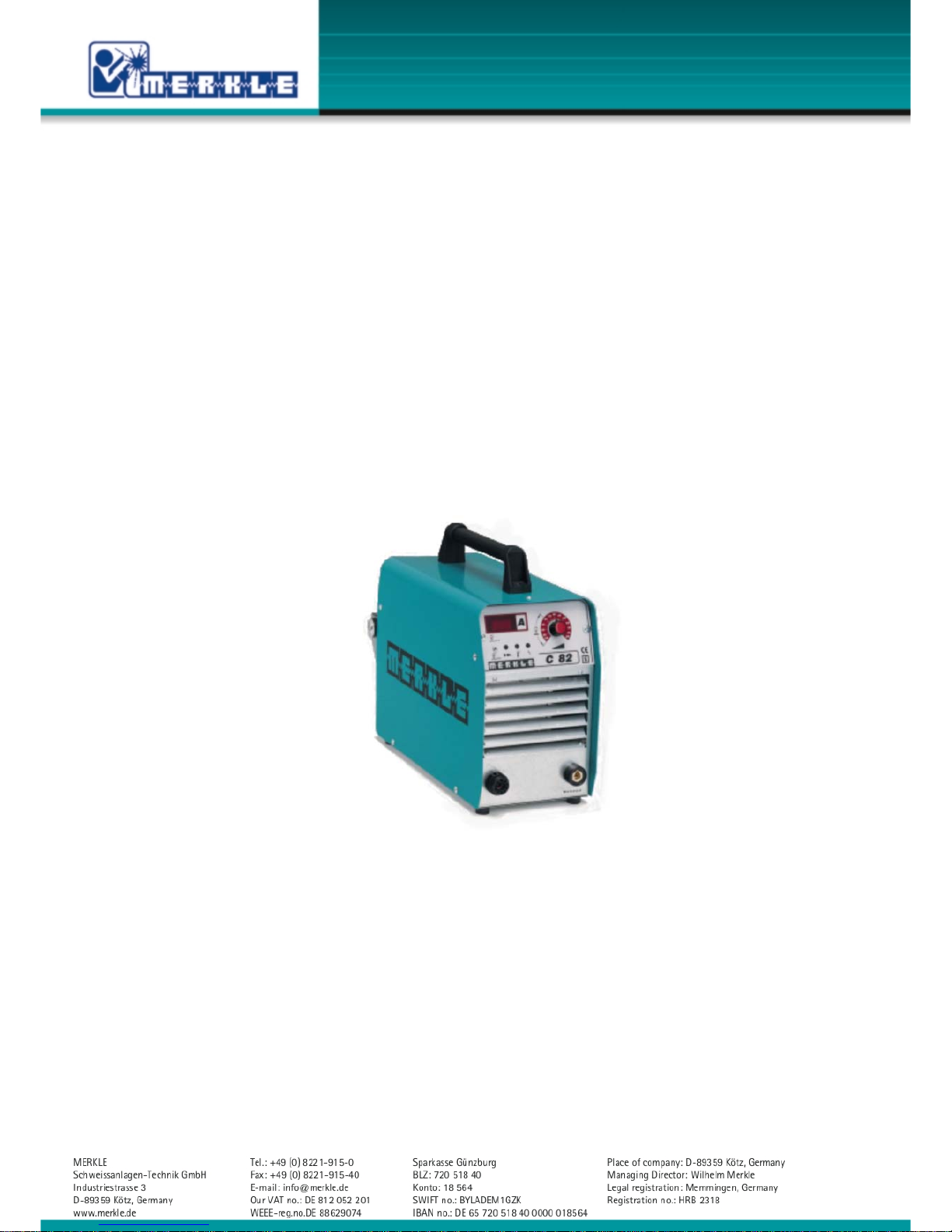
Operation Manual
Plasma cutting unit
Model C82

1
Content page
1. Security indications before introduction 2
2. Accident prevention regulations 2
1.1
Safety instructions
2
1.2
Additional Safty Precautions for Plasma Cutting
4
3. Duty cycle 4
4. Instructions to avoid interferences due to electromagnetic influences EMC 4
5. Technical data plasma cutting unit C 82 6
6. Start up 7
1.3
Installation of the Machine
7
1.4
Welding Torch
7
1.5
Earth Lead (Work Cable)
7
1.6
Compressed air
7
7. Operation of the unit 9
8. Maintenance 10
9. Trouble Shooting 10
1.7
Machine does not operate after switching on the main switch
10
1.8
Machine does not react on the torch switch
10
1.9
Pilot arc does not start
10
1.10 No or too low cutting current
10
1.11 Over temperature
10
10. Plasma hand cutting torch PR 81 11
11. Spare parts and wiring diagram 15
1.12 Spare part list model: C 82
15
1.13 Wiring diagram C 82
16
12. EU-Conformity Attestation C 82 20

2
1. Security indications before introduction
The unit device is built after the recognized standards. Safe works are nevertheless only possible
if you read the operating instructions and the safety regulations contained in it entirely and
obey strictly. Install yourselves by trained staff of our establishments or appointed dealers.
2. Accident prevention regulations
The following accident prevention regulation is applied for cutting unit, model C 82
BGV D1 (earlier VBG 15) * Welding, cutting and allied processes.
A copy of this regulation should be readily accessible in every welding shop. The stipulations of
this regulation are to be observed in the interests of safe and correct welding operation.
* Available from the trade association responsible or
Carl Heymanns-Verlag, Luxemburger Strasse 449, 50939 Cologne.
1.1 Safety instructions
This unit is manufactured according to the requirements and stipulations of EN 60974.1 / VDE
0544 part 1. BGV D1 (earlier VBG 15) of the trade association for precision engineering and
electrical engineering are as well valid.
1) In case of an accident, the cutting unit must be disconnected from the mains
immediately.
2) If electrical contact voltages arise, switch off the unit immediately, disconnect it from
the mains and proceed to inspection by a qualified electrician or by our Service
Department.
3) Before opening the unit, disconnect it from the mains supply.
4) Repair work may only be carried out by a skilled electrician or by our Service
Department.
5) Before the unit is put to operation, check it visually, as well as the torch and all cables
and connectors regarding possible external damages.
6) Personal protective equipment in accordance with DIN EN 175, DIN EN 379 and
DIN EN 169.
During the work, the welder’s body must be completely protected against radiation and
burns by means of protective clothing and face protection. Long gloves, aprons and
welding shields with welding filters conforming to DIN EN 470-1 and BGR 189
must be worn.
Synthetic clothing are excluded. Shoes must be closed, not opened (due to spatters). If
necessary, protective headwear must be worn (e.g. for overhead welding). If cover
glasses are used, these must be in accordance with the norms specified above.
As additional protection for the eyes against UV radiation, safety goggles with side
shields and corresponding face protection in accordance with BGR 192 and BGI 553
must be worn.
Accident prevention regulation BGV D1 § 27 stipulates that it is the responsibility of the
employer to provide suitable personal protective equipment, while § 28 stipulates that it
is the responsibility of the insured to wear suitable clothing.

3
7) Protection when welding under increased electrical risks
Welding rectifiers and welding power sources which can optionally be used for either
direct or alternating current must be marked "S" in accordance with EN 60974-1 and
BGI 534.
Use insulating materials to protect you against contact with electrically conductive parts
and damp floors. Wear dry, undamaged work clothing, long gloves and footwear with
rubber soles. Ventilate rooms, install extraction systems if required, and wear respiratory
protective equipment if necessary (see Procedural instructions BGV D1 § 27 and BGI 533,
Section 5).
8) In order to prevent stray currents and the effects thereof (e.g. destruction of electrical
protective ground conductors), the welding return cable (workpiece cable) must be
connected directly to the workpiece to be welded or to the table (e.g. welding table,
grid-type welding table, workbench) supporting the workpiece (see BGV D1 § 20). When
installing the ground connection, assure that there is a good electrical contact (remove
rust, paint, etc.).
9) During welding pauses, the welding torch is to be laid down on an insulated surface or
hung up in such a way that it is not in contact with the workpiece and its support
connected to the welding power source (see § 20 BGV D1).
In the case of longer work pauses, the welding unit must be switched off and the gas
cylinder valve must be closed.
10) The shielding gas cylinder must always be protected against tumbling downing using a
safety chain.
11) Under no circumstances the unit may be put into operation while it is opened
(e.g. for repair work). Apart from the safety regulations, sufficient cooling of the
electrical components provided by the fan cannot be guaranteed.
12) In accordance with BGV D1 § 5, people in the vicinity of the arc must also be informed
of the hazards and protected against them. Safety partitions (“welding safety curtains”)
must be erected in accordance with DIN EN 1598.
13) No welding work may be carried out on containers in which gases, fuels, mineral oils or
similar substances have been stored even if they have been empty for a long time
(risk of explosion). See § 31 of accident prevention regulation BGV D1.
14) Welds which will be subjected to high loads and which need to meet specific safety
requirements may only be carried out by specially trained and qualified welders.
15) Never bring the torch close to your face.
16) In areas at particularly high risk of fire, the welder must obtain a welding permit and
have this on his person throughout the duration of the welding work. On completion of
welding, a fire-guard must be delegated to ensure fire protection.
17) Ventilation measures must be applied in accordance with BGI 553, Section 9.
18) The hazard to eyesight must be indicated by means of a sign at the work site "CAUTION!
Do not look into the arc!".

4
1.2 Additional Safty Precautions for Plasma Cutting
ATTENTION ! Disconnect plasma cutting unit from mains supply before opening the machine!
Switch off machine before exchanging of cutting nozzle, electrode and outer nozzle.
Protect the cutting torch against humidity.
Immediately exchange faulty parts at the torch neck or at the hose assembly.
3. Duty cycle
The duty cycle is measured at temperature of 40°C and a 10 minutes period. At lower
temperatures the duty cycle is higher
4. Instructions to avoid interferences due to electromagnetic influences EMC
The cutting unit has been manufactured in accordance with the requirements of guideline
EN 60974-10 regarding electromagnetic compatibility. It is nonetheless the responsibility of the
user to ensure that the welding equipment is installed and operated in accordance with the
manufacturer’s instructions. If electromagnetic interference is detected, it is the responsibility of
the user of the welding equipment to find a solution with the technical assistance of the
manufacturer. In some cases, it may be sufficient simply to ground the welding current circuit.
In other cases, it may be necessary to build a complete shield for the welding power source and
workpiece using the input filters. In all cases, electromagnetic interference must be reduced to
avoid any possible malfunctions.
Note: For safety reasons, the welding current circuit may or may not be grounded. No
modifications may be made to the grounding without the approval of an expert who is able to
determine whether the changes might increase the risk of accidents, e.g. by allowing parallel
welding current return paths which could destroy the ground conductors of other equipment.
Further instructions are contained in TEC 974-XX "Arc welding equipment – installation and
use".
a) Evaluation of the installation site
Before installing the welding equipment, the user must evaluate potential
electromagnetic problems in the vicinity. The following must be taken into
consideration:
Other power cables, control cables, signal and telecommunication cables above, below
and next to the welding equipment
Radio and television transmitters and receivers
Computers and other control devices
The health of people in the vicinity, e.g. use of heart pacemaker and hearing aids
Calibration and measuring equipment
Interference immunity of other devices in the vicinity. The user must ensure the
electromagnetic compatibility of other devices used in the vicinity. This may require
additional safety measures.

5
b) Procedures to reduce emitted interference
1) Mains supply
Welding equipment is to be connected to the mains in compliance with the
recommendations of the manufacturer. If interference occurs, it may be necessary to
take additional precautions, e.g. filters for the mains connection. Make sure that the
power cable of welding equipment is installed in a fixed position shielded by means of a
metal conduit or similar. The entire length of the shield must be electrically connected.
The shield must be connected to the welding power source in the way to obtain a good
electrical contact between the metal conduit and the housing of the welding unit.
2) Maintenance of the welding equipment
Welding equipment must be maintained regularly in accordance with the
recommendations of the manufacturer. All access and service doors and covers must be
closed and fastened securely when the welding equipment is in operation. No
modifications whatsoever may be made to welding equipment with the exception of
modifications and adjustments specified in the manufacturer’s operating instructions.
3) Welding cables
Welding cables should be kept as short as possible and routed close together on or near
the floor.
4) Equipotential bonding
It is advisable to interconnect all metallic parts in and next to the welding equipment.
Metallic parts connected to the workpiece can, however, increase the risk of the welder
receiving an electric shock by touching these metallic parts and the electrode
simultaneously. The welder must be electrically insulated against all these connected
metallic parts.
5) Grounding the workpiece
If the workpiece is not connected to the ground for electrical safety reasons, or due to
the size and position of the workpiece, e.g. steel structure or outer wall of a ship,
grounding the workpiece may in some cases, but not all, reduce emitted interference. It
must be ensured that grounding the workpiece will not increase the risk of accidents for
the user and cannot cause the destruction of other electrical equipment. If necessary,
the grounding of the workpiece must be carried out by means of a direct connection to
the workpiece. In countries where a direct connection is prohibited, the connection must
be made by means of suitable reactors, selected in accordance with national regulations.
6) Shielding
Selective shielding of other cables and devices in the vicinity can reduce interference
problems. For special applications, it may be worth considering shielding the entire
welding system.

6
5. Technical data plasma cutting unit C 82
Primary:
Supply: 3 x 380-440 V (200-240 V)
Frequency: 50 - 60 Hz
Continuous power: 11.5 kVA
Continuous current: 16.5 A
Max. current: 21 A
cos phi: 0.99
Secondary:
Open circuit voltage: 280 V
Welding voltage: 90-120 V
Cutting current: 20-80 A
Duty Cycle 35 %: 80 A (10 min.)
Duty Cycle 100 %: 40 A (40°C)
Protection: IP 23
Insulation class: H
Cooling: AF
Main switch: 3-phase
Energy control: continuous adjustable
LEDs: mains on,
failure,
temp. protection,
Digital display: cutting current (option)
Switch: cutting of metal mats
Cutting gas: compressed air
Pressure indicator: regulator at the rear
Pilot arc: safety cut-off,
timer controlled
Air pre-flow time: installed
Air post-flow time: automatic controlled
depending on cutting time
Valve: continuous adjustable
gas pressure
Fan: automatic controll
Power source: inverter
Norm: EN 60974-1 "S" / CE
Torch cooling: compressed air
Torch connection: plasma Euro connector
Weight: 26 kg
Dimensions l x w x h: 535 x 230 x 465 mm
Power supply cable: 4 x 2.5 mm², 5 m long
Air supply connector: quick locking
Socket 50 mm²: earth lead
Handle: on top of the unit
Accessories:
Earth lead 35 mm², 4 m long 022.1.0401
with plug and earth clamp

7
6. Start up
1.3 Installation of the Machine
If the unit is brought from cold ambient temperatures into a tempered room, for example
due to transportation or from unheated storage depots, it must be adapted before being put
to operation a certain time according to the temperature difference onto the ambient
temperature.
Place the machine at least 0.80 m from a wall etc. to guarantee the cooling air can go
through the unit. The room temperature should not exceed 40°C .
1.4 Welding Torch
Attach the hose assembly to the Euro-connector with the flange nut.
Switch off machine, when exchanging the cutting torch.
1.5 Earth Lead (Work Cable)
The earth lead must have an excellent ground. The clamp should be attached to a clean,
paint and rust free area on the workpiece or on the welding table.
1.6 Compressed air
Connect the air supply at the rear of the machine. The compressed air must be dry. Adjust an
air pressure at the valve at the rear of the machine to 6 bar. Reduce the air pressure to 4 bar
for a cutting current less than 30 A
If the air pressure falls below 2 bar, the machine will be switch of the cutting process and
the fairlure LED will go on.

8
6 Operation Panel
1
26
E 3175-21
34 5
Main switch at the rear of the machine
1 Switch: standard cutting mode/perforated sheed cutting
2 Display cutting current (option)
3 LED main on
4 LED temperature protection
5 LED failure (on when supply voltage too high or too low or when low gas pressure)
6 Potentiometer cutting current
Connection socket - positive polarity
The workpiece is connected here.
Plasma connection negative polarity
Connect the plasma cutting torch here.

9
7. Operation of the unit
Discription of the functions
Cutting: selector (1) down
Main switch ON, LED green for mains enlighted. Setting of the current according to the material
thickness by variable resistor.
switch on unit (main switch is located on the rear), green LED (mains on) will go on. Adjust
cutting current at the potentiometer according to the material thickness.
The arc will be started with a high frequency ignition generator. This activates the pilot arc,
which will start the cutting arc when the work piece is touched. If the pilot arc does not touch
the work piece within 2 s, it will be switched off. The torch trigger must be pressed down again
to re-start the pilot arc.
ATTENTION! Do not repeat the ignition process more often than necessary without cutting. The
cutting nozzle and the resistors for the pilotarc might be overloaded.
The torch nozzle can be touched down directly to the work piece after ignition when the cutting
current is not more than 40 A (operate with 4 bar gas pressure, use cutting nozzle 1.0/1.2 mm).
At cutting currents more than 40 A (operate with 6 bar gas pressure, use cutting nozzle 1.2 mm
up to 50 A, 1.4/1.6 mm up to 80 A), the outer nozzle must be equipped with a distance holder
and may not touch the work piece directly.
Start the cutting process at one edge of the work piece. Hold the torch neck 90° to the work
piece. Starting the cutting within the work piece, will result in a higher consumption of the
consumables.
The cutting arc will be switched off when the torch trigger is released or when the torch is
removed from the work piece. The air will run aprox. 2 s to cool down the torch after the cutting
process.
Cutting of perforated plates: selector (1) up
When arriving at the perforated part of the plate, the cutting arc is switched to pilotarc.
When the torch gets again in contact with the plate, the pilotarc is switched back to the cutting
arc.

10
8. Maintenance
The maintenance of the machine consists of a regular cleaning and inspection. The maintanace
intervals should depend on the use of the unit and on the workplace.
Attention: Disconnect mains supply before starting maintance work. Allow
machine to cool down before starting maintanace work.
Wait for the capacitors to be discharged (approx. 3 min)
Cutting torch PR 81
Attention: Before starting any maintainance work the torch must be disconnected from
the machine.
The coax-cable and the torch body should be checked regulary for visible damages.
9. Trouble Shooting
1.7 Machine does not operate after switching on the main switch
a) check main supply
b) check main fuses
1.8 Machine does not react on the torch switch
a) torch switch fuse
b) Check internal fuses
1.9 Pilot arc does not start
a) Check mains connection
b) Wear of electrode and/or cutting nozzle (exchange consumables)
1.10 No or too low cutting current
a) Bad or no connection of the workpiece
b) Hose assembly of the cutting torch is interrupted or partly interrupted
or a weak connection of the plasma torch connector
c) Wear of the electrode of cutting nozzle
1.11 Over temperature
Duty cycle is too high. Let the machine cool down.

11
10. Plasma hand cutting torch PR 81
Technical data:
Cutting current: max. 80 A/100 V = 8 kW
Duty cycle: 60 % (exept consumables)
Plasma carrier: compressed air
Gas pressure: 4.5 bar
Air consumption: aprox. 40 to 50 l/min.
Weight: 750 g/1 m H

12
Plasma Hand cutting torch model: PR 81 gas cooled

13
Plasma hand cutting torch model: PR 81 gas cooled
Plasma hand cutting torch 050.1.1315
Model PR 81, 8 m, plasma connector
Spare part list plasma cutting torch model: PR 81 gas cooled
Pos. description Part. No.
Spare parts and consumables:
1 Torch body PR 81 050.1.011
2 Plasma electrode PR 81 050.1.1077
3 Cutting tip 1.0 mm 050.1.1078
3.1 Cutting tip 1.2 mm 050.1.1068
3.2 Cutting tip 1.4 mm 050.1.1069
3.3 Cutting tip 1.6 mm 050.1.1067
4 Outer nozzle PR 81 050.1.0110
5 Stand off guide, PR 81 050.1.0125
For contact operation
(max. 40 A current):
7 Plasma electrode PR 81 050.1.0129
for contact operation
8 Cutting tip 1.0 mm, PR 81 050.1.0127
for contact operation
8.1 Cutting tip 1.2 mm, PR 81 050.1.0128
for contact operation
9 Handle, upper part (PR 81) 022.1.0691
10 Lower handle PR 81 022.1.0692
incl. trigger, spring
and contact metals
11 Trigger PR 81 022.1.0693
12 Safty trigger PR 81 022.1.0706
13 Contact plate (PR 81) 022.1.0696
14 Contact blade 022.1.0141
15 Spring 4.8 x 13, short 022.1.0695
16 Pressure reducing nozzle PR 81 012.0.1001
17 Spring for trigger 022.1.0130
18 Coax cable 8 m, PR 81 022.1.0504
20 Kinking protection at machine side 025.1.1300
MIG Euro connector (set 3 pieces)
21 Euro adapter nut 025.1.0300
22 Plasma central connector, torch 025.1.1691
side, 7-pol. plug
23 Kinking protection, at torch side 022.1.0694

14
Circular cutting equipment PR 81 050.1.0131
with compass tip and magnet holder
Guide carriage 050.1.0132
25 Ring 050.1.0985
26 Turning ring PR 81 050.1.0130
27 Fastening ring 090.1.1631
28 Wheel for circular cutting 050.1.1045
equipment PR 81/121
29 Fastening screw for wheels 050.1.0988
30 Radius bar 050.1.1046
31 Free centering pin 050.1.1049
32 Cross piece 050.1.1048
33 Magnet FG 50 IG 050.1.1047
34 Knurl screw 050.1.1050

15
11. Spare parts and wiring diagram
1.12 Spare part list model: C 82
electr. description part. No.
-A1 pc board ME-I4-PI-1.3 107350
-A2 pc board ME-EMV-3.1 102281
-A3 pc board ME-I4-SD 2.1 107360
-A4 pc board ME-I4-PLRC-1.0 110474
-A5 ignition generator SIG 3.7 02011607
-A6 pc board ME-I4-PLF-1.1 109820
-A7 pc board ME-BT-2.1 00300184
-A8 LEM current converter HTA 400 S 01001615
-A9 pc board ME-MAG-7/DIS-1.1 109824
-A13 pc board ME-I4-GT-1.0 / A.B.-S3 107346
-A14 pc board ME-I4-GT-1.0 / A.B.-S1 107343
-A15 pc board ME-I4-GT-1.0 / C.D.-S4 107348
-A16 pc board ME-I4-GT-1.0 / C.D.-S2 107344
-C1 capacitor 0,47 µF/630V 101981
-F1 fuse 4 A slow at control transformer 00301251
-F2 fuse 4 A slow at control transformer 00301251
-F3 fuse 1 A slow at control transformer 00301212
-F4 fuse 10 A slow at control transformer 00301199
-F5 fuse 1 A slow at control transformer 00301212
-F6 temperatur switch 80°C opener 00100406
-F7 manometric switch 2,2 bar 004.0.0203
-K1 contactor A12 – 42V 00100302
-L1 choke 107358
-L2 HF-choke 108130
-M1 fan 230V/AC 00101323
-Q1 main switch NLT 40/3ZM 00100020
-R1
resistor 3,3 k-50 W
110472
-R2
resistor 3,3 k-50 W
110472
-R3
resistor 3,3 k-50 W
110472
-R4
resistor 3,3 k-50 W
110472
-S1 selector hand- automatic (option) 00300900
-T1 main transformer with choke and ferrit core 107356
ferrit ring R34 (Tr.-prim.) 02011672

16
electr. description part no.
-T2 control transformer 00300243
-T3 current converter 02011124
-V1 thyrister modul 00100286
-V2 rectifier primary 107340
-V3 FET-modul 107338
-V4 FET-modul 107338
-V5 FET-modul 107338
-V6 FET-modul 107338
-V7 FET-modul 107338
-V8 FET-modul 107338
-V9 FET-modul 107338
-V10 FET-modul 107338
-V11 secondary rectifier 110050
-V12 secondary rectifier 110050
-V13 secondary rectifier 110050
-V14 secondary rectifier 110050
-V15 secondary rectifier 110050
-X1 EURO-connector plasma- torch 02511690
-X2 socket 35/50 mm² 00101101
-X4 socket 10pol remote control 02110382
plug (accessories) 02110383
srenght member (accessories) 02110388
-X5 connector 6-pol. Body (option connection machine) 01500101
connector 6-pol. Plug (option connection machine) 01500102
-Y1 valve 42V/AC 00201602
crimp contakt (accessories) 016.0.0140
1.13 Wiring diagram C 82

1 2 3 4 5 6 7 8
L1 L2 L3
-Q1
L1 L2 L3
T1 T2 T3
-V2
~
~
~
+
-
87654321
-V7
124
3
-V8
124
3
-V9
124
3
-V10
124
3
-V1
1
2
3
5
+SQ-T2:2/2.4
-A2
L1 L2 L3
PE
L1´L2´L3´
ME-EMV-3.1
Erdungsschraube
PE
-A13
SOU
SOU
GATE
GATE
1
16
X1
ME-I4-GT-1.0
A.B.-S3
-A14
SOU
SOU
GATE
GATE
1
16
X1
ME-I4-GT-1.0
A.B.-S1
-A15
SOU
SOU
GATE
GATE
1
16
X1
ME-I4-GT-1.0
C.D.-S4
-A16
SOU
SOU
GATE
GATE
1
16
X1
ME-I4-GT-1.0
C.D.-S2
121110987654321
+SQ-T2:1/2.4
-A1
2 3 4 5 6 7 8
X1
rt
rt
U<
U>
Pr.DC
1 2 3 4 5 6 7 8 9 10
1 2 3 4 5 6 7 8 9 10
3x230V
3x400V
11
1211
12
1
X2
10
1
ME-I4-PI-1.3
Pr.13 Pr.11
Pr.21Pr.23
-V3
124
3
-V4
124
3
-V5
124
3
-V6
124
3
-R1
-R2
-R3
-R4
-A8
2 3 41
4321
-L1
-L2
-V11
24
3 1
-V12
24
3 1
-V15
2 4
31
-V14
24
3 1
-V13
24
3 1
-A4
-
X4
X2
ME-I4-PRC-1.1
X3 X1
11
+
Metall-
bolzen
2 1
+SQ-A3-X2/2.6
+SQ-A3-X3/2.6
-X2
+
1
9
-X1
5
6
+SQ-A6-X6:9/3.3
+SQ-A6-X6:10/3.3
+SQ-A7-X1:1/3.7
+SQ-A7-X1:2/3.7
-X1
-
+SQ-A3-X4:1/2.5
+SQ-A3-X4:2/2.5
+SQ-A3-X4:3/2.5
+SQ-A3-X4:4/2.5
-A5
42V~
HB
Ho
Zündgerät SIG 3.1
+SQ-A6-X6:10/3.3
+SQ-T2:14/2.4
2 1
-T3
12345
6
-K1
A1
A2
-T1
11
13
21
23
10
7
9
8
sw
sw
sw
21
10
7
8
9
rt2,5
rt2,5mm²
bl-ws
or
vio
rs
bl-ws
or
sw
sw
sw
bn
sw
rt
gn
ge
3PH-400V/50-60Hz/PE
3K3
3K3
3K3
3K3
50W
50W
50W
50W
Werkstück Plasma
work piece plasma
BT
EL
Werkstück
2,5mm² mit Puschierschlauch
Ferritring/
ferrit ring
Ferritring/
ferrit ring
Blatt
3
Bl.
1
Projektbez.
Auftragsnr.
Zeichnungsnr.
C82
Änderung
Datum
gez.
gepr.
Name
Datum
Name
Konrad
25.05.04
Schweißstromkreis
Vervielfältigung oder Weitergabe nur mit unserer schriftlichen Genehmigung gestattet
c
d
a
b
Plotdatum:
23.06.04
Merkle
Schweißanlagen-Technik GmbH
Industriestraße 3
D - 89359 Kötz
Telefon 08221 -915 - 0
Telefax 08221 - 32596
=
+
SQ

1 2 3 4 5 6 7 8
-F1
4At
-F2
4At
-F3
1At
-F4
10At
-F5
1A
+SQ-A15-X1/1.2
+SQ-A1-X2/1.5
12
11
10
9
8
7
6
5
4
3
2
1
321 43214321
4
3
2
1
+SQ-A6-X1/3.4
-Y1
Gasventil
gas valve
-F6
-T2
1
2
3
F1
F2
11
4
5
12
14
16
17
18
19
20
21
22
23
24
25
10
F3
0,5A
0,5A
0,5A
0,5A
0,5A
0,5A
3A
0,5A
+SQ-Q1:T2/1.1
-M1
PE
M
Erdungsschraube
+SQ-Q1:T1/1.1
+OP1
-X5
6
5
4
3
2
1
+SQ-X1:2
+SQ-X1:3
+SQ-A6-X6:1/3.3
+SQ-A6-X6:10/3.3
+SQ-A3-X9:10/2.4
+SQ-A3-X9:9/2.4
+OP1
-S1
123
+SQ-A8-X1:4/1.6
+SQ-A8-X1:3/1.6
+SQ-A8-X1:2/1.6
+SQ-A8-X1:1/1.6
-A9
-R5
+SQ-A6-X6:9/3.3
+SQ-K1:A2/1.7
-A3
1
2
3
5
6
7
8
9
10
11
12
4
X9
1 2 321 4 4321
1
2
3
4
110 1
X1
1
34
3
X3 X2
X6
gn
rt
ge
ge
Istad
gn
rt
gn
Start
WK
WDF
ME-I4-SD-2.1A
Uist
+15
X4X8
-15
Iist
GND
X7
WP
Gas
I>0
rt
Idyn
LEM
I>0
18V/AC
18V/AC
16
GND
42V
0/42V
gn
80A
gn
UVS
ge
Uebt
rt
Stoe
LSV
I-O
on
LM-ON
gn
450A
I>0
13
+SQ-A6-X6:6/3.3
+SQ-A6-X6:7/3.3
bl-ws
gn-ws
bl-rt
bn
bn
bn
or-sw
sw-ws
vio-ws
vio-ge
vio-sw
ge-ws
bl-ws
ge-rt
ge
gn-sw
ge
bl-ws
or-ws
gn-ws
0,25mm²
gn-sw
bl
ge
0,25mm²
gn
rt
bl-ws
ge
ge
bl-ws
bn
vio-sw
bn
vio-ge
vio-ws
or-sw
gn
sw-gn
or-ws
bn
bn
sw
Flachbandkabel
flat band cable
Flachbandkabel
flat band cable
18V
18V
18V
9V
9V
9V
42V
37V
0V
230V
Gleichrichter/
rectifier
Brücke zwischen Pin 8+5 bei
Automatenanschluß entfernen
remove bridge between pin 8+5 with
machine welding connection
Option: Automatenanschluß/
machine welding connection
Automatik
Hand
400V
10K0
80° Öffner
ME-NTC-C82-1.0
Blatt
3
Bl.
2
Projektbez.
Auftragsnr.
Zeichnungsnr.
C82
Änderung
Datum
gez.
gepr.
Name
Datum
Name
Konrad
25.05.04
Steuerung
Vervielfältigung oder Weitergabe nur mit unserer schriftlichen Genehmigung gestattet
c
d
a
b
Plotdatum:
23.06.04
Merkle
Schweißanlagen-Technik GmbH
Industriestraße 3
D - 89359 Kötz
Telefon 08221 -915 - 0
Telefax 08221 - 32596
=
+
SQ

1 2 3 4 5 6 7 8
+SQ-T3/1.6
+SQ-T3/1.6
+SQ-T2:21/2.4
+SQ-T2:20/2.4
-A7
1
2
3
4
1
2
3
4
5
6
7
8
9
10
X1
ME-BT-2.1
X2
GND
4
3
2
1
1
2
3
4
5
6
7
8
9
10
+SQ-A3-X1/2.7
1
2345678910
12
123456
123456
+SQ-X1:9/1.7
+SQ-X1:1/1.7
-X4
A
B
C
D
E
F
G
H
I
J
-F7
P
+SQ-T2:5/2.4
+SQ-K1:A1/1.7
-A6
Pilotstrom
10-30A
134
X1
12
X3
16 5 4 3 2
X4
110 23456789
X6
Not-Aus
Luftdruck OK
Wandler
Wandler
9V/AC
9V/AC
HF
Sperr
gn
rt
GND
Schweissen ein/BT
+15V
ISoll out
ISoll in
GND
/BT
gertge
10 1
8020
50
30
40
60
70
ME-I4-PLF-1.1
gngn
C82
+OP2
-A9
P2
1
10
X1
ME-MAG-7/DIS-1.1-PLASMA
gn
sw-gn
vio
rs
sw-rt
ws
bn
bl-sw
bl-gn
rs
vio
gn
ws-rt
ws-bn
ws-bl
ws-sw
Option:Fernregleranschluß/
remote control connection
Option:
Digitalanzeige
display
Blatt
3
Bl.
3
Projektbez.
Auftragsnr.
Zeichnungsnr.
C82
Änderung
Datum
gez.
gepr.
Name
Datum
Name
Konrad
25.05.04
Steuerung
Vervielfältigung oder Weitergabe nur mit unserer schriftlichen Genehmigung gestattet
c
d
a
b
Plotdatum:
23.06.04
Merkle
Schweißanlagen-Technik GmbH
Industriestraße 3
D - 89359 Kötz
Telefon 08221 -915 - 0
Telefax 08221 - 32596
=
+
SQ

20
12. EU-Conformity Attestation C 82
EU – Conformity Attestation
Description of the unit: Plasma cutting unit
Model: C 82
The above mentionned unit complies with the following European Regulations:
EU-Low Voltage Regulation 73/23/EWG
EU-Electromagnetic Compatibility 89/336/EWG
In case of any modifications, incorrect repairs not exclusively authorized by Merkle, this
attestation looses its valdity.
Applied norms EN 60974 - 1 / IEC 974 - 1 / VDE 0544 part 1
EN 60204 - 1 / IEC 204 - 1 / VDE 0113 part 1
EN 60974-10 / VDE 0544 part 10
Kötz, May 11th, 2010
Wilhelm Merkle, Generalmanager
Merkle Schweissanlagen-Technik GmbH

21
Notes:

22

23
M E R K L E
Schweißanlagen Technik GmbH
2. Edition 2010 Technical changes reserved May 11th 2010
 Loading...