

MAINTENANCE MANUAL
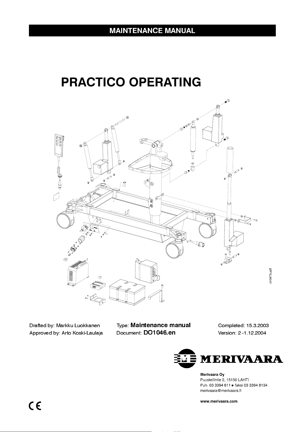
PRACTICO OPERATING TABLE
Drafted by: Ma rkk u Lu okk a ne n Type :
Maintenance manual
Approved by: Arto Koski-Laulaja Document:
DO1046.en
Completed: 15.3.2003
Version: 2 -1.12.2004
f
d
p
.
b
7
4
0
1
o
1 WARNINGS AND OBSERVATIONS
5
2 GENERAL
2.1 Opening packa ging 8
2.2 Removing opera ting tab le from pal let 8
3 TECHNICAL SPECIFICATIONS
3.1 Type plate 9
3.1.1 Figure symbols 9
3.1.2 Surface ma teria ls 9
3.2 Properties 10
3.2.1 Environmental conditions 10
3.2.2 Electrical pro perties 10
3.2.3 Rating specifications 10
3.2.4 Settings 11
3.2.5 Weights and dimensions 11
3.3 Structure 12
7
9
3.3.1 Main com pone nts 12
4 MAINTENANCE AND REPAIR
4.1 Maintenance procedures 13
4.1.1 Daily ma intena nce 13
4.1.2 Monthly ma intena nce 13
4.1.3 Annual maintenance 13
4.2 Troublesho oting a nd checkl is t 14
4.3 Removal of ca s ings 15
4.3.1 Table base casing 15
4.3.2 When table bas e cas ing heigh t is suffici ent 15
4.3.3 When table base casing is to be raised and turned 15
4.3.4 Removal of upper bellows end 15
4.3.5 Removal of column casings 16
4.3.6 Height adjustment motor stuck in lowest position 16
13
2
4.4 Replacement of tabl e bas e com ponen ts 17
4.4.1 Battery pack 17
4.4.2 Control unit 17
4.4.3 Power so urce 18
4.4.4 Charging/charge status controller 18
4.4.5 Fuses 19
4.4.5.1 Di strib ution fus es 19
4.4.5.2 Ba ttery fus e 19
4.4.5.3 P ow er so urce fus es 19
4.5 Replacement of moto rs 20
4.5.1 Removal/mounting of height adjustment motor 20
4.5.2 Removal /mounting of ba ck s ection a djus tment mo tor 20
4.5.3 Removal of Trendelenburg motor 21
4.5.4 Mounting of Trend elenburg moto r 21
4.5.5 Removal of side tilt motor 22
4.5.6 Mounting of s ide tilt moto r 22
4.5.7 Removal /mounting of ma ttress ba se lo ngitudi nal adj us tment moto r 22
4.6 Replacement of ga s s prings 23
4.6.1 Removal of Trendelenburg gas spring 23
4.6.2 Mounting of Trend elenburg gas spr ing 23
4.6.3 Removal of side tilt gas spring 23
4.6.4 Mounting of s ide tilt gas sp ring 23
4.6.5 Replacement of hea d sec tion ga s spring 24
4.6.6 Removal of ga s sp ring fro m pro tective tubing 24
4.6.7 Removal of back section gas spring 24
4.6.8 Replacement of leg sectio n gas spr ing 25
4.7 Replacement of cas to rs 26
4.7.1 Casto r ad jus tment 26
4.8 Adjustment of column wed ges 27
4.9 Removal/mo unting of ba ck sectio n 26
4.10Schematics 27
3
5 CLEANING 29
5.1Daily cleaning and disinfecting 29
5.1.1 Disinfecting: 29
5.1.2 Drying 29
6 RECYCLING 29
6.1Metals and plastics 29
6.1.1 Gas sp rin g s 29
4
1. WARNINGS AND OBSERVATIONS
!
In order to ensu re op tima l su rg ical sa fety, all operatin g tab le us e rs sh ou ld
carefully read the operating table and maintenance instructions before using the table.
The ent ire surgi c al wa r d s t af f s ho uld be fami l ia r w ith the c o r r ec t use of t he P RA CTICO Operati ng table as w ell
as all warnings and observations concerning it.
Warnings and observations found in this instruction manual are indicated as follows:
!
!
!
!
!
!
WARNING!
NOTE! Please observe in order to avoid causing damage to the equipment or its parts.
When se tting the op era tin g tab le into di ffere n t posi tion s, e ns ure tha t the pa tie nt’s fing e rs , ha nd s or other
parts of the body are not caught between moving parts on the back/leg section or seat.
Always follow manufacturer instructions when using diatherm or defibrillation equipment.
Combustible anaesthetic gases must not be used with the table.
Before ma ki ng an y ad ju s tme n t of the ope ratin g tab le , ens u re tha t the pa tie nt will not fall .
Please observe to ensure patient safety.
!
!
!
!
Lock the castors b efore us in g the op era ting tab le .
Set the operating table surface as low as possible while transporting to ensure transport comfort. Transport
the operating table with the leg section at the front. Remember the directional castor!
Note! If the operating table surface is not raised high enough when the leg section is dropped into its lowest
position, it may impact with the table base casing damaging the operating table and creating pinching
hazard.
Note! If the operating table surface is not raised high enough when trendelenburg and side tilt are in their
extreme positions, back section may impact the table base casing damaging the operating table and
creating pinching hazard.
5
!
WARNINGS AND OBSERVATIONS
!
When using the table, ensure that all accessories are properly mounted to it and check the function of acces-
sory lockings and adjustments.
When using the speciality headrest (100020126), ensure patient safety by releasing the headrest locking
!
!
!
!
!
!
!
before adjusting the back section. A warning label is affixed to the headrest.
The antistatic properties of the operating table require the use of Merivaara brand mattresses and antistatic
flooring.
Gas spring dismantling instructions are available from your sales representative. The release of nitrogen gas
is strictly
If the operating table has been in the cold, it must be allowed to warm up at room temperature for at least 6
hours before recharging the battery or switching on, to allow any condensation formed to evaporate.
All packa g in g cardb oa rd sh ou ld be recycle d . Wood an d pla s tics are en erg y was te .
The op era ting tab le is he a vy (165 kg).
We recommend recharging the battery regularly overnight after a day’s use. This ensures that the table is
always ready for use and it extends the battery life. Charging takes approx. 5-10 hours, depending on the
battery charg e sta tus . Th e ba tterie s al so have su fficie n t capa city to be charg e d only on ce a we e k.
prohibited, without followi n g the proper instructions.
!
!
!
!
!
!
The eq u ip ote ntia l po int (DIN 42801) is located on the tab le ba se .
We recommend use of the equipotential point whenever operating and when using
patient monitoring equipment. Read all manufacturer instructions.
Dry the operating table carefully
If the operating table batteries should quit during a procedure, connect the table to the main power supply
and continue as normal. Batteries can be charged while adjusting the table.
The switch in the table base can also be used as an emergency shutoff, if necessary.
Because batteries are problem waste, they must taken to a problem waste disposal facility.
When moving the operating table, ensure that any acces sories mounted on the side or the back section
kidney elevator crank do not cause any damage.
by wiping down with a dry cloth immediately after cleaning or disinfecting.
6
2. GENERAL
Dear operating table owner, The safe and fault-free use and maintenance of the equipment requires careful
adherence to these instructions. When mounting accessories to the equipment, the instructions provided
with them must be followed closely. Always keep the instructions for accessories together with this manual.
The Practico Op era ting Tab le me e ts the following sta nd a rds : IEC 601-2-46, IEC 601-1-2 (EMC) and SFS-EN
I
60601-1. The table complies with directive 93/42/EEC (MDD) product class
on this classification.
Intended use
The Merivaara Practico Operating Table is intended for general surgical use. It is also well suited for
outpatient surgical applications. The Practico works on both battery and mains power. The Practico can be
moved from one place to another. easily.
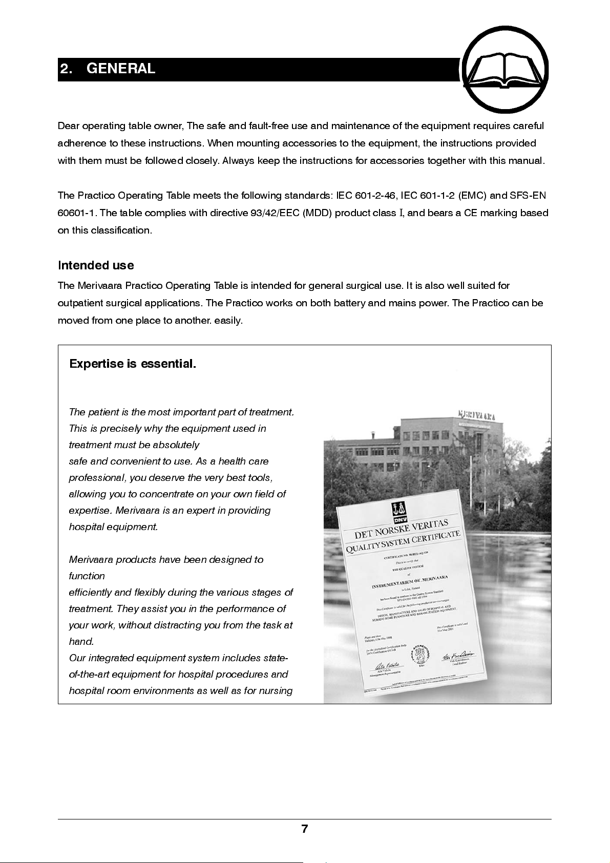
Expertise is essential.
, and bear s a CE ma r ki ng ba sed
The patient is the most important part of treatment.
This is precisely why the equipm ent used in
treatment must be absolute ly
safe and convenient to use. As a health care
professional, you deserve the very best tools,
allowing you to concentrate on your own field of
expertise. Merivaara is an expert in providing
hospital equipment.
Merivaara prod ucts have bee n desi gned to
function
efficiently and flex ib l y duri ng the vari ous stag es of
treatment. They assist you in the performance of
your work, without distracting you from the task at
hand.
Our integrated equipment system includes state-
of-the-art equipment for hospital procedures and
hospital room envi ronm ents as wel l as for nurs ing
7
2.1 Removing packaging
The operating table is preassembled in its packaging. Inspect the operating table for any shipping damage.
!
!
NOTE!
NOTE!
If the operating table has been in the cold, allow it to warm up at room temperature for at least
6 hours before recharging the battery or switching on, to allow any condensation formed
to evaporate .
All pack ag in g cardb oa rd sh ou ld be recycle d . Wood and pl as tics are ene rgy wa ste .
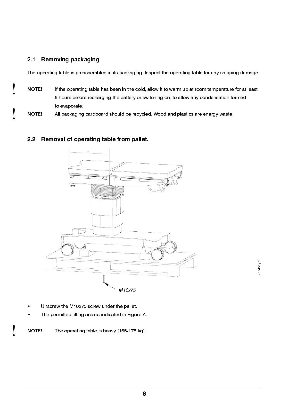
2.2 Removal of operating table from pallet.
!
M10x75
• Unscrew the M10x75 screw under the pallet.
• The permitted lifting area is indicated in Figure A.
NOTE!
The op e ratin g tab le is h ea vy (165/175 kg).
8
f
d
p
.
b
5
4
0
1
o
3. TECHNICAL SPECIFICATIONS
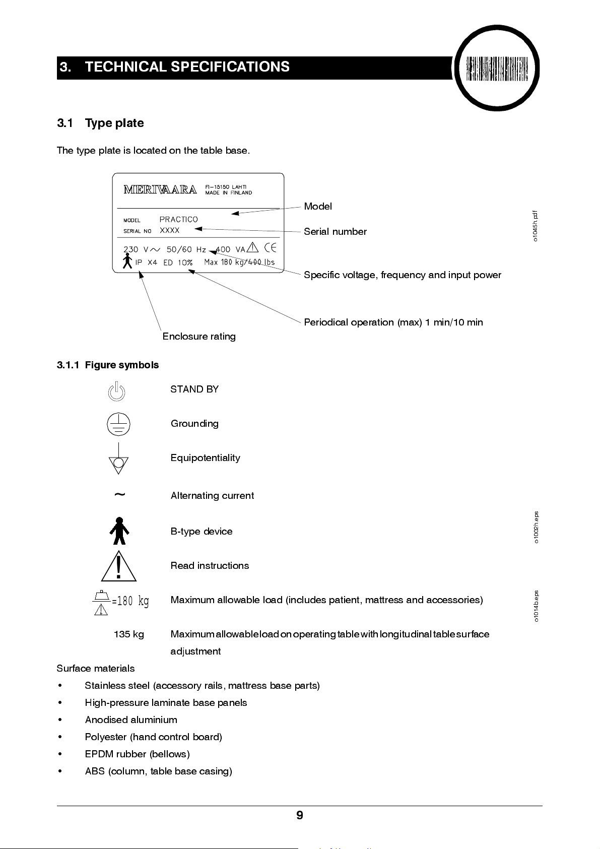
3.1 Type plate
The type plate is located on the table base.
3.1.1 Figure symbols
~
Enclosure rating
STAND BY
Grounding
Equipotentiality
Alterna tin g curre n t
B-type de vice
Model
Serial number
Specific voltage, frequency and input power
Periodical operation (max) 1 min/10 min
f
d
p
.
h
5
4
0
1
o
s
p
e
.
h
2
0
0
1
o
!
Read in struction s
=180 kg
135 kg Maximum allowable load on operating table with longitudinal table surface
Surface materials
• Stainless steel (accessory rails, mattress base parts)
• High-pressure laminate base panels
• Anodised aluminium
• Polyester (hand control board)
• EPDM rubber (bellows)
• ABS (column, table base casing)
Maximum allowable load (includes patient, mattress and accessories)
adjustment
9
s
p
e
.
b
4
1
0
1
o
3.2 Properties
3.2.1 Environmental conditions
Ambie n t temp e rature +10- +40 °C
Ambie n t air pres s ure 700- 1060 mbar
Relative hu m id ity 30 %- 75 %
Transport tempera ture -10- +40 °C
Storage temperature +10- +40 °C
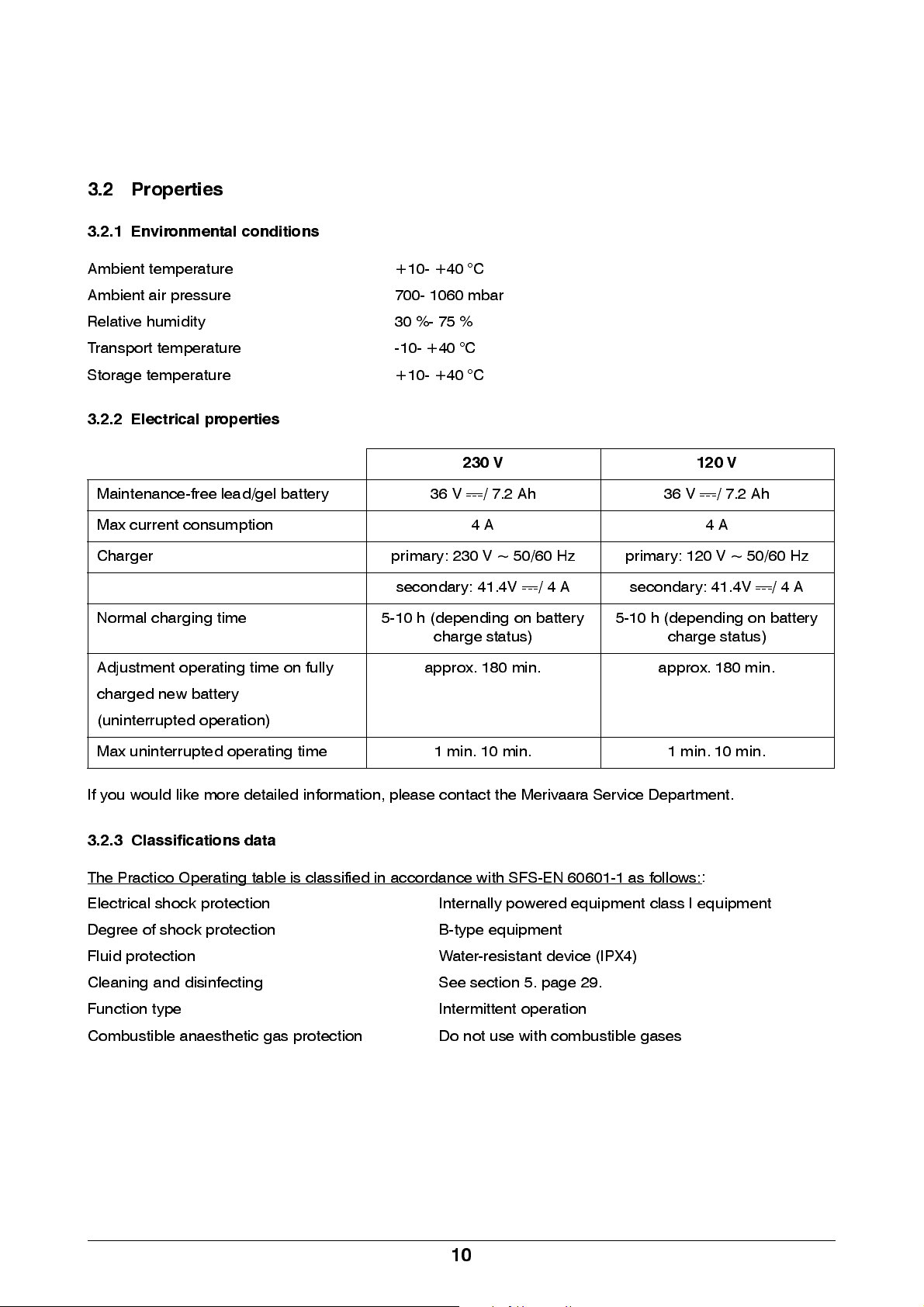
3.2.2 Electrical properties
230 V 120 V
Maintenance-free lead/gel battery 36 V / 7.2 Ah 36 V / 7.2 Ah
Max current consumption 4 A 4 A
Charger primary: 230 V ~ 50/60 Hz primary: 120 V ~ 50/60 Hz
secondary: 41.4V / 4 A secondary: 41.4V / 4 A
Normal charging time 5-10 h (depending on battery
charge status)
Adjustment operating time on fully
charge d ne w b attery
(uninte rrup ted ope ra tion)
Max uninterrupted operating time 1 min. 10 min. 1 min. 10 min.
If you would like more detailed information, please contact the Merivaara Service Department.
3.2.3 Classifications data
The Practico Op era ting tab le is clas s ifie d in accord ance with SF S -E N 60601-1 as follows :
Electrical shock protection Internally powered equipment class I equipment
Degre e of sh ock prote ction B-type equip m e nt
Fluid protection Water-resistant device (IPX4)
Cleaning and disinfecting See section 5. page 29.
Function type Intermittent op era tion
Combustible anaesthetic gas protection Do not use with combustible gases
approx. 180 min. approx. 180 min.
5-10 h (depen di ng on b attery
charge status)
:
10

3.2.4 Adjustments
Heigh t adj us tme nt 730-1030mm
Height adjustment, l ongitudinaldisplacement of table top 80-1080mm
Longitu di na l di sp la ce men t of table top 300mm
Side tilt
±
20°
Back section 100020120/100020130 -4° - +70°
Back section 100020131/100020135 -30° - +70°
Back section 100020122 -30° - +70°
Back section 100020125 -15° - +70°
Leg section -90° - +25°
Trendelenburg and anti-Trendelenburg 26°
Headre st (sta nd a rd) - 45°- +30°
3.2.5 Weights and dimensions
STANDARD LONGITUDINAL
ADJUSTMENT
Operating table surface 4-part 4-part
Operating table weig ht 165 kg 175 kg
Length (A) 2040 mm 2040 mm
Width (B) 535 mm 535 mm
Heigh t (C) 730-1030 mm 780-1080 mm
Table base leng th (D) 1080 mm 1080 mm
Mattress wid th (E) 540 mm 540 mm
Mattress base width (F) 594 mm 594 mm
Base panel height (G) 40 mm 40 mm
Castors 125 mm 125 mm
Longitu di na l ad j ustme n t of mattres s ba s e 300mm
Taulukko 1. Dimensions
Split leg section H= 535mm
One-piece leg section H=505mm
f
d
p
.
i
5
4
0
1
o
11

3.3 Structure
3.3.1 Main components
Head section
Back section
Seat section
Leg section
Hand control
Charging/ char ge status
controller
Trendelenburg gas spr ing
Side tilt gas spring
Trendelenburg motor
Power sour ce
Batteries
Charging outlet 230/120V
Switch
Distribution fuses
f
d
p
.
d
5
4
0
1
o
Control unit
Side til t motor
Height adjustment
motor
Directional castor
f
d
p
.
t
6
4
0
1
o
Equipotenti al poi nt
12

4. MAINTENANCE AND R EPAIR
4.1 Maintenance procedures
We recommend the following advance check-up and maintenance procedures to ensure continued
maintenance and trouble-free operation.
4.1.1 Daily maintenance
• During normal cleaning of the table, make a general visual inspection to ensure that it is in proper
working order.
• The PRACTICO Operating Table must be cleaned after each surgical procedure.
• We recommend that the batteries be charged every day. This will ensure a sufficient battery charge
and long service life
!
!
4.1.2 Monthly maintenance
• Lubricate all tabl e jo ints with lig h t mach in e oil .
• Ensu re tha t all cas tors roll eas il y and lock secu re ly.
• Check all table functions by fully extending and retracting them.
• Ensure that motor-equipped back sections are properly mounted to the seat. If necessary, tighten the
locking screws. See section 4.9 page 26.
• Ensure that the accessory rails are properly mounted.
4.1.3 Annual maintenance
• Perform all the same inspections as in monthly maintenance.
• Check and adjust column clearance, if required.
• Check cables and their connections.
All electrical repairs must be performed by a licensed electrician.
Before pe rform in g ma in te na n ce proce d ure s :
• Disconnect power supply
f
d
p
.
b
6
4
0
1
o
• Turn switch to STAND BY position
• Support the table part being repaired before removing the motor or gas spring.
13

4.2 Troubleshooting and checklist
When troubleshooting, check the following items first:
• Does the malfunction affect all table functions?
• Does the malfunction only affect one control function?
• If the problem on ly affe cts one control fu nction , d oes it do so in b oth di rection s ?
• Is the malfu n ction tha t the tabl e doe s n ot move or that it will not main tai n its po si tion?
The following components are common to all systems. If there is a malfunction in these, all control functions
will be affe cted .
• Control unit
• Hand control unit
• Battery
• Power source/battery
If there is a malfunction in one of the following components, it usually affects only one function.
• Motor
• Gas spring
Malfunction Cause
Table adjustments do not function. • Switch is in STAND BY position
• Hand control is unplugged
• Battery is dead
• Fuse is blown
• Faulty hand control
• Faulty control unit
Table functions are sluggish and weak. • Low battery charge
•Faulty motor
Operating table function duration is short, even
though the battery has been charged in accordance
with instructions.
Castors ma k e ab n orm al nois e s wh en rolling • Pedal in wron g po si tion
• Faulty charger
• Faulty battery
• Battery too old
• Castor bearings worn
• Incorrect castor adju stm e nt
14

4.3 Removal of casings
4.3.1 Table base casing
1 2
4
3
o1046b.pdf
o1046v.pdf
4.3.2 When table base casing height is sufficient
• Disconnect power supply
• Remove casing screws (3) 2 pcs.
• Raise the casing (2) from its seat and hang from the mattress base or separate from the table base
with suitable spacers .
• Remove cover (4) by lifting it upwards.
4.3.3 When table base casing is to be raised and turned
• Disconnect power supply
• First, remove the four screws (1)
• Raise the telescoping column casi ngs and hang from the mattress base.
• Disconnect the hand control connector from the table base.
• Remove casing screws (3) 2 pcs. Raise the casing from its seat, turn into the desired position and
hang from the mattress base or separate from the table base with suitable spacers. Remove cover (4)
by lifting it upwards.
• Reassemble in reverse order.
4.3.4 Removal of upper bellows end
3 3
• Remove the four screws (3), which fasten the
bellows to the seat.
f
d
p
.
c
6
4
0
1
o
15

4.3.5 Removal of column casings
• Remove the 13 screw caps (1) and screws (2), which fasten
the bellows and casing to the column.
4.3.6 Height adjustment motor stuck in lowest position
2
1
!
!
WARNING!
• Push the top of the bellows down and remove the lock ring (1)
• Remove the pin (2) and raise the seat.
WARNING!
Before removing the pin on top of the heigh t adjustment motor (3), ensure that the seat
will not fall.
The seat must not be raised more than 250 mm.
Support the seat so that it will not fall.
1
3
2
• Remove the table base casing (see section 4.3.1 page 15)
• Reassemble in reverse order.
16

4.4 Replacement of table base components
4.4.1 Battery pack
• Disconnect power supply
• Turn switch to STAND BY position
• Raise and turn the table base casing (see section 4.3.3 page 15)
• Disconnect the battery pack connector.
• Remove the mounting bar by unscrewing (1)
• Lift o ut th e batte r y p ack .
.
1
Mounting bar
Battery pack
4.4.2 Control unit
• Disconnect power supply
• Turn switch to STAND BY position
• Raise and turn the table base casing (see section 4.3.3 page 15)
• Disconnect the control unit by pulling it up.
• Disconn e ct all conn e ctors. Re m e mb e r the p ositions of ea ch conn e ctor!
Control unit
f
d
p
.
g
6
4
0
1
o
f
d
p
.
g
6
4
0
1
o
17

4.4.3 Power source
• Disconnect power supply
• Turn switch to STAND BY position
• Raise and turn the table base casing (see section 4.3.3 page 15)
• Disconnect the battery pack connector.
• Disconnect the power source connection.
• Unscrew the mounting screws a few turns.
• Move the power source slightly to the side and lift out.
.
Mounting screws
Move in the direction
of the arrow.
Power source
Mounting screws
4.4.4 Charging/charge status controller
• Disconnect power supply
• Turn switch to STAND BY position
• Raise and turn the table base casing (see section 4.3.3 page 15)
• Disconnect the battery pack connector.
• Disconnect power source (see section 4.4.3 page 18)
• Disconn e ct chargi ng / cha rge sta tus controller conn e ctors
• Unscrew the mounting screws a few turns.
• Lift out the charging/charge status controller.
f
d
p
.
g
6
4
0
1
o
Screw
18
Charging controller
f
d
p
.
h
6
4
0
1
o

4.4.5 Fuses
4.4.5.1 Mains fuses
• Position (see section 3.3.1 page 12)
• Open the fuse box and replace fuses.
Fus e s T 6 . 3A
4.4.5.2 Battery fuse
• Open battery casing cover
• Replace fuse
• Carfuse 15A Size: 5.3 x 19.1 x 18.7 mm.
f
d
p
.
f
6
4
0
1
o
4.4.5.3 Power source fuses
• Located inside the power source.
• Fuse T6.3A (2 pcs.)
19

4.5 Replacement of motors
!
!
WARNING!
WARNING!
Before opening the table base casing, disconnect the power supply.
Before removing gas springs, ensure that the piston rod is locked or the spring is
unloaded.
4.5.1 Removal/mounting of height adjustment motor
• Loosen ta bl e bas e c as in g sc rews (see secti o n 4 . 3 . 3 page
15).
• Remove upper bellows end (see section 4.3.4 page 15).
• Remove colu m n cas in g s (see se ction 4.3.5 page 16).
• Remove support plate (3).
• Remove top of motor (see section 4.3.6 page 16).
• Remove the lock ring (1) from the bottom of the motor and
remove the joint pin (2).
• Disconnect the motor from the control unit.
• Transfer the support tubing (4) to the new motor.
4
3
4.5.2 Removal/mounting of back s ection adjustment motor
• Disconnect the motor from the control unit (3).
• Remove lock rings (1)
• Hold the ba ck se ction in pl ace an d rem ove joi nt
pins (2).
o1046x.pdf
3
f
1
d
p
2
.
i
6
4
0
1
o
2
1
f
d
p
.
p
6
4
0
1
o
1
2
20

4.5.3 Removal of Trendelenburg motor
• Remove column casings and bellows (see section
4.3.4 page 15) and (see section 4.3.5 page 16).
1
• Limiter bushing (1) code A41538100.
• Mount the limiter bushings (1) around the gas spring
piston rod. Run the motor carefully, so that the limiter
bushings stay in place and there is a gap between the
5
5
moto r mo unt ing pi ns. Th e limi ter bush ing lo ck s out the gas
spring when the motor is turned off.
• Remove the lower lock ring (2) and joint pin (3).
• Remove the upper hex nut (4).
• Disconnect the motor from the control unit.
• Remove the gas spring (5) loosen the joint screws (6) only until th e motor com es free. Hold the other
gas spring in place to prevent the mattress base from turning.
If you remove both gas springs,
support the base to prevent it from falling.
4.5.4 Mounting of Trendelenburg motor
• Ensu re tha t the cab le is fixe d to the mo tor with a
f
d
p
.
j
6
4
0
1
o
cable tie..
• Mount the top of the motor and gas springs.
• Conne ct the mo tor to the control uni t.
• Run the motor until the joint pin on its bottom falls into
place (3).
• Fasten lock ring (2).
• Run the motor until you can remove the limiter
bushings from the gas spring.
6
4
5
f
d
1
3
p
.
k
6
4
0
1
o
2
21

4.5.5 Removal of side tilt motor
!
WARNING!
Before removing the motor, ensure that the gas spring piston rod is locked.
The gas spring is traction type.
• To lock out the gas spring, loosen the nut (1) on the end 2.5
turns. Carefully test with the side tilt motor that the gas
spring is securely locked out.
• Run the motor carefully until there is a gap between mounts.
• Disconnect the motor from the control unit.
• Unscrew the motor mounting screws (2) and remove the
motor.
4.5.6 Mounting of side tilt motor
• Ensu re tha t the le ad is con ne cted to the motor with a cab le
tie.
• Mount one end of the motor and connect it to the control
unit.
• Run the motor until the screw on the other end is in place.
• Tighten the gas spring nut (1).
2
f
d
p
.
l
6
4
0
1
1
o
2
• Ensure that the gas spring moves freely.
4.5.7 Removal/mounting of mattress base longitudinal adjustment motor
• Remove the upper part of the bellows and table base casing (see section 4.3.2 page 15) and (see
section 4.3.4 pag e 15).
• Loosen the mattress base screws (1) and
remove base panel (2).
• Loosen the casi ng sc rew s (3 ) and r emov e ca sing
4
3
2
(4).
• Mark the gearwheel and bar positions for
reassembly.
• Loosen screw s (5) and lift pa rt (6) out.
• Loosen the motor (10) mounting screw (7),
10
5
6
9
8
disconnect the motor from the control unit, and
lift the motor with all pa rts ou t.
• Loosen screws (8) and remove parts (9).
7
• Replace motor and reassemble in reverse order.
1
f
d
p
.
o
6
4
0
1
o
• Ensure that the gearwheels and bar positions are the same.
22

4.6 Replacement of gas springs
4.6.1 Removal of Trendelenburg gas spring
• Remove column casings and bellow (see section 4.3.4 page 15)
and (see section 4.3.5 page 16).
• Mount the limiter bushings (see section 4.5.3 page 21) around the
6
4
gas sp rin g p is ton rod. Run the motor carefu ll y, so that the limiter
5
bushings stay in place and there is a gap between the motor
mounting pins. The limiter bushing locks out the gas spring when
the motor is turne d off. Th e g as sp ring is traction type .
1
• Support the mattress base to prevent it from falling when the gas
springs are removed.
• Remove the upper hex nut (4) and joint screw (6).
• Remove the lower gas spring locking rings and the motor bottom.
• In order to remove the le ft gas spri ng , the lowe r pa rt of the latera l
tilt motor must first be rem ove d . Se e se ction 4.5.5 pag e 22.
4.6.2 Mounting of Trendelenburg gas spring.
• Fasten the gas springs and motor to the top end (joint screw (6) and h ex nut (4)).
• Remove the mattress base support and angle until the lower ends of the gas springs can be fastened.
• Run the motor to its minimum extension and angle the mattress base until the bottom of the motor can
be fastened.
4.6.3 Removal of side tilt gas spring
f
d
p
.
k
6
4
0
1
o
!
WARNING!
Before removing the gas spring, ensure that the gas s pring piston rod is locked.
• To lock out the gas spring, loosen the nut (1) o n the end 2.5 turns.
Carefully test with the side tilt motor that the gas spring is securely
locked out.
• Run the motor carefully until there is a gap between mounts.
• Loosen the ga s spr i ng moun t i ng sc r e ws ( 2 ) and remove gas spr i ng .
2
4.6.4 Mounting of side tilt gas springs
• Transfer the bushing (4) to the new gas spring. Turn the bushing
3
until the screw (2) fits into the bushing hole.
• Carefully s c r ew t he bush in g i nt o pl ac e. Wh en t he gas spri ng pi st o n
rod begins to move, adjust to the same length as on the old gas
1
2
4
spring. Be careful not to allow too much play in the gas spring.
• Mount the gas spring into place, using the motor to assist.
• Tighte n the nu t (1) on the end of the ga s sp ring an d ens u re tha t the sp rin g m ove s free ly.
23
f
d
p
.
l
6
4
0
1
o

4.6.5 Replacement of head section gas spring
• Raise the head section into its upper position.
• Remove locking ring (1)
• Remove pin (2).
• Loosen the nut (3).
• Unscrew the gas spring (4). Count the
number of turns for reassembly.
4.6.6 Removal of gas spring from protective tubing
• Remove the ga s sp rin g ram (1).
• Pull the gas spring (2) out of the protective tubing (3).
• Unscrew the mount (4). Count the number of turns
for reassembly.
• If the gas spring requires adjustment:
• first turn the mounting bracket (4) to its old position
1
24
f
d
p
.
n
3
3
2
6
4
0
1
o
s
p
e
.
g
9
0
0
1
o
4
1
• adjust only by half a turn or one whole turn at a time
• if the gas spring is still under load, turn counterclockwise
• if lifting the handle does not release the gas spring, turn clockwise
4.6.7 Replacement of back section gas sp ring
• Replace gas s pr i ngs on e at a tim e, s o t ha t o ne i s lef t to
supp ort the ba ck se ction .
• Raise the back section into its upper position.
• Remove screws (1) and bushings (2).
• Turn the acces s ory rail (3) to the side .
• Remove the locking ring (4).
• Remove the retaining screws (7).
• Remove pins (5).
• Remove gas spring (6).
• Removal of gas spring from protective tubing (see
section 4.6.6 pag e 24)
f
d
p
.
n
6
4
0
1
o
2
1
5
6
34
1
5
2
24
7

4.6.8 Replacement of leg section gas spring
Remove the leg section from the operating table and
turn upside down.
• Remove scre ws (1).
• Remove bushings (2).
• Turn the acces s ory rail (3) to the side .
• Remove locking rings (4)
• Remove pins (5).
• Removal of gas spring from protective tubing
(see section 4.6.6 page 24)
4.7 Replacement of castors
• Raise the table base cas ing (see section
4.3.2 page 15)
• Put the brake pedal (1) into its free position.
• Loosen screws (3).
• Loosen screws (4).
• Move the brake bar to the side. (2).
4
6
4
5
3
2
1
5
f
d
p
.
u
6
4
0
1
o
4
• Remove the castor.
• Reinstall castor in reverse order. Ensure that the
brake pedal and cam positions are in alignment
and that the castor is facing in the right direction.
4.7.1 Castor adjustment
•
Engage the brakes.
• Loosen screws (3).
• Move the brake bar to the side (2).
• Braking power is increased by turning the castor axle
counter-clockwise one rotation at a time (as seen from
above). Use a large screwdriver or similar tool.
21 33 4
2
f
d
p
.
r
6
4
0
1
o
f
d
p
.
s
6
4
0
1
o
25

4.8 Adjustment of column wedges
• Remove colu m n cas in g s (see se ction 4.3.1 page 15).
• Loosen the two retaining screws (1) on either side of the column.
• Loosen the two lock ing nu ts (2), one on e ithe r sid e of the colu mn .
• Adjust the column so that it moves without exposing g aps
using the adjuster screws (3).
The adjuster screw torque is 3-4 Nm.
• Move the column up and down and check for gaps.
• Lock the adjuster screws (3) with locking nuts (2) and ensure that
the adj us ter scre ws rem ain in p la ce wh ile tigh ten in g .
• Tighten the retaining screws (1).
4.9 Removal/mounting of back section
• Remove motor connector (6) (see section 4.5.2 page 20)
• Remove motor (see section 4.5.2 page 20)
• Loosen screws(1) two turns.
• Remove ba ck se ction by pu ll in g it horizonta lly
out from middle section.
• Loosen frame connector(6) mounting nut(7)
and remove connector.
• Loosen middle section table top screws(2)
• and remove table top(3).
• If necessary, remove motor mounting plate(4)
by loosening screws(5)
2
1
2
3
s
p
e
.
h
6
2
0
1
o
1
2
• Re-as se m b le in reve rs e ord er.
NOTE! Tighten screws (1) to 40 Nm.
• If you replace the ba ck se ction with a di ffere n t mod el ,
ensure that the motor is facing the right way.
7
6
26
3
45 5

4.10 Schematics
16 17 18 19
15
14
13
1234
12
8
10 11
9
77
1
2
3 5
4
20
6
f
d
p
.
c
7
4
0
1
21
o
27

Number of parts in assembly
Item Code Part name Additional informati on
1 7134254 Fuse 15A 1
2 71336015 Piezo buzzer 1
3 71336017 LED Green 1
4 71336016 LED Yellow 1
5 7134259 Device header 1
6 A41527600 Wire bundle Power source – device header 1
7 A31529100 Wire bundle Buzzer - LEDs 1
8 A41527700 Wire bundle Battery pack – ESU 7320 1
9 A21513500 Battery pack 36V 7.2 Ah 1
10 71335972 Circuit breaker 1
11 A41527800 Wire bundle Main switch – power source 1
12 A41527900 Wire bundle Control unit – main switch 1
13 71336074 Control unit 1
14 71335468 T-wire 1
15 71335469
71335470
71335471
16 71335475
71335476
17 71335447 Actuator Side tilt 1
18 71335442 Actuator Height 1
19 71335446 Actuator Trendelenburg 1
20 7133561 Power source ADC 4380 + ESU 7320 1
21 7134275 Fuse T 6.3A 2
Hand control
Hand control
Hand control
Actuator
Actuator
H/T/St (3-settings)
H/S/T/St (4-settings)
H/T/St/L (4-settings)
Back
Longitudinal adjustment
1
1
1
1
1
28

5.
CLEANING
5.1 Daily cleaning and disinfecting
The PRACTICO Operating Table should be cleaned after every surgical procedure, before beginning another
surgery. The mattresses and operating table surface are cleaned by wiping down with a lightly alkaline
detergent
(pH 7-8).
5.1.1 Disinfecting:
Wipe down with a 3% chloramine-based disinfectant (Klorilli) or similar cleaning agent.
Normal excretion stains from patients are cleaned and disinfected with a 10% chloramine-based disinfectant.
Excretion stains from isolation patients are cleaned and disinfected with a 25% chloramine-based
disinfectant.
5.1.2 Drying
!
NOTE!
disinfecting.
Dry the operating table carefully
by wiping down with a dry cloth immediately after cleaning or
29

6. RECYCLING
6.1 Metals and plastics
When disposing of an operating table or replacing any of its parts, check the recyclability of each item. A
majority of the metal used on the operating table is steel. The operating table also contains a number of zinc
and aluminium castings and brass bushings. When recycling plastic parts, determine the material type. The
surface materials list will provide assistance in determining the correct recycling procedure. If a part material
is missing from the table, contact your sa les representative. For more information on recycling, contact your
local waste management facility or visit related sites on the Internet.
Below are recycling symbols, which are marked on parts made of plastic. Products marked with these
symbols can be used as energy waste.
!
!
6.1. 1 Gas spring s
Gas springs can be disposed of as metal waste after all nitrogen gas and oil has been removed from them.
WARNING!
NOTE!
facility.
The release of nitrogen gas is strictly
Gas spring dismantling instructions are available from your sales representative.
Because batteries are problem waste, they must be taken to a problem waste disposal
prohibited, without following the proper instructions.
30

NOTES
v
a
a
r
a
-
i
r
e
M
31

 Loading...