

Meritor Differential Carriers Maintenance Manual
Single-Reduction
Differential Carriers
Maintenance Manual 5
Revised 10-06
Standard Carriers
Including: Single Axles,
Rear of Tandem Axles,
Front Drive Steering
Axles
Excluding RS and
RT Series (Rear Only),
Single-Reduction Axles
and RF Series Front
Drive Axles
Service Notes
Before You Begin
This manual provides instructions for Meritor’s
early production non-RF, -RS or -RT Series axles.
Before you begin procedures:
1. Read and understand all instructions an
procedures before you begin to service
components.
2. Read and observe all Caution and Warning
safety alerts that precede instructions or
procedures you will perform. These alerts help
to avoid damage to components, serious
personal injury, or both.
3. Follow your company’s maintenance and
service, installation, and diagnostics
guidelines.
4. Use special tools when required to help avoid
serious personal injury and damage to
components.
Safety Alerts, Torque Symbol
and Notes
A Warning alerts you to an
WARNING
CAUTION
T
NOTE
instruction or procedure
that you must follow
exactly to avoid serious
personal injury and
damage to components.
A Caution alerts you to an
instruction or procedure
that you must follow
exactly to avoid damage to
components and possible
serious injury.
A torque symbol alerts you
to tighten fasteners to a
specified torque value.
A Note provides
information or suggestions
that help you correctly
service a component.
Access Information on
ArvinMeritor’s Website
Additional maintenance and service information
for ArvinMeritor’s commercial vehicle systems
component lineup is also available at
www.arvinmeritor.com.
To access information, click on Products &
Services/Tech Library Icon/HVS Publications.
The screen will display an index of publications
by type.
Additional Information
For complete maintenance and service procedures
for all single-reduction differential carriers, call
ArvinMeritor’s Customer Service Center at
800-535-5560 to order the following publications.
앫 Traction Controls package contains two videos —
Splitting the Difference T-87127V and
Driver-Controlled Full Locking Main Differential
T-9007V. $50. Order T-95125V for this package or
each video is available individually as well.
앫 Technical Electronic Library on CD. Features
product and service information on most
ArvinMeritor, ZF Meritor and Meritor WABCO
components. $20. Order TP-9853.
How to Obtain Tools and Supplies
Specified in This Manual
Kiene Diesel Accessories, Inc., 325 S. Fairbanks
Street, Addison, IL 60101. Call the company’s
customer service center at 800-264-5950, or visit
their website at kienediesel.com.
SPX/OTC Service Solutions, 655 Eisenhower Drive,
Owatonna, MN 55060. Call the company’s service
center at 800-533-6128, or visit their website at
otctools.com.

Table of Contents
Exploded View . . . . . . . . . . . . . . . . . . . . . . . . . . . . . . . . . . . . . . . . . . . . . . . . . . . . . . . . . . . . . . . . . . . . . . . . . . 1
Section 1: Introduction
Standard Single-Reduction Carriers . . . . . . . . . . . . . . . . . . . . . . . . . . . . . . . . . . . . . . . . . . . . . . . . . . . . . . .4
Axle Models Covered in This Manual . . . . . . . . . . . . . . . . . . . . . . . . . . . . . . . . . . . . . . . . . . . . . . . . . . . . .5
Section 2: Disassembly
Axle Shaft Removal Methods . . . . . . . . . . . . . . . . . . . . . . . . . . . . . . . . . . . . . . . . . . . . . . . . . . . . . . . . . . . . 6
Brass Drift Method
Air Hammer Vibration Method
Remove Differential Carrier from Axle Housing . . . . . . . . . . . . . . . . . . . . . . . . . . . . . . . . . . . . . . . . . . . . .7
Carrier Removal from Axle . . . . . . . . . . . . . . . . . . . . . . . . . . . . . . . . . . . . . . . . . . . . . . . . . . . . . . . . . . . . . . 9
Remove the Differential and Ring Gear from the Carrier . . . . . . . . . . . . . . . . . . . . . . . . . . . . . . . . . . . . .11
Disassemble the Differential and Ring Gear Assembly . . . . . . . . . . . . . . . . . . . . . . . . . . . . . . . . . . . . . .13
Remove the Drive Pinion and Bearing Cage from Carrier . . . . . . . . . . . . . . . . . . . . . . . . . . . . . . . . . . . . 15
Disassemble the Drive Pinion and Bearing Cage . . . . . . . . . . . . . . . . . . . . . . . . . . . . . . . . . . . . . . . . . . .16
Section 3: Preparing the Parts for Assembly
Cleaning Ground and Polished Parts . . . . . . . . . . . . . . . . . . . . . . . . . . . . . . . . . . . . . . . . . . . . . . . . . . . . . 20
Cleaning Rough Parts
Cleaning Axle Assemblies
Drying Parts After Cleaning
Preventing Corrosion on Cleaned Parts . . . . . . . . . . . . . . . . . . . . . . . . . . . . . . . . . . . . . . . . . . . . . . . . . . .21
Inspecting Parts
Repair or Replacement of Parts, General . . . . . . . . . . . . . . . . . . . . . . . . . . . . . . . . . . . . . . . . . . . . . . . . . .23
Repair Axle by Welding . . . . . . . . . . . . . . . . . . . . . . . . . . . . . . . . . . . . . . . . . . . . . . . . . . . . . . . . . . . . . . . . 24
Bending or Straightening Drive Axle Housings . . . . . . . . . . . . . . . . . . . . . . . . . . . . . . . . . . . . . . . . . . . . 25
Removing Dri-Loc
Section 4: General Information
Installing Fasteners with Pre-Applied Adhesive, Meritor Liquid Adhesive 2297-C-7049,
Loctite
Installing New Fasteners with Pre-applied Adhesive Patches
Installing Original or Used Fasteners Using Meritor Liquid Adhesive 2297-C-7049 or
Loctite
Application of Meritor Adhesive 2297-T-4180 in Bearing Bores for the Differential
Application of Three Bond 1216 or Equivalent Silicone Gasket Material . . . . . . . . . . . . . . . . . . . . . . . .27
Installing Tight Fit Yokes and POSE™ Seal . . . . . . . . . . . . . . . . . . . . . . . . . . . . . . . . . . . . . . . . . . . . . . . .28
General Yoke and U-Joint Reassembly . . . . . . . . . . . . . . . . . . . . . . . . . . . . . . . . . . . . . . . . . . . . . . . . . . .29
Gear Set Information (Drive Pinion and Ring Gear Marks)
Section 5: Assembly
Assemble the Drive Pinion, Bearings and Bearing Cage . . . . . . . . . . . . . . . . . . . . . . . . . . . . . . . . . . . . .31
Adjusting Preload of Pinion Bearings . . . . . . . . . . . . . . . . . . . . . . . . . . . . . . . . . . . . . . . . . . . . . . . . . . . . . 36
Adjusting Shim Pack Thickness for the Pinion Cage (Depth of Pinion) . . . . . . . . . . . . . . . . . . . . . . . . . .41
Installing the Drive Pinion, Bearing Cage and Shim Pack into the Carrier . . . . . . . . . . . . . . . . . . . . . . . 43
Installing Tight Fit Yokes and POSE™ Seal . . . . . . . . . . . . . . . . . . . . . . . . . . . . . . . . . . . . . . . . . . . . . . . .44
Assemble the Main Differential and Ring Gear Assembly . . . . . . . . . . . . . . . . . . . . . . . . . . . . . . . . . . . .45
Inspecting the Rotating Resistance of the Differential Gears . . . . . . . . . . . . . . . . . . . . . . . . . . . . . . . . . .48
Install the Differential and Ring Gear Assembly . . . . . . . . . . . . . . . . . . . . . . . . . . . . . . . . . . . . . . . . . . . .49
Adjust Preload of Differential Bearings . . . . . . . . . . . . . . . . . . . . . . . . . . . . . . . . . . . . . . . . . . . . . . . . . . .50
Method 1
Method 2 . . . . . . . . . . . . . . . . . . . . . . . . . . . . . . . . . . . . . . . . . . . . . . . . . . . . . . . . . . . . . . . . . . . . . . . . . . . .52
Inspect Runout of Ring Gear . . . . . . . . . . . . . . . . . . . . . . . . . . . . . . . . . . . . . . . . . . . . . . . . . . . . . . . . . . . .53
Ring Gear Backlash Adjustment
Inspect Tooth Contact Patterns of the Gear Set . . . . . . . . . . . . . . . . . . . . . . . . . . . . . . . . . . . . . . . . . . . . 55
Install and Adjust the Thrust Screw . . . . . . . . . . . . . . . . . . . . . . . . . . . . . . . . . . . . . . . . . . . . . . . . . . . . . .60
Install Differential Carrier into Axle Housing . . . . . . . . . . . . . . . . . . . . . . . . . . . . . . . . . . . . . . . . . . . . . . .61
Straight Holes, Nuts and Hardened Washers . . . . . . . . . . . . . . . . . . . . . . . . . . . . . . . . . . . . . . . . . . . . . .63
Tapered Dowel, Hardened Washer and Hardened Nut
®
Fasteners
®
680 Liquid Adhesive or Equivalent . . . . . . . . . . . . . . . . . . . . . . . . . . . . . . . . . . . . . . . . . . . 26
®
680 or Equivalent

Table of Contents
Section 6: Lubrication . . . . . . . . . . . . . . . . . . . . . . . . . . . . . . . . . . . . . . . . . . . . . . . . . . . . . . . . . . . . . . . 64
Axle Lubricant Capacities . . . . . . . . . . . . . . . . . . . . . . . . . . . . . . . . . . . . . . . . . . . . . . . . . . . . . . . . . . . . . . 66
Section 7: Fastener Torque Information
Torque Values for Fasteners . . . . . . . . . . . . . . . . . . . . . . . . . . . . . . . . . . . . . . . . . . . . . . . . . . . . . . . . . . . 67
General Information
American Standard Fasteners
Metric Fasteners
Section 8: Adjustments and Specifications . . . . . . . . . . . . . . . . . . . . . . . . . . . . . . . . . . . . . . . . . . 71
Section 9: Vehicle Towing Instructions (Non-DCDL)
Before Towing or Drive-Away . . . . . . . . . . . . . . . . . . . . . . . . . . . . . . . . . . . . . . . . . . . . . . . . . . . . . . . . . . 73
After Towing or Drive-Away . . . . . . . . . . . . . . . . . . . . . . . . . . . . . . . . . . . . . . . . . . . . . . . . . . . . . . . . . . . 74
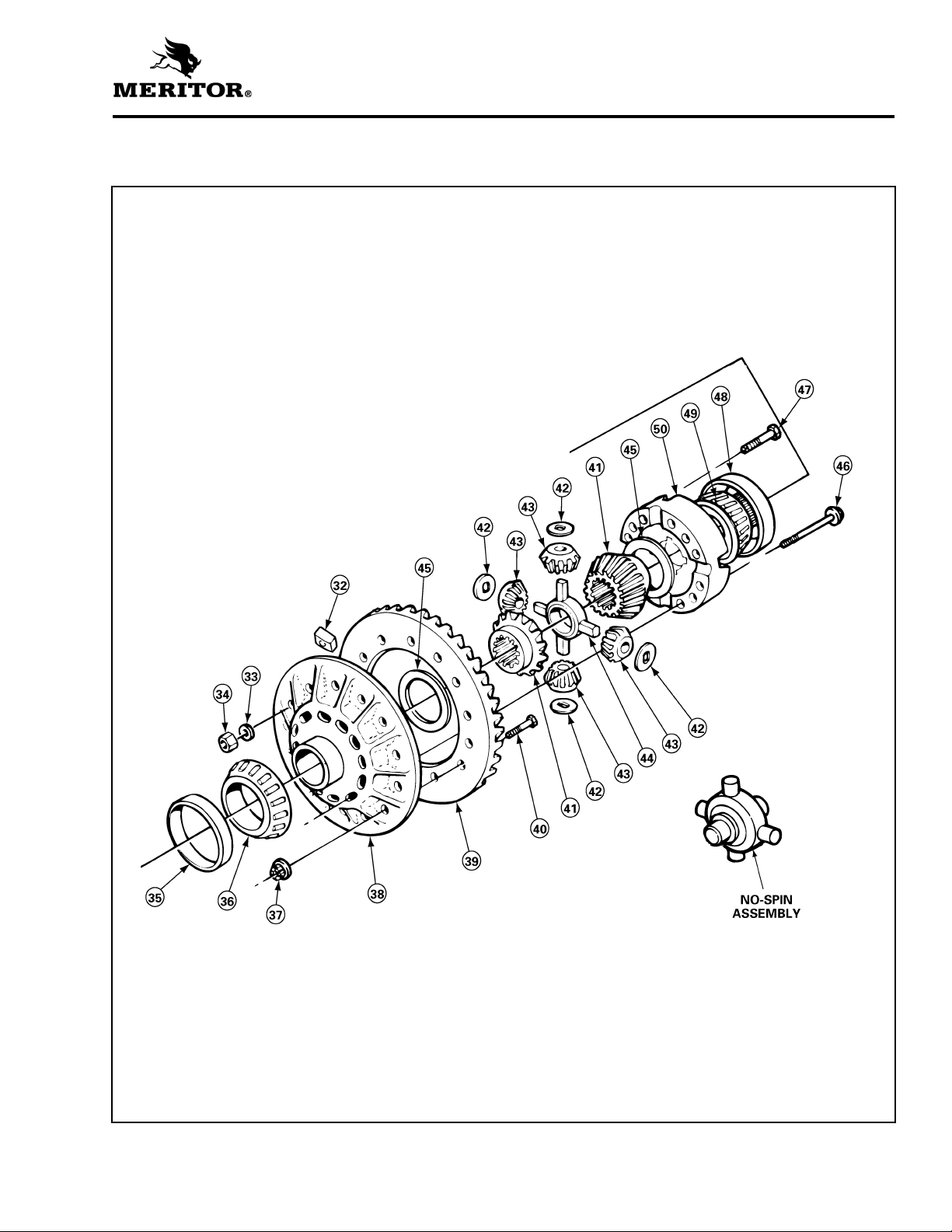
Exploded View — Legend
Exploded View
1 Nut — Drive Pinion
2 Washer — Drive Pinion*
3 Input Yoke* or Flange*
4 Deflector
5 Oil Seal
6 Capscrew — Bearing Cage
7 Washer
8 Bearing Cone — Pinion Outer
9 Bearing Cup — Pinion Outer
10 Bearing Cage — Drive Pinion
11 Shims
12 Spacer— Pinion Bearing
13 Bearing Cup — Pinion Inner
14 Bearing Cone — Pinion Inner
15 Drive Pinion
16 Spigot Bearing
16A Snap Ring
17 Carrier
18 Thrust Screw*
19 Jam Nut* — Thrust Screw*
20 Adjusting Ring — L.H.
26 Washers* — Lock Plate
27 Capscrews* — Lock Plate*
28 Adjusting Ring — R.H.
29 Plug* — Oil Fill Hole (carrier)
30 Washer* — Capscrew/Plug*
31 Capscrew/Plug — Sensor Hole
32 Thrust Block*
33 Washers* — Differential Case
34 Nuts* — Differential Case
35 Bearing Cup — Differential L.H.
36 Bearing Cone — Differential L.H.
37 Nuts* — Ring Gear and Case Half
38 Case Half — Flange
39 Ring Gear
40 Bolts* or Rivets* — Ring Gear and
Case Half
41 Side Gears —Differential
42 Thrust Washers — Differential Pinion
43 Pinions — Differential
44 Spider — Differential
45 Thrust Washers — Differential Side
Gear
21 Cotter* or Pin*
22 Caps — Differential Bearing
23 Washers
24 Capscrews — Differential Bearing Cap
25 Lock Plate* — Adjusting Ring
* Some Meritor carriers do not have these described parts.
NoSPIN® is a registered trademark of Tractech, a division of Dyneer Corp.
46 Capscrews — Differential Case
47 Bolts* — Differential Case
48 Bearing Cup — Differential R.H.
49 Bearing Cone — Differential R.H.
50 Case Half — Plain
1
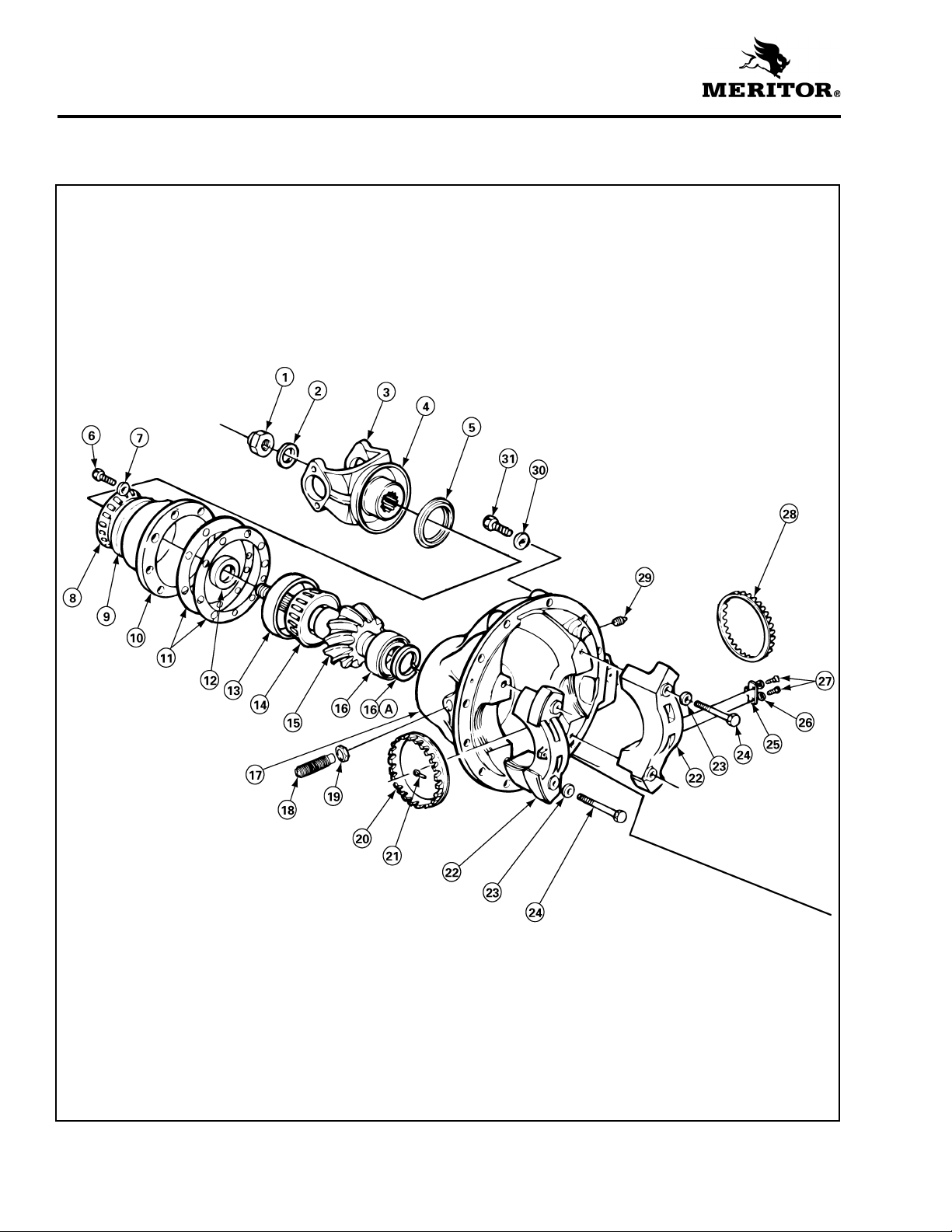
Exploded View
Single-Reduction Differential Carrier
2
Exploded View
3

Section 1
Introduction
Section 1Introduction
Standard Single-Reduction
Carriers
NOTE: For carriers with a differential lock, refer
to Maintenance Manual 5A.
Meritor single-reduction standard carriers,
Figure 1.1, are used in most Meritor single axles,
rear of tandem axles and front drive steering axles.
Figure 1.1
The single-reduction carrier models are front
mounted into the axle housing. These carriers
have a hypoid drive pinion and ring gear set and
bevel gears in the differential assembly.
A straight roller bearing (spigot) is mounted on the
head of the drive pinion. All other bearings in the
carrier are tapered roller bearings.
When the carrier operates, there is normal
differential action between the wheels all the time.
1 TAPERED ROLLER BEARINGS
2 CARRIER
3 STRAIGHT ROLLER BEARING
4 TAPERED ROLLER BEARING
4
5 BEVEL DIFFERENTIAL GEARS
6 HOUSING
7 TAPERED ROLLER BEARING
8 HYPOID DRIVE PINION AND RING GEAR
Axle Models Covered in This Manual
The following table lists all axle models covered in
this manual.
Single Drive Axles:
A-150 E-100 F-140 H-172 Q-100 R-163
B-100 E-105 G-161 L-100 Q-145 R-170
B-140 E-150 H-100 L-140 RL-170 S-170
B-150 F-100 H-140 L-155 R-100 U-140
C-100 F-106 H-150 L-172 R-140 W-170
D-100 F-120 H-162 M-172 R-155
D-140 F-121 H-170 QT-140 R-160
Rear Axle of Tandem Axles:
SDHD SL-100 SQHD SSHD SU-170
Section 1
Introduction
For All RS & RT
Single-Reduction
Axle Model Series,
Refer to
Maintenance
Manual 5A.
SFHD SLHD SR-170 ST-170 SUHD
SHHD SQ-100 SRHD STHD SW-170
Front Drive Steering Axles:
FDS-75 FDS-85 FDS-93 FDS-1807 FDS-2100 FDS-2107 FDS-2111
FDS-78 FDS-90 FDS-1600 FDS-1808 FDS-2101 FDS-2110 FDS-2117
5
Section 2
Disassembly
Section 2 Disa ssemb ly
Axle Shaft Removal Methods
Meritor Recommends Using
Special Tools
To help prevent serious personal injury and
damage to components when you remove the axle
shaft from the housing, Meritor recommends that
you use the tools in the table below. Refer to the
Service Notes page at the front inside cover of this
manual for information on how to contact the
manufacturers to obtain the tools.
앫 If the tools are not available when you remove
the axle shaft: Follow procedures for using the
Brass Drift Method or the Air Vibration Method.
Tool Part Number Manufacturer
Axle Shaft
Remover
Axle Stud
Cone Plier
K-1280 Kiene Diesel
Accessories, Inc.
7077 SPX OTC
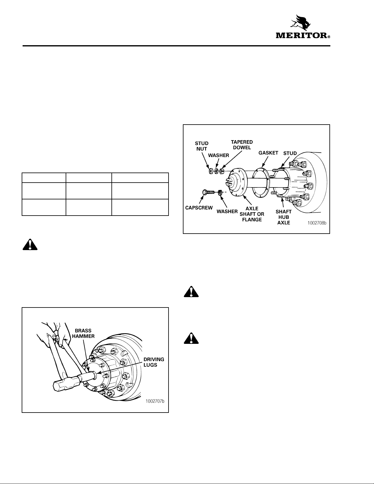
Brass Drift Method
2. Strike the end of the drift with a large hammer,
five to six pounds, and the axle shaft and
tapered dowels will loosen.
3. Mark each axle shaft before it is removed from
the axle assembly.
4. Remove the tapered dowels and separate the
axle shafts from the main axle hub assembly.
Figure 2.2.
Figure 2.2
WARNING
Do not strike the round driving lugs on the flange
of an axle shaft. Pieces can break off and cause
serious personal injury.
1. Hold a 1-1/2 -inch diameter brass drift or brass
hammer against the center of the axle shaft,
inside the round driving lugs. Figure 2.1.
Figure 2.1
5. Install a cover over the open end of each axle
assembly hub where an axle shaft was
removed.
Air Hammer Vibration Method
WARNING
Wear safe eye protection when using an air
hammer. When using power tools, axle
components can loosen and break off causing
serious personal injury.
CAUTION
Do not use a chisel or wedge to loosen the axle
shaft and tapered dowels. Using a chisel or wedge
can result in damage to the axle shaft, the gasket
and seal, and the axle hub.
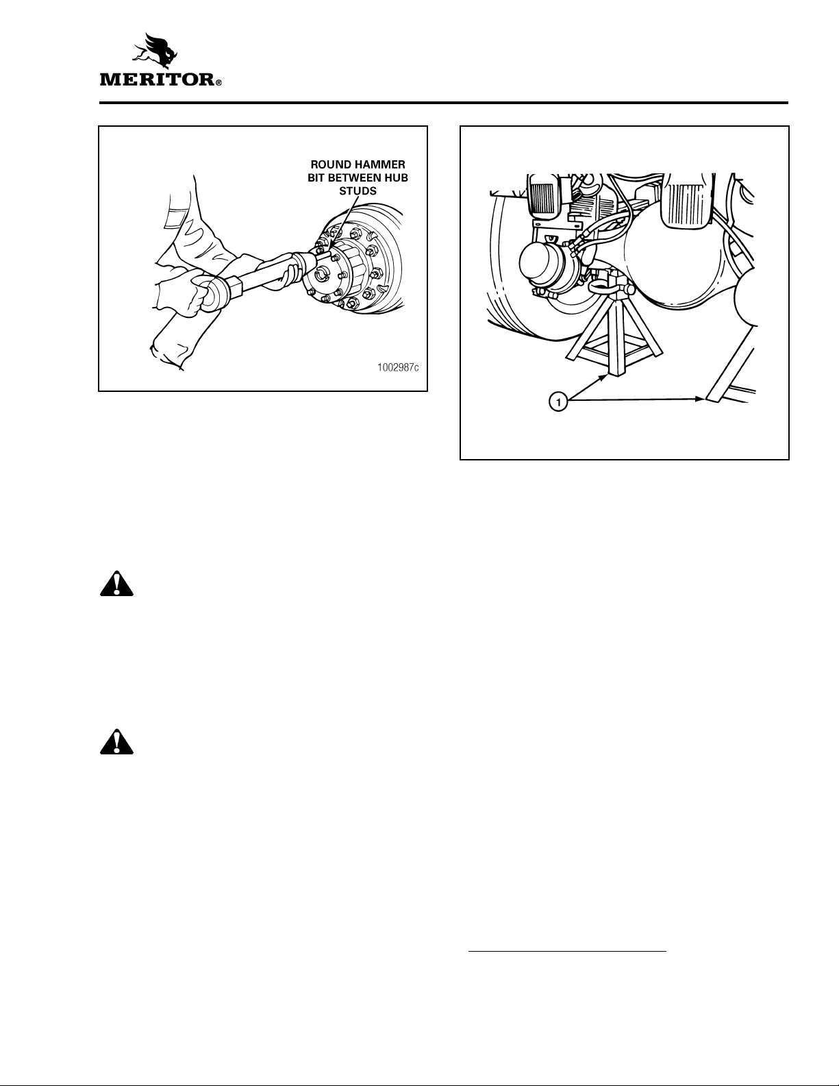
1. Use a round hammer bit and an air hammer to
loosen the tapered dowels and axle shaft.
2. Place the round hammer bit against the axle
shaft or flange between the hub studs. Operate
the air hammer at alternate locations between
the studs to loosen the tapered dowels and
axle shaft from the hub. Figure 2.3.
6
Section 2
Disassembly
Figure 2.3
3. Mark each axle shaft before it is removed from
the axle assembly.
4. Remove the tapered dowels and separate the
axle shaft from the main axle hub assembly.
Figure 2.2.
Remove Differential Carrier
from Axle Housing
WARNING
To prevent serious eye injury, always wear safe eye
protection when you perform vehicle maintenance
or service.
1. Raise the end of vehicle where the axle is
mounted. Use a jack or other lifting tool, and
place safety stands under each side of the axle.
Figure 2.4.
Figure 2.4
1 SAFETY STANDS
3. Remove the plug from bottom of axle housing
and drain lubricant from the assembly.
4. Disconnect the driveline universal joint from
the pinion input yoke or flange on the carrier.
Figure 2.5.
5. Remove the capscrews* and washers or stud
nuts* and washers from the flanges of both
axle shafts.*
6. Loosen the tapered dowels* if applicable, in
the axle flanges of both axle shafts using either
the Brass Drift or the Air Hammer Vibration
method. Refer to Axle Shaft Removal Methods
in this section.
WARNING
Park the vehicle on a level surface. Block the
wheels to prevent the vehicle from moving.
Support the vehicle with safety stands. Do not
work under a vehicle supported only by jacks.
Jacks can slip or fall over. Serious personal injury
can result.
2. Place jack stands under each spring seat of the
axle to hold vehicle in the raised position.
Figure 2.4.
*Some Meritor carriers do not have these
described parts.
7

Section 2
Disassembly
Figure 2.5
1 FULL ROUND BEARING CUPS
2 END YOKE
3 YOKE SADDLE
4 WELD YOKE
5 BEARING STRAP
6 CAPSCREWS
7 EASY-SERVICE BEARING CUPS
8 U-JOINT CROSS
9 SLIP YOKE
8
10 CAPSCREWS
11 END YO K E
12 WELD YOKE
13 SLIP YOKE
14 U-JOINT CROSS
15 CAPSCREWS
16 END YOKE
17 WELD YOKE
18 SLIP YOKE
19 U-JOINT CROSS
20 CAPSCREWS
21 END YOKE
22 SLIP YOKE
23 TUBING
24 U-JOINT CROSS
25 WELD YOKE
Carrier Removal from Axle
1. Place a hydraulic roller jack under the
differential carrier to support the assembly.
Figure 2.6.
2. Remove all but the top two carrier to housing
capscrews or stud nuts and washers.
3. Loosen the top two carrier-to-housing
fasteners and leave attached to the assembly.
The fasteners will hold the carrier in the
housing.
4. Loosen the differential carrier in the axle
housing. Use a leather mallet to hit the
mounting flange of carrier at several points.
5. After the carrier is loosened, remove the top
two fasteners.
Figure 2.6
Section 2
Disassembly
CAUTION
When using a pry bar be careful not to damage
the carrier or housing flange. Damage to these
surfaces will cause oil leaks.
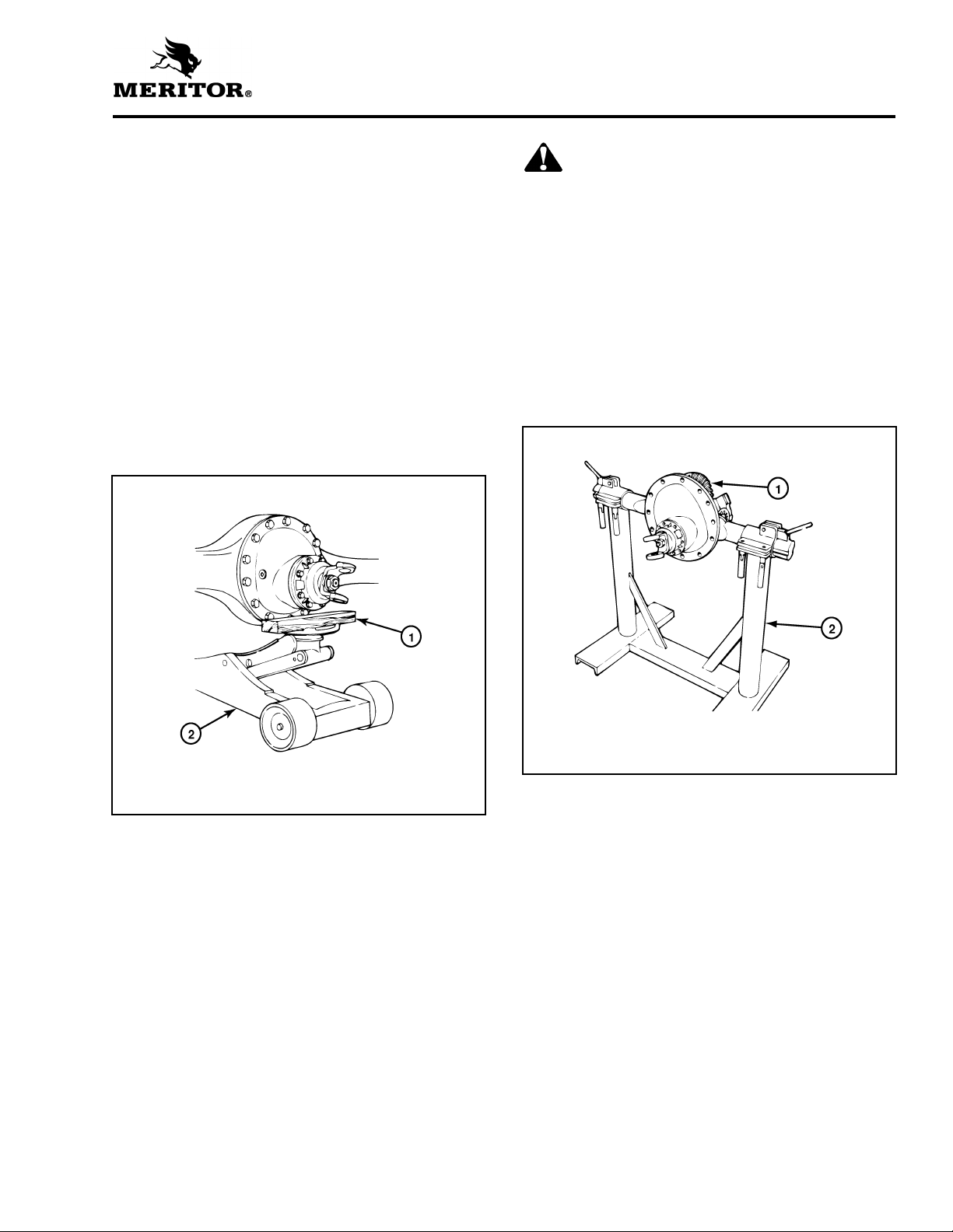
6. Carefully remove the carrier from the axle
housing using the hydraulic roller jack. Use a
pry bar that has a round end to help remove
the carrier from the housing.
7. Lift the differential carrier by the input yoke or
flange and place the assembly in a repair
stand. Figure 2.7. Use a lifting tool for this
procedure. Do not lift by hand. A carrier stand
can be built by referring to Figure 2.8.
Figure 2.7
1 WOOD BLOCK
2 ROLLER JACK
1 DIFFERENTIAL CARRIER
2 REPAIR STAND
9
Section 2
Disassembly
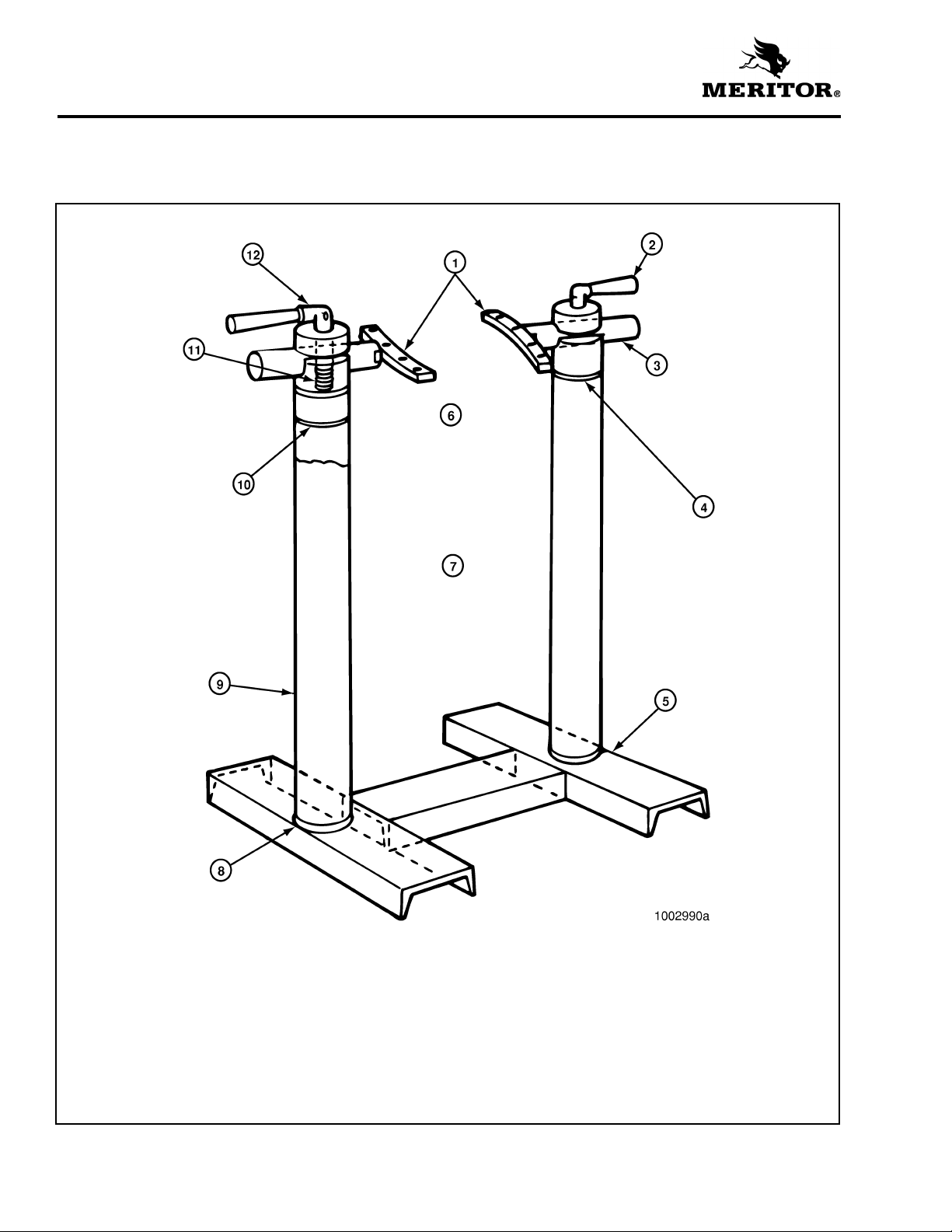
A carrier stand, part number J 3409-D is available
from Kent-Moore, Heavy-Duty Division, 28635
Mound Road, Warren, MI 48092.
Figure 2.8
1 PLATES 8' LONG x 3/4" THICK x 1-1/4" WIDE WITH A
TONGUE TO FIT SLOT IN BAR WELD PLATES TO BAR
2 HANDLE 7" LONG WITH SLOT IN ONE END TO FIT CLAMP
SCREW
3 BAR 2" DIAMETER x 9" LONG WITH ONE END SLOTTED
TO FIT PLATE
4 WELD ALL AROUND AFTER PRESSING PLUG IN PIPE
5 WELD
6 SHAPE AND SIZE OF HOLES TO FIT CARRIER
CARRIER STAND
10
7 23-1/2" CENTER TO CENTER OF PIPE
8 CHAMFER END OF PIPE FOR WELDING
9 4” DIAMETER PIPE
10 PLUG 4" DIAMETER x 7" LONG WITH ONE END TURNED
3" LONG TO FIT PIPE. DRILL 2" HOLE AND MILL 3/16"
WIDE SLOT 2" FROM TOP
11 SCREW 3-1/2" LONG x 5/8" DIAMETER WITH FLATS ON
END TO FIT HANDLE AND 2-1/2" LENGTH OF THREAD
ON OTHER END
12 DRILL 3/8" HOLE THROUGH HANDLE AND SCREW
Section 2
Disassembly
Remove the Differential and
Ring Gear from the Carrier
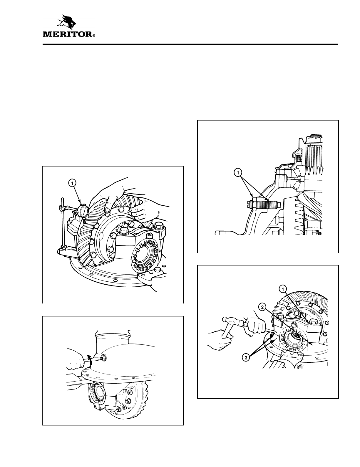
NOTE: Before working on the differential carrier,
inspect the hypoid gear set for damage. If
inspection shows no damage, the same gear set
can be used again. Measure the backlash of the
gear set and make a record of the dimension.
Figure 2.9. (Refer to “Ring Gear Backlash
Adjustment” in Section 5, Steps 1-5.) During
differential reassembly, adjust the backlash to the
original recorded dimension when the gear set is
installed into the carrier.
1. Loosen the jam nut* on the thrust screw*.
Figure 2.10.
Figure 2.9
2. Remove the thrust screw* and jam nut* from
the differential carrier. Figure 2.11.
3. Rotate the differential carrier in the repair stand
until the ring gear is at the top of the assembly.
4. Mark one carrier leg and bearing cap to
correctly match the parts during carrier
assembly. Mark the parts using a center punch
and hammer. Figure 2.12.
Figure 2.11
1 DIAL INDICATOR
Figure 2.10
1 THRUST SCREW AND JAM NUT
Figure 2.12
1 BEARING CAP
2 CARRIER LEG
3 MATCH MARKS
*Some Meritor carriers do not have these
described parts.
11

Section 2
Disassembly
5. Remove the cotter keys*, pins* or lock plates*
that hold the two bearing adjusting rings in
position. Use a small drift and hammer to
remove pins. Each lock plate is held in position
by two capscrews. Figure 2.13.
6. Remove the capscrews and washers that hold
the two bearing caps on the carrier. Each cap is
held in position by two capscrews and
washers. Figure 2.14.
7. Remove the bearing caps and bearing
adjusting rings from the carrier. Figure 2.15.
8. Safely lift the main differential and ring gear
assembly from the carrier. Place the assembly
on a work bench. Figure 2.16.
Figure 2.13
Figure 2.14
1 BEARING CAP
Figure 2.15
1 REMOVING COTTER KEY
2 REMOVING LOCK PLATE
*Some Meritor carriers do not have these
described parts.
12
1 BEARING CAP
2 BEARING ADJUSTING RING
Figure 2.16
Section 2
Disassembly
Disassemble the Differential
and Ring Gear Assembly
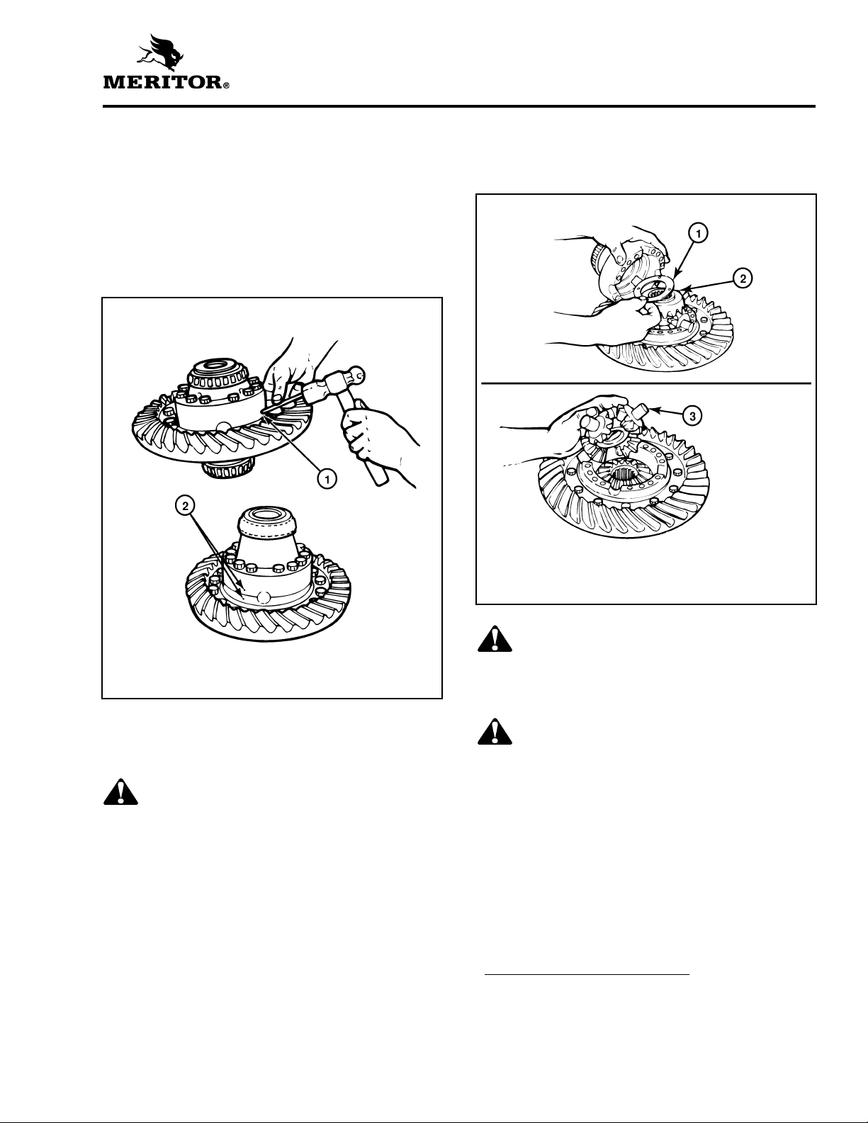
1. If the matching marks on the case halves of the
differential assembly are not visible, mark each
case half with a center punch and hammer. The
purpose of the marks is to match the plain half
and flange half correctly when you assemble
the carrier. Figure 2.17.
Figure 2.17
5. If the ring gear needs to be replaced, remove
the bolts*, nuts*, and washers* that hold the
gear to the flange case half.
Figure 2.18
1 MATCH MARKS
2 MATCH MARKS
2. Remove the capscrews* and washers* or
bolts*, nuts* and washers that hold the case
halves together.
WARNING
Use a brass or leather mallet for assembly and
disassembly procedures. Do not hit steel parts
with a steel hammer. Pieces of a part can break off
and cause serious personal injury.
3. Separate the case halves. If necessary, use a
brass, plastic or leather mallet to loosen the
parts.
4. Remove the differential spider (cross), four
pinion gears, two side gears and six thrust
washers from inside the case halves.
Figure 2.18.
1 THRUST WASHER
2 SIDE GEAR
3 SPIDER, PINIONS AND THRUST WASHERS
WARNING
Observe all warnings and cautions provided by the
press manufacturer to avoid damage to
components and serious personal injury.
CAUTION
Do not remove the rivets or rivet heads with a
chisel and hammer. Using a flat edge tool can
cause damage to the flange case.
6. If rivets* hold the ring gear to the flange case
half, remove the rivets as follows:
7. Carefully center punch each rivet head in the
center, on the ring gear side of the assembly.
*Some Meritor carriers do not have these
described parts.
13
Section 2
Disassembly
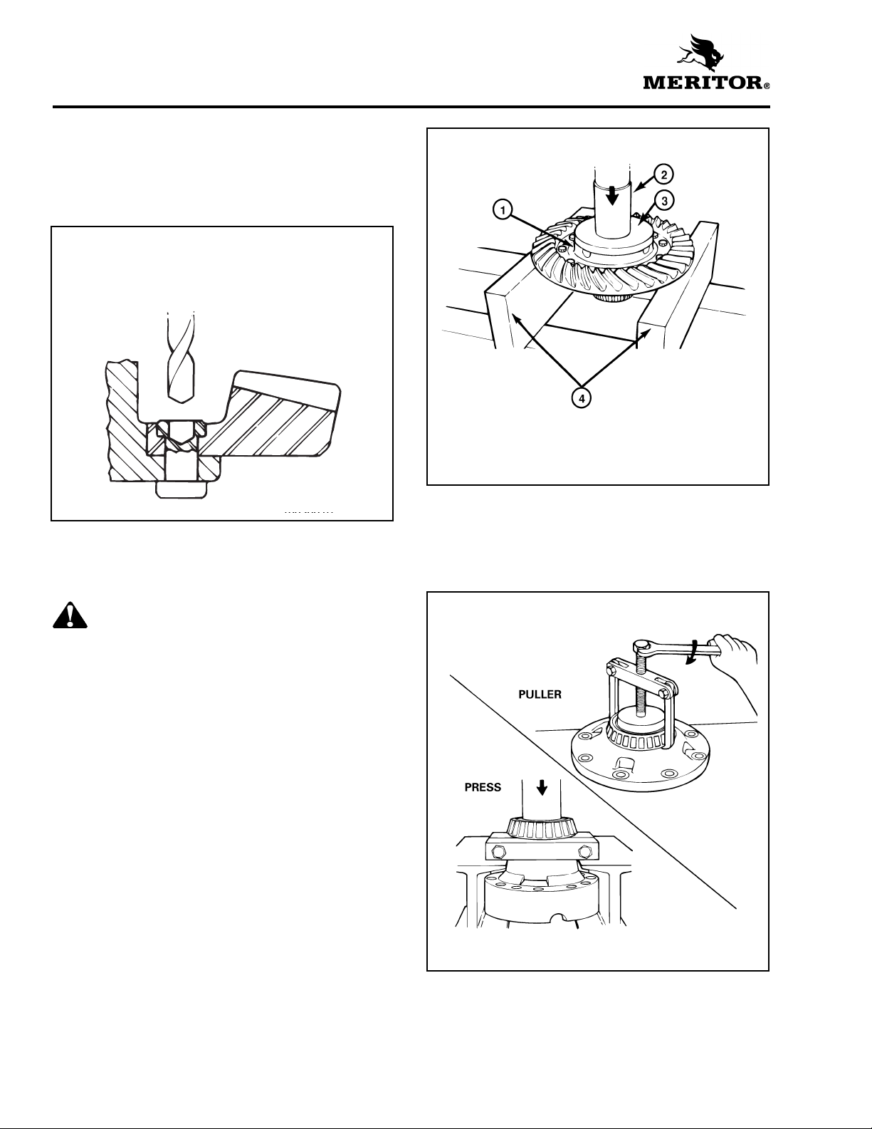
8. Drill each rivet head on the ring gear side of the
assembly to a depth equal to the thickness of
one rivet head. Use a drill bit that is 1/32 of an
inch smaller than the body diameter of the
rivets. Figure 2.19.
Figure 2.19
DRILLING RIVET FROM HEAD
9. Press the rivets through holes in the ring gear
and flange case half. Press from the drilled
rivet head.
Figure 2.20
1 CASE HALF
2 PRESS
3 PLATE
4 SUPPORTS
11. If the differential bearings need to be replaced,
remove the bearing cones from the case
halves. Use a bearing puller or press.
Figure 2.21.
WARNING
Observe all warnings and cautions provided by the
press manufacturer to avoid damage to
components and serious personal injury.
10. Separate the case half and ring gear using a
press. Support the assembly under the ring
gear with metal or wood blocks and press the
case half through the gear. Figure 2.20.
Figure 2.21
14
Section 2
Disassembly
Remove the Drive Pinion and
Bearing Cage from Carrier
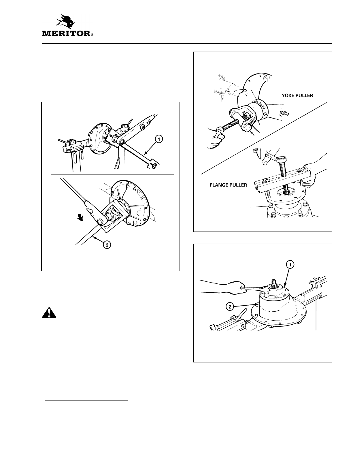
1. Fasten a flange bar to the input yoke or flange.
When the nut is removed, the bar will hold the
drive pinion in position. Figure 2.22.
Figure 2.22
Figure 2.23
1 FLANGE BAR
2 YOKE BAR
2. Remove the nut and washer* from the drive
pinion. Figure 2.22.
3. Remove the yoke or flange bar.
CAUTION
Do not use a hammer or mallet to loosen and
remove the yoke or flange. A hammer or mallet
can damage the parts and cause driveline runout,
or driveline imbalance problems after carrier to
driveline assembly.
4. Remove the yoke or flange from the drive
pinion. If the yoke or flange is tight on the
pinion, use a puller for removal. Figure 2.23.
5. Remove the capscrews and washers that hold
the bearing cage in the carrier. Figure 2.24.
*Some Meritor carriers do not have these
described parts.
Figure 2.24
1 BEARING CAGE
2 CARRIER
15
Section 2
Disassembly
WARNING
Use a brass or leather mallet for assembly and
disassembly procedures. Do not hit steel parts
with a steel hammer. Pieces of a part can break off
and cause serious personal injury.
CAUTION
Do not use a pry bar to remove the bearing cage
from the carrier. A pry bar can damage the bearing
cage, shims and carrier.
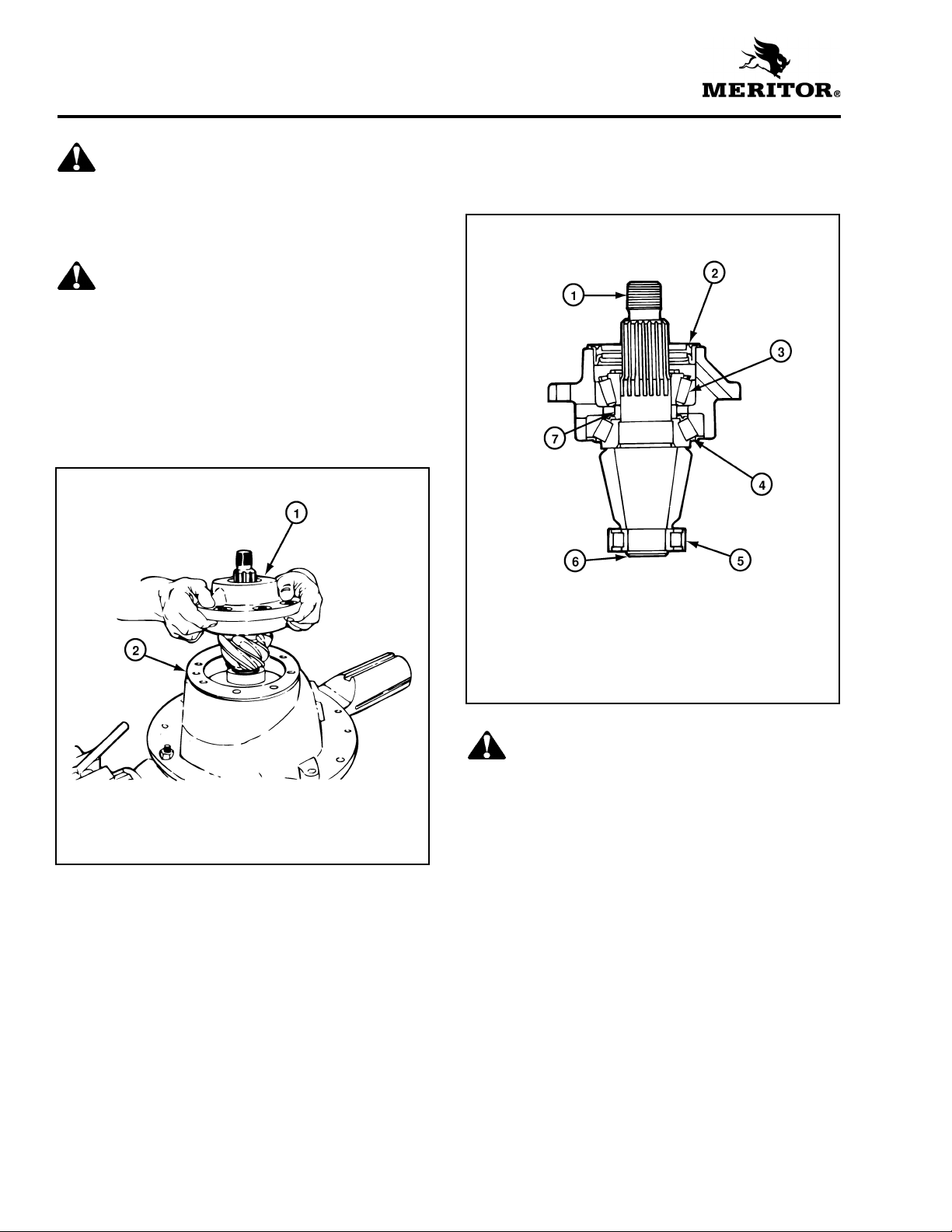
6. Remove the drive pinion, bearing cage and
shims from the carrier. If the bearing cage is
tight in the carrier, hit the bearing cage at
several points around the flange area with a
leather, plastic or rubber mallet. Figure 2.25.
Figure 2.25
Disassemble the Drive Pinion
and Bearing Cage
Figure 2.26
1 DRIVE PINION
2 OIL SEAL
3 OUTER BEARING (CUP AND CONE)
4 INNER BEARING (CUP AND CONE)
5 SPIGOT BEARING
6 SNAP RING
7 BEARING SPACER
1 DRIVE PINION AND BEARING CAGE
2 SHIMS
7. If the shims are in good condition, keep the
shims together for use later when the carrier is
assembled.
8. If shims are to be discarded because of
damage, first measure the total thickness of
the pack. Make a note of the dimension. The
dimension will be needed to calculate the
depth of the drive pinion in the carrier when
the gear set is installed.
16
WARNING
Observe all warnings and cautions provided by the
press manufacturer to avoid damage to
components and serious personal injury.
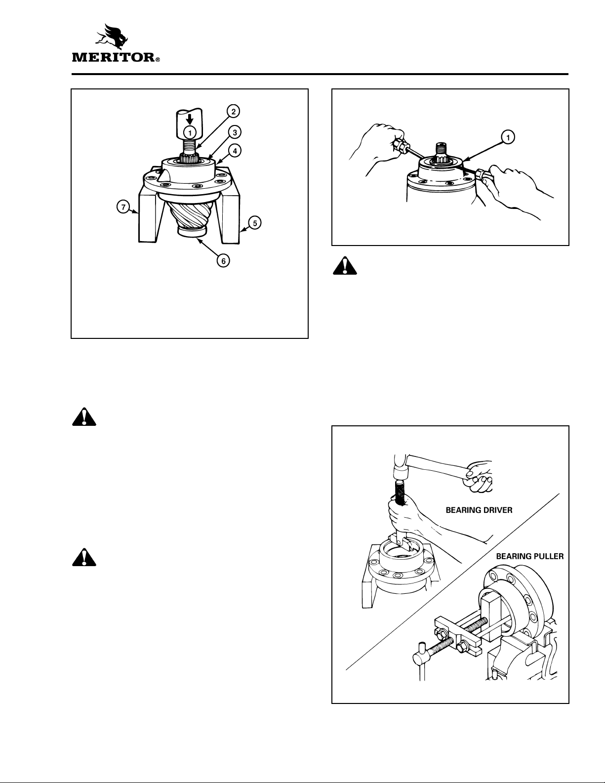
1. Place the drive pinion and bearing cage in a
press. The pinion shaft must be toward the top
of the assembly. Figure 2.27.
Section 2
Disassembly
Figure 2.27
1 PRESS
2 DRIVE PINION
3 OIL SEAL
4 BEARING CAGE
5 SUPPORT
6 SPIGOT BEARING
7 SUPPORT
2. Support the bearing cage under the flange area
with metal or wood blocks. Figure 2.27.
3. Press the drive pinion through the bearing
cage. Figure 2.27.
Figure 2.28
1 OIL SEAL
WARNING
Observe all warnings and cautions provided by the
press manufacturer to avoid damage to
components and serious personal injury.
6. If the pinion bearings need to be replaced,
remove the inner and outer bearing cups from
the inside of cage. Use a press and sleeve,
bearing puller, bearing driver or a small drift
hammer. The type of tool used depends on the
design of the bearing cage. Figure 2.29.
When a press is used, support the bearing cage
under the flange area with metal or wood blocks.
WARNING
Use a brass or leather mallet for assembly and
disassembly procedures. Do not hit steel parts
with a steel hammer. Pieces of a part can break off
and cause serious personal injury.
NOTE: The inner bearing cone and bearing spacer
will remain on the pinion shaft.
4. If a press is not available, use a leather, plastic
or rubber mallet to drive the pinion through
the bearing cage.
CAUTION
Be careful when removing the seal. Do not
damage the wall of bore. Damage to the bore wall
can result in oil leaks.
NOTE: When the oil seal has been removed,
always replace it with a new triple-lip (main) seal
during component reassembly.
5. If the pinion oil seal is mounted directly in the
outer bore of the bearing cage, remove the
seal at this time.
Be careful that you do not damage the
mounting surfaces of the bearing cage.
Figure 2.28.
Figure 2.29
17
Section 2
Disassembly
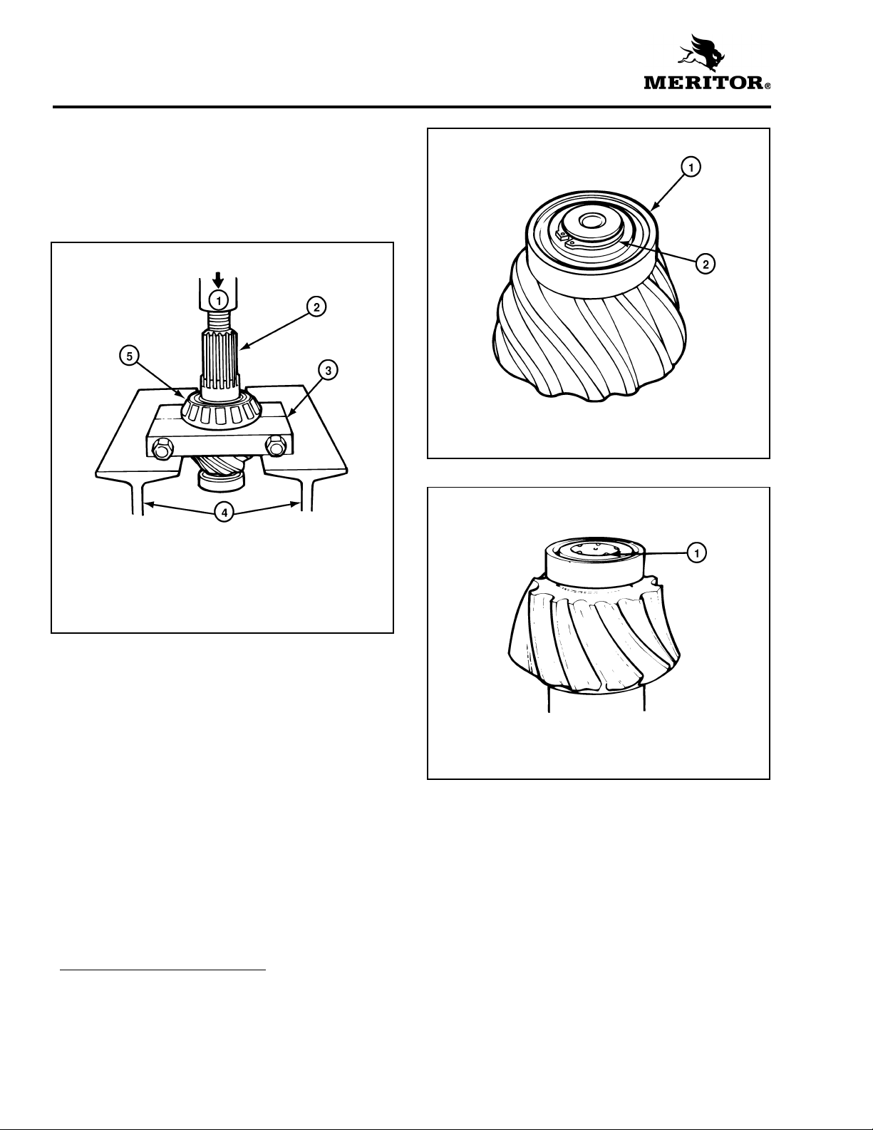
7. If the pinion bearings need to be replaced,
remove the inner bearing cone from the drive
pinion with a press or bearing puller. The
puller MUST fit under the inner race of the
cone to remove the cone correctly without
damage. Figure 2.30.
Figure 2.30
Figure 2.31
1 SPIGOT BEARING
2 SNAP RING
Figure 2.32
1 PRESS
2 DRIVE PINION
3 BEARING PULLER
4 SUPPORTS
5 INNER BEARING CONE
8. If the spigot bearing needs to be replaced,
place the drive pinion in a vise. Install a soft
metal cover over each vise jaw to protect the
drive pinion.
9. Remove the snap ring* from the end of drive
pinion with snap ring pliers that expand.
Figure 2.31.
NOTE: Some spigot bearings are fastened to
the drive pinion with a special peening tool.
Figure 2.32.
1 PEENING POINTS
*Some Meritor carriers do not have these
described parts.
18
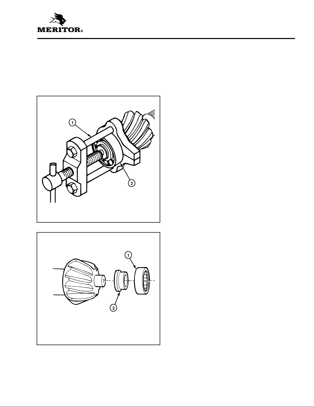
10. Remove the spigot bearing from the drive
pinion with a bearing puller. Figure 2.33.
NOTE: Some spigot bearings are a two-piece
assembly. Remove the inner race from the pinion
with a bearing puller. Remove the outer race/roller
assembly from carrier with a drift or a press.
Figure 2.34.
Figure 2.33
Section 2
Disassembly
1 BEARING PULLER
2 SPIGOT BEARING
Figure 2.34
1 REMOVE OUTER RACE AND ROLLER ASSEMBLY FROM
CARRIER
2 REMOVE INNER RACE FROM PINION
19
Section 3
Preparing the Parts for Assembly
Section 3Preparing the Parts for Assembly
Cleaning Ground and
Polished Parts
WARNING
To prevent serious eye injury, always wear safe eye
protection when you perform vehicle maintenance
or service.
Solvent cleaners can be flammable, poisonous and
cause burns. Examples of solvent cleaners are
carbon tetrachloride, emulsion-type cleaners and
petroleum-based cleaners. To avoid serious
personal injury when you use solvent cleaners,
you must carefully follow the manufacturer's
product instructions and these procedures:
앫 Wear safe eye protection.
앫 Wear clothing that protects you skin.
앫 Work in a well-ventilated area.
앫 Do not use gasoline, or solvents that contain
gasoline. Gasoline can explode.
앫 You must use hot solution tanks or alkaline
solutions correctly. Follow the manufacturer's
instructions carefully.
CAUTION
Use only solvent cleaners to clean ground or
polished metal parts. Hot solution tanks or water
and alkaline solutions will damage parts. Isopropyl
alcohol, kerosene or diesel fuel can be used for this
purpose. If required, use a sharp knife to remove
gasket material from parts. Be careful not to
damage the ground or polished surfaces.
1. Use a cleaning solvent to clean ground or
polished parts or surfaces. Kerosene or diesel
fuel oil can be used for this purpose. Do not
use gasoline.
2. Use a tool with a flat blade, if required, to
remove sealant material from parts. Be careful
not to damage the polished or smooth
surfaces.
3. Do not clean ground or polished parts with
water or steam. Do not immerse ground or
polished parts in a hot solution tank or use
strong alkaline solutions for cleaning, or the
smooth sealing surface may be damaged.
Cleaning Rough Parts
WARNING
Solvent cleaners can be flammable, poisonous and
cause burns. Examples of solvent cleaners are
carbon tetrachloride, emulsion-type cleaners and
petroleum-based cleaners. To avoid serious
personal injury when you use solvent cleaners,
you must carefully follow the manufacturer's
product instructions and these procedures:
앫 Wear safe eye protection.
앫 Wear clothing that protects you skin.
앫 Work in a well-ventilated area.
앫 Do not use gasoline, or solvents that contain
gasoline. Gasoline can explode.
앫 You must use hot solution tanks or alkaline
solutions correctly. Follow the manufacturer's
instructions carefully.
1. Clean rough parts with the same method as
cleaning ground and polished parts.
2. Rough parts can be cleaned in hot solution
tanks with a weak or diluted alkaline solution.
3. Parts must remain in hot solution tanks until
heated and completely cleaned.
4. Parts must be washed with water until all
traces of the alkaline solution are removed.
Cleaning Axle Assemblies
1. A complete axle assembly can be steam
cleaned on the outside to remove dirt.
2. Before the axle is steam cleaned, close or place
a cover over all openings in the axle assembly.
Examples of openings are breathers or vents in
air chambers.
Drying Parts After Cleaning
CAUTION
Damage to bearings can result when they are
rotated and dried with compressed air.
1. Parts must be dried immediately after cleaning
and washing.
2. Dry the parts using soft, clean paper or cloth
rags.
20
3. Except for bearings, parts can be dried with
compressed air.
 Loading...