

Page 1
A subsidiary of Alanco Technologies, Inc.
SecurStor Astra ES
Administration Guide
Revision: 1.0
Contact Information
Excel Meridian Data, Inc.
3220 Commander Drive Ste 101
Carrollton, TX 75006-2564
Toll Free: (800) 995-1014
Phone: (972) 980-7098
Fax: (972) 980-0375
sales@emdstorage.com
support@emdstorage.com
http://www.emdstorage.com
Page 2

Copyright ©2007
This guide and any accompanying software and firmware are copyrighted. No parts of this
publication may be reproduced, stored on a retrieval system, or transmitted, in any form or
by any means, electronic, mechanical, photocopy, recording, or otherwise, without prior
written consent except for copies retained by the purchaser for backup purposes. All rights
Reserved.
Notice
We make no warranties with respect to this documentation either express or implied and
provide it "as is". This includes but is not limited to any implied warranties of
merchantability and fitness for a particular purpose. The information in this document is
subject to change without notice. We assume no responsibility for any errors that may
appear in this document. The manufacturer shall not be liable for any damage, or for the
loss of information resulting from the performance or use of the information contained
herein.
Trademarks
Product names used herein are for identification purposes only and may be the trademarks
of their respective companies. All trademarks or registered trademarks are properties of
their respective owners.
Page 3

(this page intentionally left blank)
SECURSTOR ASTRA ES 3
Page 4

Table of Contents
Chapter 1: Introduction to Astra ES ....................................................................... 7
About This Manual ................................................................................................... 7
Astra ES Overview ................................................................................................... 8
Architectural Description .......................................................................................... 9
Specifications ........................................................................................................ 10
Chapter 2: Astra ES Installation ........................................................................... 13
Unpacking the Astra ES .......................................................................................... 13
Mounting Astra ES in a Rack ................................................................................... 14
Installing Disk Drives ............................................................................................. 15
Making Management and Data Connections .............................................................. 16
Fibre Channel Host ............................................................................................. 16
Serial Attached SCSI Host.................................................................................... 18
Connecting the Power ............................................................................................ 20
Chapter 3: Management with Astra GUI
Logging into Astra GUI ........................................................................................... 21
Selecting a Language ............................................................................................. 22
Perusing the Interface ............................................................................................ 22
Logging out of Astra GUI ........................................................................................ 23
Working with the Storage Network .......................................................................... 24
Working with Subsystems ....................................................................................... 24
Managing Users ..................................................................................................... 30
Managing the Network Connection ........................................................................... 33
Managing Fibre Channel Connections ....................................................................... 34
Managing SAS Connections ..................................................................................... 37
Managing Storage Services ..................................................................................... 39
Managing Software Services ................................................................................... 40
Exporting the User Database ................................................................................... 45
Updating the Firmware ........................................................................................... 47
Restoring Factory Defaults ...................................................................................... 47
Clearing Statistics .................................................................................................. 47
Shutting Down the Subsystem ................................................................................ 48
Restarting the Subsystem ....................................................................................... 48
Managing Controllers ............................................................................................. 48
Managing Enclosures ............................................................................................. 51
Managing Physical Drives ....................................................................................... 54
Managing Disk Arrays ............................................................................................ 57
Managing Logical Drives ......................................................................................... 65
Managing Spare Drives .......................................................................................... 69
Working with the Logical Drive Summary ................................................................. 72
Chapter 4: Maintenance ....................................................................................... 73
Updating the Firmware ........................................................................................... 73
Replacing a Power Supply ....................................................................................... 74
Replacing a Cooling Unit Blower .............................................................................. 75
Replacing a Cache Battery ...................................................................................... 77
Replacing a RAID Controller .................................................................................... 78
Chapter 5: Technology Background ...................................................................... 81
Introduction to RAID .............................................................................................. 81
Choosing a RAID Level ........................................................................................... 92
Choosing Stripe Size .............................................................................................. 95
Choosing Sector Size ............................................................................................. 95
................................................................ 21
4 EXCEL MERIDIAN DATA
Page 5

Cache Policy ......................................................................................................... 96
LUN Affinity .......................................................................................................... 96
Capacity Coercion .................................................................................................. 97
Initialization .......................................................................................................... 98
Hot Spare Drive(s) ................................................................................................ 98
Partition and Format the Logical Drive ...................................................................... 98
RAID Level Migration ............................................................................................. 99
Media Patrol ........................................................................................................ 100
Predictive Data Migration (PDM) ............................................................................ 101
Transition ........................................................................................................... 101
Chapter 6: Troubleshooting ................................................................................ 105
Beep Tones ......................................................................................................... 105
LEDs Display ....................................................................................................... 105
Astra Web GUI Reports a Problem ......................................................................... 108
Event Notification Response .................................................................................. 110
Critical & Offline Disk Arrays ................................................................................. 130
Incomplete Array................................................................................................. 132
Physical Drive Problems ....................................................................................... 132
Enclosure Problems ............................................................................................. 134
Appendix A: SNMP MIB Files .............................................................................. 137
Appendix B: Adding a Second Controller ............................................................ 139
SECURSTOR ASTRA ES 5
Page 6

(this page intentionally left blank)
6 EXCEL MERIDIAN DATA
Page 7

Chapter 1: Introduction to Astra ES
Note
A Note provides helpful information such as hints or alternative
ways of doing a task.
Important
An Important calls attention to an essential step or point required
to complete a task. Important items include things often missed.
Caution
A Caution informs you of possible equipment damage or loss of
data and how to avoid them.
Warning
A Warning notifies you of probable equipment damage or loss of
data, or the possibility of physical injury, and how to avoid them.
This chapter covers the following topics:
• About this Manual
• Astra ES Overview
• Architectural Description
• Specifications
Thank you for purchasing the SecurStor Astra ES disk array subsystem from Excel Meridian Data.
About This Manual
This Product Manual describes how to setup, use and maintain the Astra ES disk array subsystem. It also
describes how to use the embedded Web-based Astra ES Management GUI software.
Note these four levels of notices:
SECURSTOR ASTRA ES 7
Page 8

RAID Controller 1
Power Supply 1 Power Supply 2Cooling Unit 1
with Battery
Cooling Unit 2
with Battery
RAID Controller 2
Controller 1
Power Supply 1 Power Supply 2Cooling Unit 1
with Battery
Cooling Unit 2
with Battery
Controller 2
Astra ES Overview
Astra ES provides data storage solutions for applications where high performance and data protection are
required. The failure of any single drive will not affect data integrity or accessibility of the data in a RAID
protected logical drive.
A defective drive may be replaced without interruption of data availability to the host computer. If so configured, a
hot spare drive will automatically replace a failed drive, securing the fault-tolerant integrity of the logical drive.
The self-contained hardware-based RAID logical drive provides maximum performance in a compact external
chassis.
Figure 1: Astra ES (FC Host) rear view
Figure 2: Astra ES (SAS Host) rear view
8 EXCEL MERIDIAN DATA
Page 9

Architectural Description
The Astra ES is a Fibre Channel or Serial Attached SCSI (SAS) host, SAS+SATA disk, subsystem suitable for
Direct Attached Storage (DAS), Storage Area Network (SAN), and Expanded Storage.
Only hard disk drives from Excel Meridian Data are approved for use in this solution.
All enclosures include a mid-plane, RAID controller, power and cooling units, and enclosure processor all in one
cable-less chassis design. Multiple fans and power supplies provide redundancy to ensure continued usage
during component failure. The RAID controller is hardware based and controls all logical drive functions
transparently to the host system. Astra ES appears to the computer’s operating system as a standard SCSI drive
or drives.
Features and Benefits
Highlights
• Dual channel active/active, failover/failback RAID controllers
• 12 hot-swappable drive bays in a robust 2U rackmount chassis with redundant, hot-swappable power and
cooling modules
• Supports for Serial Attached SCSI (SAS) and Serial ATA (SATA) 3 Gb/s drives simultaneously in the same
system—choose the drive that is best suited to your application
• Dual Fibre Channel and SAS host ports provide high-availability SAN and cluster-friendly platform
• JBOD expansion support through a 3 Gb/s SAS x4 port—up to four Astra ES JBOD systems
• Simplified remote management with a comprehensive embedded web-based management via Ethernet—
Astra ES Management GUI.
• Five years complete system limited warranty including email and phone support with highly experienced
technical support technicians.
• Resilient data protection features such as Predictive Data Migration™ and PerfectRAID™ provide rock solid
data protection
• LUN Mapping and Masking bring flexibility for multiple application and OS support on the same storage
subsystem
• Open architecture, industry’s most comprehensive support for SAS and SATA hard drives and standardsbased management interfaces
• Support for the industry standard Disk Data Format (DDF from SNIA) ensures interoperability and drive
roaming even among different RAID vendors
• Compatible with leading SAS hard drives, host bus adapters and RAID controllers
Subsystem and Controller Features
Controllers: Dual-controller configuration or single-controller configuration, upgradeable to dual. Dual-controller
subsystems feature Active/Active, Failover/Failback.
Drive Support: Up to twelve 3.5" x 1" hard disk drives: SAS 3Gb/s, SATA II 3Gb/s and 1.5Gb/s. SATA drives
require a MUX Adapter in dual I/O module configuration (dual-controller) subsystems.
Supports any mix of SAS and SATA II 3Gb/s or 1.5Gb/s drives simultaneously in the same system. Staggered
physical drive spin-up.
External I/O Ports (per controller): Dual 4-Gb Fibre Channel host port; One external 3 Gb/s SAS x4 ports for
JBOD expansion (up to four Astra ES JBOD Systems).
Data Cache: Shared 512 MB predictive data cache (expandable to 2 GB); Automatic write cache destaging; 72hour battery backup (for 512 MB cache).
Command Queue Depth: 512 commands per Astra ES system (up to 1024 commands with 512 MB memory).
Operational Features
RAID Levels: RAID 0, 1, 1E, 5, 6, 10, 50, and 60 – Any combination of these RAID levels can exist at the same
time.
SECURSTOR ASTRA ES 9
Page 10

Configurable RAID stripe size: 64 KB, 128 KB, 256 KB, 512 KB, and 1 MB stripe size per logical drive.
Background task priority tuning: Adjustment of minimum I/O reserved for server use during all background tasks.
Hot spares: Multiple global or dedicated hot-spare drives with revert option.
Maximum LUNs per subsystem: 256 in any combination of RAID levels.
Maximum LUNs per array: 32 logical drives (LUNs). Supports LUN carving by allowing an array to be divided into
multiple logical drives. Supports out-of-order logical drive deletion and re-creation.
Max LUNs per Target ID: Up to 256, depending on host side driver and operating system.
LUN Masking and Mapping: Supports multiple hosts.
Background Activities: Media Patrol, background synchronizing, disk array rebuild, Redundancy Check, SMART
condition pooling, Online Capacity Expansion (OCE), RAID Level Migration (RLM). Includes priority control, rate
control, and watermarking per BGA in disk and NVRAM.
Foreground Activities: Disk array initialization.
Physical Drive Error Recovery: Predictive Data Migration (PDM), replaces un-healthy disk member in array, while
maintaining normal array status during the data transition. Bad Sector Mapping, Media Patrol, SMART, Hard/Soft
Reset to recover HD from bad status, HD Power-control to recover HD from hung status.
Array Error Recovery: Data recovery from bad sector or failed HD for redundant RAID, RAID 5/6 inconsistent
data Prevent (Write Hole Table), Data content Error Prevent (Read/Write Check Table) NVRAM event logging.
SCSI Commands: Supports extensive SCSI command set equivalent to SCSI/FC hard disk drives. Variable
sector size (512 byte to 4 KB) to break OS 2TB limitation. 16 byte CDB support for 64-bit LBA addressing.
Management
Supported Operating Systems: Windows 2000 Server, Windows 2003 Server, Linux (Red Hat, SuSE), Macintosh
OS X, Solaris.
Management Tools: Astra ES Management GUI via out-of-band Ethernet. OS independent, localized in multiple
languages, SSL Security support. Standard Management Protocols: SNMP
RAID Creation: Automatic, Express, and Advanced configuration support for novice to skilled users.
Management Protocols: Embedded web server and management support—no host agent needed. Ethernet, RJ-
11 serial port, SNMP, SSL, Telnet, Email.
Specifications
Current (maximum): 8 A @ 100 VAC or 4 A @ 240 VAC Current rating with two power cords.
Power Consumption: 78.67 W (not including disk drives).
Power Supply: Dual 400W, 100-240 VAC auto-ranging, 50-60 Hz, dual hot swap and redundant.
Operating Temperature: 5° to 40ûC operational (-40° to 60ûC non-operational)
Relative Humidity: Maximum 95 percent.
Vibration: Random, 0.21 grms, 5-500Hz, 30Mins, X, Y, Z axis.
Dimensions (H x W x D): 8.8 x 44.4 x 56.1 cm (3.5 x 17.5 x 22.1 in)
Net Weight (subsystem only): 22 kg (49 lb) without drives, 28 kg (62 lb) with 12 drives, assuming 0.5 kg (1.1 lb)
per drive.
Gross Weight (including carton): 30 kg (66 lb) without drives.
Safety: CE, FCC Class A, cUL.
10 EXCEL MERIDIAN DATA
Page 11

Warranty and Support
Warranty: Five years complete system limited warranty. Contact Excel Meridian Data for details.
Support: Email and phone support.
FCC Statement
This device complies with Part 15 of the FCC Rules. Operation is subject to the following two conditions: (1) this
device may not cause harmful interference, and (2) this device must accept any interference received, including
interference that may cause undesired operation.
CE Statement
Warning: This is a class A product. In a domestic environment this product may cause radio interference in which
case the user may be required to take adequate measures.
SECURSTOR ASTRA ES 11
Page 12

(this page intentionally left blank)
12 EXCEL MERIDIAN DATA
Page 13
Chapter 2: Astra ES Installation
• Astra ES Unit
• Quick Start Guide
• This Administration Guide
• Rail kit
• RJ11-to-DB9 serial data cable
• 10ft CAT6 RJ45 network cable(s)
• 5ft Power cords (4) (2 US and 2
European)
• CD with AstraPath, Product Manual
and Quick Start Guide
Warning
The electronic components within the Astra ES disk array are
sensitive to damage from Electro-Static Discharge (ESD).
Observe appropriate precautions at all times when handling the
Astra ES or its subassemblies.
Important
Use the following categories of network cables with Astra ES:
• Cat 6, preferred (included)
• Cat 5E, minimum
This chapter covers the following topics:
• Unpacking the Astra ES (below)
• Mounting in a rack
• Installing disk drives
• Making management connections
• Connecting power
Unpacking the Astra ES
The Astra ES box contains the following items:
SECURSTOR ASTRA ES 13
Page 14

Mounting Astra ES in a Rack
Cautions
• At least two persons are required to safely lift, place, and
attach the Astra ES enclosure into a rack system.
• Do not lift or move the Astra ES enclosure by the handles,
power supplies or the controller units. Hold the enclosure
itself.
• Do not install the Astra ES enclosure into a rack without rails
to support the enclosure.
The subsystem installs in the rack using the supplied mounting rails.
To install the Astra ES enclosure into a rack with the supplied mounting rails:
1. Check the fit of the mounting rails in your rack system.
2. Please note that the plates are already attached to each side of the chassis.
3. Confirm the screws are properly tightened for each of the 2 plates on the chassis.
4. Slide one of the rails over the plate on one side of the enclosure.
The rail is designed to slide freely over the plate.
5. Attach a four-hole flange to the rail, with the flange toward the front (disk drive end) of the enclosure.
Install four rail adjustment screws (included) through the flange into the rail.
6. Attach a two-hole flange to the rail, with the flange toward the back (connector end) of the enclosure.
Install four rail adjustment screws (included) through the flange into the rail.
7. Repeat steps 4 through 6 to attach the other rail and flanges to the enclosure.
8. Place the enclosure with mounting rails into your rack system.
9. Attach the four-hole flanges to the inside of the rack’s front post, using the attaching screws from your rack
system.
10. Attach the two-hole flanges to the inside of the rack’s rear post, using the attaching screws from your rack
system.
11. Square the rails in the rack.
12. Tighten the adjustment screws and the attaching screws.
14 EXCEL MERIDIAN DATA
Page 15
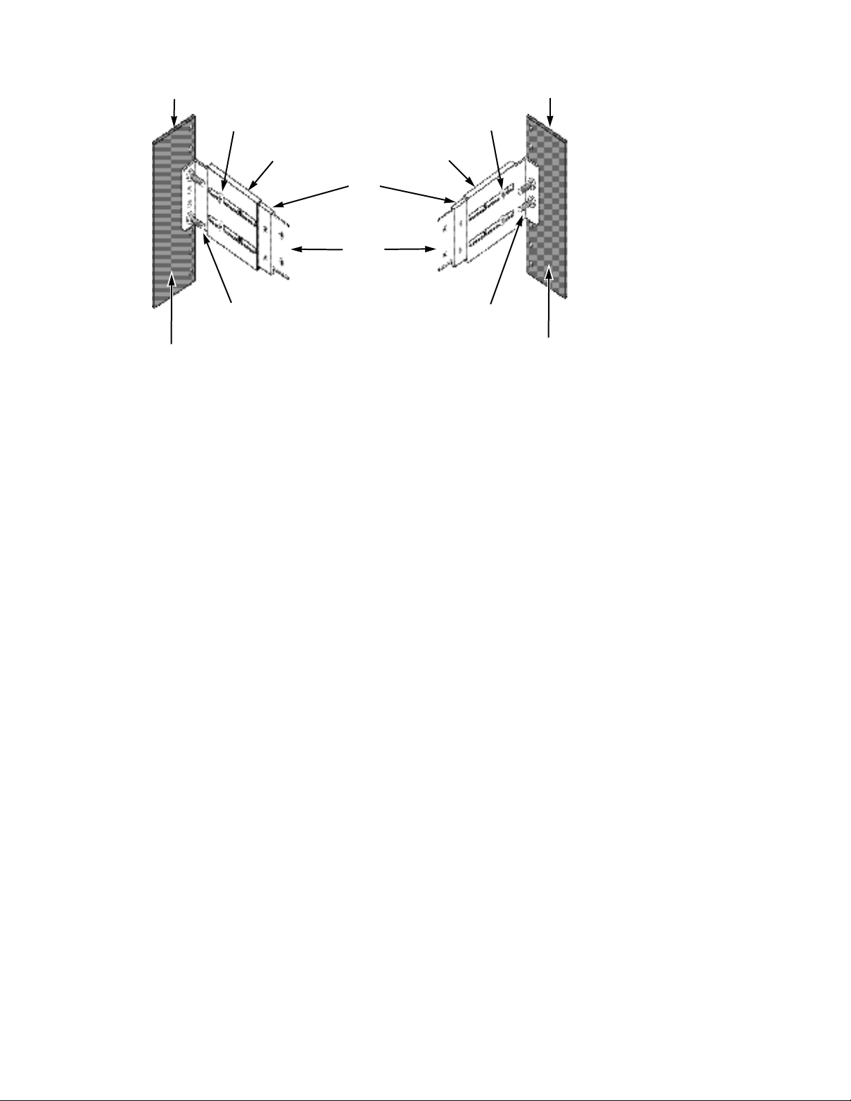
Inside of post
Rack f ront post
Rail attaching screw
(not included)
Rail adjustment screw
Rail
Rail attaching screw
(not included)
Inside of post
Rack back post
Plate
Front flange
Rail adjustment screw
Rear flange
Figure 3: Rackmount assembly
Installing Disk Drives
Your solution is sold with SAS or SATA (or a combination of both) hard disk drives. Excel Meridian Data will not
support any solution populated with disk drives not purchased through Excel Meridian Data.
The hard disk drives are shipped in specially designed packaging and are not pre-installed into the enclosure.
You will need to unpack them from their cartons and install them after you have racked the enclosure and
secured it. Do not install the drives prior to securing the enclosure in the rack.
Drive Slot Numbering
You can install any disk drive into any slot in the enclosure. The diagram below shows how Astra ES drive slots
are numbered. Slot numbering is also reflected in the web user interface.
Install all of the drive carriers into the Astra ES enclosure to ensure proper airflow, even if you not all
carriers are populated with disk drives.
MUX Adapter
If your Astra ES has dual controllers—Fibre Channel or SAS—and you plan to install SATA drives, you must
install a MUX adapter with each SATA drive. MUX adapters are available from Excel Meridian Data.
SECURSTOR ASTRA ES 15
Page 16
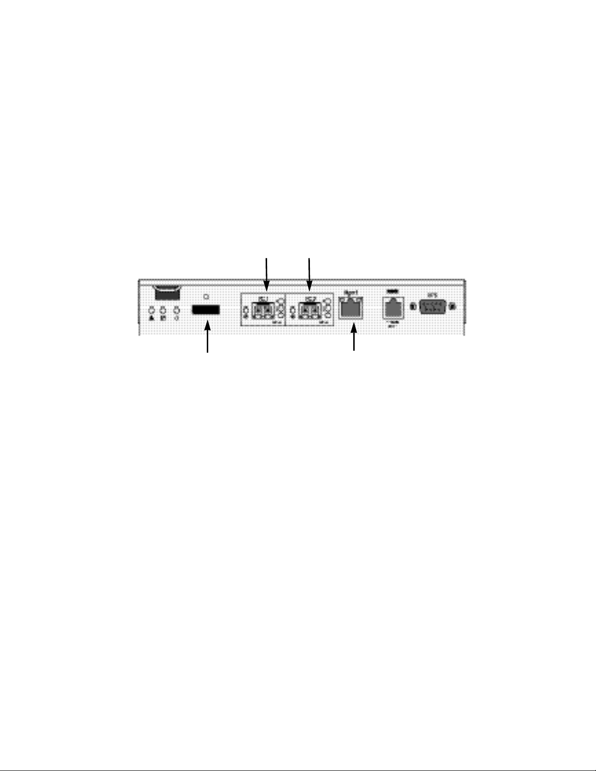
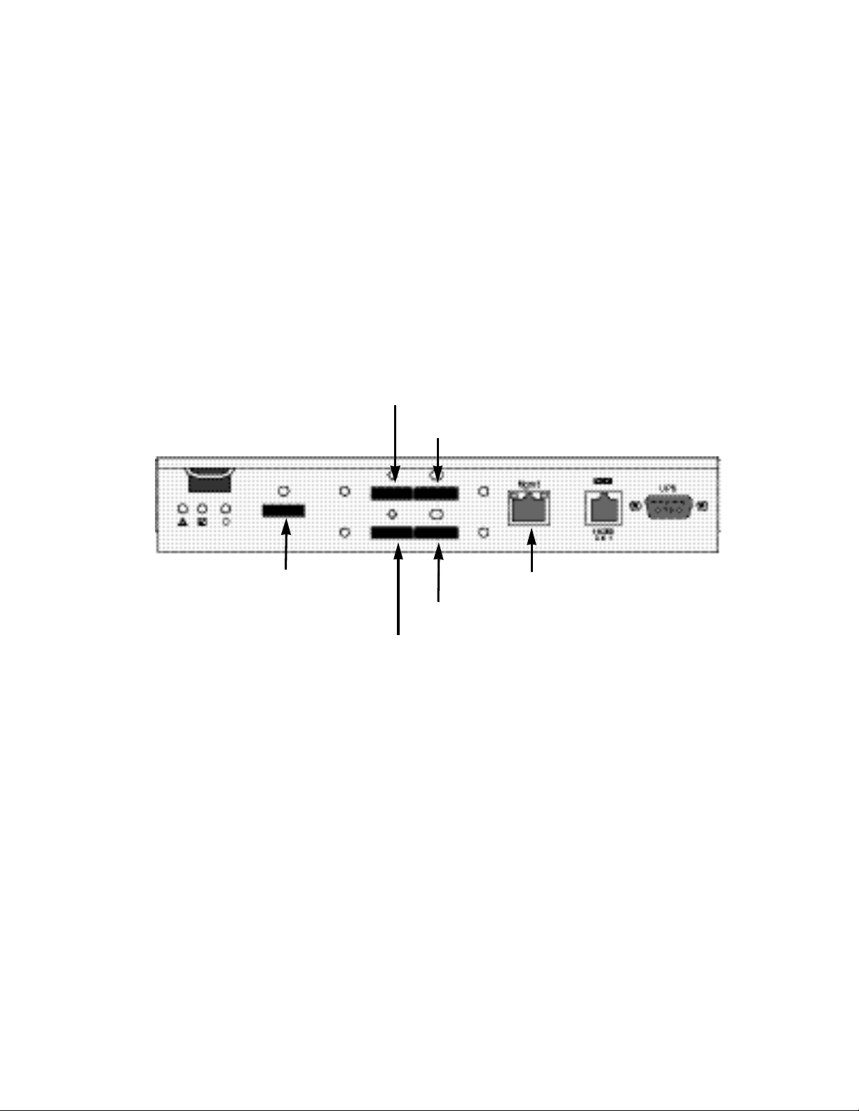
Making Management and Data Connections
Fibre Channel data port 1
SAS expansion
port (to JBOD)
Management port
Fibre Channel data port 2
For Serial Attached SCSI setup skip to the next section.
Fibre Channel Host
Astra ES models can have one or two RAID controllers. Each controller has an Ethernet (RJ45) Management
Port connector that enables you to monitor the Astra ES over your network using the Astra ES Management GUI
Software. Astra ES supports HTTP(S) and Telnet protocols.
The Astra ES RAID controller has two 4-Gb Fibre Channel (FC) connections for the data ports.
You can configure your Astra ES for:
• Storage Area Network (SAN)
• Direct Attached Storage (DAS)
• JBOD Expansion using a SAS data connection
Configuring a Storage Area Network
A storage area network (SAN) requires:
• A Fibre Channel switch
• A Fibre Channel HBA card in each Host PC or Server
• A network switch
• A network interface card (NIC) in each Host PC or Server
To establish the data path:
On the Astra ES controller, connect one of the Fibre Channel data ports to your Fibre Channel switch.
To establish the management path:
1. On the Astra ES controller, connect the Management Port to your network switch.
2. Connect each Host PC’s or Server’s standard NIC to your network switch.
Configuring Direct Attached Storage
Direct attached storage (DAS) requires:
• Two Fibre Channel HBA cards in the Host PC or Server
• A network switch
• A network interface card (NIC) in the Host PC or Server
Figure 4: Fibre Channel controller data and management connectors
To establish the data path:
16 EXCEL MERIDIAN DATA
Page 17

On the Astra ES controller, connect one of the Fibre Channel data ports to your Fibre Channel switch.
To establish the management path:
1. On the Astra ES controller, connect the Management Port to your network switch.
2. Connect the Host PC’s or Server’s standard NIC to your network switch.
Configuring JBOD expansion:
To expand the number of disk drives:
1. On the RAID controller, connect the SAS connector (a subtractive-routed port) to CN1 (a table-routed port)
on the I/O module of the first JBOD unit.
2. Connect CN3 (a subtractive-routed port) on the first JBOD unit to CN1 on one of the I/O modules of the next
JBOD unit.
3. Connect the remaining JBOD units in the same manner.
You can expand a SAN system with no single point of failure. Such an arrangement requires:
• Two Fibre Channel switches
• Two Fibre Channel HBA cards in each Host PC or Server
• A network switch (not shown)
• A network interface card (NIC) in each Host PC or Server
This completes management and data connections for Astra ES Fibre Channel Host.
SECURSTOR ASTRA ES 17
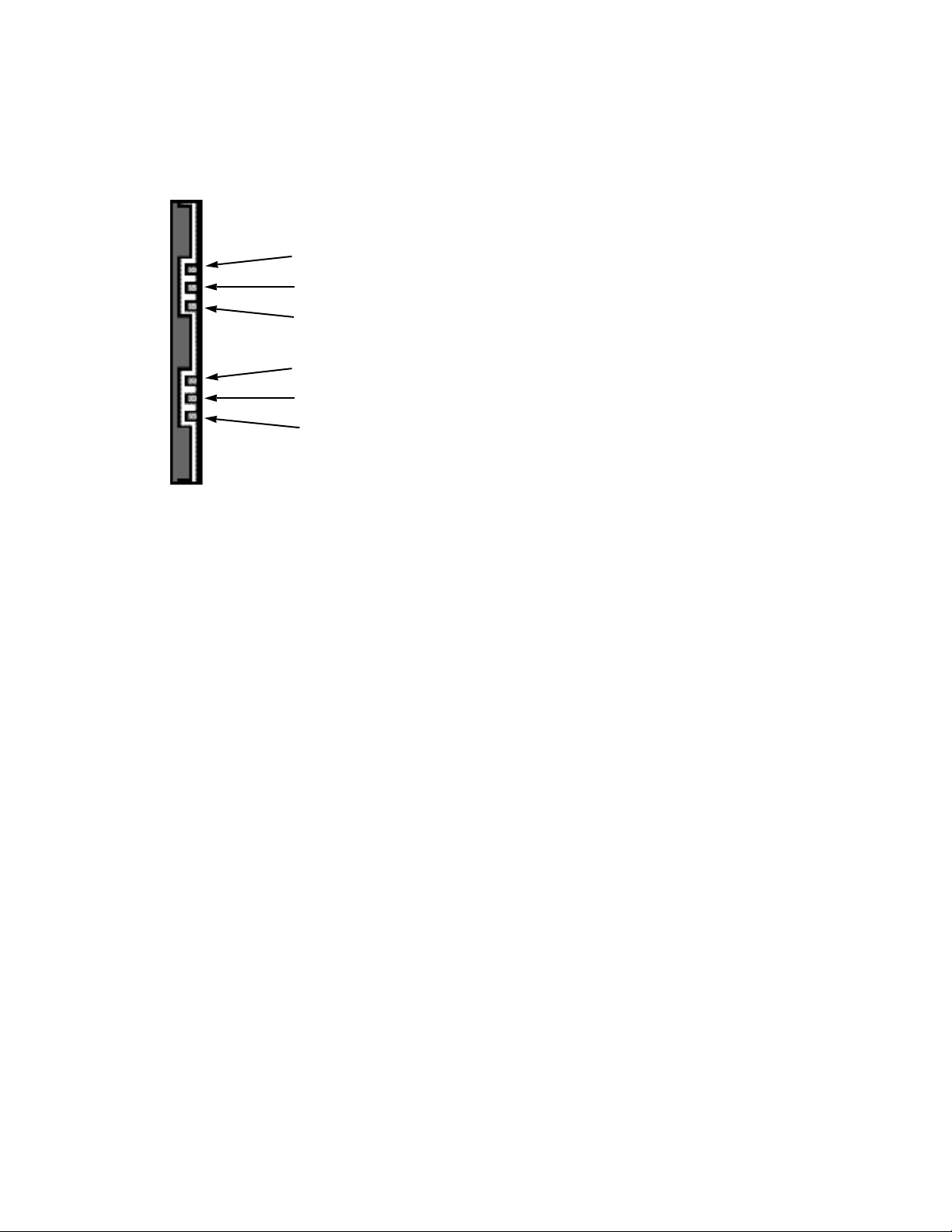
Page 18
SAS data port (optional)
SAS data/cascade port (optional)
SAS data/cascade port
SAS data port
SAS expansion
port (to JBOD)
Management port
Serial Attached SCSI Host
Astra ES models can have one or two RAID controllers. Each controller has an Ethernet (RJ45) Management
Port connector that enables you to monitor the Astra ES over your network using the Astra ES Management GUI
Software. Astra ES supports HTTP(S) and Telnet protocols.
The standard Astra ES SAS Host controller has three SAS ports:
• Data port – Connects to the Host PC or Server
• Data/Cascade port – Connects to the data port of a second Astra ES SAS controller or to the Host PC or
Server
• SAS Expansion port – Connects to a Astra ES JBOD expansion subsystem
You can configure your Astra ES for:
• Direct Attached Storage (DAS)
• Cascaded Storage (Multiple Astra ES subsystems)
• JBOD Expansion using a SAS data connection
Configuring Direct Attached Storage
Direct attached storage (DAS) requires:
• Two SAS HBA cards in the Host PC or Server
• A network switch
• A network interface card (NIC) in the Host PC or Server
To establish the data path:
On the Astra ES controller, connect a SAS data port or a SAS data/cascade port to one of your SAS HBA cards.
To establish the management path:
1. On the Astra ES controller, connect the Management Port on each Controller to your network switch.
2. Connect the Host PC’s or Server’s standard NIC to your network switch.
18 EXCEL MERIDIAN DATA
Figure 5: SAS controller data and management
Page 19

Configuring Cascaded Storage
Cascaded storage requires:
• One SAS HBA card in the Host PC or Server
• A network switch
• A network interface card (NIC) in the Host PC or Server
To establish the data path:
1. On the Astra ES controller, connect a SAS data port or a SAS data/cascade port to your SAS HBA card.
2. Connect the data/cascade port (a subtractive-routed port) of the first Astra ES RAID header to the data port
(a table-routed port) on the second Astra ES RAID header.
3. Connect the remaining Astra ES RAID headers in the same manner.
You can cascade up to eight Astra ES subsystems.
To establish the management path:
1. On the Astra ES controller, connect the Management Port on each Controller to your network switch.
2. Connect the Host PC’s or Server’s standard NIC to your network switch.
Configuring JBOD expansion:
To expand the number of disk drives:
1. On the Astra ES RAID controller, connect the SAS expansion port (a subtractive-routed port) to the CN1 (a
table-routed port) on one of the I/O modules of the first JBOD unit.
2. Connect CN3 (a subtractive-routed port) on the first JBOD unit to CN1 on one of the I/O modules of the next
JBOD unit.
3. Connect the remaining JBOD units in the same manner.
You can expand a SAN system with no single point of failure. Such an arrangement requires:
• Two SAS HBA cards in each Host PC or Server
• A network switch (not shown)
• A network interface card (NIC) in each Host PC or Server
• One to four Astra ES JBOD subsystems
This completes Network and Data connections for Astra ES SAS Host.
SECURSTOR ASTRA ES 19
Page 20
Power
Controller-2 Activ ity
FRU Status
Logical Driv e Status
Controller-1 Activ ity
Controller Heartbeat
Connecting the Power
Plug the power cords and switch on both power supplies on. When the power is switched on, the LEDs on the
front of the Astra ES will light up.
Figure 6: Astra ES front panel LED display
When boot-up is finished and the Astra ES is functioning normally:
• Controller LED blinks green once per second for five seconds, goes dark for ten seconds, then blinks green
once per second for five seconds again.
• Power, FRU and Logical Drive LEDs display green continuously.
• Controller LEDs flash green if there is activity on that controller.
There are two LEDs on each disk drive carrier. They report the presence of power and a disk drive, and the
current condition of the drive.
After a few moments the Power/Activity LED should display Green. If there is no disk drive in the carrier, the
Power/Activity LED will remain dark.
The Power/Activity LED flashes during drive activity.
The Disk Status LED displays Green when a drive is present and configured.
20 EXCEL MERIDIAN DATA
Page 21

Chapter 3: Management with Astra GUI
• Logging into Astra GUI
• Selecting a language
• Perusing the interface
• Logging out of Astra GUI
• Working with the Storage Network
• Working with Subsystems
• Managing the User Database
• Managing the Ethernet Network
interfaces
• Managing the Fibre Channel
interfaces
• Managing the SAS interfaces
• Managing the Storage Services
• Managing the Software Services
• Exporting the User Database
• Importing a User Database
• Updating the Firmware
• Restoring the Factory Defaults
• Clearing statistics
• Shutting down and Restarting the
subsystem
• Managing controllers
• Managing enclosures
• Managing physical drives
• Managing disk arrays
• Managing logical drives
• Managing spare disk drives
• Working with the logical drive
summary
Note
This chapter covers the following topics:
Logging into Astra GUI
In order to log into Astra GUI, you must first know the IP address of the SecurStor Astra ES on your network. By
default, the unit will obtain an IP address from your DHCP server. Use your normal DHCP scope browse tools to
locate the Astra ES IP. The full MAC address for each Ethernet Network Interface is labeled next to the RJ-45
Ethernet Port on the rear of the unit.
To log into Astra GUI:
1. Launch your Browser.
2. In the Browser address field, type in the IP address of the Astra ES Management port.
Note that the IIP address shown below is only an example. The IP address you type into your browser will
be different.
Regular Connection
• Astra ES uses an HTTP connection ........................................ .http://
• Enter the Astra ES Management Port IP address....... 192.168.10.85
Together, your entry looks like this:
http://192.168.10.85
Secure Connection
• Astra ES uses a secure HTTP connection ............................. .https://
• Enter the Astra ES Management Port IP address....... 192.168.10.85
Together, your entry looks like this:
https://192.168.10.85
SECURSTOR ASTRA ES 21
Page 22

Whether you select a regular or a secure connection, your login
to Astra GUI and your user password are always secure.
3. When the log-in screen (Figure 1) appears:
• Type administrator in the User Name field.
• Type admin in the Password field.
• Click the Login button.
The User Name and Password are case sensitive.
4. Click the Login button.
Selecting a Language
Astra GUI displays in English, German, French, Italian, Japanese, Chinese Traditional, Chinese Simple, and
Korean.
1. Click Language the Astra GUI Header.
The language list appears in the Header.
2. Click the language you prefer.
The Astra GUI user interface displays in the selected language.
Figure 7: Selecting the language from the header bar
Perusing the Interface
Astra GUI is browser-based RAID management software with a graphic user interface.
There are four major parts to the graphic user interface:
• Header Bar
• Left Navigation Tree
• Management View
• Event Frame
Using the Header
The Header contains the following items:
• Language – To change languages.
• View – To view the Event Frame in-line at the bottom of each page.
• Storage Network – To view all of the Astra subsystem enclosures currently accessible the network.
• Contact Us – Click on Contact Us for a list of contact information, including Technical Support.
• Logout – To logout of Astra GUI.
• Help – Click on Help in the Header to access the main online help menu.
• About – Click on About in the Header to display the Astra ES software version and build date.
22 EXCEL MERIDIAN DATA
Page 23

Using Tree View
Tree View enables you to navigate around all components of the Subsystem, including Fibre Channel or SAS
management, network and service management, RAID controller, enclosure, physical drives, disk arrays, logical
drives, and spare drives. The figure below shows the components of Tree View.
The Administrative Tools section is different for the Super User than for other users. The remainder of the Tree is
the same for all users.
Management View displays information according to the item you select in Tree View.
Using Management View
Management View provides the actual user interface with the Astra ES, including creation, maintenance,
deletion, and monitoring of disk arrays and logical drives.
Function Tabs control specific actions and processes. This window changes depending on which item you select
in Tree View and which tab you select in Management View itself.
Click the Help button in Management View to access online help for the function that is currently displayed.
Viewing the Event Frame
To view the Event Frame:
1. Click on View in the Header.
2. Click the Show Event Frame popup option.
The Astra ES user interface will display the Event Frame below Management View.
3. Click View again to hide the Event Frame.
In the event frame, events are listed and sorted by:
• Item Number – A consecutive decimal number assigned to a specific event
• Device – Battery, controller, logical drive, physical drive, port, etc.
• Event ID – The hexadecimal number that identifies the specific type of event
• Severity – Information, Warning, Minor, Major, Critical, and Fatal. The severity level is user-specified.
• Time – Time and date of the occurrence
• Description – A brief description of the event
Sorting Events
You can sort the events by Item Number, Device, Event ID, Severity, Time and Date, or Description.
Click on the link at the top of the column by which you want to sort the events. After you click on the item, a
triangle icon appears.
• If the triangle points upward, the column is sorted low-to-high or old-to-new.
• If the triangle points downward, the column is sorted high-to-low or new-to-old.
Click the link a second time to change to flip the triangle and reverse the sort sequence.
Logging out of Astra GUI
There are two ways to log out of Astra Management GUI:
• Close your browser window
• Click Logout the Astra GUI banner
SECURSTOR ASTRA ES 23
Page 24

Figure 8: Clicking logout in the header bar
Clicking Logout brings you back to the Login Screen. After logging out, you must enter your user name and
password in order to log in again.
Working with the Storage Network
When you log into Astra Management GUI, you access a specific Astra ES subsystem.
The Storage Network feature enables you to access all of the Astra subsytems with a Management Port
connection to your network.
Each Astra ES subsystem is identified by its Management Port IP address.
Storage Network functions include:
• Viewing other subsystems
• Updating the list of subsystems
• Logging into a subsystem
• Hiding the other subsystems
Viewing Other Subsystems
To view the other Astra subsystems the Storage Network:
1. Click on Storage Network in the Header.
2. Click the Show Network Subsystems popup option.
The list will show all subsystems the network at the time the GUI was launched.
Updating the List of Subsystems
To update the list of the Astra subsytems the Storage Network:
Click the Discover button at the bottom of the subsystem list.
Logging into a Subsystem
To log into any of the displayed Astra subsystems:
1. In Tree View, click the Subsystem icon of the subsystem you want to see.
If your user name and password do not match the subsystem you are logging into, the log in screen will
appear.
2. Log into the new subsystem, as needed.
Hiding the Other Subsystems
To hide the other Astra subsystems the Storage Network:
1. Click on Storage Network in the Header.
2. Click the Hide Network Subsystems popup option.
Working with Subsystems
An Astra subsystem is identified by its Management Port IP address. Subsystem functions include:
• Viewing Subsystem Information
• Setting an Alias
• Setting Redundancy options
• Setting the Date and Time
24 EXCEL MERIDIAN DATA
Page 25

• Viewing and Clearing event logs
• Viewing current Background activities
• Running Media Patrol
• Running PDM
• Viewing, Deleting and Scheduling activities
• Viewing, Setting, Renewing and Releasing the Lock status
Viewing Subsystem Information
To view information about a subsystem, click the Subsystem icon in Tree View. Management View displays
the subsystem information.
Setting an Alias for the Subsystem
An alias is optional. To set an alias for this subsystem:
1. In Tree View, click the Subsystem icon.
2. In Management View, click the Settings tab.
2. Enter a name into the Alias field.
2. Maximum of 48 characters. Use letters, numbers, space between words, and underscore.
4. Click the Submit button.
Setting Redundancy for the Subsystem
To set redundancy for this subsystem:
1. In Tree View, click the Subsystem icon.
2. In Management View, click the Settings tab.
3. In the Redundancy Type dropdown menu, select:
• Active-Active – Both RAID controllers are active and can share the load
• Active-Standby – One RAID controller is in standby mode and goes active if the other fails
4. Click the Submit button.
If you change Redundancy Type, be sure both controllers are properly installed in the subsystem before you
restart.
If your subsystem has dual controllers and they are set to Active-Active, you can use the LUN Affinity feature.
Setting Subsystem Date and Time
To set a Date and Time for this subsystem:
1. In Tree View, click the Subsystem icon.
2. In Management View, click the Settings tab dropdown menu and select Date and Time Settings.
3. Under Subsystem Date, select the Month and Day from the dropdown menus.
4. Type the current year into the Year field.
5. Under Subsystem Time, select the Hour, Minutes and Seconds from the dropdown menus.
6. Click the Submit button.
Viewing the Runtime Event Log
Runtime Events lists information about the 1023 most recent runtime events recorded since the system was
started. To view runtime events:
1. In Tree View, click the Subsystem icon.
2. In Management View, click the Events tab dropdown menu and select Runtime Events.
Events are displayed by:
• Item Number – A consecutive decimal number assigned to a specific event
• Device – Battery, controller, logical drive, physical drive, port, etc.
• Event ID – The hexadecimal number that identifies the specific type of event
SECURSTOR ASTRA ES 25
Page 26

• Severity – Information, Warning, Minor, Major, Critical, and Fatal. The severity level is user-specified.
• Time – Time and date of the occurrence
• Description – A brief description of the event
3. Click on the link at the top of the column by which you want to sort the events. After you click on the item, a
triangle icon appears.
• If the triangle points upward, the column is sorted low-to-high or old-to-new.
• If the triangle points downward, the column is sorted high-to-low or new-to-old.
Click the link a second time to change to flip the triangle and reverse the sort sequence.
Saving the Runtime Event Log
To save the runtime event log as a text file:
1. In Tree View, click the Subsystem icon.
2. In Management View, click the Events tab dropdown menu and select Runtime Events.
3. Click the Save Event Log button.
4. In the File Download dialog box, click the Save button.
5. In the Save dialog box, name the file, navigate to the folder where you want to save the log file, and click the
Save button.
Clearing the Runtime Event Log
To clear the runtime event log:
1. In Tree View, click the Subsystem icon.
2. In Management View, click the Events tab dropdown menu and select Runtime Events.
3. Click the Clear Event Log button.
4. In the Confirmation dialog box, type confirm and click the OK button.
Viewing NVRAM Events
NVRAM Events lists information about the 63 most recent important events. NVRAM events are stored in nonvolatile memory. To view runtime events:
1. In Tree View, click the Subsystem icon.
2. In Management View, click the Events tab dropdown menu and select System Events in NVRAM.
Events are displayed by:
• Item Number – A consecutive decimal number assigned to a specific event
• Device – Battery, controller, logical drive, physical drive, port, etc.
• Event ID – The hexadecimal number that identifies the specific type of event
• Severity – Information, Warning, Minor, Major, Critical, and Fatal. The severity level is user-specified.
• Time – Time and date of the occurrence
• Description – A brief description of the event
3. Click on the link at the top of the column by which you want to sort the events. After you click on the item, a
triangle icon appears.
• If the triangle points upward, the column is sorted low-to-high or old-to-new.
• If the triangle points downward, the column is sorted high-to-low or new-to-old.
Click the link a second time to change to flip the triangle and reverse the sort sequence.
Saving NVRAM Events
To save the NVRAM event log as a text file:
1. In Tree View, click the Subsystem icon.
2. In Management View, click the Events tab dropdown menu and select System Events in NVRAM.
3. Click the Save Event Log button.
4. In the File Download dialog box, click the Save button.
26 EXCEL MERIDIAN DATA
Page 27

5. In the Save dialog box, name the file, navigate to the folder where you want to save the log file, and click the
Save button.
Clearing NVRAM Events
To clear the NVRAM event log:
1. In Tree View, click the Subsystem icon.
2. In Management View, click the Events tab dropdown menu and select System Events in NVRAM.
3. Click the Clear Event Log button.
4. In the Confirmation dialog box, type confirm and click the OK button.
Viewing Current Background Activities
To view the current background activities:
1. In Tree View, click the Subsystem icon.
2. In Management View, click the Background Activities tab.
A list of current background activities appears, including:
• Rebuild
• PDM – Predictive Data Migration
• Synchronization
• Redundancy Check
• Migration
• Transition
• Initialization
• Media Patrol
Making Background Activity Settings
To make settings for background activities:
1. In Tree View, click the Subsystem icon.
2. In Management View, click the Background Activities tab and select Settings from the dropdown menu.
3. Click the dropdown menu to choose a priority of Low, Medium, and High for the following functions:
• Rebuild – Rebuilds the data from a failed drive in a disk array
• Synchronization – Checks the data integrity on disk arrays
• Initialization – Sets all data bits in the logical drive to zero
• Redundancy Check – Checks, reports and can correct data inconsistencies in logical drives
• Migration – Change RAID level or add physical dries to disk arrays
• PDM – Looks for bad blocks the physical drives of disk arrays
• Transition – Returns a revertible spare drive to spare status
The rates are defined as follows:
• Low – Fewer resources to activity, more to data read/write.
• Medium – Balance of resources to activity and data read/write.
• High – More resources to activity, fewer to data read/write.
4. Highlight the following PDM trigger settings and type a value into the corresponding field:
• Reassigned Block Threshold – 1 to 512 blocks
• Error Block Threshold – 1 to 1024 blocks
5. Check to enable or uncheck to disable the following functions:
• Media Patrol – Checks the magnetic media on physical drives
• Auto Rebuild – If there is a spare drive of adequate capacity, a critical disk array will begin to rebuild
automatically. If not spare drive is available, the disk array will begin to rebuild as soon as you replace
the failed physical drive with an unconfigured physical drive of equal or greater size.
6. Click the Submit button to save your settings.
SECURSTOR ASTRA ES 27
Page 28

Running Background Activities
To run a background activity from the Background Activities tab:
1. In Tree View, click the Subsystem icon.
2. In Management View, click the Background Activities tab and select one of the following from the dropdown
menu.
• Media Patrol
• Rebuild
• PDM
• Transition
• Initialization
• Redundancy Check
3. In the next screen, make the choices as requested.
4. Click the Start button.
Running Media Patrol
Media Patrol checks the magnetic media on physical drives. When it finds the specified number of bad blocks, it
will trigger PDM.
You can also schedule Media Patrol to run automatically.
To run Media Patrol:
1. In Tree View, click the Subsystem icon.
2. From the dropdown menu on the Background Activities tab, select Start Media Patrol.
3. In the next screen, click the Start button.
Running PDM
Predictive Data Migration (PDM) migrates data from the suspect physical drive to a spare disk drive, similar to
Rebuilding. But unlike Rebuilding, PDM acts before the disk drive fails and your Logical Drive goes Critical.
To run PDM:
1. In Tree View, click the Subsystem icon.
2. In Management View, click the Background Activities tab and select Start Media Patrol from the dropdown
menu.
3. In the next screen, select the Source and Target physical drives.
The suspect physical drive is the source. The replacement physical drive is the target.
4. Click the Start button.
Viewing Scheduled Activities
To view scheduled activities for this subsystem:
1. Click the Subsystem icon Tree View.
2. Click the Scheduler tab in Management View.
Scheduling an Activity
To set a scheduled activity for this subsystem:
1. Click the Subsystem icon Tree View.
2. From the dropdown menu on the Scheduler tab, choose an item:
• Media Patrol
• Redundancy Check
• Battery Reconditioning
• Spare Drive Check
28 EXCEL MERIDIAN DATA
Page 29
3. In the Scheduler dialog box, check the Enable This Schedule box.
Note
You can schedule only ONE Redundancy Check for each logical
drive.
4. Select a start time (24-hour clock).
5. Select a Recurrence Pattern.
• Daily – Enter the number of days between events.
• Weekly – Enter the number of weeks between events and select which days of the week.
• Monthly – Select a calendar day of the month (1 – 31).
If you select a higher number than there are days in the current month, the actual start date will occur at the
beginning of the following month.
Or, select a day of the week and select the first, second, third, fourth, or last occurrence of that day in the
month.
Then, select the months in which you want the activity to occur.
6. Select a Range of Occurrence.
• Start-from date. The default is today's date.
• End-on date.
Select No End Date (perpetual).
Or, select a number of occurrences for this activity.
Or, select a specific end date. The default is today's date.
7. For Redundancy Check only:
• Choose the Auto Fix option. This feature attempts to repair the problem when it finds an error.
• Choose the Pause on Error option. This feature stops the process when it finds an error
• Check the boxes beside the logical drives (all except RAID 0) to which this activity will apply.
Each logical drive can have only one scheduled Redundancy Check.
8. Click the Submit button.
Deleting a Scheduled Activity
To delete a scheduled activity for this subsystem:
1. Click the Subsystem icon Tree View.
2. From the dropdown menu on the Scheduler tab, choose Delete Schedules.
3. Check the box to the left of the schedule you want to delete.
4. Click the Submit button.
Viewing Lock Status
The lock prevents other sessions (including by the same user) from making a configuration change to the
controller until the lock expires or a forced unlock is done.
To view the lock status for this subsystem:
1. Click the Subsystem icon Tree View.
2. Click the Lock tab in Management View.
The following information is displayed:
• Lock Status – The User who set (owns) the current lock.
• Expiration Time – Amount of time left until the lock automatically releases.
• Expire At Time – The date and time when the lock will automatically release.
Setting the Lock
SECURSTOR ASTRA ES 29
Page 30

The lock prevents other sessions (including by the same user) from making a configuration change to the
controller until the lock expires or a forced unlock is done.
You can set the lock to last from one minute to one day. To set the lock for this subsystem:
1. Click the Subsystem icon Tree View.
2. Click the Lock tab in Management View.
3. Click the Lock option.
4. Enter a time interval between 1 and 1440 minutes (one day) that you want the lock to stay active.
5. Click the Submit button.
Renewing the Lock
The lock prevents other sessions (including by the same user) from making a configuration change to the
controller until the lock expires or a forced unlock is done.
Renewing the lock extends the period of time the controller remains locked. To renew an existing lock for this
subsystem:
1. Click the Subsystem icon Tree View.
2. Click the Lock tab in Management View.
3. Click the Renew option.
4. Enter a time interval between 1 and 1440 minutes (one day) that you want the lock to stay active.
The renew time replaces the previous Expiration Time.
5. Click the Submit button.
Releasing the Lock
The lock prevents other sessions (including by the same user) from making a configuration change to the
controller until the lock expires or a forced unlock is done.
When the user who locked the controller logs out, the lock is automatically released. You can also release the
lock before the scheduled time.
To release the lock for this subsystem:
1. Click the Subsystem icon Tree View.
2. Click the Lock tab in Management View.
If you are the User who set the lock, click the Unlock option.
If another User set the lock and you are a Super User, click the Unlock option and check the Force Unlock
box.
3. Click the Submit button.
Managing Users
User Management includes all functions dealing with user accounts. Functions include:
• Viewing User Information
• Managing User Settings
• Changing User Passwords
• Creating and Deleting Users
• Viewing and Managing other User Sessions
Viewing User Information
The view a list of users, their status, access privileges, display name, and email address:
1. Click the Subsystem icon in Tree View.
2. Click the Administrative Tools icon.
3. Click the User Management icon.
The Information tab appears in Management View.
30 EXCEL MERIDIAN DATA
Page 31

Making User Settings
To change settings of other users:
1. Log into Astra GUI as the Administrator or a Super User.
2. Click the Subsystem icon in Tree View.
3. Click the Administrative Tools icon.
4. Click the User Management icon.
5. On the Information tab, click the link of the user whose settings you want to change.
The Settings screen for the selected user displays.
6. Make the following settings as needed.
• Check the Enable box to enable this user.
• Uncheck the box to disable this user.
• Enter or change the display name.
• Enter or change the email address.
• From the Privilege dropdown menu, choose a new level.
7. Click the Submit button.
The Administrator or Super User can change another user’s password.
Modifying Your Own User Settings
To change your own user settings:
1. Log into Astra GUI under your own user name.
2. Click the Subsystem icon in Tree View.
3. Click the Administrative Tools icon.
4. Click the User Management icon.
5. Click the Settings tab in Management View.
6. Enter or change the display name or mail address.
7. Click the Submit button.
Setting-up User Event Subscriptions
An event subscription enables a user to receive email messages about events taking place in the Astra ES
subsystem. To make or change user event subscriptions:
1. Click the Subsystem icon in Tree View.
2. Click the Administrative Tools icon.
3. Click the User Management icon.
4. Click the Event Subscription tab in Management View.
5. Check the box to enable event notification.
6. Under the subheadings, select the lowest level of Severity to be reported for each event. The selected level
plus all higher levels of Severity will be reported.
• Information – Information only, no action is required
• Warning – User can decide whether or not action is required
• Minor – Action is needed but the condition is not a serious at this time
• Major – Action is needed now
• Critical – Action is needed now and the implications of the condition are serious
• Fatal – Non-Recoverable error or failure has occurred
• None – Deactivates this event for notification purposes
7. Click the Submit button.
The user’s account must have an email address. To send a test message to the email address in the listed under
General Info, click the Test Email button.
SECURSTOR ASTRA ES 31
Page 32

Changing Another User’s Password
To change a user’s password:
1. Log into Astra GUI as the Administrator or a Super User.
2. Click the Subsystem icon in Tree View.
3. Click the Administrative Tools icon.
4. Click the User Management icon.
5. In the list of users, click the link of the user whose settings you want to change.
The Settings screen for the selected user displays.
6. Click the Password tab in Management View.
7. Enter the new password in the New Password field.
8. Enter the new password in the Retype Password field.
9. Click the Submit button.
Changing Your Own Password
To set or change your own password:
1. Log into Astra GUI under your own user name.
2. Click the Subsystem icon in Tree View.
3. Click the Administrative Tools icon.
4. Click the User Management icon.
5. Click the Password tab in Management View.
6. Enter the current password in the Old Password field.
If you do not have a password, leave this field blank.
7. Enter the new password in the New Password field.
8. Enter the new password in the Retype Password field.
9. Click the Submit button.
Creating a User
To create a user:
1. Log into Astra GUI as the Administrator or a Super User.
2. Click the Subsystem icon in Tree View.
3. Click the Administrative Tools icon.
4. Click the User Management icon.
5. Click the Create tab in Management View.
6. Enter a user name in the User Name field.
7. Enter a password for this user in the New Password and Retype Password fields.
A password is optional. If you do not specify a password, log into Astra GUI with the User Name and leave
the password field blank.
8. Enter a display name in the Display Name field.
A display name is optional.
9. Enter the user's email address in the Email Address field.
An email address is required in order to receive email event notification.
10. Select a privilege level from the Privilege dropdown menu.
For definitions of each privilege level, see the List of User Privileges below.
11. Check the Enabled box to enable this user on this subsystem.
12. Click the Submit button.
List of User Privileges
• View – Allows the user to see all status and settings but not to make any changes
32 EXCEL MERIDIAN DATA
Page 33

• Maintenance – Allows the user to perform maintenance tasks including Rebuilding, PDM, Media Patrol, and
Redundancy Check
• Power – Allows the user to create (but not delete) disk arrays and logical drives, change RAID levels,
change stripe size; change settings of components such as disk arrays, logical drives, physical drives, and
the controller.
• Super – Allows the user full access to all functions including create and delete users and changing the
settings of other users, and delete disk arrays and logical drives. The default ―administrator‖ account is a
Super User.
Deleting a User
There will always be at least one Super User account. You cannot delete the user account you used to log in.
To delete a user:
1. Log into Astra GUI as the Administrator or a Super User.
2. Click the Subsystem icon in Tree View.
3. Click the Administrative Tools icon.
4. Click the User Management icon.
5. Click the Delete tab in Management View.
6. Check the box to the left of the user you want to delete.
7. Click the Submit button.
8. Click OK in the confirmation box.
Viewing User Sessions
To view the current sessions:
1. Click the Subsystem icon in Tree View.
2. Click the Administrative Tools icon.
3. Click the User Management icon.
4. Click the Sessions tab in Management View.
Logging out Other Users
To logout other users:
1. Log into Astra GUI as the Administrator or a Super User.
2. Click the Subsystem icon in Tree View.
3. Click the Administrative Tools icon.
4. Click the User Management icon.
5. Click the Sessions tab in Management View.
6. Check the box to the left of the user you want to log out.
7. Click the Logout button.
8. Click OK in the confirmation box.
Managing the Network Connection
The network connection deals with network connections to the Astra ES’s Management Ports. Functions include:
• Modifying Subsystem Management Port Settings
• Modifying Controller Management Port Settings
Modifying Subsystem Management Port Settings
The Astra ES subsystem has a virtual management port. When you log into the Astra ES over your network, you
use the virtual management port. This arrangement enables you to log into a Astra ES with two controllers using
one IP address.
SECURSTOR ASTRA ES 33
Page 34

To make changes to the Subsystem Management Port settings:
1. Click the Subsystem icon in Tree View.
2. Click the Administrative Tools icon.
3. Click the Network Management icon.
4. Click the Port Configuration link in Management View.
5. To enable DHCP, check the DHCP box.
When DHCP is NOT enabled, enter:
• Primary IP address
• Primary subnet mask
• Default gateway IP address
• Enter a primary DNS server IP address.
6. Click the Submit button.
Modifying Controller Management Port Settings
The controller has an IP addresses for access when the controller goes into maintenance mode. Maintenance
mode is only for remedial action in the event of a problem with the controller.
To make changes to the Controller Management Port settings:
1. Click the Subsystem icon in Tree View.
2. Click the Administrative Tools icon.
3. Click the Network Management icon.
4. Click the Maintenance Mode tab in Management View.
5. Click the Port Configuration link for Controller 1 or 2.
6. To enable DHCP, check the DHCP box.
When DHCP is NOT enabled, enter:
• Primary IP address
• Primary subnet mask
• Default gateway IP address
• Enter a primary DNS server IP address.
7. Click the Submit button.
8. Click the Maintenance Mode tab again.
9. Click the Port Configuration link for the other controller.
10. To enable DHCP, check the DHCP box.
When DHCP is NOT enabled, enter:
• Primary IP address
• Primary subnet mask
• Default gateway IP address
• Enter a primary DNS server IP address.
11. Click the Submit button.
Managing Fibre Channel Connections
This feature pertains to Astra ES Fibre Channel models. Functions include:
• Viewing Fibre Channel Node Information
• Viewing and Modifying Fibre Channel Port Settings
• Viewing Fibre Channel logged-in devices and initiators
Viewing Fibre Channel Node Information
To view Fibre Channel node information:
1. Click the Subsystem icon in Tree View.
34 EXCEL MERIDIAN DATA
Page 35

2. Click the Administrative Tools icon.
3. Click the Fibre Channel Management icon.
4. Click the Node tab in Management View.
The current node (data port) settings the Controller are shown, including:
• WWNN – World Wide Node Name
• Supported Features – Class of service
• Maximum Frame Size – 2048 bits
• Supported Speeds – 4 Gb/s, 2Gb/s, or 1 Gb/s
Viewing Fibre Channel Port Settings
To view the current Fibre Channel port settings:
1. Click the Subsystem icon in Tree View.
2. Click the Administrative Tools icon.
3. Click the Fibre Channel Management icon.
4. Click the Port tab in Management View
The current data port settings the Controller are shown, including:
• State – Online, Offline, Unknown
• Port Identifier – A hexadecimal name for this port
• Topology Attached – See the table on Fibre Channel Attached T
• Fabric WWNN – World Wide Node Name (appears when connected to a switch)
• Fabric WWPN – World Wide Port Name (appears when connected to a switch)
• Current Speed – 4 Gb/s, 2 Gb/s, or 1 Gb/s
• Link Type – Long-wave laser, short-wave laser or electrical
• Symbolic Name – A text name for this port
• Link Speed* – 4 Gb/s, 2 Gb/s, 1 Gb/s, or Auto
• Topology* – NL-Port, N-Port, or Auto
• Hard ALPA* – Address can be 0 to 254. 255 means this feature is disabled
• Alias WWPN
* Denotes items that you can change under Port Settings, below.
Modifying Fibre Channel Port Settings
To modify Fibre Channel port settings:
1. Click the Subsystem icon in Tree View.
2. Click the Administrative Tools icon.
3. Click the Fibre Channel Management icon.
4. Click the Port tab in Management View
5. Click the Port1 or Port2 link in Management View.
6. Make the settings appropriate to your system. See Port Setting Information.
• Configured Link Speed – 4 Gb/s, 2 Gb/s, 1 Gb/s or Auto (self-setting)
• Configured Topology – N-Port (Point-to-Point), NL Port (Arbitrated Loop) or Auto (self-setting)
• Hard ALPA – Address can be 0 to 254. 255 means this feature is disabled. An ALPA identifies a port in
an arbitrated loop.
7. Click the Submit button to save your settings.
SECURSTOR ASTRA ES 35
Page 36

Port Setting Information
Fibre Channel Attached Topology
Configured Topology
Connection Type
N-Port
NL-Port
Switch
Fabric Direct
Public Loop
Direct
Point to Point
Private Loop
Note
In some cases, HBA settings to N-Port only work if connected to
the switch. Refer to your HBA manual for more information.
The table below shows the type of attached topology you will achieve based on your connection type and
the configured topology you select.
Example 1: If you connect the Astra ES to a Fibre Channel switch and select NL-Port topology, you will
create a Public Loop attached topology.
Example 2: If you have a Point to Point attached topology, you made a direct connection (no switch) and
selected N-port topology.
Viewing Fibre Channel Port Statistics
To view statistics for the Fibre Channel ports:
1. Click the Subsystem icon in Tree View.
2. Click the Administrative Tools icon.
3. Click the Fibre Channel Management icon.
4. Click the Statistic tab in Management View.
The statistics for all Fibre Channel ports are shown.
Clearing Statistics
Viewing SFP Information
SFPs (small form-factor pluggable) transceivers connect the ports the Astra ES controllers to the Fibre Channel
fabric.
To view SFP information:
1. Click the Subsystem icon in Tree View.
2. Click the Administrative Tools icon.
3. Click the Fibre Channel Management icon.
4. Click the SFP tab in Management View.
The SFP information for all Fibre Channel ports is shown.
SFP Information
• Connector – Type of connector
• Transceiver – SFP
36 EXCEL MERIDIAN DATA
Page 37

• Transceiver Code – Defines the method to interpret the transceiver type and compatibility options
• Serial Encoding – Serial encoding algorithm
• Bit Rate – In gigabits per second
• Link Length – The maximum link length depending the type of fiber
• Vendor Name – Vendor name of the SFP transceiver
• Vendor OUI – Organizational Unique Identifier, SFP vendor’s IEEE company ID
• Vendor Part Number
• Vendor Revision
• Vendor Serial Number
• Manufacturing Date – Code with 2 digits each for year, month, day, and optional vendor-specific lot number
Viewing Fibre Channel Logged-in Devices
To view a list of the devices currently logged into the Astra ES:
1. Click the Subsystem icon in Tree View.
2. Click the Administrative Tools icon.
3. Click the Fibre Channel Management icon.
4. Click the Logged In Device tab in Management View.
One of the devices in the list will be the port itself. If there is no other device, this notification will appear:
―There is no logged in device.‖ If a Fibre Channel switch is attached, it will also appear in this list.
Viewing Fibre Channel Initiators
You must add an initiator to the Astra ES initiator list in order to use the initiator to create a LUN for your logical
drive.
To view a list of recognized initiators:
1. Click the Subsystem icon in Tree View.
2. Click the Administrative Tools icon.
3. Click the Fibre Channel Management icon.
4. Click the Initiator tab in Management View.
A Fibre Channel switch will also display as an initiator in the list. If your Host PC's Fibre Channel HBA is
connected to the Astra ES directly (not though a Fibre Channel switch), the initiator will NOT display in the
initiator list.
Adding an Initiator
To add an initiator to the Astra ES initiator list:
1. Check the box to the left of the initiator.
2. Click the Add to Initiator List button.
The initiator appears under Storage Services. You can then use the initiator to create a LUN.
Managing SAS Connections
This feature pertains to Astra ES Serial Attached SCSI models. Functions include:
• Viewing SAS Port Information
• Viewing and Managing SAS Ports
• Viewing and Managing SAS Initiators
A SAS Controller can have one or two SAS channels. Each SAS channel has two ports:
• Host In or Data Port (a table-routed port)
• Host In/Out or Data Cascade Port (a subtractive-routed port)
To view information about the SAS ports:
1. Click the Subsystem icon in Tree View.
SECURSTOR ASTRA ES 37
Page 38

2. Click the Administrative Tools icon.
3. Click the SAS Management icon.
The port information appears the screen.
• Channel ID
• Port Type
• Link Status
• Link Speed
• SAS Address
• Cable Signal Strength – Adjustable under Port Settings
Modifying SAS Port Settings
A SAS Controller can have one or two SAS channels. Each SAS channel has two ports:
• Host In or Data Port (a table-routed port)
• Host In/Out or Data Cascade Port (a subtractive-routed port)
To make settings to the SAS ports:
1. Click the Subsystem icon in Tree View.
2. Click the Administrative Tools icon.
3. Click the SAS Management icon.
4. In Management View, click the Port 1 or Port 2 link.
5. From the Cable Signal Strength dropdown menu, choose a value.
The range is 1 to 8. 1 is the default. Signal strength correlates to cable length in meters. Example: If you
have a 2 m SAS cable, set signal strength to 2. If performance is unsatisfactory (view port statistics), try
settings of 1 and 3, then use the best setting for your system.
6. Click the Submit button.
Viewing SAS Port Statistics
The SAS Management Statistics tab displays statistical information about all of the SAS ports on the Astra ES
subsystem.
To view information about the SAS ports:
1. Click the Subsystem icon in Tree View.
2. Click the Administrative Tools icon.
3. Click the SAS Management icon.
4. In Management View, click the Statistic tab.
The statistics for the selected port appear the screen.
Viewing SAS Initiators
You must add an initiator to the Astra ES initiator list in order to use the initiator to create a LUN for your logical
drive.
To view a list of recognized initiators:
1. Click the Subsystem icon in Tree View.
2. Click the Administrative Tools icon.
3. Click the SAS Management icon.
4. In Management View, click the Initiators tab.
A list of all currently logged-in initiators appears the screen.
38 EXCEL MERIDIAN DATA
Page 39

Adding an Initiator
To add an initiator to the Astra ES initiator list:
1. Check the box to the left of the initiator.
2. Click the Add to Initiator List button.
Managing Storage Services
Storage services deal with initiators and LUN mapping for Fibre Channel models and for Serial Attached SCSI
models. LUN masking is the process of applying a LUN Map so that each initiator can only access the LUNs
specified for it.
Features include:
• Adding and Deleting an Initiator
• Viewing LUN Mappings
• Enabling LUN Masking
• Managing LUN Mappings
Adding an Initiator
You must add an initiator to the Astra ES initiator list in order to use the initiator to create a LUN
To add an initiator:
1. Click the Subsystem icon in Tree View.
2. Click the Administrative Tools icon.
3. Click the Storage Services icon.
4. Click the Initiators tab in Management View.
5. From the Initiators tab dropdown menu, select Add Initiator.
6. Enter the initiator’s initiator's name in the Initiator Name field.
• Fibre Channel – A Fibre Channel initiator name is the World Wide Port Name of the device and is
composed of a series of eight, two-digit hexadecimal numbers.
• SAS – A SAS initiator name is the SAS address of the HBA card in the Host PC. Obtain the initiator
name from the initiator utility on your host system.
Obtain the initiator name from the initiator utility on your host system.
Note that the initiator name you input must match exactly in order for the connection to work.
7. Click the Submit button.
Deleting an Initiator
To delete an initiator:
1. Click the Subsystem icon in Tree View.
2. Click the Administrative Tools icon.
3. Click the Storage Services icon.
4. Click the Initiators tab in Management View.
5. From the Initiators tab dropdown menu, select Delete Initiators.
6. Check the box to the left of the initiator you want to delete.
7. Click the Submit button.
Viewing the LUN Map
To view the current LUN Map:
1. Click the Subsystem icon in Tree View.
2. Click the Administrative Tools icon.
3. Click the Storage Services icon.
4. Click the LUN Map tab in Management View.
SECURSTOR ASTRA ES 39
Page 40

Enabling LUN Masking
To enable the LUN Masking:
1. Click the Subsystem icon in Tree View.
2. Click the Administrative Tools icon.
3. Click the Storage Services icon.
4. Click the LUN Map tab in Management View.
5. Click the LUN Masking Enabled box.
6. Click the Submit button.
Adding a LUN Map
To edit the LUN Map:
1. Click the Subsystem icon in Tree View.
2. Click the Administrative Tools icon.
3. Click the Storage Services icon.
4. Click the LUN Map tab in Management View and from the dropdown menu, select Add a LUN Map.
5. Select an initiator from the Initiator dropdown list.
Or enter the initiator’s name in the Initiator Name field.
Note that the initiator name you input must match exactly in order for the connection to work.
6. In the LUN Mapping & Masking list, enter the LUNs for each logical drive.
You must enter different LUN numbers for each logical drive.
7. Click the Submit button.
Editing a LUN Map
To edit the LUN Map:
1. Click the Subsystem icon in Tree View.
2. Click the Administrative Tools icon.
3. Click the Storage Services icon.
4. Click the LUN Map tab in Management View.
5. From the LUN Mapping & Masking Information list, select an initiator and click on its link.
6. Select an initiator from the Initiator dropdown list.
Or enter the initiator's name in the Initiator Name field.
Note that the initiator name you input must match exactly in order for the connection to work.
7. In the LUN field, enter the LUNs for each logical drive.
You must enter different LUN numbers for each logical drive.
8. Click the Submit button.
Managing Software Services
Software Services include the following functions:
• Managing Email settings
• Managing SLP settings
• Managing Web Server settings
• Managing Telnet settings
• Managing SNMP settings
• Managing CIM settings
• Managing netsend settings
Managing Email Settings
40 EXCEL MERIDIAN DATA
Page 41

The Email sends notification messages to users.
To modify Email service settings:
1. Click the Subsystem icon in Tree View.
2. Click the Administrative Tools icon.
3. Click the Email Setting link in Management View.
4. Enter the IP address for your SMTP server.
5. Enter server port number for your SMTP server.
25 is the default.
6. Select Yes to enable SMTP authentication or No to Yes.
7. If you selected Yes for SMTP authentication, enter a Username and Password in the fields provided.
8. Enter an Email sender address (example: RAIDmaster@mycompany.com).
9. Enter an Email subject (example: Astra ES Status).
10. Click the Submit button.
Sending a Test Message
To send one test message to the User currently logged into Astra GUI:
1. Under Test Email, check the ―Send A Test Email‖ box.
2. Click the Submit button.
If you do not receive the Test Email message, see your Network Administrator for assistance with the mail server
setup, email accounts, and other issues.
Changing the Startup Setting
1. Under Startup Type:
• Click on the Automatic option to start the service automatically during system startup. Recommended.
• Click on the Manual option to start the service manually (the service does not start during system
startup).
2. Click on the Submit button.
Stopping Email service
To stop the Email service:
1. Click the Stop button.
2. Click OK in the confirmation box.
Starting or Restarting Email service
To start or restart the Email service, click the Start or Restart button.
Managing SLP Settings
Astra ES’s SLP service discovers services available over the Internet. To make SLP service settings:
1. Click the Subsystem icon in Tree View.
2. Click the Administrative Tools icon.
3. Click on the Software Management icon.
4. Click the SLP link.
5. Choose the Startup Type.
• Click on the Automatic option to start the service automatically during system startup. Recommended.
• Click on the Manual option to start the service manually (the service does not start during system
startup).
6. Click the Submit button.
Stopping SLP service
To stop the SLP service:
1. Click the Stop button.
2. Click OK in the confirmation box.
SECURSTOR ASTRA ES 41
Page 42

Starting or Restarting SLP service
To start or restart the SLP service, click the Start or Restart button.
Managing Web Server Settings
Astra ES’s Web Server service connects the Astra GUI to the Astra ES subsystem though your browser.
To modify Web Server settings:
1. Click the Subsystem icon in Tree View.
2. Click the Administrative Tools icon.
3. Click the Web Server Setting link in Management View.
4. Enter the HTTP Port number.
80 is the default.
5. Enter Session Time Out interval.
This setting causes Astra GUI to time-out after a period of inactivity. 24 minutes is the default. The range is 1
to 1440 minutes (one day).
6. If you want to use a secure connection, check the Enable SSL box.
7. If you checked the Enable SSL box, enter a HTTPS Port number.
443 is the default.
8. If you want to download a SSL Certificate, check the Download Certificate box.
9. If you checked the Download Certificate box, enter the Certificate filename or click the Browse... button to
locate it.
10. Click the Submit button.
11. Click OK in the confirmation box to restart the Web Server service with your changes.
Changing the Startup Setting
1. Under Startup Type:
• Click on the Automatic option to start the service automatically during system startup. Recommended.
• Click on the Manual option to start the service manually (the service does not start during system
startup).
2. Click on the Submit button.
Stopping Web Server service
To stop the Web Server service:
1. Click the Stop button.
2. Click OK in the confirmation box.
Starting or Restarting Web Server service
To start or restart the Web Server service, click the Start or Restart button.
Managing Telnet Settings
Astra ES’s Telnet service enables you to access Astra ES’s Command Line Interface (CLI) through a network
connection. To modify Telnet settings:
1. Click the Subsystem icon in Tree View.
2. Click the Administrative Tools icon.
3. Click the Telnet Setting link in Management View.
4. Enter the Telnet Port number.
23 is the default.
5. Enter the Maximum Number of Connections.
4 is the default.
6. Enter the Session Time Out interval.
24 minutes is the default.
7. Click the Submit button.
42 EXCEL MERIDIAN DATA
Page 43

8. Click OK in the confirmation box to restart the Telnet service with your changes.
Changing the Startup Setting
1. Under Startup Type:
• Click on the Automatic option to start the service automatically during system startup. Recommended.
• Click on the Manual option to start the service manually (the service does not start during system
startup).
2. Click on the Submit button.
Stopping Telnet service
To stop the Telnet service:
1. Click the Stop button.
2. Click OK in the confirmation box.
Starting or Restarting Telnet service
To start or restart the Telnet service, click the Start or Restart button.
Managing SNMP Settings
Astra ES’s SNMP service enables the SNMP browser to obtain information from the Astra ES. The Trap Sink is
where SNMP events are sent and can be viewed.
To change the SNMP settings:
1. Click the Subsystem icon in Tree View.
2. Click the Administrative Tools icon.
3. Click the SNMP Management link in Management View.
4. Enter the SNMP Port number.
161 is the default.
5. Enter a System Name.
There is no default name.
6. Enter a System Location.
USA is the default.
7. Enter a System Contact (the email address of the administrator or other individual).
8. Enter the Read Community.
Public is the default.
9. Enter the Write Community.
Private is the default.
To add a Trap Sink, see ―Adding Trap Sinks‖ below.
10. Click OK in the confirmation box to restart the SNMP service with your changes.
Adding Trap Sinks
To add a trap sink:
1. Enter a Trap Sink IP address.
2. Select a Trap Filter, select the lowest level of Severity to be reported for each event.
3. Click the Update button.
The new trap sink appears in the Trap Sinks list.
4. Click the Submit button.
5. Click OK in the confirmation box.
Deleting Trap Sinks
To delete a trap sink:
1. Highlight the trap sink you want to delete from the list.
2. Click the Delete button to remove the trap sink from the list.
3. Click the Submit button.
SECURSTOR ASTRA ES 43
Page 44

4. Click OK in the confirmation box.
Changing the Startup Setting
1. Under Startup Type:
• Click on the Automatic option to start the service automatically during system startup. Recommended.
• Click on the Manual option to start the service manually (the service does not start during system
startup).
2. Click on the Submit button.
Stopping SNMP service
To stop the SNMP service:
1. Click the Stop button.
2. Click OK in the confirmation box.
Starting or Restarting SNMP service
To start or restart the SNMP service, click the Start or Restart button.
Managing CIM Settings
Astra ES’s CIM (Common Information Model protocol) service provides a database for information about
computer systems and network devices.
To change the CIM settings:
1. Click the Subsystem icon in Tree View.
2. Click the Administrative Tools icon.
3. Click the CIM Setting link in Management View.
4. Click the Start button to start the CIM service.
5. To enable CIM using a HTTP connection:
• Choose the Yes option
• Enter a port number in the field provided (5988 is the default)
6. To enable CIM using a HTTPS connection:
• Choose the Yes option
• Enter a port number in the field provided (5989 is the default)
7. To enable authentication for your CIM connection(s):
• Choose the Yes option
• Enter the old password in the field provided (password is the default)
• Enter a new password in the field provided
There is only one user. The default name is ―cim.‖ No changes are possible.
8. Click the Submit button.
Changing the Startup Setting
1. Under Startup Type:
• Click on the Automatic option to start the service automatically during system startup. Recommended.
• Click on the Manual option to start the service manually (the service does not start during system
startup).
2. Click on the Submit button.
Stopping CIM service
To stop the CIM service:
1. Click the Stop button.
2. Click OK in the confirmation box.
Starting or Restarting CIM service
To start or restart the CIM service, click the Start or Restart button.
44 EXCEL MERIDIAN DATA
Page 45

Managing Netsend Settings
Astra ES’s Netsend service sends Astra subsystem events in the form of popup messages to your Host PC and
other networked PCs. This service is normally Stopped and set to Manual start.
To change the Netsend settings:
1. Click the Subsystem icon in Tree View.
2. Click the Administrative Tools icon.
3. Click the Netsend link.
4. Click the Start button to start the Netsend service.
5. Click the Submit button.
Adding Netsend recipients
To add a Netsend recipient:
1. In the Recipient Address field, type the IP address of the recipient PC.
2. Under Recipient filter, select the lowest level of Severity to be reported for each event.
3. Click the Update button to add the new recipient to the list
4. Click the Submit button.
5. Click OK in the confirmation box.
Deleting Netsend Recipients
To delete a Netsend recipient:
1. Highlight the recipient you want to delete in the recipient list.
2. Click the Delete button to remove the recipient from the list.
3. Click the Submit button.
4. Click OK in the confirmation box.
Changing the Startup Setting
1. Under Startup Type:
• Click on the Automatic option to start the service automatically during system startup. Recommended if
you plan to use this feature.
• Click on the Manual option to start the service manually (the service does not start during system
startup). The default setting.
2. Click on the Submit button.
Stopping Netsend service
To stop the Netsend service:
1. Click the Stop button.
2. Click OK in the confirmation box.
Starting or Restarting Netsend service
To start or restart the Netsend service, click the Start or Restart button.
Netsend Requirements
In order to use Netsend:
• Netsend must be running the Astra ES
• You must provide the IP address for each recipient PC
• The Messenger service must be running on each recipient PC
If your Netsend and Messenger service settings are correct but the recipient PC does not receive event
messages, check the recipient PC’s Firewall settings. Refer to your OS documentation for more information.
Exporting the User Database
You can export the User Database file to share user information and settings among multiple Astra ES
subsystems.
SECURSTOR ASTRA ES 45
Page 46

The Export action saves a text file a designated folder the Host PC. From there, you can import the User
Note
The Encryption box is grayed out. Encryption is always enabled.
Caution
Do NOT use this function to update the Astra ES firmware.
Database file to other Astra ES subsystems.
To export the User Database file:
1. Click the Subsystem icon in Tree View.
2. Click the Administrative Tools icon.
3. Click the Export link in Management View.
4. Click the Export button.
5. In the Opening export dialog box, click the Save to Disk option.
6. Click the OK button.
The user database file is saved to the Host PC from which you access Astra GUI.
Importing a User Database
The Software Management–Import tab enables you to import the User Database file from the Host PC's file
system to the Astra ES subsystem. When you make user settings to one Astra, you can export the User
Database file to the Host PC. From there, you can import the User Database file to other Astra’s so that all have
the same User information and settings.
To import the User Database file to this subsystem:
1. Click the Subsystem icon in Tree View.
2. Click the Administrative Tools icon.
3. Click the Software Management icon.
4. Click the Import tab.
5. Under the Type dropdown list, select User Database.
6. Enter the name of the file to be imported.
Or, click the Browse... button to search for the file.
Look for a file called export.
7. Click the Submit button.
8. Click the Next button.
If the imported file is a valid user database, an warning will appear to inform you that it will overwrite the
previous settings.
9. In the Warning box, click the OK button.
This user settings are applied to this Astra ES subsystem.
46 EXCEL MERIDIAN DATA
Page 47

Note
The Decryption box is grayed out. Decryption is always enabled.
Caution
The action of restoring default settings can disrupt your Astra ES
functions. Use this feature only when necessary and only the
settings that must reset to default in order to set them correctly.
Updating the Firmware
This procedure is covered in a later chapter of this manual. Firmware must be obtained from Technical Support.
Restoring Factory Defaults
Astra ES includes a function to restore the default settings to its Firmware and Software settings.
To access the Restore Defaults feature:
1. Click the Subsystem icon in Tree View.
2. Click the Administrative Tools icon.
The Administrative Tools list appears.
3. Click the Restore Factory Defaults link at the bottom of the list in Management View.
The Restore Factory Defaults screen appears.
4. Check the Firmware and Software functions you want to restore to default settings.
5. Click the Submit button.
6. In the confirmation box, type the word confirm in the field provided.
7. Click the OK button.
The functions you selected will be automatically restored to their default settings.
Clearing Statistics
The Clear Statistics function clears statistical data on controllers, Fibre Channel ports, SAS ports, physical
drives, and logical drives. To clear statistical data:
1. Click the Subsystem icon in Tree View.
2. Click the Administrative Tools icon.
3. Click the Clear Statistics link.
The Clear Statistics tab appears in Management View.
4. Click the Submit button.
5. In the confirmation box, type the word confirm in the field provided.
6. Click the OK button.
SECURSTOR ASTRA ES 47
Page 48

Shutting Down the Subsystem
You can only do part of this function in Astra GUI. Additional action is required, as described below. To shutdown
the subsystem:
1. Click the Subsystem icon in Tree View.
2. Click the Administrative Tools icon.
3. Click the Shutdown link in Management View.
A Shutdown or Restart tab will appear.
4. On the Shutdown or Restart tab, select Shutdown from the dropdown menu.
5. Click the Submit button.
6. In the confirmation box, type the word confirm in the field provided.
7. Click the OK button.
When the controller shuts down, your Astra GUI connection will be lost.
8. Wait for no less than two minutes.
9. Manually turn off the power supply switches the back of the subsystem.
Restarting the Subsystem
You can only do part of this function in Astra GUI. Additional action is required, as described below. To restart
the subsystem
1. Click the Subsystem icon in Tree View.
2. Click the Administrative Tools icon.
3. Click the Shutdown link in Management View.
A Shutdown or Restart tab will appear.
4. On the Shutdown or Restart tab, select Restart from the dropdown menu.
5. Click the Submit button.
6. In the warning box, click the OK button.
7. In the confirmation box, type the word confirm in the field provided.
8. Click the OK button.
When the controller shuts down, your Astra GUI connection will be lost.
9. Wait for three minutes.
10. In your browser, log into Astra GUI once again.
If you cannot log in, wait 60 seconds, and try again.
Managing Controllers
The RAID controllers are the heart of the Astra ES subsystem. Astra ES models have one or two controllers.
Management of Controllers includes the following functions:
• Viewing the Controllers
• Locating a Controller
• Viewing Controller Information and Statistics
• Modifying Controller Settings
• Clearing an Orphan Watermark
Viewing the Controllers
To view information about the controllers:
1. Click the Subsystem icon in Tree View.
2. Click the Controllers icon.
48 EXCEL MERIDIAN DATA
Page 49

The controller information appears under the Information tab in Management View. Controller information
Status LED
Dirty Cache LED
Status LED
Dirty Cache LED
includes:
• Controller ID (1 or 2)
• Alias, if assigned
• Model, if applicable
• Status – OK means normal
• Readiness Status – Active or Standby
• Locate – Click on the button to locate the controller. See below
Astra ES subsystems with only one controller will always show that the second controller is ―Missing.‖
Locating a Controller
To identify a specific controller in the Astra ES subsystem:
1. Click the Subsystem icon in Tree View.
2. Click the Controllers icon.
3. In Management View, click the Locate Controller button.
4. The Controller Dirty Cache LED and Status LED, on the back of the Controller, will flash for one
minute. See the illustrations below.
Figure 9: Astra ES Fibre Channel controller
Figure 10: Astra ES SAS controller
Viewing Controller Information
To view Controller information:
1. Click the Subsystem icon in Tree View.
2. Click the Controllers icon.
3. Click the Controller icon.
The controller information appears the Information tab in Management View.
Adjustable items
SECURSTOR ASTRA ES 49
Page 50

You can set or adjust the following items:
• Alias, if assigned
• Coercion, enable or disable
• Coercion Method
• SMART – Self-Monitoring, Analysis, and Reporting System for physical drives.
• SMART Polling Interval
• Write Back Cache Flush Interval
• Enclosure Polling Interval
• LUN Affinity
Upgradable items
You can upgrade the following items:
• Boot loader Version
• Firmware Version number
• Software Version number
• Memory Size
Viewing Controller Statistics
To view controller statistics:
1. Click the Subsystem icon in Tree View.
2. Click the Controllers icon.
3. Click the Controller icon.
4. Click the Information tab in Management View and select Statistics from dropdown menu.
Clearing Statistics
Modifying Controller Settings
To modify Controller settings:
1. Click the Subsystem icon in Tree View.
2. Click the Controllers icon.
3. Click the Controller icon.
4. Click the Settings tab in Management View.
5. Make the following settings as needed:
• Enter a name into the Alias field.
Maximum of 48 characters. Use letters, numbers, space between words, and underscore. An alias is
optional.
• Fibre Channel models only. Check the Enable LUN affinity box to enable the LUN affinity feature.
• Check the SMART Log box to enable the Self-Monitoring, Analysis, and Reporting System (SMART).
• Enter a polling interval (1 to 1440 minutes) in SMART Polling Interval field.
• Check the Coercion Enabled box to enable disk drive capacity coercion.
When disk drives of different capacities are used in the same array, coercion reduces the usable
capacity of the larger disk drive(s) in order to match the smallest capacity drive.
• Select a coercion method from the Coercion Method dropdown menu. The choices are:
GB Truncate – (Default) Reduces the useful capacity to the nearest 1,000,000,000 byte boundary.
10GB Truncate – Reduces the useful capacity to the nearest 10,000,000,000 byte boundary.
Group Rounding – Uses an algorithm to determine how much to truncate. Results in the maximum
amount of usable drive capacity.
Table Rounding – Applies a predefined table to determine how much to truncate.
• Enter a time interval (1 to 12 seconds) in the Write Back Cache Flush Interval field.
• Enter a time interval (15 to 255 seconds) in the Enclosure Polling Interval field.
• Check the Adaptive Writeback Cache box to enable the Adaptive Writeback Cache feature.
50 EXCEL MERIDIAN DATA
Page 51

6. Click the Submit button.
The changes take effect immediately.
Clearing an Orphan Watermark
An Orphan Watermark condition is the result of a disk drive failure during an NVRAM RAID level migration on a
disk array.
To clear an Orphan Watermark:
1. Click the Subsystem icon in Tree View.
2. Click the Controllers icon.
3. Click the Controller icon.
4. Click on the Clear tab in Management View.
5. Click the Submit button.
The changes take effect immediately. If your subsystem has two controllers, clearing a condition on one
controller will automatically apply to the other controller.
Managing Enclosures
On Astra ES, enclosures include the main Astra ES subsystem or RAID Head Unit as well as additional JBOD
enclosures that are connected to it through cascading or expansion. Enclosure Management includes the
following functions:
• Viewing the Enclosure
• Locating the Enclosure
• Viewing Enclosure Topology
• Modifying Enclosure Settings
• Viewing FRU Information
• Checking and Managing the Battery
• Managing the audible Buzzer
Viewing the Enclosures
To view information about the enclosures:
1. Click the Subsystem icon in Tree View.
2. Click the Enclosures icon.
The following information is shown:
• Enclosure ID number
• Enclosure Type
• Operational Status
• Status Description – Specific components in need of attention, if any
Locating an Enclosure
To locate an enclosure (subsystem):
1. Click the Subsystem icon in Tree View.
2. Click the Enclosures icon.
3. Click the Locate Enclosure button.
The Disk Status LEDs on the front of the enclosure will flash for one minute. See the illustrations below.
Viewing Enclosure Topology
To view Enclosure Topology:
SECURSTOR ASTRA ES 51
Page 52

1. Click the Subsystem icon in Tree View.
2. Click the Enclosures icon.
3. click the Topology tab in Management View.
Enclosure topology refers to the manner in which the data paths among the enclosures are connected:
• Individual Subsystem
• JBOD Expansion – One Astra ES subsystem plus one or more JBOD expansion subsystems, managed
through one subsystem or head unit
• RAID Subsystem Cascading – Multiple Astra ES subsystems, managed through one subsystem or head unit
The logical connections for these arrangements are shown the Enclosure Topology tab.
Viewing Enclosure Information
To view enclosure information:
1. Click the Subsystem icon in Tree View.
2. Click the Enclosures icon.
3. Click the Enclosure icon.
Enclosure information appears the Information tab in Management View. You can monitor power supplies,
cooling units, enclosure temperatures and voltages, and the battery.
Adjustable items
You can set or adjust the following items:
• Enclosure Warning and Critical temperature thresholds
• Controller Warning and Critical temperature thresholds
Modifying Enclosure Settings
To modify Enclosure settings:
1. Click the Subsystem icon in Tree View.
2. Click the Enclosures icon.
3. Click the Enclosure icon.
4. Click the Settings tab in Management View.
5. Enter a value in the following fields as necessary:
• Enclosure Warning Temperature Threshold
• Enclosure Critical Temperature Threshold
• Controller Warning Temperature Threshold
• Controller Critical Temperature Threshold
6. Click the Submit button.
The changes take effect immediately.
Viewing FRU VPD Information
FRU VPD refers to Vital Product Data (VPD) information about Field Replaceable Units (FRU) in the enclosure.
The number and type of FRU depends on the subsystem model.
To view FRU VPD information:
1. Click the Subsystem icon in Tree View.
2. Click the Enclosures icon.
3. Click the Enclosure icon.
4. Click the FRU VPD tab in Management View.
Use this information when communicating with Technical Support and when ordering replacement units.
Checking the Batteries
52 EXCEL MERIDIAN DATA
Page 53

The Enclosure–Battery tab displays information about the cache backup battery (or batteries) in the Astra ES
subsystem enclosure. To check the batteries:
1. Click the Subsystem icon in Tree View.
2. Click the Enclosures icon.
3. Click the Enclosure icon.
4. Click the Battery tab in Management View.
Battery Notes
Each battery works with a controller. If the battery is present in the subsystem but the corresponding controller is
not present, the battery will not appear in the interface.
If a battery does not reflect normal conditions and it is not currently under reconditioning, run the Recondition
function before you replace the battery.
During reconditioning, the battery is fully discharged then fully recharged. During that time, the controller cache is
reset to Write Thru, unless the Adaptive Writeback Cache function is enabled.
If a battery reaches the threshold temperature while charging or discharging, the charge or discharge pauses
and the blower runs at high speed until the battery temperature falls below the threshold.
If the battery does not maintain normal values after a Recondition, replace the battery.
Astra ES automatically reconditions the battery every two months by default using a scheduled event.
When you install a new battery, the cycle count shows 0. Astra ES automatically runs a recondition on the
battery to verify it. If you restart the subsystem or controller before reconditioning is finished, the battery is
charged to 100%, then reconditioning starts again.
Reconditioning a Battery
To recondition the battery:
1. Click the Subsystem icon in Tree View.
2. Click the Enclosures icon.
3. Click the Enclosure icon.
4. Click the Battery tab in Management View.
5. From the Battery tab dropdown menu, select Recondition.
6. Click the Submit button.
During reconditioning, Battery status can show ―discharging‖ and ―recharging‖, and a value will display next
to Current. During that time, the controller cache is reset to Write Thru. Reconditioning runs in the
background and stops automatically upon completion.
Astra ES automatically reconditions the battery every two months by default using a scheduled event.
Managing Buzzer Settings
The buzzer sounds to inform you that the Astra ES needs attention.
To modify buzzer settings:
1. Click the Subsystem icon in Tree View.
2. Click the Enclosures icon.
3. Click the Enclosure icon.
4. Click the Buzzer tab in Management View.
5. From the Buzzer tab dropdown menu, select Settings.
6. Check the Buzzer Enable box to enable the buzzer.
Uncheck the Buzzer Enable box if you do not want the buzzer to sound.
7. Click the Submit button.
Testing the Buzzer
To test buzzer function:
1. Click the Subsystem icon in Tree View.
SECURSTOR ASTRA ES 53
Page 54

2. Click the Enclosures icon.
3. Click the Enclosure icon.
4. Click the Buzzer tab in Management View.
5. From the Buzzer tab dropdown menu, select Settings.
6. Check the Buzzer Enabled box.
7. Check the Test Buzzer box.
8. Click the Submit button.
The buzzer will sound for one minute.
Managing Physical Drives
Managing Physical Drives deals with the physical disk drives installed in the Astra ES subsystem enclosure,
including the following functions:
• Viewing a list of Physical Drives
• Identifying/Locating a Physical Drive
• Modifying Physical Drive Settings
• Clearing Stale and PFA Conditions
• Forcing a Physical Drive Online or Offline
Viewing a List of Physical Drives
To view a list of physical drives in this enclosure:
1. Click the Subsystem icon in Tree View.
2. Click the Enclosures icon.
3. Click the Enclosure icon.
4. Click the Physical Drives icon.
The list of physical drives appears in Management View.
Identifying a Physical Drive
To identify physical drive in the Astra ES subsystem enclosure:
1. Click the Subsystem icon in Tree View.
2. Click the Enclosures icon.
3. Click the Enclosure icon.
4. Click the Physical Drives icon.
5. In Management View, click the physical drives in the graphic.
The location of the physical drive is highlighted in the Enclosure Front View diagram.
Modifying Global Physical Drive Settings
Global settings apply to all of the physical disk drives installed in the Astra ES subsystem enclosure. To make
global physical drive settings:
1. Click the Subsystem icon in Tree View.
2. Click the Enclosures icon.
3. Click the Enclosure icon.
4. Click the Physical Drives icon.
5. Click the Global Settings tab in Management View.
6. Make the settings as needed.
For SATA drives, check the boxes to enable:
• Write Cache
• Read Look Ahead Cache
54 EXCEL MERIDIAN DATA
Page 55

• Command Queuing (for disk drives that support Command Queuing)
• From the DMA Mode dropdown menu, select a DMA mode.
For SAS drives, check the boxes to enable:
• Write Cache
• Read Look Ahead Cache
• Command Queuing (for disk drives that support Command Queuing)
• Read Cache
7. Click the Submit button.
The functions you enable here depend on whether the physical drives support those functions.
Viewing Physical Drive Information
To view physical drive information:
1. Click the Subsystem icon in Tree View.
2. Click the Enclosures icon.
3. Click the Enclosure icon.
4. Click the Physical Drives icon.
5. Click on a Physical Drive icon.
Useful information provided here includes:
• The location of the physical drive is highlighted in the Enclosure Front View diagram.
• Operational Status – OK is normal. Can also show Rebuilding, Forced Online, Forced Offline, Transition
Running, PDM Running, Media Patrol Running, Stale, PFA, Offline, or Dead.
• Configuration Status – The array to which the drive is assigned or its spare designation, including
Unconfigured, Stale, PFA, Global Spare, Dedicated Spare, Revertible Global Spare, Revertible Dedicated
Spare.
Adjustable Items
• Write Cache
• Read Look Ahead Cache
• Read Cache – SAS drive only
• Command Queuing
• DMA Mode – SATA drives only
Viewing Physical Drive Statistics
To view physical drive statistics:
1. Click the Subsystem icon in Tree View.
2. Click the Enclosures icon.
3. Click the Enclosure icon.
4. Click the Physical Drives icon.
5. Click on a Physical Drive icon.
6. From the dropdown menu on the Information tab, choose Statistics.
Modifying Physical Drive Settings
An alias is the only setting you can make to an individual physical drive. All other settings are global.
To modify physical drive settings:
1. Click the Subsystem icon in Tree View.
2. Click the Enclosures icon.
3. Click the Enclosure icon.
4. Click the Physical Drives icon.
5. Click on a Physical Drive icon.
6. Click the Settings tab in Management View.
SECURSTOR ASTRA ES 55
Page 56

7. Type an alias into the Physical Drive Alias field.
Note
If a physical drive has both a Stale and a PFA condition, click the
Clear tab once to clear the Stale condition, then click again to
clear the PFA condition.
Caution
Forcing a physical drive offline or online is likely to cause data
loss. Back up your data before you proceed. Use these functions
only when required.
Important
Forcing a physical drive offline will cause your logical drives to
become degraded. If Auto Rebuild is enabled and a spare drive is
available, the disk array will begin rebuilding itself automatically.
Maximum of 32 characters. Use letters, numbers, space between words, and underscore. An alias is
optional.
8. Click the Submit button.
Clearing Stale and PFA Conditions
The Clear tab only appears when those conditions are present.
• Stale – The physical drive contains obsolete disk array information.
• PFA – The physical drive has errors resulting in a prediction of failure.
Be sure you have corrected the condition by a physical drive replacement, rebuild operation, etc., first. Then
clear the condition.
To clear a Stale or PFA status from a physical drive:
1. Click the Subsystem icon in Tree View.
2. Click the Enclosures icon.
3. Click the Enclosure icon.
4. Click the Physical Drives icon.
5. Click on a Physical Drive icon.
6. in Management View, click the Clear tab.
7. In the Confirmation box, click OK to confirm.
7.
Forcing a Physical Drive Offline or Online
The Physical Drive–Force Offline/Online tab enables you to force an:
• Online physical drive to go Offline
• Offline physical drive to go Online
The Force Offline/Online tab appears only for physical drives that are assigned to disk arrays.
To force a physical drive offline or online:
1. Click the Subsystem icon in Tree View.
56 EXCEL MERIDIAN DATA
Page 57

2. Click the Enclosures icon.
3. Click the Enclosure icon.
4. Click the Physical Drives icon.
5. Click on a Physical Drive icon.
6. Click the Force Offline/Online tab in Management View.
7. Click the Submit button.
8. In the confirmation box, type the word confirm in the field provided.
9. Click the OK button.
Managing Disk Arrays
Disk Array Management includes the following functions:
• Viewing, Creating and Deleting Disk Arrays
• Modifying Disk Array Settings
• Creating and Deleting a Logical Drive
• Migrating a Disk Array
• Rebuilding a Disk Array
• Running PDM on a Disk Array
• Transitioning a Disk Array
• Preparing a Disk Array for Transport
Viewing Disk Arrays
To view the disk arrays in this enclosure plus any expanded or cascaded enclosures:
1. Click the Subsystem icon in Tree View.
2. Click the Disk Arrays icon.
A list of disk arrays appears in Management View.
Click the DA link to view a specific disk array.
Creating a Disk Array
By default, your Disk Array(s) are pre-configured from the factory to the specifications provided at the time of
sale. These steps are only valid if you wish to re-create the array yourself. The Astra GUI provides three
methods of creating a disk array:
• Automatic – Creates a default disk array and logical drive based on unconfigured physical drives in the
system. No user choices.
• Express – You select the RAID characteristics and type of application. Creates a disk array and logical
drive(s) based on your input.
• Advanced – You specify all parameters for a new disk array. One logical drive will be made automatically
when you create the disk array. If you select less than the total available capacity, you can use the
remaining space to create additional logical drives at a later time.
Creating a Disk Array – Automatic
The Disk Array Automatic Creation option enables you to create a new disk array following a default set of
parameters. One logical drive will be made automatically when you create the disk array. To create a Disk Array
using the Automatic function:
1. Click the Subsystem icon in Tree View.
2. Click the Disk Arrays icon.
3. Click the Create tab in Management View.
4. From the Create tab dropdown menu, select Automatic.
The following parameters display:
SECURSTOR ASTRA ES 57
Page 58

• Disk Arrays – The number of physical drives in the disk array, their slot numbers, configurable
capacity, and the number of logical drives to be created
• Logical Drives – The ID number of the logical drive(s), their RAID level, capacity, and stripe size
• Spare Drives – The physical drive slot number of the dedicated hot spare assigned to this disk array. A
hot spare drive is created for all RAID levels except RAID 0, when five or more unconfigured physical
drives are available
5. If you accept these parameters, click the Submit button.
The new disk array appears in the Disk Array List the Information tab.
If you do NOT accept these parameters, use the Advanced option to create your disk array.
Creating a Disk Array – Express
The Disk Array Express Creation option enables you to choose the parameters for a new disk array by specifying
the characteristics you want. With this method, you can create multiple logical drives at the same time you create
your disk array. However, all of the logical drives will be the same.
If you prefer to specific the parameters directly, use the Advanced option to create your disk array.
If you are uncertain about choosing parameters for your disk array, use the Automatic option.
To create a new disk array:
1. Click the Subsystem icon in Tree View.
2. Click the Disk Arrays icon.
3. Click the Create tab in Management View.
4. From the Create tab dropdown menu, select Express.
5. Check the boxes to select any one or combination of:
• Redundancy – The array will remain available if a physical drive fails
• Capacity – The greatest possible amount of data capacity
• Performance – The highest possible read/write speed
• Spare Drive – A hot spare drive is created when you select Redundancy, Spare Drive, and five or more
unconfigured physical drives are available
6. In the Number of Logical Drives field, enter the number of logical drives you want to make from this disk
array.
7. From the Application Type menu, select an application that best describes your intended use for this disk
array:
• File Server
• Video Stream
• Transaction Data
• Transaction Log
• Other
8. Click the Update button.
Or check the Automatic Update box and updates will occur automatically.
The following parameters display:
• Disk Arrays – The number of physical drives in the disk array, their slot numbers, configurable
capacity, and the number of logical drives to be created
• Logical Drives – The slot number of the logical drive(s), their RAID level, capacity, and stripe size
• Spare Drives – The physical drive slot number of the dedicated hot spare assigned to this disk array
(all RAID levels except RAID 0)
If you accept these parameters, proceed to the next step.
If you do NOT accept these parameters, review and modify your selections in the previous steps.
9. When you are done, click the Submit button.
The new disk array appears in the Disk Array List the Information tab.
Creating a Disk Array – Advanced
58 EXCEL MERIDIAN DATA
Page 59

The Disk Array Advanced Creation option enables you to directly specify all parameters for a new disk array.
One logical drive will be made automatically when you create the disk array. If you select less than the total
available capacity, you can use the remaining space to create additional logical drives at a later time.
If you are uncertain about choosing parameters for your disk array, use the Express or Automatic option to
create your disk array.
To create a new disk array:
1. Click the Subsystem icon in Tree View.
2. Click the Disk Arrays icon.
3. From the Create tab dropdown menu, select Advanced.
Step 1 – Disk Array Creation
4. Enter an alias for the disk array in the field provided.
5. Check the box if you want to enable Media Patrol.
6. Check the box if you want to enable PDM.
7. Highlight physical drives you want in the disk array from the Available list and press the >> button to move
them to the Selected list.
You can also double-click them to move them.
8. When you are done, click the Next button.
Step 2 – Logical Drive Creation
Logical Drive Creation enables you to specify logical drives under the new disk array. Enter the information for a
logical drive, then click the Update button. If there is free capacity remaining, you can specify another logical
drive now or wait until later.
9. Enter an alias for the logical drive in the field provided.
10. Choose a RAID level for the logical drive from the dropdown menu.
The choice of RAID levels depends the number of physical drives you selected.
11. RAID 50 and 60 only – Specify the number of axles for your array.
12. Specify a Capacity and the unit of measure (MB, GB, TB).
This value will be the data capacity of the first logical drive in your new disk array. If you specify less than
disk array's maximum capacity, the remainder will be available for additional logical drives which you can
create later.
13. Specify a Stripe size from the dropdown menu.
64 KB, 128 KB, 256 KB, and 1 MB are available. 64 KB is the default.
14. Specify a Sector size from the dropdown menu.
512 B, 1 KB, 2 KB, and 4 KB are available. 512 B is the default.
15. Specify a Read (cache) Policy from the dropdown menu.
Read Cache, Read Ahead Cache, and No Cache are available. Read Ahead is the default.
16. Specify a Write (cache) Policy from the dropdown menu.
Write Back and Write Through (Thru) are available. Write Back is the default.
17. From the Preferred Controller ID dropdown menu, select a controller.
The choices are Controller 1 or 2, or Automatic. This feature is only available on subsystems with two
controllers and LUN Affinity enabled.
18. Click the Update button.
A new logical drive is displayed under New Logical Drives.
Repeat the above steps to specify additional logical drives as desired.
19. When you are done specifying logical drives, click the Next button.
Step 3 – Summary
The Summary lists the disk array and logical drive information you specified.
20. To proceed with disk array and logical drive creation, click the Submit button.
The new disk array appears in the Disk Array List the Information tab.
SECURSTOR ASTRA ES 59
Page 60

Note
This function does not automatically create a hot spare drive.
After the disk array is created, you can create a hot spare drive
for it.
Caution
If you delete a disk array, you also delete any logical drives that
belong to it, along with the data in those logical drives. Back up
any important data before deleting a disk array.
Deleting a Disk Array
The Disk Arrays–Delete tab enables you to delete existing disk arrays.
To delete a disk array:
1. Click the Subsystem icon in Tree View.
2. Click the Disk Arrays icon.
3. Click the Delete tab in Management View.
4. Check the box to the left of the disk array you want to delete.
5. Click the Submit button.
6. In the confirmation box, type the word confirm in the field provided.
7. Click the OK button.
The selected disk array disappears from the Disk Array List the Information tab.
Viewing Disk Array Information
To view Disk Array information:
1. Click the Subsystem icon in Tree View.
2. Click the Disk Arrays icon.
3. Click the Disk Array icon.
The disk array information is shown in Management View.
Disk Array Operational Status
• OK – This is the normal state of a logical drive. When a logical drive is Functional, it is ready for immediate
use. For RAID Levels other than RAID 0 (Striping), the logical drive has full redundancy.
• Synchronizing – This condition is temporary. Synchronizing is a maintenance function that verifies the
integrity of data and redundancy in the logical drive. When a logical drive is Synchronizing, it will function
and your data is available. However, access will be slower due to the synchronizing operation.
• Critical/Degraded – This condition arises as the result of a physical drive failure. A degraded logical drive will
still function and your data is still available. However, the logical drive has lost redundancy (fault tolerance).
You must determine the cause of the problem and correct it.
• Rebuilding – This condition is temporary. When a physical drive has been replaced, the logical drive
automatically begins rebuilding in order to restore redundancy (fault tolerance). When a logical drive is
rebuilding, it will function and your data is available. However, access will be slower due to the rebuilding
operation.
• Transport Ready – After you perform a successful Prepare for Transport operation, this condition means you
can remove the physical drives of this disk array and move them to another enclosure or different drive slots.
After you relocate the physical drives, the disk array status will show OK.
60 EXCEL MERIDIAN DATA
Page 61

Adjustable Items
• Alias – Optional.
• Media Patrol – Enabled or disabled.
• PDM – Enabled or disabled.
Managing Disk Array Settings
To modify Disk Array settings:
1. Click the Subsystem icon in Tree View.
2. Click the Disk Arrays icon.
3. Click the Disk Array icon.
4. Click the Settings tab in Management View.
5. Optional. Enter an alias in the Disk Array Alias field.
Maximum of 32 characters. Use letters, numbers, space between words, and underscore. An alias is
optional.
6. To enable Media Patrol support, check the Media Patrol box.
7. To enable PDM support, check the PDM box.
8. Click the Submit button.
Creating a Logical Drive
When you create a disk array, you automatically create one logical drive also. If the initial logical drive used less
than the full capacity of the disk array, you can create additional logical drives from the same disk array.
To create a logical drive:
1. Click the Subsystem icon in Tree View.
2. Click the Disk Arrays icon.
3. Click the Disk Array icon.
4. Click the Create LD tab in Management View.
5. Enter an alias (name) in the Alias field.
Maximum of 32 characters. Use letters, numbers, space between words, and underscore. An alias is
optional.
6. From the RAID Level dropdown list, select a RAID level for this logical drive.
All RAID levels supported by the disk array appear in the list.
7. RAID 50 and 60 only – Specify the number of axles for your array.
For more information on axles.
8. Enter a capacity and select unit of measure (MB, GB, TB).
The default value is the available capacity of the disk array. You can use this value or any lesser amount.
9. From the Stripe dropdown menu, select a Stripe size for this logical drive.
The choices are 64 KB, 128 KB, 256 KB, 512 KB, and 1 MB. 64 KB is the default.
10. From the Sector dropdown menu, select a Sector size for this logical drive.
The choices are 512 B, 1 KB, 2 KB, and 4 KB. 512 B is the default.
11. From the Read Policy dropdown menu, select a Read Cache policy for this logical drive.
The choices are Read Cache, Read Ahead, and No (read) Cache. Read Ahead is the default.
12. From the Write Policy dropdown menu, select a Write Cache policy for this logical drive.
The choices are Write Through (thru) and Write Back. Write Back is the default. If you selected No Cache
under Read Cache, this setting will be Write Through.
13. From the Preferred Controller ID dropdown menu, select a controller.
The choices are Controller 1 or 2, or Automatic. This feature is only available on subsystems with two
controllers and LUN Affinity enabled.
14. Click the Update button to enter the logical drive parameters.
SECURSTOR ASTRA ES 61
Page 62

15. Review the results. If there is remaining space the disk array, you can create another logical drive, following
Caution
All data the logical drive will be lost. Back up any valuable data
before deleting the logical drive.
Notes
• You can add physical drives to a RAID 50 or RAID 60 array
but you cannot change the number of axles.
• If you add an odd number of physical drives to a RAID 10
array, it will become a RAID 1E array by default.
the steps above. Each logical drive can have a different set of parameters.
16. Click the Next button when you are done.
A new window displays with the disk array information and the proposed logical drives with their parameters.
17. Click the Submit button create the logical drives.
The new logical drive appears in the Logical Drive List the Information tab.
If you created a fault-tolerant logical drive (any RAID level except RAID 0), the Operational Status of new logical
drive will display Synchronizing for several minutes after creation. You can use the logical drive during this period
but read/write performance could be slower than normal.
Deleting a Logical Drive
To delete a logical drive:
1. Click the Subsystem icon in Tree View.
2. Click the Disk Arrays icon.
3. Click the Disk Array icon.
4. Click the Delete LD tab in Management View.
5. Check the box to the left of the logical drive you want to delete.
6. Click the Submit button.
In the confirmation box, type the word confirm in the field provided.
7. Click the OK button.
The selected logical disappears from the Logical Drive List the Information tab.
Migrating a Disk Array
The action of migrating a disk array means either or both:
• Change the RAID Level
• Expand the storage capacity
To Migrate an existing disk array:
1. Click the Subsystem icon in Tree View.
2. Click the Disk Arrays icon.
3. Click the Disk Array icon.
4. From the dropdown menu the Background Activities tab, select Start Migration.
5. Highlight physical drives you want in the disk array from the Available list and press the >> button to move
them to the Selected list.
You can also double-click them to move them.
62 EXCEL MERIDIAN DATA
Page 63

6. When you are done, click the Next button.
7. Select a new RAID Level, if desired.
8. To expand the disk array's capacity, check the Expand Capacity box.
9. If you checked the Expand Capacity box, enter a number into the Capacity field and select the appropriate
unit of measure (MB, GB, TB).
10. Under Capacity Usage, highlight the logical drive whose RAID level you want to change or whose capacity
you want to expand.
11. Click the Update button.
The logical drive changes to reflect your choices.
12. Update other logical drives using the same method.
13. When you are done making the changes, click the Next button.
14. Click the Submit button to begin Migration.
Rebuilding a Disk Array
When you rebuild a disk array, you are actually rebuilding the data on a replacement physical drive.
Rebuilding Automatically
Normally, a disk array would rebuild itself using a hot disk drive, after going Critical. However, if the Auto Rebuild
function is disabled or no spare drives are available, you must initiate the procedure.
Rebuilding Manually
If a physical drive has failed, identify and replace the drive, then rebuild the disk array as described below:
1. Click the Subsystem icon in Tree View.
2. Click the Disk Arrays icon.
3. Click the Disk Array icon.
If there are multiple disk arrays, choose the icon with the yellow !.
4. From the dropdown menu the Background Activity tab, select Start Rebuild.
5. Select the Source physical drive.
This is a remaining functional physical drive in the disk array.
6. Select the Target physical drive.
This is the replacement physical drive.
7. Click the Submit button.
The Disk Array Background Activity tab shows the rebuild progress on the replacement (target) physical drive.
Depending the size of the physical disk involved, this process will take some time.
To view more information, click the Rebuild on PDx link.
Running Media Patrol on a Disk Array
Media Patrol checks the magnetic media on physical drives. When it finds the specified number of bad blocks, it
will trigger PDM.
To start Media Patrol:
1. Click the Subsystem icon in Tree View.
2. Click the Disk Arrays icon.
3. Click the Disk Array icon.
4. From the dropdown menu the Background Activities tab, choose Start Media Patrol.
5. Click the Start button.
Running PDM on a Disk Array
Predictive Data Migration (PDM) migrates data from the suspect physical drive to a spare physical drive, similar
to Rebuilding. But unlike Rebuilding, PDM acts before the disk drive fails and your Logical Drive goes Critical.
To start PDM:
SECURSTOR ASTRA ES 63
Page 64

1. Click the Subsystem icon in Tree View.
Important
Before you can use this feature:
• There must be a dedicated spare disk drive assigned to this
disk array.
• The disk array’s Operational Status must be OK.
2. Click the Disk Arrays icon.
3. Click the Disk Array icon.
4. Click the Background Activities tab in Management View.
5. From the dropdown menu the Background Activities tab, choose Start PDM.
6. In the next screen, select the Source and Target physical drives.
The suspect physical drive is the source. The replacement physical drive is the target.
7. Click the Start button.
Transitioning a Disk Array
Transition is the process of replacing a revertible spare drive that is currently part of a disk array with an
unconfigured physical drive or a non-revertible spare. The revertible spare drive returns to its original status.
In order to run the Transition function:
• The spare drive must be Revertible.
• You must specify an unconfigured physical drive of the same or larger capacity to replace the revertible
spare drive.
To run Transition:
1. Click the Subsystem icon in Tree View.
2. From the dropdown menu on the Background Activities tab, select Start Transition.
3. Select an unconfigured physical drive from the list of available drives.
4. From the Target Physical Drive dropdown menu, choose an unconfigured physical drive.
5. Click the Submit button.
After Transition is completed, refresh the screen. The revertible spare drive will be listed under the Spare Drives
icon and the disk array’s operational status will show OK.
Preparing a Disk Array for Transport
Transport is the action of moving the physical drives of a disk array:
• To different slots in the same Astra ES enclosure
• From one Astra ES enclosure to another
•
To prepare a disk array for transport:
1. Click the Subsystem icon in Tree View.
2. Click the Disk Arrays icon.
3. Click the Disk Array icon.
4. Click the Transport tab in Management View.
5. Click the Submit button.
6. In the confirmation box, type the word confirm in the field provided.
7. Click the OK button.
8. After the Transition is complete, move the physical drives comprising the disk array to their new locations.
64 EXCEL MERIDIAN DATA
Page 65

9. Click the Refresh button in your Browser.
The drives appear in their new locations and disk array status displays OK.
Managing Logical Drives
Logical drives are made from disk arrays. In the Tree, you can see a graphic representation of the logical drives
that belong to each array. You can see a summary of all logical drives in the subsystem under Logical Drive
Summary.
Logical drive management includes the following functions:
• Viewing Logical Drive Information
• Viewing Logical Drive Statistics
• Managing Local Drive Settings
• Initializing a Logical Drive
• Running a Redundancy Check
• Viewing the Logical Drive Check Table
• Managing LUN Mappings for the Logical Drive
Viewing Information for All Logical Drives
To view information about all logical drives in a disk array:
1. Click the Subsystem icon in Tree View.
2. Click the Disk Arrays icon.
3. Click the Disk Array icon.
4. Click the Logical Drives icon
Logical Drive Status
• OK – This is the normal state of a logical drive. When a logical drive is Functional, it is ready for immediate
use. For RAID Levels other than RAID 0 (Striping), the logical drive has full redundancy.
• Synchronizing – This condition is temporary. Synchronizing is a maintenance function that verifies the
integrity of data and redundancy in the logical drive. When a logical drive is Synchronizing, it will function
and your data is available. However, access will be slower due to the synchronizing operation.
• Rebuilding – This condition is temporary. When a physical drive has been replaced, the logical drive
automatically begins rebuilding in order to restore redundancy (fault tolerance). When a logical drive is
rebuilding, it will function and your data is available. However, access will be slower due to the rebuilding
operation.
• Critical – This condition arises as the result of a physical drive failure. A degraded logical drive will still
function and your data is still available. However, the logical drive has lost redundancy (fault tolerance). You
must determine the cause of the problem and correct it.
• Offline – This condition arises as the result of a second physical drive failure. An Offline logical drive is not
accessible but some or all of your data may remain intact. You must determine the cause of the problem and
correct it.
• Transport Ready – After you perform a successful Prepare for Transport operation, this condition means you
can remove the physical drives of this disk array and move them to another enclosure or different drive slots.
After you relocate the physical drives, the disk array status will show OK.
Viewing Logical Drive Information
To view information for a single logical drive:
1. Click the Subsystem icon in Tree View.
2. Click the Disk Arrays icon.
3. Click the Disk Array icon.
SECURSTOR ASTRA ES 65
Page 66

4. Click the Logical Drives icon
5. Click the Logical Drive icon.
To specify an Alias or set the Read and Write Policies, click the Settings tab.
Logical Drive Synchronization
Synchronization is an automatic procedure applied to logical drives when they are created. Yes means the
logical drive was synchronized.
Adjustable Items
• Alias – Optional.
• Read Policy
• Write Policy
• Preferred Controller ID
Viewing Logical Drive Statistics
To view information for a single logical drive:
1. Click the Subsystem icon in Tree View.
2. Click the Disk Arrays icon.
3. Click the Disk Array icon.
4. Click the Logical Drives icon
5. Click the Logical Drive icon.
6. In Management View, click on the dropdown menu on the Information tab and choose Statistics.
Managing Logical Drive Settings
To modify Logical Drive settings:
1. Click the Subsystem icon in Tree View.
2. Click the Disk Arrays icon.
3. Click the Disk Array icon.
4. Click the Logical Drives icon
5. Click the Logical Drive icon.
6. Click the Settings tab in Management View.
7. Optional. Enter an alias in the Logical Drive Alias field.
Maximum of 32 characters. Use letters, numbers, space between words, and underscore. An alias is
optional.
8. From the Read Policy dropdown menu, select a Read Cache policy.
The choices are Read Cache, Read Ahead, and No Cache.
9. From the Write Policy dropdown menu, select a Write Cache policy.
The choices are Write Back and Write Through (Thru). If you select No Read Cache, Write policy is
automatically Write Through.
10. From the Preferred Controller ID dropdown menu, select the preferred controller to access this logical drive.
The choices are 1 and 2. This feature is only available on subsystems with two controllers and LUN Affinity
enabled. If N/A is shown, there is only one controller in the enclosure.
11. Click the Submit button.
Initializing a Logical Drive
Initialization is done to logical drives after they are created from a disk array. Initialization sets all data bits in the
logical drive to zero. The action is useful because there may be residual data the logical drives left behind from
earlier configurations. For this reason, Initialization is recommended for all new logical drives.
66 EXCEL MERIDIAN DATA
Page 67

Caution
When you initialize a logical drive, all the data the logical drive will
be lost. Backup any important data before you initialize a logical
drive.
Initialize a Logical Drive:
1. Click the Subsystem icon in Tree View.
2. Click the Logical Drive Summary icon.
3. Click the icon of the logical drive you want to Initialize.
You can also start Initialization from the Subsystem icon Background Activities tab
4. Click the Background Activities tab in Management View.
5. From the Background Activities dropdown menu, select Initialization.
6. To select Quick Initialization, check the box.
If you checked the box, enter a value in the Quick Initialization Size field. This value is the size of the
initialization blocks in MB.
7. If you did not select Quick Initialization, enter a hexidecimal value in the Initialization Pattern in Hex field or
use the default 00000000 value.
8. Click the Submit button.
9. In the confirmation box, type the word confirm in the field provided.
10. Click the OK button.
To view the progress of the Initialization, click the Background Activity tab.
Running Redundancy Check
Redundancy Check is a routine maintenance procedure for fault-tolerant logical drives (those with redundancy)
that ensures all the data matches exactly. Redundancy Check can also correct inconsistencies. You can also
schedule a Redundancy Check.
Redundancy Check a Logical Drive:
1. Click the Subsystem icon in Tree View.
2. Click the Logical Drive Summary icon.
3. Click the icon of the logical drive you want to Initialize.
You can also start Redundancy check from the Subsystem icon Background Activities tab
4. From the dropdown menu on the Background Activities tab, select Redundancy Check.
5. To select Auto Fix, check the box.
This feature attempts to repair the problem when it finds an error.
6. To select Pause On Error, check the box.
This feature stops the process when it finds an error.
If Auto Fix is also checked, the process stops only when it finds a non-repairable error.
7. Click the Submit button.
To view the progress of the Redundancy Check, click the Background Activity tab.
Viewing the Logical Drive Check Table
The Logical Drive Check Table displays errors related to a logical drive. Use this information to evaluate the
integrity of the logical drive and to determine whether corrective action is needed. To View the tables:
1. Click the Subsystem icon in Tree View.
2. Click the Disk Arrays icon.
3. Click the Disk Array icon.
SECURSTOR ASTRA ES 67
Page 68

4. Click the Logical Drives icon
Notes
• Obtain the initiator name from the initiator utility on your host
system.
• The initiator name you input must match exactly in order for
the connection to work.
5. Click the Logical Drive icon.
6. Click the Check Table tab in Management View.
7. Click the option for the table you want to see.
The default is All tables.
If there are entries, they are listed as follows:
• Entry Number – A number assigned to each block of entry.
• Table Type – Read Check, Write Check or Inconsistent Block (see below).
• Start Logical Block Address – LBA of the first block for this entry.
• Count – Number of continuous blocks starting from this LBA.
Table Definitions
• Read Check Table – Contains a list of read errors for this logical drive.
• Write Check Table – Contains a list of write errors for this logical drive.
• Inconsistent Block Table – Contains a list of inconsistent blocks for this logical drive. Mirror data for
RAID Levels 1, 1E, and 10 or Parity data for RAID Levels 5, 6, 50, and 60 identified by the Redundancy
Check (a background function).
Managing Logical Drive LUN Settings
For Fibre Channel and SAS, LUN Masking is the process of applying a LUN Map so that each initiator can only
access the LUNs specified for it.
Before you can specify an initiator for your LUN map, you must add the initiator to the Astra ES's initiator list.
You must enable LUN Masking in order apply a LUN map.
To specify a LUN Map:
1. Click the Subsystem icon in Tree View.
2. Click the Disk Arrays icon.
3. Click the Disk Array icon.
4. Click the Logical Drives icon
5. Click the Logical Drive icon.
6. Click the LUN Map tab in Management View.
7. From the Unassigned Initiator List, click on an initiator to select it.
Or type the initiator name into the Initiator Name field.
8. Type a LUN into the Map to LUN field.
9. Click the Assign button.
The initiator appears in the Assigned Initiator List.
10. Click the Submit button.
LUN Mapping Parameters
• Initiator Name
68 EXCEL MERIDIAN DATA
Page 69

• Fibre Channel – A Fibre Channel initiator name is the World Wide Port Name of the device and is
Important
composed of a series of eight, two-digit hexadecimal numbers.
• SAS – A SAS initiator name is the SAS address of the HBA card in the Host PC.
• Alias – Optional. A common name for an iSCSI initiator
• Symbolic Name – Optional. A common name for a Fibre Channel initiator
• Port ID – Port ID of the Fibre Channel port for this initiator
• LUN – Logical Unit Number on this logical drive for the selected initiator. You must enter different LUN
numbers for each logical drive.
Managing Spare Drives
When a physical drive in a disk array fails and a spare drive of adequate capacity is available, the disk array will
begin to rebuild automatically using the spare drive.
Spare drive management includes the following functions:
• Viewing a List of Spare Drives
• Locating a Spare Drive
• Creating and Deleting a Spare Drive
• Modifying the Spare Drive Settings
• Running a Spare Drive Check
Viewing a List of Spare Drives
To view a list of spare drives:
1. Click the Subsystem icon in Tree View.
2. Click the Spare Drives icon.
The information includes:
• ID – The unique ID number assigned to the spare drive.
• Operational Status – OK is normal. Can also show Rebuilding, Transition Running, PDM Running, or Offline.
• Physical Drive ID – The ID number of the physical drive in the subsystem enclosure.
• Capacity – The data storage capacity of this spare drive.
• Revertible – Yes or No. A revertible spare drive automatically returns to its spare drive assignment after the
failed physical drive in the disk array is replaced.
• Type – Global, can be used by any disk array. Dedicated, can only be used by the assigned disk array.
• Dedicated to Array – For dedicated spares, the disk array to which it is assigned. Global spares show N/A.
Locating a Spare Drive
To locate a physical drive assigned as a spare drive in the Astra ES subsystem enclosure:
1. Click the Subsystem icon in Tree View.
2. Click the Spare Drives icon.
3. Click the Spare Drive icon.
In Management View, the Enclosure Front View diagram appears with the location of the spare drive
highlighted.
Creating a Spare Drive
SECURSTOR ASTRA ES 69
Page 70

• There must be an unconfigured physical drive available for
selection as a spare drive.
• Be sure the unconfigured physical drive has adequate
capacity to replace the largest drive in the disk array.
Note
If an existing spare drive has the wrong parameters for your
needs, click the Settings tab to change the parameters rather
than delete the spare drive and create a new one.
To create a spare drive:
1. Click the Subsystem icon in Tree View.
2. Click the Spare Drives icon.
3. Click the Create tab in Management View.
4. Select a spare type, Global or Dedicated.
Global can be used by any disk array. Dedicated can only be used by the assigned disk arrays
5. To make a revertible spare drive, check the Revertible box.
A revertible spare drive can be returned to spare drive status after it replaces a failed drive in a disk array.
6. In the Physical drives field, highlight the physical drive you want to assign as a spare drive in the Available
list and press the >> button to move the drive to the Selected list.
You can also double-click drives to move them.
7. If you selected a Dedicated spare drive, in the Dedicated to Disk Arrays field, highlight disk arrays to which
you want assign the spare drive from the Available list and press the >> button to move the array to the
Selected list.
You can also double-click arrays to move them.
8. Click the Update button.
Your choices are displayed under New Hot Spare Drives.
9. If you agree with the proposed choices, click the Submit button.
Deleting Spare Drive
To delete a spare drive:
1. Click the Subsystem icon in Tree View.
2. Click the Spare Drives icon.
3. Click the Delete tab in Management View.
4. Check the box to the left of the spare drive you want to delete.
5. Click the Submit button.
In the confirmation box, type the word confirm in the field provided.
6. Click the OK button.
Modifying Spare Drive Settings
The Spare Drive–Settings tab enables you to change the settings of an existing spare drive. To change spare
drive settings:
1. Click the Subsystem icon in Tree View.
2. Click the Spare Drives icon.
70 EXCEL MERIDIAN DATA
Page 71

3. Click the Spare Drive icon.
4. Click the Settings tab in Management View.
5. Select a spare type, Global or Dedicated.
Global can be used by any disk array. Dedicated can only be used by the assigned disk arrays
6. To make a revertible spare drive, check the Revertible box.
A revertible spare drive automatically returns to its spare drive assignment after the failed physical drive in
the disk array is replaced.
7. If you selected a Dedicated spare drive, in the Dedicated to Disk Arrays field, highlight the disk arrays to
which you want assign the spare drive from the Available list and press the >> button to move them to the
Selected list.
You can also double-click array to move it.
8. Click the Submit button.
SECURSTOR ASTRA ES 71
Page 72

Running Spare Check
Spare Check verifies the operational status of your spare drives. You can also schedule a Spare Check.
To check a spare drive:
1. Click the Subsystem icon in Tree View.
2. Click the Spare Drives icon.
3. Click the Spare Check tab in Management View.
4. From the Physical Drive dropdown menu, select the spare drive you want to check.
Or select All to check all the spare drives at the same time.
5. Click the Submit button.
The results of the Spare Check appear under Spare Check Status in the Information tab. ―Healthy‖ means
normal condition.
Working with the Logical Drive Summary
The Logical Drive Summary displays a list of all logical drives in the Astra ES enclosure plus the expanded or
cascaded enclosures. This list does not arrange the logical drives under the disk array to which they belong nor
under the enclosure in which they are located.
Logical Drive Summary includes the following functions:
• Viewing a List of All Logical Drives
• Viewing Individual Logical Drive Information
Viewing a List of All Logical Drives
To view a list of all logical drives in all enclosures:
1. Click the Subsystem icon in Tree View.
2. Click the Drive Summary icon.
Viewing Individual Logical Drive Information
1. Click the Subsystem icon in Tree View.
2. Click the Drive Summary icon.
3. Click the Logical Drive icon.
The information and location for the logical drive appear in Management View.
72 EXCEL MERIDIAN DATA
Page 73

Chapter 4: Maintenance
Note
After you click the Submit button, if Astra GUI displays this
message: error transferring image, you entered an incorrect file
name or an incorrect location. Check the information and try
again.
This chapter covers the following topics:
• Updating the Firmware
• Replacing a Power Supply Unit
• Replacing a Cooling Fan Blower
• Replacing a Battery Backup Unit
• Replacing a RAID controller
Updating the Firmware
A firmware update consists of the following actions:
• Downloading the Firmware Image File
• Updating Firmware from your PC
• Restarting the Subsystem
Downloading the Firmware Image File
Go to the Excel Meridian Data website at http://www.emdstorage.com/support and download the latest firmware
image (.img) file to your PC.
Updating Firmware from your PC
To update the firmware from your PC:
1. Click the Subsystem icon in Tree View.
2. Click the Administrative Tools icon.
3. Click on the Software Management icon.
4. Click on the Firmware Update tab.
5. Do one of the following actions:
• Click on the Download Flash File from Local File through HTTP option, then click on the Next button.
• From the Firmware Update tab dropdown menu, select Download from Local File.
6. Enter the filename of the Firmware Update file in the field provided.
Or, click the Browse... button and select the Firmware Update file in the Open dialog box.
7. Click the Submit button.
8. When the download is completed, click the Next button.
A popup message appears to warn you not to reboot the Astra ES during the firmware update procedure.
9. In the popup message, click the OK button.
The update progress displays. Then a popup message appears to tell you to reboot the Astra ES.
10. In the popup message, click the OK button.
11. Restart the Astra ES.
SECURSTOR ASTRA ES 73
Page 74

Restarting the Subsystem
Warning
Do not restart the Astra ES during a firmware upgrade procedure.
Wait until the upgrade is one and you are prompted to restart.
To restart the Astra ES subsystem:
1. Click on the Subsystem icon in Tree View.
2. Click on the Administrative Tools icon.
3. Click on the Shutdown link in Management View.
A Shutdown or Restart tab will appear.
4. On the Shutdown or Restart tab, select Restart from the dropdown menu.
5. Click the Submit button.
6. In the warning box, click the OK button.
7. In the confirmation box, type the word confirm in the field provided.
8. Click the OK button.
When the controller shuts down, your Astra GUI connection will be lost.
9. Wait for three minutes.
10. In your browser, log into Astra GUI once again.
If you cannot log in, wait for 60 seconds, and try again.
Replacing a Power Supply
The power supply and its fans are replaced as one unit. There are no individually serviceable parts. No tools are
required for this procedure.
Remove the Old Power Supply
To remove the power supply:
1. Verify that the power supply LED is amber or red.
2. Switch off the power.
3. Unplug the power cord.
4. Press the release button and pull the handle downward as shown.
5. Pull the power supply out of the Astra ES enclosure.
Install a New Power Supply
To install the power supply:
1. Carefully slide the power supply into the enclosure.
3. Gently press the handle in and upward until it locks.
3. Plug in the power cord.
4. Switch on the power supply.
5. Verify that the new power supply LED is green.
This completes the power supply replacement procedure.
74 EXCEL MERIDIAN DATA
Page 75

Figure 11: Replacing a Power Supply
Fan LED
Replacing a Cooling Unit Blower
The blower (scroll fan) in each cooling unit is replaced as an individual part. No tools are required for this
procedure.
Remove and Replace a Blower
To replace a blower:
1. Verify that the Fan LED is amber or red.
Figure 12: Fan LED
2. Press the release button and pull the handle downward.
3. Pull the cooling unit out of the Astra ES enclosure.
Figure 13: Removing a cooling unit from the enclosure
4. Loosen the thumbscrew. A retainer keeps the thumbscrew in place.
SECURSTOR ASTRA ES 75
Page 76

5. Grasp the top section near the thumbscrews and lift it off the bottom section. Separate the cooling unit
Loosen the thumbscrews
section to access the blower.
6.
Figure 14: Thumbscrews on blower
7. Removing the top from the cooling unit
6. Lift the blower off the mounting pins and detach the electrical connector.
7. Attach the electrical connector of the new blower and set the blower in place.
Be sure you position the blower onto the mounting pins.
Figure 15: Positioning the blower onto mounting pins
Be sure the blower points outward, towards the handle.
8. Place the top section of the cooling unit onto the bottom section and tighten the thumbscrews.
9. Carefully slide the cooling unit into the enclosure.
10. Gently press the handle in and upward until it locks.
11. Verify that the Fan LEDs are green.
This completes the blower replacement procedure.
76 EXCEL MERIDIAN DATA
Figure 16: Locking the cooling unit handle
Page 77

Replacing a Cache Battery
Cautions
• Try reconditioning the battery before you replace it.
• The battery assembly is replaced as a unit. Do not attempt to
disconnect the battery by itself.
• Installing the wrong replacement battery can result in an
explosion.
• Dispose of used batteries according to the instructions that
accompany the battery.
• While the battery is removed, your system will be vulnerable
to data loss if the power fails while data is being written to
the logical drives.
• If power service has failed, do not remove the cooling unit if
the Controller’s Dirty Cache LED is flashing.
Loosen the thumbscrews
The cache battery is located inside the Cooling Unit. The battery is replaced as an individual part.
To replace a cache battery:
1. Press the release button and pull the handle downward as shown above.
2. Pull the cooling unit out of the Astra ES enclosure.
Figure 17: Removing the cooling unit from enclosure
3. Loosen the thumbscrew. A retainer keeps the thumbscrew in place.
4. Grasp the top section near the thumbscrews and lift it off the bottom section. Separate the cooling unit
section to access the blower.
5. Remove the two screws holding the battery assembly in place.
SECURSTOR ASTRA ES 77
Figure 18: Loosen the thumbscrews and remove cover
Page 78

6. Detach the connector on the circuit board.
Important
Do not replace the RAID Controller based on LED colors alone.
Only replace the RAID Controller when directed to do so by
Technical Support.
Do not detach any other connectors.
7. Lift the battery assembly out of the cooling unit.
8. Place a new battery assembly into the cooling unit.
9. Attach the connector on the circuit board.
10. Install the two screws holding the battery assembly in place to the cooling unit.
11. Place the top section of the cooling unit onto the bottom section and tighten the thumbscrews.
12. Carefully slide the cooling unit into the enclosure.
13. Gently press the handle in and upward until it locks.
Figure 19: Replacing the cooling unit into enclosure
This completes the battery replacement procedure.
Replacing a RAID Controller
The RAID Controller is field-replaceable. But you can only hot-swap a controller if you have two controllers
installed in your Astra ES enclosure.
Dual Controller Subsystem
Before you install the replacement controller, be sure the replacement controller has:
• The same Firmware version as the original controller
• The same amount of SDRAM as the original controller
To obtain this information, click on the Controller icon, Information tab, and look for Firmware Version and
Memory Size.
Removing the old controller
To remove a RAID Controller on a dual-controller subsystem:
1. Disconnect the Fibre Channel or SAS cables, management, serial, and power cables.
2. On the controller handle, press the release button and pull the handle downward.
3. Pull the controller out of the Astra ES enclosure.
Installing the new controller
To install the new controller:
1. Carefully slide the controller into the enclosure.
78 EXCEL MERIDIAN DATA
Page 79

2. Gently press the handle in and upward until it locks.
3. Connect the Fibre Channel or SAS cables, management, serial, and power cables.
Single Controller Subsystem
Removing the old controller
To remove the RAID Controller on a single-controller subsystem:
2. Shutdown the Astra ES via the GUI.
2. Switch off the power after waiting two minutes.
3. Disconnect the Fibre Channel or SAS cables, management, serial and power cables.
4. On the controller handle, press the release button and pull the handle downward.
5. Pull the controller out of the Astra ES enclosure.
Installing the new controller
To install the new controller:
1. Carefully slide the controller into the enclosure.
3. Gently press the handle in and upward until it locks.
3. Connect the Fibre Channel or SAS cables, management, serial and power cables.
4. Switch on the power.
The Astra ES will restart.
Figure 20: Replacing Astra ES controller
SECURSTOR ASTRA ES 79
Page 80

(this page intentionally left blank)
80 EXCEL MERIDIAN DATA
Page 81

Chapter 5: Technology Background
This chapter covers the following topics:
• Introduction to RAID (below)
• Choosing a RAID Level
• Choosing a Stripe Size
• Choosing a Sector Size
• Cache Policy
• LUN Affinity
• Capacity Coercion
• Initialization
• Hot Spare Drives
• Partition and Format the Logical Drive
• RAID Level Migration
• Media Patrol
• Predictive Data Migration
• Transition
Introduction to RAID
RAID (Redundant Array of Independent Disks) allows multiple hard drives to be combined together in a disk
array. Then all or a portion of the disk array is formed into a logical drive. The operating system sees the logical
drive as a single storage device, and treats it as such. The RAID software and/or controller handle all of the
individual drives on its own. The benefits of a RAID can include:
• Higher data transfer rates for increased server performance
• Increased overall storage capacity for a single drive designation (such as, C, D, E, etc.)
• Data redundancy/fault tolerance for ensuring continuous system operation in the event of a hard drive failure
Different types of disk arrays use different organizational models and have varying benefits. The following outline
breaks down the properties for each type of RAID disk array:
SECURSTOR ASTRA ES 81
Page 82

RAID 0 – Stripe
Data
Stripe
Disk Drives
When a disk array is striped, the read and write blocks of data are interleaved between the sectors of multiple
drives. Performance is increased, since the workload is balanced between drives or ―members‖ that form the disk
array. Identical disk drives are recommended for performance as well as data storage efficiency. The disk array’s
data capacity is equal to the number of disk drive members multiplied by the smallest drive's capacity.
Figure 21: RAID 0, Striping interleaves data across multiple drives
For example, one 100 GB and three 120 GB drives will form a 400 GB (4 x 100 GB) disk array instead of 460
GB.
RAID 0 arrays require one or more physical drives.
Recommended applications: Image Editing, Pre-Press Applications, other applications requiring high bandwidth.
82 EXCEL MERIDIAN DATA
Page 83

RAID 1 – Mirror
Data Mirror
Disk Drives
When a disk array is mirrored, identical data is written to a pair of drives, while reads are performed in parallel.
The reads are performed using elevator seek and load balancing techniques where the workload is distributed in
the most efficient manner. Whichever drive is not busy and is positioned closer to the data will be accessed first.
With RAID 1, if one drive fails or has errors, the other mirrored drive continues to function. This is called Fault
Tolerance. Moreover, if a spare drive is present, the spare drive will be used as the replacement drive and data
will begin to be mirrored to it from the remaining good drive.
Figure 22: RAID 1, mirrors identical data to two drives
Due to the data redundancy of mirroring, the drive capacity of the disk array is only the size of the smallest drive.
For example, two 100 GB drives which have a combined capacity of 200 GB instead would have 100 GB of
usable storage when set up in a mirrored disk array. Similar to RAID 0 striping, if drives of different capacities are
used, there will also be unused capacity on the larger drive.
RAID 1 arrays use two physical drives. You can create multiple RAID 1 disk arrays on the same Astra ES
product.
Recommended applications: Accounting, Payroll, Financial, other applications requiring very high availability.
SECURSTOR ASTRA ES 83
Page 84

RAID 1E – Enhanced Mirror
Disk Drives
Enhanced Data Mirrors
RAID 1E offers the security of mirrored data provided by RAID 1 plus the added capacity of more than two disk
drives. It also offers overall increased read/write performance plus the flexibility of using an odd number of disk
drives. With RAID 1E, each data stripe is mirrored onto two disk drives. If one drive fails or has errors, the other
drives continue to function, providing fault tolerance.
Figure 23: RAID 1E, mirroring across an odd number of disk drives
The advantage of RAID 1E is the ability to use an odd number of disk drives, unlike RAID 1 and RAID 10. You
can also create a RAID 1E Logical Drive with an even number of disk drives. However, if you have an even
number of disks, you will obtain greater security with comparable performance using RAID 10.
RAID 1E arrays consist of three or more physical drives. You can create an array with just two physical drives
and specify RAID 1E. But the resulting array will actually be a RAID 1.
Recommended applications: Imaging Applications, Database Servers, General Fileservers.
84 EXCEL MERIDIAN DATA
Page 85

RAID 5 – Block and Parity Stripe
Data
Blocks
Distributed Parity
Disk Drives
RAID 5 organizes block data and parity data across the physical drives. Generally, RAID Level 5 tends to exhibit
lower random write performance due to the heavy workload of parity recalculation for each I/O. RAID 5 is
generally considered to be the most versatile RAID level.
Figure 24: RAID 5, stripes all drives with data and parity information
The capacity of a RAID 5 disk array is the smallest drive size multiplied by the number of drives less one. Hence,
a RAID 5 disk array with four 100 GB hard drives will have a capacity of 300 GB. A disk array with eight 120 GB
hard drives and one 100 GB hard drive will have a capacity of 800 GB.
RAID 5 requires a minimum of three physical drives and a maximum of 16.
Recommended applications: File and Application Servers; WWW, E-mail, News servers, Intranet Servers
SECURSTOR ASTRA ES 85
Page 86

RAID 6 – Block and Double Parity Stripe
Double Distributed (Wide-space Q+Q) Parity
physical drives
Data
Blocks
RAID level 6 stores dual parity data is rotated across the physical drives along with the block data. A RAID 6 disk
array can continue to accept I/O requests when any two physical drives fail.
Figure 25: RAID 6, stripes all drives with data and double parity
The total capacity of a RAID 6 disk array is the smallest physical drive times the number of physical drives,
minus two.
Hence, a RAID 6 disk array with six 100 GB hard drives will have a capacity of 400 GB. A disk logical drive with
four100 GB hard drives will have a capacity of 200 GB.
RAID 6 becomes more capacity efficient in terms of physical drives as the number of physical drives increases.
RAID 6 offers double fault tolerance. Your logical drive remains available when up to two physical drives fail.
RAID 6 is generally considered to be the safest RAID level, except for RAID 60.
RAID 6 requires a minimum of four physical drives and a maximum of 16.
Recommended applications: Accounting, financial, and database servers; any application requiring very high
availability.
86 EXCEL MERIDIAN DATA
Page 87

RAID 10 – Mirror + Stripe
Data Stripe
Data
Mirror
Disk Drives
Mirroring/striping combines both of the previous RAID 1 and RAID 0 disk array types. RAID 10 is similar though
not identical to RAID 0+1. RAID 10 can increase performance by reading and writing data in parallel while
protecting data with duplication. At least four drives are needed for RAID 10 to be installed. With four disk drives,
the drive pairs are striped together with one pair mirroring the first pair. The data capacity is similar to a RAID 1
disk array, with half of the total storage capacity used for redundancy. An added plus for using RAID 10 is that, in
many situations, such a disk array offers double fault tolerance. Double fault tolerance may allow your logical
drive to continue to operate depending on which two disk drives fail.
Figure 26: RAID 10, takes a data mirror on one drive pair and stripes it to over two other drive pairs
RAID 10 arrays require an even number of physical drives and a minimum of four.
For RAID 10 characteristics with an odd number of disk drives, use RAID 1E.
Recommended applications: Imaging Applications, Database Servers, General Fileservers.
SECURSTOR ASTRA ES 87
Page 88

RAID 50 – Striping of Distributed Parity
Data
Stripes
Distributed Parity
Disk Drives
Axle 1
Axle 2
RAID 50 combines both RAID 5 and RAID 0 features. Data is striped across disks as in RAID 0, and it uses
distributed parity as in RAID 5. RAID 50 provides data reliability, good overall performance and supports larger
volume sizes.
Figure 27: RAID 50, striping of distributed parity disk arrays
RAID 50 also provides high reliability because data is still available even if multiple disk drives fail (one in each
axle). The greater the number of axles, the greater the number of disk drives that can fail without the RAID 50
array going offline.
RAID 50 arrays consist of six or more physical drives.
Using an Astra ES subsystem expanded by four Astra ES JBOD subsystems, your RAID 50 array supports up to
60 physical drives. However, you should set aside a few physical drives as hot spares.
Recommended applications: File and Application Servers, Transaction Processing, Office applications with many
users accessing small files.
RAID 50 Axles
When you create a RAID 50, you must specify the number of axles. An axle refers to a single RAID 5 array that
is striped with other RAID 5 arrays to make RAID 50. An axle can have from 3 to 16 physical drives, depending
on the number of physical drives in the array.
The chart below shows RAID 50 arrays with 6 to 16 physical drives, the available number of axles, and the
resulting distribution of physical drives on each axle.
88 EXCEL MERIDIAN DATA
Page 89

RAID 50 Array
No. of Drives
No. of Axles
Drives per Axle
6 2 3,3 7 2
3,4 8 2
4,4 9 2
4,5 3 3,3,3
10
2
5,5 3 3,3,4
11
2
5,6 3 3,4,4
12
2
6,6 3 4,4,4
4
3,3,3,3
13
2
6,7 3 4,4,5
4
3,3,3,4
14
2
7,7 3 4,5,5
4
3,3,4,4
15
2
7,8 3 5,5,5
4
3,4,4,4
5
3,3,3,3,3
16
2
8,8 3 5,5,6
4
4,4,4,4
5
3,3,3,3,4
SECURSTOR ASTRA ES 89
Page 90

RAID 60 – Striping of Double Parity
Data
Stripes
Double Distributed Parity
Disk Drives
Axle 1
Axle 2
RAID 60 combines both RAID 6 and RAID 0 features. Data is striped across disks as in RAID 0, and it uses
double distributed parity as in RAID 6. RAID 60 provides data reliability, good overall performance and supports
larger volume sizes.
Figure 28: RAID 60, striping of double distributed parity disk arrays
RAID 60 also provides very high reliability because data is still available even if multiple disk drives fail (two in
each axle). The greater the number of axles, the greater the number of disk drives that can fail without the RAID
60 array going offline.
RAID 60 arrays consist of eight or more physical drives.
Using an Astra ES subsystem expanded by four Astra ES JBOD subsystems, your RAID 60 array supports up to
60 physical drives. However, you should set aside a few physical drives as hot spares.
Recommended applications: Accounting, financial, and database servers; any application requiring very high
availability.
RAID 60 Axles
When you create a RAID 60, you must specify the number of axles. An axle refers to a single RAID 6 array that
is striped with other RAID 6 arrays to make RAID 60. An axle can have from 4 to 16 physical drives, depending
on the number of physical drives in the array.
The chart below shows RAID 60 arrays with 8 to 20 physical drives, the available number of axles, and the
resulting distribution of physical drives on each axle.
90 EXCEL MERIDIAN DATA
Page 91

RAID 60 Array
No. of Drives
No. of Axles
Drives per Axle
8 2 4,4 9 2
4,5
10 2 5,5
11 2 5,6
12
2
6,6 3 4,4,4
13
2
6,7 3 4,4,5
14
2
7,7 3 4,5,5
15
2
7,8 3 5,5,5
16
2
8,8 3 5,5,6
4
4,4,4,4
17
2
8,9 3 5,6,6
4
4,4,4,5
18
2
9,9 3 6,6,6
4
4,4,5,5
19
2
9,10
3
6,6,7
4
4,5,5,5
20
2
10,10
3
6,7,7
4
5,5,5,5
5
4,4,4,4,4
SECURSTOR ASTRA ES 91
Page 92

Choosing a RAID Level
Advantages
Disadvantages
Implements a striped disk array, the
data is broken down into blocks and
each block is written to a separate disk
drive
I/O performance is greatly improved by
spreading the I/O load across many
channels and drives
No parity calculation overhead is
involved
Not a true RAID because it is not faulttolerant
The failure of just one drive will result in
all data in an disk array being lost
Should not be used in mission critical
environments
Advantages
Disadvantages
Simplest RAID storage subsystem
design
Can increase read performance by
processing data requests in parallel
since the same data resides on two
different drives
Very high disk overhead - uses only
50% of total capacity
There are several issues to consider when choosing the RAID Level for your Astra ES disk array. The following
discussion summarizes some advantages, disadvantages, and applications for each choice.
RAID 0
Recommended Applications for RAID 0
• Image Editing
• Pre-Press Applications
• Any application requiring high bandwidth
RAID 1
Recommended Applications for RAID 1
• Accounting
• Payroll
• Financial
• Any application requiring very high availability
92 EXCEL MERIDIAN DATA
Page 93

RAID 1E
Advantages
Disadvantages
Implemented as a mirrored disk array
whose segments are RAID 0 disk
arrays
High I/O rates are achieved thanks to
multiple stripe segments
Can use an odd number of disks
Very high disk overhead - uses only
50% of total capacity
Advantages
Disadvantages
High Read data transaction rate
Medium Write data transaction rate
Good aggregate transfer rate
Disk failure has a medium impact on
throughput
• File and Application servers
• WWW, E-mail, and News servers
• Intranet servers
• Most versatile RAID level
Advantages
Disadvantages
High Read data transaction rate
Medium Write data transaction rate
Good aggregate transfer rate
Safest RAID level, except for RAID 60
High disk overhead – equivalent of two
drives used for parity
Slightly lower performance than RAID 5
Recommended Applications for RAID 1E
• Imaging applications
• Database servers
• General fileserver
RAID 5
Recommended Applications for RAID 5
RAID 6
Recommended Applications for RAID 6
• Accounting and Financial
• Database servers
• Any application requiring very high availability
SECURSTOR ASTRA ES 93
Page 94

RAID 10
Advantages
Disadvantages
Implemented as a mirrored disk array
whose segments are RAID 0 disk
arrays
High I/O rates are achieved thanks to
multiple stripe segments
Very high disk overhead - uses only
50% of total capacity
Advantages
Disadvantages
High Read data transaction rate
Medium Write data transaction rate
Good aggregate transfer rate
High reliability
Supports large volume sizes
Higher disk overhead than RAID 5
Advantages
Disadvantages
High Read data transaction rate
Medium Write data transaction rate
Good aggregate transfer rate
Safest RAID level
High disk overhead – equivalent of two
drives used for parity
Slightly lower performance than RAID
50
Recommended Applications for RAID 10
• Imaging applications
• Database servers
• General fileserver
RAID 50
Recommended Applications for RAID 50
• File and Application servers
• Transaction processing
• Office application with many users accessing small files
RAID 60
Recommended Applications for RAID 60:
• Accounting and Financial
• Database servers
• Any application requiring very high availability
94 EXCEL MERIDIAN DATA
Page 95

Choosing Stripe Size
Logical Drive Size
Sector Size
8 to 16 TB
4096 bytes (4 KB)
4 to 8 TB
2048 bytes (2 KB)
2 to 4 TB
1024 bytes (1 KB)
0 to 2 TB
512 bytes (512 B)
Stripe Size, also called ―Stripe Block Size‖, refers to the size of the data blocks written to, and read from, the
physical drives. Stripe Size is specified when you create a disk array. In order to change the Stripe Size of an
existing disk array, you must delete the disk array and create a new one. You can select Stripe Size directly
when you use the Advanced function to create a disk array. If you use the Express function to create a disk
array, Astra GUI selects the Stripe Size when you choose an Application Type.
The available Stripe Sizes are 64, 128, 256 KB, 512 KB, and 1 MB. 64 KB is the default. There are two issues to
consider when selecting the Stripe Size.
First, you should choose a Stripe Size equal to, or smaller than, the smallest cache buffer found on any physical
drive in the disk array. Selecting a larger value slows read/write performance because physical drives with
smaller cache buffers need more time for multiple accesses to fill their buffers.
Second, if your data retrieval consists of fixed data blocks, such as with some database or video applications,
then you should choose that size as your Stripe Size.
If you do not know the cache buffer or fixed data block sizes, it is suggested you select 64 KB as your Stripe
Size. Generally speaking, email, POS, and webservers prefer smaller stripe sizes. Video and database
applications prefer larger stripe sizes.
Choosing Sector Size
A sector is the smallest addressable area on a physical disk drive. Sector Size refers to the size of sector
measured by the number of bytes of data it can hold. The most common sector size is 512 bytes (512 B). A
smaller sector size results in a more efficient use of a disk drive’s capacity. 512 B is the default sector size for
logical drives on Astra ES.
The number of usable sectors is limited by the addressing method of the computer's operating system:
• Windows 2000 and Windows XP (32-bit) support 10-bit logical bit addressing (LBA), so with 512 B sectors,
they can only support up to 2 terabytes (TB) of data storage capacity. To increase the capacity, you must
use larger sectors.
• Windows XP (64-bit), Windows 2003 Server, and Windows Vista support 64-bit LBA, so they are not
affected by this limitation. For these OS’s, always choose the default 512 B sector size.
• Linux operating systems with the 2.4 kernel do not support variable sector sizes. For these OS’s, always
choose the default 512 B sector size.
• Linux operating systems with the 2.6 kernel support 64-bit LBA. For these OS’s, always choose the default
512 B sector size.
2 TB Limitation
If your Host PC runs Windows 2000 or Windows XP (32-bit), and you want to create logical drives larger than
2TB, you must choose a sector size larger than 512 B when you create the logical drive. The table below
correlates sector size with logical drive capacity.
Because logical drives can be expanded, you may encounter a situation where the usable capacity of your
expanded logical drive is reduced by the addressing issue described above. There are two alternatives:
• Limit your logical drive expansion to within the limits described in the chart.
SECURSTOR ASTRA ES 95
Page 96

• Back up your data, then delete your existing logical drive and create a new one with a larger sector size.
Cache Policy
As it is used with Astra ES, the term cache refers to any of several kinds of high-speed, volatile memory that hold
data moving from your computer to the physical drives or vice-versa. Cache is important because it can read and
write data much faster than a physical drive. There are read caches, which hold data as it is read from a physical
drive; and write caches, which hold data as it is written to a physical drive.
In order to tune the cache for best performance in different applications, user-adjustable settings are provided.
Cache settings are made in conjunction with logical drives:
• When you create a logical drive.
• On an existing logical drive.
Read Cache Policy
• Read Cache – The read cache is enabled.
• Read Ahead – The read cache and the read-ahead feature are enabled. Read-ahead anticipates the next
read and performs it before the request is made. Can increase read performance.
• No Cache – The read cache is disabled.
Write Cache Policy
• Write Back – Data is written first to the cache, then to the physical drive. Better performance. Astra ES has a
cache backup battery to protect data in the cache from a sudden power failure.
• Write Thru – Also ―Write Through‖. Data is written to the cache and the physical drive at the same time.
Safer.
If Write Policy is set to Write Back, and the cache backup battery goes offline, the Write Policy automatically
changes to Write Thru. When the battery comes back online, the Write Policy automatically changes back to
Write Back.
If Write Policy is set to Write Back, and the Adaptive Writeback Cache feature is enabled, the Write Policy will
remain at Write Back even when the battery is offline. Any data in the controller cache will be lost in the event of
a power failure.
Adaptive Writeback Cache
On the Astra ES subsystem, you can set the logical drive write cache policy to Write Through or Write Back.
If you set the write cache policy to Write Back, your data is first written to the controller cache, and later to the
physical drive. This action improves performance. To preserve the data in the cache in the event of a power
failure, the subsystem has a backup battery that powers the cache up to 60 hours.
Normally, if the cache backup battery is not present or the battery is being reconditioned, your logical drive write
cache policy is automatically set to Write Through, so no data is stored in the controller cache. This action
slightly reduces performance but avoids data loss in the event of a power failure. When a battery is installed or
finishes reconditioning, the write cache policy is automatically reset to Write Back.
The Adaptive Writeback Cache option enables you to set your logical drive write cache policy to Write Back,
even if no cache backup battery is present or the battery is being reconditioned. This action improves
performance but also risks a loss of data in the event of a power failure.
To enable the Adaptive Writeback Cache option, click on the Controller Settings tab.
LUN Affinity
Astra ES Fibre Channel subsystems with two controllers include a LUN Affinity feature. Normally, either
controller can access all logical drives. LUN Affinity enables you to specify which controller can access each
logical drive. Use this feature to balance the load of your logical drives between the two controllers.
96 EXCEL MERIDIAN DATA
Page 97

To use LUN Affinity you must:
• Have two controllers in the subsystem
• Enable LUN Affinity under controller settings.
Disk Array Creation
When you create a logical drive using the Advanced method of disk array creation, you can specify the Preferred
Controller ID:
• Controller 1 – Assign all logical drives to Controller 1
• Controller 2 – Assign all logical drives to Controller 2
• Automatic – Alternate logical drive assignments between Controllers 1 and 2
Automatic is the default and preferred setting because it will balance the logical drive assignments for you.
When you create a logical drive using the Automatic or Express disk array creation, the logical drives are
assigned alternatively between Controllers 1 and 2 automatically.
Logical Drive Settings
After you have created a logical drive, you can click on the Settings tab and manually change the Preferred
Controller ID between Controller 1 and Controller 2.
If you create logical drives with LUN Affinity disabled, the Preferred Controller ID will show N/A, and your logical
drives will be visible to both controllers.
If you create logical drives with LUN Affinity disabled, and later you enable LUN Affinity, all of your logical drives
will be assigned to Controller 1. To balance the load, you can reassign some of your logical drives to Controller 2
under the Preferred Controller ID in the Settings tab.
When you a delete a logical drive, the remaining logical drives keep the same Controller assignments. If you
want to rebalance controller assignments of the remaining logical drives, change their Preferred Controller IDs in
the Settings tab.
Failover and Failback
When one controller fails, the surviving controller takes over logical drive access until the failed controller is
brought back online or is replaced. For example, LUN Affinity is enabled and your logical drives are assigned to
Controller 1. The following actions will happen:
• If Controller 1 goes offline, Controller 2 takes over access to the logical drives assigned to Controller 1.
• If Controller 1 comes back online, Controller 1 takes back access to the logical drives assigned to it.
• If Controller 1 is replaced, the new controller takes over access to the logical drives assigned to Controller 1.
• All logical drives assigned to Controller 2 remain accessible by Controller 2. Controller 1 cannot access them
at any time.
Capacity Coercion
This feature is designed for fault-tolerant logical drives (RAID 1, 1E, 5, 10, 50, and 60). It is generally
recommended to use physical drives of the same size in your disk arrays. When this is not possible, physical
drives of different sizes will work but the system must adjust for the size differences by reducing or coercing the
capacity of the larger drives to match the smaller ones. With Astra ES, you can choose to enable Capacity
Coercion and any one of four methods.
Enable Capacity Coercion and select the Method in the Controller Settings menu. The choices are:
• GB Truncate – (Default) Reduces the useful capacity to the nearest 1,000,000,000 byte boundary.
• 10GB Truncate – Reduces the useful capacity to the nearest 10,000,000,000 byte boundary.
• Group Rounding – Uses an algorithm to determine how much to truncate. Results in the maximum amount
of usable drive capacity.
• Table Rounding – Applies a predefined table to determine how much to truncate.
SECURSTOR ASTRA ES 97
Page 98

Capacity Coercion also affects a replacement drive used in a disk array. Normally, when an physical drive fails,
Caution
When you initialize a logical drive, all the data on the logical drive
will be lost. Backup any important data before you initialize a
logical drive.
the replacement drive must be the same capacity or larger. However, the Capacity Coercion feature permits the
installation of a replacement drive that is slightly smaller (within 1 gigabyte) than the remaining working drive. For
example, the remaining working drives can be 80.5 GB and the replacement drive can be 80.3, since all are
rounded down to 80 GB. This permits the smaller drive to be used.
Without Capacity Coercion, the controller will not permit the use of a replacement physical drive that is slightly
smaller than the remaining working drive(s).
Initialization
Initialization is done to logical drives after they are created from a disk array. Initialization sets all data bits in the
logical drive to zero. The action is useful because there may be residual data on the logical drives.
Hot Spare Drive(s)
A hot spare is a disk drive that is connected to the disk array system but is not assigned as a member of the disk
array. In the event of the failure of a drive within a functioning fault tolerant disk array, the hot spare is activated
as a member of the disk array to replace a drive that has failed.
Astra ES will replace a failing disk drive in a disk array with an unassigned drive, if one is available. The
unassigned drive is not part of any disk array. Such a drive is called a hot spare drive. There are two types:
• Global – An unassigned disk drive available to any disk array on the Astra ES.
• Dedicated – An unassigned disk drive that can only be used by a specified disk array.
The hot spare policy function lets you select whether a disk array will access any unassigned disk drive or a
designated drive in the event of disk drive failure.
The spare drive effectively takes the place of the failed drive and the RAID system immediately begins to rebuild
data onto the drive. When the rebuild is complete, the disk array is returned to fault tolerant status.
Astra ES includes a function that enables you to return a hot spare drive from a disk array back to spare status.
When you create the hot spare drive, check the Revertible box to enable this feature.
Partition and Format the Logical Drive
Like any other type of fixed disk media in your system, a RAID logical drive must also be partitioned and
formatted before use. Use the same method of partitioning and formatting on a logical drive as you would any
other fixed disk.
Depending on the operating system you use, there may or may not be various capacity limitations applicable for
the different types of partitions.
98 EXCEL MERIDIAN DATA
Page 99

From
To
Increase
Redundancy
Capacity
Performance
Add
Lose
RAID 50
RAID 10 •
RAID 5 •*
RAID 1E •
RAID 0 • • •
RAID 10
RAID 50 •
RAID 5 •
RAID 1E •
RAID 0 • • •
RAID 6
RAID 50 • • •*
RAID 10 • • •*
RAID 5 • • •*
RAID 1E • • •*
RAID 0 • • •
RAID 5
RAID 50 •
RAID 10 • •
RAID 1E •
RAID 0 • • •
RAID 1E
RAID 50 •
RAID 10 •
RAID 5 •
RAID Level Migration
To migrate a disk array is to do one or both:
• Change its RAID level
• Increase the number of disk drives (sometimes called Expansion)
Migration takes place on an existing Functional disk array without disturbing the existing data. While the disk
array is migrating, you can access the data as before. When migration is complete, your disk array will have a
different RAID level and/or a larger capacity.
Different types of disk arrays use different organizational models and have varying benefits. The following outline
breaks down the properties for each type of RAID supported.
SECURSTOR ASTRA ES 99
Page 100

RAID 0 • •
RAID 1
RAID 50 • •
RAID 10 •
RAID 5 • •
RAID 1E •
RAID 0 • • •
RAID 0
RAID 50 • •
RAID 10 • •
RAID 5 •
RAID 1E • •
RAID 1 •
* Decreases the existing redundancy
Important
• The Target disk array may require more disk drives than the
Source disk array
• If the Target disk array requires an EVEN number of disk
drives but the Source disk array has an ODD number, ADD a
disk drive as part of the migration process
• You cannot reduce the number of disk drives in your disk
array, even if the Target disk array requires fewer disk drives
than the Source disk array
• RAID 1 (mirroring) works with two drives only. Only a single-
drive RAID 0 disk array or a single-drive JBOD can migrate
to RAID 1. Other RAID Levels use too many drives to
migrate
• You cannot migrate a disk array when it is Critical or
performing activities such as Synchronizing, Rebuilding, and
PDM
• You cannot migrate to RAID 6 or RAID 60. You cannot
migrate from RAID 60 to another RAID level. You must
create a new disk array and move your data to it
Media Patrol
Media Patrol is a routine maintenance procedure that checks the magnetic media on each disk drive. Media
Patrol checks all physical drives assigned to disk arrays. Media Patrol does not check unconfigured drives.
Media Patrol will also check spare drives, if those drives have Media Patrol enabled. Media Patrol for spare
drives is enabled by default.
Unlike Synchronization and Redundancy Check, Media Patrol is concerned with the condition of the media itself,
not the data recorded on the media. If Media Patrol encounters a critical error, it triggers PDM if PDM is enabled.
You can run Media Patrol from the subsystem.
100 EXCEL MERIDIAN DATA
 Loading...