

Meridian Audio NRS-DCS Owners manual
Native Rate Series
Digital Cinema Source
Digital Video Processor
Installation and
Operations Manual
™

Menu Tree Summary
How to Access
Available Functions
DVD Default Transport Settings
Audio DRC:
Dolby Digital and DTS:
96KHz out:
MPEG out:
Virtual Surround:
TV Screen:
Background:
Setup Menu:
User Menu
Press the Up/Down buttons
Advanced Color System
Noise Reduction
Detail
Tint
Color
Contrast
Brightness
Off
On
96KHz
MPEG
Off
16:9
DVD Logo
Basic
System Menu
Press Setup then Enter
Screen Shape
Output Select
Save to All
Operating Mode
IR Receiver
RS232 Echo
DCDi Mode
Film Mode
LCD Timer
Red LED
Green LED
OSD V Pos.
OSD Timer
HDTV EXT Input
HDTV Comp Pass-Thru
Bottom Blank
Right Blank
Left Blank
Top Blank
Blanking Gray Level
V-Sync Polarity
H- Sync Polarity
Blue Y/C Delay
Red Y/C Delay
Green Y/C Delay
V- Position
H- Position
RGB Input Sync
Sync on Y
Composite sync on H
Sync on green
Output Format
Input Format
DVD Black Level
QUICK START OPERATION MENU
SETUP MINIMUM TO-DO LIST:
• When unit is first plugged in to Power it will go
through an initialization process. Do not send
any commands to the unit during this time.
Once initialized, the unit is instant On/Off
• Set the proper screen shape in the Setup Menu
(default is 4:3)
• Set the proper output type (default is RGBHV)
• Optimize the display device for image position,
size, Contrast, Brightness and gray scale. Use
a test pattern DVD or internal generator.
• The internal DVD player has already been setup and
optimized for the processor. Do not change any of the
audio or video setup options in the DVD setup menu.
REMOTES
Use eight button remote for controlling
processor functions
Use larger remote to control the DVD transport features.
TO PLAY A DVD
• Press Open/Close on the front panel or on
the larger remote and load the DVD
• Press Open/Close again – DVD will auto-start
to the DVD Menu
• Press Enter or Play on the DVD remote or on
the front panel. This will also switch the Input to
DVD and start the movie.
TO ACCESS DVD MENU
Use the larger remote to access the menu and
navigate through the options.
TO CHANGE ASPECT RATIOS
• Use the processor remote and press Menu
• Use the Function Keys to Select Aspect Ratio
• Use the Value keys to change Aspect Ratio
TO ADJUST PICTURE QUALITY
• Use the processor remote
• Press the Function keys to Select the Picture menu
• Use the Function keys to Select,
use the Value keys to adjust.
STORING A PRESET
• Select the Input menu
• Use the Function keys to select Store
• Use the Value keys to select a preset.
• Press Enter to store.
i

1
INSTALLATION
Quick Start . . . . . . . . . . . . . . . . . . . . . . . . . . . . . . . . . . . . . . . . . . . . . . . . . . . . . . . . . . . . . . . . . . . . i
Safety Instructions . . . . . . . . . . . . . . . . . . . . . . . . . . . . . . . . . . . . . . . . . . . . . . . . . . . . . . . . . . . . . 2
Installation. . . . . . . . . . . . . . . . . . . . . . . . . . . . . . . . . . . . . . . . . . . . . . . . . . . . . . . . . . . . . . . . . . . . 3
Connections . . . . . . . . . . . . . . . . . . . . . . . . . . . . . . . . . . . . . . . . . . . . . . . . . . . . . . . . . . . . . . . . . . 4
Front Panel Control. . . . . . . . . . . . . . . . . . . . . . . . . . . . . . . . . . . . . . . . . . . . . . . . . . . . . . . . . . . . . 5
System Firmware Setup . . . . . . . . . . . . . . . . . . . . . . . . . . . . . . . . . . . . . . . . . . . . . . . . . . . . . . . . . 6
Operating the Processor. . . . . . . . . . . . . . . . . . . . . . . . . . . . . . . . . . . . . . . . . . . . . . . . . . . . . . . . . 8
Processor IR Remote and On-Screen-Display Operation . . . . . . . . . . . . . . . . . . . . . . . . . . . . . . . 8
DVD Transport Instructions. . . . . . . . . . . . . . . . . . . . . . . . . . . . . . . . . . . . . . . . . . . . . . . . . . . . . . 11
DVD IR Remote Operation . . . . . . . . . . . . . . . . . . . . . . . . . . . . . . . . . . . . . . . . . . . . . . . . . . . . . . 14
Using DVD Player . . . . . . . . . . . . . . . . . . . . . . . . . . . . . . . . . . . . . . . . . . . . . . . . . . . . . . . . . . . . . 16
Adjusting Audio and Video . . . . . . . . . . . . . . . . . . . . . . . . . . . . . . . . . . . . . . . . . . . . . . . . . . . . . . 18
Language Options . . . . . . . . . . . . . . . . . . . . . . . . . . . . . . . . . . . . . . . . . . . . . . . . . . . . . . . . . . . . 24
Parental Lock . . . . . . . . . . . . . . . . . . . . . . . . . . . . . . . . . . . . . . . . . . . . . . . . . . . . . . . . . . . . . . . . 26
DVD On-Screen-Display . . . . . . . . . . . . . . . . . . . . . . . . . . . . . . . . . . . . . . . . . . . . . . . . . . . . . . . . 29
Additional Information. . . . . . . . . . . . . . . . . . . . . . . . . . . . . . . . . . . . . . . . . . . . . . . . . . . . . . . . . . 31
Language Code List . . . . . . . . . . . . . . . . . . . . . . . . . . . . . . . . . . . . . . . . . . . . . . . . . . . . . . . . . . . 33
DVD Troubleshooting . . . . . . . . . . . . . . . . . . . . . . . . . . . . . . . . . . . . . . . . . . . . . . . . . . . . . . . . . . 34
Specifications . . . . . . . . . . . . . . . . . . . . . . . . . . . . . . . . . . . . . . . . . . . . . . . . . . . . . . . . . . . . . . . . 38
RS232 Programming Instructions and Commands . . . . . . . . . . . . . . . . . . . . . . . . . . . . . . . . . . . 39
Infrared Programming and Learning Commands . . . . . . . . . . . . . . . . . . . . . . . . . . . . . . . . . . . . . 42
Copyright ©2002 by Faroudja Laboratories Inc.
No part of this document may be copied, photocopied, translated, or reproduced to any electronic medium or
machine readable form without prior consent, in writing, from Faroudja Laboratories, Inc.
The Faroudja name, logo and Picture Plus are registered trademarks of Faroudja, Inc.
Specifications subject to change without notice. All Rights Reserved.
The Faroudja Laboratories Native Rate Series Digital Cinema Source Processor
is covered by the following United States patents:
4,030,121, 4,179,705, 4,240,105, 4,262,304, 4,847, 681, 4,864,389, 4,876,596, 4,893,176, 4,916,526,
4,967,271, 4,982,280, 4,989,090, 5,014,119, 5,025,312, 5,159,451, 5,237,414.
A Division of Genesis Microchip Corp.
Made in USA
Rev. 1:402

2
SAFETY INSTRUCTIONS

3
INSTALLATION
UNPACKING
Remove the NRS-DCS unit from the shipping
container and examine it for any signs of shipping
damage or missing items (check inventory list
below). All shipping materials should be saved if
the unit is to be moved or returned for service.
INSTALLATION
The processor can be either placed on a table or
rack mounted. If the rack mounting installation kit
is used, the rack mount ears are mounted by
using 3 screws. It will be necessary to support
the rear of the unit if it will be shipped in the rack
by using rack support rails supplied by the rack
manufacturer.
VENTILLATION
The unit uses convection to cool. A fan is not
needed. As hot air raises out of the top vent, cool
air is drawn in from the bottom. These vents must
not be blocked. When rack mounted, a minimum
of 1.75" (1 rack unit height) of free space is
required above and below the unit to allow for
proper cooling. A forced air fan should be added
to the rack installation if power amps are located in
the same air space.
Inventory
1-NRS-DCS Unit 2-Remote + Batteries
1-Remote Order Form 1-Warrantee Card
1-Power Cord 1-Owner's Manual
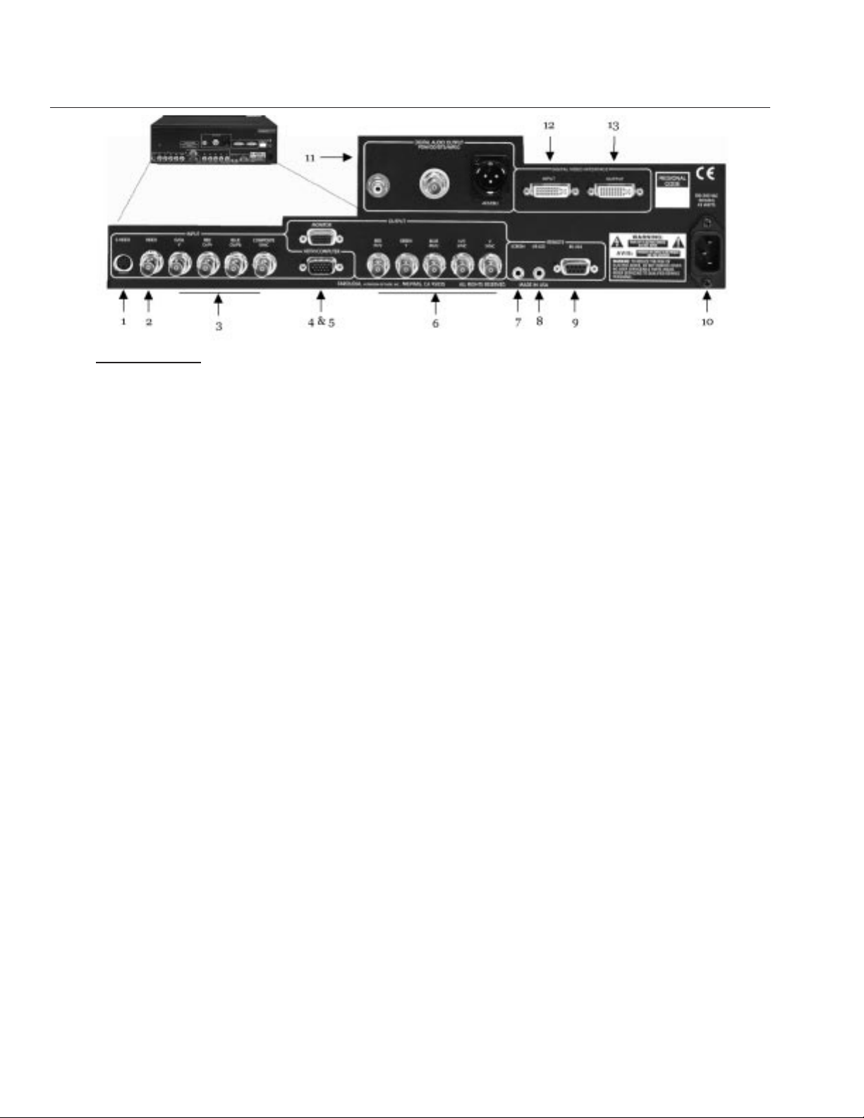
REAR PANEL I/O
1. S-Video (4 Pin DIN) Input
2. Composite Video (BNC) Input
3. Interlaced or Progressive Component or RGBs
Video Input (BNC)
Note: do not use the progressive output
from DVD players
4. High Resolution HDTV/Computer PassThrough Input - RGBHV or YPrPb (D15M)
5. RGBH/CV or YPrPb Output(D15F)
6. RGBH/CV or YPrPb Output (BNC)
Note: Both analog video outputs can be
used simultaneously
7. Screen Trigger 12V, 3.5mm, 2 pin,Tip=+)
8. Remote IR sensor (5V-12V, 3.5mm, Tip=+)
9. RS232 Port (D9F)
10. AC Power
11. Digital Audio Outputs (Digital Audio from
internal DVD drive only) AES/EBU, Coaxial and
BNC, RCA.
12. Digital Video Interface Input and Output.
CONNECTIONS
CONNECTIONS
Because of the high performance of the NRS-DCS
unit it is very important to use the highest quality
cables possible, for both input and output signals.
Both the RGB BNC and the D15 Monitor output
connections are active at all times and can run two
displays simultaneously.
To avoid AC ground loop problems, the source
equipment, NRS-DCS unit and projector should all
be running on the same grounded AC power line
(one rated for the power requirements).
1. S-Video input (Y/C) for sources such as DVDs,
Satellite systems, S-VHS tape decks (when
using S-VHS tapes only), Hi-8 tape decks.
2. Composite video input for sources such as
Laserdisc players, cable TV, VHS tape decks,
8mm tape decks.
Note: Due to the unstable nature of the VHS
format, the image may become unstable
during FFW, RW, and Pause modes depending on the player used.
3. Interlaced or Progressive Component (YPrPb) or
RGBs video input for sources such as DVDs or
high resolution YPrPb sources from HDTV satellites. Input auto-detects input type: 480i/576i
sources are sent to the internal processor,
progressive sources are routed to the PassThrough. A readout of the signal detected will
be displayed on the front panel LCD.
4. High scan rate input for sources such as HDTV
signals or computers are passed-through to the
projector. YPrPb from HDTV sources can be
transcoded to RGBHV, as well.
5. D15F connector output for use with computer
monitors or to a second display device. Use
only short cable runs.
6. BNC connectors for main output to display
devices. Cable runs up to 100ft are okay if good
quality cables are used. For YPrPb outputs use:
Red = Pr Green = Y Blue = Pb
Note: If HDTV or Computer signals are to be
used, separate H & V sync cables must be
connected to the display.
7.12V trigger to activate automatic screen relays.
Voltage is constant when unit power is on.
8. IR receiver connection allows for use with
external IR receivers so unit can be installed
behind walls.
9. RS232 D9F connection for use with RS232
control systems
10. AC Power connection.
11. Digital Audio outputs from internal DVD drive:
Coaxial (RCA, BNC) and AES/EBU. Be sure
the audio decoder is compatible with the
output used. These outputs are always active.
12. Digital Video Interface (DVI)Input . DVI input is
for pass-though to the DVI output only. DVI to
RGB output is not available
13. DVI Output: Digital interface for compatible
displays. All analog and digital inputs are output through this connection. Maximum cable
length is 15ft. For longer lengths a distribution
system or fiber optic system must be used
Note: Whether the DVI or analog RGBHV outputs
are used must be selected in the Setup
menu prior to use of the processor.
4
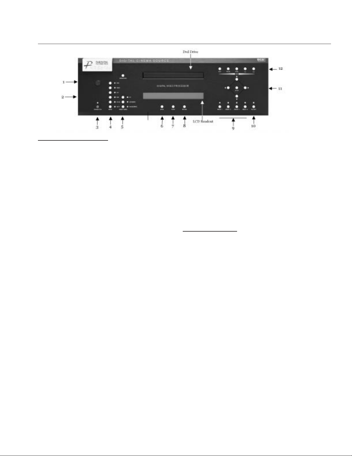
FRONT PANEL CONTROL
FRONT PANEL CONTROL
1. Infrared Receiver / Flasher window
2. Firmware Reset: push a small paper clip into
this opening to reset the unit’s CPU.
3. Power/Standby: Press to turn the unit On
(LED turns Green) or to Standby (Red)
4. Input Selection
5. Aspect Ratio Selection: If an aspect ratio is not
available (LED is not activated), it cannot be
selected.
Note: The screen shape used in the installation
must be set in the Setup Menu during
installation for proper Aspect Ratio mapping.
Anamorphic Aspect Ratio with 4:3 screens and
the Wide-4:3 settings are not available on units
with scan rates 480p, 540p, 600p and Frame
Doubling. See Setup section for details.
Note: Do not leave a 4:3 image with a Wide Angle
screen on for long periods of time on a CRT
projector or plasma display. This can cause
permanent image burn-in. Image burn-in is
not covered by Faroudja’s warranty.
6. Menu: Accesses DVD Menu when the internal
DVD drive is selected and a DVD disc is playing.
Menu does not function with other inputs or
when there is not a DVD disc in the player.
7. Setup: Accesses the various Setup menus in
the processor: System Setup, DVD Setup, IR
Setup and Test Patterns. See each section in
this manual for details.
8. Return: Pressing this button from any location
in any menu returns the front panel controls to
the User menu.
9. Custom Presets: There are a total of four custom presets that store all image and setup parameters and includes the Input. In addition, when
changing inputs, the last used setting for each
input will be recalled even if the settings were
not stored in a Preset.
10. Factory Preset: Recalls all settings to Factory
levels. Pressing once while adjusting a setting
will recall that setting back to the factory
default. Pressing the Factory button twice
returns all image settings to the factory default.
STORING PRESETS
• Adjust the image and other parameters as
needed.
• Press the Enter button, the Preset LEDs turn
Red. (Press Enter again to cancel procedure)
• Press the Preset you want to use and the LED
on that Preset will turn green, storing the preset.
11. Directional buttons and Enter: These buttons
have multiple uses. While viewing any input,
pressing the Up/Down buttons will select the
User Menu Functions ( Contrast, Brightness,
etc), pressing the Left/Right buttons will
change the Values of the Functions. When in
the different Setup menus (System Setup,
DVD, etc) the directional buttons will navigate
within those menu choices. Press the Enter
when prompted by the menu to select the
Function listed.
12. DVD Transport buttons: These will control the
internal DVD drive. Pressing the Play button
will switch the input of the processor to the
DVD input. See the DVD portion of the manual
for details.
5

SYSTEM FIRMWARE SETUP
SYSTEM FIRMWARE SETUP
Now that all the sources and cables are
connected, the processor’s firmware needs to be
fine-tuned for the installation. The System Setup
menu is only accessible from the front panel.
RS232 commands can also be used.
Be sure to go through the Setup menu before
doing the final setup of the display.
To enter the System menu, press the Setup
button and then Enter
There are four sections to the System Setting.
Pressing the Enter key to open that set of
Functions:
• System Menu
• User Mode
• I/R Setup
• Test Patterns
Pressing the Up button will recall the available
Functions. Press the Left or Right keys to select or
change values. When no commands are entered
after a short period the front panel LCD will switch
to the main window. Just hit the Up or Down buttons to jump back to the control menu last used.
SYSTEM MENU FUNCTIONS
Screen Shape
4:3 / WideScreen / Wide 4:3
4:3 – Choose this when the projector is 4:3
and the screen is 4:3
Example:: using a 1024x768 digital projector on a
4:3 screen.
WideScreen-Choose this when the screen is
Widescreen and the projector will provide the
anamorphic vertical squeeze.
Example: A 16:9 plasma, a digital or CRT
projector set to Anamorphic using a wide angle
screen or when using a Panamorph lens.
Wide 4:3-choose this when the projector is
4:3 only and the screen is Widescreen.
(Not available on units scanning at rates
below 720p)
Example: A digital projector that is 4:3 only with a
wide angle screen.
Initial Storing of the main Screen Shape.
The NRS-DCS allows for storing different screen
shapes in the Custom Presets such as with instal-
lations where two different display types are used.
Step one is to set the main screen shape:
• Select an Input (not Pass-Through)
• Enter the System Setup Menu
• Select desired Screen Shape
• Use the Function keys to select
Save to All and press Enter
The screen shape is now stored for all
Inputs and Presets.
Storing a second screen shape in
the Custom Presets
A secondary screen shape or position setting or
blanking setting can be saved as a Custom Preset:
• Enter the System Menu and choose the new
settings
Note: Do NOT use the Save to All command)
• Press Return
• Press Enter, then press Preset 1-4
Output Select - Analog/Digital
This must be selected to determine if the Analog
((BNC/D15) or Digital (DVI) outputs are used.
Both outputs cannot be used at the same time.
When DVI is selected the following controls are not
available:
Output Format, Sync on Green and Sync on H.
Save to All – Press Enter
Saves System setup (screen shape, blanking,
image position) to all presets.
Be sure to do this when initial installation is
completed.
I/R Receiver – On/Off
Controls front panel IR receiver
RS232 Echo:
On(Default)/Off
Select if the RS232 commands returns a status
report to the control system.
DCDi Mode:
On (Default)/ Off
Should always be On
Film Mode:
On (Default)/Off
6

SYSTEM FIRMWARE SETUP
7
Should always be On
LCD Display Backlight Timer
5-255 seconds (Default 10)
Sets how long the front panel LCD stays on.
Red LED Brightness
0-15 (Default 8)
Front panel LED brightness
Green LED Brightness
0-15 (Default 8)
Front panel LED brightness
OSD Vertical Position
0-255(0=Top)
This sets the single line adjustment OSD position.
OSD Timer
4-255 seconds (10 Default)
HDTV Ext. Format
480p / 720p / 1080i
This option is accessible and only needs to be
set if the Transcode option is selected for the
pass-thru.
HDTV External Input (D15) (Pass-Through)
Pass-thru / YPrPb to RGB
HDTV Component External Input (BNCs)
Pass-thru / YPrPb to RGB
Note: When the component BNC inputs auto-
detect a HDTV signal then this command
is activated as the signal is sent to the
pass-though
Note: The HD Pass-through inputs can transcode
YPrPb HDTV signals to RGBHV. It cannot
transcode RGBHV signals to YPrPb. Sync
on Green is NOT available when using the
HD Pass-through input.
Note: Blanking and image position controls can be
returned to the Factory default setting by
pressing the Factory button when accessing
that control.
Bottom Blanking
This adjusts the bottom edge blanking
Right Blanking
Adjusts the right edge blanking
Left Blanking
Adjusts the left edge blanking
Top Blanking
Adjusts the top edge blanking
Blanking Gray Level
This adjusts the blanking from black to white. This
can be used to create a gray side bar for use with
4:3 aspect ratio sources on wideangle screens to
help prevent image burn-in.
Vertical Sync Polarity
Negative / Positive
Changes sync polarity which may be needed for
compatibility with some displays.
Horizontal Sync Polarity
Negative / Positive
Changes sync polarity which may be needed for
compatibility with some displays.
Y/C Delay Adjustments: The following commands
allow for aligning the RGB color timing to the
luminance timing. These adjustments should only
be done by a qualified technician. A Y/C delay test
pattern must be used for proper alignment, such
as the Y/C delay pattern in the AVIA test DVD. The
range of adjustment is 0-6, 3 is the default center
and the timing can be adjusted +-3 steps. Be sure
to adjust the Green position first.
Blue Y/C delay
0-6, 3 default
Red Y/C delay
0-6, 3 default
Green Y/C delay
0-6, 3 default
Sync on Green
On/Off(Default)
Vertical Position
0-64, 32 default
Moves image up from center
Horizontal Position
0-170, 85 default
Moves image left or right of center
Note: moving the image too far to the left or right
can cause the display to stop working. Use
positioning controls in the display first–
if available.
RGB Input Sync
Sync on Green / Ext. Sync High / Low
(Low sync is used with PAL sources where
composite video is applied as sync with RGB)
Sync on Y
Bi-level
Tri-level

OPERATING THE PROCESSOR
to either increase detail or to help clean up poor
quality video material. It is recommended that
adjustments be made in small increments until
the desired results are achieved and then store
these custom settings in the Presets. It is
important to not use too much Detail as the
image will start to look artificial.
Digital displays will need less detail than analog
displays. High quality software will need less
detail than poor quality ones. Reducing the
detail level can help to reduce the visibility of
MPEG artifacts on artifacts on DVDs, Satelite
and cable systems. The best results are by
adjusting the levels to the software being
viewed instead of using just test patterns.
Tint
0-255, Factory 128
Tint is not available with YPrPb sources
Color
0-255, Factory 128
Contrast
0-155, Factory 110
Brightness
0-170, Factory 128
Note: It is best to set Brightness and Contrast lev-
els using the controls of the display with the
proper test pattern and with the NRS-DCS in
the factory default setting. This means that
when the Factory preset button is pressed, the
system is back to the original optimum settings.
Note: When the HD/PC or YPrPb pass through is
selected, the OSD and image adjustment
controls are not functional.
IR REMOTE AND OSD OPERATION
There are two remotes that ship with the NRS-DCS
processor. The eight button remote is used to only
control the NRS-DCS processor operations.
The large remote only controls all the operations
for the DVD transport.
Note: This option is visible only on 540p and
720p units when the YPrPb output format
is selected.
Composite Sync on H
On/Off(Default)
Note: Comp. Sync on H and Sync on Green
Functions are only available if RGB output is
selected. Both should be set to off if HDTV
or computer signals will be used for the
pass-through input
Output Format
RGB(Default)/YCrCb/YPrPb
Input Format
Auto NTSC/PAL(Default), NTSC, PAL,
PAL N, PAL M
OPERATING THE PROCESSOR
User Menu
There are three ways to control the unit: from the
front panel, from the remote using the On-ScreenDisplay and via RS232.
These are the image adjustment controls that are
used most often. To access the image controls,
press the Up or Down key on the directional keypad. Keep pressing to toggle through the available
Functions. Use the Left or Right keys to adjust.
Advanced Color System
Factory/DVD Animation
For some very high quality DVDs the Faroudja
patented chroma edge processing circuits can be
turned off (DVD Animation). For most sources, the
Factory setting should be selected. These settings
can be stored as a User Preset.
Noise Reduction
0-15, Factory 8
This sets the threshold for the Detail circuit and
interacts with the detail setting. For most sources
this setting should not be changed.
Detail
0-31, Factory 8
Note: The Detail circuit is a powerful tool for image
quality. The settings have been optimized for the
scan rate and resolution for most displays and
sources. However, the viewers tastes and the
types of software and display type require
making adjustments of these settings to fine
tune the image. These controls are very effective
8
IR REMOTE AND OSD OPERATION
This section describes the operation of the NRSDCS processor and remote. See the DVD section
starting on page 11 for details on the operation of
the DVD transport and remote. The IR remote
teaching starts on page 42.
When the unit is first plugged in it will go through
an initializing procedure and display the output
resolution. Do not send any commands to the unit
during this initialization period. Once this initialization is completed the unit is instant-on.
The remote control allows for easy operation by
simple navigation through the On Screen Display
(OSD) menus. Repeated Pressing of a button toggles through the available choices.
Power On/Off: Press Power
Select Presets: Press Preset
Select Input: Press Input Mode
Activate OSD: Press Menu
Select OSD Functions:
Press Function Up/Down
Change Value: Press Value Up/Down
On Screen Display
Control of many functions can be done using
the remote to interact with the OSD.
Accessing the OSD
• Press Menu button to bring up main Index.
• Use Function keys until the triangle at
the top of the OSD turns yellow.
• Use the Value keys to move the tringle
to select a different index and the available
control menu drops down.
• Press Function again to select an adjustment.
• Use Value to adjust. The main menu drops away
and a single line menu appears.
• Use the Function keys return to
the drop down menu.
• Press Menu again to cancel OSD
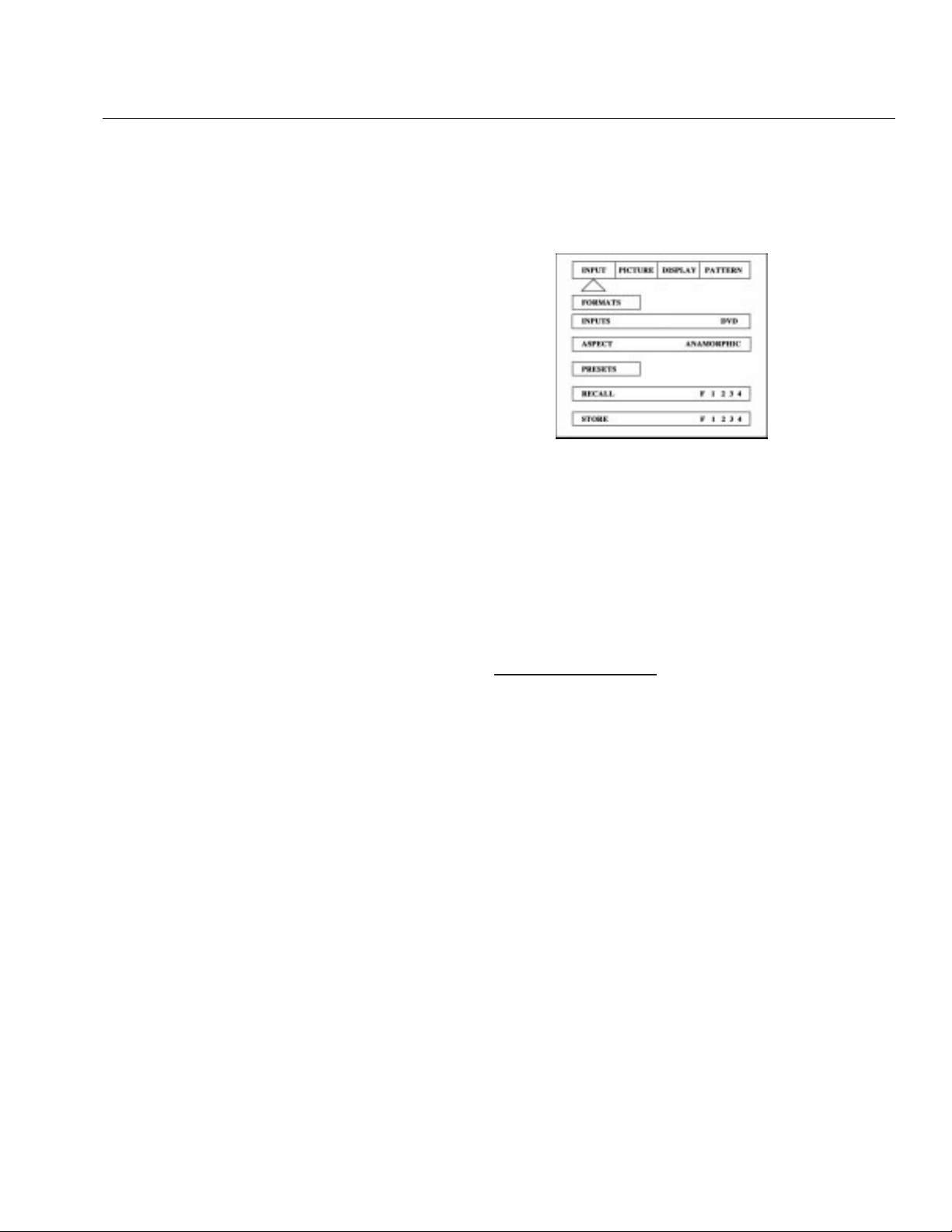
The OSD consists of four index tabs:
I
nput – Picture – Display – Patterns
Input OSD
FORMATS
Input Select:
DVD-Video-S-Video-YCrCb-RGB-Pass-thru
Aspect
4:3-Letterbox-Anamorphic
Presets-
Recall: Factory-1-2-3-4
Store: 1-2-3-4
TO STORE A PRESET:
• Make all required adjustments.
• Use the Function keys to select Store 1 2 3 4.
• Use the Value keys to select the desired preset
• Press Enter
*Aspect Ratio Selection
Press the Aspect Ratio button to toggle between
the different choices on the OSD. The aspect ratio
selected needs to match the aspect ratio of the
source.
Note: When using a Wide Angle screen a 4:3
source will have black bars on the left and right of
the image. If filling the entire screen is desired,
select Letterbox. The image will fill the screen but
the top and bottom 1/3 of the image will be cut off.
For 4:3 images on wideangle screens the side bars
of the image can be changed to gray using the
Blanking level control located in the System Setup
menu.
Note: Anamorphic on a 4:3 screen is not available
on units with scan rates below 720p.
9
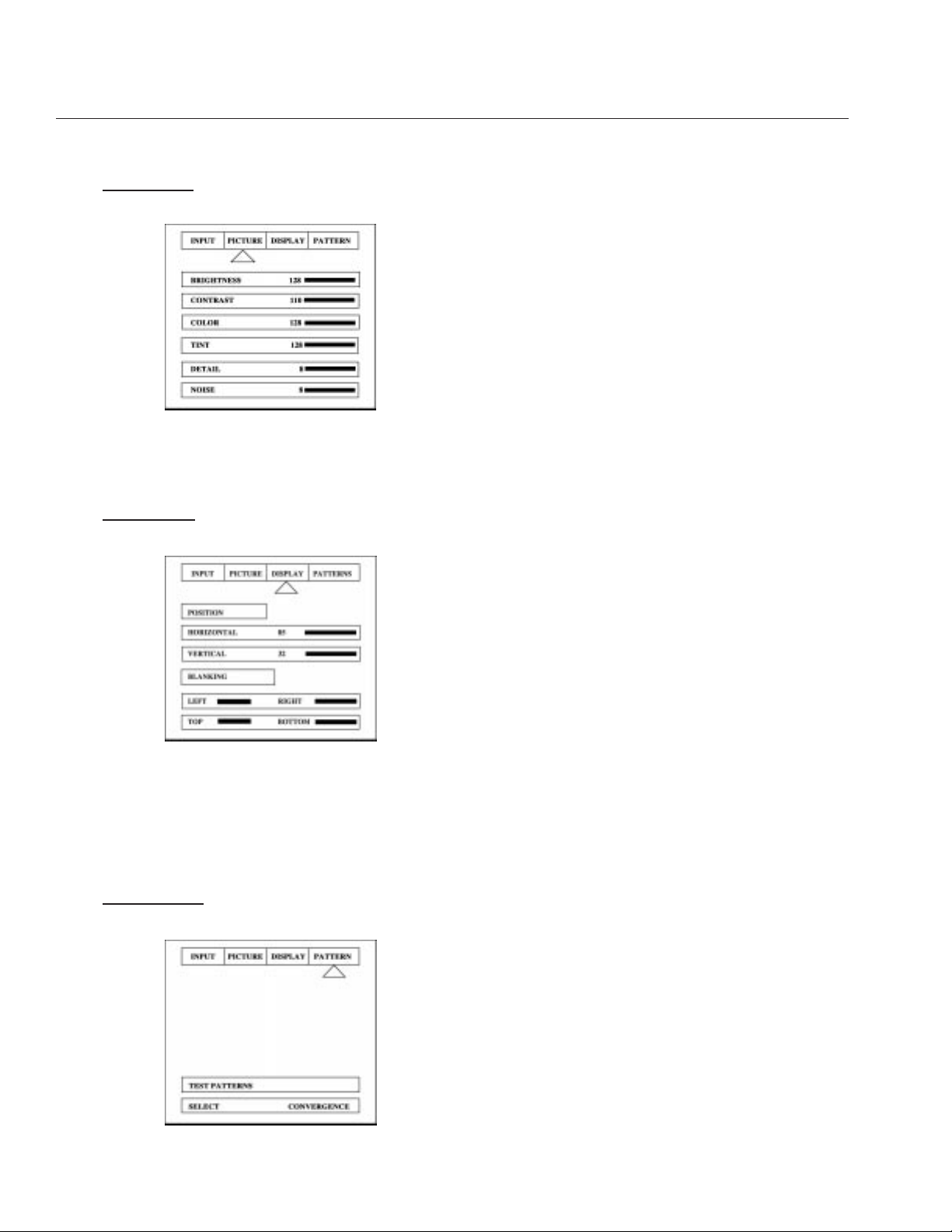
Picture OSD
Use these commands to fine tune the image
Display OSD
Use these commands to adjust the image position
and edge blanking. It is recommended to adjust
sizing and blanking in the display device first. This
should be done by a qualified technician.
Patterns OSD
These patterns are used to setup and align the
image. This should be done by a qualified
technician only.
Available Patterns:
PLUGE:
Set Brightness and Contrast
100IRE Window:
Check displays power supply
Active Borders:
Use for H&V positioning
10-step Gray Scale:
Check gray scale
Convergence:
Check convergence of display
100IRE Rev.
CB: color bars for decoder check
100IRE CB:
Color bars for decoder check
Blue Screen:
Check for defective pixels
Red Screen:
Check for defective pixels
Green Screen:
Check for defective pixels
Cr Ramp:
Check linearity of Cr channel
Cb Ramp:
Check linearity of Cb channel
Luma Ramp:
Check linearity of Luma channel
Use these patterns to adjust the image and
processor. Use the Function key on the remote to
the Select bar after activating the test patterns.
Use the Value key to select the test patterns.
Select the Picture menu to adjust the image. Store
the new settings in a preset. Then be sure to return
to the patterns menu to turn off the test patterns.
10
IR REMOTE AND OSD OPERATION
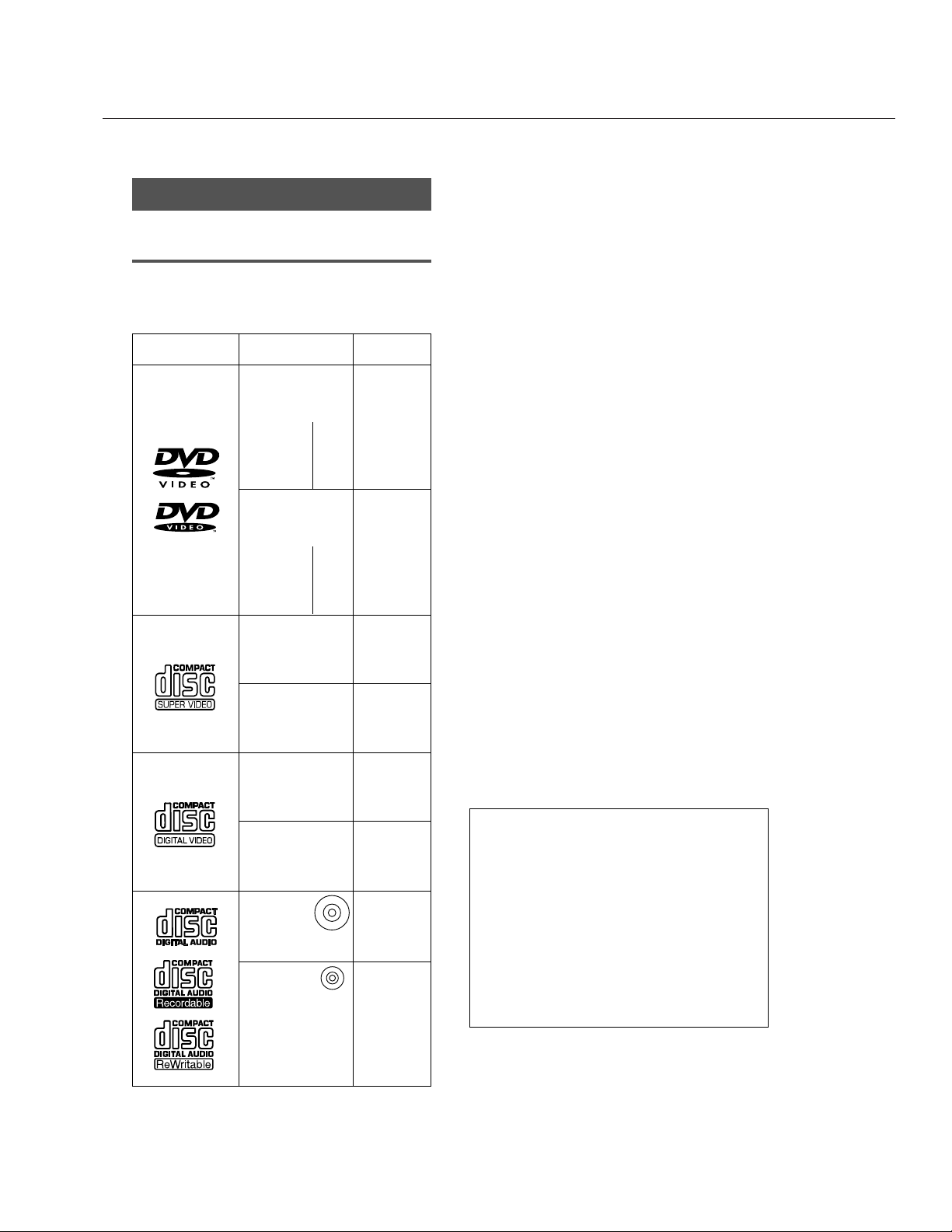
Features of This Player
Compatible with DVD, Super VCD/
Video CD and CD formats
DVD, Super VCD/Video CD and CD discs that display the
logos shown below can be played back on PIONEER
DVD players. For more information on discs compatible
with this player, refer to the table below.
The disc format logos shown above are found on disc
labels or on disc jackets.
• To prevent malfunction, do not use an 8 cm (3 in.)
adaptor (for CDs).
• Discs other than the ones indicated above cannot be
played on this unit.
• DVDs that have incompatible region numbers, DVDAudio, DVD-ROM, and DVD-RAM cannot be played on
this unit. The region number of the player can be
found on the rear panel.
*1Playing recordable CDs
This unit can play CD-R and CD-RW discs recorded in
CD Audio or Video CD format, or with MP3 audio files.
MP3 compatibility information
• The CD-ROM must be ISO 9660 compatible.
• Files should be MPEG1 Audio Layer 3 format, 44.1 or
48kHz. Incompatible files will not play and
“UNPLAYABLE MP3 FORMAT” will be displayed.
• Not compatible with some variable bit-rate (VBR) files.
• VBR files may not show play times correctly.
• This player only plays tracks that are named with the
file extension “.mp3” or “.MP3”.
• This player is not compatible with multi-session discs.
If you try and play a multi-session disc, only the first
session will be played.
• Use CD-R or CD-RW media for recording your MP3
files. The disc must be finalized in order to play.
• Audio encoded at 128Kbps should sound close to
regular audio CD quality. Although this player will play
lower bit-rate MP3 tracks, the sound quality becomes
noticeably worse at lower bit-rates.
• Only the first 8 characters of folder and track names
(excluding the “.mp3” extension) are displayed.
• This player can recognize a maximum of 250 folders
and 250 tracks. Discs containing more than 250
folders or tracks will play, but only the first 250
folders/tracks.
Caution!
• CD-R/RW discs recorded using a personal
computer or a CD recorder may not play if the disc
is damaged or dirty, or if there is dirt or
condensation on the player’s lens.
• If you record a disc using a personal computer,
even if it is recorded in a compatible format, there
are cases in which it may not play because of the
settings of the application software used to create
the disc. (Check with the software publisher for
more detailed information.)
• Unfinalized CD-R/RW discs can be played, but not
all time information (playing time, etc.) will be
displayed.
8 cm (3 in.)/
single-sided
8 cm (3 in.)/
double-sided
DVD VIDEO DVD VIDEO
Types of playable
discs and their marks
Diameter/Playable
sides
Playback time
133 min.
242 min.
266 min.
484 min.
VIDEO CD
CD
Digital audio
Digital video
(MPEG 2)
DVD VIDEO
VIDEO CD
12 cm (5 in.)/
single-sided
CD
12 cm (5 in.)/
single-sided
41 min.
75 min.
82 min.
150 min.
VIDEO CD single
CD single
8 cm (3 in.)/
single-sided
Digital audio
Digital video
(MPEG 1)
Max. 74
minutes
Digital audio
Digital video
(MPEG 1)
Max. 20
minutes
Digital audio
Max. 74
minutes
8 cm (3 in.)/
single-sided
Digital audio
Max. 20
minutes
Digital audio
(MPEG 1)
Digital video
(MPEG 2)
10 min.
Super VCD Super VCD
12 cm (5 in.)/
single-sided
Super VCD single
8 cm (3 in.)/
single-sided
Digital audio
(MPEG 1)
Digital video
(MPEG 2)
40 min.
12 cm (5 in.)/
single-sided
12 cm (5 in.)/
double-sided
1 layer
2 layer
1 layer
2 layer
1 layer
2 layer
1 layer
2 layer
*1
*1
Digital audio
Digital video
(MPEG 2)
11
DVD
What is Super VCD?
(DV-533 and DV-533K only)
This player supports the IEC’s Super VCD standard.
Compared to the Video CD standard, Super VCD offers
superior picture quality, and allows two stereo soundtracks to
be recorded. Super VCD also supports the widescreen size.
Compatible with a wide range of DVD
digital audio output formats
DVDs are recorded in one of four types of digital audio
formats (as of October 1998). The digital audio output jacks
of this player output Dolby*2 Digital, DTS*3, MPEG, and linear
PCM digital bitstreams.
TruSurround
TruSurround*4 uses technology that simulates multichannel
surround sound using only two speakers. TruSurround works
in conjunction with 2 channel audio sources to create a
realistic surround sound.
MP3 compatibility
This player is compatible with CD-R, CD-RW and CD-ROM
discs that contain MP3 audio tracks.
Easy setup and adjustment using
onscreen menus
Press SETUP on the remote control to open the Setup
screen and you’ll find setting up and adjusting the system
easy to do with on-screen menus conveniently organized and
arranged. Additionally, on-screen information (
i
) appears to
clarify the functions and explain the options available. Below
are just a few examples.
Select the type of TV screen you are
using and the preferred screen format
you’d like to use when watching DVDs
in the Video 1 menu ( pages 29 )
Answer a few questions and have all
the necessary audio, video, and onscreen language adjustments set
automatically by the player using the
Setup Navigator ( pages 17, 18 ).
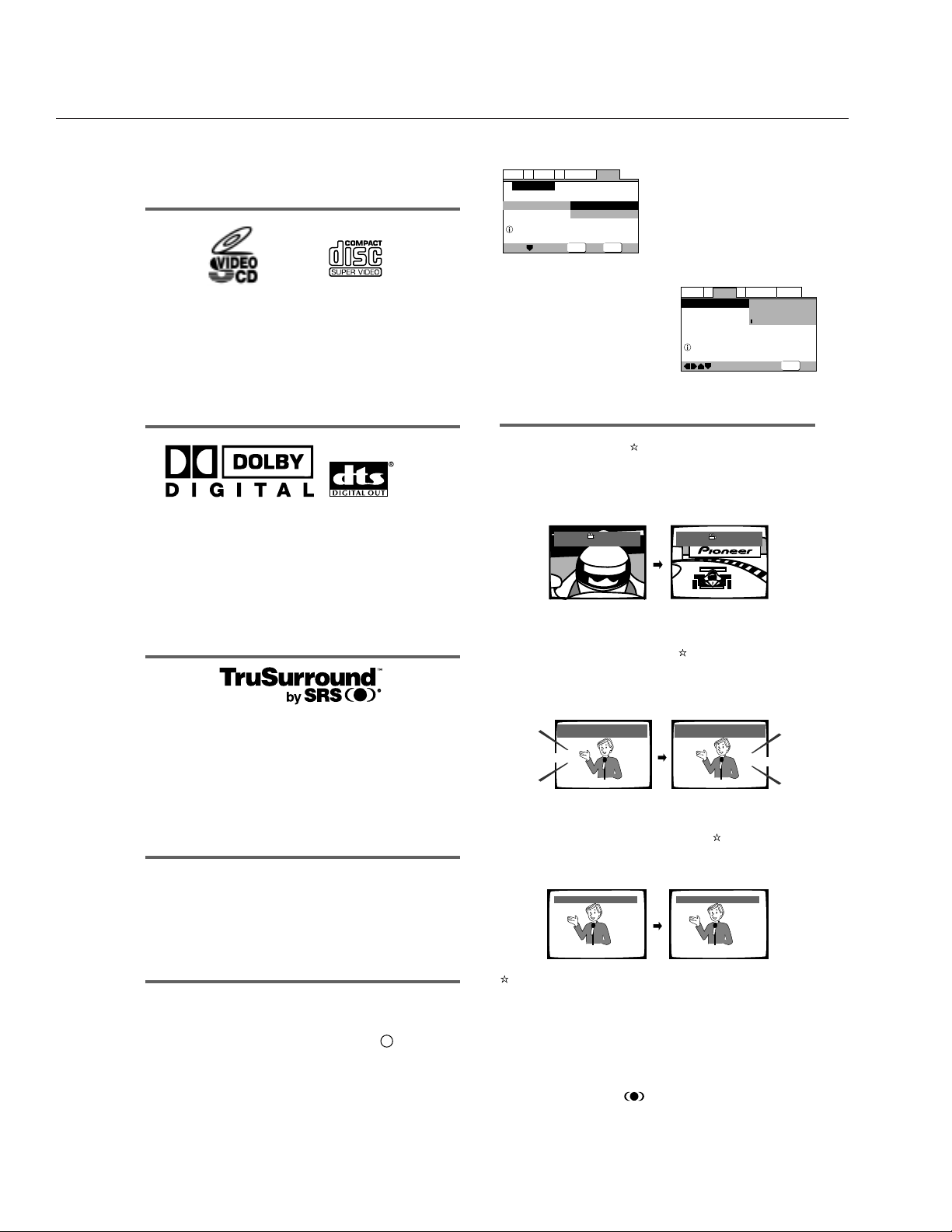
Wide range of DVD viewing options
Multi-Angle ( page 33 )
You can view scenes from different camera angles when
watching movies or other media with multiple angle playback
available.
Multiple Languages ( page 34)
You can select the language on when watching movies or
other media that have multiple language and/or audio
soundtracks recorded on them.
Multi-Language Subtitles ( page 36 )
You can select a subtitle language or turn subtitles off when
watching movies or other media with subtitles available.
This mark indicates this may not be possible with certain discs.
*
2
Manufactured under license from Dolby Laboratories.
“Dolby” and the double-D symbol are trademarks of Dolby
Laboratories. Confidential unpublished works. © 1992-1997
Dolby Laboratories. All rights reserved.
*
3
“DTS” is a registered trademark of Digital Theater Systems,
Inc.
*
4
TruSurround and the ® symbol are trademarks of SRS
Labs, Inc. TruSurround technology is incorporated under
license from SRS Labs, Inc.
General
A2
V2
Language
Audio1
Video1
Exit
Move
Select
Setup using the Setup Navigator
Setup Navigator
Setup Navigator
Start
Auto Start Off
SETUP
ENTER
—
Audio1 Video1
Language
General
A2
V2
Exit
Move
TV Screen
4:3(Letter Box)
4:3(Pan&Scan)
16:9(Wide
)
Select your display preference
SETUP
HELLO!
HOLA!
Subtitle :1 English Subtitle :2 Spanish
Angle : 2/4
Angle : 3/4
Audio : 1 English
Dolby Digital
5.1CH
Audio : 2 Spanish
HELLO
HOLA
Dolby Digital
5.1CH
12
DVD
 Loading...