

Page 1
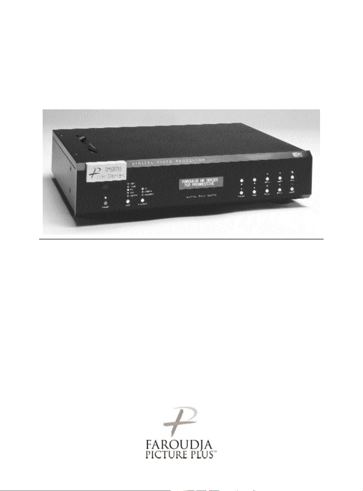
Native Rate Series
Native Rate Series Plus
Digital Video Processor
Installation and
Operations Manual
Page 2

Page 3

Inventory List / Unpacking. . . . . . . . . . . . . . . . . . . . . . . . . . . . . . . . . . . . . . . . . . . . . . . . . . . . . . . . 2
Installation . . . . . . . . . . . . . . . . . . . . . . . . . . . . . . . . . . . . . . . . . . . . . . . . . . . . . . . . . . . . . . . . . . . . 2
Front Panel Control and Set up. . . . . . . . . . . . . . . . . . . . . . . . . . . . . . . . . . . . . . . . . . . . . . . . . . . . 4
System Menu. . . . . . . . . . . . . . . . . . . . . . . . . . . . . . . . . . . . . . . . . . . . . . . . . . . . . . . . . . . . . 5
Test Patterns . . . . . . . . . . . . . . . . . . . . . . . . . . . . . . . . . . . . . . . . . . . . . . . . . . . . . . . . . . . . . 6
User Mode. . . . . . . . . . . . . . . . . . . . . . . . . . . . . . . . . . . . . . . . . . . . . . . . . . . . . . . . . . . . . . . 6
IR, Teaching . . . . . . . . . . . . . . . . . . . . . . . . . . . . . . . . . . . . . . . . . . . . . . . . . . . . . . . . . . . . . . 7
Appendix B . . . . . . . . . . . . . . . . . . . . . . . . . . . . . . . . . . . . . . . . . . . . . . . . . . . . . . . . . . . . . 11
On-Screen-Display and Remote Operation. . . . . . . . . . . . . . . . . . . . . . . . . . . . . . . . . . . . . . . . . . . 7
RS232 Commands . . . . . . . . . . . . . . . . . . . . . . . . . . . . . . . . . . . . . . . . . . . . . . . . . . . . . . . . . . . . . 8
Appendix A . . . . . . . . . . . . . . . . . . . . . . . . . . . . . . . . . . . . . . . . . . . . . . . . . . . . . . . . . . . . . 10
Specifications . . . . . . . . . . . . . . . . . . . . . . . . . . . . . . . . . . . . . . . . . . . . . . . . . . . . . . . . . . . . . . . . . 9
Warranty . . . . . . . . . . . . . . . . . . . . . . . . . . . . . . . . . . . . . . . . . . . . . . . . . . . . . . . . . . . . . . . . . . . . 12
Copyright ©2002 by Faroudja Laboratories Inc.
No part of this document may be copied, photocopied, translated, or reproduced to any electronic medium or
machine readable form without prior consent, in writing, from Faroudja Laboratories, Inc.
The Faroudja name, logo and Picture Plus are registered trademarks of Faroudja, Inc.
Specifications subject to change without notice. All Rights Reserved.
The Faroudja Laboratories NR Series is covered by the following United States patents:
4,030,121, 4,179,705, 4,240,105, 4,262,304, 4,847, 681, 4,864,389, 4,876,596, 4,893,176, 4,916,526,
4,967,271, 4,982,280, 4,989,090, 5,014,119, 5,025,312, 5,159,451, 5,237,414.
A Division of Sage, Inc.
Made in USA
TABLE OF CONTENTS
1
Rev. 01/02
Page 4
UNPACKING
Remove the NR Series unit from the shipping container and examine it for any signs of shipping
damage or missing items (check inventory list
below). All shipping materials should be saved if
the unit is to be moved or returned for service.
INSTALLATION
The processor can be either placed on a table or
rack mounted. If the rack mounting installation kit
is used, the rack mount ears are mounted by using
3 screws. It will be necessary to support the rear of
the unit if it will be shipped in the rack by using
rack support rails supplied by the rack manufacturer.
VENTILATION
The unit uses convection to cool. A fan is not
needed. As hot air raises out of the top vent, cool
air is drawn in from the bottom. These vents must
not be blocked. When rack mounted, a minimum
of 1.75” (1 rack unit height) of free space is
required above and below the unit to allow for
proper cooling. A forced air fan should be added
to the rack installation if power amps are located in
the same air space.
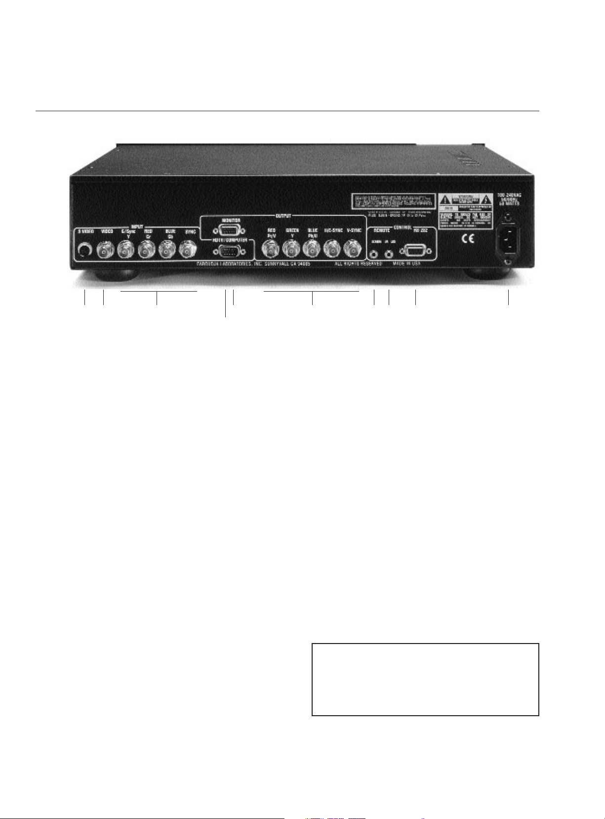
REAR PANEL I/O
Inputs
1. S-Video (4 Pin DIN)
2. Composite Video (BNC)
3. Interlaced Component (480i) or RGBs Video
(BNC)
4. HDTV/Computer (D15M)
10. AC Power
Outputs
5. RGBH/CV or YPrPb (D15F)
6. RGBH/CV, or YPrPb (BNC)
Note: Both outputs can be used simultaneously
Control
7. Screen Trigger (12V, 3.5mm, 2 pin, Tip=+ )
8. Remote IR sensor (5V-12V, 3.5mm, Tip=+)
9. RS232 Port (D9F)
2
INSTALLATION
Inventory
1-NR Series Unit 1- Remote + Batteries
1-Owner’s Manual 1- Warranty Card
1- Power Cord
12 3
4
56789 10
Page 5

INSTALLATION
3
CONNECTIONS
Because of the high performance of the NR Series
unit it is very important to use the highest quality
cables possible, for both input and output signals.
Both the RGB BNC and the D15 Monitor output
connections are active at all times and can run two
displays simultaneously.
To avoid AC ground loop problems, the source
equipment, NR Series unit and projector should all
be running on the same grounded AC power line
(one rated for the power requirements).
SOURCE INPUTS
1. S-Video (Y/C) sources such as DVDs, Satellite
systems, S-VHS tape decks (when using S-VHS
tapes only), Hi-8 tape decks.
2. Composite video sources such as Laserdisc
players, cable TV, VHS tape decks, 8mm tape
decks.
3. Interlaced Component (480i) or RGBs video
sources such as DVDs and professional
cameras. (Will not accept progressive or HDTV
signals)
4. High scan rate sources such as HDTV signals or
computers as a pass-through to the projector.
YPrPb from HDTV sources can be transcoded
to RGBHV on the output.
OUTPUTS
15. D15F connector for use with computer moni-
tors or to a second display device.
16. BNC connectors for main output to display
devices. For YPrPb outputs use:
Red = Pr
Green = Y
Blue = Pb
Note: If HDTV or Computer signals are to be
used, the projector must have separate
H & V sync cables installed.
CONTROL
17. 12V trigger to activate automatic screen relays.
Voltage is constant when unit power is on.
18. IR receiver connection allows for use with
external IR receivers so unit can be installed
behind walls.
19. RS232 D9F connection for use with RS232
control systems
10. AC Power connection.
Note: Be sure to set the proper screen shape
for the installation before beginning
any other adjustments. See the Setup
menu list.
12 3
4
56789 10
Page 6

4
FRONT PANEL CONTROL
1. Power/Standby: Press to turn the unit On (LED
turns Green) or to Standby (Red)
2. Infrared Sensor/Flasher window
3. CPU Reset: push a small paper clip into this
opening to reset the unit’s CPU.
Note: Do not activate the CPU Reset without
first contacting Faroudja technical support or
your installer. This will reset all parameters to
the factory default and may cause compatibility
issues with your setup.
4. Input Select: Toggles through the different
inputs.
5. Aspect Ratio Select: Toggles through the
available aspect ratios. If an aspect ratio is not
available (LED is not activated), it cannot be
selected.
NOTE: Anamorphic with 4:3 screens and the
Wide-4:3 settings are not available on units with
scan rates 480p,600p and Frame Doubling.
NOTE: Do not leave the 4:3 image with a Wide
Angle screen on for long periods of time on a CRT
projector. This can cause permanent image
burn-in. Image burn-in is not covered by
Faroudja’s warranty.
16. LCD Status Display: Displays scan rate on
power-up and the current Function or Value
selected.
17. Function Up/Down : Cycles up or down
through the available control Functions
18. Value Up/Down : Adjusts the levels or
changes settings of the Function selected.
19. Custom Presets: Four presets per input.
10. Enter: Press to store presets or to enter
menus.
11. Factory Preset: Recalls all settings to Factory
levels. Pressing once while adjusting a setting
will recall that setting back to the factory
default. Pressing the Factory button twice
returns all image settings to the factory default.
Storing User Preset
There are a total of 32 presets that can be stored,
four for each input (Composite, S-Video, YCrCb
and RGB with separate banks for NTSC and for
PAL). Each preset stores all image adjustment
functions.
To store a preset:
• Select the proper input.
• Make all required adjustments.
• Press the Enter button, the Preset LEDs turn
Red, the Enter LED turns Green. (Press Enter
again to cancel procedure)
• Press the Preset you want to use and the LED
on that Preset will turn green and the LED on the
Enter will go out.
NOTE: When Functions are accessed via the
front panel controls the On-Screen-Display is
not activated.
SETUP
123
4
567891011
Page 7

SETUP
5
SYSTEM SETTINGS AND SETUP
Setup offers functions that must be done when the
unit is initially installed. Some user features are not
available with a few of the Setup selections so this
must be done first. To prevent accidental alteration
of the setup parameters, some setup functions can
only be done from the front panel or with the
RS232 interface.
Note: When in the Setup Menu, pressing ENTER
three times "Escapes" the Setup Menu and
Recalls start of the User menu
System Settings - Press Enter
There are four sections to the System Setting:
• System Menu
• User Mode
• I/R Setup
• Test Patterns
System Menu - Press Enter
Pressing the Function Up will recall the following
commands in this order. Press the Value Up or
Down key to select or change values. When no
commands are entered after a short period the
front panel LCD will switch to the main window.
Just hit Function or Value to jump back to the
control menu last used.
Note: Screen Shape must be set first before any
other adjustments are made.
Screen Shape
4:3 / Wide Screen / Wide 4:3
• 4:3 – Choose this when the projector is 4:3 and
the screen is 4:3
Example: using a 1024x768 digital projector on a
4:3 screen.
• Wide Screen-Choose this when the screen is
Widescreen and the projector will provide the
anamorphic vertical squeeze.
Example: A 16:9 plasma, a digital or CRT projector
set to Anamorphic using a wide angle screen
• Wide 4:3-choose this when the projector is 4:3
only and the screen is Widescreen. (Not available
on units scanning at rates below 720p)
Example: A digital projector that is 4:3 only with a
wide angle screen.
Storing the Screen Shape
Note: The Factory Default screen shape for all NRS
units is 4:3. If that is the desired screen shape to
be used, the following steps are not required.
• Select an Input (not Pass-Through)
• Enter the Setup Menu
• Select desired Screen Shape
• Press the Function Keys to select Save to All
and press Enter
The screen shape is now stored for all Inputs and
Presets.
Storing the Screen Shape into a Preset
• Enter the Setup Menu and select a new Screen
Shape
(Note: Do NOT use the Save to All command)•
Press Enter 3 times to return to the User Menu
• Press Enter, then press Preset 1-4.
The new screen shape is now stored in the preset
selected. Pressing another preset or changing
inputs will recall the primary screen shape.
Exit System Settings- press Enter
Returns to the User Menu
Save to All – Press Enter
Saves System setup ( screen shape) to all presets
I/R Receiver – On/Off
Controls front panel IR receiver
RS232 Echo:
On(Default)/Off
Select if the RS232 commands returns a status
report to the control system.
DCDi Mode:
On (Default)/ Off
Should always be On
Film Mode:
On (Default)/Off
Should always be On
LCD Display Backlight Timer
5-255 (Default 10)
Sets how long the front panel LCD stays on.
Red LED Brightness
0-15 (Default 8)
Front panel LED brightness
Green LED Brightness
0-15 (Default 8)
Front panel LED brightness
OSD Vertical Position
Page 8

0-255(0=Top)
This sets the position of the single line
adjustment OSD
OSD Timer
4-255 seconds (10 Default)
HDTV Ext. Format
480p/720p/1080i
This option is visible and only needs to be set if
the transcode option is selected for the pass-thru.
HDTV External Input
Pass-thru
YPrPb to RGB
Note: The HD Pass-through input can transcode
YPrPb HDTV signals to RGBHV. It cannot
transcode RGBHV signals to YPrPb. Sync on
Green is NOT available when using the HD Passthrough input.
The following commands allow for separate settings for each aspect ratio but are global for all
inputs. First select the aspect ratio that needs
adjusting before beginning.
It is important that sizing and blanking adjustments
be done with the display device controls first to
insure proper settings before using the following
commands.
Bottom Blanking
Right Blanking
Left Blanking
Top Blanking
Blanking Level
This adjusts the blanking from black to gray. This
can be used to set the side bars on 4:3 sources on
a 16:9 screen to gray to prevent image burn on the
display (Firmware Rev. 2.4 or higher).
Image Vertical Position
Moves image up from center
Image Horizontal Position
Moves image left or right of center
Note: moving the image too far to the left or right
can cause the display to stop working. Use positioning controls in the display first – if available.
Pass RGB Input Sync
Sync on Green
Ext. Sync High/Low
(Low sync is used with PAL sources where com-
posite video is applied as sync with RGB)
Composite Sync on H
On/Off
Sync on Green
On/Off (Default)
(Comp. Sync on H and Sync on Green Functions
are only available if RGB output is selected.)
Output Format
RGB(Default)/YCrCb/YPrPb
Note: On 540p and 16:9HD models (Rev.2.4+),
selecting YPrPb or YCrCb adds a Function for
Tri-Level or Bi-Level sync and removes Sync-onGreen and Composite-Sync-on-H options from the
menu list. HDTV standards require Tri-Level sync
so it should be selected if there are any problems.
Input Format
Auto NTSC/PAL, NTSC, PAL, PAL N, PAL M
I/R Setup - Press Enter
Use this section to teach learning remotes the
direct access codes. See the IR Setup section on
page 10 for details.
Test Patterns-Press Enter
Use these patterns to adjust the image and
processor. Use the Value key to select the different
patterns. Once the pattern is selected press the
Function key to return to the User Menu and then
select the proper setup Function. Once adjustment
is set, use the Function key to return to Test
Patterns - Press Enter and select Test Patterns
Off. Accessing the test patterns is easiest using
the OSD.
Off
100IRE Color Bars
100IRE Reverse Color Bars
10-Step Gray Scale
Luma Ramp
Cb Ramp
Cr Ramp
Green
Red
Blue
Convergence
Active Boarders
SMPTE Color Bars
100IRE Window
PLUGE
User Mode-Press Enter
6
SETUP
Page 9

IR REMOTE AND OSD OPERATION
There are four ways to control the unit: from the
front panel, with the remote control buttons, using
the On-Screen-Display with the remote and via
RS232. Controlling from the front panel or the
remote requires cycling through the available functions. If direct access IR control is needed, the unit
can teach learning remotes via the IR flasher. See
the IR Setup section.
When the unit first powers up it will go through an
initializing procedure and then display the output
resolution.
The remote control allows for easy operation by
simple navigation through the On Screen Display
(OSD)menus. Repeated Pressing of a button toggles through the available choices.
Power On/Off: Press Power
Select Presets: Press Preset
Select Input:s Press Input Mode
Activate OSD: Press Menu
Select OSD Functions: Press Function
Change Values: Press Value
On Screen Display
Control of most functions can be done using the
remote to interact with the OSD.
Accessing the OSD
• Press Menu button to bring up main Index.
• Use Function keys to select an index and the
available control menu drops down.
• Press Function again to select an adjustment.
• Use Value to adjust. The main menu drops away
and a single line menu appears.
• Use the Function keys return to the drop down
menu.
• Press Menu to recall the main index.
• Press Menu again to remove OSD
The OSD consists of four index tabs:
The Functions available for each index are listed
below:
Formats
Input Select:
Video-S-Video-YCrCb-RGB-PassThru
Aspect Ratio*
4:3-Letterbox-Anamorphic
Presets-
Recall: Factory-1-2-3-4
Store: 1-2-3-4
To store a preset:
• Select the proper input.
• Make all required adjustments.
• Use the Function keys to select Store 1 2
3 4.
• Use the Value keys to select the desired
preset
• Press Enter
*Aspect Ratio Selection
Press the Aspect Ratio button to toggle between
the different choices. The aspect ratio selected
needs to match the aspect ratio of the source.
7
OPERATING INSTRUCTIONS
INPUT PICTURE DISPLAY PATTERNS
INPUT
These are the controls that are used most often.
Noise Reduction
0-15, Factory 8
Detail
0-31, Factory 8
Tint
0-255, Factory 128
Color
0-255, Factory 128
Contrast
0-155, Factory 128
Brightness
0-170, Factory 128
Advanced Color System
Factory/DVD Animation
For some DVDs with computer animation, the
Faroudja patented chroma edge processing circuits can be turned off. For most sources, the
Factory setting should be selected. These settings
can be stored as a User Preset.
Page 10

NOTE: When using a Wide Angle screen a 4:3
source will have black bars on the left and right of
the image. If filling the entire screen is desired,
select Letterbox. The image will fill the screen but
the top and bottom 1/3 of the image will be cut off.
Note: Anamorphic on a 4:3 screen is not available on units with scan rates below 720p.
Use these commands to fine tune the image
Brightness
Contrast
Tint
Color
Detail
Noise Reduction
NOTE: Adjusting Detail – The Detail and Noise
Reduction settings have been optimized for the
scan rate and resolution of the NR Series for most
sources. However, the viewers tastes and the
types of software used may require making
–adjustments of these settings to fine tune the
image. These controls are very effective to either
increase detail or to help clean up poor quality
video material. It is recommended that adjustments be made in small increments until the
desired results are achieved. It is important to
not use too much Detail as the image will start
to look artificial.
Use these commands to adjust the image position
and edge blanking. It is recommended to adjust
sizing and blanking in the display device first. This
should be done by a qualified technician.
Position
Horizontal
Vertical
Blanking
Left
Right
To p
Bottom
These patterns are used to setup and align the
image. This should be done by a qualified technician only.
Pattern
On/Off
Select
Off Cr Ramp
PLUGE Cb Ramp
100IRE Window Luma Ramp
Active Boarders 10-step Gray Scale
Convergence 100IRE Rev. CB
Blue 100IRE CB
Red
Green
RS232 CONTROL
Connector: DB-9 Female
Baud rate: 9600 default, 8 bit,
1 stop bit and No Parity
(Adjustable 4800, 9600, 19,200)
Pin Configuration:
Pin 5 = Ground
Pin 3 = Rx
Pin 2 = Tx
All commands are sent using ASCII text strings.
NOTE: A command must start with the
string header “NRS”
Following the header, a comma is used to delimit
the header from the command. All the commands
with their descriptions will be listed below. All the
text strings are terminated with a carriage return
(0x13). The header and command are not case
sensitive.
Since the picture settings are Input specific, the
input to be used, i.e. Video, Y/C or YPrPb, must
be selected first before adjusting and storing
settings.
See appendix A for the command list.
8
RS232
PICTURE
DISPLAY
PATTERNS
Page 11

SPECIFICATIONS
Inputs (Interlaced)
Format NTSC/PAL Auto Detect
Composite(BNC) 1vpp
S-Video Y - 1v pp
C -286mv pp
Component (SMPTE)(BNC) Y—1vpp
Interlaced (480i) Cr—700mv pp
Cb - 700mv pp
RGB Comp. Sync—1vpp
RGB-700mv pp
HD/PC Pass-Thru D15M
Remote Control “D9F” RS-232 ASCII
Outputs (Progressive)
R,G,B (BNC or DB15) 700mv pp, TTL Sync
YprPb 700mv pp, Sync on Y-1vpp
RGsB Gs - 1vpp
RGB - 700mv pp
D15F Pin Function
11 Red Out
12 Green Out
13 Blue Out
17 Red Gnd
18 Green Gnd
19 Blue Gnd
10 Sync Gnd
11 Sync Gnd
13 H Sync Out
14 V Sync Out
Horizontal Sync: NTSC: 31.5KHz, 37.7KHz, 45KHz, or 48KHz- depending on model
NTSC: 63KHz - Native Rate Series Plus only
PAL: 31.2KHz, 37KHz, 40KHz - depending on model
PAL: 53KHz - Native Rate Series Plus only 4.0 vpp TTL
Vertical Sync: 60Hz/50Hz, 4.0 vpp TTL
Composite Sync : 4.0 vpp TTL
Dimensions 13D X 17.25W X 4.24H (with feet) (Depth includes rear BNC)
Weight 15lbs, 20lbs shipping
Power Consumption 24w with 120v, 33w with 220v
Power Supply 100-240VAC 50/60Hz Auto Ranging
9
Page 12

COMMAND FUNCTION COMMAND FUNCTION
HELP Display Help Menu SYSTEM SETUP
ST Report Current Status
ON Power ON E# ECHO
0=Off, 1=On
OFF Power OFF W# Screen Shape,
(0=Wide, 1=4x3,
2=Wide-4:3)
CS# Comp Sync
0=Off, 1=On
INPUTS G# Sync on Green
0=Off, 1=On
V Video Input M# Output Mode (0-2)
(0=RGB, 1=YCrCb, 2=YPrPb)
Y S-Video Input CS# Comp Sync
0=Off, 1=On
X YCrCb
R RGBS OSD# Vertical Position (0-255)
(Default 128)
EXT Pass-Thru Input OSD# OSD
0=Off, 1=On
IMAGE CONTROL
B# Brightness (0-255) OSDT# OSD Timer (4-255)
(Factory 128) (Default 10)
C# Contrast (0-255) P# Pass-Thru
(Factory 128) R=Pass-Thru, Y=Transcode
T# Tint (0-255) TP# Internal test Pattern
(Factory 128) 0=Off
1=100% Color Bars
2=Reverse Color Bars
3=10-step Grayscale
4=Luma Ramp
5=Cb Ramp
6=Cr Ramp
7=Green
8=Red
9=Blue
10=Convergence
11=Active Boarder
12=SMPTE Color Bars
13=100% Window
14=PLUGE
K# Color (0-255) IR# IR Receiver
(Factory 128) 0=Off, 1=On
D# Detail (0-15)
(Factory 8)
N# Noise Reduction (0-15) For additional setup codes
(Factory 8) type HELP for the full list
A# Input Aspect Ratio (0-2)
(0=4x3, 1=Letterbox,
2=Anamorphic)
L# Store User Preset (1-4)
P# Recall Preset (0-4)
(1-4=User, 0=Factory)
10
APPENDIX A – RS232 CODES
Page 13

APPENDIX B – IR SETUP COMMANDS
IR REMOTE TEACHING FUNCTIONS
Use the Function key to locate IR Setup Menu-Press Enter. Use the Value key to select the different
commands. Each time the Enter button is pressed it “flashes” the commands out through the IR receiver
window on the front panel. The Number of Samples choice defines how many time the NRS will send the
sample IR command. Adjust this if learning remote does not respond properly
IR COMMAND
1 POWER ON
0 POWER OFF
3 INPUT
4 ASPECT RATIO
5 BRIGHTNESS
6 CONTRAST
7 COLOR
8 TINT
9 DETAIL
10 NOISE REDUCTION
11 FUNCTION UP
12 FUNCTION DOWN
13 VALUE UP
IR SETUP COMMANDS
11
Direct Access Infrared Commands
To turn On the unit, a sequence must be used:
Press Power + #
1 = On, 0 = Off
Note: The timing of the digits (1&0) must be
under .25 seconds after the Power command is
issued.
Note: all sequence commands listed below
should have approximately a .25 second delay
between commands.
Input Control: Input + #
1 = Composite
2 = S-Video
3 = YPrPb (YCrCb)
4 = RGB
5 = Pass-through
Aspect Ratio Control: Aspect + #
1 = 4:3
2 = Letterbox
3 = Anamorphic
IR COMMAND
14 VALUE DOWN
15 PRESET / ENTER
16 MENU
17 0
18 1
19 2
20 3
21 4
22 5
23 6
24 7
25 8
26 9
Preset Select: Preset + #
1- 4, 0 = Factory
To change Levels, a sequence must be used:
Note: All the following commands must receive
a three digit number.
Brightness + ### (0-255)
Contrast + ### (0-155)
Color + ### (0-255)
Tint + ### (0-255)
Detail + 0## (0-31)
Noise Red. + 0## (0-15)
Note: The user can also adjust levels by using
the Value Up/Down keys or store the levels in
Presets and recall those when desired.
Page 14

12
LIMITED WARRANTY
Faroudja Laboratories, Inc. (“Faroudja”) warranties that its products will be free of
defects in workmanship and material and conform substantially to published specifications under normal use and service. This warranty is made to the first purchaser
of the products and extends for twelve (12) months from the date of sale. The warranty does not apply to products damaged as a result of accident, misuse, neglect,
alteration, improper installation, unusual physical or electrical stress or unauthorized
repair. Image burn-in on display devices is not covered under warranty. All warranty
claims should be made at the place of purchase. No products may be returned to
Faroudja without it consent. If requested by Faroudja, purchaser agrees to provide
proof of purchase and to return defective products to Faroudja, transportation
charges prepaid. Faroudja’s only liability with respect to products that do not meet
the foregoing warranty, and for which appropriate transportation arrangements have
been made, will be to repair or, at Faroudja’s option, replace defective products or
portions thereof.
THE FOREGOING WARRANTY IS IN LIEU OF ALL WARRANTIES EXPRESSED,
IMPLIED OR STATUTORY, REGARDING THE PRODUCTS, AND ALL IMPLIED
WARRANTIES, INCLUDING, WITHOUT LIMITATION, ANY IMPLIED WARRANTIES
OF MERCHANTABILITY OR FITNESS FOR A PARTICULAR PURPOSE AND ANY
OTHER WARRANTY OBLIGATIONS ON THE PART OF FAROUDJA.
IN NO EVENT WILL FAROUDJA BE LIABLE FOR LOSS OF PROFITS OR
GOODWILL, OR DIRECT, INDIRECT, INCIDENTAL, CONSEQUENTIAL OR
SPECIAL DAMAGES OF ANY KIND, HOWEVER CAUSED, WHETHER BY
FAROUDJA’S BREACH OF WARRANTY OR BY FAROUDJA’S SOLE OR
CONCURRENT NEGLIGENCE OR OTHERWISE.
FAROUDJA may change product specifications and warranty policy at any time
without notice.
Faroudja Laboratories
750 Palomar Ave., Sunnyvale, California 94085
Tel: 408-735-1492 Fax: 408-735-8571
www.faroudja.com
A Division of Sage, Inc.
Page 15

Page 16

 Loading...