

Page 1

MLP
MLP ENCODER
USER GUIDE
Page 2

Meridian MLP Encoder User Guide
i
Page 3

PREFACE
Copyright and acknowledgements
Sales and service in the UK
Meridian Audio Ltd
Stonehill
Stukeley Meadows
Cambs
PE29 6EX
England
Tel (01480) 52144
Fax (01480) 459934
World Wide Web – www.meridian-audio.com
Designed and
manufactured in the UK by
Digital Gramophone and Wireless Ltd
Stukeley Meadows
Sales and service in the USA
Meridian America Inc
3800 Camp Creek Parkway
Building 2400
Suite 122
Atlanta
GA 30331
Tel (404) 344 7111
Fax (404) 346 7111
Stonehill
Cambs
PE29 6EX
England
Copyright © 1999, 2000 Digital Gramophone and Wireless Ltd.
Part no: MLP/1
The MLP software and this
documentation are copyright materials.
No part of the MLP software may be
reproduced, transmitted, transcribed,
stored in a retrieval system, or translated
into any language, or computer
language, in any form or by any means
without the prior written permission of
Meridian Audio Ltd and its licensor(s).
Additional copies of this guide may be
made and distributed provided they
include this copyright notice.
Meridian Audio Ltd and its licensor(s)
specifically retain title to all MLP
computer software. The software
described in this guide is furnished
under a license agreement and may only
be installed, used, or copied in
accordance with the terms of that
agreement.
The information in this guide is believed
to be correct as of the date of
publication. However, our policy is one
of continuous development and so the
information in this guide is subject to
change without notice, and does not
represent a commitment on the part of
Meridian Audio Ltd or its licensor(s).
Meridian and the Meridian logo are
registered trademarks of Meridian
Audio Limited. MLP is a registered
trademark of Dolby Laboratories
Licensing Corporation, in the United
States of America, and other countries.
All other brand names, product names
or trademarks belong to their respective
holders.
This guide was produced by:
Human-Computer Interface Ltd,
www.interface.co.uk
ii
Page 4

Contents
Introduction 1
Overview of MLP 2
Other features 4
Making an MLP Stream for
DVD-Audio 5
Typical workflow 6
Encoding 7
Checking an encoded file 10
Using the MLP Encoder 13
Installing the Meridian MLP Encoder 14
Creating a new project 17
Specifying the input files 18
Specifying the encoding options 21
Specifying the channel assignments 23
Specifying the downmix 26
Specifying the output files 27
Specifying the checking options 28
Encoding the project 30
Checking the encoded file 32
Appendix A – Command-line
MLP Encoder 35
Command format 36
Input 38
Options 41
Channel assignment 44
Downmixing 46
Output 47
Encoding 48
iii
Page 5

Appendix B – Command-line
Proofing Decoder 51
Command format 52
Options 54
Output 55
Index 57
iv
Page 6

Introduction
This chapter gives an introduction to MLP, with information about its
benefits and the expected savings it achieves for different materials.
1
Page 7

INTRODUCTION
Overview of MLP
Meridian Lossless Packing (MLP) is an encoding system designed to
compress high-quality digital audio data with bit-for-bit accuracy. Unlike
perceptual, or lossy data reduction, MLP guarantees not to alter the final
decoded signal in any way, but merely packs the audio data more
efficiently into a smaller data rate.
MLP encoding provides two main benefits:
•
It minimises the size of the compressed data, allowing a larger amount
of data to be stored in a given capacity.
•
It can reduce the maximum instantaneous peak data rate.
This second feature is important for DVD-Audio which has an upper limit of
9.6Mbps. Six channels of 96kHz 24-bit Linear PCM audio have a data rate of
13.824Mbps, which is well in excess of the capability of DVD-Audio. Also at
this data rate the data capacity of the disk would limit the playing time to
approximately 45 minutes. MLP encoding can reduce the worse case data
rate to 9.6Mbps, in addition to extending the playing time to the industry
norm of 74 minutes.
The following table gives examples of the typical compression that can be
achieved with different audio sample rates and wordsizes:
Format Minimum Typical
48kHz, 16-bit 0% 50%
96kHz, 20-bit 40% 55%
96kHz, 24-bit 38% 52%
192kHz, 24-bit 43% 50%
The following table gives examples of playing times on DVD-Audio that can
be obtained with different channel, sample rate, and wordsize
combinations:
Format Playing time
6 channels, 96kHz, 24-bit 86 minutes
5.1 channels, 96kHz, 24-bit 100 minutes
2 channels, 192kHz, 24-bit 2 hours
2 channels, 96kHz, 24-bit 4 hours
2 channels, 44.1kHz, 16-bit 12 hours
1 channel, 44.1kHz, 16-bit 25 hours (talking book)
2
Page 8

INTRODUCTION
How it works
Because MLP was originally designed with consumer applications in mind,
one of its design aims is that any complexity must be in the encoder rather
than the decoder. The design of the decoder ensures that it will remain
lossless irrespective of the hardware platform or processor it is
implemented on. In addition, the decoder is driven by information in the
bitstream, allowing improved versions of the encoder to be developed
without becoming incompatible with the installed base of decoders.
MLP encoding uses a combination of three methods to reduce the data
rate:
•
Lossless matrixing is used to reduce the correlation between channels.
•
Lossless waveform prediction is used to reduce the inter-sample
correlation.
•
Entropy coding is used to reduce the data rate by efficiently encoding
the most likely occurring values in the audio data.
MLP does not make any assumptions about the assignment of channels, or
the correlation between channels, but takes advantage of whatever
redundancy is present in the overall signal to encode the data using the
smallest possible bandwidth.
In addition to these procedures for reducing the data rate, MLP uses stream
buffering to reduce the variations in the transmitted data rates, and absorb
transients that are hard to compress, in order to ensure a maximum
instantaneous peak data rate. The buffer allows the peak data rate to be
minimised for virtually all practical audio data.
If the audio data cannot be compressed within the specified peak data rate
the MLP Encoder will signal an error. The producer can then use one or
more options for reducing the data rate, or reducing the total space used
by the recording. These include:
•
Reducing the bit width of one or more channels, such as from 24-bit to
22-bit.
•
Filtering one channel to LFE.
•
Reducing the audio bandwidth; for example, by filtering information
above some arbitrary frequency, such as 40kHz when sampling at 96kHz.
All of these options will increase the amount of compression that MLP can
achieve, thus increasing the playing time or reducing the peak data rate.
3
Page 9

INTRODUCTION
Other features
Two-channel downmix
Content providers will often want to make a two-channel version of a
multi-channel audio stream available on a DVD-Audio disk, for consumers
who only have a two-channel playback device. One option is to create
separate multi-channel and two-channel streams, and write these
separately to the disk. However, this requires two separate mastering and
authoring processes, and uses disk capacity.
MLP provides an elegant and simple solution to providing a two-channel
downmix. The encoder includes lossless matrixing, which can encode a twochannel downmix as a linear combination of the multi-channel mix and
encode this alongside the multi-channel version on the DVD-Audio disk.
The advantage of this approach is that the producer can listen to the
downmix at the encoding stage in the knowledge that it will be delivered
bit-for-bit to the end user at the decoding stage. Another advantage is that
a two-channel-only playback device does not need to decode the multichannel stream, and need only decode the stereo.
Other features
In addition to audio the MLP stream can carry hierarchical metadata, which
can include:
•
Dynamic range control data.
•
Ownership and copy protection fields.
•
Time codes.
•
Descriptive text fields.
In addition MLP has powerful built-in error detection that allows rapid
recovery from bit-stream errors, and prevents any erroneous noises, clicks,
or bangs following data errors.
4
Page 10

Making an MLP Stream for DVD-Audio
This chapter describes the workflow of an MLP encoding project for
DVD-Audio using the Windows-based MLP Encoder, together with the
MLP command-line tools described in subsequent chapters of this
guide.
5
Page 11
MAKING AN MLP
STREAM FOR DVD-
AUDIO
Typical workflow
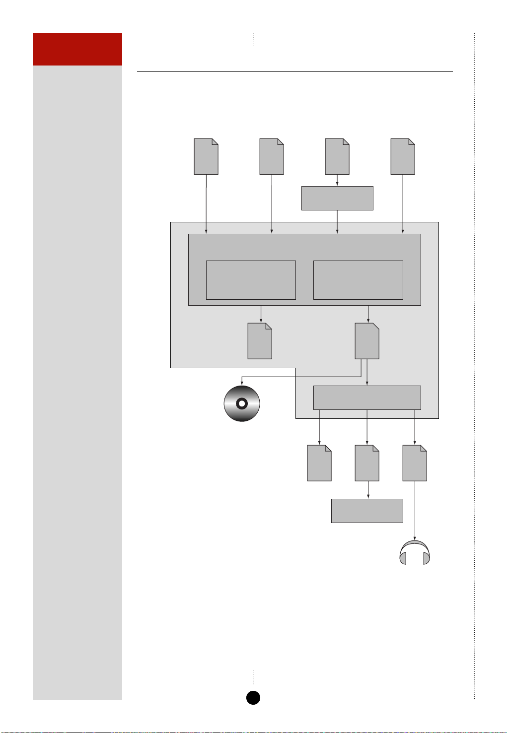
The following diagram shows a typical workflow from the input audio files
through to the output MLP file:
Input files
Encoding
MLP Encoder
DVD Audio
WAV AIFF
Compression options:
Sample rate
Word size
Channel assignments
Windows
mastering
Log
file
Sonic Solutions
Soundfiles
MULTIWAV
MLP Encoder
MLP_ENC
DVD-Audio
LPCM
Downmix options:
Matrix coefficients
MLP
file
Proofing decoder
MLPPROOF
Downmix
Log
file
WAV
file
MIXNULL
WAV
file
Listening
tests
The different sections of this workflow are explained in greater detail in
the following sections, and in the PDF files on the installation disk.
6
Page 12

MAKING AN MLP
STREAM FOR DVD-
AUDIO
Encoding
Input files
The MLP Encoder processes audio data from one or more input file. The
MLP Encoder directly supports WAV, AIFF, and LPCM (uniform-rate) audio
formats, and in addition the command-line version supports raw binary.
Files in Sonic Solutions soundfile format, or DVD-Audio LPCM mixed-rate
format, can be converted into WAV format for use with the MLP Encoder
using the command-line tools MULTIWAV and DVDWAV respectively.
MLP Encoder
The MLP Encoder is an intuitive Windows-based program that simplifies the
steps involved in encoding a set of one or more audio files, and then
checking the resulting MLP file.
To use the MLP Encoder the following options need to be specified:
Sample rate and wordsize
The sample rate and wordsize will be set to the corresponding values in the
input files.
Channel order and assignments
DVD-Audio supports up to six channels in one of 21 alternative channel
assignments.
To run the MLP Encoder you need to specify the channel assignment, and
the location of each of the channels in the source files.
7
Page 13
MAKING AN MLP
STREAM FOR DVD-
AUDIO
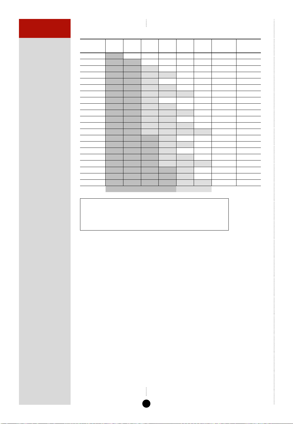
DVD-Audio channel assignments
Channel
Assign
0
1
2
3
4
5
6
7
8
9
10
11
12
13
14
15
16
17
18
19
20
Ch 0
M
L
Lf
Lf
Lf
Lf
Lf
Lf
Lf
Lf
Lf
Lf
Lf
Lf
Lf
Lf
Lf
Lf
Lf
Lf
Lf
Ch 1 Ch 2 Ch 3 Ch 4 Ch 5
R
Rf
Rf
Rf
Rf
Rf
Rf
Rf
Rf
Rf
Rf
Rf
Rf
Rf
Rf
Rf
Rf
Rf
Rf
Rf
S
Ls
LFE
LFE
LFE
Ls
Ls
Ls
Group 1 Group 2
Rs
Ls Rs
C
C
Ls
C
LFE
C
LFE
C
LFE Ls Rs
C
C
Ls
C
LFE
C
LFE S
C
LFE
C
Rs
Rs
Rs C LFE
S
S
S
Rs
S
Rs
Ls Rs
LFE
C
Number in
Group 1
Number in
Group 2
10
20
21
22
21
22
23
21
22
23
22
23
24
31
32
31
32
33
41
41
42
M MonoKey:
L Stereo Left
R Stereo Right
Lf Left front
Rf Right front
C Centre
LFE Low Frequency Effects
S Surround
Ls Left surround
Rs Right surround
Channel groups
The channel assignments group the channels into two groups, referred to
as Group 1 and Group 2. The significance of the group is that the sample
rates and wordsize can be specified independently for each group. See
DVD-Audio channel assignments, above.
The DVD-Audio channel assignments 8 to 12 are almost identical to the
channel assignments 13 to 17, and differ only in the way the channels are
grouped. For these channel assignments you therefore might want to
specify whether the number of channels in Group 1 is 2 or 3 in order to
uniquely identify the channel assignment. If this is not specified the
encoder will place as many channels as possible into Group 1.
Restart gap
A restart gap of between 8 and 32 can be specified to control the overhead
of the MLP stream. The lowest, default setting of 8 allows a restart every
7ms, and this setting gives the fastest start up in cueing and the fastest
recovery from a disk error. Selecting the highest permitted value of 32 will
increase the apparent disk capacity, but increase the recovery/cue time to
27ms.
8
Page 14

MAKING AN MLP
STREAM FOR DVD-
AUDIO
Pre-audio gap
To allow players or downstream decoders to lock onto the MLP stream it is
recommended that you include a one-second period of silence or irrelevant
audio (eg ambient noise) at the start of each track.
Downmix
To encode a downmix from the input channels you need to specify the
downmix coefficients to the encoder. Normally this will be done by
listening to a suitable mix on an audio workstation, and then reading the
fader settings. The command-line version of the MLP Encoder requires the
matrix coefficients to be specified as decimal fractions, and the following
table is provided to convert from dB values:
dB +6 +3 0 -3 -6 -9 -12 -15 -18 -21 -24 -∞
Coefficient 2.00 1.41 1.00 0.71 0.50 0.35 0.25 0.18 0.13 0.09 0.06 0.00
The Windows MLP Encoder automatically converts from dB values.
Downmix coefficients can range from +2 (ie +6dB) to 0 (ie infinite
attenuation), and from -2 to 0 for negative phase, where 1 corresponds to
0dB.
The downmix process does not prevent overload (clipping) of the stereo
output signal, because that may be the artistic intent. When overload
occurs, the signal is not clipped in the multi-channel MLP stream (which
continues to operate losslessly) but in the player. You can detect an output
clip using the Proofing Decoder, MLPPROOF.
9
Page 15

MAKING AN MLP
STREAM FOR DVD-
AUDIO
Checking an encoded file
It is strongly recommended that all encoded files be checked carefully with
the tools provided before proceeding to author them onto a DVD. The
following sequence of checks is recommended:
• Check the encoder log file for any error reports.
• Decode the encoded file using MLPPROOF and check its log file for
errors.
• Check downmixes by creating a decoded stereo WAV file of the
downmix.
• Listen to the decoded audio files.
Logging and reporting
The MLP Encoder and Proofing Decoder each produce log files to confirm
the options that have been specified, and report error messages. In the
Windows MLP Encoder the log files are displayed in the Progress dialogue
box so that any errors can be identified, as well as being saved to disk for
later reference.
MLP Encoder log
If the MLP Encoder session has been successful the last line of the encoder
log should display:
Encoding completed
If this line is missing do not proceed to decode. Check your input material is
correctly formatted (eg view it in an editor or play it back), or re-run the
encoding as an isolated process so that the error messages on the console
can be seen.
The MLP Encoder log also displays the average bits/sample achieved by
encoding.
Checking Proofing Decoder logs
The Proofing Decoder log will end with the line
PASS
if the stream is correct. Other useful information is also included in the log,
including an alert if a downmix will clip in the player, and confirmation of
the actual channel assignment, sample rates, wordsizes, and grouping.
10
Page 16

MAKING AN MLP
STREAM FOR DVD-
AUDIO
MLP file playing time
The MLP encoding process extends the audio sample by up to 1ms of
silence. The exact duration is displayed in the log for use in subsequent
authoring.
Listening tests
Listening tests are important in case the source file format was incorrect.
Checking downmixes
It is strongly recommended that all downmixes are checked using the
following procedure:
• Use the Proofing Decoder MLPPROOF to create a WAV file of the
downmix from the MLP Stream.
• Listen to the downmix and confirm it is correct.
• Check the downmix file for errors using MIXNULL.
11
Page 17

MAKING AN MLP
STREAM FOR DVD-
AUDIO
12
Page 18

Using the MLP Encoder
The Meridian MLP Encoder program provides a convenient Windows
interface to the MLP tools to simplify the creation of MLP streams for
DVD-Audio.
This chapter explains how to install the Meridian MLP Encoder, and
use it to create and check MLP streams.
13
Page 19

USING THE MLP
ENCODER
Installing the Meridian MLP Encoder
Requirements
To use the Meridian MLP Encoder, and its associated tools, you need:
•
A computer running Windows 95, 98, NT 4 or 2000.
•
A 100MHz or faster Pentium-class processor.
•
At least 16Mbytes of RAM.
•
5Mbytes of free disk space.
The graphical user interface requires a mouse or similar pointing device – it
cannot be operated solely from the keyboard.
In addition, you must have sufficient free disk space for:
•
The input audio you intend to encode.
•
The resulting MLP file.
•
Any downmix auditioning and null-checking files you wish to generate;
see Specifying the checking options, page 28.
If encoding speed is important to you, it is strongly recommended that you
fit 128Mbytes of RAM and use a disk drive or network capable of delivering
at least 5Mbytes per second.
As a rough guide, the encoder should run at between 1 and 2 kilobytes of
input data per second per megahertz of Pentium II or III CPU speed,
depending on circumstances.
To install the Meridian MLP Encoder
• Insert the Meridian MLP Encoder CD-ROM.
• Follow the instructions on the Installation Sheet included in the
package.
14
Page 20

USING THE MLP
ENCODER
To run the Meridian MLP Encoder
• Click Start, point at Programs, Meridian, then click Meridian MLP
Encoder.
The Meridian MLP Encoder window will be displayed:
The MLP Encoder window provides five tabbed pages of settings, to allow
you to specify the settings for a particular encoding session.
The following table summarises the function of each page of settings:
Page Allows you to specify
Input files Between one and six input files containing the channels of audio
Options The encoding options, such as the number of channels and the
Channel assignment How the channels in the input files will be mapped to the
Downmix How the channels in the input files should be mapped to the
Output files The filenames for the encoded output file, and a file containing
Checking Options for the optional checking stage, including the name of
data to be encoded.
data rate.
channels in the final encoded file.
stereo downmix.
encoding statistics.
the report file, and the name for optional decoded files.
15
Page 21

USING THE MLP
ENCODER
The operation of each of the pages of settings is explained in greater detail
in the following sections.
The buttons along the bottom of the window allow you to encode and/or
check the files you have selected. If encoding or checking cannot be
preformed the corresponding buttons are greyed out, and the reason is
displayed below the buttons; for example:
Can’t encode: No input files
16
Page 22

USING THE MLP
ENCODER
Creating a new project
The combination of input files, output files, and settings that you create
using the MLP Encoder is referred to as a project. You can save the project
settings in a project file, which can then be reloaded at a later date to
perform the same encoding, or for use as the starting point for a similar
encoding.
The project file is a text file containing a list of the command-line
commands, together with their parameters, that perform the encoding and
checking process. It can therefore be useful as a template to create a batch
file, to perform batch encoding and checking of a series of related audio
files.
To create a new project
• Choose Save from the File menu.
The following dialogue box prompts you to name the project file:
• Enter a suitable name for the project and click the Save button.
The project name is displayed in the MLP Encoder window title bar.
17
Page 23

USING THE MLP
ENCODER
Specifying the input files
The Input files page allows you to specify between one and six input files
containing the audio channels for encoding. The files can be mono or
multichannel, and the encoder can use part of the file.
The MLP Encoder supports WAV files, with a .wav extension, AIFF files,
with a .aif or .aiff extension or fixed-rate DVD-A LPCM files, with a
.pcm or .bin extension. If you have input files in Sonic Solutions
Soundfiles format or DVD-A LPCM mixed-rate format you should first
convert these to WAV format using the command-line utilities DVDWAV
and MULTIWAV respectively. For more information refer to the online
documents Using DVDWAV and Using MULTIWAV.
To specify the input files
• Click the Add… button.
• Choose the type of file from the Files of type drop-down menu.
18
Page 24

USING THE MLP
ENCODER
• Select the file and click the Open button to add it to the list of input
files:
If the file is DVD-A LPCM format the following dialogue box is displayed to
allow you to specify how the data should be interpreted:
• Specify the data rate using the Frequency drop-down menu.
• Specify the number of Group 1 and Group 2 channels using the
Channels drop-down menus, and the number of bits for each group.
• If there are Group 2 channels use the Shift drop-down menu to specify
the bit shift.
• Use the drop-down menu to specify whether incomplete data should
cause an error, be padded with zeros, or truncated.
• Repeat for any other files you want to add.
19
Page 25

USING THE MLP
ENCODER
The files are displayed in the Input files page:
To remove a file
• Select the file you want to remove by clicking in the Type column.
• Click the Remove button.
To replace a file
• Select the file you want to replace by clicking in the Type column.
• Click the Change… button.
The Open dialogue box shows a list of available files.
• Select the file and click the Open button to add it in place of the
selected file.
20
Page 26

USING THE MLP
ENCODER
Specifying the encoding options
The Options page allows you to specify options affecting the encoding
process. Initially the options are set to default values, but you can override
these if you want to have specific control over the encoded file.
Channels
Specifies the number of channels to encode.
Stereo downmix
When three or more channels are being encoded this option allows you to
include a stereo downmix in the encoded file. The Downmix page allows
you to specify the parameters of the downmix.
Data rate
Specifies the data rate for the encoded file; defaults to the maximum
allowed on DVD-Audio, 9.6 Mbps, but can be set to lower values for other
applications.
Fixed rate
Normally MLP streams are variable rate. This option holds the data rate at
the value specified by Data rate, and should only be selected for special
applications, such as building CD streams.
21
Page 27

USING THE MLP
ENCODER
Restart points
A value between 8 and 32 controlling the overhead of the MLP stream. The
lowest default setting of 8 allows a restart every 7ms, which gives the
fastest startup in cueing and the fastest recovery from a disk error.
Selecting the highest permitted value of 32 will increase the apparent disk
capacity, but increase recovery/cue time to 27ms. This setting has an
important effect on disk capacity at low sample rates (44 or 48kHz), and
can be used to assist in encoding very noisy material at higher rates.
Sample range
Allows you to specify a sample range to encode a subset of the data. If no
sample range is specified the entire data is encoded.
Advanced
Allows you to specify one or more encoder commands, separated by
semicolons, in the same format as for control files; see Control files and
interactive mode, page 37.
The following advanced commands are useful:
Command Description
OPTION B Should be specified when including a stereo downmix and the input files
OPTION H Specifies that the material was HDCD encoded.
have 22 bits or more per channel.
22
Page 28

USING THE MLP
ENCODER
Specifying the channel assignments
The Channel assignment page allows you to specify the mapping
between the channels from the input files you specified, and the channels
in the final encoded MLP file.
The Source menus contain an entry for each channel in each of the input
files you have specified on the Input files page, and allow you to assign
one to each of the output channels.
The Assignment menu allows you to select one of the DVD-Audio channel
assignments for the number of channels you have specified on the Options
page. See DVD-Audio channel assignments, page 8.
The order of channels in channel assignments 8 to 12 is the same as the
order of channel assignments 13 to 17 respectively. These differ in the
number of channels in each group. For these the MLP Encoder assumes
channel assignments 13 to 17, with three channels in Group 1.
To specify a channel assignment
For each channel to be encoded:
• Specify the source file and channel combination from the appropriate
Source drop-down menu.
The Source drop-down menus contain an entry for every channel in each
of the source files.
• Specify the channel assignments from the Assignment menu.
23
Page 29

USING THE MLP
ENCODER
The assignment for each channel is shown in the Use column.
The assignments are as follows:
Meaning Description
L, Lf Left front
R, Rf Right front
C Centre (or mono)
LFE Low Frequency Effects
Ls Left surround
Rs Right surround
S Surround
Examples
The following illustration shows an assignment corresponding to
DVD-Audio channel assignment 1, with each channel provided in a
separate audio file:
24
Page 30

USING THE MLP
ENCODER
An alternative example is where both channels are provided in a single
input file. In this case you would specify the same source file name for each
of the channels to be encoded:
25
Page 31

USING THE MLP
ENCODER
Specifying the downmix
If you have checked the Stereo downmix option on the Options page,
the Downmix page allows you to specify the contribution of each channel
in creating the downmix.
You can specify each downmix coefficient either as a dB value and a phase,
or as a linear coefficient, and the program will automatically convert
between the two. For more information see Downmix, page 9.
To specify the downmix coefficients
For each channel:
Either:
• Click the Phase/att button to cycle between Att (attenuated), +ve
(positive phase), or -ve (negative phase) and enter a dB value from +6dB
to -24dB.
Or:
• Enter a linear coefficient from +2 to 0 for positive phase or from -2 to 0
for negative phase.
26
Page 32

USING THE MLP
ENCODER
Specifying the output files
The Output files page allows you to specify the names of the files to contain the encoded MLP stream, and the encode and check log files.
The filename defaults to the name of the first input file, with a .mlp
extension.
To specify the output filenames manually
• Choose Manual from the appropriate drop-down menu.
• Edit the pathname, or click the … button and specify the filename in the
Save As dialogue box.
To specify the output filenames automatically
• Choose Auto from input filename or Auto from settings filename
from the appropriate drop-down menu to name the output files from
the input or settings file respectively.
Output file Name
MLP stream input.mlp
Encode logfile input_enc_log.txt
Check logfile input_check_log.txt
27
Page 33

USING THE MLP
ENCODER
Specifying the checking options
The Checking page allows you to specify the options affecting the
checking stage, to validate the encoded output file.
To specify the checking options
• Choose the appropriate option from the Checking mode drop-down
menu.
The following options are provided:
Option Description
DVD-Audio compliance Performs a compliance check to verify that the output
check only file conforms with the DVD-Audio specification.
Write decoded Performs the compliance check and converts the encoded file back
output to file(s) into unencoded WAV format files, so that these can be listened to
or analysed to ensure that the encoding process has been
performed correctly.
To create decoded output files
• Choose Write decoded output to file(s) from the Checking mode
drop-down menu.
• Choose Manual from the Base name drop-down menu to specify the
base name to be used for the decoded files manually, or one of the
Auto options to derive the base name from the input, settings, or MLP
stream filenames.
28
Page 34

USING THE MLP
ENCODER
• Select the output files you want to create.
The following options are available:
Option Description
Multichannel A single file containing all the channels in the encoded
channels file.
Group 1 channels A file containing the Group 1 channels in the encoded file.*
Group 2 channels A file containing the Group 2 channels in the encoded file.*
Downmix channels A two-channel file obtained by decoding only the downmixed
Stereo listening-check A set of four two-channel files containing the channels
files in pairs, and a downmix The decoded outputs are also crudely
All channels as A set of eight files containing each of the channels, and
separate files the two downmixed channels, as separate files.
channels in the encoded file using the specified downmix
parameters.
downsampled (every second sample at 88.2 and 96kHz, and every
fourth sample at 176.4 and 192kHz). The option is useful for being
able to do basic listening checks using sound cards which only
work up to 48kHz.
* For an explanation of Group 1 and Group 2 channels see DVD-Audio
channel assignments, page 8.
Any combination of options can be selected to create multiple sets of files
for different listening checks. For detailed information about each output
option see Appendix B – Command-line Proofing Decoder, page 51.
Note that WAV files have a size limit of 4 Gbytes. If you are checking a
large MLP file you may need to check only the downmix, or all channels as
separate files.
29
Page 35

USING THE MLP
ENCODER
Encoding the project
After specifying the options on each of the pages of options it is good
practice to save the project before proceeding with the encoding and
checking process.
• Choose Save from the File menu.
To encode the project
• Click the Encode button at the bottom of the MLP Encoder window.
The following dialogue box is displayed to show the progress of the
encoding process, together with estimates of the time until completion, the
processing time, and the processing rate.
The lower half of the dialogue box displays the encoder status. For more
information about interpreting the status refer to Appendix A – Command-
line MLP Encoder, page 35.
To abort the encoding process before completion:
• Click the Abort button.
30
Page 36

USING THE MLP
ENCODER
Once the encoding is complete the Abort button changes to an OK
button, and the Run window displays statistics for the encoding process:
• Click the OK button to return to the MLP Encoder window.
31
Page 37

USING THE MLP
ENCODER
Checking the encoded file
To check the encoded output file, according to the options specified on the
Checking options page:
• Click the Check button at the bottom of the MLP Encoder window.
The following dialogue box displays the progress of the checking stage:
32
Page 38

USING THE MLP
ENCODER
When the check has finished the dialogue box shows a report summary,
together with the actual playing time:
Copies of the logs are saved in the encode logfile and check logfile
specified on the Output files page.
Assuming no errors are generated you now have a MLP format file suitable
for use with DVD-Audio.
33
Page 39

USING THE MLP
ENCODER
34
Page 40

Appendix A – Command-line MLP Encoder
This appendix describes the command-line MLP Encoder, MLP_ENC,
which is designed to convert an input audio file to an encoded MLP
file, with a wide range of options over the encoding process.
35
Page 41

APPENDIX A
COMMAND-LINE MLP
ENCODER
Command Abbreviation
allchannels ac
assign a
bitspersample bps
Command format
The MLP encoder is controlled by a series of commands, each of which may
be followed by one or more parameters. The commands can be entered on
the command line, read from a control file, or entered interactively.
Specifying commands
The commands and their parameters can be specified in either upper or
lower case, and the order of parameters is not important. In the following
descriptions of each command the parameters are shown in italics, and
optional parameters are shown in square brackets.
Many of the command names can be abbreviated, as shown in the
following table:
channel c
encode enc
fixed-as-variable-rate favr
fixed-rate fr
include i
interact int
label lbl
option opt
output o
preencodewav pewav
progressreport pr
restartgap rg
static-downmix sd
static-downmix-coefficient sdc
static-downmix-identity sdi
static-downmix-matrix sdm
static-downmix-vector sdv
upsample up
variable-rate vr
36
Page 42

APPENDIX A
COMMAND-LINE MLP
ENCODER
Entering command on the command line
Commands can be entered on the command line in the following format:
MLP_ENC /commandname parameters /commandname parameters etc.
Control files and interactive mode
Commands can also be supplied in a control file, using the include
command, or typed interactively, following an interact command.
Commands can be put on separate lines, or several commands can be put
on one line, separated by semicolons. Comments can be included in the file
by prefixing them with a # sign, and blank lines are ignored. For example:
commandname parameters
commandname parameters; commandname parameters
# Process next file
The MES settings files saved by the MLP Encoder can be viewed in a text
editor as an example of an encoder include file.
Command categories
The following sections give a detailed description of each of the MLP
Encoder commands. The commands are organised into the following
categories:
Category Description
Input Specify the input files.
Options Define option affecting the encoding process.
Channel assignment Specify how the channels in the input file are to be processed.
Downmixing Define information controlling the downmixing of channels in the
Output Specify the output file for the encoded file, and for encoding
Encoding Control the encoding process.
For examples of typical sets of commands see the examples in the following
sections.
encoded file.
statistics.
37
Page 43

APPENDIX A
COMMAND-LINE MLP
ENCODER
Input
wav file
Specifies a WAV-format input file. This file may have between 1 and 6
channels, but it must be in PCM format, and must have more than 8 bits
per sample. By default, single-channel WAV files are assumed to be mono,
and two-channel WAV files are assumed to contain the left and right
channels in that order.
Examples
/wav tracks.wav
aiff file
Specifies an AIFF-format input file. AIFF is completely supported, but AIFF-C
is not permitted.
The following channel assignments are assumed. Note that channels in AIFF
are normally indexed starting at 1, but are indexed starting at 0 within
MLP_ENC:
Channels 012345
1M
2LR
3LRC
4 ****
5 *****
6 L†C†RS
* AIFF permits several incompatible alternatives, so no assumptions are
made.
† Channel uses which AIFF implies, but which cannot be represented in
DVD-Audio-compatible MLP channel meanings.
Examples
/aiff tracks.aif
38
Page 44

APPENDIX A
COMMAND-LINE MLP
ENCODER
Attribute Name Description
fs=sample-rate Sample rate Samples per second.
g1=channels Group 1 channels Number of channels in group 1.
g2=channels Group 2 channels Number of channels in group 2.
ch=channels Channels Total number of channels; equal to g1+g2.
ww=word-width Word width Word width of the samples, in bits.
w1=word-width Group 1 word width Word width of samples in group 1.
w2=word-width Group 2 word width Word width of samples in group 2.
bs=bitshift Bit shift Bit-shift to apply to group 2 (defaults to 0)
lpcm file attribute=value …
Specifies an LPCM (Linear PCM) file for input, as used for non-packed audio
on DVD-Audio disks and described in section 7.2.4.1 of Part 4 of the DVD
specification for read-only disks. Because the format is completely
unknown the data must be explicitly specified by the attribute values:
rd=rounding Rounding Behaviour if given an incomplete number of
sample pairs.
Only two of ch, g1 and g2 need to be specified.
Either ww may be used to specify the same word width for all channels, or
w1 and w2 may specify separate widths for the two groups. If group 2
contains no channels, w2 need not be specified. LPCM files with differing
sample rates in groups 1 and 2 are not currently supported.
The input file must contain an exact number of sample pairs. Normally, if
this is not the case, an error is raised (rd=Error). Alternatively, the input file
can be truncated after the last complete sample pair (rd=Down), or padded
with zero bytes to the next complete sample pair (rd=Up).
raw file attribute=value
Specifies a raw file for input. Because the format is completely unknown,
the data must be explicitly specified by the attribute values:
Attribute Name Description
fs=sample-rate Sample rate Samples per second.
ch=channels Channels Number of channels.
ww=word-width Word width Word width of the samples, in bits.
ws=word-stride Word stride Offset in bytes between consecutive samples
(defaults to ww rounded up and expressed in
bytes).
39
Page 45

APPENDIX A
COMMAND-LINE MLP
ENCODER
Attribute Name Description
Continued
ss=sample-stride Sample stride Offset in bytes between consecutive sample
bo=order Byte order Order in the input data in which the high,
sb=n Start byte Offset into the file at which reading should
eb=n End byte Offset into the file at which reading should
points for a channel (defaults to ws x ch).
medium, and low order bytes of each sample
appear. This is expressed as the letters h, m
and l in the appropriate order. For word
widths of 8 or less, the only choice is 'h'.
(Defaults to hml, hm or h as appropriate to
ww.)
begin (defaults to 0).
stop (defaults to the end of the file).
Note that, although the raw file reader can cope with files of any size, the
start byte and end byte options can only refer to addresses within the first
2Gbytes.
Examples
/raw samples.bin fs=48000 ch=2 ww=24
label label
Specifies the label to attach to the next file that is declared. This command
is only required if more than one input file is used, so that they can be
distinguished in channel assignment commands.
Examples
/lbl A /wav filea.wav /lbl B /wav fileb.wav
40
Page 46

APPENDIX A
COMMAND-LINE MLP
ENCODER
Options
include file
Causes a file to be included as additional commands to the encoder.
Examples
The following example runs the MLP Encoder using commands from
session.ctl:
MLP_ENC /include session.ctl
interact
Enters interactive mode. Commands are read from the console and treated
as if contained in a file that was included at the point where the interact
command occurs.
Type end R to finish entering interactive commands.
variable-rate, fixed-rate, fixed-as-variable-rate
Designates the form the output stream should take (default is variablerate).
bitspersample n
Specifies the peak bits per multichannel sample the encoder may use. This
value may be non-integer. If the stream cannot be encoded within this
budget, an error occurs. The following defaults apply:
Sample rate Bits per sample
44.1 kHz 217.625
48kHz 200
88.2kHz 108.8125
96kHz 100
176kHz 54.375
192kHz 50
These are the maximum bits per sample for the given sample rate.
The bits per sample is equal to the data rate divided by the sample rate.
Example
/bps 100
41
Page 47

APPENDIX A
COMMAND-LINE MLP
ENCODER
restartgap n
Specifies how often an access unit must contain a restart. The default is 8,
and the parameter must always lie in the range 8 to 32.
Example
Maximum restart gap to maximise available capacity:
rg 32
iec61937
Equivalent to:
/fixed-rate /bitspersample 32
except that major syncs are also modified as required for IEC61937
compliance.
range start end
Specifies the sample interval to be encoded. By default, this is taken as the
intersection of the sample ranges available on the input streams.
Encoding will begin with sample number start and finish with the sample
immediately before end.
Example
To encode exactly the first three minutes at 48kHz:
/range 0 8640000
where 8640000 = 48000 x 3 x 60.
progressreport on/off
Normally the encoder provides a real-time indication of the progress it is
making on an encode. If the output is being fed to a file, however, this is
unhelpful, and may be turned off using this command.
Unlike other commands, the setting of this parameter is not restored to the
default after an encode. Thus it may be specified once on the command
line, and applied to all encodes done in a given run.
42
Page 48

APPENDIX A
COMMAND-LINE MLP
ENCODER
Command Description
gui on/off
This is a special option for use when the encoder is being driven by a
graphical user interface. Its only function is to make progress reports
available in a format that can be distinguished from other output, and
interpreted then presented graphically.
mes option
Will be present in .mes command files created by the Windows-based MLP
Encoder, and is ignored by the command-line version.
option h/b
Provides the following options:
OPTION B Should be specified when including a stereo downmix and the input files
OPTION H Specifies that the material was HDCD encoded.
have 22 bits or more per channel.
43
Page 49

APPENDIX A
COMMAND-LINE MLP
ENCODER
Channel assignment
channels n
Specifies the total number of channels to encode. Channels must always be
specified, unless implicit in an allchannels command.
downmixes n
Specifies the number of downmixed channels. Downmixes must be either 0
or 2, and defaults to 0.
group1 n
Specifies the number of channels to place in Group 1. The number of
Group 1 channels must not exceed the total number of channels, and
defaults to the highest number possible.
allchannels [label]
This is a shorthand channel assignment, for simple cases. It specifies that
the number of channels to encode is exactly the number in the specified
input file, and there is a one-to-one mapping between the channels in that
input file and encoded channels. If no label is provided, the unlabelled
input file is used.
channel n [label:]c
Specifies that encoder channel n should have channel c from the specified
input file associated with it. If the label is omitted, channel c from the
unlabelled input file is used.
Examples
The following example encodes four channels from myfilea.wav and two
from myfileb.wav (which may have different bit-depths and/or sample
rates) to make myout.mlp, with the specified channel meanings.
MLP_ENC /include mycommands.ctl
where mycommands.ctl contains:
label A; wav myfilea.wav
label B: wav myfileb.wav
channels 6
channel 0 A:0; channel 1 A:1; channel 2 A:2
channel 3 A:3; channel 4 B:0; channel 5 B:1
assignall L R C LFE Ls Rs
output myout.mlp
44
Page 50

APPENDIX A
COMMAND-LINE MLP
ENCODER
Use Description
Lf or L Left front
Rf or R Right front
C or M Centre or mono
LFE Low Frequency Effects
S Surround
upsample n
Upsamples the specified channel. Normally, upsampling is deduced
automatically from the combination of sample rates presented to the
encoder. This option is only useful in the rare circumstance that all channels
should be upsampled, which is only normally of use in testing the
upsampling filter, but can be used to upsample content.
assign n use
Declares the speaker feed name which should be associated with encoder
channel n. By default, the use inferred for the corresponding input
channel, if any, is assumed. The possible uses are as follows:
Ls Left surround
Rs Right surround
assignall use0 use1...
Equivalent to:
assign 0 use0; assign 1 use1;...
The number of uses given must correspond with the number of channels
declared.
45
Page 51

APPENDIX A
COMMAND-LINE MLP
ENCODER
Downmixing
static-downmix
Specifies that a fixed matrix will be used to provide the downmixed
channels. The following commands provide three ways to specify that
matrix. Generally cf
mixdown channel m.
is the coefficient for mixing encoded channel c into
c,m
static-downmix-coefficient m c cf
c,m
Specifies the coefficients one at a time.
static-downmix-vector m cf
0,m
cf
1,m
...
Specifies all the coefficient for making a given downmix channel. Must
provide exactly C coefficients, where C is the number of channels.
static-downmix-matrix m cf
0,0
cf
1,0
... cf
0,1
cf
1,1
...
Specifies the entire matrix in one go. Must provide exactly C x M
coefficients, where C is the number of channels and M is the number of
downmix channels.
static-downmix-identity
Provides an identity matrix, which is 1.0 on the diagonal and 0.0 elsewhere,
ie mixdown channel N is exactly channel N in all cases.
46
Page 52

APPENDIX A
COMMAND-LINE MLP
ENCODER
Output
output file
Specifies the file into which encoded output will be placed.
Examples
/output myfile.mlp
47
Page 53

APPENDIX A
COMMAND-LINE MLP
ENCODER
Encoding
encode
Performs an encode, then resets parameters ready for another encode.
The inferences made are:
• If no channel assignment has been performed, and there is exactly one
input file, perform an allchannels on that file.
• If no upsample commands have been used, perform an upsample on all
channels which are at half the main sample rate.
• If the range has not been specified, choose it to be the intersection of
the ranges stipulated on all the input channels.
• If no output file has been specified, and there is exactly one input file,
take the input filename, strip off the file extension and add .mlp for
use as the output filename.
Once encoding is complete various statistics are displayed.
The encode command may be omitted, and will be assumed as the last
command.
You can include it to perform several encodings in a single run of
MLP_ENC.
Examples
The following example encodes myfile1.wav as myfile1.mlp,
myfile2.wav as myfile2.mlp and myfile3.wav as myfile3.mlp, using
default parameters:
MLP_ENC /i mycommands.ctl
where mycommands.ctl contains:
wav myfile1.wav; encode
wav myfile2.wav; encode
wav myfile3.wav; encode
preencodewav file
This command takes the place of encode. It infers unspecified parameters
(apart from the output filename) and tidies up after itself in the same way.
However, instead of encoding, it produces a WAV file containing the data
that would have been encoded. This data is represented at 24 bits,
regardless of input precision, contains only the interval intended to be
encoded, and has been upsampled as appropriate. The output is useful for
diagnostic purposes.
48
Page 54

APPENDIX A
COMMAND-LINE MLP
ENCODER
abort
Stops the MLP Encoder without reading more commands or performing an
encode. Mainly used in interactive mode.
49
Page 55

APPENDIX A
COMMAND-LINE MLP
ENCODER
50
Page 56

Appendix B – Command-line Proofing
Decoder
This appendix describes the MLP Proofing Decoder, MLPPROOF, which
can be used to check whether an MLP stream is compliant with the
MLP specification for DVD-Audio.
51
Page 57

APPENDIX B
COMMAND-LINE
PROOFING DECODER
Command format
The Proofing Decoder should be run as a console application under Win32
operating systems.
MLPPROOF filename options
For example, to proof an MLP stream test.mlp the command is:
MLPPROOF test.mlp
and an example of the console output produced is shown below:
****************************************************************************************
MLP DVD-A proofing decoder, version 0.9409, 7th April 2000
(C) Meridian Audio Limited 1999-2000
Checking file source\music.mlp
on Thu Jun 01 10:38:26 2000
Information: M 54 0, 0.000 00000000 Found start of MLP stream.
Information: M 63 0, 0.000 00000000 Start reading access_unit.
Information: M194 0, 4.000 00000004 major sync found.
Information: M140 8, 4418.375 00001142 lossless_check 0x05 passed
for substream 0
Information: M152 5999, 4062996.000 003dff14 Termination word found at end of
substream_segment for substream 0.
Stream is MLP compliant from byte 0 onwards.
Report Summary
Information: M 54 occurred 1 times
Information: M 63 occurred 6000 times
Information: M140 occurred 1498 times
Information: M152 occurred 2 times
Information: M194 occurred 750 times
Stream source\music.mlp
contains 2 substreams (multichannel and a downmix)
The multichannel encoding has the following properties
Q of CH_GR1: 24bit
Q of CH_GR2: 24bit
fs of CH_GR1: 96kHz
fs of CH_GR2: 96kHz
Channel Assignment = 17 (Lf Rf C | LFE Ls Rs)
Stream source\music.mlp has a playing time of 5.000000 seconds
PASS
Substream 0 fifo has a maximum depth of 980 bytes
Substream 1 fifo has a maximum depth of 1374 bytes
Creating test files
MLPPROOF can also be used to make WAV files which can be used for
listening or for checking using MIXNULL.
52
Page 58

APPENDIX B
COMMAND-LINE
PROOFING DECODER
Category Description
Options Specify the proofing options.
Output Specify output WAV files, for listening or checking.
Command categories
The following sections give a detailed description of the Proofing Decoder
command-line options. The options are organised into the following
categories:
Note that although MLPPROOF can check MLP files of any length, WAV
files have an upper size limit of 4Gbytes.
53
Page 59

APPENDIX B
COMMAND-LINE
PROOFING DECODER
Options
-s start_byte
This is simply to allow you to start checking the stream at some point
start_byte bytes in from the beginning. The default value is 0 which checks
from the beginning of the file. Can only be specified within the first
2Gbytes of the file.
-l length
This option allows you to specify the length, in bytes, which is to be
checked. This (in conjunction with the -s option) allows smaller sections of
the stream to be checked. This can be useful when you want detailed
outputs for a small section of the stream to help with reporting any
problems encountered in an encoder. By default checking will proceed to
the end of the file. Can only be specified within the first 2Gbytes of the file.
-e errorcount
By default errorcount is 1. If more diagnostic information is needed then
use a larger errorcount number.
-u
This option will enable extra checking particularly relevant in an authoring
application.
In particular the stream will be failed if:
• There is data before the start of the MLP stream.
• The termination words which should be at the end of a complete MLP
stream are not present.
54
Page 60

APPENDIX B
COMMAND-LINE
PROOFING DECODER
Output
The output options allow you to generate one or more decoded WAV files
from the input MLP stream, for listening or checking. Note that WAV files
have an upper size limit of 4Gbytes.
All these options take an optional root parameter, which is prefixed to the
filenames; if omitted, the default prefix audio is used.
-1 [root]
Writes one wave file rootGrp1_d.wav containing the Group 1 channels.
-2 [root]
Writes one wave file rootGrp2_d.wav containing the Group 2 channels.
The output file has the original sampling rate of that group, e.g. if the
encoding is from a mixed rate source where Group 1 is at 96kHz and
Group 2 is at 48kHz, the WAV file will contain the original 48kHz material.
-m [root]
Writes one wave file root_d.wav containing the all Group 1 and Group 2
channels.
-d [root]
Writes one wave file rootLoRo_d.wav containing the downmix channels.
-w [root]
Writes four wave files:
Filename Description
root_d.wav Wave file with all the channels
rootGrp1_d.wav Wave file with the Group 1 channels
rootGrp2_d.wav Wave file with the Group 2 channels
rootLoRo_d.wav Wave file with the two-channel downmix
rootGrp2_d.wav is written for the original sampling rate of that group,
e.g. if the encoding is from a mixed rate source where Group 1 is at 96kHz
and Group 2 is at 48kHz, the file will contain the original 48kHz material.
However the file containing all the channels, root_d.wav, will have all the
material at 96kHz – the Group 2 channels have the interpolated samples as
well as the original samples.
-w is equivalent to specifying -1 -2 -d -m.
55
Page 61

APPENDIX B
COMMAND-LINE
PROOFING DECODER
-t [root]
Writes four wave files each containing pairs of channels.
rootLoRo.wav
root01.wav
root23.wav
root45.wav
The decoded outputs are also crudely downsampled (every second sample
at 88.2 and 96kHz, and every fourth sample at 176.4 and 192kHz). The
option is useful for being able to do basic listening checks using sound
cards which only work up to 48kHz.
-o [root]
Writes a separate wave file for each channel. The files produced are called:
root_ACH0.wav
root_ACH1.wav
root_ACH2.wav
root_ACH3.wav
root_ACH4.wav
root_ACH5.wav
root_Lo.wav
root_Ro.wav
Where the ACH0 to ACH5 are the output channels according to the DVD
Audio channel assignments; see DVD-Audio channel assignment, page 8.
Each output is written with the bit-depth and sample rate for the
corresponding channel of the input MLP stream.
56
Page 62

Index
A
aborting the encoding process 30
C
Channel assignment page 15
specifying channel mapping 23
channel assignments, specifying 23
Checking options page 15
creating decoded output files 28
specifying checking options 28
checking options, specifying 28
commands 36
format for Command-line MLP Encoder 36
format for Command-line Proofing
Decoder 52
specifying 36
creating new projects 17
D
Downmix page 15
specifying channels 26
downmix, specifying the
coefficients 26
E
encoding 7
aborting 30
checking files 10, 32
downmix 9
input files 7
logging and reporting 10
MLP Encoder 7
projects 30
encoding options 21
advanced 22
channels 21
data rate 21
fixed rate 21
restart points 22
sample range 22
specifying 21
stereo downmix 21
I
input files 18
removing 20
replacing 20
specifying 18
Input files page 15
removing files 20
replacing files 20
specifying input files 18
installing the MLP Encoder 14
M
Meridian Lossless Packing 2
MLP Encoder command categories 37
channel assignment 44
downmixing 46
encoding 48
input 38
options 41
output 47
MLP Encoder log 10
O
Options page 15
specifying options 21
specifying the downmix 26
output files 27
creating decoded files 28
specifying 27
Output files page 15
specifying output files 27
P
Proofing Decoder command
categories 53
options 54
output 55
Proofing Decoder log 10
R
requirements 14
57
Page 63

58
 Loading...