

Page 1

Meridian 1
M3900 Series Meridian Digital
Telephones
Description, Installation and Administration
Document Number: 553-3001-216
Document Release: Standard 5.00
Date: January 2002
Year Publish FCC TM
Copyright ©1999–2002 Nortel Networks
All Rights Reserved
Printed in Canada
Information is subject to change without notice. Nortel Networks reserves the right to make changes in design
or components as progress in engineering and manufacturing may warrant. This equipment has been tested
and found to comply with the limits for a Class A digital device pursuant to Part 15 of the FCC rules, and the
radio interference regulations of Industry Canada. These limits are designed to provide reasonable protection
against harmful interference when the equipment is operated in a commercial environment. This equipment
generates, uses and can radiate radio frequency energy, and if not installed and used in accordance with the
instruction manual, may cause harmful interference to radio communications. Operation of this equipment in a
residential area is likely to cause harmful interference in which case the user will be required to correct the
interference at their own expense.
SL-1 and Meridian 1 are trademarks of Nortel Networks.
Page 2

Page 3

4
Page 3 of 174
Revision history
January 2002
Standard 5.00. Up-issued to include content for Meridian 1 Release 25.40 and
M3900 Phase III.
April 2000
Standard 4.00. This is a global document and is up-issued for X11 Release
25.0x. Document changes include removal of: redundant content; references
to equipment types except Options 11C, 51C, 61C, and 81C; and references
to previous software releases.
August 1999
Standard 3.00.
August 1999
June 1999
M3900 Series Meridian Digital Telephones Description, Installation and Administration
Standard 2.00.
Standard 1.00.
Page 4

Page 4 of 174
553-3001-216 Standard 5.00 January 2002
Page 5

10
Page5of174
Contents
About this document . . . . . . . . . . . . . . . . . . . . . . . 11
Relateddocuments ........................................ 11
Functional description . . . . . . . . . . . . . . . . . . . . . . 13
Contents ................................................ 13
Referencelist ............................................ 14
Overview ............................................... 14
Enhancements for X11 Release 25 and X11 Release 25.40 . . . . . . . . 15
FullDuplexHandsfree .................................. 16
System-InitiatedLanguageSelection ....................... 17
CallForwardEnhancementforM3900sets .................. 18
31-DigitDialing........................................ 18
Context Sensitive Soft Keys . . . . . . . . . . . . . . . . . . . . . . . . . . . . . . 19
CallersList ......................................... 20
RedialList.......................................... 20
PauseinDialingString .................................. 21
SpecialCharacterSupport ................................ 22
M3900HeadsetStateSupport ............................. 22
Set-to-SetMessaging.................................... 22
One-Button Feature Access to Corporate Directory . . . . . . . . . . . . 25
CorporateDirectorySearchEnhancement ................... 26
OperatingparametersfortheCorporateDirectory........... 27
VirtualOffice.......................................... 27
ClearingoftheDirectoryServicesPassword ............... 28
ClearingoftheCallersListandRedialList ................ 28
AutomaticLogoutforVirtualOffice ..................... 29
SpeedCallforVirtualOffice ........................... 29
M3900 Series Meridian Digital Telephones Description, Installation and Administration
Page 6

Page 6 of 174 Contents
Display-basedExpansionModule ......................... 30
FlashDownload ....................................... 30
System-InitiatedLanguageDownload ...................... 30
Set-to-SetMessaging ................................... 30
Languageselectionduringsoftwareinstallation............... 31
Generalfeatures .......................................... 31
Featurekeys .......................................... 32
M3901EntryTelephone ................................. 36
M3902BasicTelephone ................................. 37
M3903EnhancedTelephone ............................. 38
M3904ProfessionalTelephone ........................... 40
M3905CallCenterTelephone ............................ 42
Hardwareoptions .......................... 45
Contents ................................................ 45
Description .............................................. 46
Accessory Connection Module (ACM) . . . . . . . . . . . . . . . . . . . . . . . . 47
AlternatekeycapsfortheM3905 ............................ 48
AnalogTerminalAdapter(ATA) ............................ 49
ComputerTelephonyIntegrationAdapter(CTIA) ............... 49
Telephone Application Programming Interface
(TAPI)software .......................................... 49
Personal Directory PC Utility Software . . . . . . . . . . . . . . . . . . . . . . . . 50
Personal Directory PC Utility . . . . . . . . . . . . . . . . . . . . . . . . . . . . . . . 50
ExpansionModules ....................................... 51
Display-basedExpansionModule ......................... 51
Key-basedExpansionModule ............................ 51
ExternalAlerterandRecordingInterface ...................... 51
OperatingparametersforVirtualoffice ................... 29
PersonalDirectory ................................... 32
Programmable Line/Feature Keys (self-labeled) . . . . . . . . . . . . 35
SoftKeys(self-labeled) ............................... 35
ProgrammableFeatures ............................... 35
Forfeaturekeyassignmentinformationsee: ............... 36
553-3001-216 Standard 5.00 January 2002
Page 7

Contents Page7of174
Handset option for the M3905 Call Center Telephone . . . . . . . . . . . . 52
Headsetoptions .......................................... 52
TelephoneWallMountKit ................................. 52
FullDuplexHandsfree ..................................... 52
Configure the M3900 Series Meridian
Digital Telephone . . . . . . . . . . . . . . . . . . . . . . . . . . 55
Contents ................................................ 55
Referencelist ............................................ 56
Description .............................................. 56
Configure the M3901, M3902, M3903, M3904,
andM3905telephone ...................................... 57
Tasksummarylist ...................................... 60
ConfigureforCorporateDirectoryandSet-to-Set ................ 65
Messaging............................................... 66
To clear or reset a Directory Password for
theM3900Seriestelephone .............................. 66
ConfiguretheVirtualOfficeFlexibleFeatureCodes ............. 67
PrintalistorcountofVirtualOfficetelephones ................. 68
ConfiguretheVirtualOfficePhantomloop ..................... 68
PrintdataforVirtualandHostTerminals ...................... 69
Print M3900 firmware versions found on the system disk . . . . . . . . . . 69
Configure parameters for System-wide Flash Download . . . . . . . . . . 70
Configure parameters for the Full Duplex Handsfree (FDHF) functionality
72
Commands in LD 32 to support the Flash Download feature . . . . . . . 73
M3900Serieskeydescriptions .............................. 74
M3901keydescriptions ................................. 74
M3902keydescriptions ................................. 76
M3903keydescriptions ................................. 77
M3904keydescriptions ................................. 80
M3905keydescriptions ................................. 83
M3900 Series Meridian Digital Telephones Description, Installation and Administration
Page 8

Page 8 of 174 Contents
Installation................................ 87
Contents ................................................ 87
To install the M3900 Series Meridian Digital Telephones . . . . . . . 88
Telephonepositions .................................... 88
Towallmountthetelephone.............................. 89
Accessory Connection Module (ACM) . . . . . . . . . . . . . . . . . . . . . 89
Accessory keying . . . . . . . . . . . . . . . . . . . . . . . . . . . . . . . . . . . . . . 90
ToinstalltheAnalogTerminalAdapter ..................... 91
ToinstallPersonalDirectoryPCUtilitysoftware ............. 94
ToinstalltheKey-basedExpansionModuleAccessory ........ 95
ToinstalltheDisplay-basedExpansionModule .............. 98
To install the handset option for the M3905
CallCenterTelephone .................................. 99
Headsetoptions ........................................ 101
ToinstallalternatekeycapsfortheM3905 .................. 101
ToinstalltheFDHFcartridge ............................. 102
Environmental and safety considerations . . . . . . 105
Contents ................................................ 105
Referencelist ............................................ 105
Temperatureandhumidity.................................. 106
Safety and Electromagnetic Compatibility . . . . . . . . . . . . . . . . . . . . . 107
Headsetconsiderations .................................... 108
Lineengineering ......................................... 109
M3900setpowerconsumption .............................. 109
Contents ................................................ 111
Featureoverview ......................................... 113
FlashDownloadProcedureoverview ......................... 114
Determiningsoftware,M3900PSWV,orfirmwareversions ....... 121
X11softwareversions................................... 121
M3900languagePSWVversions .......................... 121
M3900firmwareversions ................................ 122
ToinstalltheSingleKBAFootstand ..................... 97
ToinstalltheExpansionKBAFootstand.................. 98
553-3001-216 Standard 5.00 January 2002
Page 9

Contents Page9of174
DetailedFlashDownloadprocedure:.......................... 123
Procedurenotes: ..................................... 128
Overlay97 .............................................. 128
Overlay32 .............................................. 131
Single-SetFlashDownload ............................... 131
System-wideFlashDownload ............................. 132
PrintFirmwareVersionsonM3900Sets ....................... 134
QueryDiskFirmwareVersions .............................. 135
FlashDownloadadvisements ................................ 138
PSDLInstallationProcedure ................................ 142
InstallationproceduresforOptions61C,81,and81C .......... 142
Performadatadump ...................................... 143
STATthehardware ....................................... 144
SplittheCores ........................................... 144
InstallsoftwareonCore/Net1 ............................... 145
SwitchcallprocessingtoCore/Net1 ......................... 147
TestCore/Net1 .......................................... 148
InstallsoftwareonCore/Net0 ............................... 148
Exitingsplitmode ........................................ 150
Synchronizetheharddisks.................................. 152
Performadatadump ...................................... 152
InstallprocedureforOption51C ............................. 153
Performadatadump ...................................... 153
STATthehardware ....................................... 154
InstallPSDLFile ......................................... 154
TestCallProcessing ....................................... 155
Completetheupgrade...................................... 156
Installation procedure for Option 11C and Option 11 Mini . . . . . . . . . 156
InstallProceduresfor81CPentiumIICallProcessor ............. 158
Performadatadump ...................................... 159
STATthehardware ....................................... 160
M3900 Series Meridian Digital Telephones Description, Installation and Administration
Page 10

Page 10 of 174 Contents
CheckthatCore0isactive ................................. 160
SplittheCores ........................................... 160
InstallPSDLfileonCore/Net1.............................. 161
SwitchcallprocessingtoCore/Net1.......................... 162
TestCore/Net1 .......................................... 163
Exitingsplitmode ........................................ 165
TestCore/Net1andCore/Net0 ............................. 165
Performadatadump ...................................... 165
Commands for System wide Flash Download of M3900 sets . . . . . . . 166
Listofterms .............................. 171
553-3001-216 Standard 5.00 January 2002
Page 11

12
Page 11 of 174
About this document
This document applies to Meridian 1 Internet Enabled systems.
This document is a global document. Contact your system supplier or your
Nortel Networks representative to verify that the hardware and software
described is supported in your area.
This document introduces the M3900 Series Meridian Digital Telephones
and provides the user with description, installation, and administration
information for the M3900 Series telephones.
Related documents
Refer to the following documents for additional information:
• Digital Telephone Line Engineering (553-2201-180)
• Spares Planning (553-3001-153)
• Equipment Identification (553-3001-154)
• Line Cards: Description (553-3001-105)
• Features and Services (553-3001-306)
• Administration (553-3001-311)
• System Messages Guide (553-3001-411)
• Maintenance (553-3001-511)
M3900 Series Meridian Digital Telephones Description, Installation and Administration
Page 12

Page 12 of 174 About this document
553-3001-216 Standard 5.00 January 2002
Page 13

44
Page 13 of 174
Functional description
Contents
The following are the topics in this section:
Referencelist ............................................ 14
Overview ............................................... 14
Enhancements for X11 Release 25 and X11 Release 25.40 . . . . . . . . 15
FullDuplexHandsfree .................................. 16
System-InitiatedLanguageSelection ....................... 17
CallForwardEnhancementforM3900sets .................. 18
31-DigitDialing........................................ 18
Context Sensitive Soft Keys . . . . . . . . . . . . . . . . . . . . . . . . . . . . . . 19
PauseinDialingString .................................. 21
SpecialCharacterSupport ................................ 22
M3900HeadsetStateSupport ............................. 22
Set-to-SetMessaging.................................... 22
One-Button Feature Access to Corporate Directory . . . . . . . . . . . . 25
CorporateDirectorySearchEnhancement ................... 26
VirtualOffice.......................................... 27
Display-basedExpansionModule .......................... 30
FlashDownload........................................ 30
System-InitiatedLanguageDownload ...................... 30
Set-to-SetMessaging.................................... 30
Languageselectionduringsoftwareinstallation ............... 31
Generalfeatures .......................................... 31
Featurekeys........................................... 32
M3901EntryTelephone ................................. 36
M3902BasicTelephone ................................. 37
M3900 Series Meridian Digital Telephones Description, Installation and Administration
Page 14

Page 14 of 174 Functional description
M3903EnhancedTelephone ............................. 38
M3904ProfessionalTelephone ........................... 40
M3905CallCenterTelephone ............................ 42
Reference list
The following are the references in this section:
• Software Conversion Procedures (553-2001-320)
Overview
M3900 telephones communicate with the Meridian 1 through digital
transmission over standard twisted pair wiring. M3900 telephones can
interface with all versions of the Intelligent Peripheral Equipment (IPE)
Digital Line Card (DLC). The DLC supports 16 voice ports and 16 data ports.
The system software assigns a Terminal Number (TN) to each port in the
system.
Note: M3900 Series telephones are not supported by the Enhanced
Peripheral Equipment (EPE) based Digital Line Card.
553-3001-216 Standard 5.00 January 2002
Page 15

Functional description Page 15 of 174
Enhancements for X11 Release 25 and X11 Release 25.40
The following enhancements to the M3900 Series telephones are introduced
with X11 Release 25:
• Context Sensitive Soft Keys (M3903 and M3904)
• Set-to-Set Messaging (M3903 and M3904)
• Corporate Directory (M3903 and M3904)
• Virtual Office (M3903 and M3904)
• Support for the Display-based Expansion Module accessory (M3904)
• Flash Download of firmware to M3902, M3903, M3904 and M3905
telephones
• Language selection, during software installation, for M3900 Series
telephone displays
The following enhancements to the M3900 Series telephones are introduced
with X11 Release 25.40 (M3900 Phase III):
• Full Duplex Handsfree (M3904 Phase III)
• System-Initiated Language Selection (M3902, M3903, M3904, and
M3905)
• Call Forward Enhancements (M3903, M3904, and M3905)
• 31-digit dialing (M3902, M3903, M3904, and M3905)
• Callers List soft key (M3903, M3904, and M3905)
• Redial List soft key (M3903, M3904, and M3905)
• Pause in Dialing String (M3902, M3903, M3904, and M3905)
• Special Character Support (M3902, M3903, M3904, and M3905)
• Headset State Support (M3903, M3904, and M3905)
• Set to Set Messaging Enhancements (M3903, M3904, and M3905)
• One-button Feature Access to Corporate Directory (M3903, M3904, and
M3905)
• Corporate Directory Search Enhancement (M3903, M3904, and M3905)
M3900 Series Meridian Digital Telephones Description, Installation and Administration
Page 16

Page 16 of 174 Functional description
• Virtual Office Enhancements (M3903 and M3904)
• Virtual Office Clearing of the Callers List and Redial List (M3903 and
M3904)
• Context Sensitive Soft Keys (M3905)
• Automatic Logout for Virtual Office
• Speed Call for Virtual Office
• System-Initiated Language Download
• Set-to-Set Messaging Enhancements
• Personal Directory fixed feature key
Full Duplex Handsfree
The Full Duplex Handsfree (FDHF) functionality allows simultaneous
two-way communication during a handsfree call. For Full Duplex Handsfree
functionality, you require an M3904 Phase III set equipped with an FDHF
cartridge.
Refer to “Full Duplex Handsfree” on page 52 for information on the FDHF
hardware requirements.
The receive audio level is attenuated during the FDHF mode while both
parties are speaking. Therefore, fluctuations in the receive volume can occur
during the FDHF call.
During a call, the FDHF cartridge can be inserted or removed from the ACM
without interrupting an established call. If the FDHF cartridge is removed,
half-duplex operation is restored.
553-3001-216 Standard 5.00 January 2002
Page 17
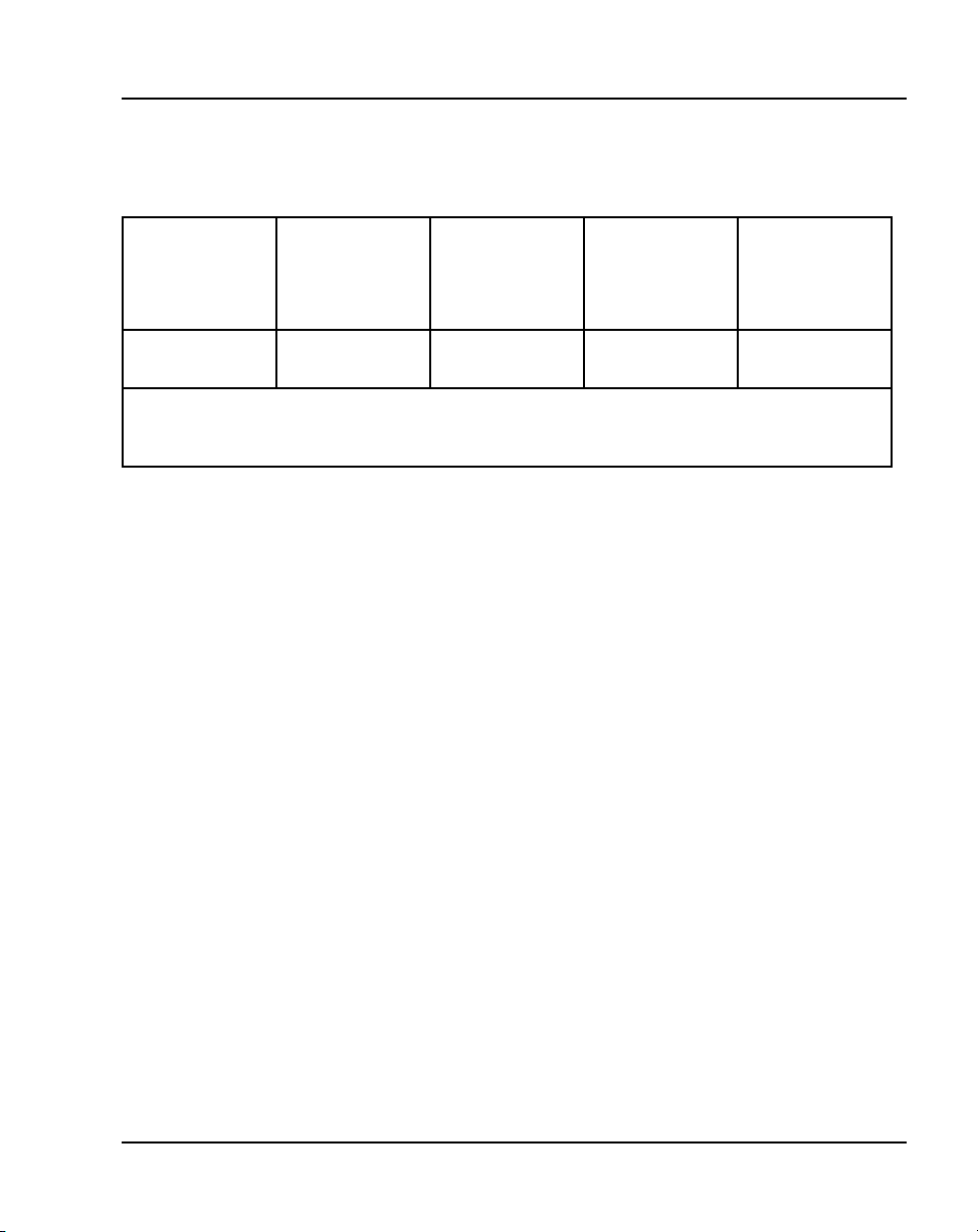
Tabl e 1
FDHF Interoperability
External
Alerter and
Recording
Interface
Functional description Page 17 of 174
Table 1 shows FDHF interoperability with other M3900 cartridges.
CTIA ATA PC Utility
FDHF YES
See Note below
Note: FDHF works with the External Alerter and Recording Interface functionality; however,
FDHF does not work with the External Alerter and Recording Interface when a recording
device is connected.
YES NO YES
To initiate Full Duplex Handsfree functionality, follow the existing steps for
Handsfree operation in the M3901, M3902, M3903, and M3904 User Guide.
System-Initiated Language Selection
With the System-Initiated Language Selection feature, the system
administrator can define a default language on a customer basis for M3902,
M3903, M3904, and M3905 sets. The default language defined by the system
administrator applies to all new M3900 sets configured for the customer
group.
When the system administrator configures a new M3900 set, the default
language is sent to the set as part of the key map download. If necessary, the
system administrator can override the system default.
Note: If the system administrator overrides the system default, it only
affects the language on the set; it does not affect the system default.
If the user changes the default language for their set, the new language
selection is uploaded to the Meridian 1 system. The new language selection
overrides the language configured for the Terminal Number (TN).
This functionality allows Virtual Office workers to store their language
selection on the Meridian 1 system. When the virtual worker logs in to a host
set, the language selection changes to the language defined for the virtual
worker.
M3900 Series Meridian Digital Telephones Description, Installation and Administration
Page 18

Page 18 of 174 Functional description
Call Forward Enhancement for M3900 sets
The Call Forward Enhancement feature modifies the method for activating
Call Forward on M3903, M3904, and M3905 sets.
To forward your calls or change the previously stored Call Forward number,
perform the following steps:
1 Press the Forward key.
The previously stored Call Forward number appears, if one exists.
2 If you want to keep the previously stored Call Forward number, press
Done.
If you want to enter a new Call Forward number, go to Step 3.
3 Enter the new Call Forward number.
When you start to enter the new number, the initial Call Forward number
automatically deletes.
Note 1: You can use the Delete key to delete each digit in the Call
Forward number shown. To edit the number, use the Left or Right
Navigation keys to move the cursor.
Note 2: A Cancel key also appears. Press the Cancel key to exit without
changing the previously stored Call Forward number.
4 Press Done.
31-Digit Dialing
With the 31-Digit Dialing feature, M3900 display screens accommodate
dialing strings of up to 31 digits. This allows the screens to fully display long
dialing strings, such as Calling Card numbers and access codes.
The M3902 set has a one-line display. Use the Left/Right Navigation keys to
scroll through the digits on the line.
M3903, M3904, and M3905 display screens accommodate 24 characters on
each line. For dialing strings greater than 24 characters, the number
automatically wraps to the second line.
553-3001-216 Standard 5.00 January 2002
Page 19
Functional description Page 19 of 174
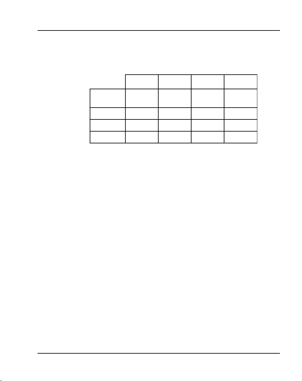
Table 2 lists the features that support 31-Digit Dialing on M3902, M3903,
M3904, and M3905 sets.
Tabl e 2
Features that support 31-Digit Dialing
M3902 M3903 M3904 M3905
Personal
Directory
Call Log X X X
Redial X X X
Predial X X X X
Context Sensitive Soft Keys
The four keys immediately below the display on the M3903, M3904, and
M3905 telephones are referred to as Soft Keys. The function or features
accessed by these keys varies depending on:
• the features configured for the telephone
• whether the phone is on-hook, off-hook, or on a call
• whether the Options List, Directory/Log, or Applications are in use
With Context Sensitive Soft Keys, only the features that are applicable and
configured for your telephone appear on the soft labels above these keys.
For example, while you are on a call, you may have access, via the Soft Keys,
to features such as Transfer and Conference. You will not, however, have
access to Forward since you do not forward your telephone while on a call.
XX
The following features can be accessed through the Context Sensitive Soft
Keys:
• Call Log (Callers List)
• Call Log (Redial List)
• Call Transfer (TRN)
• 6 Party Conference (AO6)/3 Party Conference (AO3)
M3900 Series Meridian Digital Telephones Description, Installation and Administration
Page 20

Page 20 of 174 Functional description
• Call Forward (CFW)
•RingAgain(RGA)
• Call P ark (PRK)
• Ringing Number Pickup (RNP)
• Speed Call (SCU/SCC/SSU/SSC)
• Privacy Release (PRS)
• Charge Account (CHG)
• Calling Party Number (CPN)
Callers List
M3900 Phase III introduces a Callers List soft key for M3903, M3904, and
M3905 sets. Press either the soft key or the programmable feature key to go
directly to the new callers in the list.
Note: If there are no new callers in your Callers List, when you press the
Callers List soft key or programmable feature key, you go directly to the
old Callers List.
The default soft key assignment for the Callers List is 27. However, if the
system administrator configures a Callers List programmable feature key, the
Callers List soft key is automatically removed. If necessary, the system
administrator can add the soft key back on the predefined soft key number.
Password protection applies to One-Button Feature Access to the Callers List.
If the password is enabled, when you press the Callers List soft key, a prompt
appears requesting password entry. Once you enter the correct password, you
can access the “new” Callers List.
Redial List
M3900 Phase III introduces a Redial soft key for M3903, M3904, and M3905
sets. Press either the soft key or the programmable feature key to go directly
to the Redial List.
The default soft key assignment for the Redial List is 28. However, if the
system administrator configures a Redial List programmable feature key, the
Redial List soft key is automatically removed. If necessary, the system
administrator can add the soft key back on the predefined soft key number.
553-3001-216 Standard 5.00 January 2002
Page 21
Password protection applies to One-Button Feature Access to the Redial List.
If the password is enabled, when you press the Redial List soft key, a prompt
appears requesting password entry. Once you enter the correct password, you
can access the Redial List.
Pause in Dialing String
With M3900 Phase III, M3902, M3903, M3904, and M3905 sets support a
pause in dialing. This pause is often required when a user dials remote
devices, such as answering machines, Interactive Voice Response (IVR)
systems, auto attendants, and tandem switches.
The Pause feature enters a 1.5-second delay in a dialing sequence. The user
can add the delay while programming or editing an entry in the Personal
Directory, Callers List, Redial List, and Predial List.
This feature introduces a Pause soft key. To enter a Pause in the dialing string
while editing a number, press the Pause soft key. A Pause place marker
appears in the dialing string. The place marker appears as two parallel bars,
and takes up one space in the dialing string.
Note: You can enter multiple pauses for longer delays.
Figure 1
Example of the Pause place marker in a dialing string
Functional description Page 21 of 174
5065512233*70
553-A0102
M3900 Series Meridian Digital Telephones Description, Installation and Administration
Page 22

Page 22 of 174 Functional description
Special Character Support
With M3900 Phase III, M3902, M3903, M3904, and M3905 sets support all
special characters found on a PC keyboard. Special character support allows
a user to input special characters when using the edit mode in the Personal
Directory and Set-to-Set Messaging. For example, a user can enter a name
with an accent in their Personal Directory (for example, Josée).
Special Character Support also supports “Change feature key labels” in the
Options menu.
The special character set includes all characters from the extended portion of
the ASCII character set. The extended ASCII character set that supports the
set’s current language is the character set appears in the edit mode. The
special character set contains up to 130 characters. It is displayed in six lines
with 24 characters on each line. Use the navigation keys to scroll through the
list or to move through an individual 24-character line.
The special character set does not include upper- and lower-case letters or
numerals. Use the keypad of the set to define these characters.
M3900 Headset State Support
The M3903, M3904, and M3905 sets support the use of a headset. With
M3900 Phase III, for the headset to operate, the system administrator no
longer has to set the Class of Service to Handsfree Allowed (HFA) in LD 11.
Set-to-Set Messaging
The Set-to-Set Messaging feature provides a visual message from one M3900
telephone to another M3900 telephone when a user makes a call to that
telephone. The user on an M3903, M3904, or M3905 set enters the Set-to-Set
message text at the telephone. Set-to-Set Messaging is accessed through the
Applications Key.
The maximum length for Set-to-Set message text is 24 characters (one line of
the set display).
553-3001-216 Standard 5.00 January 2002
Page 23

Functional description Page 23 of 174
Table 3
Sample of Message Text
OUT TO LUNCH
BACK TO WORK: 4 Dec 99
BACK TO OFFICE: Jan 00
WILL REPLY AFTER 1 PM
BACK @ 4:00 PM
NOT IN TODAY
RETURN SOON -- 8:10 AM
GONE FOR THE DAY
The user can have only one Set-to-Set message on their telephone at a time.
To activate Set-to-Set Messaging, the user must first define a message. If
password protection is active for the M3900, it also applies to Set-to-Set
Messaging.
If the Multiple Appearance Redirection Prime (MARP) feature is active, then
MARP determines which DNs receive the Set-to-Set message. If MARP is
not active, then Multiple Appearance Directory Number (MADN) determines
which DNs configured on the telephone receive the Set-to-Set message.
To use Set-to-Set Messaging the M3903 or M3904 telephone must have:
• the Set-to-Set feature Class of Service enabled in LD 11
• a Set-to-Set message text created
• the Set-to-Set Messaging feature enabled
When Set-to-Set Messaging is active, the caller hears an audible tone and the
Set-to-Set Message appears on their display. The caller then hears ringback
and the call goes to voice messaging. If the called set is busy, a call waiting
tone is heard by the called party.
M3900 Series Meridian Digital Telephones Description, Installation and Administration
Page 24

Page 24 of 174 Functional description
Set-to-Set Messaging Enhancements for Phase III sets allow the system
administrator to predefine ten messages for the M3903, M3904, and M3905
sets. The telephone user can select one of the messages as their set-to-set
message. The telephone user can also edit a message before selecting it as
their set-to-set message.
When the system administrator chooses the system-initiated language for the
M3900 sets, the list of ten predefined set-to-set messages for that language is
loaded into memory from the hard disk.
When the predefined messages are in memory, the system administrator can
customize them for a particular customer group.
Note: Each customer group on the Meridian 1 system can have its own
default language and list of predefined set-to-set messages for its end
users.
When a set has Set-to-Set Messaging Allowed (STSA) Class of Service
defined, the user can select and edit any of the ten messages listed in Table 3.
However, only one of the messages is stored as the user’s set-to-set message.
The user presses the Up and Down navigation keys to scroll through the list
of predefined messages. When scrolling down, the list wraps from message
ten to message one. When scrolling up, the list wraps from message one to
message ten.
Tabl e 4
Predefined set-to-set messages
Message # Message
1 Please leave message
2 Backtowork
3 In a meeting
4 On a conference call
5Atlunch
6 Busy, call
553-3001-216 Standard 5.00 January 2002
Page 25
Functional description Page 25 of 174
Message # Message
7 Out of the office today
8 On a business trip
9 Project deadline today
10 Will reply after
With M3900 Phase III, the Set-to-Set Messaging screen has three soft keys.
The ON/OFF key toggles the Set-to-Set Messaging feature on or off. The
ON/OFF key only appears if the currently displayed message is saved. The
Edit key allows the user to customize the message displayed on the screen.
The Select soft key appears only if the currently displayed message is not
saved. When pressed, this soft key selects the currently displayed message as
the set-to-set message to be stored.
Set-to-Set Messaging Enhancements introduces a Message (Msg) field. This
field contains either the number of the displayed message or the word
“Saved”. The system saves only one message. A message is saved when the
user does one of the following:
• highlights a message and then presses Select
• edits a message and then presses Done
Note: When the user performs one of the above, the new message
overrides any previously saved messages.
When the user edits a message, the modified message is displayed when the
user scrolls through the list. However, if the user then edits another message,
that message replaces the previously modified message.
One-Button Feature Access to Corporate Directory
With One-Button Feature Access, users have more direct access to the
Corporate Directory.
M3900 Series Meridian Digital Telephones Description, Installation and Administration
Page 26

Page 26 of 174 Functional description
Press the Applications key to access the corporate Directory on M3903,
M3904, and M3905 sets. With M3900 Phase III, you do not have to press the
Select key after pressing the Applications key. Once you press the
Applications key, you can immediately begin a search using the dial pad keys,
provided that Corporate Directory was highlighted in the Applications
selection list.
Corporate Directory Search Enhancement
With M3900 Phase III, the Corporate Directory Search Enhancement
introduces the Resume soft key to the Corporate Directory screens of the
M3903, M3904, and M3905 sets. The Resume key allows you to return to the
Corporate Directory Find screen to enter additional characters and to continue
your search without starting over from the beginning.
The Resume key appears on the following Corporate Directory screens:
• List view
•Cardview
• No matches found
When you press the Resume soft key, the Corporate Directory Find screen
returns with the information that you previously entered. The cursor is placed
after the last letter that you entered. You can enter additional letters and then
press the Done soft key. This brings you to a new point in the directory.
The M3903, M3904, and M3905 telephones provide access from the
telephone to a corporate wide directory. The Corporate Directory is accessed
through the Applications Key. The Corporate Directory allows:
• users to search by name
• a user to view additional information on each entry
• the user to dial from the Corporate Directory
• the user to copy and paste an entry into the Personal Directory (M3904
and M3905)
553-3001-216 Standard 5.00 January 2002
Page 27

Functional description Page 27 of 174
• an alphabetical listing of entries by using the last names (system
generated)
Note: When names are copied to the Personal Directory (M3904 and
M3905), the names are listed by first name.
• the system administrator to configure Meridian Administration Tools
(MAT) to download the directory database manually or automatically to
the system
Operating parameters for the Corporate Directory
The user must have an M3903, M3904, or M3905 telephone to support the
Corporate Directory feature. To access the Corporate Directory from the
telephone, the user must have the Corporate Directory Class of Service
enabled.
When the Corporate Directory is being updated with new data, the user
cannot access the Corporate Directory. The user exits the Corporate Directory
by pressing the Quit Key or the Applications Key.
The MAT or Optivity Telephony Manager (OTM) Corporate Directory utility
gathers data from the MAT or OTM databases and downloads it to the
Meridian 1 system. To use the Corporate Directory utility, MAT 6.6 or
OTM 1.0 or later must be installed. For Release 25.40, OTM must be used.
Virtual Office
The Virtual Office feature allows users to log in to a designated M3903 or
M3904 telephone and use their individual telephone configurations at that
telephone. The calls to the user’s primary DN are routed to the Virtual Office
Host Terminal where the Virtual Office Worker is logged in.
The Host Terminal is the physical telephone that a user can use to log in as a
Virtual Office worker. Both the M3903 and M3904 can be configured as Host
Terminals; however, a Virtual Office Worker is required to login to a Host
Terminal that matches their Virtual Terminal set type. For example, when the
Virtual Terminal of a Virtual Office Worker is configured as an M3904, the
login process is blocked if they attempt to login to an M3903 Host Terminal.
The Virtual Terminal is a set of features configured for a user and defined on
a phantom loop. There is no permanent physical telephone associated with a
Virtual Terminal.
M3900 Series Meridian Digital Telephones Description, Installation and Administration
Page 28

Page 28 of 174 Functional description
The Virtual Office recognizes all system configuration related to the Virtual
Office Worker. The Virtual Office feature operates on stand-alone
Meridian 1 systems only.
Only one active session per user login ID is allowed at one time in the system.
The Virtual Office Worker is identified by their primary DN, which cannot
be used as the primary DN for any other set, virtual or physical, in the system.
Use the Station Control Password (SCPW, configured in overlay 11), to
validate the login.
Nortel Networks recommends that the Host Terminal have at least internal
call and emergency call (911 in North America) capability.
Clearing of the Directory Services Password
With M3900 Phase III, the Meridian 1 system clears the Directory Services
password when a virtual office worker logs in or out of an M3903 or M3904
Host set. The system administrator configures this functionality by defining
Class of Service as Erase List Allowed (ELA) in Overlay 11 for the M3903
or M3904 Virtual set.
This Clearing of Password functionality allows multiple virtual workers,
using the same host set, to have access to password-protected features if one
of the users sets the password and does not turn it off when they log out.
Clearing of the Callers List and Redial List
With M3900 Phase III, the Meridian 1 system clears the Redial and Callers
lists when a virtual office worker logs in or out of an M3903 or M3904 Host
set. The system administrator configures this functionality by defining Class
of Service as Erase List Allowed (ELA) in Overlay 11 for the M3903 or
M3904 Virtual set. When the ELA Class of Service is defined, the Callers List
and Redial List are automatically cleared when the virtual worker logs in or
out.
553-3001-216 Standard 5.00 January 2002
Page 29

Functional description Page 29 of 174
Automatic Logout for Virtual Office
M3900 Phase III introduces automatic logout for virtual workers. If a virtual
worker, who is already logged on to Set A, tries to log on to Set B, the system
automatically logs the virtual worker off Set A and logs them on to Set B
(provided that the virtual worker enters the correct login password). The
system administrator enables this functionality in Overlay 15 at the Virtual
Office Automatic Logout (VO_ALO) prompt.
The system administrator can also define a time at which all virtual terminals
are automatically logged out. The system administrator configures the
automatic logout time at the Virtual Office Automatic Logout Time
(VO_ALOHR) prompt in Overlay 15.
If the set is busy at the automatic logout time (for example, if the virtual
worker is using Corporate Directory or Set-to-Set Messaging), it is not logged
out until it becomes idle.
Note: If a user logs in to a virtual set after automatic logout, the set does
not automatically log out a second time.
SpeedCallforVirtualOffice
With M3900 Phase III, M3900 sets support Speed Call (SCU/SCC) and
System Speed Call (SSU only) on Virtual Terminal Numbers.
Operating parameters for Virtual office
The Virtual Terminal Prime DN cannot be a Primary DN on another terminal.
The Virtual Terminal Prime DN (user A) can be the secondary DN of another
Virtual Terminal (user B).
If both user A and user B are logged in, a call to user A’s Primary DN can be
answered by user B’s Secondary DN.
If virtual user A logs out, user B logs in, and a user calls the Primary DN of
set A, the scenarios are as follows:
• If user A has Call Forward configured before logout, the call is
forwarded.
M3900 Series Meridian Digital Telephones Description, Installation and Administration
Page 30

Page 30 of 174 Functional description
• If user A does not have Call Forward configured, but has the default Call
Forward (DCFW) configured, the call is forwarded to that DN (the DN
can be Meridian Mail).
• If neither of the above two scenarios apply, the caller receives overflow
tone.
Display-based Expansion Module
The Display-based Expansion Module is an accessory that provides a single
strip of eight additional keys for the M3904 and M3905 telephones. The user
presses the Page Key on the Display-based Expansion Module to access three
different layers of keys. A single Display-based Expansion Module can be
configured to provide up to 24 soft-labeled programmable feature or DN keys
(eight keys on each of the three layers).
Flash Download
Flash Download provides the ability to download a new version of firmware
from the Meridian 1 to a single M3900 Series telephone, or to a range of
M3900 Series telephones. For X11 Release 25, this feature is applicable to
M3902, M3903, M3904, and M3905 telephones. Flash Download enables
firmware upgrades without the necessity of replacing the telephones in the
field, thereby “future-proofing” the M3900 Series telephones.
System-Initiated Language Download
For the initial system-initiated language download, if the system
administrator chooses a language that is not supported by one of the sets, the
language selection remains at the default (English). When the system
administrator chooses an unsupported language, an error message appears on
the TTY.
Set-to-Set Messaging
If the system administrator chooses a language and the file containing the ten
predefined messages for that language cannot be found on the hard disk, the
list of messages stored in memory will be completely blank. The system
administrator can still create a list of customized messages in the same
manner as if they were only modifying one or two of the predefined
messages.
553-3001-216 Standard 5.00 January 2002
Page 31

Functional description Page 31 of 174
When the administrator enters Yes at the STS_MSG prompt in overlay 15, the
prompt MSG xx appears (Where xx=01~ 10) and this predefined default
message will not be printed out in overlay 15. The administrator can update
the message or press the Enter key to accept the default message. The
administrator can print out the messages in overlay 21 after the changes are
made in overlay 15. A message can be deleted by typing X and pressing the
<CR> key. This piece of message then becomes empty.
Language selection during software installation
With X11 Release 25, the software installer has been given the ability to
select one of the following language sets to be installed on the Meridian 1.
This selection determines the languages available to M3900 Series telephone
users.
• Global 10 Languages (Release 3)
Swedish, Italian, Norwegian, Brazilian Portuguese, Finnish, Japanese
Katakana
• Western Europe 10 Languages (Release 3)
Spanish, Swedish, Norwegian, Danish, Finnish, Italian, Brazilian
Portuguese
• Eastern Europe 10 Languages (Release 3)
Dutch, Polish, Czech, Hungarian, Russian, Latvian, Turkish
• North America 6 Languages (Release 3)
Spanish, Brazilian Portuguese, Japanese Katakana
• Spare Group A
• Spare Group B
During the software installation process, the installer selects one of the above
Peripheral Software DownLoad (PSDL) files. Please see Software
Conversion Procedures (553-2001-320) for information on software
installation.
General features
The specific characteristic of the five models of the M3900 Series telephones
is found on the following pages. Refer to:
English, French, German, Spanish,
English, French, German,
English, French, German,
English, French, German,
• “M3901” on page 36
M3900 Series Meridian Digital Telephones Description, Installation and Administration
Page 32

Page 32 of 174 Functional description
• “M3902” on page 37
• “M3903” on page 39
• “M3904” on page 41
• “M3905” on page 43
The M3900 Series Meridian Digital Telephones support features through:
• Fixed Feature Keys
• Programmable Line/Feature Keys (self-labeled)
• Programmable Soft Keys (self-labeled) (M3902 and M3905)
• Context Sensitive Soft Keys (M3903, M3904, and M3905)
• Applications Key
— Set-to-Set Messaging (M3903, M3904, and M3905)
— Corporate Directory (M3903, M3904, and M3905)
• M3900 “Hardware options” on page 45
Feature keys
Personal Directory
With M3900 Phase III, press the Directory/Log fixed feature key to access the
Personal Directory on M3904 sets. On M3905 sets, press the Directory
self-labelled programmable feature key. You do not have to press the Select
key after pressing the Directory/Log or DIR/LOG key. Once you press the
Directory/Log or DIR/LOG key, you can immediately begin a search using
the dial pad keys, provided that Personal Directory was highlighted in the
selection list.
Note: M3900 Phase III allows you to perform a three-letter search in the
Personal Directory.
553-3001-216 Standard 5.00 January 2002
Page 33

The Fixed Feature Keys (see Table 5) are the feature keys on the M3900
Fx
Series Meridian Digital Telephone that are prelabeled with the assigned
feature. The Fixed Feature Keys appear on the telephone with text or icon
labels. Telephones with icon labels are only available in specific market
areas.
Tabl e 5
Fixed Feature Key text and icon labels (Part 1 of 3)
Feature Text Key Label Icon Key Label
Functional description Page 33 of 174
Goodbye
Hold
Mute
Handsfree
Volume
Headset
Options
DN line
Feature (M3901)
Message
Goodbye
or
Hold
Mute
Headset
Options
Line
Feature
Message
Directory/Log (M3904)
Directory/Log
M3900 Series Meridian Digital Telephones Description, Installation and Administration
Page 34

Page 34 of 174 Functional description
Tabl e 5
Fixed Feature Key text and icon labels (Part 2 of 3)
Feature Text Key Label Icon Key Label
Call Log (M3903)
Shift
Application
Navigation
Copy
Quit
Transfer
(M3902)
InCalls
(M3905 Call Center)
Not Ready
(M3905 Call Center)
Make Busy
(M3905 Call Center)
Call Log
Shift
Applications
Copy
Quit Quit
Transfer
In - Calls
Not Ready
Make Busy
Call Supervisor
(M3905 Call Center)
Answer Agent
(M3905 Call Center)
Supervisor
Ans Agent
Activity Code
(M3905 Call Center)
Answer Emergency
(M3905 Call Center)
Ans Emerg
553-3001-216 Standard 5.00 January 2002
Activity
Page 35

Tabl e 5
Fixed Feature Key text and icon labels (Part 3 of 3)
Feature Text Key Label Icon Key Label
Functional description Page 35 of 174
Emergency
(M3905 Call Center)
Observe Agent
(M3905 Call Center)
Display Queue
(M3905 Call Center)
Note: Icon key labels are available in specific markets areas.
Emergency
Obv Agent
Dsply Queue
Programmable Line/Feature Keys (self-labeled)
The Programmable Line/Feature Keys (self-labeled) are the keys located at
the left and right sides of the upper section of the display area. The user can
change the LCD label of these keys (with the exception of the primary
Directory Number Key) to meet their business needs.
The Programmable Line/Feature Key (self-labeled) provides two layers of
functionality on the M3903 and M3904. The two layer keys on the M3903
and M3904 provides the user access to two Lines/Features per key. For
example, the M3904 has six Programmable Line/Feature Keys (self-labeled),
which provide the user with 12 line/feature keys accessible on the six keys.
Soft Keys (self-labeled)
The Soft Keys (self-labeled) are the three (M3902) or four (M3903, M3904,
and M3905) keys located below the display on the M3900 Series Meridian
Digital Telephones. The labels and corresponding functionality of these keys
change depending on the features available or the application in use.
Programmable Features
The M3901 can have five Programmable Features assigned. The user
activates the features by pressing the Feature Key and assigned key pad keys
as indicated by the Feature Card. The system administrator programs selected
features for the M3901 telephone.
M3900 Series Meridian Digital Telephones Description, Installation and Administration
Page 36

Page 36 of 174 Functional description
For feature key assignment information see:
• Table 8, “M3901 key description,” on page 74
• Table 9, “M3902 key description,” on page 76
• Table 10 “M3903 key description” on page 77
• Table 11 “M3904 key description” on page 80
• Table 12 “M3905 key description” on page 83
M3901 Entry Telephone
The features of the M3901 include:
• one line (Directory Number (DN)) capability
• five programmable features
• Fixed Feature Keys: Line, Feature, Hold, Goodbye, and Volume control
• Feature Activation and Message Waiting/Incoming Call Status Indicator
LED
• support for an amplified headset
Figure 2
M3901
Feature Activation Indicator
Feature
Goodbye
Line
553-3001-216 Standard 5.00 January 2002
Volume Bar
Hold
Message and Call
Status Indicator
Feature Card
553-8966
Page 37

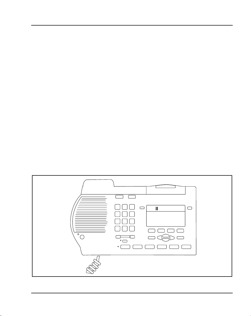
Figure 3
M3902
Functional description Page 37 of 174
M3902 Basic Telephone
The features of the M3902 include:
• one line (Directory Number (DN)) capability
• three Programmable Soft Keys (self-labeled)
• Fixed Feature Keys: Options, Message, Transfer, Goodbye, Hold,
“Smart” Mute, and Volume control
• two lines by twenty-four character display area
•GroupListening
• on-hook dialing
• support for an amplified headset
• one accessory port
• handsfree calling option with LED
LCD Indicator
Message Waiting Light
One Line
Programmable
Feature Keys
Handsfree Key
LED
Volume Bar
Navigation Keys
LED
Fixed Feature Keys
553-8624
M3900 Series Meridian Digital Telephones Description, Installation and Administration
Page 38

Page 38 of 174 Functional description
M3903 Enhanced Telephone
The features of the M3903 include:
• two Programmable Line/Feature Keys (self-labeled) which have two
layers each, giving the user access to four Line/Feature keys
• four Context Sensitive Soft Keys (self-labeled) that change functionality
depending on the features available or the application in use
• Handsfree calling with LED
• Fixed Feature Keys: Goodbye, Message, Call log (including Redial List),
Applications, Shift, Goodbye, Hold, “Smart” Mute, and volume control
• Navigation cluster, Quit, and Copy
• three line by twenty-four character display area
• Call Log (includes Redial List)
•GroupListening
• on-hook dialing
• two accessory ports
• support for an amplified or unamplified headset
• Direct Connect Headset port
553-3001-216 Standard 5.00 January 2002
Page 39

Figure 4
M3903
Functional description Page 39 of 174
LCD Indicator
Goodbye
Hold
Message Waiting Light
Soft-labeled Line/
Feature keys.
Handsfree Key
LED
Volume Bar
LED
Options
Quit
Programmable
Feature Keys
Fixed Feature Keys
Copy
Navigation Keys
553-8625
M3900 Series Meridian Digital Telephones Description, Installation and Administration
Page 40

Page 40 of 174 Functional description
M3904 Professional Telephone
The features of the M3904 telephone include:
• six Programmable Line/Feature Keys (self-labeled) which have two
layers each, giving the user access to 12 Line/Feature keys
• four Context Sensitive Soft Keys (self-labeled) that change functionality
depending on the features available or the application in use
• Handsfree Calling with LED
• Fixed Feature Keys: Options, Message, Directory/Log (including Redial
List), Applications, Shift, Goodbye, Hold, “Smart” Mute, Volume
control
• Navigation cluster, Quit, and Copy
• five line by twenty-four character display
• Personal Directory
• Call Log (includes Redial List)
•GroupListening
• on-hook dialing
• two accessory ports (support for an amplified/unamplified headset)
• Direct Connect Headset port
553-3001-216 Standard 5.00 January 2002
Page 41

Figure 5
M3904
LCD Indicator
Goodbye
Hold
Functional description Page 41 of 174
Message Waiting Light
Soft-labeled Line/
Feature Keys
LED
Handsfree Key
Volume Bar
Options
Quit
LED
Programmable
Feature Keys
Fixed Feature Keys
Copy
Navigation Keys
553-8626
M3900 Series Meridian Digital Telephones Description, Installation and Administration
Page 42

Page 42 of 174 Functional description
M3905 Call Center Telephone
The features of the M3905 Call Center Telephone include:
• eight Programmable Line/Feature Keys (self-labeled), giving the user
access to eight Line/Feature Keys
• four Context Sensitive Soft Keys (self-labeled) that change functionality
depending on the features available or the application in use
• Fixed Feature Keys with LED: Headset, Supervisor, Emergency, Not
Ready, Make Busy, In-Calls, goodbye, Hold, “Smart” Mute, Volume
control
• Navigation cluster, Quit and Copy
• four line by twenty-four character display
• an optional handset
• two accessory ports (supports amplified/unamplified headset)
• Supervisor Observe Key with LED
• Supervisor Headset Observe port
553-3001-216 Standard 5.00 January 2002
Page 43

Figure 6
M3905
LCD Display
Goodbye
Hold
Functional description Page 43 of 174
Message Waiting Light/
Incoming Call Indicator
LED
Supervisor
Observe Key
Volume Control Bar
Headset
Programmable Line/
Feature Keys
(Self-labeled)
Programmable
Feature Keys
(Self-labeled)
Fixed Feature Keys
In-Calls
Copy
LED
Mute
Supervisor
Emergency
Navigation Keys
Not Ready
Quit
Make Busy
Note: The system administrator can configure four of the bottom six
Fixed Feature Keys (Make Busy, Not Ready, Supervisor and
Emergency) to Feature Keys that suit the business needs of the Call
Center user.
553-9043
M3900 Series Meridian Digital Telephones Description, Installation and Administration
Page 44

Page 44 of 174 Functional description
553-3001-216 Standard 5.00 January 2002
Page 45

54
Page 45 of 174
Hardware options
Contents
The following are the topics in this section:
Description.. ............................................ 46
Accessory Connection Module (ACM) . .. . . . . . . . . . . . . . . . . . . . . . . 47
AlternatekeycapsfortheM3905............................. 48
AnalogTerminalAdapter(ATA)............................. 49
ComputerTelephonyIntegrationAdapter(CTIA)................ 49
Telephone Application Programming Interface
(TAPI)software........................................... 49
Personal Directory PC Utility Software . . . . . . . . . . . . . . . . . . . . . . . . 50
Personal Directory PC Utility . . . . . . . . . . . . . . . . . . . . . . . . . . . . . . . . 50
ExpansionModules........................................ 51
Display-basedExpansionModule.......................... 51
Key-basedExpansionModule............................. 51
ExternalAlerterandRecordingInterface....................... 51
Handset option for the M3905 Call Center Telephone . . . . . . . . . . . . . 52
Headsetoptions........................................... 52
TelephoneWallMountKit.................................. 52
FullDuplexHandsfree.. ................................... 52
M3900 Series Meridian Digital Telephones Description, Installation and Administration
Page 46

Page 46 of 174 Hardware options
Description
Table 6 lists the features and optional hardware available for each M3900
series telephone.
Tabl e 6
M3900 Series telephone accessories compatibility (Part 1 of 2)
Accessory
Accessory
Connection
Module (ACM)
Analog Terminal
Adapter (ATA)
Computer
Telephony
Integration
Adapter (CTIA)
Display-based
Expansion Module
(DBA)
Key-based
Expansion Module
External Alerter
and Recording
Interface
Full Duplex
Handsfree
PersonalDirectory
PC Utility
X11
release
introduced
Release
24.24
Release
25.40
Release
25.10
Release
24.24
Release
24.24
Release
25.40
Release
24.24
M3900
phase
introduced
Phase I Supports Supports Supports Supports
Phase 3 Supports Supports Supports Supports
Phase 2 NA NA Supports Supports
Phase 1 NA Supports Supports NA
Phase 1 Supports Supports Supports Supports
Phase 3 Supports NA NA NA
Phase 1 Supports Supports
M3902 M3903 M3904 M3905
NA Supports Supports Supports
1
NA NA
1
1
Headset
(non-amplified)
connects thought
he direct connect
headset jack
553-3001-216 Standard 5.00 January 2002
NA NA Supports Supports
Page 47

Hardware options Page 47 of 174
Tabl e 6
M3900 Series telephone accessories compatibility (Part 2 of 2)
X11
Accessory
Headset
(amplified)
connects through
the headset jack
Handset Standard Standard Standard Standard
Note 1: M3905 Phase III firmware and X11 Release 25.40 or later software are required to support the
Personal Directory PC Utility, DBA, and CTIA accessories.
release
introduced
M3900
phase
introduced
M3902 M3903 M3904 M3905
Supports Supports Supports Supports
Accessory Connection Module (ACM)
The Accessory Connection Module provides the interface for adding the
Analog Terminal Adapter, External Alerter and Recorder Interface,
Computer Telephony Integration Adapter, and Personal Directory PC Utility.
The ACM is available for the M3902, M3903, M3904 and the M3905. The
ACM requires a wall transformer to power any of the accessory cartridges.
You must order the wall transformer separately from your Nortel Networks
distributor to power the ACM and/or the M3900 accessories.
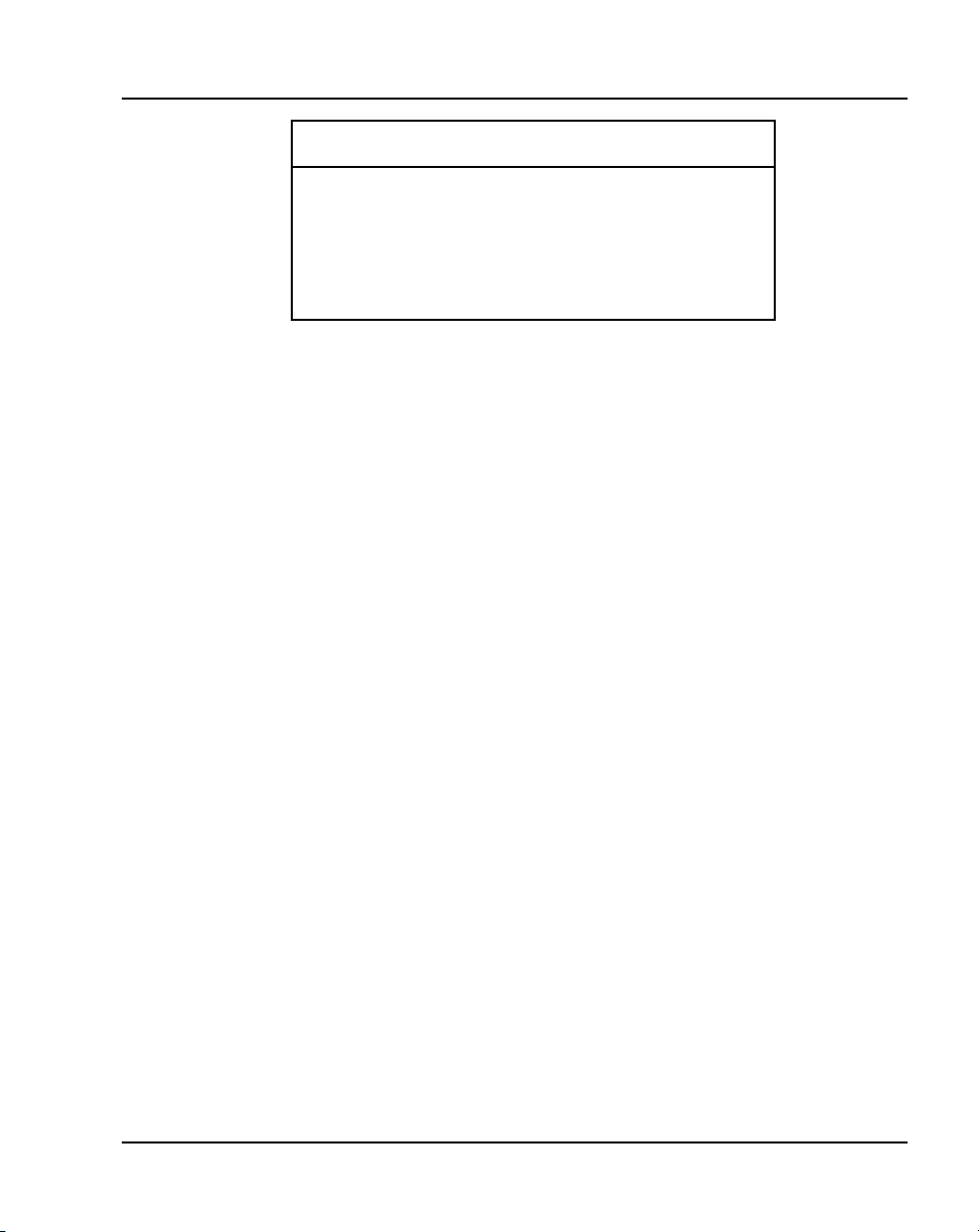
Tabl e 7
Accessory compatibility (Part 1 of 2)
Analog
Term i n a l
Adaptor
(ATA)
Key
Expansion
Module (2)
Personal
Key-based
Expansion
ATA
NA YES YES YES YES YES
YES NA YES YES NO YES
M3900 Series Meridian Digital Telephones Description, Installation and Administration
Module
Directory
PC
Utility
External
Alerter and
Recording
Interface
Display-
based
Expansion
Module
CTIA
Page 48

Page 48 of 174 Hardware options
Tabl e 7
Accessory compatibility (Part 2 of 2)
Personal
Key-based
Expansion
ATA
Personal
Directory
PC Utility
External
Alerter and
Recording
Interface
Display
Expansion
Module (1)
Computer
Telephony
Integration
Adapter
(CTIA)
Full Duplex
Handsfree
Note: Not all of the above accessories are supported on all telephones in the M3900 Series
portfolio.
YES YES NA YES YES YES
YES YES YES NA YES YES
YES NO YES YES NA YES
YES YES YES YES YES NA
YES NA YES YES NA YES
Module
Directory
PC
Utility
External
Alerter and
Recording
Interface
Display-
based
Expansion
Module
CTIA
Alternate key caps for the M3905
The M3905 Call Center Telephone provides an alternate key cap kit to
customize your M3905 telephone to fit your business needs. Use the Key Cap
Tool to remove any of the middle four fixed programmable keys, located at
bottom front of the M3905, and replace them with alternate keys. The
alternate key caps include: Answer Emergency, Answer Agent, Activity
Code, Call Agent, Observe Agent, and Display Queue.
553-3001-216 Standard 5.00 January 2002
Page 49

Hardware options Page 49 of 174
Analog Terminal Adapter (ATA)
The Analog Terminal Adapter (ATA) lets you connect an analog device such
as a fax machine or modem to your telephone. You can have simultaneous use
of the telephone and the analog device. The ATA is available for the M3902,
M3903, M3904 and the M3905 models.
Computer Telephony Integration Adapter (CTIA)
The Computer Telephony Integration Adapter (CTIA) along with the TAPI
software provides an interface to connect a Personal Computer (PC) to the
M3900 telephone.
An RS-232C cable is required to connect the PC to the CTIA. The CTIA
connects to the M3900 Series telephone through the Accessory Connection
Module (ACM). The CTIA is a small cartridge accessory and can be inserted
into either the small or large footstand opening.
The CTIA is powered through the ACM. The ACM receives power through
the telephone via the telephone line cord which is connected to a Teladapt
wall transformer power supply (see Figure 13 on page 93). Check with your
Nortel Networks distributor for the recommended wall transformer for the
M3900 accessories. Install the Accessory Connection Module (ACM) into
your M3900 Series Meridian Digital Telephone (refer to the ACM
Installation Sheet) before you install your CTIA.
The CTIA cartridge provides the user:
• connectivity to the PC
• voice call control
Telephone Application Programming Interface (TAPI) software
TAPI software accompanies your CTIA Cartridge. The TAPI software allows
a user to program telephone-line-based devices to work independently from
their computer or other devices.
M3900 Series Meridian Digital Telephones Description, Installation and Administration
Page 50

Page 50 of 174 Hardware options
Personal Directory PC Utility Software
In addition to the TAPI software which is included with the CTIA, you may
wish to purchase the Personal Directory PC Utility Software. The Personal
Directory PC Utility software uses your CTIA Cartridge to connect your PC
and M3904 telephone so that you may exchange data between your PC and
your telephone’s directory. For more information see Personal Directory PC
Utility.
Personal Directory PC Utility
The Personal Directory PC Utility software provides a faster, easier way to
create or modify a Personal Directory on the M3904 and M3905 telephones.
You can enter names and numbers into a Personal Directory file on your
Personal Computer (PC). You can download (program) the PC file directly to
the M3904 and M3905 telephones. You can upload (read) a directory from
the M3904 and M3905 telephones to your PC to modify the directory.
An RS-232C cable is required to connect the PC to the Personal Directory PC
Utility Interface Cartridge. The cartridge connects to the M3900 Series
telephone through the Accessory Connection Module (ACM). The Personal
Directory PC Utility Interface Cartridge is a small cartridge accessory and can
be inserted into either the small or large footstand opening.
The Personal Directory PC Utility Interface Cartridge is powered through the
ACM. The ACM receives power through the telephone via the telephone line
cord which is connected to a Teladapt wall transformer power supply (see
Figure 13 on page 93). Check with your Nortel Networks distributor for the
recommended wall transformer for the M3900 accessories. You must install
the Accessory Connection Module (ACM) into your M3900 Series Meridian
Digital Telephone (refer to the ACM Installation Sheet) before you install
your Personal Directory PC Utility Interface Cartridge.
Note: The CTIA Cartridge and the Personal Directory PC Utility
Interface Cartridge are identical.
The Personal Directory PC Utility supports the following languages: English,
French, Spanish, German, Danish, Portuguese, Italian, Norwegian, Swedish,
Finnish, Dutch. The default language is English.
553-3001-216 Standard 5.00 January 2002
Page 51

Expansion Modules
Display-based Expansion Module
The Display-based Expansion Module (DBA) provides additional
Line/Programmable Feature Keys (Self-labeled) for the M3904 and M3905.
The DBA supports up to three layers of eight additional keys for a total of 24
keys.
Note: Refer to Table 7 on page 47 for a list of the telephones with which
the Display-based Expansion module is compatible.
A Page fixed key located on the DBA allows a user to switch between the
three layers of Self-labeled Programmable Feature Keys. Visual indication is
also provided to indicate which page (or layer) of Self-labeled Programmable
Feature Keys is in use. Feature activation and deactivation on the DBA Keys
is the same as the Programmable Feature Keys on the M3904 and M3905.
The user may change the feature key labels by selecting “Change feature key
label” from the Options List on the M3904 or M3905.
The Display-based Expansion Module is only supported on the M3904 and
M3905. You can attach a maximum of one Display-based Expansion Module
to an M3904 or M3905 set.
Hardware options Page 51 of 174
Key-based Expansion Module
The Key-based Expansion Module (KBA) attaches to the M3904 and M3905
Meridian Digital Telephones. The KBA provides 22 additional Line/Feature
Keys. You can attach a maximum of two Key-based Expansion Modules to
the M3904 and M3905.
External Alerter and Recording Interface
The External Alerter and Recording Interface provides an interface for a
remote ringer device installed in a location separate from the telephone. The
External Alerter and Recording Interface provides access to a standard,
off-the-shelf remote ringer, call status relay, audio recorder or visual
indicator.
You can program the External Alerter interface to activate a ringer (or light)
when the telephone rings or when the telephone is in use (off hook).
M3900 Series Meridian Digital Telephones Description, Installation and Administration
Page 52

Page 52 of 174 Hardware options
Note: The External Alerter is an interface only, the ringer, light, buzzer
etc. is available through a third party vendor.
Handset option for the M3905 Call Center Telephone
The Handset does not accompany the M3905 Call Center Telephone. The
Handset kit is a hardware option for the M3905 Call Center Telephone. The
handset can be added to the M3905 by removing the front plate of the
telephone. A handset kit is available for the M3905.
Headset options
The M3901, M3902, M3904, and M3905 supports an amplified headset when
the headset connects to the handset jack.
The M3903, M3904 and M3905 have a dedicated headset jack which
supports a non-amplified headset. The M3903, M3904 and M3905 have a
Headset Fixed Feature Key to turn the Headset on and off.
Contact your Nortel Networks distributor for recommended headset
equipment.
Telephone Wall Mount Kit
The telephone wall mount bracket kit contains a one piece wall mount plate
that attaches the M3903, M3904 and M3905 telephone to the wall. The Wall
Mount Kit is available from your local Nortel Networks distributor. The
M3901 and M3902 have built in wall mount brackets.
Full Duplex Handsfree
The Full Duplex Handsfree (FDHF) functionality allows simultaneous
two-way communication during a handsfree call. For Full Duplex Handsfree
functionality, you require an M3904 Phase III set equipped with an FDHF
cartridge.
The FDHF functionality requires the following hardware:
• M3904 Phase III set (NTMN34GA)
Note: NTMN34TA is the M3904 Phase III Icon set.
• Full Duplex Handsfree cartridge (NTMN72AA)
553-3001-216 Standard 5.00 January 2002
Page 53

Hardware options Page 53 of 174
• Accessory Connection Module (ACM) (NTMN71AA)
• One of the following wall transformers to power the FDHF cartridge:
—110V wall transfer (NTMN80AA)
—220V wall transformer (NTMN80BA)
—EU 230V wall transformer (NTHC08AA)
—UK230Vwalltransformer(NTHC09AA)
M3900 Series Meridian Digital Telephones Description, Installation and Administration
Page 54

Page 54 of 174 Hardware options
553-3001-216 Standard 5.00 January 2002
Page 55

86
Page 55 of 174
Configure the M3900 Series Meridian Digital Telephone
Contents
The following are the topics in this section:
Referencelist............................................. 57
Configure the M3901, M3902, M3903, M3904,
andM3905telephone.................................... 60
Tasksummarylist....................................... 60
Configure for Corporate Directory and Set-to-Set Messaging . .. . . 65
To clear or reset a Directory Password for
theM3900Seriestelephone............................... 66
Configure the Virtual Office Flexible Feature Codes . . . . . . . . . . . 67
PrintalistorcountofVirtualOfficetelephones............... 68
ConfiguretheVirtualOfficePhantomloop................... 68
PrintdataforVirtualandHostTerminals.. .................. 69
Print M3900 firmware versions found on the system disk . .. . . . . . 69
Configure parameters for System-wide Flash Download . . . . . . . . 70
Configure parameters for the Full Duplex Handsfree (FDHF)
functionality........................................... 72
Commands in LD 32 to support the Flash Download feature . . . . . 73
M3900Serieskeydescriptions............................... 74
M3901keydescriptions.................................. 74
M3902keydescriptions.................................. 76
M3903keydescriptions.................................. 77
M3904keydescriptions.................................. 80
M3905keydescriptions.................................. 83
M3900 Series Meridian Digital Telephones Description, Installation and Administration
Page 56

Page 56 of 174 Configure the M3900 Series Meridian Digital Telephone
Reference list
The following are the references in this section:
• Administration (553-3001-311)
• Maintenance (553-3001-511)
• System Messages Guide (553-3001-411)
Description
To configure the M3900 Series Meridian Digital Telephones and related
features, follow the procedures in the following tables:
• “LD 11 – Configure the M3900 Series Digital Telephone,” on page 57
• “LD 11 – Configure the Server-based Applications (Corporate Directory
and Set-to-Set Messaging),” on page 65
• “LD 32 – Clear Personal Directory Password for M3900 set,” on page 66
• “LD 57 – Configure the Flexible Feature Codes for the Virtual Office
feature,” on page 67
• “LD 97 – Configure a Phantom loop for the Virtual Office feature,” on
page 68
• “LD 20 – Print Terminal Number Block (TNB) data for Virtual and Host
Terminals,” on page 69
• “LD 22 – Print request for peripheral software versions,” on page 69
• “LD 97 – Configure parameters for System-wide Flash Download,” on
page 70
• “LD 32 – Flash Download commands,” on page 73
Note 1: The (...) within the table indicate additional prompts not shown.
Note 2: For more information refer to X11 Administration
(553-3001-311), X11 Maintenance (553-3001-511), and X11 System
Messages Guide (553-3001-411).
553-3001-216 Standard 5.00 January 2002
Page 57

Configure the M3900 Series Meridian Digital Telephone Page 57 of 174
Configure the M3901, M3902, M3903, M3904, and M3905 telephone
LD 11 – Configure the M3900 Series Digital Telephone (Part 1 of 4)
Prompt Response Description
REQ: NEW
CHG
TYPE: x..x Type of telephone.
TN
lscu
cu
New data.
Change current data.
3901 = M3901.
3902 = M3902.
3903 = M3903.
3904 = M3904.
3905 = M3905.
3903H = M3903 Host Terminal.
3904H = M3904 Host Terminal.
3903V = M3903 Virtual Terminal.
3904V = M3904 Virtual Terminal.
Note 2: The M3903, M3904, and 3905 telephones only support the Host
Terminal and the Virtual Terminal feature.
Note 3: If the M3901, M3902 or M3905 are configured as a Virtual Terminal,
the error message SCH0099 is output.
Note 4: M3903, M3904, and M3905 are the telephone types supported for
Corporate Directory and Set-to-Set Messaging.
Terminal number.
l = loop address. If confirmed as 3903V or 3904V, the loop must be a
phantom. If confirmed as 3903H or 3904H, the loop must NOT be a
phantom
s = shelf address.
c = card address.
u = unit address.
For Option 11C, input only the card and unit address. If confirmed as
3903V or 3904V the card must be a phantom (card slots 61-80).
Note: If the telephone has an Analog Terminal Adapter (ATA), then use the
voice Terminal Numbers 16-31.
... ... ...
M3900 Series Meridian Digital Telephones Description, Installation and Administration
Page 58

Page 58 of 174 Configure the M3900 Series Meridian Digital Telephone
LD 11 – Configure the M3900 Series Digital Telephone (Part 2 of 4)
Prompt Response Description
DES d...d Designator.
d...d = represents an Office Data Administration System (ODAS)
Station Designator of 1-6 alphanumeric characters.
... ... ...
CUST xx Customer number as defined in LD 15.
... ... ...
KBA
DBA
FDN xxx...x Flexible CFNA (Call Forward No Answer) DN.
... ... ...
SCPW xxx...x Station Control Password.
... ... ...
(0)-2
(0)-1
Key-based Expansion Module accessory (configuration prompt KBA).
The KBA prompt appears when the set type is M3904 or M3905.
0 = allows configuration of up to and including key number 31.
1 = allows configuration of up to and including key number 53.
2 = allows configuration of up to and including key number 75.
Display-based Expansion Module accessory (configuration prompt
DBA)
If KBA is a non-zero value, then DBA is not prompted. If KBA is a zero
value or if the carriage return is pressed, then the DBA prompt
appears.
0 = allows configuration of up to and including key number 31.
1 = allows configuration of up to and including key number 55.
553-3001-216 Standard 5.00 January 2002
Page 59

Configure the M3900 Series Meridian Digital Telephone Page 59 of 174
LD 11 – Configure the M3900 Series Digital Telephone (Part 3 of 4)
Prompt Response Description
CLS aaaa Class of Service options where aaaa:
= (GRLD) Group Listening Denied, (M3902, M3903, M3904).
= GRLA Group Listening Allowed, (M3902, M3903, M3904).
= (HFD) Handsfree Denied,M3902, M3903, M3904).
= HFA Handsfree Allowed (M3902, M3903, M3904).
= ADD Automatic Digit Display, default for M3902, M3903, M3904,
M3905.
= (VCE) Voice Terminal, required if ATA equipped.
=DTADataTerminal.
= (FLXD) Flexible voice/data denied.
= FLXA Flexible voice/data allowed, required if ATA equipped.
= (STSD) Set-to-Set Messaging Denied, (M3903, M3904, and
M3905).
= STSA Set-to-Set messaging Allowed, (M3903,M3904, and M3905).
= (CRPD) Corporate Directory Denied, (M3903, M3904, and M3905).
= CRPA Corporate Directory Allowed. (M3903, M3904, and M3905).
Note 1: If ATA is equipped, CLS = FLXA, VCE required.
Note 2: M3903 and M3904 must have HFA class of service for the Headset to
operate.
... ... ...
DCFW z..z
x
<CR>
M3900 Series Meridian Digital Telephones Description, Installation and Administration
Default Call Forward DN.
DN where calls are forwarded (the target DN).
The maximum length of the DCFW is 31.
x = remove the DCFW DN.
Note: The DCFW prompt appears only for Virtual Terminals (3903V, 3904V).
Page 60

Page 60 of 174 Configure the M3900 Series Meridian Digital Telephone
LD 11 – Configure the M3900 Series Digital Telephone (Part 4 of 4)
Prompt Response Description
KEY xx aaa yyyy
zzz
... ... ...
Telephone function key assignments where:
xx = key number.
aaa = key name or function.
yyyy, zzz = additional information required.
Refer to the Key description table for each M3900 telephone:
“M3901 key description” on page 74.
“M3902 key description” on page 76.
“M3903 key description” on page 77.
“M3904 key description” on page 80.
“M3905 key description” on page 83.
MTAD (Meridian 1 Time and Date) - The system puts a block on the
time/date key on all the M3900 Series Meridian Digital Telephones.
Note 1: VTN primary DN cannot be a primary DN for any other TN, and the
VTN must be defined as a MARP TN.
Note 2: The DN of a Virtual Terminal cannot be defined on a Host Terminal,
and the Host Terminal DN cannot be defined on a Virtual Terminal.
Task summary list
The following is a summary of the tasks in this section:
5 LD 15 - Assign a default language and customize set-to-set messages.
6 LD 15 - Enable Virtual Office Automatic Logout and configure the
automatic logout time for Virtual Office terminals.
7 LD 11 - Configure the Callers List and Redial List keys on
Context-Sensitive Soft Keys or a Programmable feature keys.
8 LD 11 - Configure the default language for the M3900 set.
9 LD 11 - Allow or deny the erasing of the Callers and Redial lists for
virtual terminals.
553-3001-216 Standard 5.00 January 2002
Page 61

Configure the M3900 Series Meridian Digital Telephone Page 61 of 174
LD 15 – Assign a default language and customize set-to-set messages.
Prompt Response Description
REQ: NEW
CHG
TYPE: FTR Features and options.
CUST xx Customer number.
...
DFLT_LANG
(ENG)
FRE
GER
DUT
SPA
ITA
NOR
SWE
DAN
POR
FIN
POL
CZE
HUN
JAP
RUS
LAT
TUR
Add new data.
Change existing data.
M3900 default language.
English (default)
French
German
Dutch
Spanish
Italian
Norwegian
Swedish
Danish
Portuguese
Finnish
Polish
Czech
Hungarian
Japanese
Russian
Latvian
Turkish
STS_MSG (NO) YES Modify Set-to-Set messages.
MSG 01 <CR>
<text string>
...
MSG 10 <CR>
<text string>
M3900 Series Meridian Digital Telephones Description, Installation and Administration
Keeps current message.
Input the new message to be displayed (up to 24
characters).
Keeps current message.
Input the new message to be displayed (up to 24
characters).
Page 62

Page 62 of 174 Configure the M3900 Series Meridian Digital Telephone
LD 15 – Configure the automatic logout time for Virtual Office terminals.
Prompt Response Description
REQ: NEW
CHG
TYPE: FTR Features and options.
CUST xx Customer number.
...
VO_ALO (NO)
YES
VO_ALOHR (0)-23 Virtual Office Automatic Logout time.
Add new data.
Change existing data.
Disable Virtual Office Automatic Logout (default).
Enable Virtual Office Automatic Logout.
Use the 24-hour clock.
LD 11 – Configure the Callers List and Redial List keys on Context-Sensitive Soft Keys or
Programmable feature keys.
Prompt Response Description
REQ: NEW
CHG
TYPE:
3903H
3904H
3903V
3904V
3905
Add new data.
Change existing data.
M3900 series telephone types.
M3903 Host set
M3904 Host set
M3903 Virtual set
M3904 Virtual set
M3905 set
...
KEY 27 CLT Configure Callers List key on a Context-Sensitive Soft
KEY 28 RLT Configure the Redial List key on a Context-Sensitive
553-3001-216 Standard 5.00 January 2002
Key.
CLT and NUL are the only options for KEY 27.
Soft Key.
RLT and NUL are the only options for KEY 28.
Page 63

Configure the M3900 Series Meridian Digital Telephone Page 63 of 174
KEY XX CLT Configure the Callers List key on an available
programmable feature key.
KEY XX RLT Configure the Redial List key on an available
programmable feature key.
LD 11 – Configure the default language for the M3900 set.
Prompt Response Description
REQ: NEW
CHG
TYPE:
3902
3903H
3904H
3903V
3904V
3905
...
MLNG M3900 language selection.
Add new data.
Change existing data.
M3900 series telephone types.
M3902 set
M3903 Host set
M3904 Host set
M3903 Virtual set
M3904 Virtual set
M3905 set
The default is the language selection chosen for the
customer in Overlay 15.
Note: The user can change the language defined at the MLNG
prompt from their set.
M3900 Series Meridian Digital Telephones Description, Installation and Administration
Page 64

Page 64 of 174 Configure the M3900 Series Meridian Digital Telephone
ENG
FRE
GER
DUT
SPA
ITA
NOR
SWE
DAN
POR
FIN
POL
CZE
HUN
JAP
RUS
LAT
TURK
English
French
German
Dutch
Spanish
Italian
Norwegian
Swedish
Danish
Portuguese
Finnish
Polish
Czech
Hungarian
Japanese
Russian
Latvian
Turkish
LD 11 – Allow or deny the erasing of the Callers and Redial lists for virtual terminals.
Prompt Response Description
REQ: NEW
CHG
TYPE:
3903V
3904 V
Add new data.
Change existing data.
M3900 series telephone types.
M3903 Virtual set
M3904 Virtual set
...
CLS (ELD) ELA Erase Lists (Denied)/Allowed.
553-3001-216 Standard 5.00 January 2002
Page 65

Configure the M3900 Series Meridian Digital Telephone Page 65 of 174
Configure Corporate Directory and Set-to-Set Messaging
LD 11 – Configure the Server-based Applications (Corporate Directory and Set-to-Set Messaging)
Prompt Response Description
REQ: NEW
CHG
TYPE: 3903
3904
New data.
Change current data.
M3900 set types that support the Corporate Directory and the
Set-to-Set Messaging.
3905
... ... ...
CLS aaaa Class of Service options where aaaa:
= ADD - Automatic Digit Display, default for M3903, M3904, and
M3905.
= (VCE), DTA - Voice Terminal, Data Terminal.
= (FLXD) - Flexible voice/data Denied
= FLXA - Flexible voice/data Allowed
Note 1: Class of Service must be VCE, FLXA if telephone is equipped with
the optional Analog Terminal Adapter.
= (STSD) Set-to-Set Messaging Denied.
= STSA, Set-to-Set Messaging Allowed.
Note 2: STSD and STSA Class of Service applies to M3903, M3904, and
M3905.
= (CRPD), Corporate Directory Denied.
= CRPA, Corporate Directory Allowed.
Note 3: (CRPD) and CRPA class of service applies to M3903, M3904, and
M3905.
... ... ...
M3900 Series Meridian Digital Telephones Description, Installation and Administration
Page 66

Page 66 of 174 Configure the M3900 Series Meridian Digital Telephone
Messaging
To clear or reset a Directory Password for the M3900 Series telephone
LD 32 – Clear Personal Directory Password for M3900 set
Prompt Response Description
.
CPWDlscu Clear Directory Password.
Terminal number.
l = loop address.
s = shelf address.
c = card address.
u = unit address.
Note: This Clear command allows the system administrator to
clear the M3900 Directory password of the specified M3900 set.
This allows a user to access the M3900 Directory if the password
has been forgotten or if the user wants to change the current
password.
553-3001-216 Standard 5.00 January 2002
Page 67

Configure the M3900 Series Meridian Digital Telephone Page 67 of 174
Configure the Virtual Office Flexible Feature Codes
LD 57 – Configure the Flexible Feature Codes for the Virtual Office feature
Prompt Response Description
REQ NEW
CHG
OUT
END
TYPE FFC Flexible Feature Codes data block.
... ... ...
CODE VTLN
ALL
<CR>
VTLN xxxx
<CR>
CODE VTLF
ALL
<CR>
VTLF xxxx
<CR>
Add new data block information.
Change data block information.
Remove data block information.
Exit data block overlay program.
FFC for logging a Virtual Terminal onto a Host Terminal.
Every FFC is prompted.
No further prompt; returns to “REQ”.
Enter Virtual Terminal logging code.
Returns to “CODE”
FFC type for logging off a Virtual Terminal.
Every FFC is prompted.
No further prompt; returns to “REQ”.
Enter Virtual Terminal logging off code.
Returns to “CODE”.
Note: Cannot move or copy a Virtual Terminal Number.
M3900 Series Meridian Digital Telephones Description, Installation and Administration
Page 68

Page 68 of 174 Configure the M3900 Series Meridian Digital Telephone
Print a list or count of Virtual Office telephones
LD 81 – Print a list or count of telephones with a specified class of service or feature
Prompt Response Description
REQ LST
CNT
CUST xx
xx yy
<CR>
... ... ...
FEAT aaaa
3900
DCFW
... ... ...
LST = Print list of telephones.
CNT = Print count of telephones.
xx = Designates a customer number.
xx yy = Designates a range of customer numbers.
<CR> = Carriage return prints all customers.
aaaa = Designates a feature mnemonic.
3900 = Prints M3900 type terminals, including virtual and host
terminals.
DCFW = Prints default call forward phantom TNs, including virtual
terminals.
Configure the Virtual Office Phantom loop
LD 97 – Configure a Phantom loop for the Virtual Office feature
Prompt Response Description
REQ CHG Change the loop configuration.
TYPE SUPL Superloops.
SUPL Naaa N = designates the superloop as a phantom loop.
aaa = designates the superloop number.
... ... ...
553-3001-216 Standard 5.00 January 2002
Page 69

Configure the M3900 Series Meridian Digital Telephone Page 69 of 174
Print data for Virtual and Host Terminals
LD 20 – Print Terminal Number Block (TNB) data for Virtual and Host Terminals
Prompt Response Description
REQ: PRT
LTN
TYPE: xxxxx
3903V
3904V
3903H
3904H
TNB
... ... ...
Print data block for the requested terminal type(s).
List Terminal Numbers of the requested terminal type(s).
Enter appropriate telephone model where xxxxx:
3903V = M3903 Virtual Terminal.
3904V = M3904 Virtual Terminal.
3903H = M3903 Host Terminal.
3904H = M3904 Host Terminal.
Note 1: The only telephone types of the M3900 Series that can be
configured as a Virtual or Host Terminal are the M3903 and M3904.
Note 2: The Print TNB and List TNB requests always show the
logged-off TNB data. In logged-in state, an indication of the
logged-in TN (“HOST TN” or “VIRTUAL TN”) is added.
Print M3900 firmware versions found on the system disk
LD 22 – Print request for peripheral software versions
Prompt Response Description
REQ: PRT Print
TYPE: PSWV Peripheral software versions on disk.
The firmware versions for each M3900 Series set type will printed along with
the versions of any other downloadable peripheral software.
M3900 Series Meridian Digital Telephones Description, Installation and Administration
Page 70

Page 70 of 174 Configure the M3900 Series Meridian Digital Telephone
Configure parameters for System-wide Flash Download
LD 97 – Configure parameters for System-wide Flash Download (Part 1 of 2)
Prompt Response Description
REQ CHG
PRT
TYPE FDL Flash Download for M3900 Sets
FDTP t
<CR>
FDTM (NO)
YES
<CR>
FDAY dn
<CR>
Change Flash Download Parameters.
Print Flash Download Parameters.
Enter M3900 set type selected for Flash Download
3902 = M3902.
3903 = M3903.
3904 = M3904.
3905 = M3905.
ALL = All of the above.
NONE = None of the above (default).
No further prompt; returns to “REQ”.
Time interval restriction for Flash Download
NO = Do not change time intervals (default).
YES = Proceed to change time intervals
Note 1: Flash Download is automatically paused one hour before virtual
midnight (see TODR in LD 17) to allow midnight routines to run.
Note 2: This option is not applicable to reporting.
Enter day and number of time intervals for Flash Download.
Prompt appears only if FDTM = YES
Day is re-prompted until carriage return <CR> alone is entered.
d = day of the week (0-6 for Sunday to Saturday)
n = number of time intervals (0-4); to disallow download for the day,
enter 0.
Note: If two or more intervals are specified, they must be non-overlapping,
non-consecutive, and in increasing order.
FINT sl
<CR>
553-3001-216 Standard 5.00 January 2002
Enter starting hour and length for a time interval.
Prompted n times if n>0.
s = starting hour (0-23)
l = length of interval in hours (1-24)
Page 71

Configure the M3900 Series Meridian Digital Telephone Page 71 of 174
LD 97 – Configure parameters for System-wide Flash Download (Part 2 of 2)
Prompt Response Description
FTNR (NO)
YES
<CR>
FSTN lscu
cu
FETN lscu
cu
FDNR (NO)
YES
<CR>
FDDN cd1d2
<CR>
FRCE (NO)
YES
<CR>
TN range restriction option for Flash Download
NO = no TN restriction (default)
YES = specify TN range
Starting terminal number for Flash Download
Prompt appears only if FTNR = YES.
Ending terminal number for Flash Download
Prompt appears only if FTNR = YES.
DN range restriction option for Flash Download
NO = no DN restriction (default)
YES = specify DN range
Flash Download Prime Directory Number range
Prompt appears only if FDNR = YES.
c = Customer number (0-99)
d1 = starting Prime DN
d2 = ending Prime DN
System-wide Flash Download control option
NO = Conditional (default). System-wide Flash Download (via FDLS
in LD 32) applies only to an M3900 series set whose flash firmware
version is different from the version currently found on the system
disk
YES = Forced. Force System-wide Flash Download to all of the
specified M3900 series sets regardless of their current flash firmware
versions.
Note 1: Use this option with caution! Once the download tree is built (i.e.,
after executing FDLS in LD 32), this option automatically reverts to NO.
Note 2: This option is not applicable to reporting.
FVER v
M3900 Series Meridian Digital Telephones Description, Installation and Administration
<CR>
Flash firmware version specified for full report
v = Flash firmware version (0-99)
If 0, report all versions (default).
Note: This option is applicable to reporting only (via FSUM ALL in LD 32).
Page 72

Page 72 of 174 Configure the M3900 Series Meridian Digital Telephone
Configure parameters for the Full Duplex Handsfree (FDHF) functionality
LD 11 – Allow the Handsfree Class of Service.
Prompt Response Description
REQ: NEW
CHG
TYPE: 3904 M3900 series telephone type.
...
CLS HFA Handsfree Allowed.
Add new data.
Change existing data.
Full Duplex Handsfree functionality requires an M3904
Phase III set.
HFD = Handsfree Denied (default).
553-3001-216 Standard 5.00 January 2002
Page 73

Configure the M3900 Series Meridian Digital Telephone Page 73 of 174
Commands in LD 32 to support the Flash Download feature
LD 32 – Flash Download commands (Part 1 of 2)
Prompt Response Description
.
FDLUlscu Initiate conditional download to one telephone.
Terminal number.
l = loop address.
s = shelf address.
c = card address.
u = unit address.
FDLI l s c u Initiate conditional download to an M3900 Series telephone
when it becomes idle.
FDLF l s c u initiate a forced download to an M3900 Series telephone
regardless of its version and state.
FWVUlscu Query and print the firmware versions currently on an M3900
Series telephone.
FDLS Initiate system-wide flash download to all, or a specified type of
M3900 Series telephones, based on parameters specified in LD
97
FDLC Cancel or gracefully stop the system-wide flash download for
M3900 Series telephones.
FSUM Display summary report of current firmware versions on all
M3900 Series telephones.
The format of the report is as follows:
* * M390x SUMMARY REPORT * *
dd - ON DISK
ff (cc) - nnnn SETS FOUND
ff (cc) - nnnn SETS FOUND
Where:
x=2to5forM3902toM3905
dd = the flash firmware version found on the system disk
ff = the downloadable flash firmware version found on the sets
cc = the core firmware found on the sets
nnnn = the number of sets found with firmware version ff (cc)
M3900 Series Meridian Digital Telephones Description, Installation and Administration
Page 74

Page 74 of 174 Configure the M3900 Series Meridian Digital Telephone
LD 32 – Flash Download commands (Part 2 of 2)
Prompt Response Description
FSUM ALL Display a complete report on all M3900 Series telephones
based on parameters specified in LD 97.
The format of the report is as follows:
TYPE: tttt CUST: cc PDN: ddddddd TN: l s c u FW: vv
Where:
tttt = 3902, 3903, 3904 or 3905
cc = 0-99
ddddddd = the Primary DN of the telephone
vv = the flash firmware version
M3900 Series key descriptions
This section provides key description and key configuration information for
each model of the M3900 series. This section also shows the physical
placement of the keys on each model: M3901, M3902, M3903, M3904, and
M3905.
M3901 key descriptions
Table 8 gives a description of the keys on the M3901. Figure 7 shows the
physical placement of the keys on the M3901.
Tabl e 8
M3901 key description
Key Number Description
Key 0 Line (Directory Number).
Note: The system administrator can configure Key 0 as a Voice Call (VCC),
HotLine (HOT) Key, Single Call Non-ringing, Private Line Non-ringing, Multiple Call
Non-ringing, Private Line Ringing, or Multiple Call Ringing.
Key 1 Feature or Auto Dial.
Key 2 Feature or Auto Dial.
Key 3 Feature or Auto Dial.
553-3001-216 Standard 5.00 January 2002
Page 75

Configure the M3900 Series Meridian Digital Telephone Page 75 of 174
Tabl e 8
M3901 key description
Key Number Description
Key 4 Feature or Auto Dial.
Key 5 Feature or Auto Dial.
Note: The system administrator can configure Keys 1 - 5 with any feature that does
not require a display (DAG, DWG, DSP and RMK).
Note: recommends that all features be used as Auto Dial.
Note: Nortel Networks recommends that the M3901 is not configured as an ACD
DN.
Figure 7
M3901 key positions
Key 0
553-9131
M3900 Series Meridian Digital Telephones Description, Installation and Administration
Page 76

Page 76 of 174 Configure the M3900 Series Meridian Digital Telephone
M3902 key descriptions
Table 9 gives a description of the keys on the M3902. Figure 8 shows the
physical placement of the keys on the M3902.
Tabl e 9
M3902 key description
Key Description
Key 0 You must configure Key 0 as the Directory Number line.
Note: You can configure Key 0 as a Voice Call (VCC), HotLine (HOT) Key, Single Call
Non-ringing, Private Line Non-ringing, Multiple Call Non-ringing, Private Line Ringing,
or Multiple Call Ringing.
Key 1 Feature or Auto Dial.
Key 2 Feature or Auto Dial.
Key 3 Feature or Auto Dial.
Key 4 Call Transfer (default) or 3 Party Conference or 6 Party Conference.
Key 5 Message Waiting.
Note: Do not configure Keys 1-5 as:
• Multiple Call Non-ringing
• Multiple Call Ringing
• Private Line Non-ringing
• Private Line Ringing
• Single Call Non-ringing
• Single Call Ringing
553-3001-216 Standard 5.00 January 2002
Page 77

Figure 8
M3902 key positions
Configure the M3900 Series Meridian Digital Telephone Page 77 of 174
Key 2
Key 1
Key 3
Key 0
Key 4
Key 5
553-9126
M3903 key descriptions
Table 10 gives a description of the keys on the M3903. Figure 9 shows the
physical placement of the keys on the M3903.
Tabl e 10
M3903 key description (Part 1 of 3)
Key Description
Key 0 Primary Directory Number.
Key 1 Secondary Directory Number or Feature or Auto Dial.
Key 2 Secondary Directory Number or Feature or Auto Dial.
M3900 Series Meridian Digital Telephones Description, Installation and Administration
Page 78

Page 78 of 174 Configure the M3900 Series Meridian Digital Telephone
Tabl e 10
M3903 key description (Part 2 of 3)
Key Description
Key 3 Secondary Directory Number or Feature or Auto Dial.
Note: Keys 1-3 cannot be configured as:
• 3 Party Conference
• 6 Party Conference
• Call Forward
• Account Charge
• Calling Party Number
• Call Park
• Privacy Release
• Ring Again
•RPN
• Call Transfer
Note: Keys 1-3 can be configured as Speed Call (Speed Call, System Speed Call, Speed
Call Controller and System Speed Call Controller). Nortel Networks recommends that Key
23 be used for Speed Call features.
Key 4-15 Not used at this time.
Key 16 Message Waiting.
Key 17 Call Transfer.
Key 18 A03 (3 Party Conference) or the A06 (6 Party Conference).
Key 19 Call Forward.
Key 20 Ring Again.
Key 21 Call Park.
Key 22 Ringing Number Pickup.
Key 23 Configure as:
• Speed Call
• System Speed Call
• Speed Call Controller
• System Speed Call Controller (manual configuration -needs speed call
list #)
553-3001-216 Standard 5.00 January 2002
Page 79

Configure the M3900 Series Meridian Digital Telephone Page 79 of 174
Tabl e 10
M3903 key description (Part 3 of 3)
Key Description
Key 24 Privacy Release.
Key 25 Charge Account.
Key 26 Calling Party number.
Key 27 Callers List
Key 28 Redial List
Keys 29-31 NUL.
Figure 9
M3903 key positions
Key [1,3]
Key [0,2]
Key [17,20,23]
Key [18,21,24]
Key [19,22,25]
Key 16
553-9127
M3900 Series Meridian Digital Telephones Description, Installation and Administration
Page 80

Page 80 of 174 Configure the M3900 Series Meridian Digital Telephone
M3904 key descriptions
Table 11 gives a description of the keys on the M3904. Figure 10 shows the
physical placement of the keys on the M3904.
Tabl e 11
M3904 key description (Part 1 of 2)
Key Description
Key 0 Primary Directory Number.
Key 1-11 Secondary Directory Number or Feature or Auto Dial.
Note: Keys 1-11 cannot be configured as:
• Message Waiting
• Transfer
• 3 Party Conference
• 6 Party Conference
• Call Forward
• Ring Again
• Call Park
• Ringing Number Pickup
• Privacy Release
• Charge Account
• Call Party Number
Note: Keys 1-11 can be configured as Speed Call (Speed Call, System Speed Call,
Speed Call Controller and System Speed Call Controller). Nortel Networks recommends
that Key 23 be used for Speed Call features.
Keys 12-15 Blocked.
Key 16 Message Waiting is not a default feature for this key.
Key 17 Call Transfer.
Key 18 A03 (3 Party Conference) or the A06 (6 Party Conference).
Key 19 Call Forward.
553-3001-216 Standard 5.00 January 2002
Page 81

Configure the M3900 Series Meridian Digital Telephone Page 81 of 174
Tabl e 11
M3904 key description (Part 2 of 2)
Key Description
Key 20 Ring Again.
Key 21 Call Park.
Key 22 Ringing Number Pickup
Key 23 Configure as one of the following:
• Speed Call
• System Speed Call
• Speed Call Controller
• System Speed Call Controller
Note: The above services are not a default feature for this key, these features can be used
on any of the programmable keys.
Key 24 Privacy Release.
Key 25 Charge Account.
Key 26 Calling Party Number.
Key 27 Callers List
Key 28 Redial List
Keys 27-31 NUL.
M3900 Series Meridian Digital Telephones Description, Installation and Administration
Page 82

Page 82 of 174 Configure the M3900 Series Meridian Digital Telephone
Figure 10
M3904 key positions
Key [4,10]
Key [5,11]
Key [3,9]
Key [2,8]
Key [1,7]
Key [0,6]
Key [17,20,23]
Key [18,21,24]
Key [19,22,25]
Key 16
553-9128
For M3904 and M3905 sets, One-Button Feature Access keys for the Callers
and Redial lists cannot be programmed on a Display Based Accessory (DBA)
or a Key-Based Accessory (KBA).
553-3001-216 Standard 5.00 January 2002
Page 83

Configure the M3900 Series Meridian Digital Telephone Page 83 of 174
M3905 key descriptions
Table 12 gives a description of the keys on the M3905. Figure 11 shows the
physical placement of the keys on the M3905.
Tabl e 12
M3905 key description (Part 1 of 3)
Key Description
Key 0 Primary ACD Directory Number parallel to the *In-Calls Key.
Note 1: The user can edit the label on Key 0 to display desired information.
Note 2: The In-Calls fixed key and the Primary DN line key are linked together and both
represent Key 0.
Key 1-4 Secondary Directory Number or Feature or Auto Dial.
Note: Keys 1-4 cannot be configured as:
• Message Waiting
• Transfer
• 3 Party Conference
• 6 Party Conference
• Call Forward
• Ring Again
• Call Park
• Ringing Number Pickup
• Privacy Release
• Charge Account
• Call Party Number
Note: Keys 1-4 can be configured as Speed Call (Speed Call, System Speed Call,
Speed Call Controller and System Speed Call Controller). Nortel Networks recommends
that Key 23 be used for Speed Call features.
Key 5 Feature or future Application.
Key 6 Feature or future Application.
Key 7 Options.
M3900 Series Meridian Digital Telephones Description, Installation and Administration
Page 84

Page 84 of 174 Configure the M3900 Series Meridian Digital Telephone
Tabl e 12
M3905 key description (Part 2 of 3)
Key Description
Key 8-11 Configured as one of the following standard Call Center features:
Key 8 = * Make Set Busy
Key 9 = * Not Ready (must have CLS = AGN).
Key10=*Emergency(musthaveCLS=AGN).
Key 11 = * Call Supervisor (must have CLS = AGN).
The following features can be configured on any Key 8-11 with the change of
the prelabeled key cap:
Activity Code entry.Agent Answer.
Answer Emergency Call.
Display Queue = DWC (used with supervisor or agent telephones).
Observe agent.
Ring Agent (must have CLS = SPV).
Note: Keys 8-11 are prelabeled in the factory; they are marked in this table with an
Asterisk.
Key 16 Message Waiting key or another feature.
Key 17 Call Transfer key.
Key 18 A03 (3 Party Conference) or the A06 (6 Party Conference).
Key 19 Call Forward.
Key 20 Ring Again.
Key 21 Call Park.
Key 22 Ringing Number Pickup.
Key 23 Configured as one of the following speed call services:
• Speed Call
• System Speed Call
• Speed Call Controller
• System Speed Call Controller
Key 24 Privacy Release.
553-3001-216 Standard 5.00 January 2002
Page 85

Configure the M3900 Series Meridian Digital Telephone Page 85 of 174
Tabl e 12
M3905 key description (Part 3 of 3)
Key Description
Key 25 Charge Account.
Key 26 Calling Party Number.
Key 27 Callers List
Key 28 Redial List
Keys 29-31 NUL.
Figure 11
M3905 key positions
Key 7
Key 10
Key 11
Key 6
Key 5
Key 9
Key 4
Key 8
Key 3
Key 0
Key 2
Key 1
Key 0
Key [16,19,22]
Key [17,20,23]
Key [18,21,24]
553-9129
M3900 Series Meridian Digital Telephones Description, Installation and Administration
Page 86

Page 86 of 174 Configure the M3900 Series Meridian Digital Telephone
553-3001-216 Standard 5.00 January 2002
Page 87

104
Page 87 of 174
Installation
Contents
The following are the topics in this section:
To install the M3900 Series Meridian Digital Telephones . . . . . . . 88
Telephonepositions..................................... 88
Towallmountthetelephone.. ............................ 89
Accessory Connection Module (ACM) . . . . . . . . . . . . . . . . . . . . . . 89
Accessory keying . . . . . . . . . . . . . . . . . . . . . . . . . . . . . . . . . . . . . . . 90
ToinstalltheAnalogTerminalAdapter...................... 91
ToinstallPersonalDirectoryPCUtilitysoftware.............. 94
To install the Key-based Expansion Module Accessory . . . . . . . . . 95
ToinstalltheDisplay-basedExpansionModule............... 98
To install the handset option for the M3905
CallCenterTelephone.. ................................. 99
Headsetoptions.. ...................................... 101
ToinstallalternatekeycapsfortheM3905................... 101
ToinstalltheFDHFcartridge.............................. 102
M3900 Series Meridian Digital Telephones Description, Installation and Administration
Page 88

Page 88 of 174 Installation
This section provides installation instructions for the M3900 Series telephone
and accessories.
To install the M3900 Series Meridian Digital Telephones
1 Complete the wiring and cross-connections (loop power).
2 Connect the telephone to the connecting block.
3 Place the telephone upright on the desk in the normal operating
4 Supply the user with a quick reference guide.
Telephone positions
Your M3903, M3904 and M3905 Meridian Digital Telephones have several
different height selections for the desktop positions.
position.
CAUTION
Before handling internal telephone components, you
must discharge static electricity from your hands and
tools by touching any grounded metal surface or
conductor.
To change the telephone position:
1 Press the tilt handle located at the top back side of the telephone.
2 With the tilt handle pressed in, raise or lower the telephone to the
desired angle or height.
3 Release the tilt handle to lock the telephone in the desired position.
Note: The M3903 and M3904 can be wall mounted using the optional
wall mount bracket.
The M3901 and M3902 Meridian Digital Telephones have three different
angled height desktop positions.
553-3001-216 Standard 5.00 January 2002
Page 89

To change the telephone angle:
1 Move the top of the footstand away from the telephone base (it has a
snap connection).
2 Place the footstand in the desired position and snap the top of the
footstand back into place.
To wall mount the telephone
The telephone wall mount bracket kit contains a one piece wall mount plate
to attach the telephone to the wall.
To wall mount the telephone:
1 Place the wall mount bracket against the wall and mark the spot to
insert the screws.
Note: M3901 and M3902 have built-in wall mount brackets.
2 Screw the five screws in and leave about 3 1/2 mm (1/8 inch) between
the head of the screw and the wall.
3 Remove the footstand from the telephone by sliding the footstand
down (using the plastic hinges) about 7 mm (1/4 inch).
4 Swing the footstand away from the telephone base and remove from
the telephone.
Installation Page 89 of 174
5 Attach the wall mount bracket onto the back of the telephone by
placing the telephone at the top edge of the wall mount bracket and
sliding the telephone into place.
6 Mount the wall mount bracket, attached to the telephone onto the
screws located on the wall.
Accessory Connection Module (ACM)
To install the ACM:
1 Disconnect the line cord from the telephone base before installing the
ACM.
2 Slide the footstand down(using the plastic hinges) about 7 mm (1/4 in.)
and swing the footstand away from the telephone base.
3 Snap the ACM into the rectangular opening on the back of the
telephone.
4 Connect the ACM cable to the back of the telephone.
M3900 Series Meridian Digital Telephones Description, Installation and Administration
Page 90

Page 90 of 174 Installation
5 Put the ACM attached ribbon cable into the track running down the
6 Put the hard plastic cable cover over the ACM ribbon cable.
7 Snap the ACM plastic cable cover into place.
8 Place the footstand on the hinges.
9 Swing the footstand back into place.
10 Snap the footstand into a non-movable position.
11 Reconnect the line cord to the telephone base.
12 Return the telephone to an upright position.
There is a cutout on the base of the footstand which displays the ACM
connector ports. When ready to attach an accessory, insert the appropriate
cartridge into the port slot. There is one accessory port available on the
M3902. There are two accessory ports available on the M3903, M3904 and
M3905.
back of the telephone base.
Note: A wall transformer is required to power any accessory
cartridges. The transformer does not come with the ACM unit. Contact
your Nortel Networks local distributor to order this ACM compatible
wall transformer.
Note: The accessories you attach to the telephone must be
compatible. The table “Accessory compatibility” on page 47 shows the
compatibility of the available options.
Figure 12 shows the installation of the ACM into the telephone footstand.
Accessory keying
On the M3903, M3904, and M3905, there are two accessory ports on the back
of the telephone footstand. On the M3902, there is a single accessory port on
the back of the footstand. Each port can support one cartridge accessory.
You cannot use two accessories that require the same port type at the same
time. For example, you cannot use two accessories that require a serial port
connection at the same time.
553-3001-216 Standard 5.00 January 2002
Page 91

Installation Page 91 of 174
Figure 12
ACM module
553-8967
The shape and size of the plug in the accessory cartridge prevents the user
from accidentally connecting incompatible accessories. To check the
compatibility of accessories, refer to Table 7 which shows the optional
accessories and their compatibility.
Make sure you refer to the compatibility chart Table 7 “Accessory
compatibility” on page 47 before you purchase your optional hardware
accessories.
To install the Analog Terminal Adapter
The Analog Terminal Adapter (ATA) allows an off-the-shelf analog device
(FAX, modem, or analog telephone (500/2500)) to work simultaneously with
your M3902, M3903, M3904, or M3905 Meridian Digital Telephone. The
ATA is not supported on the M3901 telephone.
M3900 Series Meridian Digital Telephones Description, Installation and Administration
Page 92

Page 92 of 174 Installation
Install the Accessory Connection Module (ACM) into your M3900 Series
Meridian Digital Telephone (refer to the ACM Installation) before you install
your ATA. The ACM provides connection capabilities between the M3902,
M3903, M3904, and M3905 telephones and the ATA.
To install the ATA:
1 Disconnect the line cord from the telephone before installing the ATA.
2 Insert the ATA accessory cartridge into the ACM. The latch should be
3 Connect the commercial device you have selected to use, either your
4 Plug the transformer into the electrical outlet (use only the transformer
5 Connect the Adapter plug, attached to your transformer, into the
The wall transformer Adapter plug attaches between the telephone line cord
and the telephone wall jack.
6 Connect the line cord to the Adapter jack attached to the wall
7 Reconnect the line cord back to your telephone base.
at the top.
FAX machine, modem, or analog (500/2500) telephone, to the
connection on your ATA cartridge interface.
designed for your ACM accessories).
telephone wall jack.
transformer.
Figure 13 shows the connections for the wall transformer.
Note: Refer to the manufacturer’s documentation for complete
installation and configuration instructions for your external analog
device (FAX machine, modem, or 500/2500 telephone).
Note: The ATA supports connections to POTS services only. ATA does
not support Features such as Message Waiting, Switchhook Flash/Link,
Transfer, Conference, and CLASS type services.
553-3001-216 Standard 5.00 January 2002
Page 93

Figure 13
Wall transformer connection
Adapter jack
6-conductor
line cord
from telephone
123456
Plug
Installation Page 93 of 174
Adapter
plug
1
2
To IDF
123456
Jack
Adapter
Wall
transformer
(110 V or 220 V)
553-9042
A red LED status light located on the ATA indicates the status of the ATA.
• Flashing red indicates that the ATA is operating normally. For
more troubleshooting guidelines, refer to the user documentation
that came with your analog device.
• Solid red indicates that the ATA is not operating normally. Contact
your system administrator.
• Red light off indicates that there is no power going to the ATA or
the unit is not operating correctly. Check the power connections to
the ATA. If problems continue, contact your system administrator.
M3900 Series Meridian Digital Telephones Description, Installation and Administration
Page 94

Page 94 of 174 Installation
Flexible voice and data capabilities allow you to have continuous use of both
the Meridian Digital Telephone and the attached analog device. Your system
administrator configures the flexible voice and data capabilities for your
telephone on the system equipment. Contact your system administrator for
more information about flexible voice and data capability.
When there is a power failure to the ATA, the Analog Device does not store
or keep information (for example, outgoing FAX from your FAX machine).
Youmustsendtheinformationagainwhenpowerreturns.
Table 13 shows prompts and responses when configuring the ATA.
Tabl e 13
ATA configuration
Prompt Response Description
REQ NEW
CHG
CLS aaaa Class of Service options where aaaa:
KEY 0 SCR xxxx Single Call Ringing, where xxxx = the DN for ATA
Input new data
Change current data.
= (FLXD) - Flexible voice/data denied
= FLXA - Flexible voice/data allowed, required if ATA equipped.
= (VCE) - Voice terminal, required if ATA equipped.
= DTA - Data terminal.
Note: If ATA is installed, CLS must be FLXA, VCE.
To install Personal Directory PC Utility software
The Personal Directory PC Utility provides a faster, easier way to create or
modify a personal directory. You can enter names and numbers into a
Personal Directory file on your Personal Computer (PC). You can download
the PC file directly to the M3904 telephone. You can upload a directory from
the M3904 to a PC to modify the M3904 directory.
To install the Personal Directory PC Utility Software:
1 Close all open applications before installing the Personal Directory PC
Utility.
2 Insert the Personal Directory PC Utility disk into your floppy disk drive.
553-3001-216 Standard 5.00 January 2002
Page 95

Installation Page 95 of 174
3 Click on Start.
4 Select Run.
5 Enter a:\setup (assuming that drive “a” is your floppy disk drive).
6 Click on OK. The Nortel Networks logo screen appears while the
installation utility loads.
7 The Welcome screen appears. Click on Next to continue installation.
8 If you agree to the terms of the Software License Agreement, click on
Yes.
9 Continue to Click on Next until the installation is complete.
10 When asked to, remove the disk from your floppy disk drive.
11 Click on Finish.
Note: You must restart your PC to access the Personal Directory PC
Utility.
12 To select a port for the Personal Directory PC Utility; click on Phone.
Click on Set port. The pull-down menu shows available PC ports:
•Com1
•Com2
Note: The program selects the same port each time until you change
it.
To install the Key-based Expansion Module Accessory
The Key-based Expansion Module Accessory (KBA) provides 22 additional
line/feature keys for the M3904 and M3905 Meridian Digital Telephones.
You can add up to two Key-based Expansion Modules providing a total of 75
line/feature keys.
To install the Key-based Expansion Module:
1 While depressing the telephone tilt handle, pull the telephone away
from the footstand until it clears the final stop. Gently pull the footstand
off the clips.
Note: If an ACM is installed, unplug the ACM and remove it from the
the footstand. Install the ACM in the Single KBA Footstand Assembly.
M3900 Series Meridian Digital Telephones Description, Installation and Administration
Page 96

Page 96 of 174 Installation
2 Place the telephone and the Module face down on a padded, level
3 Plug the cable from the Module into the 10-pin connection port on the
Figure 14
KBA Installation
surface, and align them.
telephone. See Figure 14.
Plug cable into10-pin
connection port
ACM
connection
port
Tilt Handles
Clips
553-9538
4 Thread the cable through the opening in the side of the telephone.
5 Insert the clips on the telephone into the hinges on the footstand; then
press on the front of the footstand until it snaps into place.
6 Install the Single KBA Footstand Assembly. See Figure 15.
553-3001-216 Standard 5.00 January 2002
Page 97

Figure 15
KBA Footstand Assembly
Expansion KBA
Footstand Assembly
Tighten
these screws
7 To add a second Key-based Expansion Module:
Single KBA
Footstand Assembly
Install and tighten
these screws
Expansion KBA Plate
Installation Page 97 of 174
a) Place the telephone and the two modules face down on a
non-abrasive surface.
b) Plug the cable from the second module into the 10-pin
connection port on the first module.
c) Thread the cable through the routing clips on both modules.
d) Install the Expansion KBA Footstand.
To install the Single KBA Footstand
1 Insert the clips on both the telephone and the Key-based Expansion
Module into the hinges on the footstand assembly, and press on the
front of the footstand until they snap into place.
2 While squeezing both the telephone and the Key-based Expansion
Module tilt handles, swing the footstand into the desired position.
3 Turn the completed assembly upright.
M3900 Series Meridian Digital Telephones Description, Installation and Administration
Page 98

Page 98 of 174 Installation
To install the Expansion KBA Footstand
1 Place the Single KBA Footstand and the Expansion KBA Footstand
2 Align the Expansion KBA Footstand with the Single KBA Footstand
3 Insert two screws through the Expansion KBA Plate into the Single
4 Tighten all four screws, ensuring that the two footstand assemblies are
5 Insert the clips on the telephone and the Key-based Expansion
6 Turn the completed assembly upright.
To install the Display-based Expansion Module
The Display-based Expansion Module gives you three layers of eight
Programmable Line/Feature (Self-labeled) Keys. The Display-based
Expansion Module gives you a total of 24 Programmable Line/Feature Keys
(Key 32 through 55).
face down on a flat surface.
and slide them together.
KBA Footstand.
properly aligned.
Modules into the hinges on the combined Single Expansion KBA
Footstand Assembly, and while squeezing the Module Tilt Handles,
swing the footstand into the desired position.
The Page button allows you to scroll to each key layer. The Self-labeled field
is 10 characters in length. You can customize the Display-based Expansion
labels using the program mode and the dial pad keys.
To install the Display-based Expansion Module:
1 While depressing the telephone tilt handle, pull the telephone away
from the footstand until it clears the final stop. Gently pull the footstand
off the clips.
2 Place the telephone and the Display-based Expansion Module face
down on a padded level surface, and align them.
3 Lower the Module into place, and insert the 10-pin plug on the Module
into the 10-pin slot on the telephone. Push in gently until the retaining
tabs snap into place.
4 Insert the clips on the telephone into the hinges on the footstand, then
press on the front of the footstand until it snaps into place.
553-3001-216 Standard 5.00 January 2002
Page 99

5 While depressing the telephone tilt handle, swing the footstand into the
desired position, then release the handle.
6 Carefully turn the new assembly upright.
To install the handset option for the M3905 Call Center Telephone
The Handset Kit is a hardware option for the M3905 Call Center Telephone.
The handset does not accompany the M3905 Call Center Telephone. The
handset can be added to the M3905 by removing the front plate of the
telephone.
Note: Nortel Networks recommends that a systems administrator
complete this installation.
Figure 16
Removal of the Hook Switch Cover
Installation Page 99 of 174
553-9068
Front view
553-9047
Rear view
There are five tabs and two hidden snaps on the HookSwitch cover. There are
two tabs along the right and three along the bottom edge (Front view). To
remove the cover, the hidden snaps must be released (Rear view).
M3900 Series Meridian Digital Telephones Description, Installation and Administration
Page 100

Page 100 of 174 Installation
To remove the HookSwitch cover:
1 Ease the cover to the left and pull on the left side to release the left
snap.
2 While holding the left snap out, ease the cover to the right and pull on
the right side to release the right snap.
3 Carefully maneuver the cover out from the three bottom slots and
rotate the cover to release the two side tabs.
Figure 17
Installation of the cradle
To install the cradle:
1 Hold the cradle in the same position as when you removed the Hook
SwitchCover;movethecradletotherighttoplacethetabintotheslot.
2 Ease the other tabs on the bottom edge of the cradle into the slots.
3 When all tabs are in the proper position, secure the cradle into place
by pushing straight downward.
553-3001-216 Standard 5.00 January 2002
553-9048
 Loading...