

Meridian Audio DVP-5000 Owners manual
DVP5000
DVP5000U
Digital Video Processor
Installation and
Operations Manual
™

Product Description . . . . . . . . . . . . . . . . . . . . . . . . . . . . . . . . . . . . . . . . . . . . . . . . . . . . . . . . . . . 2
Installation. . . . . . . . . . . . . . . . . . . . . . . . . . . . . . . . . . . . . . . . . . . . . . . . . . . . . . . . . . . . . . . . . . . 4
Inventory List. . . . . . . . . . . . . . . . . . . . . . . . . . . . . . . . . . . . . . . . . . . . . . . . . . . . . . . . . . . . . . . . . 4
Setup. . . . . . . . . . . . . . . . . . . . . . . . . . . . . . . . . . . . . . . . . . . . . . . . . . . . . . . . . . . . . . . . . . . . . . . 6
Operation . . . . . . . . . . . . . . . . . . . . . . . . . . . . . . . . . . . . . . . . . . . . . . . . . . . . . . . . . . . . . . . . . . . 9
Remote Control. . . . . . . . . . . . . . . . . . . . . . . . . . . . . . . . . . . . . . . . . . . . . . . . . . . . . . . . . . . . . . 10
RS232 Commands . . . . . . . . . . . . . . . . . . . . . . . . . . . . . . . . . . . . . . . . . . . . . . . . . . . . . . . . . . . 12
Specifications . . . . . . . . . . . . . . . . . . . . . . . . . . . . . . . . . . . . . . . . . . . . . . . . . . . . . . . . . . . . . . . 14
Warranty . . . . . . . . . . . . . . . . . . . . . . . . . . . . . . . . . . . . . . . . . . . . . . . . . . . . . . . . . . . . . . . . . . . 16
This manual applies to both the DVP5000 and DVP5000U.
All features listed for the DVP5000 also apply to the DVP5000U.
Features unique to the DVP5000U will be highlighted.
Copyright ©2000 by Faroudja Laboratories Inc.
No part of this document may be copied, photocopied, translated, or reproduced to any electronic medium or
machine readable form without prior consent, in writing, from Faroudja Laboratories, Inc. The Faroudja name,
logo and Picture Plus are registered trademarks of Faroudja, Inc. Specifications subject to change without
notice. All Rights Reserved.
The Faroudja Laboratories DVP5000 is covered by the following United States patents: 4,030,121, 4,179,705,
4,240,105, 4,262,304, 4,847, 681, 4,864,389, 4,876,596, 4,893,176, 4,916,526, 4,967,271, 4,982,280,
4,989,090, 5,014,119, 5,025,312, 5,159,451, 5,237,414.
Made in USA
TABLE OF CONTENTS
1

The Faroudja DVP5000 Digital Video Processor/
Scaler is the ideal solution for optimizing the growing selection of display devices that require high
performance results from HDTV and standard
interlaced sources.
The unit is a precision video instrument used to
convert 480i and 1080i HDTV interlaced signals
into high-resolution progressively scanned images.
The DVP5000 is the first processor to take interlaced 1080i HDTV and convert it to progressively
scanned 1080p. This step doubles the number of
lines on the screen, improving light output while
reducing interlaced motion artifacts on 9" CRT
projectors. HDTV 480p can be doubled to 960p
with similar results while 720p is processed to
improve detail without changing the scan rate.
The DVP5000 also removes typical video processing artifacts from standard 480i sources while
increasing color purity and image detail by using a
process called Picture Plus™ technology. (See
page 3 for details).
It offers unique flexibility to select different scan
rates and aspect ratios to get the most out of the
display device whether it be a CRT, LCD, DLP or
Plasma based display.
The DVP5000 is a full function Scaler that offers
computer scan rates of VGA, SVGA, XGA and
SXGA plus HDTV scan rates of 1080i, 720p, 960p
(Quadrupling) and even 1080p from 480i sources.
CRTs can be set to provide maximum scan lines
with excellent detail and any pixel-based display
can be connected at the projector’s native
resolution.
Another key feature for optimizing the image is
internal Aspect Ratio selection for Letterbox,
Anamorphic or 4:3. Since the DVP5000 manipulates the aspect ratio, the display only needs
one memory.
The DVP5000 accepts HDTV sources and standard rate interlaced sources. It is compatible with
future sources including the progressive output
from DVD players by upconverting the signal to a
higher scan rate. It also has connections for any
high resolution source such as Computer to passthrough to the display.
Two key new technologies are implemented in the
DVP5000. DCDi™, Directional Correlation
Deinterlacing, prevents the introduction of motion
artifacts from video original material such as sporting events. The Scan-Lock™ Bandwidth
Expansion circuit optimizes the detail settings for
each scan rate.
The DVP5000 offers a 10-bit color decoder for
noise free color reproduction. A Time Base
Corrector helps to stabilize unstable sources such
as VHS tapes.
A multi-function smart remote control is included
that allows for direct access control of all functions
plus has the commands for seven other theater
devices already loaded into its memory.
PRODUCT DESCRIPTION
2
On June 24, 1998 Yves Faroudja was awarded
the prestigious Charles F. Jenkins Lifetime
Achievement Award from the Academy of
Television Arts & Sciences for his video processing
technology. Faroudja’s first Emmy was awarded
in 1991. Some of this award winning technology
is used in the DVP5000.
1991
1998

The greatest benefit of the DVP5000 is the
image quality, a result of a complex three stage
process called Picture Plus™ Technology.
Stage 1 – Color Decoding: Adaptive Comb
Filter – Cross Color Suppression –
Bandwidth Expansion
In order for the display to create an image, it
must receive Red, Green and Blue signals.
The separation of RGB from a composite or
S-video signal is called decoding. This process,
usually done incorrectly, introduces many errors
into the picture. The most visible errors are
called Dot Crawl, seen as moving dots along
color edges, and Rainbow patterns, seen as
a moving rainbow over fine lines such as
patterned shirts a news anchor might wear.
Faroudja’s patented 10-bit Adaptive Comb
Filter and Cross-Color Suppression circuit
eliminates these errors yielding much improved
color purity and edge detail even in scenes
with fast motion.
Most composite video and S-Video sources
have been filtered to reduce the amount of
signal (bandwidth) for recording and transmission purposes. This can significantly reduce
color edge detail causing colors, such as Red,
to blur onto White backgrounds.
Faroudja’s Patented Color Bandwidth
Expansion circuit actively monitors the color
signal and significantly increases color edge
detail to levels typically found only in production studio original material.
Stage 2 – Film and Video DCDi Motion
Tracking
Changing the structure of the video source
from interlaced to progressive is a difficult
process when the signal contains any
motion.
For material originated from video cameras,
such as sporting events, DCDi ™ is used.
Directional Correlation Deinterlacing prevents
the introducing of jagged edges and blurring.
For video converted from film cameras,
the patented 3/2 pull-down detection circuit
is used.
These circuits allow the unit to recombine the
interlaced film or video frame back into its
original structure limiting the introduction of
motion errors. Horizontal, vertical and even
angled lines are correctly reproduced.
Stage 3 – Luminance Bandwidth Expansion
Faroudja’s patented Luminance Bandwidth
Expansion circuit is able to greatly increase the
perceived resolution of any video source by
reducing the time it takes the signal to change
from one level to the next (called Rise-Times).
This normally can only be accomplished by
increasing the bandwidth of the signal.
Faroudja’s unique circuit yields detail levels typically found only with high-bandwidth production studio original material.
The DVP5000 applies the new Scan-Lock
feature. The Bandwidth Expansion circuit is
applied after the scaling stage. This allows
for the circuit to optimize, or “Lock” to each
scan rate. The optimized settings are
automatically recalled each time the scan
rate is selected.
It is the combined affect of all three stages that
yield the superior image quality only Faroudja
can offer, regardless of scanning rate. By never
compromising at any point in the circuitry,
Faroudja processors will yield unparalleled
image quality, matching 35mm film in color,
detail and dramatic impact.
PRODUCT DESCRIPTION
3
UNPACKING
Remove the DVP5000 unit from the shipping
container and examine it for any signs of shipping damage or missing items (check inventory
list below). All shipping materials should be
saved if the unit is to be moved or returned for
service.
INSTALLATION
The DVP5000 processor is designed to be
either placed on a table or rack mounted. If the
rack mounting installation kit is to be used, the
rack mount ears are mounted by using 3
screws. It will be necessary to support the rear
of the unit if it will be shipped in the rack by
using rack support rails supplied by the rack
manufacturer.
VENTILATION
The unit is cooled by a fan located on the top
panel. Air is drawn from vents along the sides
and bottom of the chassis. These vents must
not be blocked. When rack mounted, a minimum of 1.75" (1 rack unit height) of free space
is required above and below the unit to allow
for proper cooling. A forced air fan should be
added to the rack installation if power amps are
located in the same air space.
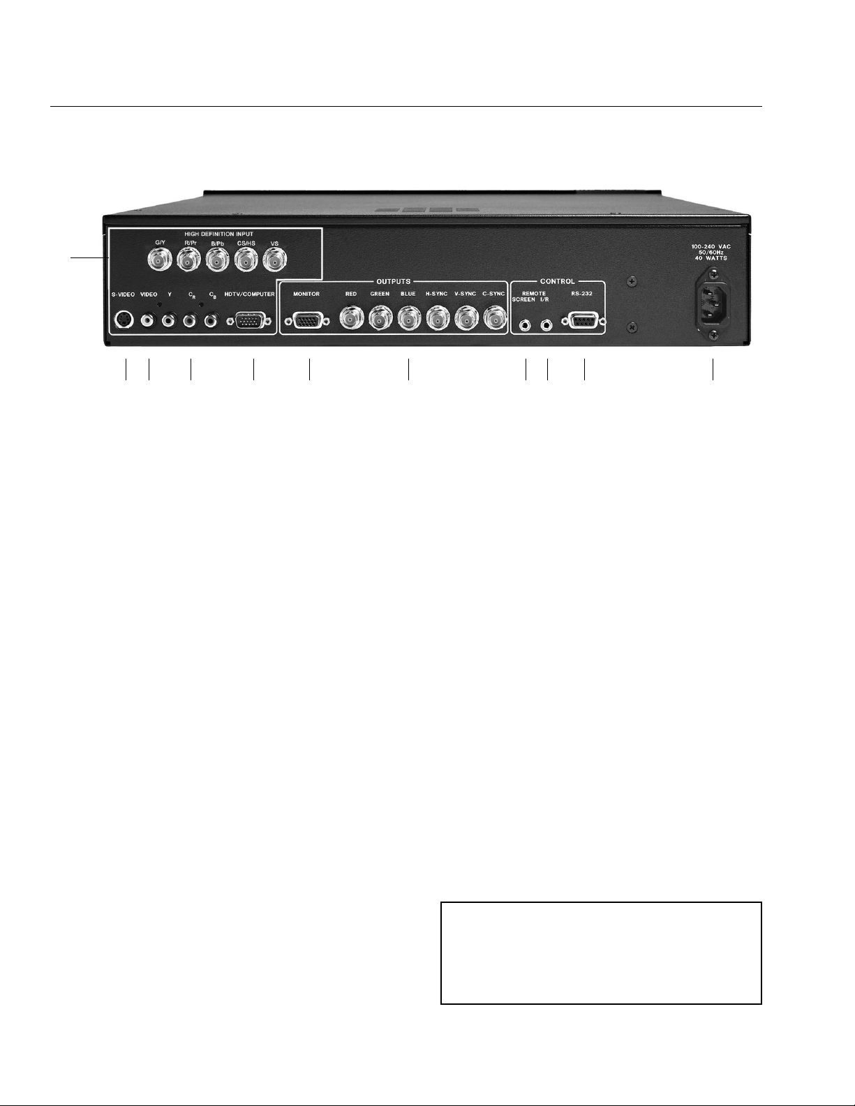
REAR PANEL I/O
Inputs
11. HDTV Input (BNC)
11. S-Video (4 Pin DIN)
12. Composite Video (RCA)
13. Component Video
Interlaced or Progressive(RCA)
14. HDTV/Computer (D15M)
10. AC Power
Outputs
15. RGBHVC, YUV or YPrPb (D15F)
16. RGBHVC, YUV or YPrPb(BNC)
Control
17. Screen Trigger (12V , 3.5mm , 2or 3pin)
18. Remote IR sensor (5V, 3.5mm, 3pin)
19. RS232 Port (D9F)
4
INSTALLATION
Inventory
1-DVP5000 1- Remote + Batteries
1-Owner’s Manual 2- Rack Mount Ears
1- Power Cord 1- Warranty Card
12 3 4 5 6 78 9 10
11

INSTALLATION
5
CONNECTIONS
Because of the high performance of the
DVP5000 it is very important to use the highest
quality cables possible, for both input and output signals.
Both the RGB BNC and the D15 Monitor output
connections are active at all times and can run
two displays simultaneously.
To avoid AC ground loop problems, the source
equipment, DVP5000 and projector should all
be running on the same AC power line (one
correctly rated for the power requirements).
SOURCE INPUTS
11. S-Video (Y/C) sources such as DVDs,
Satellite systems, S-VHS tape decks
(when using S-VHS tapes only), Hi-8 tape
decks.
12. Composite video sources such as
Laserdisc players, cable TV, VHS tape
decks, 8mm tape decks.
13. Interlaced Component video sources such
as DVDs and professional tape decks.
Progressive Component signals from
DVDs are also connected here.
14. High scan rate sources such as computers
as a pass-through to the projector.
Contrast can be adjusted for this input.
11. HDTV Input from HDTV tuner or tape deck.
OUTPUTS
15. D15F connector for use with computer
monitors or to a second display device.
16. BNC connectors for main output to display
devices. For YPrPb outputs use:
Red = Pr
Green = Y
Blue = Pb
Note: If HDTV or Computer signals are to be
used, the projector must have separate
H & V sync cables installed.
CONTROL
17. 12V trigger to activate automatic
screen relays.
18. IR receiver connection allows for use with
external IR receivers so unit can be
installed behind walls.
19. RS232 D9F connection for use with RS232
control systems
10. AC Power connection.
12 3 4 5 6 78 9 10
11
 Loading...