

Meridian Audio DVP-1510 Owners manual
DVP1510
Digital Video Processor
Installation and
Operations Manual
NTSC/PAL Model
™

QUICK START
INSTRUCTIONS
The DVP1510 requires only a few adjustments to
be set for proper operation. However, since the
processor must be integrated with a display device,
and the settings on one will affect the other, careful
attention must be made to the settings on both
products.
CONNECTIONS
Read the complete Owner’s Manual for the DVP1510
before installation.
Also review the owner’s manual of the display. Most
display devices require specific settings to properly
integrate with an external processor.
Be sure to connect all sources to the proper inputs of
the DVP1510.
Note on DVDs: For proper aspect ratio and to insure
the highest quality image from the DVD player, be
sure to set the DVD screen shape to 16:9 in the DVD
player's Setup menu. See the DVD player's owner's
manual for details
Connect the proper cables from the output of the
DVP1510 to the display device and audio processor.
Be sure the cables are not crossed.
DVP1510 SETUP
• Plug the processor into the wall power.
The unit will go through initialization identifying
the output resolution.
• Turn the unit on and press the Setup button
on the front panel to enter the Setup menu.
Press Return to return to the User Menu.
• Use the Function Up/Down buttons to select
different Functions, press the Left/ Right
buttons to change Values.
• Select Digital (DVI) or Analog (BNCs) output
• Select output type. When using the analog
output, RGBHV is recommended.
• Select the proper output scan rate.
• Composite Sync on H should be Off.
• Select the screen shape of your display.
DISPLAY POSITION AND
ALIGNMENT
The next step in the setup procedure is to align the
display device to the processor. Be sure to follow all
directions for setting up the display found in the
display’s manual. Using a test DVD with the Safe
Area test pattern, align the image size, position and
blanking first using the controls found in the display
device. Only use these controls in the DVP1510 if the
display device does not offer these controls or if there
is not enough range.
Note: Some displays do not respond to the H & V
position controls when using DVI.
SETTING DISPLAY PROFILES
The DVP1510 stores up to eight profiles for NTSC
and eight profiles for PAL. Each profile stored
contains all the settings for the unit at the time the
information was stored. This allows the installer to
store scan rates, screen shapes, etc. for multiple
displays that may be using in the theater. Store the
current settings by selecting the profile number (1-8)
in the OSD and then hit Store on the remote. Profiles
can also be stored in the Setup menu. See the
manual for more details.
IMAGE ALIGNMENT
The final step is optimizing the image. Use a test
pattern DVD to optimize the display and processor.
Set the brightness and contrast using the controls in
the display.
Adjust the gray scale of the display using the color
temperature controls in the display.
Reduce the detail or sharpness control in the display
to 0 or 1 (if available).
Using video material, adjust the Detail on the
DVP1510. Use of the Detail circuit is affected by the
quality of the material being viewed. High quality
sources need a lower Detail setting. DVDs or satellite
sources that are poor quality (compression artifacts)
can be cleaned up by reducing the detail level. Low
bandwidth sources such as VHS can be improved by
increasing the detail. Customized settings can be
stored as Profiles.
a
QUICK START OPERATION MENU

image could be burned in to the display device. Use
special care when projecting video games or
computer program images.
About the installation place
Do not install the processor in a place that cannot
support its weight securely, or that does not allow
for proper heat ventilation.
IMPORTANT SAFEGUARDS
IMPROPER USE OF THIS EQUIPMENT CAN
RESULT IN POTENTIAL ELECTRICAL SHOCK
OR FIRE HAZARD.
In order not to defeat the safeguards incorporated
into this product, observe the following basic rules for
its installation, use and service.
– All the safety and operating instructions should be
read before the product is operated.
– The safety and operating instructions should be
followed and retained for future reference.
– All warnings on the product and in the operating
instructions should be adhered to.
– Unplug this product from the wall outlet before
cleaning. Do not use liquid cleaners or aerosol
cleaners. Use a damp cloth for cleaning.
– Do not use attachments not recommended by the
product manufacturer as they may be hazardous.
– Do not use this product near water. Do not use
immediately after moving from a low temperature to
high temperature, as this causes condensation,
which may result in fire, electric shock, or other
hazards.
– Do not place this product on an unstable cart,
stand, or table. The product may fall, causing serious
injury to a child or adult, and serious damage to the
product. The product should be mounted according
to the manufacturer’s instructions, and should use a
mount recommended by the manufacturer.
– When the product is used on a cart, care should be
taken to avoid quick stops, excessive force, and
uneven surfaces which may cause the product and
cart to overturn, damaging equipment or causing
possible injury to the operator.
– Slots and openings in the cabinet are provided for
ventilation. These ensure reliable operation of the
product and protect it from overheating. These
openings must not be blocked or covered. (The
openings should never be blocked by placing the
product on bed, sofa, rug, or similar surface. It should
not be placed in a built-in installation such as a
bookcase or rack unless proper ventilation is
provided and the manufacturer’s instructions have
been adhered to.)
iii
SAFETY PRECAUTIONS
SAFETY
PRECAUTIONS
IMPORTANT INFORMATION
WARNING : TO PREVENT FIRE OR SHOCK
HAZARDS, DO NOT EXPOSE THIS APPLIANCE
TO RAIN OR MOISTURE.
CAUTION :
To reduce the risk of electric shock, do not remove
cover. Refer servicing to qualified service personnel.
This product is equipped with a 3-blade groundingtype plug to satisfy UL, CUL, TUV, FCC rules.
If you are unable to insert the plug into the outlet,
contact your electrician.
FCC INFORMATION (U.S.A. ONLY)
CAUTION :
Changes or modifications not approved by Faroudja
could void the user’s authority to operate the
equipment.
Note: This equipment has been tested and found to
comply with the limits for a Class B digital devices,
pursuant to Part 15 of the FCC Rules. These limits
are designed to provide reasonable protection
against harmful interference in a residential
installation. This equipment generates, uses, and can
radiate radio frequency energy and, if not installed
and used in accordance with the instructions, may
cause harmful interference to radio communications.
However, there is no guarantee that interference will
not occur in a particular installation. If this equipment
does cause harmful interference to radio or television
reception, which can be determined by turning the
equipment off and on, the user is encourage to try to
correct the interference by one or more of the
following measures:
– Reorient or relocate the receiving antenna.
– Increase the separation between the equipment.
– Connect the equipment into an outlet on a circuit
different from that to which the receiver is connected.
– Consult the dealer or an experienced radio/TV
technician for help.
About burning-in of the display device
Do not allow the same still picture to be projected for
a long time or an abnormally bright video picture to
be projected. Do not project video images with highintensity or high contrast on a screen. The video

– This product should be operated only with the type
of power source indicated on the label. If you are not
sure of the type of power supply to your home,
consult your product dealer or local power company.
– This product is equipped with a three-wire plug.
This plug will fit only into a grounded power outlet. If
you are unable to insert the plug into the outlet,
contact your electrician to install the proper outlet. Do
not defeat the safety purpose of the grounded plug.
– Power-supply cords should be routed so that they
are not likely to be walked on or pinched by items
placed upon or against them. Pay particular attention
to cords at doors, plugs, receptacles, and the point
where they exit from the product.
– For added protection of this product during a
lightning storm, or when it is left unattended and
unused for long periods of time, unplug it from the
wall outlet and disconnect the cable system. This will
prevent damage to the product due to lightning and
power line surges.
– Do not overload wall outlets, extension cords, or
convenience receptacles on other equipment as this
can result in a risk of fire or electric shock.
– Never push objects of any kind into this product
through openings as they may touch dangerous
voltage points or short out parts that could result in a
fire or electric shock. Never spill liquid of any kind on
the product.
– Do not attempt to service this product yourself as
opening or removing covers may expose you to
dangerous voltages and other hazards. Refer all
service to qualified service personnel.
– Unplug this product from the wall outlet and refer
service to qualified service personnel under the
following conditions:
a) When the power supply cord or plug is damaged.
b) If liquid has been spilled, or objects have fallen on
the product.
c) If the product has been exposed to rain or water.
d) If the product does not operate normally by
following the operating instructions. Adjust only those
controls that are covered by the Operation Manual,
as an improper adjustment of controls may result in
damage and will often require extensive work by a
qualified technician to restore the product to normal
operation.
e) If the product has been dropped or damaged in
any way.
f ) When the product exhibits a distinct change in
performance – this indicates a need for service.
– When replacement parts are required, be sure the
service technician has used replacement parts
specified by the manufacturer or with same
characteristics as the original part. Unauthorized
substitutions may result in fire, electric shock, or
other hazards.
– Upon completion of any service or repairs to this
product, ask the service technician to perform safety
checks to determine that the product is in proper
operating condition.
– The product should be placed more than one foot
away from heat sources such as radiators, heat
registers, stoves, and other products (including
amplifiers) that produce heat.
– When connecting other products such as VCR’s,
and personal computers, you should turn off the
power of this product for protection against electric
shock.
– Use only the accessory cord designed for this
product to prevent shock.
The power supply voltage rating of this product is AC
120 V, the power cord attached conforms to the
following power supply voltage. Use only the power
cord designated by our dealer to ensure Safety and
EMC. When it is used by other power supply voltage,
power cable must be changed.
Ensure that the power cable used for the projector is
the correct type for the AC outlet in your country.
Consult your product dealer.
*DO NOT allow any unqualified person
to install the unit.
Be sure to ask your dealer to install the unit since
special technical knowledge and skills are required
for installation and connection to multiple devices.
If installation is performed by an unqualified person,
it may cause personal injury or electrical shock.
iv
SAFETY PRECAUTIONS

Processor
Quick Start ................................................................a
Installation ................................................................2
Connections .............................................................2
Connecting HDTV Satellite Receivers .......................3
Front Panel Control ..................................................4
System Firmware Setup ...........................................4
Processor IR Remote and
On-Screen-Display Operation ..................................6
Operating the Processor ..........................................6
Test Pattern List ........................................................9
RS232 Programming Instructions
and Commands ........................................................9
Help Menus ............................................................12
Specifications .........................................................14
Warranty .................................................................65
DVD Operation
01 Before You Start
Disc / Content Format Playback Compatibility .......15
Using the remote control.........................................17
02 Getting Started
Using the on-screen displays..................................18
Setting up with the Setup Navigator .......................18
03 Playing Discs
Introduction .............................................................21
Using the Disc Navigator to browse
the contents of a disc..............................................25
Copyright ©2004 by Faroudja
®
No part of this document may be copied, photocopied, translated, or reproduced to any electronic medium or
machine readable form without prior consent, in writing, from Faroudja.
The Faroudja name, logo and Picture Plus are registered trademarks of Faroudja.
Specifications subject to change without notice. All Rights Reserved.
The Faroudja DVP1510 is covered by the following United States patents:
4,030,121, 4,179,705, 4,240,105, 4,262,304, 4,847, 681, 4,864,389, 4,876,596, 4,893,176, 4,916,526,
4,967,271, 4,982,280, 4,989,090, 5,014,119, 5,025,312, 5,159,451, 5,237,414.
A Division of Genesis Microchip Corp.
Made in USA
TABLE OF CONTENTS
1
Rev. 9/04
Scanning discs ........................................................27
Playing in slow motion.............................................28
Looping a section of a disc .....................................29
Using repeat play.....................................................30
Using random play ..................................................31
Creating a program list............................................32
Other functions available from
the program menu...................................................34
Searching a disc......................................................35
04 The Audio Settings Menu
Audio DRC...............................................................39
Virtual Surround.......................................................40
Channel Level..........................................................41
05 The Video Settings Menu
Video Adjust ............................................................43
Creating your own output presets...........................43
06 The Initial Settings Menu
Using the Initial Settings menu................................44
Digital Audio Out settings........................................44
Video Output settings..............................................46
Language settings ...................................................47
Display settings .......................................................49
Options....................................................................50
Speakers..................................................................54
07 Additional Information
Language code list ..................................................58
Country code list .....................................................58
INSTALLATION
Unpacking
Remove the DVP1510 unit from the shipping
container and examine it for any signs of shipping
damage or missing items (check inventory list below).
All shipping materials should be saved if the unit is to
be moved or returned for service. Shipping unit back
to Faroudja for service not in the original box may
result in voiding warranty or additional cost.
Placement
The processor can be either placed on a table or rack
mounted. A rack mounting installation kit is included.
Securely mount the side rack brackets with the
screws that are provided with the kit.
Ventilation
The unit uses convection to cool. A fan is not
needed. As hot air raises out of the top vent, cool air
is drawn in from the bottom and side. These vents
must not be blocked. When rack mounted, a
minimum of 1.75” (1 rack unit height) of free space is
required above and below the unit to allow for proper
cooling. A forced air fan should be added to the rack
installation if power amps are located in the same air
space. Do not install unit above power amps.
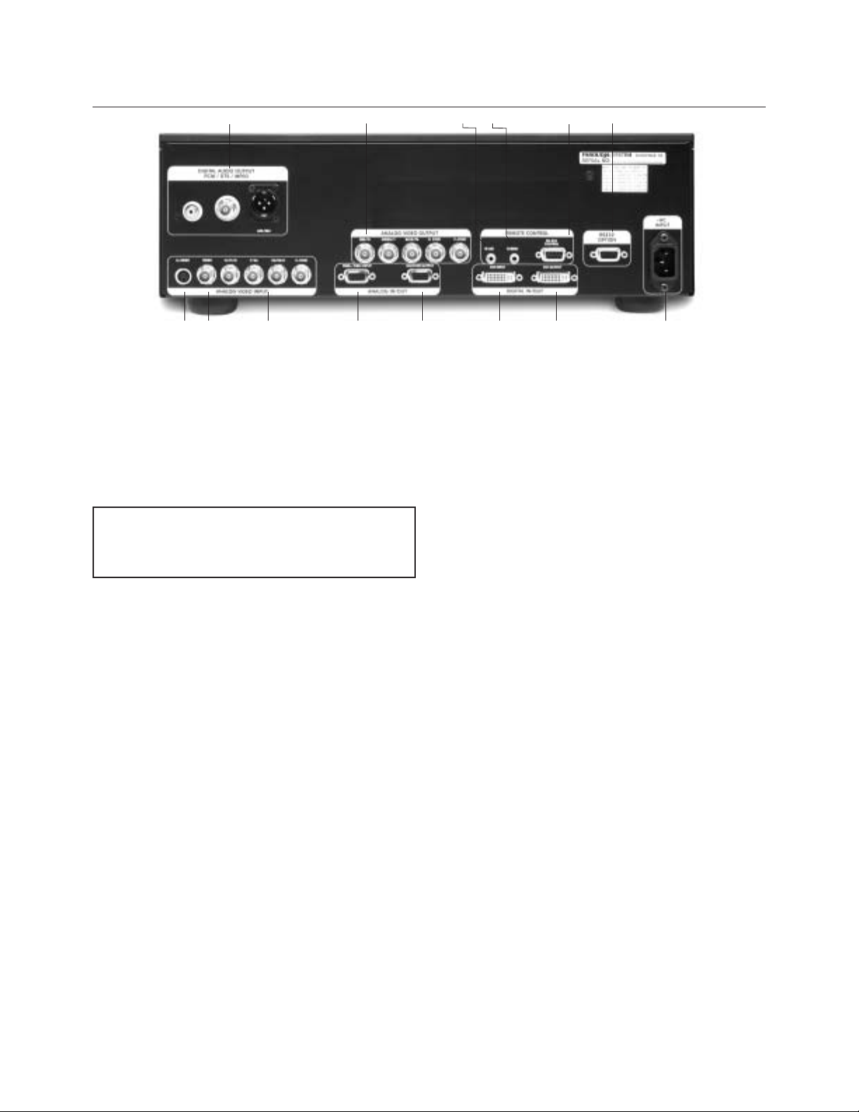
Connections
Because of the high performance of the DVP1510
unit it is very important to use the highest quality
cables possible, for both input and output signals.
To avoid AC ground loop problems, the source
equipment, DVP1510 unit and projector should all be
running on the same grounded AC power line (one
rated for the power requirements).
1. S-Video input (4-pin DIN) for sources such as
DVDs, Satellite systems, S-VHS tape decks
(when using S-VHS tapes only),
Hi-8 tape decks.
2. Composite video input (BNC) for sources such
as Laserdisc players, cable TV, VHS tape
decks, 8mm tape decks.
3. YPrPb/RGBs Input (BNC): 480i and HDTV
scan rates are sent to the internal processor
and then output at the selected scan rate. If
the output is set to analog RGBHV or digital
DVI, the unit will automatically transcode the
YPrPb HDTV to RGBHV.
Note on DVDs: For proper aspect ratio and to
insure the highest quality image from the DVD
player, be sure to set the DVD screen shape
to 16:9 in the DVD player's Setup menu. See
the DVD player's owner's manual for details.
4. High scan rate input (D15F) for sources such
as HDTV signals or computers are passed
through to the projector. The signal is sent to
the outputs in the same format as the input
unless Transcoding is selected. YPrPb from
HDTV sources can be transcoded to RGBHV,
as well. Use a BNC to D15 breakout cable if
necessary. The Green, Red, Blue BNCs are
used for YPrPb.
5. D15F connector output for use with computer
monitors or to a second display device. Use
only short cable runs. This output can be used
at the same time as the BNC outputs.
6. DVI Input. The DVI Input will automatically
process 480P,720P and 1080i signals.
Computer rates are passed through to the DVI
output if any of the pass-through inputs are
selected. The DVP1510 will not convert a
computer DVI output to the analog output.
7. DVI Output: Digital output interface for
compatible displays. All processed analog
and digital inputs are output to this connector
as well as computer scan rates when the
pass-through input is selected. Maximum
cable length is 30ft with a high quality DVI
cable. For longer lengths a distribution system
or fiber optic system must be used.
8. BNC connectors for main output with RGBHV
or YPrPb signals to display devices. Cable
runs up to 100ft are okay if good quality cables
are used. For YPrPb outputs use:
Red = Pr
Green = Y
Blue = Pb
RGBHV is recommended.
2
INSTALLATION
Inventory
1-DVP1510 Unit 1- Remote + Batteries
1-Owner’s Manual 1- Warranty Card
1- Power Cord
12 34567
8
910
12
11
13
14
INSTALLATION
Note: YPrPb output can only be used with the
720p and 540p output rates.
9. IR receiver connection allows for use with
external IR receivers so unit can be installed
behind walls. (3.5mm, 3 pin, Tip = +5 - +12V
Pulse, Sleave = Gnd)
10.12V trigger to activate automatic screen
relays. Voltage is constant when unit power is
on. (12V @ 100mA Max. 3.5mm 2 pin
connector, Tip = +12V, Sleave = Gnd)
11. RS232 D9F connection for use with RS232
control systems. This connection also allows
for firmware upgrades.
12. AC Power connection.
13. RS232 Output - Not Active - for future upgrades
14. Digital Audio Outputs (RCA, Coaxial,
AES/EBU). Be sure the audio processor is
compatible with the audio formats used.
These outputs are always active.
Note: The DVI or analog RGBHV outputs cannot be
active at the same time. Select the output type in the
Setup menu prior to use of the processor.
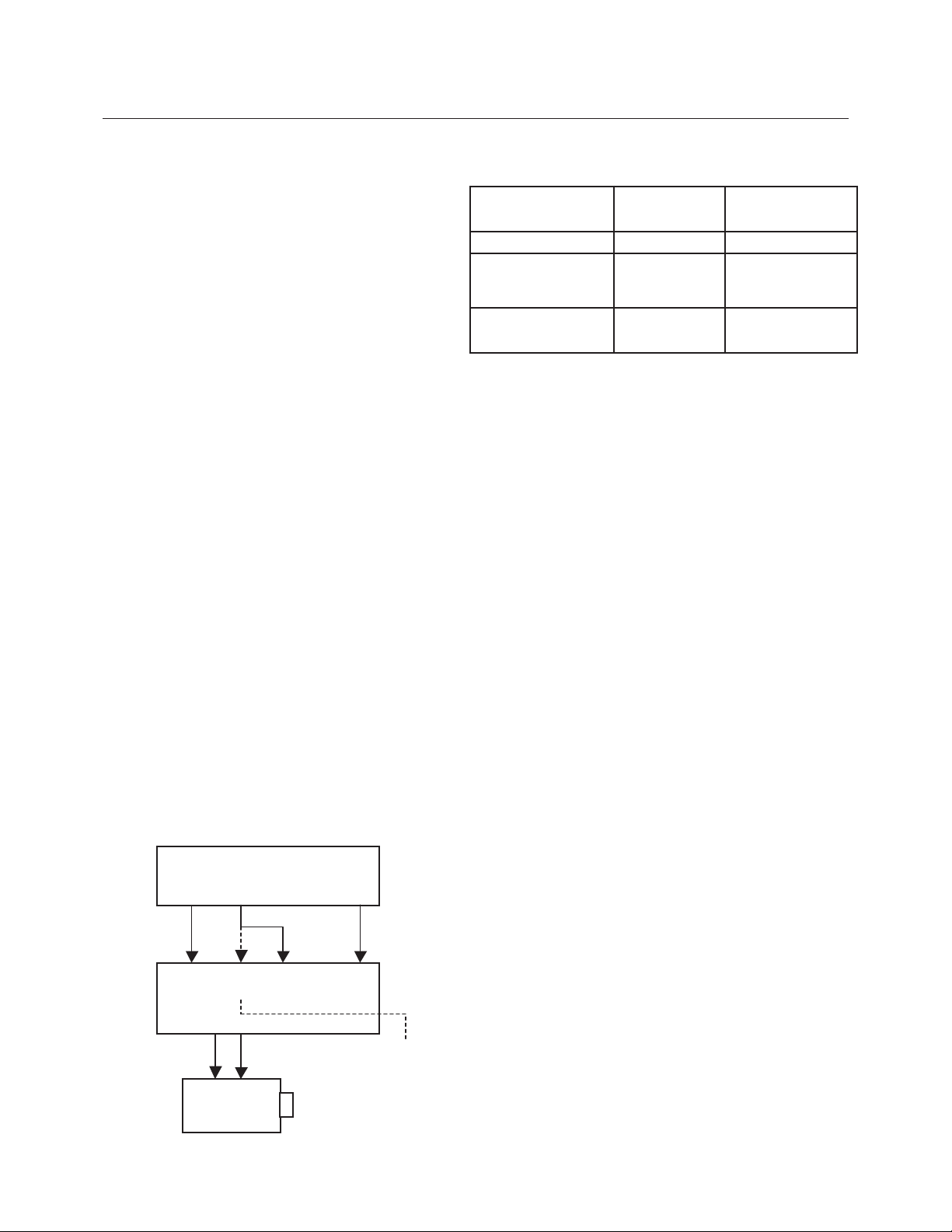
Connecting HDTV Satellite Receivers
Since HDTV ready satellite receivers offer different
signal types, they require special attention for
connection to the processor. Every receiver is
different so be sure to consult the receivers manual
for details. For this manual, we will assume the
receiver being used operates as follows:
1. Non HDTV material is output from the receiver
via an S-video connection
2. HDTV material is output via YPrPb outputs
3. If available, HDTV material is also output via a
DVI connector.
The following diagram offers one way to connect the system.
Note: The pass-through input will “pass ” the input
signal to the output stage in the same format as the
input signal, i.e. analog HDTV in – analog HDTV out,
DVI HDTV in – DVI HDTV out.
HDTV Cross-Conversion
The DVP1510 can cross-convert 480p, 720p and
1080i HDTV signals to the selected output of the
processor. Any HDTV signal connected to the YPrPb
BNC or DVI inputs will be cross-converted. Any
HDTV or PC signal connected to the D15 input will be
passed-through without processing. PC signals via
the DVI input will be sent to the pass-through.
To pass-through HDTV signals to avoid processing,
select the passthrough input. The DVI input is
passed through to the DVI output. The analog YPrPb
input is passed through as analog RGB (when
transcode is selected).
HDCP Compatibility
The DVP1510 is a HDCP (High Definition Content
Protection) compatible processor. This means that
when used with a HDCP encrypted source (satellite
and DVD via DVI) and a HDCP compatible display
device, the digital signal can be processed and
viewed on the display device. If a non-HDCP source
is used, the image can also be viewed (Note: check
the display device manual to be sure this is possible
when using the DVI input). If a non-HDCP compatible
display is used, HDCP encrypted sources cannot be
viewed.
Note: When first selecting a HDTV source with
HDCP there can be an interruption of the video
image for up to 20 seconds while the HDTV source
unit communicates with the display device to verify
compatibility.
HDMI Connectors
To use sources or displays that use the HDMI
connector, simply use a HDMI to DVI converter cable
(Not supplied. See www.pacificable.com).
With this hookup viewing the different sources is as follows:
SOURCE USE THIS USE THIS
INPUT OUTPUT
Non-HDTV YPrPb or S-Video DVI or RGBHV
HDTV Rates (480p,
720p,1080i) with YPrPb or DVI DVI or RGBHV
and without HDCP
Computer VESA RGB RGBHV or DVI
1024x768 (D15) or (DVI) Pass-Through
S-Video
YPrPb
RGBHV
DVI S-Video
DVI
YPrPb
HD/PC
DVI
3
Satellite Receiver
Input
Input
Conn.
Input
DVP1510
HDTV
Alt.
Input
Display
Set Pass-Through
input to Transcode
4
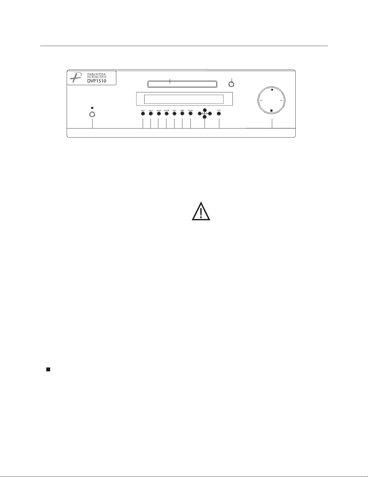
FRONT PANEL CONTROL
1. Power/ Standby: Press to turn on (Green LED) or
for Standby (Red).
The following list of buttons are used in case the remote
control is not available. In some cases, the selection can
be made by either repeatedly pressing the button to
cycle through the available functions or by pressing the
button and then using the left/right directional buttons.
2. Input: Push to cycle through available inputs. DVD Video - S-Video - RGB - YCrCb - DVI - Pass Through - Pass-Through transcode
3. Aspect Ratio: Press to cycle through options.4:3 Letterbox - Anamorphic
4. Profile: Store up to eight image profiles for NTSC
and eight for PAL. All image parameters are stored
including output scan rate.
5. Factory: Press to recall Factory preset levels for
Brightness, Contrast, Color, Tint and Detail
6. Setup: Press to enter the processor setup menu.
Use the Up/Down buttons to cycle through the
available functions. Press the Left/Right buttons to
make changes to the selected function.
7. Menu: Press to access the DVD disc menu.
8. Return: Press to return the front panel control to the
main picture settings menu.
9. Directional Buttons: Press to make changes to the
processor settings. When in the DVD menu, press
to navigate the DVD menu.
10.Enter: Press to enter selections when prompted by
a menu item either with the processor setup
functions or when in the DVD menu.
11. DVD transport controls.
. Press to stop
II>. Press to toggle between Play and Pause
>>. Press to skip forward. Hold to Fastforward.
<<. Press to skip backwards. Hold to Rewind.
SYSTEM FIRMWARE SETUP
Now that all the sources and cables are connected,
the processor’s firmware needs to be setup for the
installation. Be sure to go through the Setup menu
before doing the final setup of the display.
When the unit is first plugged in it will go through an
initializing procedure and display the output resolution.
Do not send any commands to the unit during this
initialization period. Once this initialization is
completed the unit is instant-on.
Note: All display devices have specific setup
steps that must be completed to insure
proper operation with the DVP1510 and
other sources. Be sure to carefully
follow those instructions as well as
the instructions for this processor.
To enter the Setup menu, press the Setup button on
the front panel. Setup Functions can only be viewed
on the front panel LCD, not from the OSD.
Press the Function Up or Down to select the available
Functions. Press the Value Up or Down keys to
change values or to select options.
SETUP MENU FUNCTIONS
Set: NTSC SCAN RATE
Select the required scanrate by using the right and
left arrows. When the desired rate is displayed on the
LCD display, press the Enter key. The scanrate is
now selected.
Set: PAL SCAN RATE
(This new command is in addition to the NTSC scan
rate selection. When the processor detects a PAL
signal, the output rate will switch to the rate
selected here.)
Set: Active Output
Analog/Digital (Default)
This must be selected to determine if the Analog
(BNC) or Digital (DVI) output is used. Both outputs
cannot be used at the same time.
Set: Screen Shape
Wide Screen / 4:3 / Wide 4:3
Note: This sets the processor for the screen shape of
the display to be used. If this is not set properly, the
aspect ratio selection for the different sources
located in the user menu will be incorrect.
• Wide Screen-Choose this when the screen is
Widescreen and the projector will provide the
anamorphic vertical squeeze.
SETUP
12345678 9 10
DVD Tray
Open/Close
11

SETUP
Example: A 16:9 plasma, a digital or CRT projector
set to Anamorphic using a wide angle screen or when
using a Panamorph lens, or a 1280x720 digital
projector.
• 4:3 – Choose this when the projector is 4:3
and the screen is 4:3
Example: using a 1024x768 digital projector on a 4:3
screen.
• Wide 4:3-Choose this when the digital
projector operates as 4:3 and the screen is
Widescreen. (Not available on units scanning
at rates below 720p)
Example: A digital projector that has a 4:3 display
chip that locks the aspect ratio when sent the native
resolution and then displayed on a wide angle screen.
Set: Black Level
0 (Default)-7.5
Note: This sets the correct setup level for the
component input only. It can be used to get correct
black levels for certain displays. In most cases it
should be left at 0.
Set: DVI Input Level
0-255 (Default) / 16-235
Note: This sets the correct level range for the DVI
input. 0-255 is correct for video sources, 16-235 is a
range sometimes used by computer video cards.
Output Format (Analog)
RGB (Default) /YPrPb
Note: Selecting RGB means connecting the
processor to the display via five wire analog RGBHV.
This function is not active when DVI output is
selected. DVI is always RGBHV.
Composite Sync on H
On/Off (Default)
Note: this function is not active when YPrPb output
is selected
Note: Each input on the DVP1510 can be activated
or deactivated to simplify operation so unused inputs
are not accessed when cycling through the inputs
with the remote control.
Set: Video Input
Enabled (Default) /Disabled
Note: Disabling this unused input will remove it from
the input menu list.
Set: S-Video Input
Enabled (Default) /Disabled
Note: Disabling this unused input will remove it from
the input menu list.
Set: RGB Input
Enabled (Default) /Disabled
Note: Disabling this unused input will remove it from
the input menu list.
Set: YCrCb Input
Enabled (Default) /Disabled
Note: Disabling this unused input will remove it from
the input menu list.
Set: DVI Input
Enable / Disable
Note: Disabling this unused input will remove it from
the input menu list.
Set: Passthru Input
Enabled (Default) /Disabled
Note: Disabling this unused input will remove it from
the input menu list.
Set: Passthru Transcode
Disable (Default) /Enable
Note: YPrPb HDTV signals via the D15 input or the
YPrPb (BNC) inputs can be transcoded to RGB
when this feature is enabled.
Set: Component Input Standard
DVD (Default) /Professional (Betacam)
Note: Only use professional setting when using
a device that conforms to SMTPE Betacam levels
Set: RGB Input Sync
Sync-on-Green (Default) /TTL/Video
Set: DVI Input H-Sync
Normal / Wide
Note: If the input from a DVI source is unstable,
try this adjustment.
OSD (On Screen Display)
On (Default) /Off
OSD Timer
0-255 (30 default)
LCD Timer
6-255 (40 Default)
Note: setting the timer to 5 or lower sets the LCD
backlight to Always On.
Set: RS232 Echo
On (Default) /Off
Note: Allows RSR232 characters to be sent back to
the controller.
Set: Baud Rate
19200 (Default) / 57600 / 9600
Set to match control system
Set: Store NTSC profiles 1-8
Set: Store PAL profiles 1-8
Set: Restore Factory
Are You Sure? - Press Enter Key
Use this Function only in the event that
the processor no longer functions properly and
all other system checks have been performed. This
command will erase all custom settings and restore
the original firmware configuration. Be sure to go
back through the Setup procedure for proper
operation.
The next step in the setup procedure is to
align the display device. Be sure to follow
all directions for setting up the display
found in the display’s manual. Using a test DVD with
the Safe Area test pattern, align the image size,
position and blanking first using the controls found in
the display device. Only use these controls in the
DVP1510 if the display device does not offer these
controls or if there is not enough range.
5

IR LEARNING REMOTE
The DVP1510 ships with a learning remote control
that contains the codes for the video processing
stage and the DVD drive. Control codes for
Faroudja’s other display products are also stored.
See the separate manual on the remote control for
programming instructions.
To recall a Profile, press (PROFL)
+ (#) enter a number 1-8.
Press the DVD DRIVE
button to access the
DVD drive commands
Press the buttons for direct access.
Change levels by either using the
value keys or entering a 3 digit
number. Some buttons are toggles
between selections. See chart for
creating direct access marcos.
Press VIDEO PROCESSOR to
access the controls for the video
processing stage. Press DVD
DRIVE to access the DVD
transport controls.
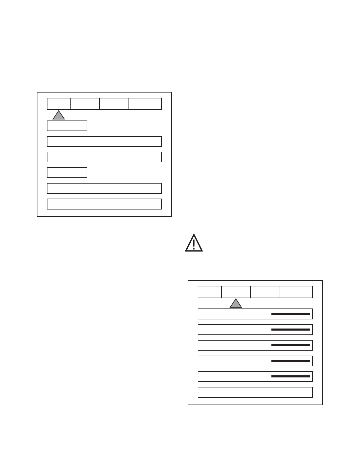
ON SCREEN DISPLAY (OSD)
Accessing the OSD
• Press Menu button to bring up main Index.
• Use Function Up/Down Keys until the triangle
at the top of the OSD turns yellow.
• Use the Left/Right keys to move to the next
menu page. A list of available Functions
will appear.
• Press Function Up/Down keys to select
an adjustment.
• Use Value Left/Right keys to adjust.
The main menu drops away and a single
line menu appears.
• Use the Function keys to return to the drop
down menu.
• Press Menu at any time to cancel OSD
Note: Unused inputs can be deactivated for simpler
operation of the processor. See the Setup
instructions for details.
6
IR REMOTE
INPUT PICTURE DISPLAY PATTERNS
FORMATS
INPUTS DVD
ASPECT ANAMORPHIC
PROFILE
RECALL F 1 2 3 4
STORE 1 2 3 4
Press the Function UP/Down
keys until the triangle turns
Yellow. Press the Value Left/Right
keys to cycle to the Menu tabs.
Use the Value left/Right
keys to change selection
or values.
Touch Panel
Cycle to next
touch panel
Directional
Controls
Press Menu to
recall main
remote menu
FUNCTION MACRO COMMANDS
Pass-Through (Pass-T) + (0)
Pass-Through (Pass-T) + (1)
Transcode
DVI (DVI) + (0)
RGB (DVI) + (1)
Page 1
DVD Video
S-Video YCrCb
DVI PasT
RGB PastX
Menu Menu
on Off
Page 1
Video Processor
DVD Drive
Plasma
DILA
Page 1
Page 2
CLR TNT DTL
Contrast Bright
Profile Store
4:3 Let ANA
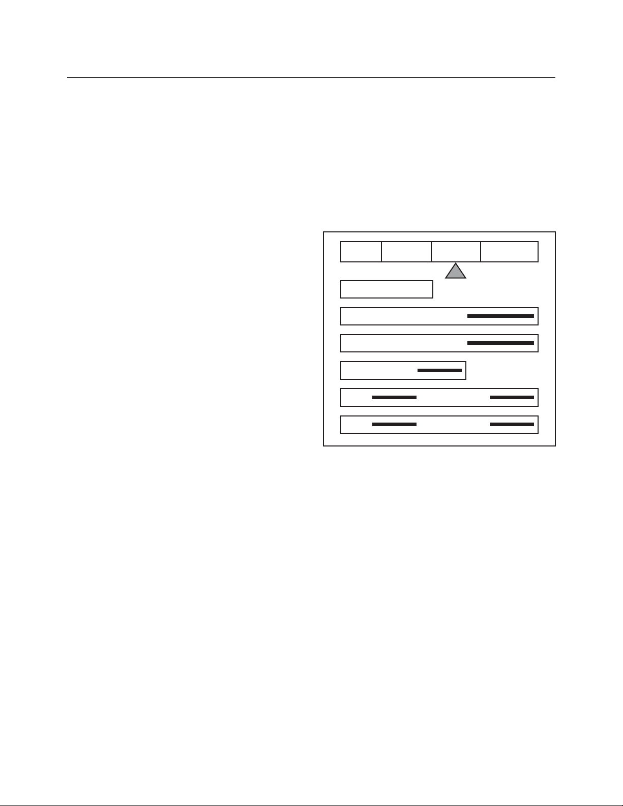
The OSD consists of four menu tabs:
Input – Picture – Display – Patterns
Input Menu
Formats
Input Select: OSD
Video-S-Video- RGB-YCrCb-DVI
Note: Note: The Pass-Thru input cannot be selected
from the OSD since an OSD is not available on that
input. Use the Input button on the remote to select it.
The DVI Input will not display an OSD unless there is
a source connected to it.
Aspect Ratio
4:3-Letterbox-Anamorphic
Note: This selection should match the aspect ratio of
the source, not the display. The aspect ratio of the
display should be selected in the Setup menu.
Profiles-
Profile: Factory-1-2-3-4-5-6-7-8
Store: 1-2-3-4-5-6-7-8
To store a Profile (in the Input Menu):
• Press Menu button on the remote
• Make all required adjustments.
• Use the Function Up/down keys
to select Profile
• Use the Value Left/Right keys to select Profile
• Press Store
To recall a Profile (in the Input menu):
• Press Menu button on the remote
• Use the Function Up/Down keys to
select Recall
• Use the Value Left/Right keys to
select profile 1-8
• Press Store
• There are separate banks of eight Profiles
for NTSC and PAL
Note: When using a 4:3 source on a Wide Angle
screen there are black bars on the left and right of the
image. The sidebars can be changed to gray using
the Blanking Level control located in the Display
menu. If filling the entire screen is desired, select
Letterbox. The image will fill the screen but the top
and bottom 1/3 of the image will be cut off
(overscanned).
When watching 2:35 aspect ratio movies on a 16:9
(1:77) screen, it is normal to see black bars at the top
and bottom of the image.
Note: The screen shape used in the installation
must be set in the Setup Menu during installation for
proper Aspect Ratio mapping. Anamorphic Aspect
Ratio with 4:3 screens and the Wide-4:3 settings are
not available on units with scan rates, 540p, 600p
and Frame Doubling. See Setup section for details.
Note: Do not leave the 4:3 image with a Wide Angle
screen on for long periods of time on a CRT
projector or plasma display. This can cause
permanent image burn-in. Image burn-in is
not covered by Faroudja’s warranty
Picture Menu
Use these commands to fine-tune the image.
Brightness
Factory 50
7
OSD / OPERATING INSTRUCTIONS
INPUT PICTURE DISPLAY PATTERNS
FORMATS
INPUTS DVD
ASPECT ANAMORPHIC
PROFILE
RECALL F 1 2 3 4
STORE 1 2 3 4
INPUT PICTURE DISPLAY PATTERNS
BRIGHTNESS 50
CONTRAST 50
COLOR 50
TINT 50
DETAIL 4
ADVANCED COLOR SYS NORMAL
Contrast
Factory 50
Note: It is best to set Brightness and Contrast levels
using the controls of the display with the proper test
pattern and with the DVP1510 in the Factory default
setting for the initial setup. This means with day-to-day
use, when the Factory preset button is pressed, the
system is back to the original optimum settings, while
changes made for specific sources can be saved in the
custom Profiles.
Color
Factory 50
This adjusts the amount of color. The Faroudja
processor is calibrated to meet broadcast (SMPTE) color
specifications so only minor color adjustments should be
needed. Using DVI may require a lower chroma level.
Tint
Factory 50
Tint is not available with YPrPb or PAL sources
Detail
Factory 4
Note: The Detail circuit is a powerful tool for image
quality. The settings have been optimized for the output
scan rate and resolution. However, the viewer’s tastes
plus the types of software and display require making
adjustments of this setting to fine-tune the image. This
control is very effective to increase detail in poor quality
video material. It is recommended that adjustments be
made in small increments until the desired results are
achieved and then store these custom settings in the
Profiles. It is important to not use too much Detail
since the image will start to look artificial.
Typically, digital displays will need less detail than analog
displays. High quality software will need less detail than
poor quality ones. Reducing the Detail level can help to
reduce the visibility of MPEG artifacts on some DVDs
and satellite systems and noise with VHS tapes. The
best results are achieved by adjusting the levels to the
software being viewed instead of just using test patterns.
Advanced Color System
Normal (default) /Bypass
For some DVDs with computer animation or with very
high levels of color, the Faroudja patented chroma edge
processing circuits may not be needed and can be
turned off (Bypass). For most sources, the Normal
setting should be selected. These settings can be
stored as a Profile.
Note: Any changes to the picture level adjustments are
automatically stored after one minute has passed
without making any changes. This information is stored
separately for each input. As each input is selected the
last used settings will automatically be recalled. If picture
levels are adjusted but then the input is changed before
one minute has passed, the changes for that input will
not be stored and the previous settings will be recalled
the next time that input is used.
Display Menu
Use these commands to adjust the image position and
edge blanking. It is recommended to adjust sizing,
position and blanking in the display device first with the
DVP1510 in the Factory preset setting. Then use the
DVP1510 controls only if the display runs out of range or
does not offer these controls. This should be done by a
qualified technician.
Horizontal Position
(See chart on page 13 for default settings)
Moves image left or right of center.
Vertical Position
(See chart on page 13 for default settings)
Moves image up or down from center.
Note: Moving the image too far to the left or right can
cause the display to stop working. Move image to center
to correct. Use the positioning controls in the display
first– if available. Also, many display devices require a
specific setting when using high scan rate sources such
as the DVP1510 or HDTV. Be sure to completely read
the installation manual for the display device before
making adjustments.
Note: some displays do not respond to H & V
commands with DVI
8
OSD / OPERATING INSTRUCTIONS
INPUT PICTURE DISPLAY PATTERNS
POSITION
HORIZONTAL 25
VERTICAL 25
BLANKING LEVEL
LEFT RIGHT
TOP BOTTOM

OPERATING INSTRUCTIONS / RS232
9
Bottom Blanking
This adjusts the bottom edge blanking
Right Blanking
Adjusts the right edge blanking
Left Blanking
Adjusts the left edge blanking
Top Blanking
Adjusts the top edge blanking
Blanking Level
This adjusts the blanking from black to white.
This can be used to create a gray side bar for use
with 4:3 aspect ratio sources on wideangle screens
to help reduce the chance of image burn-in. Image
burn in is not covered by Faroudja’s warrantee.
Note: The DVP1510 will store unique blanking and
H&V position settings for each aspect ratio which are
automatically stored and recalled when the different
aspect ratios are selected
Patterns Menu
The best approach to system setup is to use a DVD
that offers the proper test patterns. This way, the
system is aligned for the entire signal path. If a test
DVD is not available, then use the internal test
patterns provided in the DVP1510.
Note: The test pattern generator in the DVP1510 is
set to SMPTE standards. To insure proper output
levels for display setup, the picture controls in the
DVP1510 cannot be accessed when the test
patterns are being used. Adjust levels, if needed,
in the display device.
INPUT PICTURE DISPLAY PATTERNS
TEST PATTERNS ON
SELECT CONVERGENCE
AVAILABLE PATTERNS:
10-step Gray Scale: Check gray scale
Cb Ramp: Check linearity of Cb channel
Cr Ramp: Check linearity of Cr channel
Black: Full Black screen
Green Screen : Check for defective pixels
Red Screen: Check for defective pixels
Blue Screen: Check for defective pixels
Convergence: Check convergence of display
Active Borders: Use for H&V positioning
Multiburst: to check bandwidth
100IRE Window: Check displays power supply
PLUGE: Set Brightness and Contrast
100IRE CB: Color bars for decoder check
100IRE Rev. CB: Color bars for decoder check
RS232 INSTRUCTIONS
Connector: DB-9 Female
Baud rate: 19,200 default, 8 bit,
1 stop bit and No Parity
Pin Configuration:
Pin 5 = Ground
Pin 3 = RX in
Pin 2 = TX out
All commands are sent using ASCII text strings.
Note: A command must start with the string
header DVP
10
RS232 CODES
Following the header, a comma is used to delimit the
header from the command. All the commands with
their descriptions are listed below. All the text strings
are terminated with a carriage return (0x0d or 13).
Maximum command string length is 250 characters.
The header and command are not case sensitive
.
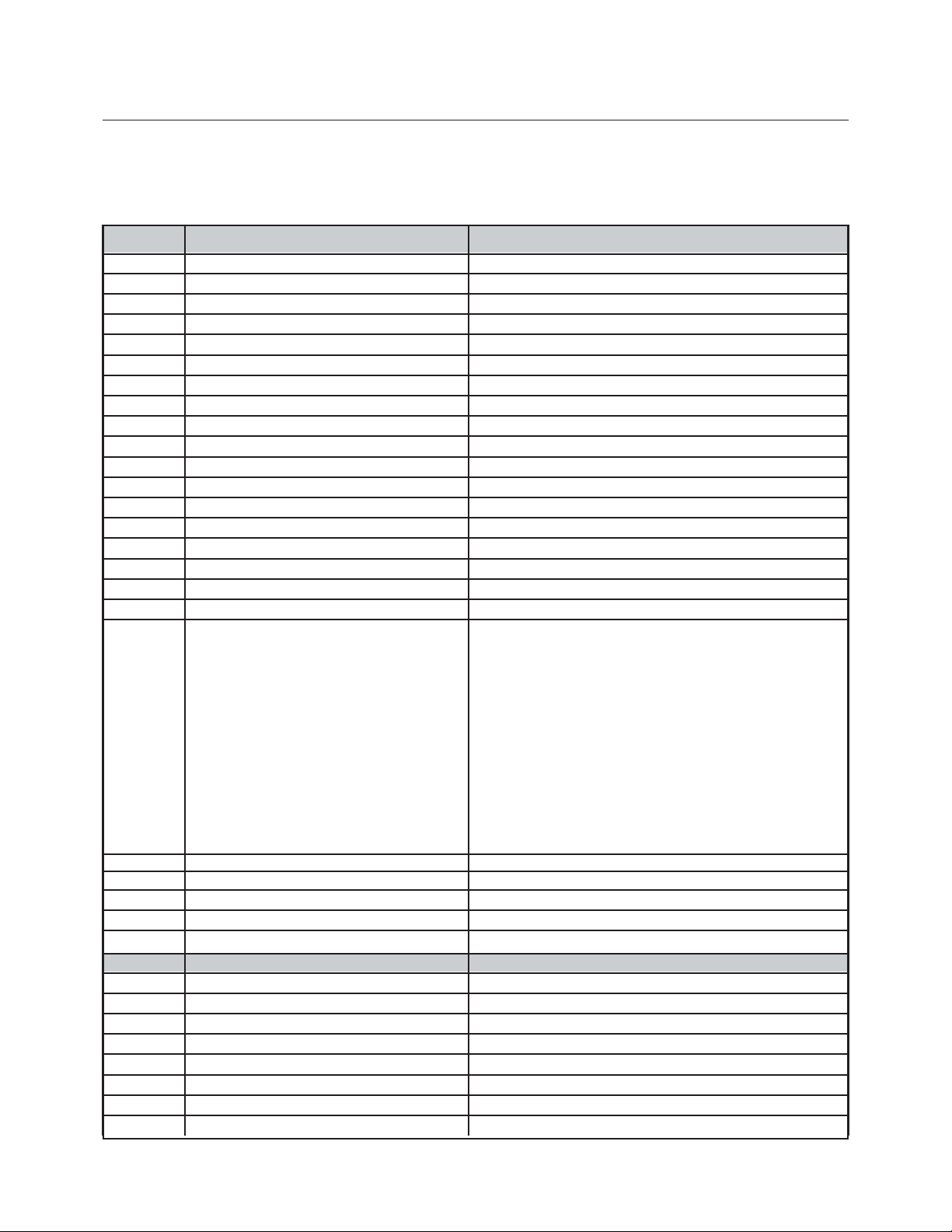
OPERATION COMMANDS (Used for day-to-day operation)
COMMAND OPTIONS OR RANGE DESCRIPTION
A# (0-2) 0=4x3,1=Letterbox, 2=Anamorphic Input Aspect Ratio – for all sources
B# (0-170) 128 default Brightness
C# (0-155) 110 default Contrast
D# (0-13) 8 default Detail
DVI DVI Input
EXT Pass-through Input
FST Report Current System Status
HELP Displays full list of commands for this unit
K# (0-220) 128 default Color
OFF Power OFF
ON Power ON
P# (0-8) [1-8=User, 0=Factory] Recall Profiles
PM# (0-1) [0=Normal1=Bypass] Advanced Color System
PY PassThru Transcoded Input
R RGB input
ST Report Current Status
T# (0-255) 128 default Tint
TP# 0=Off
1=100% Color Bars
2=Reverse Color Bars
3=10-step Grayscale
4=Luma Ramp
5=Cb Ramp
6=Cr Ramp
7=Green
8=Red
9=Blue
10=Convergence
11=Active Boarder
12=Multiburst
13=100% Window
14=PLUGE Test Pattern Selection
TPHELP Display Test Pattern Help
VVideo input
X YCrCb input
Y S-Video input
SETUP COMMANDS (Normally not controlled by RS232)
COMMAND OPTIONS OR RANGE DESCRIPTION
BB# (0-192) Bottom Blanking
BL# (0-252) Border Level – black to white
BLT# (0-255) LCD Backlite Timer on front panel
BLV# 0=0IRE (DEFAULT) , 1 = 7.5 IRE BLACK LEVEL
CR# 0=0-255, 1=16-235 DVI INPUT LEVEL
CS# 1=On 0=OFF Composite Sync – for RGB output
DVD DVI Input Disabled
DHS# 0=NORMAL, 1=WIDE DVI INPUT H SYNC
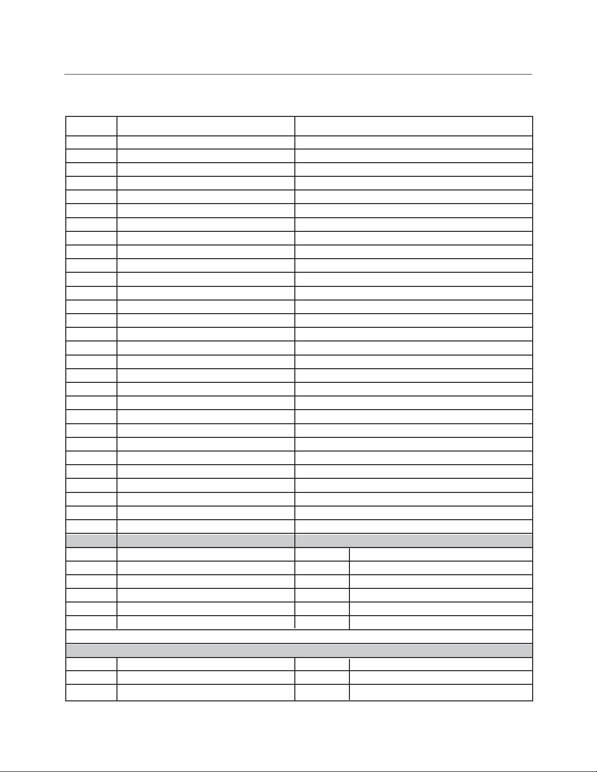
DVE DVI Input Enabler
E# 1=On 0=OFF RS-232 ECHO
EXTD PassThru Input Disabled
EXTE PassThru Input Enabled
HP# (0-50) 25 default Horizontal Position
LB#(0-200) Left Blanking
M# (0-1) [0=RGB, 1=YPrPb] Output Mode
OSDOFF OSD Off – for processor
OSDON OSD On -for processor
OUTMOD 0=Analog, 1=Digital Output Mode
PYD PassThru Transcode Disable
PYE Pass-Thru Transcoder Enabled
RB# 000-192 Right Blanking
RD RGB Input Disabled
RE RGB Input Enabled
SETFT Restore Factory Defaults
STPP# 1-8 Store PAL Profile
STNP# 1-8 Store NTSC Profile
SRNHELP NTSC Scan Rate Help Menu
SRPHELP PAL Scan Rate Help Menu
TB# 000-192 Top Blanking
VD Video Input Disabled
STHELP Setup Help Menu
VE Video Input Enabled
VPOL# (0=Neg 1=Pos) Vsync Polarity
W# 0=4:3, 1=Widescreen, 2=Wide 4:3 Screen Shape
XD YCrCb Input Disabled
XE YCrCb Input Enabled
YD S-Video Input Disabled
YE S-Video Input Enabled
NTSC SCAN RATE LIST USE ONLY BY QUALIFIED TECHNICIAN!
SRN2 1920 x 540 SRN3 800 x 600
SRN4 1280 x 720 SRN5 1024 x 768
SRN6 1280 x 768 SRN7 1366 x 768
SRN8 1440 x 960 SRN9 1280 X 1024
SRN10 DILA SRN11 1400 x 1050
SRN12 1920 x 1080
Note: Enter DVP, FST in a terminal driver program to get the default numbers or contact Faroudja.
PAL SCAN RATE LIST
SRP1 720x576/50Hz SRP4 1024x768/75Hz
SRP2 720x576/100Hz SRP5 1024x768/100Hz
SRP3 1280x720/50Hz SRP6 1920x1080/50Hz
11
RS232 CODES
12
HELP MENUS
DVD OPERATION COMMANDS
DHELP DVD HELP TABLE
PLAY DVD PLAY
STOP DVD STOP
PAUSE DVD PAUSE
EJCT DVD OPEN/CLOSE TOGGLE
DIG# DVD DIGITS 0-9
SETUP DVD SETUP MENU
MENU DVD MOVIE MENU
FU DVD FUNCTION UP
FD DVD FUNCTION DOWN
VL DVD VALUE LEFT
VR DVD VALUE RIGHT
PREV DVD PREVIOUS CHAPTER
NXT DVD NEXT CHAPTER
REW DVD REWIND
FOR DVD FORWARD
RTN DVD RETURN
ENT DVD ENTER
TMENU DVD TOP MENU
STEPP DVD STEP +
STEPN DVD STEP AUD DVD AUDIO
ANG DVD ANGLE
SBT DVD SUBTITLES
DSP DVD DISPLAY
CL DVD CLEAR MEMORY
TEST PATTERN HELP MENU
TPHELP TEST PATTERN HELP MENU
TP0 TEST PATTERN OFF TP1 100% COLOR BARS
TP2 REVERSE COLOR BARS TP3 10 STEP GREY
TP4 LUMA RAMP TP5 CB RAMP
TP6 CR RAMP TP7 BLACK SCREEN
TP8 GREEN SCREEN TP9 RED SCREEN
TP10 BLUE SCREEN TP11 CONVERGENCE
TP12 ACTIVE BORDER TP13 SMPTE PATTERN
TP14 WHITE WINDOW TP15 PLUGE
13
DEFAULT ON-SCREEN-DISPLAY
NTSC Horizontal Vertical
Scan Rate Default Default
852 x 480 25 10
1920 x 540 23 14
800 x 600 14 17
1280 x 720 25 15
1024 x 768 25 17
1280 x 768 22 15
1366 x 768 28 14
1440 x 960 37 10
1280 x 1024 34 20
1365 x 1024 49 19
1400 x 1050 49 19
1920 x 1080 39 4
PAL Horizontal Vertical
Scan Rate Default Default
720 x 576/50 39 17
720 x 576/100 44 17
1280 x 720/50 25 15
1024 x 768/75 39 18
1024 x 768/100 37 18
1920 x 1080/50 40 18
HORIZONTAL AND VERTICAL POSITION
The horizontal and Vertical default position is optimized for each scan rate. Below is the chart of the default numbers
Output Horizontal Vertical
Scan Rate Frequency Frequency
1920 x 540P 33.8 Khz 59.94 Hz
720 x 576P 31.3 Khz 50.00 Hz
720 x 576P 62.5 Khz 100.00 Hz
800 x 600P 37.6 Khz 59.94 Hz
1280 x 720P 45.0 Khz 59.94 Hz
1280 x 720P 37.5 Khz 50.00 Hz
1024 x 768P 60.5 Khz 75.00 Hz
1024 x 768P 80.6 Khz 100.00 Hz
1024 x 768P 48.3 Khz 59.94 Hz
1366 x 768P 48.3 Khz 59.94 Hz
1440 x 960P 62.9 Khz 59.94 Hz
1280 x 1024P 63.9 Khz 59.94 Hz
1365 x 1024P 63.5 Khz 59.94 Hz
1400 x 1050P 64.0 Khz 59.94 Hz
1920 x 1080P 56.3 Khz 50.00 Hz
1920 x 1080P 67.4 Khz 59.94 Hz
14
SPECIFICATIONS
Inputs
Format NTSC
Composite(BNC)
S-Video (4-pin DIN)
Component (BNC)
480i/480p/720p/1080i
RGB (BNC) interlaced
480i/480p/720p/1080i
HD/PC Pass-Thru
DVI Input
Outputs (Progressive)
RGBHV
H&V Sync
YPrPb
RGsB
Digital Video Interface
Digital Audio Connections
Audio Output
Frequency response:
S/N ratio:
Dynamic range:
Total harmonic distortion:
Wow and flutter
Dimensions
(with feet and connectors)
Weight
Power Consumption
Power Supply
1v pp
Y – 1v pp, C – 286mv pp
Y – 1v pp(SMPTE)
Cr – 700mv pp
Cb – 700mv pp
Comp. Sync – 1v pp
RGB – 700mv pp
D15M
DVI – I (female) Digital Only
700mv pp, TTL Sync
2.5v pp@75ohm min.
700mv pp, Sync on Y-1v pp
Gs – 1v pp, RGB – 700mv pp
DVI – I(female) digital only
RCA, BNC, AES/EBU
4 Hz to 44 kHz (DVD fs: 96 kHz)
4 Hz to 88 kHz (DVD-Audio fs: 192 kHz)
118 dB
108 dB
0.001 %
Limit of measurement
(0.001% W. PEAK) or lower
13.5DX17.25WX5.75H
21lbs
50wts/115VAC/60Hz
100 – 240VAC 50/60Hz
Auto Ranging
15
BEFORE YOU START
Disc / Content Format Playback Compatibility
General Disc Compatibility
• This player was designed and engineered to be compatible with software
containing one or more of the following
logos.
DVD-Video DVD-R DVD-RW
Audio CD CD-R
•Other formats, including but not limited
to the following, are not playable in this
player:
Photo CD / DVD-RAM / DVD-ROM /
CD-ROM
(except those that contain MP3 files
formatted as specified in the “Com-
pressed Audio Compatibility” section)
•DVD-R/RW and CD-R/RW discs (Audio
CDs and Video CDs) recorded using a
DVD Recorder, CD Recorder or Personal
Computer may not be playable on this
machine. This may be caused by a
number of possibilities, including but
not limited to: the type of disc used; the
type of recording; or damage, dirt or
condensation on either the disc or the
player’s pick-up lens.
Special note about particular formats or
software follows below:
Video CD
Super Audio CD
CD-RW
CD-R/RW Compatibility
• This unit will play CD-R and CD-RW
discs recorded in CD Audio, Video CD,
or MP3 audio formatting. However, any
other content may cause the disc not to
play, or create noise/distortion in the
output.
• This unit cannot record CD-R or CD-RW
discs.
•Un-finalized CD-R/RW discs recorded in
CD Audio can be played, but not all
Table of Contents (playing time, etc..)
will be displayed.
DVD-R/RW Compatibility
• This unit will play DVD-R/RW discs that
were recorded using the DVD Video
format.
• This unit will play DVD-RW discs that
were recorded using the Video Recording format.
• This unit cannot record DVD-R/RW
discs.
•Un-finalized DVD-R/RW discs cannot be
played in this player.
Compressed Audio Compatibility
• This unit will play compressed audio
files formatted in the MPEG-1 Audio
Layer 3 format (MP3) with a 44.1 or
48kHz fixed bit rate. Incompatible files
will not play and “UNPLAYABLE” will be
displayed on the unit.
•Variable Bit-Rate (VBR) files are
playable, but playing time may not be
shown correctly.
• The CD-ROM used to compile your MP3
files must be ISO 9660 Level 2 compliant.
• CD physical format: Mode1, Mode2 XA
Form1.
• This player only plays tracks that are
named with the file extension “.mp3” or
“.MP3”.
16
BEFORE YOU START
• This player is compatible with multisession discs, but only plays sessions
that are closed.
•Use CD-R or CD-RW media for recording your MP3 files.
• This player can recognize a maximum of
250 folders or 250 tracks. Discs containing more than 250 folders or 250 tracks
will play, but only the first 250 folders /
tracks.
•Folder and track names (excluding the
“.mp3” extension) are displayed.
• There are many different recording bitrates available to encode your MP3 files.
This unit was designed to be compatible
with all of them. Audio encoded at
128Kbps should sound close to regular
CD Audio quality. This player will play
lower bit-rate MP3 tracks, but please
note that the sound quality becomes
noticeably worse at lower bit-rates.
PC Created Disc Compatibility
• If you record a disc using a Personal
Computer, even if it is recorded in a
“compatible format” as listed above,
there will be cases in which the disc
may not be playable in this machine due
to the setting of the application software
used to create the disc. In these
particular incidences, check with the
software publisher for more detailed
information.
•DVD-R/RW and CD-R/RW software disc
boxes also have additional compatibility
information.
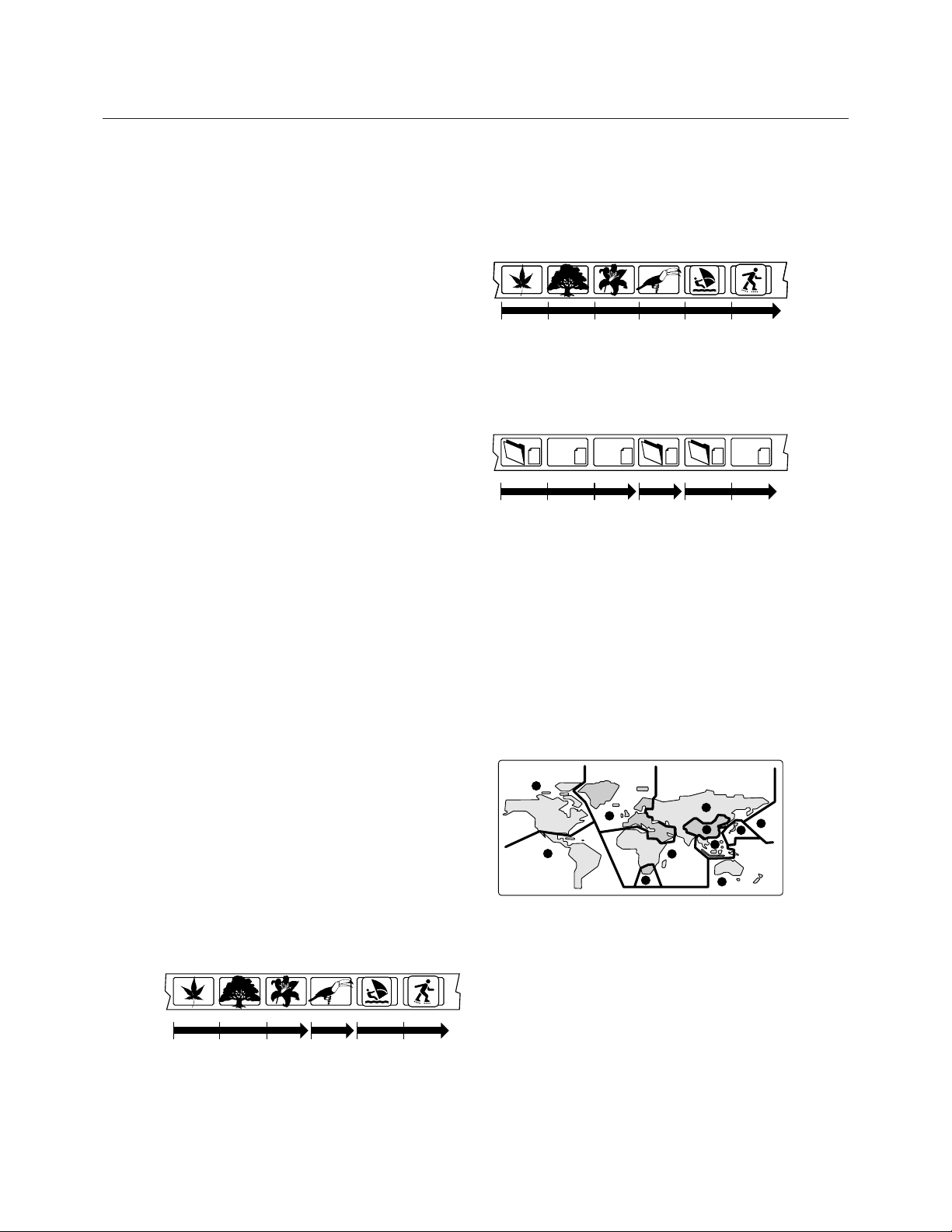
Titles, chapters, Groups and tracks
DVD-Video discs are generally divided into
one or more titles. Titles may be further
subdivided into chapters.
CDs and Video CD are divided into
tracks.
Tr ack 1 Track 2 Track 3 Track 4 Track 5 Track 6
CD-ROMs containing MP3 files are divided
into folders and tracks. Folders may also
contain further subfolders.
mp3
mp3
mp3
mp3
mp3
mp3
Folder A Folder B Folder C
Track 1 Track 2 Track 3 Track 1 Track 1
Track 2
DVD-Video regions
All DVD-Video discs carry a region mark on
the case somewhere that indicates which
region(s) of the world the disc is compatible
with. Your DVD player also has a region
mark, which you can find on the rear panel.
Discs from incompatible regions will not play
in this player. Discs marked ALL will play in
any player.
The diagram below shows the various DVD
regions of the world.
1
2
4
2
5
6
5
1
2
3
4
Title 1 Title 2 Title 3
Chapter 1 Chapter 2 Chapter 3 Chapter 1 Chapter 1 Chapter 2

IR REMOTE FOR DVD
Touch screen page 4 - number
selections
Remote Control
for DVD Transport
Touch screen page 1 - transport controls
PLAY / PAUSE
REWIND / FAST FORWARD
SKIP BACK / SKIP FORWARD
STEP BACK / STEP FORWARD / STOP
Touch screen to access
the different controls
Touch arrows to cycle
through availabel touch screens
Navigation buttons.
Press Up/Down to select functions,
press Left/Right to change values.
Press Enter to execute
a command.
Press Menu to cycle through
the available menu pages.
Touch screen page 3 - menu access
DVD MENU ACCESS / SETUP ACCESS
RETURN TO TOP OF MENU
Touch screen page 2 - extra feature access.
EJECT / RETURN TO MENU
AUDIO OPTION / ANGLE SELECT
SUBTITLE ON-OFF / DISPLAY ON-OFF
CLEAR ENTRY / PLAY OPTIONS
Page 2
Return
Audio Angle
Subtitle Display
Clear
Play
Mode
Page 1
Page 3
Menu Setup
Top
Page 4
123
456
789
10
Press to pauseplayback; press again to restart
Use for reverse/ forward slow motion playback, frame
reverse/ advance and reverse/ forward scanning.
CLEAR
Press to clear a numeric entry
ENTER
Press to select an option or execute a command
(STANDBY/ ON)
Press to switch the player on or into standby
DISPLAY
Press to display information about the disc playing
AUDIO
Press to select the audio channel or language
SETUP
Press to display (or exit) the on-screen display
(RETURN)
Press to return to a previous menu screen
Press to stop the disc (you can resume playback by
pressing (play)
Press to start or resume playback
Press to jump to the start of the previous/next
chapter/track
PLAY MODE
Press to display the Play Mode menu (You can also get
to the Play Mode menu by pressing SETUP and
selecting Play Mode)
MENU
Press to displayh a DVD disc menu, or the Disc
Navigator
if a DVD-RW, CD, Video CD or MP3 disc is loaded
OPEN/CLOSE
Press to open or close the disc tray
ANGLE
Press to change the camera angle during DVD multiangle scene playback
SUBTITLE
Press to select a subtitle display
TOP MENU
Press to display the top menu of a DVD disc
17
 Loading...