

Meridian Link/Customer Controlled Routing, Meridian Link Installation Manual

Meridian 1
Meridian Link/Customer Controlled Routing
Installation and Upgrade Guide
Publication number: 553-3202-210
Product release: Meridian Link Release 5C/Customer Contolled Routing Release 3C
Document status: Standard 1.0
Date: October 1998
© 1998 Northern Telecom
All rights reserved
Printed in the United States of America
Northern Telecom reserves the right to make changes in equipment, design, or components as progress in
engineering or manufacturing may warrant.
Meridian 1, SL-1, and Nortel are trademarks of Northern Telecom. UNIX is a trademark of AT&T. Motorola is a
trademark of the Motorola Corporation. MVME products are trademarked by the Motorola Corporation.
Ethernet is a trademark of the Xerox Corporation. Reflection is a trademark of Walker Richer & Quinn, Inc.
DEC, VT220, VT320, and VT420 are trademarks of Digital Equipment Corporation. UDS is a trademark of
Motorola Incorporated.

ii
553-3202-210 Standard October 1998

Publication history
October 1998
Standard 1.0
iii
Meridian Link Release 5C/CCR Release 3C Installation and Upgrade Guide

iv Publication history
553-3202-210 Standard October 1998

Contents
v
About this guide xv
References xviii
Chapter 1: Meridian Link/CCR 1
Co-residency overview 1
Keycode 4
Ethernet LAN-based PC 5
Module address and module name 7
Chapter 2: Overview of Meridian Link 9
Meridian Link application 13
Operating system overview 13
New with Meridian Link Release 5C 14
Link overview 15
AML and the Host Link (or Meridian Link) 15
Meridian Mail Link 16
Diagnostic tools 16
System console and maintenance console 17
Meridian Link administration and maintenance 17
Host support service requirements 18
Meridian 1 18
Hardware overview 18
Software overview 21
Host 23
Meridian Link service requirements 23
Host connection considerations 24
Ethernet LAN-based host 24
Meridian Mail software requirements 26
Operations, Administration, and Maintenance (OA&M) 26
Meridian Link Release 5C/CCR Release 3C Installation and Upgrade Guide

vi Contents
Chapter 3: Overview of Customer Controlled
Routing 27
CCR application 30
An example of CCR call handling 30
Key CCR concepts 31
Operating system 31
New with CCR Release 3C 32
Application Module Link 32
Diagnostic tools 32
System console and maintenance console 32
CCR administration and maintenance 33
Consoles/printers 33
Meridian 1 34
Hardware overview 34
Software overview 36
Chapter 4: Meridian Link/CCR hardware 39
IPE Module 39
Connector panel and I/O connectors (Option 11) 42
Connector panel and I/O connectors (Options 21Ð81) 45
IPE Module components 46
Application Module 50
AEM power 53
Application Module components 54
Single board computer card (Application Module) 58
MVME333-2 X.25 communication controller (XCC) card 66
MVME332XT or MVME332XTS asynchronous
communication controller (ACC) card 68
Transition cards 70
P2 adapter board 78
Power supply 79
Disk/tape unit 80
VME bus backplane (Application Module) 82
Power sense card (Application Module) 82
I/O connectors (Application Module) 82
Input/output panel 83
553-3202-210 Standard October 1998

Contents vii
Chapter 5: Hardware installation overview 87
Preparing for installation 87
Installing an IPE Module or an Application Module 88
Chapter 6: Site survey/installation checklist 91
General information 91
End user 91
Distributor 92
Nortel support representative 92
Delivery information 93
Customer site 93
Freight company 93
Loading equipment required 94
Meridian 1 software checklists 94
Requirements for Meridian Link 95
Requirements for CCR 97
Requirements for Meridian Mail to support Meridian Link 99
Meridian Mail hardware checklist to support Meridian Link 100
IPE Module and Application Module: Meridian Link/CCR
software 101
IPE Module and Application Module: Meridian Link/CCR
software current status 101
Changes to IPE Module and Application Module 101
Meridian Link/CCR tapes and keycode 102
Documentation 103
Hardware 104
Equipment room information 105
Power and ground considerations 106
Equipment cabling 107
Input/output device cabling 107
Peripheral device cabling 108
Telephony connections 111
Equipment room cooling conditions 112
Additional considerations 112
Comments and recommendations 113
Meridian Link Release 5C/CCR Release 3C Installation and Upgrade Guide

viii Contents
Chapter 7: Unpack and inspect hardware 115
Receiving the IPE Module and Application Module
components 116
Unpacking the IPE Module and Application Module
components 117
Chapter 8: Hardware installation procedures 119
Installing the IPE Module 120
Installing the Application Module 125
Installing the power supply and disk/tape unit 127
Checking the card option settings (Application Module) 129
Installing an NTAK02 SDI/DCH card 142
Installing an ESDI or MSDL card 145
Chapter 9: Meridian Link/CCR interface cabling 151
IPE Module cabling 151
IPE Module cables 151
External I/O cables 154
External I/O cable pinouts (IPE Module) 155
Cabling the Option 11 IPE Module to external equipment 177
Cabling to external equipment 177
Backplane cable rerouting for Options 21Ð81 CE/PE and IPE
backplanes 185
Backplane cable rerouting for the NT8D11 CE/PE Module
backplane 187
Backplane cable rerouting for NT8D37 IPE Module 195
Cabling the Options 21Ð81 IPE Module to external equipment 209
Application Module cabling 216
Power cables 216
Input/output cables 219
Cabling the Application Module to external equipment 227
Installing Ethernet LAN support 256
553-3202-210 Standard October 1998

Contents ix
Chapter 10: Installing peripheral devices 261
VT220, VT320, and VT420 terminals 261
Personal computer running Reflection 4+ 266
Meridian Terminal Emulator (MTE 8) 267
Dot-matrix printer switch settings 268
LaserJet series II printer switch settings 269
LaserJet series III printer switch settings 270
LaserJet series IV printer switch settings 271
DeskJet and DeskJet 500 printer switch settings 272
Chapter 11: Peripheral device cabling interface 273
DCE and DTE connections 273
Using an A/B switchbox to share system consoles 276
Connecting the A/B switchbox 276
Using the A/B switchbox to switch applications 277
Modems 278
Limited-distance modem 278
USRobotics Sportster modem 279
Gandalf LDS 120E limited-distance modem 280
Dial-up modem 282
Chapter 12: Meridian 1 configuration 293
Conventional notation 293
Configuration overview 295
Configuring the VSID, HSID, and AML prompts 296
Configure ESDI port (X11 Release 17) 299
Options 21Ð81 ESDI configuration 299
Enable ESDI port (X81 phase 7 or X11 Release 17) 302
Configure ESDI or MSDL port (X11 Release 18 or later) 305
Option 11 ESDI configuration 305
Option 21Ð81 ESDI or MSDL configuration 308
Enable ESDI or MSDL port (X11 Release 18 or later) 312
Configure SDI port for conshare (X11 Release 17) 315
Configure SDI port for conshare (X11 Release 18 or later) 317
Enable SDI port 318
Configuring DNIS to use auto-terminating trunks 319
LD 15ÑCustomer data block 319
LD 16ÑRoute data block 320
LD 14ÑTrunk data block 322
Configuring DNIS to use Incoming Digit Conversion 324
Meridian Link Release 5C/CCR Release 3C Installation and Upgrade Guide

x Contents
Configure devices for status change host notification 330
Define status message groups 333
Assign telephones to status message groups (Meridian
Link) 335
Configure ACD DNs 344
Configure Control DNs (CCR) 346
Configuring a Phantom Loop 349
Configuring a Phantom Superloop 350
Creating a Phantom Set 351
Configuring Dual VAS ID 353
Traffic statistics 354
Chapter 13: Meridian Mail configuration 355
Meridian Mail call processing 357
Configuring Meridian 1 for Meridian Mail 358
Creating a Meridian Mail ACD queue 358
Defining virtual agent DNs for voice channels 360
Configuring Meridian Mail for Host Enhanced Voice
Processing (HEVP) 363
Adding the Meridian Mail ACD DN to the Voice Service DN
(VSDN) Table 363
Defining voice channels in the Channel Allocation Table
(CAT) 366
Defining a new mailbox for the application 368
Chapter 14: Software installation, upgrade, and
update procedures 371
To configure the software after installing a new IPE Module
or Application Module 375
Section 1: To upgrade Meridian Link from Release 2 to
Release 5C or Co-residency using a Release 2 backup
tape 376
Section 2: To upgrade Meridian Link from Release 3 to
Release 5C or Co-residency using a Release 3 backup
tape 377
Section 3: To upgrade Meridian Link from Release 4 to
Release 5C 378
Section 4: To upgrade Meridian Link from Release 4 to 379
Section 5: To upgrade Meridian Link from Release 4B to
Release 5C 380
553-3202-210 Standard October 1998

Contents xi
Section 6: To upgrade Meridian Link from Release 4B to
Release 5C and Co-residency 381
Section 7: To update Meridian Link from Release 5 to
Release 5C 382
Section 8: To update Meridian Link from Release 5 to 382
Section 9: To upgrade CCR from Release 2 to Release 3C
or 383
Section 10: To update CCR from Release 3 to Release 3C 384
Section 11: To update CCR from Release 3 to Co-
residency 384
Section 12: To update CCR Release 3B to Release 3C 385
sSection 13: To update CCR from Release 3B to Co-
residency 385
Section 14: To update Co-residency from one issue to
another issue of the same release 385
Section 15: Activating or de-activating a Meridian Link or
CCR feature 386
Section 16: To install or reinstall the software from tape 386
Procedure 1: Application configuration and start-up 388
Procedure 2: Start the update process 397
Procedure 3: Load application software from tape 399
Procedure 4: Power down the IPE Module or the
Application Module 411
Procedure 5: Load the operating system tape on an
Application Module with an MVME147 card 413
Procedure 6: Load the operating system tape on an IPE
Module or an Application Module with an MVME167
card 429
Procedure 7: Reboot and go through setup 448
Procedure 8: Load the application software from tape 458
Procedure 9: Restore configuration files and data files from
the backup tape 471
Procedure 10: Verify the installation 475
Procedure 11: Back up configuration files and data files 476
Meridian Link Release 5C/CCR Release 3C Installation and Upgrade Guide

xii Contents
Chapter 15: Link configuration 479
Default configuration 479
Link 0ÑApplication Module Link 479
Link 1ÑX.25 protocol 480
Link 1ÑTCP/IP host link protocol 481
Link 2ÑMeridian Mail Link 481
Changing your configuration 482
Procedure 12: Verifying the link status 483
Procedure 13: Changing AML (link 0) parameters 484
Procedure 14: Changing Meridian Link (link 1) parameters 489
Procedure 15: Changing Meridian Mail Link (link 2)
parameters 497
Procedure 16: Replacing the default configuration file 499
Procedure 17: Creating a configuration file 500
Chapter 16: Additional application configuration503
Procedure 18: Turn off auto-start 505
Procedure 19: Change the Meridian 1 customer number 506
Procedure 20: Schedule regular backups 507
Procedure 21: Change the default system languages 509
Procedure 22: Configure terminal ports 511
Procedure 23: Configure printer ports 513
Chapter 17: Hardware upgrade 517
To upgrade an Application Module SBC card from an
MVME147 card to an MVME167 card 517
To upgrade an Option 11 IPE Module to an Options 21Ð81
IPE Module 517
Procedure 24: Software powerdown 518
Procedure 25: Hardware powerdown 520
Procedure 26: Upgrading the Application Module from an
MVME147 card to an MVME167 card 521
Procedure 27: Upgrading an Option 11 to an Options
21Ð81 IPE Module 522
Procedure 28: Installing the cables for Ethernet LAN
support (Application Module) 524
Procedure 29: Installing the MVME332XT or
MVME332XTS ACC card 526
553-3202-210 Standard October 1998

Contents xiii
Chapter 18: Acceptance testing 527
Meridian Link/CCR 527
Meridian Mail 529
Using Edit Voice to create voice segment files 529
Recording and trimming voice segments 530
Creating a header file 530
Using Edit Voice for the first time 531
Example of customer account balance query 531
Chapter 19: Single Terminal Access 533
Hardware and software requirements 533
Before you begin 534
Setting up STA 537
Chapter 20: Ordering 545
List of terms 553
Index 559
Meridian Link Release 5C/CCR Release 3C Installation and Upgrade Guide

xiv Contents
553-3202-210 Standard October 1998

About this guide
This document details the steps and procedures required to successfully
install the hardware and software for your Meridian Link and/or Customer
Controlled Routing (CCR) system.
Meridian Link enables the call and voice processing capabilities of a
Meridian 1 system to be integrated with a customerÕs computer-based
business applications. Through Meridian Link, an application can place and
answer calls, route calls, and even implement Interactive Voice Response
applications.
CCR enables you to control and route Automatic Call Distribution (ACD)
calls entering your Meridian 1 system. For example, for an incoming ACD
call, you can provide a specific recorded announcement, music, or both,
before assigning the call to an agent.
The hardware for both applications can be either an Intelligent Peripheral
Equipment (IPE) Module or an Application Module.
xv
The software consists of a base operating system (BOS) and application
programs, referred to as the Meridian Applications.
This guide contains the following main areas of information:
Chapter 1: Meridian Link/CCR co-residency The first chapter provides an
overview of Meridian Link/CCR co-residency and describes the keycode
and the Ethernet LAN-based PC features.
Chapter 2: Overview of Meridian Link This chapter provides an overview
of Meridian Link, describes its concepts, and lists required hardware and
software.
Meridian Link Release 5C/CCR Release 3C Installation and Upgrade Guide

xvi About this guide
Chapter 3: Overview of Customer Controlled Routing This chapter
provides an overview of CCR, describes its concepts, and lists required
hardware and software.
Chapter 4: Meridian Link/CCR hardware This chapter provides an
overview of hardware components.
Chapter 5: Hardware installation overview This chapter lists the tools and
provides tables to describe the installation of an IPE Module or an
Application Module.
Note: If you intend to install an IPE Module or an Application
Module, refer to Table 11 (IPE Module) or Table 12 (Application
Module) in this chapter.
Chapter 6: Site survey/installation checklist This chapter provides a
checklist to ensure that all hardware and software requirements are met for a
successful installation.
Chapter 7: Unpack and inspect hardware This chapter provides
information on receiving, unpacking, and inspecting the IPE Module and
Application Module hardware components.
Chapter 8: Hardware installation procedures This chapter contains all of
the main hardware installation procedures, with references to surrounding
chapters for further information.
Chapter 9: Meridian Link/CCR interface cabling This chapter describes
the cabling requirements. Two following chapters describe how to set up
terminals, and how to configure the Meridian 1 system.
Chapter 10: Installing peripheral devices This chapter describes the
procedures for how to set up and configure video display terminals and
printers supported by the Meridian Link and CCR appplications.
Chapter 11: Peripheral device cabling interface This chapter provides
information on installing and configuring modems and the A/B switchbox.
Chapter 12: Meridian 1 configuration for Meridian Link/CCR This
chapter shows how to use various software programs to configure the
Meridian 1 to support Meridian Link and CCR.
553-3202-210 Standard October 1998

About this guide xvii
Chapter 13: Meridian Mail configuration This chapter shows how to
configure the Meridian 1 to support Meridian Mail.
Chapter 14: Software installation, upgrade, and update procedures
This chapter describes procedures for
¥ configuring the IPE Module and the Application Module, along with
start-up information
¥ upgrading the software from one release to another (for example, from
Meridian Link Release 4B to Release 5C)
¥ updating the software from one issue of a release to another issue of the
same release (for example, from issue 4.17 to issue 4.25)
¥ reinstalling software (for example, after replacing a hard disk)
Chapter 15: Link configuration This chapter describes the configuration
procedures for the links used by the applications.
Chapter 16: Additional application configuration This chapter describes
the procedures used for scheduling backups and configuring terminal and
printer ports.
Chapter 17: Hardware upgrade This chapter describes the procedures for
upgrading from an MVME147 card to an MVME167 card and upgrading an
Option 11 IPE Module to an Options 21Ð81 IPE Module.
Chapter 18: Acceptance testing This chapter describes the various
acceptance tests you can perform.
Chapter 19: Single Terminal Access This chapter describes how to
configure the Meridian 1 system to support Single Terminal Access.
Chapter 20: Ordering This chapter lists field-replaceable items for both the
IPE Module and Application Module.
Note: The term ÒMeridian 1Ó is used throughout this document, and
refers to Meridian 1 and ÒMeridian 1-readyÓ systems (such as Meridian
SL-1 style cabinets that have been upgraded).
Meridian Link Release 5C/CCR Release 3C Installation and Upgrade Guide

xviii About this guide
References
Refer to the following related documents:
¥ Application Equipment Module Installation Guide (NTP 553-3201-200)
¥ Application Module and Intelligent Peripheral Equipment Module
¥ Application Module and Intelligent Peripheral Equipment Module
¥ Meridian Link/Customer Controlled Routing Engineering Guide
¥ Customer Controlled Routing User Guide (P0747008)
Diagnostic and Maintenance Guide (NTP 553-3211-510)
Advanced Maintenance Guide (NTP 553-3211-512)
(NTP 553-3211-520)
553-3202-210 Standard October 1998

Chapter 1: Meridian Link/CCR
co-residency
Co-residency overview
With Meridian Link Release 5C and CCR Release 3C, you can install both
Meridian Link and CCR in a single IPE Module or Application Module.
You should be aware that both applications use the same CPU, RAM, and
hard disk, so you cannot expect the same performance from a
co-resident application as you would get from a stand alone application.
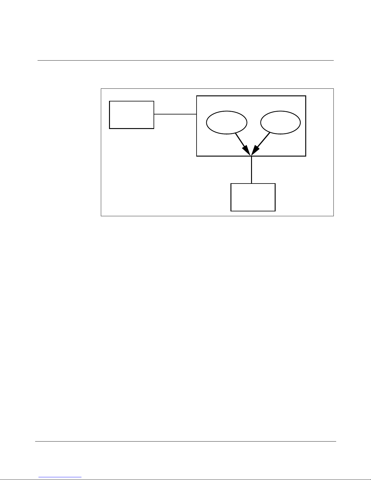
As shown in Figure 1, Meridian Link and CCR applications communicate
with the Meridian 1 through the same Application Module Link (AML), and
at the same time.
1
Meridian Link Release 5C/CCR Release 3C Installation and Upgrade Guide
2 Chapter 1: Meridian Link/CCR co-residency
Figure 1
Meridian Link/CCR co-residency
Host
Host Link
IPE Module
Meridian
Link
Meridian 1
CCR
AML
553-3202-210 Standard October 1998

Chapter 1: Meridian Link/CCR co-residency 3
This guide provides more detailed information on both the Meridian Link
and CCR applications in the following chapters:
¥ Chapter 2, ÒOverview of Meridian LinkÓ
¥ Chapter 3, ÒOverview of Customer Controlled RoutingÓ
If you intend to activate both Meridian Link and CCR in an Application
Module, the Application Module must have an MVME332XTS ACC card
and an NT6D51AA transition card installed. Refer to Chapter 4, ÒMeridian
Link/CCR hardwareÓ for descriptions of these cards.
If you intend to activate both Meridian Link and CCR in an IPE Module,
you should know that only two ports (7 and 8) will be available for CCR
terminals or printers. Port 6 will be used for the Host Link. However, you
can use LAN-based PCs as additional terminals. For more information, refer
to ÒEthernet LAN-based PCÓ later in this chapter.
Note: If you expect the maximum number of active CDN script
associations at any one time to be 20 or fewer, you should consider
installing CCR-S instead of the larger version (Large CCR). By doing
so, you will enhance the processing power available to Meridian Link
and CCR. Large CCR accommodates as many as 240 active CDN
script associations at any one time.
For more information about Meridian 1 configuration changes for coresident systems, refer to ÒConfiguring the VSID, HSID, and AML
promptsÓ in Chapter 12, ÒMeridian 1 Configuration for Meridian
Link/CCR.Ó
Meridian Link Release 5C/CCR Release 3C Installation and Upgrade Guide

4 Chapter 1: Meridian Link/CCR co-residency
Keycode
IPE or Application Module software may or may not be pre-loaded:
¥ If the module is shipped to the United States, Europe, or Japan, the
software is likely to be already loaded.
¥ If the module is shipped to a Caribbean or Latin American location, to
Canada, or to the Asia Pacific region, the software may not be loaded.
If the software is preinstalled, a special keycode activates only the ordered
application or applications during installation. When the module is installed
at your site, you must enter a keycode to activate the correct application or
applications before you can configure the new module. You also need a
keycode anytime you upgrade to a new software release.
A keycode consists of 20 alphanumeric characters divided into five groups
of four characters each. This keycode is obtained from Northern Telecom
and defines the features and hardware configuration purchased by the
customer. A keycode label is attached to your application tape, and a label
is provided as a loose item. If you require new features or capacities, you
must obtain a new keycode.
In each system operation, the software prompts the operator for the
appropriate group of alphanumeric characters within the keycode necessary
to perform that operation. Keycodes are matched to serial numbers, and
only one keycode is necessary to perform multiple system operations. The
system software compares the parameters that the keycode defines with the
new configuration and the serial number during a system operation. If an
exact match is not found, the keycode will not work and will be rejected.
If the keycode is rejected, you may reenter the keycode (if it was entered
incorrectly) or reboot the system into service, because the system has not
been altered during the attempt to use the rejected keycode. However, if a
keycode is rejected during conversion, you must either complete the
operation or restore the old operating system. For more information, refer to
Chapter 14, ÒSoftware installation, upgrade, and update procedures.Ó
553-3202-210 Standard October 1998

Ethernet LAN-based PC
Meridian Link and CCR co-residency also provides support for an Ethernet
LAN-based PC. This networking service is included for all Meridian Link
and CCR customers.
Note: Support for an Ethernet LAN-based PC should not be confused
with support for an Ethernet LAN-based host. For more information on
Ethernet LAN-based host connections, refer to ÒEthernet LAN-based
hostÓ in Chapter 2, ÒOverview of Meridian Link.Ó
This feature allows users to log in to an IPE Module or Application Module,
and work with CCR scripts or perform OA&M tasks remotely from a PC.
To use this feature, a local area network (LAN) must be installed between
the Ethernet LAN-based PC and the Meridian Link/CCR IPE Module or
Application Module. Each node must have the Network Service Extension
(NSE) software running to provide TCP/IP (Transmission Control
Protocol/Internet Protocol) service.
Chapter 1: Meridian Link/CCR co-residency 5
Although this feature is designed to meet CCR requirements, it provides a
networking option for the Meridian Link application. With the minimum
configuration offered by Northern Telecom, Meridian Link customers may
use the Ethernet LAN-based PC to perform administrative tasks remotely.
The Ethernet LAN-based PC connection is compatible with IEEE802.3
Ethernet Standards and Ethernet II Standards using 10-based T, 10-based 2,
10-based 5, and fiber optics.
Ethernet support is automatically enabled during application installation. All
NSE files will be loaded to the hard disk, but only those customers who
purchased the service option will be able to configure the NSE. To
configure the NSE, see Procedure 8 in Chapter 14, ÒSoftware installation,
upgrade, and update procedures.Ó
Note: If you do not intend to provide an Ethernet LAN-based PC on
your system, you should disable this support during application
installation (you do this by entering the appropriate keycode). By
disabling LAN-based PC support, you increase the processing power
available to Meridian Link and CCR.
Meridian Link Release 5C/CCR Release 3C Installation and Upgrade Guide

6 Chapter 1: Meridian Link/CCR co-residency
The Ethernet LAN-based PC must
¥ be fully compatible with an IBM PC (AT or higher)
¥ have a 20-Mbyte hard disk or larger
¥ have 1 Mbyte of RAM with at least 384 Kbytes free
¥ contain an Ethernet LAN adapter card that is ODI, NDIS, ASI, or
packet driver compatible
¥ have a VGA or EGA color monitor and card with at least a 256-Kbyte
buffer
The PC must contain
¥ Microsoft MS-DOS, Version 5.0 or higher
¥ FTP Software Inc.Õs PC/TCP for DOS 2.05 or higher
In addition, the PC must contain one of the following terminal emulation
packages:
¥ Walker, Richer & Quinn Inc.Õs Reflection 2 for Windows (version 4.11
or later) with Telnet Connect for PC (version 1.1 or later)
¥ FTP Software Inc.Õs Wtnvt program (version 2.3 or later)
¥ Wollongong GroupÕs Pathway Access for Windows 3.0
Note: Windows applications also require Microsoft Windows; refer to
the Windows application for the version required.
Northern Telecom has tested and supports the following LAN adapter cards:
¥ 3COM Etherlink II/MC
¥ 3COM Etherlink II
¥ 3COM Etherlink III
Other cards supported by FTP Software Inc.Õs PC/TCP Kernel for DOS 2.05
or higher and compliant with Industry Standard Open Driver Specifications
may also work.
553-3202-210 Standard October 1998

Chapter 1: Meridian Link/CCR co-residency 7
For Ethernet LAN support, Application Modules must contain:
¥ an MVME167-02 SBC card
¥ an MVME712M transition card
¥ a generic I/O panel
¥ NT7D47DA and NT7D47EA cables
For more information about installing the NT7D47DA and NT7D47EA
cables, refer to Procedure 28: Installing the cables for Ethernet LAN support
(Application Module) in Chapter 17, ÒHardware upgrade.Ó
For more information about the MVME167-02 card, the MVME712M
transition card, and the generic I/O panel, refer to Chapter 4,
ÒMeridian Link/CCR hardware.Ó
If an IPE Module or an Application Module is removed from the network,
the remaining modules and PCs that used to have access must be informed
of the disconnection. How to remove the IPE Module or Application
Module entry from the accessing database depends on the TCP/IP software
used on the PC.
When you disconnect the IPE Module or Application Module from the
network, you must use the maint command stopNSE to disable the NSE
software, or error messages will appear on the system console.
Module address and module name
Meridian Link allows a personal computer connected to an Ethernet LAN to
be used as a maintenance terminal for an IPE Module or Application
Module also connected to the LAN. To use this feature, you must tell
Meridian Link
¥ where the IPE Module or Application Module is located in the network
(the module address)
¥ how the IPE Module or the Application Module can be identified (the
module name)
Meridian Link Release 5C/CCR Release 3C Installation and Upgrade Guide

8 Chapter 1: Meridian Link/CCR co-residency
The module address is a 4-byte (32-bit) address expressed as four decimal
numbers separated by dots (such as 123.45.68.8). The module name can
have as many as eight alphanumeric characters.
See your network administrator for more information on creating a module
address and a module name.
553-3202-210 Standard October 1998

Chapter 2: Overview of Meridian Link
Meridian Link is an application that allows a Meridian 1 system to
exchange information with a host computer so that users can integrate the
capabilities of both into a business application. An order desk clerk, for
example, can see information about an incoming call (for example, the
callerÕs name, address, and calling history) on a computer screen while the
telephone is still ringing.
An optional connection to a Meridian Mail system enables the host to
control voice-processing applications. For example, the host application can
intercept a call and ask the caller for information before routing the call to
the appropriate order desk.
Principal hardware components used by Meridian Link are
¥ a Meridian 1 system
9
¥ a computer or network of computers that runs the business application
¥ an Intelligent Peripheral Equipment (IPE) Module or an Application
Module, which contains the Meridian Link application
¥ (optionally) a Meridian Mail system, to provide voice processing if
required
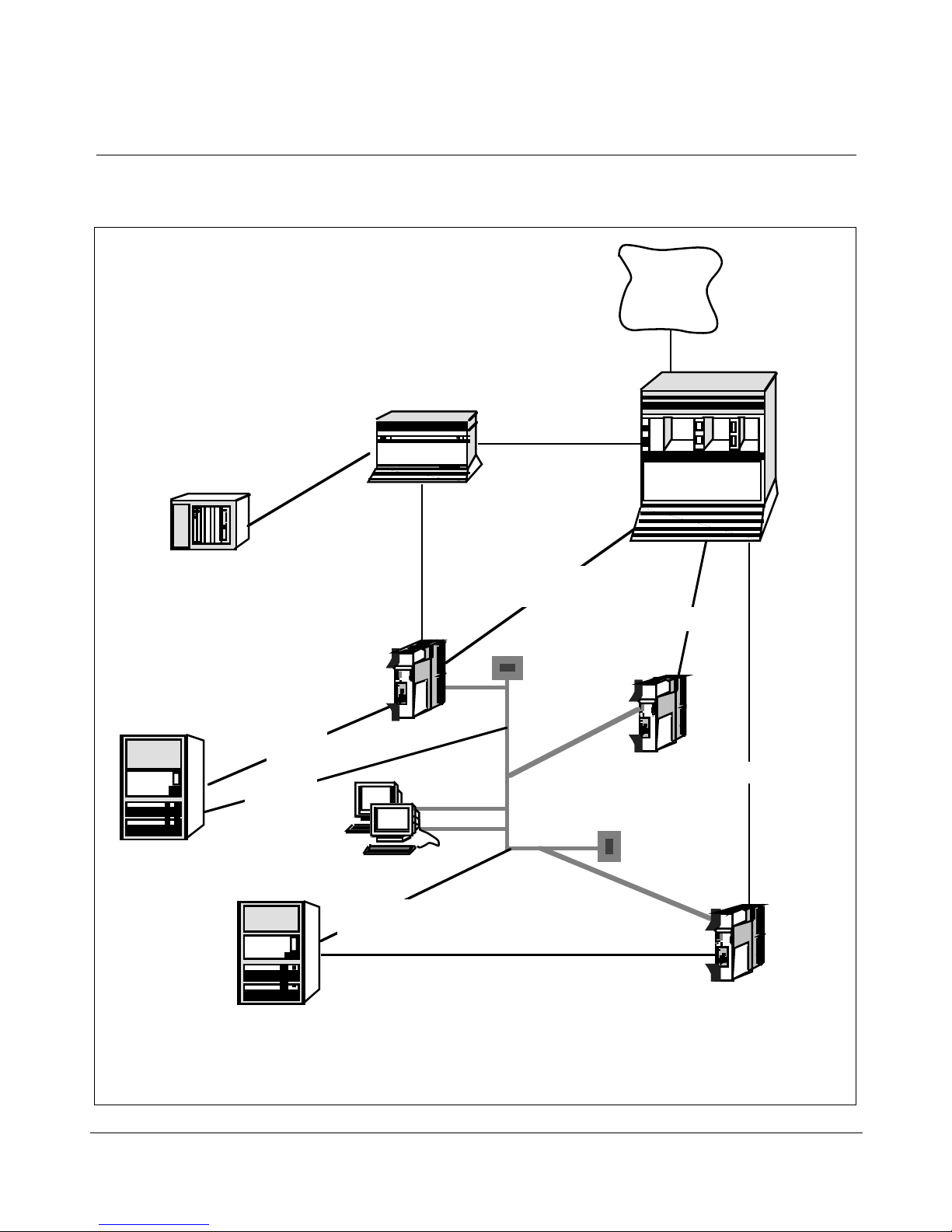
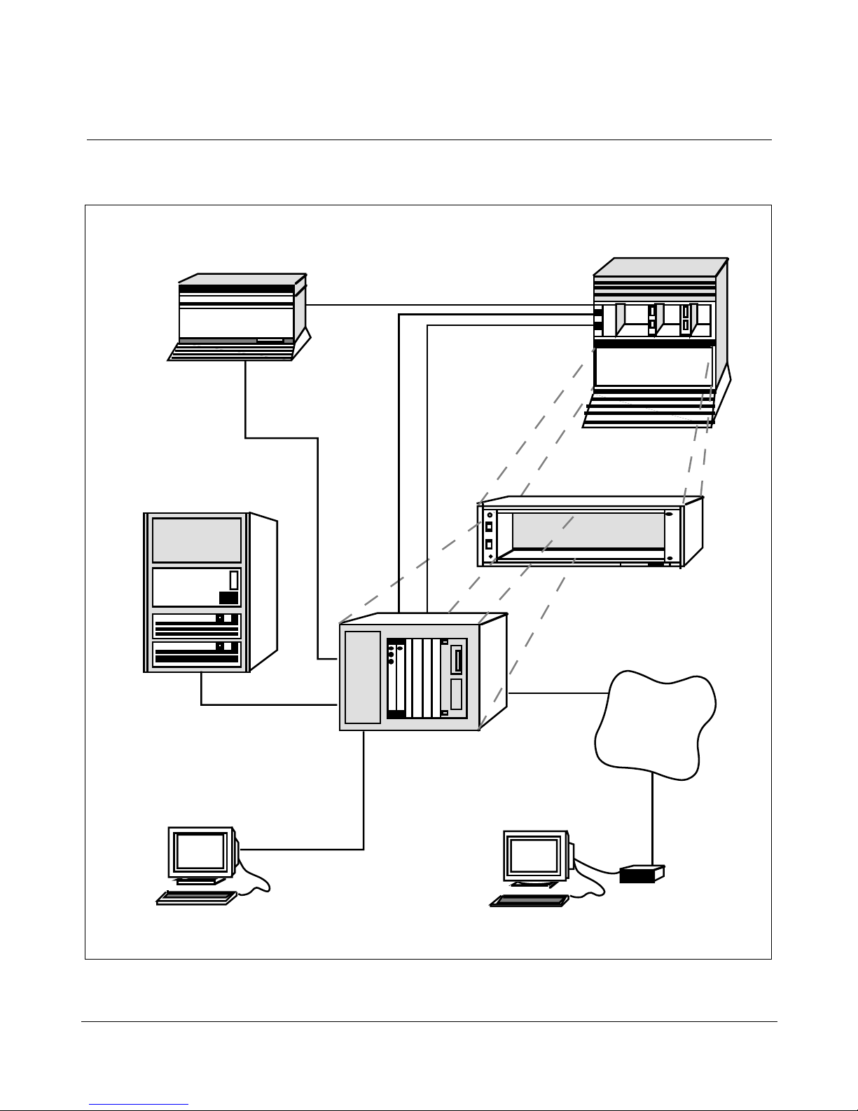
Figure 2 shows the hardware components for an IPE Module, while
Figure 3 shows the hardware components for the Application Module.
Meridian Link Release 5C/CCR Release 3C Installation and Upgrade Guide
10 Chapter 2: Overview of Meridian Link
TP
TP
Figure 2
Meridian Link hardware connections (IPE Module)
Telephone
Network
Meridian 1
Universal
Equipment
Module (UEM)
Meridian IVR
AM
IPE Module (or AM)
Host Link
Host Link
(TCP/IP)
Meridian Link
(X.25)
Meridian Mail
Meridian Mail
Link (MML)
TP
Command and
Status Link (CSL)
Application Module
Link (AML)
Ethernet
(LAN)
Meridian Link/CCR
Co-residency
IPE Module (or AM)
AML
AML
Host computer
Remote system console
Host computer
553-3202-210 Standard October 1998
Host Link
(TCP/IP)
Host Link (X.25)
Redundant
Meridian Link/CCR
Co-residency
IPE Module (or AM)
Chapter 2: Overview of Meridian Link 11
Figure 3
Meridian Link hardware connections (Application Module)
Meridian Mail
Command and
Status Link (CSL)
Meridian 1 Universal
Equipment Module (UEM)
Meridian Mail
Link (MML)
Host computer
Meridian Link
(X.25 or TCP/IP)
Application
Module Link
(AML)
Meridian Link
optional
Meridian 1
OA&M access
Application Equipment
Module (AEM)
to optional
modem
Telephone
network
Module
System console Remote
Meridian Link Release 5C/CCR Release 3C Installation and Upgrade Guide
Modem
system console

12 Chapter 2: Overview of Meridian Link
Connecting these hardware components requires two (optionally three)
signaling links:
¥ Link 0 is an Application Module Link (AML), which connects the
Meridian 1 system to the IPE Module or the Application Module.
¥ Link 1 is a Host Link (or Meridian Link), which connects the host
computer to the IPE Module or the Application Module. This Host Link
can be implemented as a dedicated X.25 link supporting a single host
computer or as a TCP/IP Ethernet LAN link supporting as many as 16
Meridian Link applications.
Note 1: If both the Meridian Link (using TCP/IP) and CCR
applications are running, the Meridian Link third-party application can
support only up to 15 Meridian Link applications.
Note 2: Any mlusr administration sessions requiring association IDs
will reduce the number of association IDs available for Meridian Link
applications. For example, if your system has eight association IDs
registered to Meridian Link applications and then you register two
association IDs for mlusr administration, your system will have six
association IDs available (five, if CCR is running).
Note: If you have registered all 16 association IDs (15 if CCR is
running) to Meridian Link applications, two overflow association IDs
are available for mlusr administration only.
¥ Link 2 is (optionally) a Meridian Mail Link (MML), which connects a
Meridian Mail system to the IPE Module or the Application Module.
In addition, the IPE Module and the Application Module provide an
interface for a system console, which enables you to perform administration
and maintenance. A port that is designed to be connected to a modem
allows you to perform these activities from a remote location.
The key software required to make these hardware components and links
work together is the Meridian Link application, which resides in the IPE
Module or Application Module.
553-3202-210 Standard October 1998
 Loading...