

Page 1
G68 Digital Surround Controller
Installation Guide
Page 2
i i
P r e f a c e
Important safety instructions
• Read the instructions.
• Keep these instructions.
• Follow all instructions.
• Do not use this apparatus near water.
• Clean only with a dry cloth.
• Install only in accordance with the manufacturer’s instructions.
• Refer all servicing to approved service personnel.
WARNING: TO REDUCE THE RISK OF FIRE OR ELECTRIC SHOCK,
DO NOT EXPOSE THIS APPARATUS TO RAIN OR MOISTURE.
This apparatus has been designed with Class 1 construction and
must be connected to a mains socket outlet with a protective
earthing connection (the third grounding pin).
This apparatus uses a single-pole power switch. As a result it is
not isolated from AC mains power when switched off at the rear
panel. The apparatus may be isolated from mains power either by
unplugging the power connector from the rear of the unit, or by
unplugging the connector at the opposing end of the power cord
or cable from its supply outlet. As a result, either or both of these
connectors should remain accessible
Safety warnings
• Do not expose the product to dripping or splashing.
• Do not place any object filled with liquid, such as a vase, on the
product.
• Do not place naked flame sources, such as lighted candles, on the
product.
To avoid overheating
• Leave at least 10cm around the equipment to ensure sufficient
ventilation.
Do not position the product:
• In direct sunlight.
• Near heat sources, such as a radiator.
• Stacked with any other audio products, as the heat it generates
may damage the other products.
• On a soft surface, such as a carpet, which would obstruct the
ventilation holes in the base.
The product normally runs warm to the touch.
Radio interference
FCC Warning: This equipment generates and can radiate radio
frequency energy and if not installed and used correctly in
accordance with our instructions may cause interference to radio
communications or radio and television reception. It has been type-
tested and complies with the limits set out in Subpart J, Part 15 of
FCC rules for a Class B computing device. These limits are intended
to provide reasonable protection against such interference in home
installations.
EEC: This product has been designed and type-tested to comply
with the limits set out in EN55013 and EN55020.
To avoid interference
Do not position the product:
• Near strong magnetic radiation, such as near a power amplifier.
• Near to a television, or where connecting cables may be subject
to or cause interference.
Page 3

i i i
Contents
Introduction 1
Provides information about the digital surround controller
models, a description of each product, and technical
specifications.
Specifications
Installing the digital surround
controller 5
Describes how to install the digital surround controller and
connect it to the other equipment in the system.
Unpacking 5
Audio inputs 6
Audio outputs 10
Tuner and communications connections 16
Configuring the digital surround
controller 19
Explains how to configure the digital surround controller
using the front-panel controls.
Configuration Wizard 19
Stage 1: Resetting the product 20
Stage 2: Configuring speakers 22
Stage 3: Configuring sources 24
DSP presets 37
Gives details of the DSP presets and their parameters, and
describes how to modify them.
DSP presets 37
3
Defining your own presets 47
Troubleshooting 49
Provides suggested solutions to problems while installing,
configuring, or operating the product.
Maintenance 53
Service and guarantee 54
Index 55
C o n t e n t s
Calibrating the system 29
Describes how to fine-tune the digital surround controller
to achieve the optimum performance from your sources and
speaker layout.
Introduction 29
Calibration tests 31
Speaker size 33
Using the Sine/Sub/Sens controls 34
Page 4

i v
P r e f a c e
Copyright and acknowledgements
Sales and service in the UK
Meridian Audio Ltd
Latham Road
Huntingdon
Cambridgeshire
PE29 6YE
England
Tel +44 (0)1480 445678
Fax +44 (0)1480 445686
World Wide Web – http://www.meridian-audio.com/
Copyright © 2003-2010 Meridian Audio Ltd
Designed and manufactured in the UK by Meridian Audio
Ltd. Meridian Audio reserves the right to make changes and
improvements to any of the products described in this document
without prior notice.
Dolby, Dolby Digital, Pro Logic, AC-3, PLII, PLIIx, AAC, and the
double-D symbol are trademarks of Dolby Laboratories Licensing
Corporation. Lucasfilm, THX, and THX Cinema are registered
trademarks of Lucasfilm Ltd. Surround EX is a jointly developed
technology of THX and Dolby Laboratories, Inc and is a trademark
of Dolby Laboratories, Inc. All rights reserved. Used under
authorisation. DTS is a registered trademark of Digital Theatre
Systems Inc. MPEG is a registered trademark of the MPEG
organisation. Ambisonic is a registered trademark of Nimbus
Records Ltd. Trifield is a trademark of Trifield Productions Ltd.
LaserDisc is a trademark of Pioneer Electric Corp.
Sales and service in the USA
Meridian America Inc
8055 Troon Circle
Suite C
Austell
GA30168-7849
USA
Tel +1 (404) 344 7111
Fax +1 (404) 346 7111
This guide was produced by Human-Computer Interface Ltd,
http://www.interface.co.uk/
Manufactured under license from Dolby Laboratories, Lucasfilm Ltd.
(US patents 5,043,970;5,189,703;5,222,059. European patent
0323830), Trifield Productions Ltd, and Nimbus Records Ltd.
MHR: This product incorporates patented copyright protection
technology and intellectual property of Meridian Audio Ltd.
This technology is provided for the express purpose of securely
containing copyright audio within the Meridian System only.
Reverse engineering or circumvention of this protection is strictly
prohibited.
Boothroyd|Stuart Meridian, Meridian, Meridian Digital Theatre, and
Sooloos are registered trademarks of Meridian Audio Ltd.
Part no: GSC/5 (P89569)
Page 5
Introduction
This guide provides full information about unpacking the G68 Digital Surround Controller,
connecting it to the other equipment in the system, and configuring it using the front panel.
Once you have connected and configured the product, refer to the
information about operating it.
G Series System Guide
for
1
I n t r o d u c t i o n
The G68 is a powerful, flexible surround controller, and represents
the centrepiece of the G Series range. It provides eight balanced
analogue outputs, eight digital outputs, component video
switching, and Meridian Room Correction.
At the heart of the G68 is a powerful DSP engine consisting of five
Motorola 56367s running at 150MHz – delivering an incredible
750MIPS (million instructions per second) capability. Processing
is performed at high sample rates and with 48-bit precision
throughout, ensuring that all filtering, processing, and other
operations are carried out beyond the limits of human hearing. The
G68 is thus a perfect processor for the very latest in digital audio.
Inputs
Analogue signals are converted via a 24-bit Delta-Sigma converter
to high-sample-rate digital on input to the processor, while all
digital signals are reclocked to minimise jitter and maintain total
data integrity. The G68 includes two six-channel S/PDIF digital
inputs (coax), a USB audio input, four stereo TOSlink optical inputs,
and six more stereo coax digital inputs. In addition, there is a six-
channel analogue input, and five stereo analogue inputs.
Formats supported
The G68 combines controller and surround processor functions,
meeting the latest THX specifications and including MPEG, DTS,
Dolby, Trifield, and Ambisonic decoding. In many cases the decoders
incorporate our own code, giving them superior integration with
the Meridian design philosophy, as well as superior performance.
As a result, the G68 can decode surround signals from all PCM
optical discs. The G68 is thus an ideal complement to a G Series
optical disc player like the G96.
Page 6

I n t r o d u c t i o n
2
Smart Source feature
The G68’s ’Smart Source’ feature continually monitors the digital
inputs and automatically loads the correct decoding software for
the format, speaker layout, and encoding of the incoming signal.
This capability is enhanced by MHR SmartLink, which provides
a digital link between a Meridian optical disc player or HD621
and surround controller, carrying explicit information about the
nature of the datastream as well as encrypted high-resolution
digital signals from DVD-Audio – the first system of its kind to
be approved. Virtually all other manufacturers oblige you to go
through an analogue connection, losing quality in the process.
You can also store separate parameters for each source (such
as DVD) depending on whether the incoming signal is stereo or
surround, so that any source material is played with the decoder of
your choice.
Meridian Room Correction
The G68 incorporates Meridian Room Correction, a unique system
that compensates for acoustic deficiencies in your listening room,
particularly at the bass end. It achieves this by automatically
analysing the room response and then using powerful Digital
Signal Processing (DSP) technology to build a set of filters, called a
profile. This audibly improves the sound by eliminating resonances
and making the decay time consistent for frequencies below about
250Hz.
Multi-zone capabilities
The G68 provides multi-zone/recording features, consisting of
stereo digital and analogue outputs providing independent sources
to two additional zones. Meridian communications (DIN and
BNC) are also included along with RS232 and USB serial ports for
maintenance and control, an infra-red sensor input, and up to three
12V triggers.
Integral tuner
The G68 includes an integral tuner which provides AM (LW/MW)
and FM (VHF stereo Band II) reception and is fitted with its own
A/D stage. Digital signal processing provides a sophisticated FM
stereo blend/width control which allows the user to minimise noise
on a received signal. There is also a DSP-based low-pass filter and
a whistle filter for improved AM reception.
Page 7

3
Specifications
Digital inputs 6 coax digital inputs, 4 optical digital inputs, 2 6-channel coax inputs, all MHR.
USB input 1 USB digital input allows connection to a Windows PC or Macintosh.
Analogue inputs 5 stereo unbalanced inputs; 1 6-channel unbalanced input.
Digital outputs L+R, C+SUB, SIDE L+R, REAR L+R Meridian SpeakerLink outputs.
Unbalanced
analogue outputs
Balanced analogue
outputs
Zone/Tape 2 analogue outputs, 2 digital outputs.
Video 1 component video output, 3 component video inputs.
Trigger output 12VDC/100mA configurable by source.
Comms 2 5-pin 240º DIN sockets, BNC socket, USB, RS232 interface.
Conversion Up to 192kHz, 24-bit Sigma-Delta conversion on all analogue inputs and outputs.
Formats Include Dolby Digital, DTS, MPEG Surround, and AAC.
DSP modes Direct, Music, Trifield, Ambisonics, Super, Stereo, MusicLogic, Mono, TV Logic, PLIIx Music, PLIIx Movie, PLIIx THX,
Power Universal supply 100-240V, 50-60Hz, 40W.
Processing 5 Motorola 56367s running at 150MHz to give a total of approximately 750MIPS. 48-bit arithmetic throughout.
Dimensions 440mm x 132mm x 350mm (17.32" x 5.20" x 13.78") WHD.
Weight 10kg (22lb) approx.
Controls Front-panel soft keys include control of Source, Copy, Zone, Preset, etc. Standby and display buttons, volume
Display Multi-character dot-matrix Vacuum Fluorescent Display.
Indicators Standby button lit when off.
LZ/RZ.
Main L/R, Centre/Sub, Rear L/R, Side L/R.
Discrete, Cinema, PLIIx Mov6, PLIIx Mus6, THX, THX Surround EX, THX Ultra2 Cinema, THX Music.
control, mute. Full remote control of all features via MSR+.
I n t r o d u c t i o n
Page 8

4
I n t r o d u c t i o n
Page 9
Installing the digital surround controller
This chapter explains how to install the digital surround controller. It describes what you
should find when you unpack the product, and how you should connect it to the other
equipment in the system.
You should not make any connections to the product or to any other component in the
system while the AC power supply is connected and switched on.
Unpacking
The G68 Digital Surround Controller is supplied with the following
accessories:
5
I ns t a l li n g t h e
d ig i t a l su rr o u n d
c on t r o ll e r
• MSR+ remote control with batteries, manual, and spare key caps.
• Meridian Comms lead.
• Power cord.
• This manual.
•
Meridian G Series System Guide.
• Meridian Configuration Program Guide.
• AM antenna.
• FM antenna.
• FM antenna (Belling-Lee) adaptors.
If any of these items are missing please contact your dealer.
Note: You should retain the packaging in case you need to
transport the unit.
Page 10
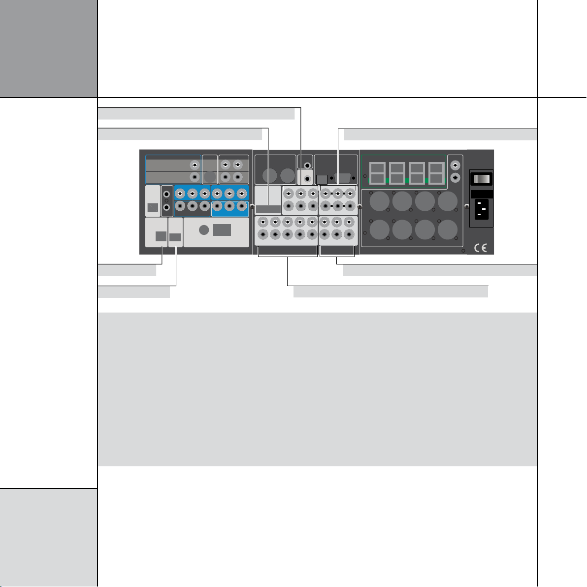
6
COPY
ZONE 2
ZONE 3
DIG OUT COMMS
LLR
R
ANALOGUE OUT
TRIG 2
TRIG 3
+12V 100mA
COMPONENT OUT
Pb/B Pr/R Y/G
Y2CABLE
Pb/B Pr/R Y/G
Y3SAT
Y1DVD
LZ
RZ
MAIN L MAIN R CENTRE SUB
REAR L REAR R SIDE L SIDE R
ANALOGUE OUT
SPEAKERLINK OUT
REAR L+RSIDE L+RC+SUBL+R
MASTER
(ONE ONLY, THIS ROW)
ON OFF
MERIDIAN COMMS
TRIGGER 1
+12V 100mA
OPTICAL IN
O3 O4
D12 D10 D8 DISC
D11
D9 VCR2
D7 CD
SURR C/LFE L/R
MULTIANALOGUE IN
MULTI DIGITAL IN
A8 A7VCR1 A6 CABLE A5TV A4 TAPE SURRR
MIC
LFE RIGHT
SURR L CENTRE LEFT
MA1
AUX
MD1
MD2
DVD
ANALOGUE IN
DIGITAL IN
L
R
IR IN
MAINTENANCE
USB RS232
L
OPT IN
O5
USB AUDIO IN OPT IN
ANTENNA
FM
AM
GND
O1SAT O2GAME
Optical inputs 3 and 4
Multichannel digital coax inputs
Digital coax inputs
USB input
Multichannel analogue input
Optical input 2
Analogue inputs
I ns t a l li n g t h e
d ig i t a l su rr o u n d
c on t r o ll e r
Audio inputs
Use this connector To connect to this
MULTI DIG IN 1 (DVD) or D1-D3,
MULTI DIG IN 2 or D4-D6
DIG IN D7 (CD), D8 (DISC), D9 (VCR2),
The multichannel digital output of a source such as the G96 DVD Transport, a Meridian
HD621, or three digital sources.
The digital output of a source such as a G08 24-bit Upsampling CD Player or DAB tuner.
D10-D12
MULTI AN IN (AUX) or A1-A3 A multichannel analogue source such as an SACD player.
The unbalanced analogue output of a source such as a tape recorder, TV tuner, cable box,
or VCR.
Configuring sources
, page 24.
ANALOGUE IN A4 (TAPE), A5 (TV),
A6 (CABLE), A7 (VCR1)
USB INPUT U1 A computer USB port.
OPTICAL IN O2 (GAME), O3-O5 The optical output of a source such as a satellite receiver or computer game console.
ANALOGUE IN MIC (A8-L) An SPL meter for use in room correction configuration.
The default assignment of the sources to each input is shown in brackets after the input name in the above table. RADIO is normally
assigned to the internal tuner. To assign a different input to a source see
Page 11
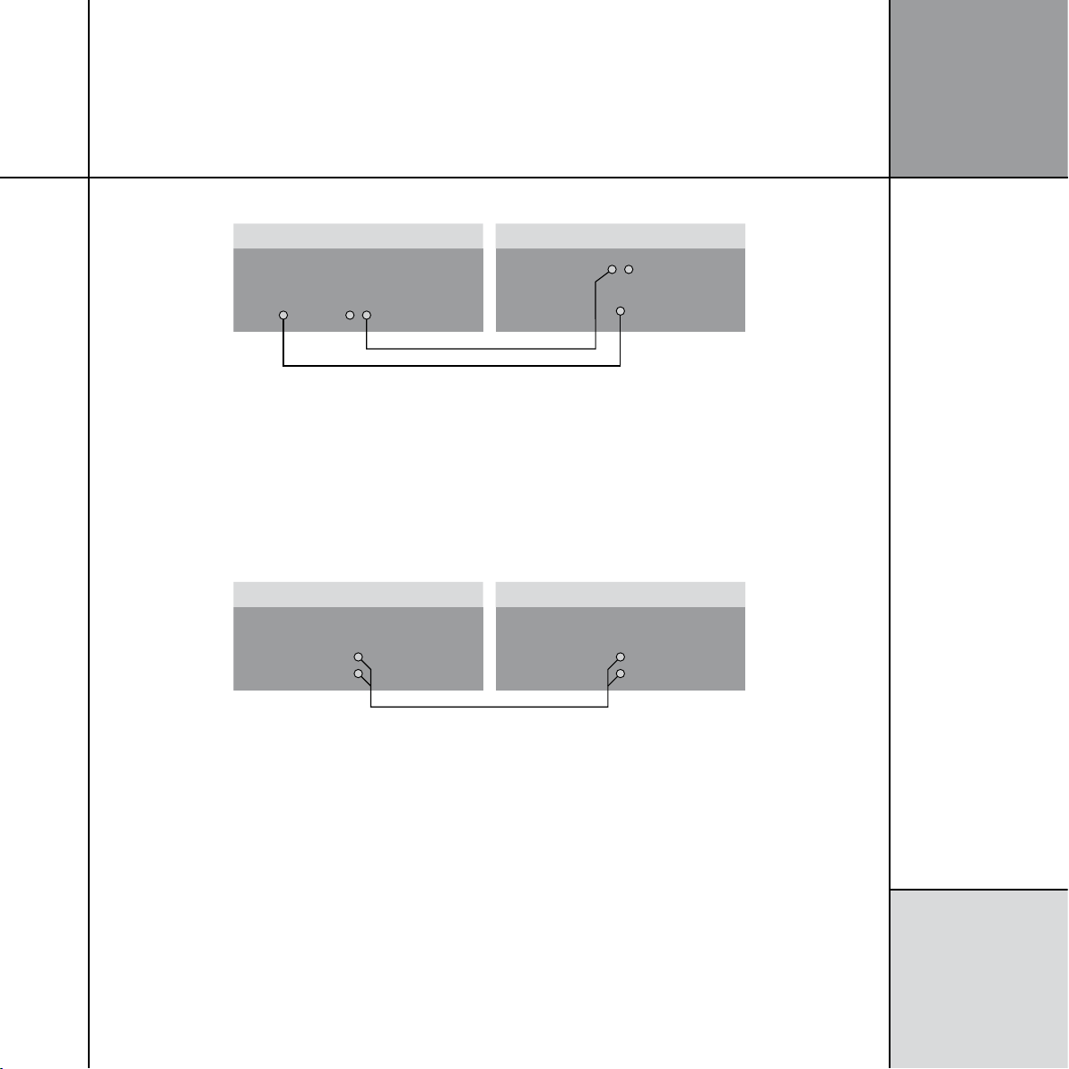
To connect to a digital source (eg G06 24-bit CD Player)
G68 Digital Surround Controller
DIG IN
D7 CD
DIGITAL LEAD
COMMS LEAD
COMMS
DIGITAL OUT COMMS
G06 24-bit CD Player
TV tuner
OUTPUT
PHONO LEADS
G68 Digital Surround Controller
ANALOGUE IN
A5 TV
7
I ns t a l li n g t h e
d ig i t a l su rr o u n d
c on t r o ll e r
You can connect up to 12 digital coax sources to the G68 Digital
Surround Controller.
• Connect the digital source to one of the digital input sockets of
the digital surround controller, using a 75Ω screened coax phono
lead.
To connect to an analogue source (eg TV tuner)
You can connect up to eight analogue sources to the G68 Digital
Surround Controller.
• Connect the analogue source to one of the analogue input
sockets of the digital surround controller, using screened coax
phono leads.
If the source is a Meridian product connect together the COMMS
sockets using the Comms lead provided.
Page 12
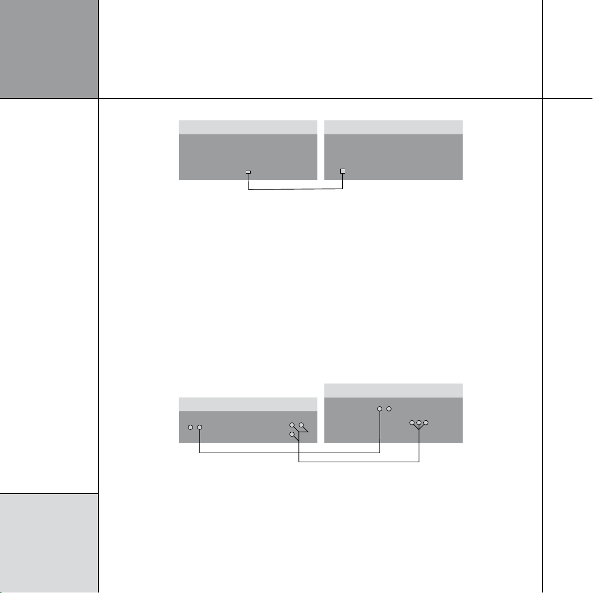
8
Computer
USB
USB A-B CABLE
G68 Digital Surround Controller
USB INPUT
HD621 HDMI Audio Processor
3 x DIGITAL LEADS
COMMS LEAD
G68 Digital Surround Controller
MULTI DIG IN 1
(DVD)
COMMS
COMMS
SMARTLINK
I ns t a l li n g t h e
d ig i t a l su rr o u n d
c on t r o ll e r
To connect to a computer via USB
You can connect a Windows PC or Macintosh to the G68 via the
USB input to allow you to use the G68 as a digital audio output
device.
The first time that the G68 is plugged in to the PC or Macintosh
it will automatically be recognised, and appropriate drivers will be
installed. The G68 will then appear as a sound output device called
Meridian 48k/16 in the Sound control panel (PC) or Sound
On a PC, Windows XP/SP2 or later is required. On a Macintosh,
system preferences panel (Macintosh).
OSX 10.4 or later is recommended. Linux computers that support
USB audio class drivers can also be used.
Note: The computer volume control will have no effect on the
playback volume; use the Meridian system control instead.
• Connect the computer’s USB port to USB INPUT U1 on the G68
using a standard USB A-B cable. The flat rectangular end plugs
into the PC and the square end into the G68.
To connect to a Meridian Smart Source with digital multichannel outputs (eg HD621 HDMI Audio Processor)
The G68 Digital Surround Controller provides 12 digital coax inputs,
six of which can be used as two multichannel inputs from a source
with a suitable digital multichannel output, such as the HD621
HDMI Audio Processor.
• Connect the SmartLink outputs 1/2, 3/4, and 5/6 on the HD612
to the MULTI DIG IN 1 on the G68, using three 75Ω screened
coax phono leads.
• Connect together the COMMS sockets using the Comms lead
provided.
Page 13
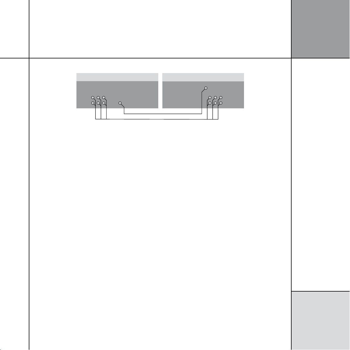
To connect to a source with analogue multichannel outputs (eg SACD player)
SACD player
6 x PHONO LEADS
DIGITAL LEADS
G68 Digital Surround Controller
MULTI AN IN
MULTICHANNEL
OUTPUT
DIG IN D8 DISC
DIGITAL
OUTPUT
The G68 Digital Surround Controller provides eight analogue
inputs, three of which can be used as a multichannel input from a
source with a suitable analogue multichannel output, such as an
SACD player.
• Connect the ANALOGUE OUT sockets from the source to the
analogue multichannel inputs on the digital surround controller
using six phono leads.
• Optionally connect a digital output from the source to digital
input D8 (DISC) on the digital surround controller, using a digital
phono lead.
9
I ns t a l li n g t h e
d ig i t a l su rr o u n d
c on t r o ll e r
You can then select the source corresponding to the multichannel
input (AUX) for playing surround material, and the source
corresponding to the digital input (DISC) to decode other formats.
Note: Multichannel analogue sources may have subwoofer level
outputs that vary by up to 10dB, so it may be necessary to reduce
the LFE level to give correct bass integration; see
DSP presets
, page
37.
Page 14
1 0
COPY
ZONE 2
ZONE 3
DIG OUT COMMS
LLR
R
ANALOGUE OUT
TRIG 2
TRIG 3
+12V 100mA
COMPONENT OUT
Pb/B Pr/R Y/G
Y2CABLE
Pb/B Pr/R Y/G
Y3SAT
Y1DVD
LZ
RZ
MAIN L MAIN R CENTRE SUB
REAR L REAR R SIDE L SIDE R
ANALOGUE OUT
SPEAKERLINK OUT
REAR L+RSIDE L+RC+SUBL+R
MASTER
(ONE ONLY, THIS ROW)
ON OFF
MERIDIAN COMMS
TRIGGER 1
+12V 100mA
OPTICAL IN
O3 O4
D12 D10 D8 DISC
D11
D9 VCR2
D7 CD
SURR C/LFE L/R
MULTIANALOGUE IN
MULTI DIGITAL IN
A8 A7
VCR1A6 CABLEA5TVA4 TAPE SURRR
MIC
LFE RIGHT
SURR L CENTRE LEFT
MA1
AUX
MD1
MD2
DVD
ANALOGUE IN
DIGITAL IN
L
R
IR IN
MAINTENANCE
USB RS232
L
OPT IN
O5
USB AUDIO IN OPT IN
ANTENNA
FM
AM
GND
O1SAT O2GAME
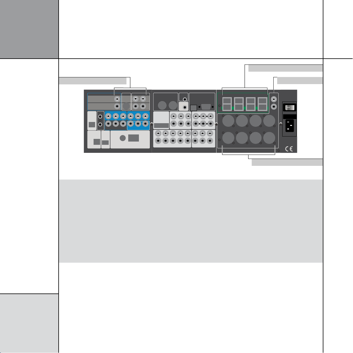
SpeakerLink outputs
Zone 2 and 3 audio outputs
Balanced analogue outputs
Analogue outputs
I ns t a l li n g t h e
d ig i t a l su rr o u n d
c on t r o ll e r
Audio outputs
Use this output To connect to this
L+R, C+SUB, SIDE L+R, REAR L+R Digital loudspeakers, using Meridian SpeakerLink leads or standard CAT5 network
cables. Connect the master speaker to the appropriate socket on the lower row.
Connect the slave speakers to the other sockets as shown in the following diagrams.
ANALOGUE OUT MAIN L, MAIN R, CENTRE,
SUB, REAR L, REAR R, SIDE L, SIDE R
ANALOGUE OUT LZ/RZ A pair of analogue active speakers, the unbalanced analogue inputs of a power
COPY ZONE 2, ZONE 3 ANALOGUE OUT The unbalanced analogue input of a tape recorder, or second and third-room systems.
COPY ZONE 2, ZONE 3 DIG OUT The digital input of a digital recorder, or second and third-room systems.
The balanced analogue input of a power amplifier or active loudspeakers, using XLR
connections.
amplifier, or up to two active subwoofers, using screened coax phono leads.
Page 15
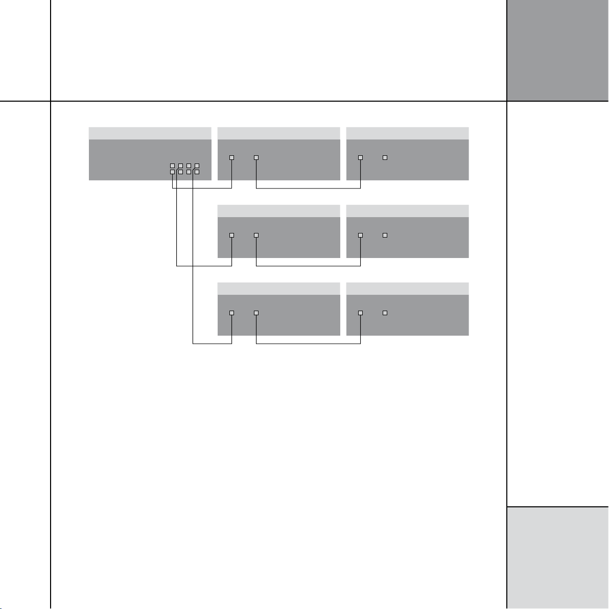
To connect the G68 to Meridian DSP loudspeakers (daisy chain)
G68 Digital Surround Controller
SPEAKERLINK
OUTPUTS
SPEAKERLINK LEAD
SPEAKERLINK LEAD
SPEAKERLINK LEAD
DSP Loudspeaker – Centre (Slave)
SPEAKERLINK
INPUT OUTPUT
DSP Subwoofer – Sub (Slave)
DSP Loudspeaker – Main Left (Master)
SPEAKERLINK
INPUT OUTPUT
DSP Loudspeaker – Main Right (Slave)
SPEAKERLINK
INPUT OUTPUT
DSP Loudspeaker – Rear Left (Slave)
SPEAKERLINK
INPUT OUTPUT
DSP Loudspeaker – Rear Right (Slave)
SPEAKERLINK
INPUT OUTPUT
SPEAKERLINK
INPUT OUTPUT
1 1
I ns t a l li n g t h e
d ig i t a l su rr o u n d
c on t r o ll e r
This is an alternative to the “home run” wiring configuration
shown in the next section.
The G68 automatically assumes that the main left speaker is the
master, unless it is analogue, in which case the DSP centre, left
side, or left rear is used in order of priority (unless explicitly set
differently in the Meridian Configuration program).
• Connect the appropriate
of the G68 to the master digital speaker (typically the main left
speaker), using a Meridian SpeakerLink lead.
SpeakerLink output on the lower row
• Connect the appropriate SpeakerLink outputs on the G68 to one
of each of the remaining pairs of speakers, using a Meridian
SpeakerLink lead.
• Link each pair of speakers together with a Meridian SpeakerLink
lead, out of the first speaker and into the second speaker, as
shown in the diagram.
The speakers should then be configured appropriately as master
and slaves, and Left, Right, Centre, Surround; see
Loudspeaker User Guide
for more details.
Meridian DSP
Page 16
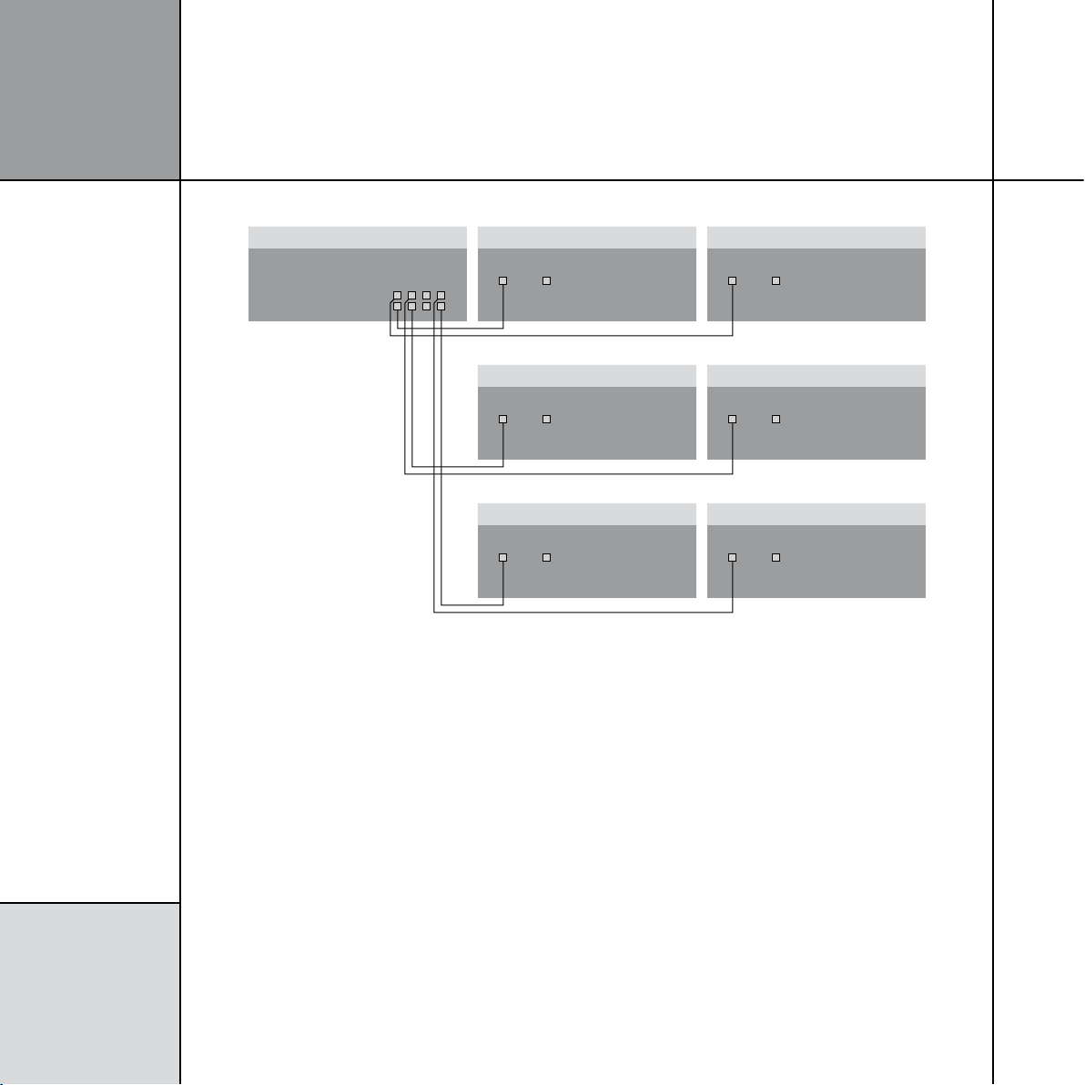
1 2
G68 Digital Surround Controller
SPEAKERLINK
OUTPUTS
SPEAKERLINK LEAD
SPEAKERLINK LEAD
SPEAKERLINK LEAD
DSP Loudspeaker – Centre (Slave)
SPEAKERLINK
INPUT OUTPUT
DSP Subwoofer – Sub (Slave)
DSP Loudspeaker – Main Left (Master)
SPEAKERLINK
INPUT OUTPUT
DSP Loudspeaker – Main Right (Slave)
SPEAKERLINK
INPUT OUTPUT
DSP Loudspeaker – Rear Left (Slave)
SPEAKERLINK
INPUT OUTPUT
DSP Loudspeaker – Rear Right (Slave)
SPEAKERLINK
INPUT OUTPUT
SPEAKERLINK
INPUT OUTPUT
I ns t a l li n g t h e
d ig i t a l su rr o u n d
c on t r o ll e r
To connect the G68 to Meridian DSP loudspeakers (home run)
This is an alternative to the “daisy chain” wiring configuration
shown in the previous section.
The G68 automatically assumes that the main left speaker is the
master, unless it is analogue, in which case the DSP centre, left
side, or left rear is used in order of priority (unless explicitly set
differently in the Meridian Configuration program).
• Connect the appropriate
of the G68 to the master digital speaker (typically the main left
SpeakerLink output on the lower row
speaker), using a Meridian SpeakerLink lead.
• Connect the appropriate SpeakerLink outputs on the G68 to each
of the remaining speakers, using a Meridian SpeakerLink lead.
The speakers should then be configured appropriately as master
and slaves, and Left, Right, Centre, Surround; see
Loudspeaker User Guide
for more details.
Meridian DSP
Alternatively you can use standard CAT5 network cables instead of
SpeakerLink leads.
Page 17
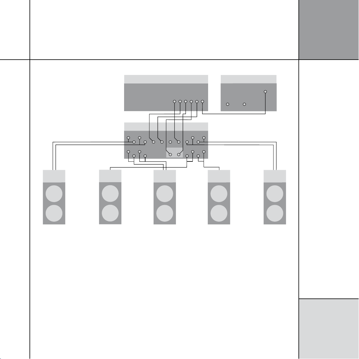
To connect the G68 to power amplifiers or to analogue active and passive speakers powered by a Meridian G41
CHANNEL 1 INPUTS
1 3 4
A B
2
CHANNEL 3
G41 Powered
Crossover/Amplifier
CHANNEL 2
CH. A CH. B
ANALOGUE OUT
G68 Digital Surround Controller
A330
Main right
A330
Centre
P330
Rear right
P330
Rear left
A330
Main left
Analogue subwoofer
COMMS
INPUT OUTPUT
PHONO
1 3
I ns t a l li n g t h e
d ig i t a l su rr o u n d
c on t r o ll e r
The G68 provides eight balanced and two unbalanced analogue
outputs to allow you to connect to power amplifiers and passive
loudspeakers, or 300 Series Active and Passive Installation
Loudspeakers powered by the G41 Active Crossover Amplifier.
• Connect the LEFT and RIGHT analogue outputs to the power
amplifier inputs for the main front loudspeakers.
• Connect the CENTRE analogue output to the power amplifier
input for the centre loudspeaker.
• Connect the REAR L and REAR R analogue outputs to the power
amplifier inputs for the rear loudspeakers.
When the G41 is used with five speakers, as shown above, inputs
A and B for the rear speakers are unbalanced inputs, so use the
unbalanced LZ and RZ outputs.
• If the system includes a subwoofer connect the SUB analogue
output to an active analogue subwoofer, such as the Meridian
SW1600.
Page 18
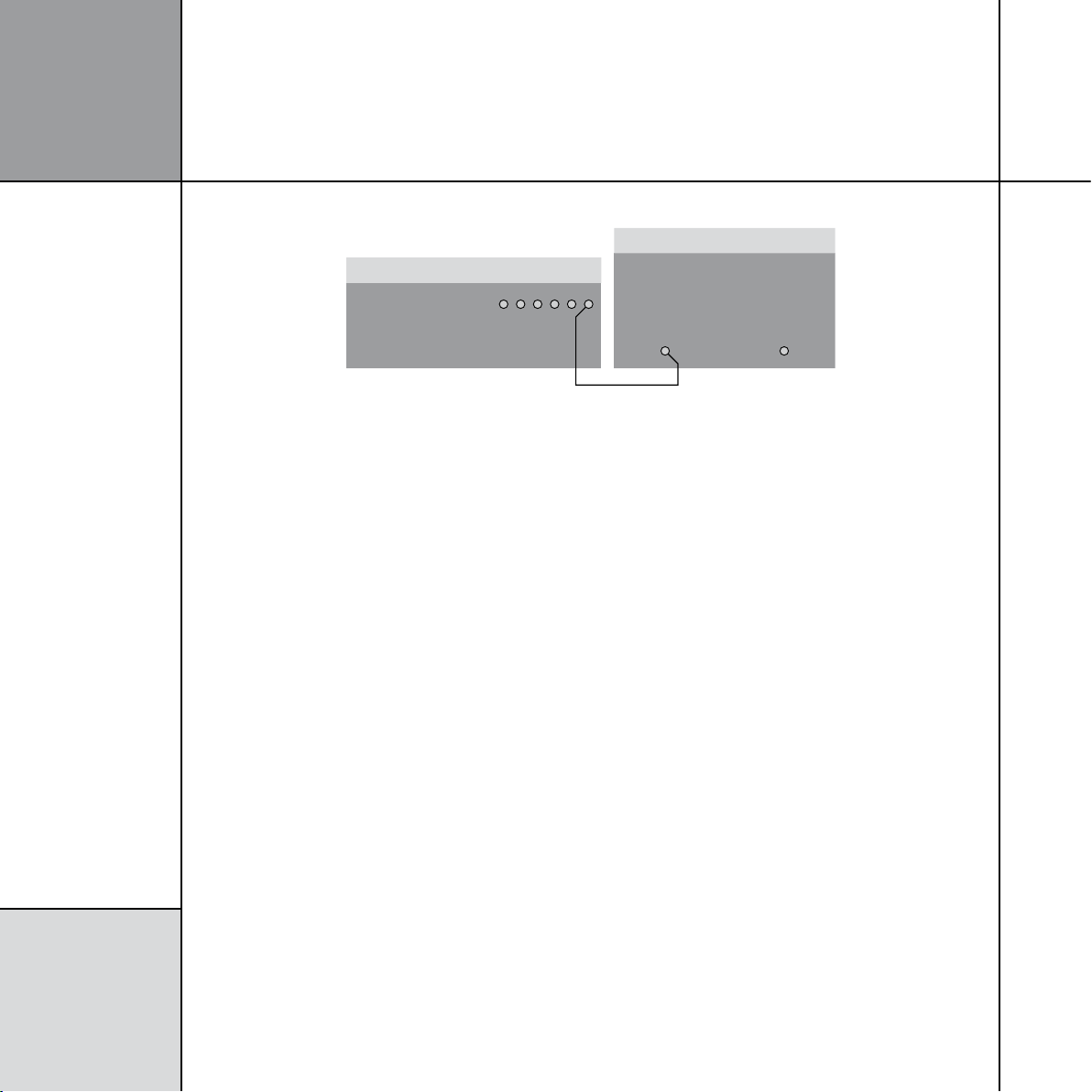
1 4
Subwoofer
PHONO LEAD
G68 Digital Surround Controller
SUB
CROSSOVER
INPUT
DIRECT
INPUT
I ns t a l li n g t h e
d ig i t a l su rr o u n d
c on t r o ll e r
To connect to an active subwoofer (eg Meridian SW1600 or SW5500)
The Meridian SW1600 and SW5500 subwoofers provide both
digital and analogue inputs, allowing you to connect them to
either the digital or analogue subwoofer outputs of the G68. The
analogue connection must be used if you do not have a digital
main speaker.
• Connect the SUB analogue output socket from the G68 Digital
Surround Controller to the subwoofer’s line-level input using a
phono lead.
Use the RZ output (or RZ and LZ if you have two subwoofers).
The digital surround controller provides a very high-quality
crossover for the subwoofer, and for best results you should use
this instead of the subwoofer’s crossover. To do this remove any
crossover in the subwoofer or set it to its highest setting (eg
200Hz). The subwoofer crossover can be set from the front panel of
the G68; see
Subwoofer crossover frequency
, page 34.
Page 19
COPY
ZONE 2
ZONE 3
DIG OUT COMMS
LLR
R
ANALOGUE OUT
TRIG 2
TRIG 3
+12V 100mA
COMPONENT OUT
Pb/B Pr/R Y/G
Y2CABLE
Pb/B Pr/R Y/G
Y3SAT
Y1DVD
LZ
RZ
MAIN L MAIN R CENTRE SUB
REAR L REAR R SIDE L SIDE R
ANALOGUE OUT
SPEAKERLINK OUT
REAR L+RSIDE L+RC+SUBL+R
MASTER
(ONE ONLY, THIS ROW)
ON OFF
MERIDIAN COMMS
TRIGGER 1
+12V 100mA
OPTICAL IN
O3 O4
D12 D10 D8 DISC
D11
D9 VCR2
D7 CD
SURR C/LFE L/R
MULTIANALOGUE IN
MULTI DIGITAL IN
A8 A7
VCR1A6 CABLEA5TVA4 TAPE SURRR
MIC
LFE RIGHT
SURR L CENTRE LEFT
MA1
AUX
MD1
MD2
DVD
ANALOGUE IN
DIGITAL IN
L
R
IR IN
MAINTENANCE
USB RS232
L
OPT IN
O5
USB AUDIO IN OPT IN
ANTENNA
FM
AM
GND
O1SAT O2GAME
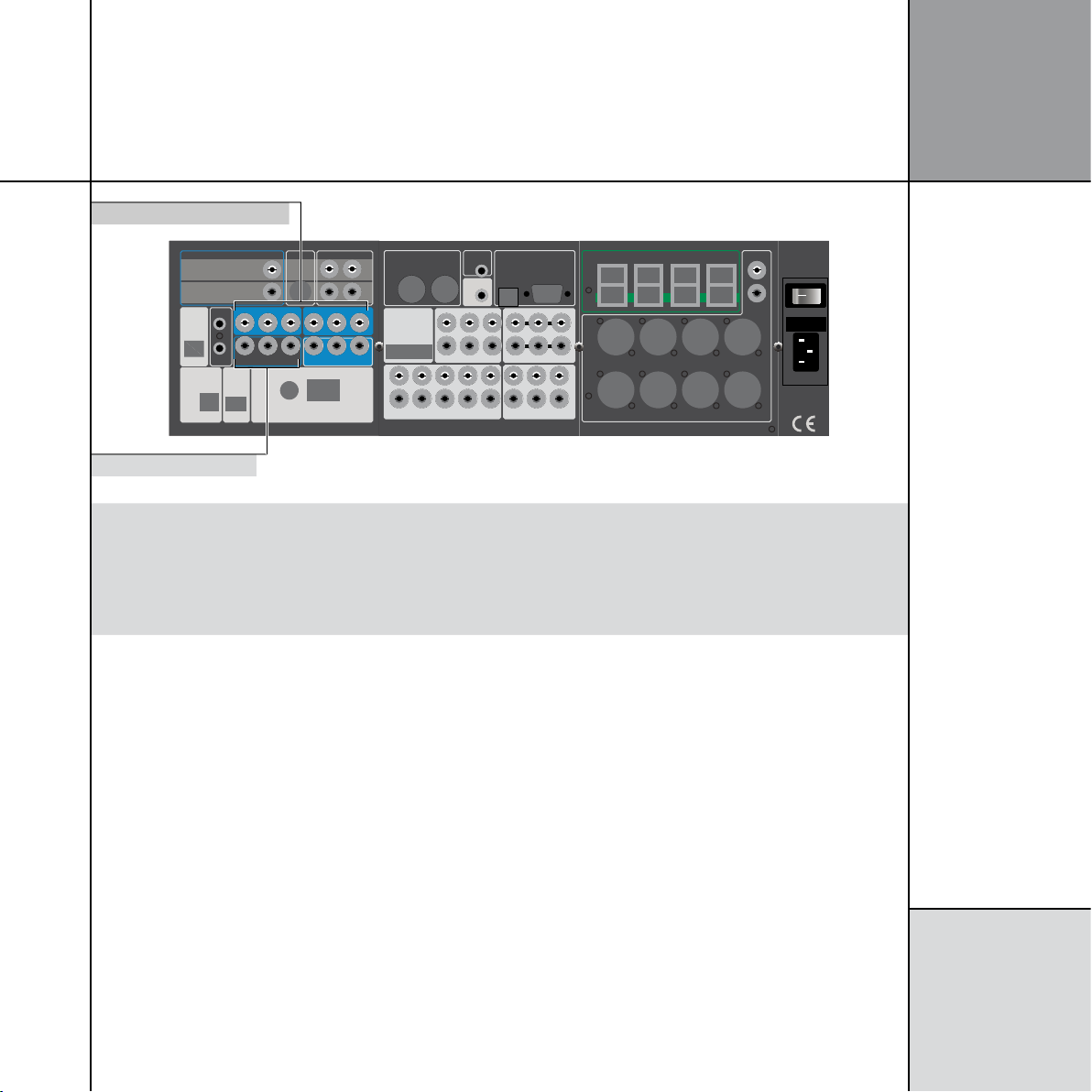
Component inputs
Component outputs
Video connections
Use this connection To connect to this
Y1 (DVD), Y2 (CABLE), Y3 (SAT)
COMPONENT OUT
The component video output of a video source (interlaced or HD), using a 75Ω coax
cable with phono connectors.
The component video input of a TV or monitor, using a 75Ω coax cable with phono
connectors.
1 5
I ns t a l li n g t h e
d ig i t a l su rr o u n d
c on t r o ll e r
Page 20

1 6
COPY
ZONE 2
ZONE 3
DIG OUT COMMS
LLR
R
ANALOGUE OUT
TRIG 2
TRIG 3
+12V 100mA
COMPONENT OUT
Pb/B Pr/R Y/G
Y2CABLE
Pb/B Pr/R Y/G
Y3SAT
Y1DVD
LZ
RZ
MAIN L MAIN R CENTRE SUB
REAR L REAR R SIDE L SIDE R
ANALOGUE OUT
S
PEAKERLINK OUT
REAR L+RSIDE L+RC+SUBL+R
MASTER
(ONE ONLY, THIS ROW)
ON OFF
MERIDIAN COMMS
TRIGGER 1
+12V 100mA
OPTICAL IN
O3 O4
D12 D10 D8 DISC
D11
D9 VCR2
D7 CD
SURR C/LFE L/R
MULTIANALOGUE IN
MULTI DIGITAL IN
A8 A7
VCR1A6 CABLEA5TVA4 TAPE SURRR
MIC
LFE RIGHT
SURR L CENTRE LEFT
MA1
AUX
MD1
MD2
DVD
ANALOGUE IN
DIGITAL IN
L
R
IR IN
MAINTENANCE
USB RS232
L
OPT IN
O5
USB AUDIO IN OPT IN
ANTENNA
FM
AM
GND
O1SAT O2GAME
AM tuner aerial
Trigger output 1
FM or DAB/FM tuner aerial
RS232 connection
Infra-red repeater input
Power & fuse
Meridian DIN Comms connection
Meridian BNC Comms connection
Trigger outputs 2&3
USB connection
I ns t a l li n g t h e
d ig i t a l su rr o u n d
c on t r o ll e r
Tuner and communications connections
Use this connection To connect to this
DIN COMMS Other Meridian G Series, 500 Series, or 800 Series equipment, or Meridian DSP loudspeakers.
BNC COMMS Meridian components with BNC Comms.
RS232 connection A computer, for configuring the digital surround controller.
USB connection A computer, for configuring the digital surround controller.
IR IN A G12 IR Receiver, or approved alternative infra-red receiver. Contact your dealer for details.
ANTENNA FM, AM FM and AM antennae.
TRIG 1, TRIG 2, TRIG 3* Other equipment, via mono 3.5mm jack plug outputs (centre pin hot) providing 12VDC. They are always
low in standby. By default they are high for all sources, so can be used to bring a G Series power
amplifier out of standby. Alternatively you can program them to be high for specific sources; eg to control
a projection screen.
Page 21

To connect to other Meridian G Series, 500 Series, or 800 Series equipment
COMMS
COMMS LEAD COMMS LEAD
G Series or 800 Series unit
COMMS
G68 Digital Surround Controller
Auto
Con.
Not Con.
1 7
I ns t a l li n g t h e
d ig i t a l su rr o u n d
c on t r o ll e r
In a system of Meridian products the products should be linked
together in a chain, via the COMMS sockets, using the Comms
leads supplied with each product. The sequence in which you
connect the units is not important.
One of the products acts as the controller for the system, receiving
infra-red commands from the MSR+, and then, if appropriate,
relaying them to the other products via the Comms link. The
following procedure should be used to set up the Comms correctly
between several products:
• Switch all the units to standby.
Clear (MSR+).
• Press
Each unit will display:
One unit will then be designated as the controller, and display:
All the other units will be configured as non-controllers, and
display:
The system is now ready for use.
If the automatic setup does not work, first make sure you are
operating the MSR+ from a position where all the units can receive
the infra-red, and try again. Then:
• Check that none of the units have been configured to be IR
Controller; see
set to Auto, or one should be configured as Controller and the
others as Not Controller.
Note: Do not, under any circumstances, connect any equipment
other than Meridian G Series or 800 Series to any socket marked
COMMS on the back of the product.
Settings
, page 27. Either all products should be
Page 22

1 8
G68 Digital Surround Controller
AMFM
I ns t a l li n g t h e
d ig i t a l su rr o u n d
c on t r o ll e r
To connect FM and AM antennae
• Connect an FM antenna or split-flex dipole to the FM Coax
connector, if necessary using the adaptor provided.
In the UK use a female Belling-Lee (VCR) connector.
Although the FM tuner is very sensitive, the FM antenna is supplied
for basic installation only, and for best performance and lowest
noise use a high-quality antenna placed as high as possible and
oriented towards the transmitter.
Note: For all outdoor antennae we strongly recommend you use a
qualified installer who will comply with local safety regulations.
• Connect an AM antenna to the AM connector by pressing
the tabs and inserting a bare wire into each hole. The ground
connection (black on the supplied AM antenna) should be
connected to the socket marked GND.
The product is supplied with an indoor loop antenna. This is
directional, and for best results you will need to orient it, and this
may be station dependent.
• Place the antenna as far away from other electrical equipment
and as high as possible.
For best AM results use an external AM antenna.
Note: For AM you must fit a good ground as well as an antenna.
The tuner can be used with most proprietary indoor AM, FM, or
combi (AM/FM) antennae. It is possible in some cases to use a
trigger output (+12V) from the G68 to power such devices.
Page 23

Configuring the digital surround controller
5NLOCK6ERSION
,OCK#ALIB6ERSION )2 7IZARD
This chapter explains how to configure the digital surround controller using the Configuration Wizard.
Alternatively, for complete control over all aspects of the product’s configuration you can set up the unit
from a computer using the Meridian Configuration Program. For full information refer to the
Configuration Program Guide
available separately.
Meridian
1 9
C on f i g ur i n g t he
d ig i t a l su rr o u n d
c on t r o ll e r
Configuration Wizard
The Configuration Wizard leads you through the correct
sequence to configure your digital surround controller. Alternatively,
you can skip between the configuration stages, which allow you to
reset the configuration, or configure the sources or other settings
of the digital surround controller.
To run the Configuration Wizard
• If necessary press
into standby.
More.
• Press
If the product is locked the display shows:
• Press Unlock to unlock it, then press More.
On/Off to put the digital surround controller
The display then shows:
• Press Wizard.
Follow the sequence of configuration stages described in the
following pages, pressing Next to proceed after each stage.
At any stage in the Configuration Wizard the following options are
available:
To do this Press
Go back to an earlier configuration option Back
Return to the title screen for the stage Home
Exit from the configuration menus On/Off
Display help about the current option More
Page 24

2 0
%NTER 3KIP"ACK
0RESS-OREFORHELP
2ESETSETTINGS
"ACK 9ES
2ESETALLSETTINGS
"ACK .EXT z{|wxy
!LL!N-ONO4(83UB
4YPE
C on f i g ur i n g t he
d ig i t a l su rr o u n d
c on t r o ll e r
Stage 1: Resetting the product
The digital surround controller provides several alternative standard
settings, called Types, which configure all aspects of the product
into the most commonly needed configurations.
Choosing one of the Types overrides any other configuration you
may have performed, and so can be used to reset the configuration
of the unit.
To reset the configuration
• Press
Wizard.
The display shows the title screen for stage 1:
• Press Enter to proceed or Skip to go stage 2.
If you pressed Enter the display shows:
• Press A or V to step through the available Types.
A description of the speakers for each type is shown on the top
line of the display. As you select each Type the digital surround
controller is reset to that Type.
When you have selected the Type you want:
Either:
• Press Next to proceed to configuring speakers, as described in
the next section.
Or:
• Press On/Off to return to standby.
• Press Yes to proceed or Back to exit.
The display shows the current Type:
Page 25

Types
The following table lists the available Types:
Type Speakers Music Sub Logic Sub 5.1 Movie Sub
0 All analogue. LFE Centre LFE
1 All analogue. Mono Mono Mono
2 All digital. LFE Centre LFE
3 All digital, large centre. None None None
4 Digital left, right, and centre. LFE Centre LFE
5 Digital left and right. LFE Centre LFE
Music Sub refers to a subwoofer used for all Music DSP presets, Logic Sub to a subwoofer used for all Logic DSP presets, and 5.1 Movie
Sub to a subwoofer used for all 5.1 Movie DSP presets; see
LFE subwoofer is only active in multichannel presets. Mono and Centre Subwoofers are active in all presets.
Speaker layouts
, page 37.
2 1
C on f i g ur i n g t he
d ig i t a l su rr o u n d
c on t r o ll e r
Note that any Types stored using the Meridian Configuration Program will also be available in this list; see the
Program Guide
for more information
.
Meridian Configuration
Page 26

2 2
SkipBack Enter
2: Select speakers
Press More for help
öõú óòô Back Next
Number of Subwoofers:
one
Back Next
Speaker choice finished.
C on f i g ur i n g t he
d ig i t a l su rr o u n d
c on t r o ll e r
Stage 2: Configuring speakers
The Speakers configuration stage allows you to set up the digital
surround controller for the particular arrangement of loudspeakers
in your system.
To configure the speakers
Either:
• Press Next after resetting the product; see
page 20.
Resetting the product
Or:
• Press Wizard; see page 19.
Skip to skip past the Reset settings menu.
• Press
The display shows the title screen for stage 2:
• Press Enter to proceed or Skip to go to stage 3.
The display shows the first speaker configuration option:
A description of each option is shown on the top line of the
display, and its current value is shown below this to the right.
The options are summarised in the table on the next page.
To change an option
• Press
,
A or V to step between the alternative values for the
option.
When you have stepped through all the speaker options the display
shows:
Either:
• Press Next on the last option of the last speaker to proceed to
configuring sources, as described in the next section.
Or:
• Press On/Off to return to standby.
• Press Next or Back to step between options.
If you press On/Off before completing the configuration a warning
is displayed, giving you the option of continuing or abandoning the
configuration.
Page 27

Speaker options
The following table summarises the speaker options:
Option Values Description
Number of Subwoofers: none, one, two, three How many subwoofers.
The main L&R speakers
are:
The Centre is used: always, never, for music, for movies When the centre speaker is to be available.
The Centre speaker is a: small analogue/THX, small DSP, large
Number of Surrounds: none, two, four The total number of rear and side surround speakers.
The Side speakers are: small analogue/THX, small DSP, large
The Rear speakers are: small analogue/THX, small DSP, large
The Subs are used: for movies only, always When the subwoofers are used. If you have small main speakers,
The Sub handles: all the bass, only the LFE Whether to use the subwoofer for all bass or just the LFE channel.
The bass balance is: neutral, heavy Whether the bass is distributed to all the large speakers
The 2 Subs are used for: Left and Right, Front and Surround If there are two subwoofers, their position. Only available if there
The sub is: analogue, digital The type of subwoofer(s).
small analogue/THX, small DSP, large
analogue, large DSP
analogue, large DSP
analogue, large DSP
analogue, large DSP
The types of the main left and right speakers. If you have no
subwoofers, you cannot specify small main speakers.
The type of the centre speaker.*
The types of the side speakers.*
The types of the rear speakers.*
the subwoofer must always be used.
Only available if there is only one subwoofer.
and subwoofer (heavy) or just the subwoofer (neutral –
recommended). Only available if there is only one subwoofer, and
it handles all the bass not just the LFE.
are two subwoofers.
2 3
C on f i g ur i n g t he
d ig i t a l su rr o u n d
c on t r o ll e r
*If you have small main speakers, you cannot specify small centre or surrounds.
Page 28

2 4
SkipBack
Press More for help
Enter
3: Configure sources
öõú óòô Back Next
This source is:
Source
Radio in use
C on f i g ur i n g t he
d ig i t a l su rr o u n d
c on t r o ll e r
Stage 3: Configuring sources
The digital surround controller provides up to 12 sources
corresponding to the 12 source keys on the MSR+:
CD, RADIO, DVD, AUX, DISC, TAPE, TV, CABLE, SAT, VCR1, VCR2,
GAME.
For each source the Configure sources stage allows you to
configure a series of options, including:
• Whether it is in use.
• The label used for it on the front-panel display.
• The audio input it selects.
• The TRIGGER output level it selects.
The procedure for doing this is as follows.
To configure a source
Either:
• Press Next after configuring speakers; see page 22.
Or:
• Press Wizard; see page 19.
Skip to skip past the Reset settings and Select
• Press
speakers menus.
The display shows the first source and the first configuration option
for that source, whether it is in use:
• Press Next or Back to step between options.
The top line of the display shows a description of each option, and
its current value is shown to the right of the source name.
When changing the source name, Next and Back step between
character positions.
The options are summarised in the table on the next page.
To change an option
• Press
A or V to step through the alternative values for the
option.
To move to the next source
• Press
Source.
When you have finished configuring sources:
The display shows the title screen for stage 3:
• Press Enter to proceed or Skip to go to stage 4.
Either:
• Press Next on the last option of the last source (Game) to
proceed to configuring settings, as described in the next section.
Or:
• Press On/Off to return to standby.
Page 29

Source options
The following table summarises the source options:
Option Values Description
The source is: in use, not in use Whether the source is enabled.
Audio input: D1-D12, MD1-MD2, U1, O2-O5, Tuner,
A1-A8, MA1, Last Valid*
Component Input: Y1-Y3, Last Valid*, Blank Component video input used for the source.
Source name: Any name of up to five characters.
Copy/Zone use main
inputs:
Copy/Zone 2 audio input: D1-D12, MD1-MD2, U1, O2-O5, Tuner,
Zone 3 audio input: D1-D12, MD1-MD2, U1, O2-O5, Tuner,
Trigger #1: High, Low, Last Valid Trigger outputs for the source.
Trigger #2: High, Low, Last Valid Trigger outputs for the source.
Trigger #3: High, Low, Last Valid Trigger outputs for the source.
Comms Type: CD 1C, Tuner 2C, DVD 3C, Sooloos 4C,
Comms Address: 1A-8A Allows you to have up to eight of each source type.
yes, no If no, provides options for feeding separate inputs to the Copy/
A1-A8, MA1, Last Valid*
A1-A8, MA1, Last Valid*
5C-8C, No Comms NC
The audio input used for the source; digital, multichannel digital,
USB, optical, tuner, analogue, or multichannel analogue.
Zone outputs.
The audio input used for Copy/Zone 2.
The audio input used for Zone 3.
Set to NC unless the source is a Meridian or Sooloos product.
2 5
C on f i g ur i n g t he
d ig i t a l su rr o u n d
c on t r o ll e r
*Last Valid leaves the input set to the last input you selected.
Page 30

2 6
SkipBack Enter
4: Other settings
Press More for help
öõú óòô Back Next
Tuner region:
Europe/elsewhere
C on f i g ur i n g t he
d ig i t a l su rr o u n d
c on t r o ll e r
Stage 4: Configuring other settings
The next stage allows you to configure other aspects of the
product’s operation.
To configure other settings
Either:
• Press Next after configuring the sources; see page 24.
Or:
• Press Wizard; see page 19.
Skip to skip past the stages 1 to 3.
• Press
The display shows the title screen for stage 4:
• Press Enter to proceed or Skip to go to the calibration
procedure.
The first setting is displayed:
To change a setting
• Press
A or V to step through the alternative values for the
setting.
To calibrate the system
When you have finished configuring the settings:
Next to proceed to calibrating the system, as described in
• Press
the next chapter.
Alternatively, to return to standby:
On/Off.
• Press
A description of each setting is shown on the top line of the
display, and its current value is shown to the right of the display.
The settings are summarised in the table on the next page.
Page 31

Settings
The following table summarises the product settings:
Option Values Description
Tuner region: Europe/elsewhere, Japan, USA Band selection (MW/LW or AM), tuning steps, and FM
deemphasis standard. For all countries except the USA or
Japan use the Europe setting.
The fan is: used as necessary, never used Specifies how the temperature controlled fan operates.
Distance measurement: feet/inches, metres Units for displaying and entering distances.
Do your subs play to 20Hz? No, THX Ultra2/yes Subwoofer frequency response.
Boundary Gain Compensation: off, on Reduces the bass to compensate for listening positions close
to a wall.
Rear speaker separation <12"/0.3m, 12-48"/0.3-1.2m,
>48"/1.2m
Use AAC decoder to decode: all Zone 2 streams, AAC to main out Action of AAC decoder; only if a tape card is fitted.
Zone 2 digital output is: decoded, bitstream Zone 2 digital output format when previous option is set to
Copy/Zone 2 analogue out: fixed, variable Whether the Copy/Zone 2 analogue output is controlled by the
Zone 3 analogue out: fixed, variable Whether the Zone 3 analogue output is controlled by the
Timeout to Home buttons: on, off Whether the soft keys revert to the home keys after a delay.
Diagnostic displays: on, off Whether diagnostic displays are shown.
Is the G68 IR Controller? Auto, Controller, Not Controller Whether the product is the infra-red controller for the system.
Main System Address 1-8 Advanced setting (normally 1).
Copy System Address 1-8 Advanced setting (normally 2).
Zone System Address 1-8 Advanced setting (normally 3).
Product Address 1-8 Advanced setting (normally 1).
Separation between rear speakers; only available when there
are four surrounds.
Zone 2.
volume control.
volume control.
2 7
C on f i g ur i n g t he
d ig i t a l su rr o u n d
c on t r o ll e r
Page 32

2 8
,OCK#ALIB6ERSION )2 7IZARD
C on f i g ur i n g t he
d ig i t a l su rr o u n d
c on t r o ll e r
To toggle the IR mode
• If necessary press
On/Off to put the surround controller into
standby.
More.
• Press
The display shows:
• Press IR to toggle between IR Auto (auto setup), IR Con.
(controller), and IR N.Con. (not controller).
After a short delay the surround controller will return to standby.
Page 33

Calibrating the system
To help you to set up the installation to give the best possible sound with any particular
combination of associated equipment, the G68 Digital Surround Controller includes a built-in
calibration procedure.
This calibration procedure uses test signals to present a series of sounds, which you use to
adjust certain aspects of the system to their optimum settings.
You should use the calibration procedure the first time you set up the system, and whenever
you want to check the calibration, such as after changing the layout of the room.
2 9
C a l i b r a t i n g
t h e s y s t e m
Introduction
We recommend that you perform the calibration procedure using
the MSR+ and from the listening position.
As you run the calibration procedure the name of each calibration
test is shown on the front-panel display, followed by the
parameters adjusted in the test.
Each calibration test uses a test signal designed to give the best
results.
Using a Sound Pressure Level meter
Although you can perform the calibration procedure by ear, it is
recommended that you perform the tests using a Sound Pressure
Level meter.
Set the Sound Pressure Level meter to C weighted, and Slow. Take
readings with the meter at the listening position, pointing vertically.
You should hold the meter with an outstretched arm to minimise
reflections from your body.
You can choose to display and enter distances in either feet and
inches or metres.
Page 34

C a l i b r a t i n g
t h e s y s t e m
3 0
UnlockVersion
,OCK#ALIB6ERSION )2 7IZARD
Left Level +0.0dB
ìî ïñ öõú óòô
Press More for help
Back Next Restart
Calibration complete.
RestartBack Exit
Press More for help
Wizard complete
To start the calibration procedure
Either:
• Press Next on the last option of configuring settings; see
calibrate the system
, page 26.
To
Or:
• Press On/Off to put the digital surround controller into standby.
More.
• Press
If the product is locked the display shows:
• Press Unlock.
The display shows:
For more detailed information about this and the other calibration
tests see the following sections.
To exit from the calibration procedure
You can exit from the calibration procedure at any time, and any
parameters you have set will be retained:
On/Off.
• Press
To complete the calibration procedure
When you reach the end of the calibration procedure the following
display confirms that you have completed the calibration of the
system:
• Press Restart to restart the calibration procedure, or Next to
complete the wizard.
The display shows:
• Press Calib.
The displays shows Please wait….
After a few seconds the display shows the first calibration test:
Either:
• Press Exit to return to standby.
Or:
• Press Restart to return to stage 1; see
product
, page 20.
Stage 1: Resetting the
Page 35

Left Level +0.0dB
ìî ïñ öõú óòô
Press More for help
CentreSub
Left Right
Left
Side
Right
Side
Left Rear Right RearSurround Sub
Calibration tests
3 1
C a l i b r a t i n g
t h e s y s t e m
Levels
These tests allow you to adjust the output level to each speaker
individually, and it follows the general guidelines from Dolby
Laboratories and THX.
In each test the display shows the speaker being tested, and the
current relative level. For example:
• Use > and < to move between each of the speakers in the
layout in the sequence: Left, Centre, Right, Side R, Rear R, Rear L,
Side L, and subwoofers.
A and V to adjust the level of the speaker. Ignore any tonal
• Use
difference.
For correct THX reproduction you should adjust each speaker to
75dB SPL using an SPL meter. Even if the speakers are not THX
approved this setting is recommended.
If you have Meridian DSP loudspeakers they cannot be set above
+0dB.
Note: You cannot set the level of a subwoofer by ear, because
low-frequency noises sound quieter. To set the subwoofer correctly
either use an SPL meter, or set it by ear and then reduce the
subwoofer gain by 15dB to correct for human hearing.
• When you have completed the Levels section press
to the next test.
> to proceed
Distance
These tests allow you to adjust the delay of each of the speakers in
the layout to time-align the system so that sounds are coincident
when they arrive at the listening position.
Before setting up the speaker outputs you need to measure the
distance to each speaker from the listening position:
Measure from ear height at the listening position to the tweeter
on each speaker (where applicable), in the distance units you have
chosen; see
Settings
, page 27.
Page 36

C a l i b r a t i n g
t h e s y s t e m
3 2
Left Distance 18'0
Units ìî ïñ öõú óòô
Press More for help
Left Phase +
ìî ïñ öõú óòô
Press More for help
Left Distance 18'0
ìî ïñ öõú óòô
Press More for help
• Use > and < to move between each of the speakers in the
layout.
The display shows the speaker being tested, and the distance:
• Use A and V to change the distance.
• You can press
Repeat this for each of the speakers in your layout.
• Press
Units to change between feet/inches and metres.
> to proceed to the next calibration stage.
Fine tuning
These tests allow you to fine-tune the phase and delay of each
speaker when used in conjunction with other speakers on the
layout.
> and < to move between each of the speakers in the
• Use
layout.
The next display shows the distance for the same speaker. For
example:
• Choose the correct setting as follows:
Setting What it sounds like
Correct The sound between the speakers is very even, and
does not change radically as you move your head.
Incorrect The sound appears diffused, and changes in timbre
and apparent location as you move your head.
Pay particular attention to the centre channel, as this can have a
dramatic effect on the overall sound.
> to proceed to the next calibration stage.
• Press
The first display allows you to adjust the phase. For example:
Page 37

ìî ïñ öõú óòô
Press More for help
Sizes set to zero
ìî ïñ öõú óòô
Press More for help
Left Size 0
Speaker size
These tests allow you to determine the bass handling capability
of subwoofers and large analogue speakers. Once set, the digital
surround controller will limit the bass level to protect the speakers
from potential damage.
On starting the test the speaker sizes are set to zero to avoid the
possibility of damaging the speakers, and the display shows:
The display then shows the first large analogue speaker; for
example:
3 3
C a l i b r a t i n g
t h e s y s t e m
• Press A or V to adjust the size value for the speaker until it just
begins to distort distinctly, and then reduce the value by one.
> or < to move between each of the speakers to be
• Press
adjusted.
This is the last test in the calibration procedure; see
the calibration procedure
To complete
, page 30.
Page 38

C a l i b r a t i n g
t h e s y s t e m
3 4
3INE3UB3ENS
2ADIO4RIFIELD
3INE 8OVER 3ENS
2ADIO4RIFIELD
Sine -Xover+ -Sens.+
C
D Xover 85Hz
Using the Sine/Sub/Sens controls
This section explains how to use the Sine/Sub/Sens controls
to check for room resonances, adjust the subwoofer crossover
frequency, or adjust the sensitivity of the analogue sources.
To display the Sine/Sub/Sens controls
• If necessary, unlock the digital surround controller as described in
Configuration Wizard
• Select a source and press
display shows:
• Press Sine/Sub/Sens.
The bottom line of the display shows the Sine/Sub/Sens controls:
, page 27.
More until the bottom line of the
Subwoofer crossover frequency
The G68 Digital Surround Controller allows the crossover frequency
for any subwoofers which you have to be adjusted between 30 and
150Hz. The crossover can be set independently for Music, Logic,
and 5.1 Movie layouts. The default is the THX standard of 80Hz.
To adjust the subwoofer crossover frequency
• Select a source, then display the
described above.
Sine/Sub/Sens controls as
Xovr- or Xovr+ to decrease or increase the crossover
• Press
frequency.
The display shows the current crossover frequency:
For THX loudspeaker systems you should not adjust these settings;
they should be left at 80Hz. 80Hz is also the recommended setting
for all movie listening. You may prefer, however, to lower the
crossover frequency for music if the main speakers have good bass
handling down to, say, 50Hz.
Sinewave sweep test
The G68 includes a sinewave signal test, to help you set the
subwoofer crossover frequencies, or check for room resonances. To
avoid possible damage to the speakers the volume is reduced to 50
on entering the test.
Warning: This test is very loud. Bass protection is turned
off during this test, and very loud low-frequency signals
may damage the speakers.
To use the sinewave sweep test
• Select a source, then display the
described above.
Sine to turn on the sinewave signal.
• Press
Sine/Sub/Sens controls as
Page 39

3 5
Chan óòô öõú ExitSound
C
D Sine 80.0Hz
Chan óòô öõú ExitSound
C
D >> 88.5Hz
Chan óòô öõú ExitSound
C
D > 81.5Hz
Chan óòô öõú ExitSound
C
D Pause 80.0Hz
Chan óòô öõú ExitSound
C
D < 78.5Hz
Chan óòô öõú ExitSound
C
D << 70.5Hz
C a l i b r a t i n g
t h e s y s t e m
The display shows:
An 80Hz sinewave will be played through all channels.
You can change the test signal using the menu keys, as described
in the following sections.
To select the channel
• Press
Chan.
You can select any individual channel, or All Channels.
To change the sweep rate
• Press
A or V to change the sweep rate and direction, as
follows:
Display Description
Fast sweep up.
To change the volume
• Use the volume keys in the usual way.
To change the input
• Press
Sound.
You can select between the following inputs:
Option Description
Input The current input.
Sine A sinewave.
Noise Pink noise, band pass 500Hz to 2kHz for main
channel.
Silent Silence.
Alternatively you can switch between inputs using the menu keys
on the MSR+.
Slow sweep up.
Paused.
Slow sweep down.
Fast sweep down.
Page 40

3 6
Sine -Xover+ -Sens.+
T
V 1.4V Peak -3
Sine -Xover+ -Sens.+
T
V 2.0V Clip -0
Sine -Xover+ -Sens.+
D
VD Not Analogue
C a l i b r a t i n g
t h e s y s t e m
Setting up sources
This section explains how to use the Sine/Sub/Sens controls to
adjust the sensitivity of the analogue sources.
To adjust the sensitivity of a source
To obtain the best signal-to-noise ratio for each analogue source
you can adjust its sensitivity to give the highest level that does not
produce clipping.
• Select the source you want to adjust, with loud source material
playing.
• Display the
• Press
The display shows the current sensitivity and the peak level; for
example:
You can adjust the sensitivity between 0.7, 1.0, 1.4, 2.0, and 2.8V
(least sensitive).
Sine/Sub/Sens controls as described above.
Sens- or Sens+ to decrease or increase the sensitivity.
The display shows, for example:
In this case reduce the sensitivity by selecting a higher number.
If you have selected a digital source you cannot adjust the
sensitivity and the display shows, for example:
If the sensitivity is set too high the input will clip the loudest
passages, and the peak will be 0dB.
Page 41

DSP presets
This chapter gives details of the DSP presets and their parameters, and describes how to
modify them.
3 7
D S P p r e s e t s
DSP presets
The G68 Digital Surround Controller provides two types of DSP
preset. One set is available if the input is two-channel; eg from a
traditional stereo source. The other set is available if the input is
5.1 or 6 channels of discrete audio; eg from a Dolby Digital DVD.
The DSP presets available in each set are described in the following
pages.
Speaker layouts
The G68 Digital Surround Controller provides great flexibility in
the way in which you use the loudspeakers in your system. For
example, the speaker step of the Configuration Wizard allows
you to use the subwoofers and centre speaker only for movie
material see
Configuration Program you can specify three different speaker
layouts, each with a different use of subwoofers and centre
speaker:
Configuring speakers
, page 22. With the Meridian
Layout Description
Music For music presets: two-channel (eg Trifield) and
multichannel (eg Discrete).
Logic For two-channel movie presets: eg PLIIx Movie.
5.1 Movie For multichannel movie presets: eg Cinema.
Page 42

3 8
D S P p r e s e t s
Standard parameters
All DSP presets (except Mono and Direct) provide the following
standard parameters.
Individual DSP presets provide additional parameters, to allow you
to adjust specific features provided by that preset. For full details
refer to information about each preset later in this chapter.
Parameter Range Default What it changes
Treble* -10dB to +10dB +0dB The slope of the frequency response.
Bass* -5dB to +5dB +0dB The bass response.
Phase* + or - + The phase of all loudspeakers.
Axis† -2 to +3 -1 The vertical balance.
Balance <10 to 10> <0> The L-R balance.
HS Output?* Y or N Y Select Y for high-rate audio, upsampled if necessary. Select N for
standard-rate audio, downsampled if necessary.
Centre -3.0dB to +3.0dB +0.0dB The level of the centre.
Depth -2.5ms to +5.0ms +0.0ms The delay of the centre.
Rear -30dB to +10dB +0dB The level of the rears.
Sides -30dB to +10dB +0dB The level of the sides.
R Delay 0ms to 30ms Varies The delay of the rears.
S Delay 0ms to 30ms Varies The delay of the sides.
LipSync 0ms to 30ms 0ms The sync. delay.
RC As defined Bypassed The Room Correction profile, or Bypassed for no room correction.
*These parameters apply to all DSP presets.
†Axis is only available with Meridian DSP loudspeakers.
Page 43

3 9
D S P p r e s e t s
DSP presets for two-channel material
The G68 provides several signal processing options for two-channel
material. The Music DSP presets are designed for use with music
from sources such as CD or radio:
• Music, Trifield, Ambisonics, Super Stereo, Music Logic, PLIIx Music,
Stereo, and Direct.
The Logic DSP presets are designed for use with film soundtracks
or TV programmes:
• PLIIx Movie, PLIIx THX, TV Logic, and Mono.
The Music and Logic DSP presets use the Music and Logic speaker
layout respectively; see
Music
The Music DSP preset extracts the mono and surround components
of the original recording. These components provide an alternative
representation of the original sound, and this is sometimes used
for recording systems or in broadcasts such as FM radio. The mono
element is equalised using a proprietary Meridian technique to
match the tone colour of the centre speaker, and to compensate
Speaker layouts
, page 37.
for the fact that the frequency response of human hearing changes
with direction.
The Music DSP preset is recommended for recordings made with
spaced omnidirectional microphones, or using a mono-surround
technique.
Trifield
As for the Music DSP preset, the Trifield preset extracts the mono
and surround components of the original recording. It then
calculates the signals for the front, left, centre, and right speakers,
using the phase and amplitude differences between the three front
channels, to redistribute the sounds on a frequency-dependent basis.
This gives a significant improvement over traditional stereo, which
converts the differences between the microphone signals into
amplitude differences in the speaker signals. This version of the
Trifield algorithm is virtually impossible to implement without
digital signal processing.
Trifield is recommended for well-made recordings and stereo
television broadcasts that are not Dolby Surround encoded. An
advantage over the Music DSP preset is that the front stereo image
is more focused, and the width of the image can be adjusted.
Music and Trifield DSP preset parameters
Parameter Options What it changes
Centre Flat, EQ1-3 The timbre of the centre loudspeaker.
Width† 0-1.5 The width of the image.
Surr. Rear Surr. Rear, Surr. Side, Surr. All Switches the surround signal between the side and rear speakers.
R Filter Off, 1kHz, 3kHz, 7kHz The cutoff of high frequencies from the rear surrounds.
S Filter Off, 1kHz, 3kHz, 7kHz The cutoff of high frequencies from the side surrounds.
†Trifield only.
Page 44

4 0
D S P p r e s e t s
Ambisonics
The Ambisonics DSP preset can decode UHJ format, the two-
channel stereo-compatible encoding found on Ambisonically-
recorded discs and broadcasts. This material is specifically encoded
for surround reproduction and can give breathtakingly realistic
sound when replayed using the digital surround controller.
Ambisonics surround sound is quite unlike conventional stereo. A
special microphone technique picks up the sound of the original
performance in all three dimensions, allowing an archive to be
made which describes the soundfield exactly at that position. The
microphone signals are then encoded using a phase-amplitude
matrix to allow the effect to be conveyed on two-channel carriers
(like FM radio, LP, or CD).
The digital surround controller uses accurately matched, frequency-
dependent, phase-amplitude matrices to decode the signal and
construct the signals for each speaker feed.
Ambisonics and Super DSP preset parameters
Parameter Options What it changes
Width* 0 to 1 The width of the image.
Row† A, C, E, G, I, K, M The seating position; the letters are like rows in a hall.
Channels 7, 6, 5, 4 The number of speakers.
R Filter Off, 3kHz, 7kHz, 9kHz The cutoff of high frequencies from the rear surrounds.
S Filter Off, 3kHz, 7kHz, 9kHz The cutoff of high frequencies from the side surrounds.
The fundamental difference between Ambisonics surround sound
and conventional stereo is that the signals from all the speakers
combine to produce a coherent soundfield at the listening position,
giving the illusion that you are sitting inside the recording space
whether you are at the exact central seat or well off to one side.
Of all the signal-processing options, Ambisonics is the one that
requires the greatest attention to speaker choice and positioning.
Super
Super synthesises a signal from a conventional stereo recording
or broadcast so that it can be decoded using the Ambisonic
decoder. The result is especially effective for two particular types of
recordings:
• Those using true coincident microphone techniques.
• Multi-tracked or multi-miked recordings.
*Super only.
†Ambisonics only.
Page 45

MusicLogic
MusicLogic is a music DSP preset based on Pro Logic II with
the addition of user-adjustable steering, designed to provide an
exciting experience with many types of studio-produced music.
MusicLogic DSP preset parameters
Parameter Options What it changes
Roll Off, Low, Med, Max The degree of left-right steering.
Yaw Off, Low, Med, Max The degree of front-rear steering.
Steered All Steered Rear, Steered Side, Steered All Which of the four surround channels are generated by steering.
PLIIx Music
The PLIIx Music preset is designed to use the Pro Logic IIx DSP
processing mode to decode music sources. It provides additional
Width, Dimension, and Panorama preset parameters to allow
you to adjust the soundfield.
4 1
D S P p r e s e t s
PLIIx Music DSP preset parameters
Parameter Options What it changes
Steered All Steered Rear, Steered Side, Steered All Which of the four surround channels are generated by steering.
Width 0 to 7 The centre spread, where 0 is full centre and 7 is full left and right.
Dimension -3 to +3 The spatial soundfield, where -3 puts the balance to the rear of the room
and +3 puts it to the front.
Panorama No, Yes Extends the front stereo image to include the surround speakers, providing
a wrap-around effect new to Pro Logic.
Page 46

4 2
D S P p r e s e t s
Stereo and Direct
The Stereo preset passes the left and right input signals directly to
the left and right main speakers. Any mono or front left and right
subwoofers continue to be used.
With the Direct preset only the left and right main speakers are
used, bypassing any spatial processing and bass management.
There are no additional DSP preset parameters for Stereo and
Direct.
PLIIx Movie and PLIIx THX
PLIIx Movie and PLIIx THX use the Dolby Pro Logic IIx DSP
processing mode, and are the recommended choice for Dolby
Surround encoded material. They also give excellent results with
two-channel sources not specifically encoded for Dolby Surround,
including two-channel Dolby Digital sources.
Pro Logic IIx re-creates 7.1-channel movie surround from the two-
channel source, using improved decoding techniques that preserve
the directness of the soundfield, resulting in enhanced image
PLIIx Movie and PLIIx THX DSP preset parameters
stability compared with the original Pro Logic decoding. Meridian’s
implementation of Pro Logic IIx uses proprietary code based on 48-
bit precision to give outstanding clarity.
The PLIIx THX DSP preset uses the same PLIIx processing as PLIIx
Movie, but adds THX Cinema processing. THX is a set of standards
and technologies developed by Lucasfilm Ltd. with the aim of
making your experience of the film soundtrack as faithful as
possible to what the director intended.
Re-equalisation is used to restore the correct tonal balance for
watching a film soundtrack in a small home environment.
Timbre matching filters the information going to the surround
speakers so that they more closely match the tonal characteristics
of the sound coming from the front speakers. This ensures seamless
panning between the front and surround speakers.
THX can also be used with the 5.1 Movie DSP presets; see
page 53.
THX
,
Parameter Options What it changes
Surrounds Rear, Side, All Which of the four surround channels are generated by steering.
Pro Logic Off, On On selects an emulation of the original Pro Logic decoding.
Page 47

TV Logic
TV Logic is a Logic preset based on Pro Logic IIx with the addition
of user-adjustable steering, designed to give higher intelligibility
and a more appropriate spatial presentation for studio-based TV
material.
TV Logic DSP preset parameters
Parameter Options What it changes
Roll Off, Low, Med, Max The degree of left-right steering.
Yaw Off, Low, Med, Max The degree of front-rear steering.
Surrounds Rear, Side, All Which of the surround channels are generated by steering.
4 3
D S P p r e s e t s
Mono
In the Mono DSP preset you can choose to listen to:
• Only one of two input channels, such as when different
languages or material are carried on each channel.
• A combined version of the two input channels, such as if the
material was originally mono and has been conveyed on a two-
channel carrier.
Mono DSP preset parameters
Parameter Options What it changes
Input Auto L+R, Input L, Input R, Input L+R The channel selected.
Academy Off or On Select On to include an equalisation (recommended by Lucasfilm Ltd) to
Party? No or Yes Select Yes to play the mono signal through all speakers, including
If Party? is set to No, the combined or selected signal is played
only through the centre speaker, or the left and right speakers if
there is no centre, to centrally localise high-frequency hiss and
clicks.
Note: If Party? is set to Yes, full range bass is played through any
speakers that are not supplemented by a subwoofer, and this may
damage small speakers at high volume levels.
correct for a high-frequency balance in some old mono films.
subwoofers.
Page 48

4 4
D S P p r e s e t s
DSP presets for multichannel material
Multichannel audio signals can come from either encoded data
streams (such as Dolby Digital) or as discrete channels from a DVD
player. If you are using Meridian SmartLink then all formats will
reach the G68 as discrete channels. With suitable loudspeakers the
G68 can upsample these to provide a more enjoyable surround
experience.
The G68 Digital Surround Controller will automatically select the
right decoder algorithm and present the same set of preset choices
for all streams. Note: Some presets are only available if there are
four surround speakers in the system.
There are four multichannel Music presets:
• Discrete, PLIIx Mus6, THX Music, and Ambisonics B format
(discrete inputs only).
Discrete and Cinema DSP preset parameters
Parameter Options What it changes
2+2+2* Off, 5.1, Side, 7.1 Allows you to specify how DVD Audio channels 3+4 should be interpreted:
Surround† Surr. Rear, Surr. Side, Surr. All Allows you to specify which speakers the surround channels should be
R Filter Off, 1kHz, 3kHz, 7kHz The cutoff of high frequencies from the rear surrounds.
S Filter Off, 1kHz, 3kHz, 7kHz The cutoff of high frequencies from the side surround.
LFE -28dB to 0dB The relative level of the LFE bass channel.
There are five multichannel Movie presets:
• Cinema, PLIIx Mov6, THX, THX Surround EX, and THX Ultra2
Cinema.
The multichannel Music presets all use the Music speaker layout
and the multichannel Movie presets all use the 5.1 Movie speaker
layout; see
Cinema
The Cinema preset is recommended for listening to multichannel
movie soundtracks when no further processing is required.
Discrete
The Discrete preset is similar to Cinema, except that it uses the
Music speaker layout and sets the LFE level to -10dB.
Off ignores them, 5.1 and 7.1 use them for centre and LFE, Side uses
them for the side speakers, 7.1 adds side speakers to 5.1.
sent to in a system with four surrounds.
Speaker layouts
, page 45.
*Discrete only.
†Cinema only.
Page 49

THX
As with the PLIIx THX DSP preset, THX re-equalises the signals to
suit domestic listening conditions, and applies frequency-response
correction and decorrelation to the surround channels to make the
surround sound more realistic. It can be used whether or not your
other equipment is THX approved.
THX DSP preset parameters
Parameter Options What it changes
Surround Surr. Rear, Surr. Side, Surr. All Switches the surround signal between the side and rear speakers.
4 5
D S P p r e s e t s
PLIIx Mov6, THX Surround EX, PLIIx Mus6, THX Ultra2
Cinema, and THX Music
These presets are available if you have four surround speakers. They
use Dolby Pro Logic IIx, Dolby Surround EX, and THX Ultra2 Cinema
processing to generate multiple signals for larger home theatres.
PLIIx Mov6 uses extended PLII technology from Dolby to generate
four surround signals from traditional multichannel source material
like Dolby Digital 5.1. It is intended for use with movie soundtracks.
PLIIx Mus6 also creates four surround signals; it is intended for
multichannel music playback from sources such as DVD-A or SACD
music discs.
PLIIx Mov6, THX Surround EX, PLIIx Mus6, THX Ultra2 Cinema, and THX Music preset parameters
Parameter Options What it changes
LFE -28dB to 0dB The relative level of the LFE bass channel.
THX Ultra2 Cinema and THX Music use a THX proprietary process
called advanced speaker array to provide a mix of ambient and
directional surround sounds using four surround speakers. Optimum
performance of THX Ultra2 Cinema and THX Music is produced
when the two rear speakers are placed close together behind the
listening position. THX Ultra2 Cinema is recommended for movie
soundtracks that are not Dolby Surround EX encoded, and THX
Music is recommended for listening to multichannel music.
Page 50

4 6
D S P p r e s e t s
Ambisonics
The Ambisonics preset allows you to decode multi-channel sources
which have been encoded in Ambisonics B format.
Ambisonics B format contains four independent channels of
information to give a three-axis representation of the sound at the
recording position. The signals are: mono sound pressure, left-right
velocity component, front-back velocity component, and up-down
velocity component.
Using dynamic range control
If the input format is Dolby Digital, the 5.1 Movie DSP presets
provide an additional Compress parameter to allow you to take
advantage of the dynamic range information provided in the
Dolby Digital format to provide dynamic range control without the
distortion involved in analogue methods.
Page 51

4 7
Store öõú óòô
Pick Preset
to overwrite
User 1
Store öõú óòô
Pick Preset
to overwrite
Classical
Store öõú óòô
Pick Preset
to overwrite
Trifield
ìî ïñ óòô Store öõú
Write label
for preset
User 1
Defining your own presets
The G68 Digital Surround Controller allows you to modify any of
the built-in presets, and save them for future use.
You can either save the changes to the built-in preset, or you can
create up to 10 presets of your own, with names of your choice, so
you can use them alongside the built-in presets.
To save the preset settings
• Make sure the menus are unlocked; see
Wizard
, page 19.
DSP to select the preset you want to modify.
• Press
• Change the preset parameters to the values you want to store.
More then Store, or Function + Store on the MSR+.
• Press
The display shows the next available user-defined preset. For
example:
• If you want to overwrite an existing user-defined preset press A
to select the preset you want to overwrite.
For example:
To run the Configuration
Alternatively press V to choose the built-in preset you started
with. For example:
• Press Store.
The settings have been stored in the new or existing preset you
selected.
If you are defining a user preset you can now edit the name of the
preset if you wish.
A flashing cursor shows the letter you are editing:
• Press > or < to select the character position you want to edit.
A or V to change the character.
• Press
Each press steps through the sequence A to Z, a to z, 0 to 9, full
stop, and blank. You can also select a blank directly by pressing
Clear on the MSR+.
D S P p r e s e t s
Page 52

4 8
ìî ïñ óòô Store öõú
Write label
for preset
Concert
Stored
ìî ïñ óòô Assign öõú
D S P p r e s e t s
For example, you could change the name to:
• When you have entered the name you want to use press Store.
The display shows:
To make the new preset the default for the current source and
audio format:
Assign.
• Press
To clear a user-defined preset
• Make sure the menus are unlocked; see
Wizard
, page 19.
DSP to select the preset you want to clear.
• Press
More then Clear, or Function + Clear on the MSR+.
• Press
To run the Configuration
The display shows Preset Clear.
If you clear a preset that was saved over a built-in preset, the
original settings are restored.
Page 53

Troubleshooting
We expect you to achieve superb results with your digital surround controller. If, however, you
encounter any problems, either when installing and configuring it, or during operation, please
check the following pages for suggested solutions.
If these suggestions fail to cure the problem, please contact your Meridian dealer for further
assistance.
4 9
Tr o u bl e s ho o ti n g
General operating problems
Standby light not lit
• Check that the AC power supply is connected correctly.
• Check that the
position.
If the light still does not illuminate, check any fuses in your power
supply and the fuse in the inlet of the G68. If these are all intact,
contact your dealer.
ON OFF switch on the back panel is in the ON
Erratic or unexpected system behaviour
Redo the Auto Configure process as follows:
• Put the whole system into standby.
• Make sure you are operating the MSR+ from a position where all
the units can receive the infra-red.
• Press
Clear on the MSR+.
• Observe all units responding correctly.
In extreme cases, the memory of the G68 may have been
corrupted. If this is suspected perform a full reset; see
product
, page 20.
Resetting the
Page 54

5 0
Tr o u bl e s ho o ti n g
Remote not working
Check the following:
• The battery in the MSR+.
• Remove the Comms connections from the G68 and check
whether it responds now. If so, replace the connections and
perform an Auto Configure procedure; see T
Meridian G Series, 500 Series, or 800 Series equipment
• See if the G68 has been set up as Not Controller in the
Configuration Menu; see
Note: This may be deliberate by your dealer.
When playing a Dolby Digital DVD, the G68 selects a two-
channel preset
DVDs include a two-channel Dolby Digital soundtrack, which will
use the default two-channel preset.
• Select a six-channel soundtrack, if it is available.
Unit is overheating
Check that there is adequate ventilation around the unit.
Configuring other settings,
o connect to other
, page 17.
page 26.
Audio problems
Hum on analogue input
• Check the source equipment. Disconnect each source in turn.
• If the hum originates from a ground loop, an antenna or cable
supply may be the cause. In this case an antenna-lead isolator
should be fitted.
• If the G68 seems to be the cause of hum consult your dealer.
There is radio interference
The G68 is a digital audio and computing device which has been
designed to very high standards of electromagnetic compatibility.
If this equipment does cause or suffer from interference to/from
radio or television reception then the following measures should
be tried:
• Reorient the receiving aerial (or antenna) or route the antenna
cable of the receiver as far as possible from the G68 and its
cabling.
• Ensure that the receiver uses well-screened antenna cable.
• Relocate the receiver with respect to the G68.
• Connect the receiver and this product to different AC outlets.
• If the problem persists contact your dealer.
Page 55

5 1
Tr o u bl e s ho o ti n g
Audible hiss at high volume settings
The input dynamic range of most current recordings is at maximum
16 bit. The reason for this is that currently CD, DVD, and LaserDisc
use a 16-bit standard, although DVD can support up to 24-bits. The
analogue sources you have cannot achieve this kind of range. For
comparison, analogue sources are likely to be of the order of:
• VCR, 12 bits.
• FM radio, 13 bits.
• Reel to reel tape, 13 bits.
• Cassette tape, 12 bits.
• LP, 11 bits.
Note: There may be a difference between the dynamic range of
the source channel when it is operating, and the noise you hear
in standby. For example, LP normally has lower noise when the
stylus is not in the groove; similarly tape will be quieter when it is
stopped. CD may also be quieter when it is stopped, producing so
called ‘digital silence’.
The G68 has a 24-bit capability on its internal analogue-to-digital
converter, which is used for analogue sources. When the volume is
turned up high you may hear its dither as a hiss when the sources
are stopped. This hiss is lower than the background noise of your
recordings and should be of no consequence.
Sound not clear
• If speech sounds muffled in a system with a centre speaker,
check that sound is coming from the centre as there may be a
connection problem.
• If the centre is a Meridian digital speaker, check that it is
configured as left. If configured as right it will be receiving the
subwoofer signal.
• If speech sounds muffled in a system with no centre speaker, you
may have selected a layout that expects one. See
speakers
, page 22.
Centre not working
There may be a connection problem.
• If the centre is a Meridian digital speaker, check that it is
configured as left. If configured as right it will be receiving the
subwoofer signal.
There is a hiss when starting DTS LaserDiscs or CDs
The DTS audio stream is indistinguishable from a PCM audio
stream; the G68 takes 30ms to identify the encoding, during which
a hiss is heard.
• With non-video DTS sources you can add a 30ms delay to avoid
this.
• With video sources you can create a DTS-only source to avoid any
hiss.
Configuring
For more information about each of these options see the
Configuration Program Guide
.
Meridian
Page 56

5 2
Tr o u bl e s ho o ti n g
The preset changes unexpectedly with a multichannel
source
If you are using a non-Meridian source on the MHR SmartLink
input, proprietary data may cause preset switching.
Force this source to be six-channel for the source. See
• Select
the
Meridian Configuration Program Guide
.
Video problems
Poor picture quality
Picture quality may suffer if you do not attend to the following:
• Are you using suitable quality cables with good connectors?
• Is there a ground loop created between any of the components
connected to the G68?
Remember that reception of broadcast or cable signals can be
significantly deteriorated by cross-modulation in the RF domain. It
is unwise to attempt to cascade and mix several video sources, eg
LaserDisc, VCR, etc, to an antenna system.
FM tuner problems
FM tuner reception is poor
To obtain high-quality stereo reception on FM a good aerial is
essential. Try positioning the aerial at different points in a room;
generally performance is best high up and near a window.
In some areas an external fixed aerial will be necessary. This can be
placed in a loft or mounted externally.
RDS station names are not being received
Not all stations transmit the station name in all areas.
If the station name is not available you can define a preset station
with a name; see the
G Series System Guide
.
AM tuner problems
AM tuner reception is poor
Position the antenna to maximise the strength of the station you
want to receive and to reduce interference from other stations on
nearby frequencies.
Position the antenna away from items that generate electrical
interference, such as fluorescent tubes or televisions.
Page 57

5 3
Maintenance
Cleaning
To clean the case, display panel, and keypad
• Disconnect the power cord before cleaning the unit.
The exterior surfaces of Meridian G Series products are made from
solid anodised aluminium, powder coated steel, thermoplastic
rubber, and glass.
They are designed to be easily wiped clean with a dry, lint free
cloth. Greasy marks should be removed by light rubbing with a
slightly damp cloth and a trace of proprietary glass cleaner. Do not
use any other solvent or abrasive based cleaners.
Ensure that no liquid enters the casework and that the product is
completely dry before re-connection.
To clean the audio and video connections
The audio and video sockets on the back of the product are gold
plated and do not need to be cleaned if gold-plated phono plugs
are used. Otherwise, it is recommended that you unplug and
reconnect the plugs at least once a year. A proprietary contact
cleaner can be used to some advantage.
Tr o u bl e s ho o ti n g
To change the mains fuse
• Remove the mains connector, and pull out the drawer above the
power input to access the fuse.
Before replacing a blown fuse, it is best to ascertain the cause of
the failure.
The fuse drawer includes a spare fuse. This should be replaced by a
fuse of the same rating.
Page 58

5 4
Tr o u bl e s ho o ti n g
Service and guarantee
Service
The Meridian G Series of hi-fi components has been carefully
designed to give years of untroubled service. There are no user-
serviceable parts inside the case, nor do the units require any form
of maintenance.
In the unlikely event that your product fails to function correctly,
it should be returned, in its original packaging, to your Meridian
dealer.
In case of difficulty within the UK or USA please contact the
appropriate sales and service address shown on page iv.
In case of difficulty outside the UK or USA, contact the importing
agent for the territory. A list of Meridian agents outside the UK is
available from Meridian Audio.
No responsibility can be accepted for the product whilst in transit
to the factory or an agent, and customers are therefore advised to
insure the unit. When seeking service under guarantee, proof of the
date of purchase will be required.
Guarantee
The product is guaranteed against defects in material and
workmanship for two years from the date of purchase.
The guarantee is void if the product has been subject to misuse,
accident, or negligence, or has been tampered with or modified
in any way without the written authorisation of Meridian Audio
Limited. Note: Connecting anything other than the correct network
lead to the Comms sockets may cause damage to the product
which will not be covered by this guarantee. Attempted servicing
by unauthorised people may also invalidate this guarantee. Labour
and carriage charges are not covered unless by local agreement.
Outside the UK, local warranty liability is restricted to equipment
purchased within the territory. Our agents outside the UK are only
under contractual obligation to service under-guarantee equipment
sold through them. They are entitled to make a non-refundable
charge for any service carried out on other equipment.
This guarantee does not limit your statutory rights within the
country of purchase.
Page 59

Index
5 5
I n d e x
A
Academy (DSP parameter) 43
accessories 5
active loudspeakers, connecting to 13
active subwoofer, connecting to 14
Ambisonics (DSP preset) 40, 46
analogue source, connecting 7
antennae, connecting 18
audio inputs 6
audio outputs 10
automatic setup 17
Axis (DSP parameter) 38
B
Balance (DSP parameter) 38
Bass (DSP parameter) 38
built-in presets, replacing 47
C
calibration procedure 29
moving between tests 30
starting 30
tests 31
calibration tests 31
distance 31
fine-tuning 32
levels 31
speaker size 33
Centre (DSP parameter) 38, 39
Channels (DSP parameter) 40
Cinema (DSP preset) 44
cleaning 53
COMMS, connecting 17
communications connections 16
Compress (DSP parameter) 46
compression 46
computer, connecting to 8
configuration, resetting 20
Configuration Wizard 19
configuring
settings 26
sources 24
connections 15
audio inputs 6
audio outputs 10
cleaning 53
communications 16
Controller, setting 17
D
Depth (DSP parameter) 38
digital source, connecting 7
Dimension (DSP parameter) 41
Direct (DSP preset) 42
Discrete (DSP preset) 44
Dolby Digital DSP preset, dynamic range control 46
DSP parameters
Balance 38
Bass 38
Page 60

5 6
I n d e x
DSP parameters
Centre 38
Depth 38
LipSync 38
Phase 38
RC 38
R Delay 38
Rear 38
S Delay 38
Sides 38
Treble 38
DSP presets
Ambisonics 40, 46
Cinema 44
clearing 48
Compress parameter 46
Direct 42
Discrete 44
Mono 43
multichannel 44
Music 39
MusicLogic 41
PLIIx Mov6 45
PLIIx Movie 42
PLIIx Mus6 45
PLIIx Music 41
PLIIx THX 42
standard parameters 38
Stereo 42
Super 40
(continued)
DSP presets
dynamic range control 46
(continued)
THX 44, 45
THX Music 45
THX Surround EX 45
THX Ultra2 Cinema 45
Trifield 39
two-channel 39
user-defining 47, 48
G
guarantee 54
H
HD621 HDMI Audio Processor 8
HS Out? (DSP parameter) 38
I
Input (DSP parameter) 43
L
layouts
5.1 Movie 44
Music 39
LFE (DSP parameter) 44, 45
LipSync (DSP parameter) 38
Page 61

5 7
I n d e x
M
mains fuse, changing 53
Meridian DSP loudspeakers, connecting to 11, 12
Mono (DSP preset) 43
Mono Rear (DSP parameter) 41, 43
Music (DSP preset) 39
MusicLogic (DSP preset) 41
O
OSD (DSP parameter) 38
P
Panorama (DSP parameter) 41
Party? (DSP parameter) 43
Phase (DSP parameter) 38
PLIIx (DSP preset) 42
PLIIx Mov6 (DSP preset) 45
PLIIx Movie (DSP preset) 42
PLIIx Mus6 (DSP preset) 45
PLIIx Music (DSP preset) 41
PLIIx THX (DSP preset) 42
presets
multichannel 44
standard parameters 38
two-channel 39
user-defining 47
Pro Logic (DSP parameter) 42
R
RC (DSP parameter) 38
R Delay (DSP parameter) 38, 41
Rear (DSP parameter) 38
R Filter (DSP parameter) 39, 40, 44
Roll (DSP parameter) 41, 43
Row (DSP parameter) 40
S
SACD player, connecting to 9
safety warnings ii
S Delay (DSP parameter) 38, 41
settings 27
configuring 26
S Filter (DSP parameter) 39, 40, 44
Sides (DSP parameter) 38
Sine/Sub/Sens controls 34
sinewave sweep test 34
Sound Pressure Level meter 29
sources
options 25
sensitivity 36
setting up 36
sources, configuring 24
speaker layouts 37
SpeakerLink 10, 11, 12
speakers
configuring 22
options 23
setting up 33
Page 62

5 8
I n d e x
specifications 3
Steered All (DSP parameter) 41, 42, 43
Stereo (DSP preset) 42
subwoofer crossover frequency 34
subwoofers
connecting to 14
crossover frequency 34
Super (DSP preset) 40
Surr. Rear (DSP parameter) 39, 44, 45
T
THX (DSP preset) 44, 45
THX Music (DSP preset) 45
THX Surround EX (DSP preset) 45
THX Ultra2 Cinema (DSP preset) 45
Treble (DSP parameter) 38
Trifield (DSP preset) 39
troubleshooting 49
tuner connections 16
2+2+2 (DSP parameters) 44
Types 20, 21
U
UHJ format 40
USB audio input 6, 8
user-defined presets 47
clearing 48
editing name 47
W
Width (DSP parameter) 39, 40, 41
Y
Yaw (DSP parameter) 41, 43
 Loading...