

Page 1
Fiber Optic Video/Data Transmission System
Installation Instructions
Part Number:
FT/FR-2W2D/2D-x (ST/FC)
FT/FR-4W2D/2D-x (ST/FC)
(1 to 4-Channels of Video Tx/Rx and 2-Channels RS-232 Data Transceiver)
Meridian Technologies, Inc.
700 Elmont Road, Elmont NY 11003
Telephone : 516. 285. 1000 Fax: 516. 285. 6300
E-mail : sales@meridian-tech.com Web: www.meridian-tech.com
Document Version 1
05/29/2013
Page 1
Page 2

Table of Contents
1.0 Product Description......................................................................3
2.0 Installation.......................................................................................3
3.0 Product Signal Format & Specifications..................................4
3.1 Optical Specifications ..................................................................4
4.0 Data Connector Pin Assignment................................................5
5.0 Signal C onditioning Switch/Jumper Settings.................8
5.1 Data Selection jumpers................................................................8
5.2 Data Format Selection ..............................................................9
6.0 SpectraViewTM Network Monitoring ..................................11
7.0 Product Part Numbers................................................................16
8.0 Troubleshooting..........................................................................16
Page 2
Page 3

FT/FR-4W2D/2D-x
Fiber Optic Video/Data Transmission System
Installation Instructions
1.0 Product Description
Meridian’s FT/FR-4W2D/2D-x products are fiber optic modems that transmit one to four
channels of 10-bit uni-directional digitized video and two bi-directional RS-232 data
signals over one optical fiber using digit al transmission technologies. This product series
uses Meridian’s standard 1-slot wide chassis mount card assembly and plugs into the
following Meridian chassis: SR-500/S, SR-1001/S, SR-1002/S, SR-1002/S, SR-1200/S,
SR-1500/S, SR-1600/S and SR-2001 & SR-2000 series equipment chassis.
Both ST and FC optical connectors are supported, depending on the part number. An ST
optical interface is available for both multimode and singlemode fiber applications. The FC
optical interface is available only for singlemode products. Conformal coating provides an
additional level of protection from environments with high humidity.
2.0 Installation
Series FT/FR-4W2D/2D-x products are one-slot wide cards and, as such, occupy one slot
in Meridian’s standard chassis. To install in these chassis, orient the card with the Meridian
logo at the top of the module and slide onto the top and bottom card guides in the
chassis. Press securely on the top and bottom of the module to ensure that it is fully seated
in the chassis so that the electrical connector mates with the chassis-mounted
motherboard. Once installed, manually tighten the two thumbscrews located at the top
and bottom of the card. Do not use tools to secure these and do not over tighten.
Note: A fully loaded 19” subrack should have forced -air cooling to avoid excessive
heat generation inside the chassis. A fan assembly tray (P/N FA-2000) with three (3) fans
is available and should be installed under the 19" SR-2000/1 whenever possible.
Page 3
Page 4
3.0 Product Signal Format & Specifications
Signal Type
Channels
Transmit
Receive
The FT/FR-4W2D/2D-x series products transmit and receive the following signals:
NTSC/PAL/SECAM video 1 to 4 FT-4W2D/2D-x FR-4W2D/2D-x
RS-232 (Tx & Rx data) 2 Yes Yes
The tables below identify the specifications for the various signals that these
modems transmit/receive.
Video
Format NTSC, PAL, SECAM
Voltage/Impedance 1Vp-p, 75 Ohm, 1.5Vp-p (max)
Bandwidth 5 Hz to 7 MHz @ -3 dB
Differential Gain
Differential Phase <0.3o
SNR >67dB (weighted)
Return Loss >30dB
Field Tilt <0.5%
<
0.6
%
Data
Formats RS-232
Date Rate (RS-232) DC to 125 Kb/s
Bit Error Rate (BER) Better than 10-9
Connectors
Video 75 Ohm BNC w/gold center pin
Data RJ45
Optical
Singlemode – ST or FC
Multimode - ST
3.1 Optical Specifications
The table below lists the optical specifications for both singlemode and multimode fiber
applications.
Optical Specifications
Fiber Type/Size
(um)
Optical
Output
(dBm)
Rx
Sensitivity
(dBm)
Optical
Budget
(dB)
Wavelength
(nm)
Optical
connector
Optical
Dynamic
Range (dB)
Multimode (FP Laser)
62.5 / 125
Singlemode (FP Laser)
9 / 125
-5 -25 20 1300/850 ST 25
-5 -25 20 1310/1550 ST, FC 25
Page 4
Page 5
4.0 Data Connector Pin Assignment and Status indicators
The RS-232 channel is used for transmitting/receiving two channels of 2-wire RS-232 (Tx/Rx)
Data Connector Pinout Assignment
Pin # RS-232
1 Ch 1 INPUT (RD)
2 Ch 2 INPUT (DTR)
3 Ch 1 OUTPUT (TD)
4 Ch 2 OUTPUT (DSR)
5 GROUND
6 NA
7 NA
8 NA
The figures 4.1 & 4.2 show the connector and LED indicator locations for the various
video & data status indicators on the transmitter and receiver modules. There are a number
of diagnostic indicators on the front panel of each module. In addition, each of the video
input/output channels has indicators associated with them to provide quick visual
indications of the channel activity.
These indicators for each of the video channels are listed below:
Indicators Function
Power Green – ON
Diagnostic Green – OK, Red – alarm
TX Carrier Optical output Green – OK, Red – overload
RX Carrier Optical input Green – OK, Red – error
Sync Sync received Green, Red – Load absent
Video Video signal Green – OK, Red – video overload
These indicators for data channels are listed below:
Data Indicators
TD Data input Ch.1 Green
RD Data output Ch.1 Green
TC Data input Ch.2 Green
RC Data output Ch.2 Green
Function
Page 5
Page 6
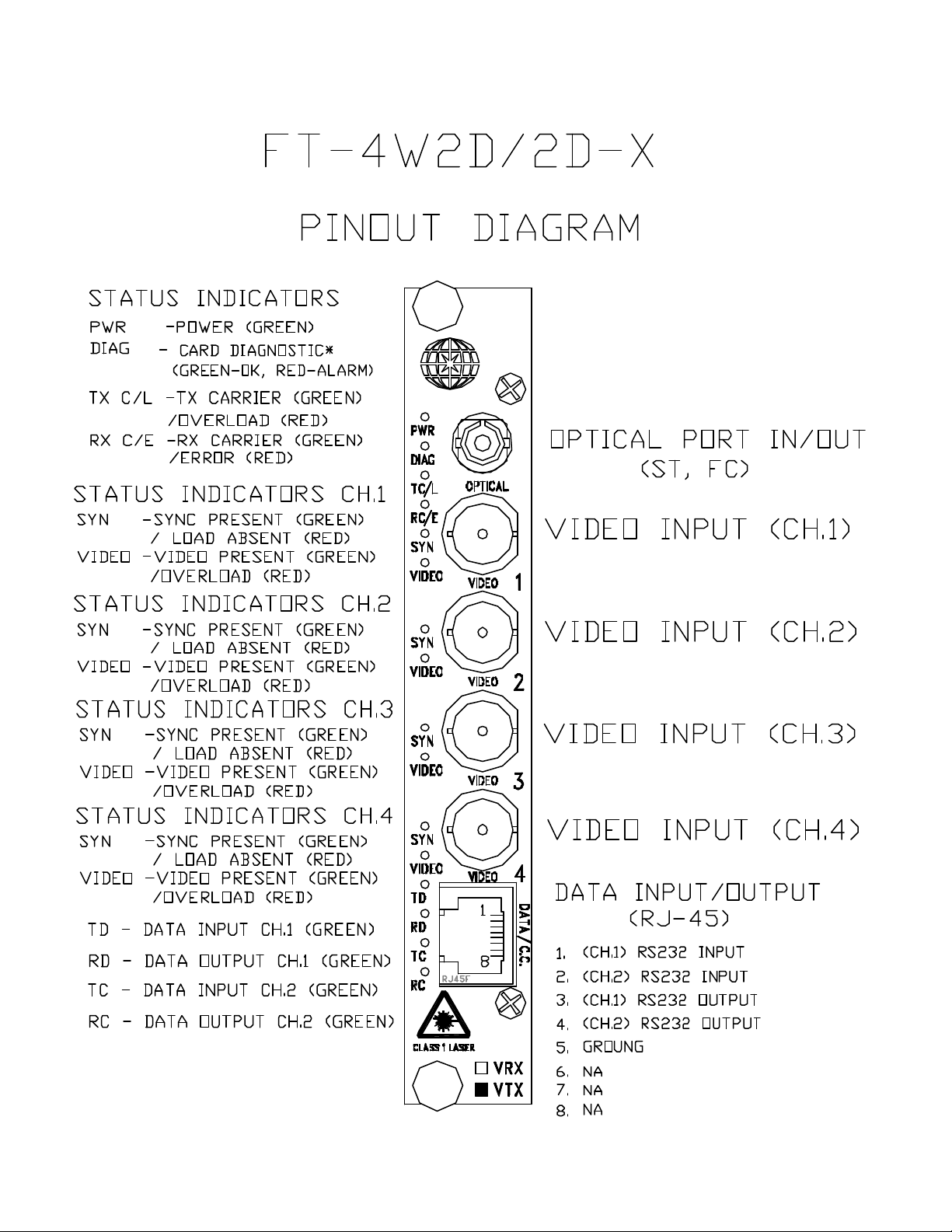
Figure 4.2
Figure 4.1
FT-4W2D/2D-x Front Panel Layout Diagrams
FR-4W1C1G/1C1G-x Front Panel Layout Diagram
Page 6
Page 7

Figure 4.2
FR-4W2D/2D-x Fro nt Panel Layout Diagrams
Page 7
Page 8

5.0 Signal Conditioning Switch/Jumper Settings
The sections below illustrate how to change the various contact mapping conditions.
For jumper and switch locations see Figure 5.2
5.1 Data Selection jumpers
There are four (4) 3-pin jumpers located directly behind the RJ45 front-panel mounted
connector.
The top 3 jumpers are used for 2 & 4-wire RS-485 selection and removing the default
120Ohm load on the RS-422 input channels.
The bottom jumper (Jp.4) used to select the power-on state of the contacts (NO or NC).
The illustration below describes the function of each of these 4 jumpers. The jumpers are
shown in their default condition in Table 1.
Page 8
Page 9

Figure 5.1
5.2 Data Format Selection
A group of 10 switches is located on the bottom center of the module’s circuit card (see
Figure 5.2). The left two (2) of these switches control the data format that is
transmitted/received. These switches on both the transmitter and receiver must be set
the same in order to have proper data communications format between them. FT and FR
modules can be configuring different for data format conversion (see Figure 5.1)
The figure and table below illustrates these switch locations on the board and how they
are configured for the proper data format options. The factory-supplied default setting
is for RS-232 data (Switch #1-2 OFF (up)).
Data Format Selection
RS-232 OFF (up) OFF (up)
Switches 3 and 4 should set by Meridian technician.
The illustration below describes the function of each of these switches.
Switch #1 Switch #2
Page 9
Page 10

Figure 5.2
1-Slot Module Data Format Selection Switch Location
Page 10
Page 11

6.0 SpectraViewTM Network Monitoring
The table below lists the function of each of these switches (numbered from left to right)
and identifies how to set the various diagnostic test modes.
Local
Test
Switch
SW1 – SW2 – Data format selection switches
SW5
SW6 OFF
SW7 OFF OFF
SW8 OFF OFF OFF
SW9 OFF OFF OFF OFF
SW10 OFF OFF OFF OFF OFF
Loop
Back
ON
Remote
Loop
Back
OFF OFF OFF OFF OFF
ON
Note: To turn a switch “ON”, move the switch in the down position. Likewise, to turn a
switch “OFF”, move it in the up position.
In order to enter the test modes on the module, it is necessary to actuate one of the above
switches as described below:
Transmit
Test
OFF OFF OFF OFF
ON
Receive
Test
OFF OFF OFF
ON
Spectra
View
Enabled
OFF OFF
ON
Reserved
OFF
OFF
Local Loopback test (SW5) -These tests will test all of the bi-directional data and contact
closures installed on the module associated with the loopback test. Obviously, the channels
that can be tested are determined by the type of channels associated with the particular
module under test.
The following procedures can be used to properly perform the loopback testing on both the
FT & FR series modules. Note that it is not necessary for both of the modules to be
connected via fiber in order to perform the Local Loopback tests.
Note: Local loopback test is not available for RS-485 (2-wire) configuration.
Data Test:
1. Place SW5 in the ON (down) position
2. Use Switches 1-2 to select the appropriate data format to be tested
3. Apply an appropriate digital signal into the respective data input connector
4. Connect a data-monitoring device (oscilloscope, BERT test equipment, etc.) to the
respective data output channel.
5. The output channel should be receiving the same data signal that was input to the
respective data input channel.
6. The front panel Data Transmit & Receive LEDs (TD & RD) on the module’s data
channel under test should light.
7. When complete, place SW5 in the OFF (up) position to return it to its normal
operating mode.
Page 11
Page 12

Remote Loopback Tests (S W6) -These tests will test all of the bi-directional data and
contact closures installed on the module associated with the remote loopback test.
Obviously, the channels that can be tested are determined by the type of channels
associated with the particula r module under test.
Note: Remote loopback test is not available for RS-485 (2-wire) configuration or
transmit/receive modules with a video channel.
The following procedures can be used to properly perform the loopback testing on both the
FT & FR series modules. In order to perform the remote loop back tests, it is necessary
to configure both the FT & FR modules as follows:
?? Both the FT & FR modules must be connected together via fiber and power
applied in order to perform the Remote Loopback tests.
?? When tes ting the data channels, it is necessary that the data formats for both the FT
& FR units be set the same (RS-232, RS-422, RS-485)
?? The Remote Loopback test switch (SW6) on the remote module must be in the ON
(down) position
?? Test switches (SW5-10) on the local unit must be in the OFF (up) position
Data Test:
1. Place SW6 on the remote unit in the ON (down) position
2. Use Switches 1-2 to select the appropriate data format to be tested.
3. Apply an appropriate digital signal into the respective data input connector on the
local unit (either Channel 1 or 2).
4. Connect a data-monitoring device (oscilloscope, BERT test equipment, etc.) to the
respective data output channel on the local unit.
5. The output channel should be receiving the same data signal that was input to the
respective data input channel.
6. The front panel Data Transmit LED (TD) on the transmit module’s data channel
under test should light as well as the Data Receive LED (RD) on the receiver
module’s front panel for each data channel under test.
7. When complete, pla ce SW6 on the remote unit in the OFF (up) position to return it to
its normal operating mode
Data/Contact Transmit Test (SW7) – (applicable to both full-duplex transceiver
modules and one-way data transmission modules) The type and quantity of channels that
can be tested are determined by the type of channels associated with the particular
module under test.
In order to perform the transmit test, it is necessary to configure both the modules as
follows:
?? The FT or FR modules must be connected together via fiber and power applied in
Page 12
Page 13

order to perform the Transmit tests.
?? When testing the data channels, it is necessary that the data formats for both the
modules be set the same (RS-232, RS-422, RS-485)
?? The Transmit Test switch (SW7) on the module initiating the test must be in the ON
(down) position
?? Test switches (SW5-10) on the local unit must be in the OFF (up) position
?? This test overrides any external data that may be at the input terminals of the unit
under test.
This test will inject the Data and Contact Closure test signals into the transmitter and will
be sent over fiber to the associated receiver module. This test will perform diagnostic
tests on all of the channels integrated in the module using the module’s own internal test
signals. In addition, the internal frequency/data rate of the various internal tests is as
follows:
Data - 1Hz square wave
Contact closure - 1Hz square wave
Once the Transmit test switch on the remote FT or FR module is switched ON, the above
signals will be transmitted over fiber to the receiving unit. The outputs can be
monitored by standard Data and Contact mapping measurement/monitoring techniques.
LED indicator status – During the test, the Tx channel indicator lights for the data and
contact mapping (TD & TC) on the module initiating the test will flash at a 1Hz rate. This
applies to each type and number of channels in the module. Likewise, each of the
channel’s front panel Rx channel indicator lights for the data and contact mapping (RD &
TC) on the receiver module’s front panel will flash at a 1Hz rate to indicate proper
reception of the test signals.
To disable the test, move SW7 on the FT or FR switch to the OFF position.
Data/Contact Receive Test (SW8) - (applicable to both full-duplex transceiver modules
and one-way receiver modules) These tests will test all of the data and contact closure
transmission channels installed on the module associated with the remote loopback test.
Obviously, the channels that can be tested are determined by the type of channels
associated with the particular module under test.
In order to perform the receive tests, it is necessary to configure both the modules as
follows:
?? The FR and FT modules do not need to be connected together via fiber.
?? The type of data output will be as per the data format sele ction switches 1 through
2 (RS-232, RS-422, RS-485)
?? The Receive Test switch (SW8) on the module initiating the test must be in the ON
(down) position
Page 13
Page 14

The receive test will perform diagnostic tests on all of the channels integrated in the
module using the module’s own internal test signals. The internal frequency/data rate of
the various internal tests is as follows:
Data - 1Hz square wave
Contact closure - 1Hz square wave
Once the Receive test switch on the FT or FR module is switched ON, the above signals
sent to the appropriate electrical outputs on the same module. These signal outputs can
be monitored by standard Data and Contact mapping measurement/monitoring
techniques.
LED indicator status – During the test, each of the channel’s front panel Rx channel
indicator lights for the data and contact mapping (RD & TC) on the receiver module’s front
panel will flash at a 1Hz rate to indicate proper reception of the test signals. This applies to
each type and number of channels in the module.
To disable the test, move SW7 on the FR or FT switch to the OFF position. This will
restore operation to its normal mode.
Video Test – (Applicable to one-way transmission modules (FT & FR units). This video
test mode will allow the user to test the video transmission channel without the use of an
external camera to generate a video signal.
There are two video tests available – Transmit video & Receive video. The following
describes the test setup for each:
Transmit video test – This test injects a 4-bar video test pattern into the video transmitter
and sends this signal over fiber to the associated receiver module.
In order to initiate the internal transmit video test it is necessary to configure the modules
as follows:
?? SW7 on the FT video Tx module must be set to the ON (d own) position.
?? SW8 on the FR video Rx module must be set to the OFF (up) position.
?? The optical fiber between the FT & FR modules must be connected together
?? Connect a standard video monitor to the output of the FR (Video Receiver) module
?? 4 grey-scale vertical bars will be displayed on the monitor
?? Receiver module LEDs – If a video monitor is not available, the activity of the
transmit video test can be monitored on the receiver’s front panel LEDs. When
this test is activated, the receiver modules Video Sync & Video Present green
LEDs (SYN & VIDEO) will light.
Receive video test – This test injects an 8-bar video test pattern into the video receiver
and sends it to the receiver output BNC for display on a video monitor.
Page 14
Page 15

In order to initiate the internal receiv e video test it is necessary to configure the modules
as follows:
?? SW7 on the FT video Tx module must be set to the OFF (up) position.
?? SW8 on the FR video Rx module must be set to the ON (down) position.
?? The optical fiber between the FT & FR modules must be connected together
?? Connect a standard video monitor to the output of the SR (Video Receiver) module
?? 8 grey-scale vertical bars will be displayed on the monitor
SpectraView Enabled (SW9) - (Applicable to one-way transmission modules with
video (FT & FR units). This video mode will enable the vertical video bars to be
displayed in the event that either the incoming video signal has been removed or if the
optical signal from the transmitter has been interrupted.
To enable this video bars feature it is necessary to configure the modules as follow:
?? SW 9 on the FR (video Receiver) module must be set to the ON (down) position
?? SW 9 on the FT (video Transmitter) module must be set to the ON (down) position
Under normal operation, the video from the CCTV camera will be displayed on the
respective monitor at the receive side. There are two ‘alarm’ modes - one for loss of
video sync and one for loss of optical signal. When one or the other of these alarm
modes is present, the monitor will display the following:
Loss of video sync - 4 vertical gray-scale bars across the monitor screen
Loss of optical signal - 8 vertical gray-scale bars across the monitor screen
Note: Modules equipment with Meridian’s SpectraSmart Network Diagnostic System
option will have a slightly different video display. Instead of the vertical bars, the monitor
will actually display a text message (as described below):
Loss of video sync error: will display the message “No Video Sync”
Loss of Optional signal error: will display – “No Optical Fiber”
This procedure concludes the testing of the video/data/contact channels within Meridian’s
DigiCool (1-slot) fiber optic digitally -encoded transmission modules.
Page 15
Page 16

7.0 Product Part Numbers
The table below lists the various part numbers and description that are available for this
series of product.
Product Part Number Guide
Part Number Matching Part #
FT-2W2D/2D-2 FR-2W2D/2D-2 2 Multimode ST
FT-2W2D/2D-5 FR-2W2D/2D-5 2 Singlemode FC
FT-2W2D/2D-5ST FR-2W2D/2D-5ST 2 Singlemode ST
FT-4W2D/2D-2 FR-4W2D/2D-2 4 Multimode ST
FT-4W2D/2D-5 FR-4W2D/2D-5 4 Singlemode FC
FT-4W2D/2D-5ST FR-4W2D/2D-5ST 4 Singlemode ST
Video
channel
Fiber
Interface
Optical
Connector
Note: This FT & FR series cards are not compatible with the other 1-slot ST & SR
cards.
8.0 Troubleshooting
Below is a listing of several problems that may arise during the installation & operation of
the modules. If you are having difficulty installing or operating the modules please refer
to this list below.
Problem: Module does not fit in chassis slots
Action: Check module orientation. Meridian “Globe” must be oriented on the top left
hand side of the module. Make sure the card guides in the chassis are aligned
with the extrusion on the module.
Problem: Card power LED does not light when power to the module/subrack is
applied or power indicator turns on and off
Action: Check power supply to ensure that it is plugged in and turned on. If flashing
continues, move module to another chassis or location in the same chassis, if
available.
Problem: No video at output of module
Action: Check the SpectraView display on the monitor for an indication of what the
problem may be. Also, check to ensure that the video channel-specific LEDs are
on (Green). Also, check to ensure that the optical LEDs are ON. If no video is
Page 16
Page 17

still present, check to ensure that the monitor is ON and the video cable is
connected to the correct video port on the Rx module.
Problem: Video image is dark
Action: Check the iris control on the camera to ensure that it is open to the proper
amount for the conditions.
Problem: Video image is too bright and appears overexposed
Action: Check the Video overload indicator on the Rx module. If it is Red, the
video signal level is too high and the CCTV iris should be check ed to ensure
that it is open properly for the conditions.
Problem: No Data
Action: Check that both transmit and receive modules is set to transmit/receive the
same data format (see section 5.0 for switch settings). Confirm that the data
connections are correct (see section 4.0 for data pinout connections). Check
to ensure that the data source is operating properly.
If the problem still persists after reviewing the above items, please contact Meridian
technical support (516- 285-1000).
Notes:
Page 17
Page 18

Meridian Technologies, Inc.
700 Elmont Road, Elmont NY 11003
Telephone: 516-285-1000 Fax: 516-285-6300
E-mail: sales@meridian-tech.com
Web: www.meridian-tech.com
Document Version 1
05/29/2013
Page 18
 Loading...