

Page 1
MERIDIAN DSP
LOUDSPEAKER
USER GUIDE
Page 2

i
Meridian DSP Loudspeaker User Guide
Subtitle
Off
EnterReturn
Function 0Title
Chapter
Record
Slow
OSD
T
Angle Audio A-B Phase
Setup
Band
789
456
123
Menu Volume
Display
Mute
Preset
Clear
Store
Repeat
CD RADIO LP TV TAPE 1 TAPE 2 CDR CABLE
DVD
VCR 1 VCR 2 LD
Page 3
ii
PREFACE
Boothroyd|Stuart Meridian, Meridian,
Meridian Digital Theatre, Meridian
Lossless Packing, MHR and MLP are
registered trademarks of Meridian
Audio Ltd.
MHR: This product incorporates
copyright protection technology covered
by certain patent applications and
intellectual property of Meridian Audio
Ltd. This technology is provided for the
express purpose of securely containing
copyright audio within the Meridian
System only. Reverse engineering or
circumvention of this protection is
strictly prohibited.
FCC Warning: This equipment
generates and can radiate radio
frequency energy and if not installed
Copyright and acknowledgements
Sales and service in the UK
Meridian Audio Ltd
Stonehill
Stukeley Meadows
Cambs
PE29 6EX
England
Tel (01480) 445678
Fax (01480) 445686
Sales and service in the USA
Meridian America Inc
3800 Camp Creek Parkway
Building 2400
Suite 122
Atlanta
GA 30331
Tel (404) 344 7111
Fax (404) 346 7111
World Wide Web – http://www.meridian-audio.com
Designed and
manufactured in the UK by
Meridian Audio Ltd
Stonehill
Stukeley Meadows
Cambs
PE29 6EX
England
Copyright © 2001 Meridian Audio Ltd.
Part no: DSPU/1
and used correctly in accordance with
our instructions may cause interference
to radio communications or radio and
television reception. It has been type-
tested and complies with the limits set
out in Subpart J, Part 15 of FCC rules for
a Class B computing device. These limits
are intended to provide reasonable
protection against such interference in
home installations.
EEC: This product has been designed
and type-tested to comply with the
limits set out in EN55013 and EN55020.
This guide was produced by:
Human-Computer Interface Ltd,
http://www.interface.co.uk
Page 4

Contents
iii
Introduction 1
Meridian DSP loudspeakers 2
Sample configurations 5
Specification – DSP5000 and DSP5000C 6
Specification – DSP5500, DSP5500HC, and
DSP5500C 8
Specification – DSP6000 and DSP6000C 10
Available accessories 12
Setting up the DSP
loudspeakers 13
Unpacking 14
Positioning the digital loudspeakers 18
Connecting the loudspeakers 19
Connecting to other equipment 20
Using the DSP
loudspeakers 23
Selecting a source 24
Changing the display 25
Adjusting the volume 26
Changing the treble, bass or phase 27
Changing the listening position 28
Configuring the DSP
loudspeakers 29
Choosing standard settings 30
Specifying information about your system 32
Configuring the sources 33
Configuring the setup options 35
Page 5

iv
Troubleshooting 37
Troubleshooting 38
Cleaning 40
Service and guarantee 41
Index 43
Page 6

1
Subtitle
Off
EnterReturn
Function 0Title
Chapter
Record
Slow
OSD
T
Angle Audio A-B Phase
Setup
Band
789
456
123
Menu Volume
Display
Mute
Preset
Clear
Store
Repeat
CD RADIO LP TV TAPE 1 TAPE 2 CDR CABLE
DVD
VCR 1 VCR 2 LD
Introduction
Welcome to the Meridian DSP loudspeaker range!
This User Guide provides full information about using the DSP
loudspeakers in conjunction with your other equipment, to achieve the
superb results you can expect from them.
Page 7

2
INTRODUCTION
Meridian DSP loudspeakers
Meridian DSP loudspeakers represent the fruits of more than 25 years of
continuous development of loudspeakers as musical instruments. The finest
materials and state-of-the-art design are combined to create what we
believe is the ultimate range of home loudspeakers.
Digital Signal Processing
Digital Signal Processing, or DSP, is a technique pioneered by Meridian in
hi-fi products for achieving extremely accurate reproduction of audio
signals using high-precision mathematical processing.
DSP allows sophisticated processing to be performed without any of the
cumulative noise or degradation that inevitably occurs, even with highquality analogue circuitry. In addition, the signal improvement techniques
incorporated in the Meridian DSP loudspeakers would be virtually
impossible to implement in analogue circuitry.
The Meridian DSP loudspeakers take advantage of DSP for several different
functions:
•
To remove timing variations from the incoming digital signals
(de-jittering).
•
To split the frequency band between bass, mid-range, and treble drivers
(crossover).
•
To perform filtering or adjustment of the frequency response; eg treble
or bass.
•
To provide volume control to 48-bit precision.
•
To provide digital protection of the loudspeakers against high-level lowfrequency transients.
•
To perform electronic equalisation.
If you are using the Meridian DSP loudspeakers with a digital source, such
as CD or DVD, the signals remain in digital form until the last possible
stage.
DSP loudspeaker drivers
Each DSP loudspeaker uses multiple high-efficiency long-throw custom
drive bass units.
Each treble unit is a very high quality 25mm (1") Meridian piston in a short
horn, using an aluminium dome with a silver voice-coil. It is extremely well
matched to the woofers, and also tonally very compatible with the other
speakers in the Meridian range.
Page 8

3
INTRODUCTION
Power amplifiers
The speakers are driven by multiple independent high-power, lowfeedback power amplifiers. The combination of idealised magnetic design,
careful star earthing, and very fast output devices gives the amplifiers
extremely low noise, high detail, and fast bass.
The whole electronic assembly is supplied from substantial toroidal
transformers feeding high-quality, audiophile-grade capacitors.
Cabinet
Each DSP loudspeaker is carefully designed with internal bracing and
damping to give incredibly low levels of cabinet resonance, resulting in low
colouration and excellent mid-range transparency.
The DSP5500, DSP5500C, and DSP5500HC are constructed using thick
veneered MDF sides bolted through a 1.5mm steel plate onto the main
cabinet, giving extremely low levels of cabinet resonance and excellent
bass-mid isolation.
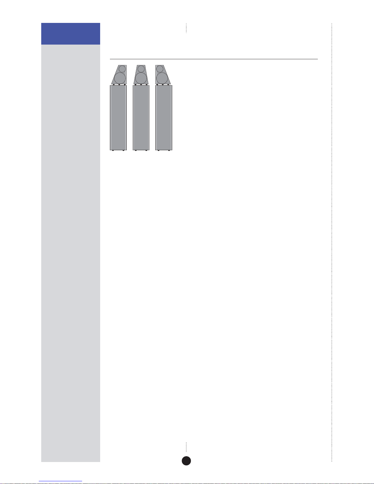
In the DSP6000 and DSP6000C the bass drivers are mounted symmetrically
in pairs on the sides of the cabinet, cancelling vibration and giving
exceptionally low levels of cabinet resonance. The mid-range and treble
drivers are housed in a separate interlaminated head, to minimise bass-mid
interference. It is supported on the bass enclosure by three machined feet.
Mounting options
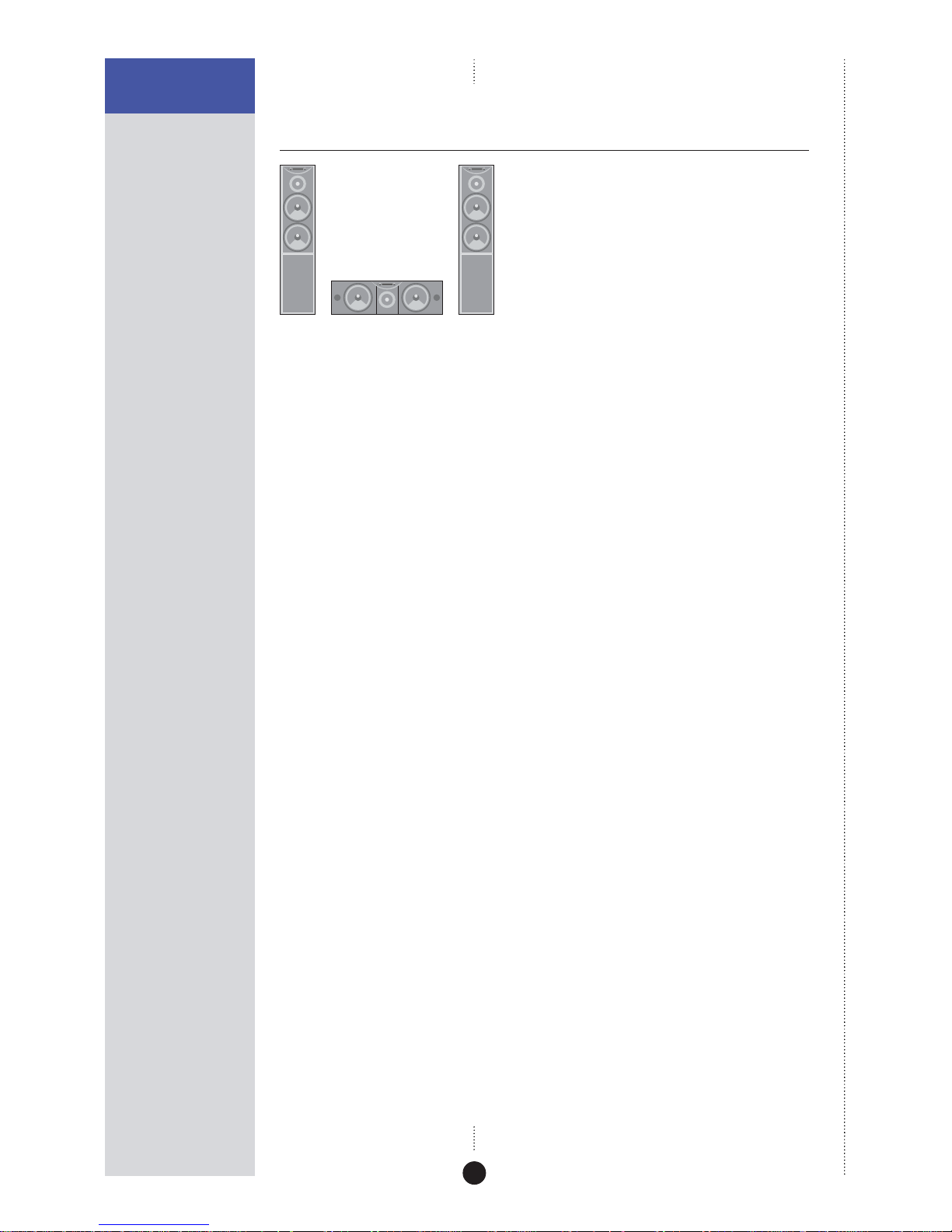
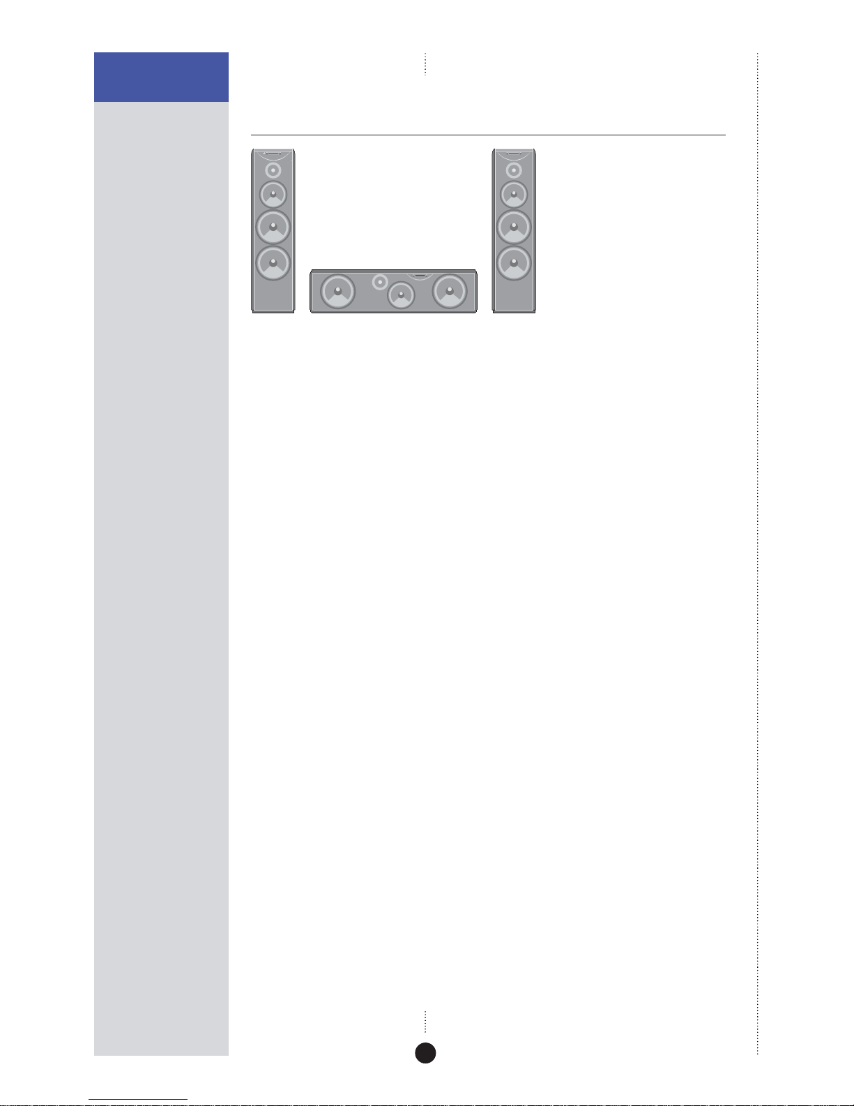
The DSP5000 and DSP5500 are available in horizontal centre versions,
designed for use either above or below a television.
The DSP5000C and DSP6000C head units use fully shielded drive units so
that they can be placed next to a television without interference.
Meridian High Resolution (MHR)
All Meridian DSP loudspeakers support Meridian High Resolution (MHR), to
allow you to connect to other MHR-compliant Meridian products to take
advantage of high-rate audio sources, and provide the additional benefits
of lower jitter and improved sound quality on all sources.
MHR is a proprietary secure encoding format that uses encryption and anticopy methods to provide a secure copyright protection environment, and
allow the secure transfer of audio streams within a Meridian-only system
for playback only.
Page 9

4
INTRODUCTION
Meridian Comms
The Meridian DSP loudspeakers are part of the Meridian family of
advanced digital, analogue, and video components, and these incorporate
a sophisticated communications link, to allow you to control any
combination of units using a single remote, and ensure that they will work
together as a fully integrated system.
The communications system also allows you to extend your hi-fi system into
two or three rooms, with the ability to control the sources in one room
from the controller in another room.
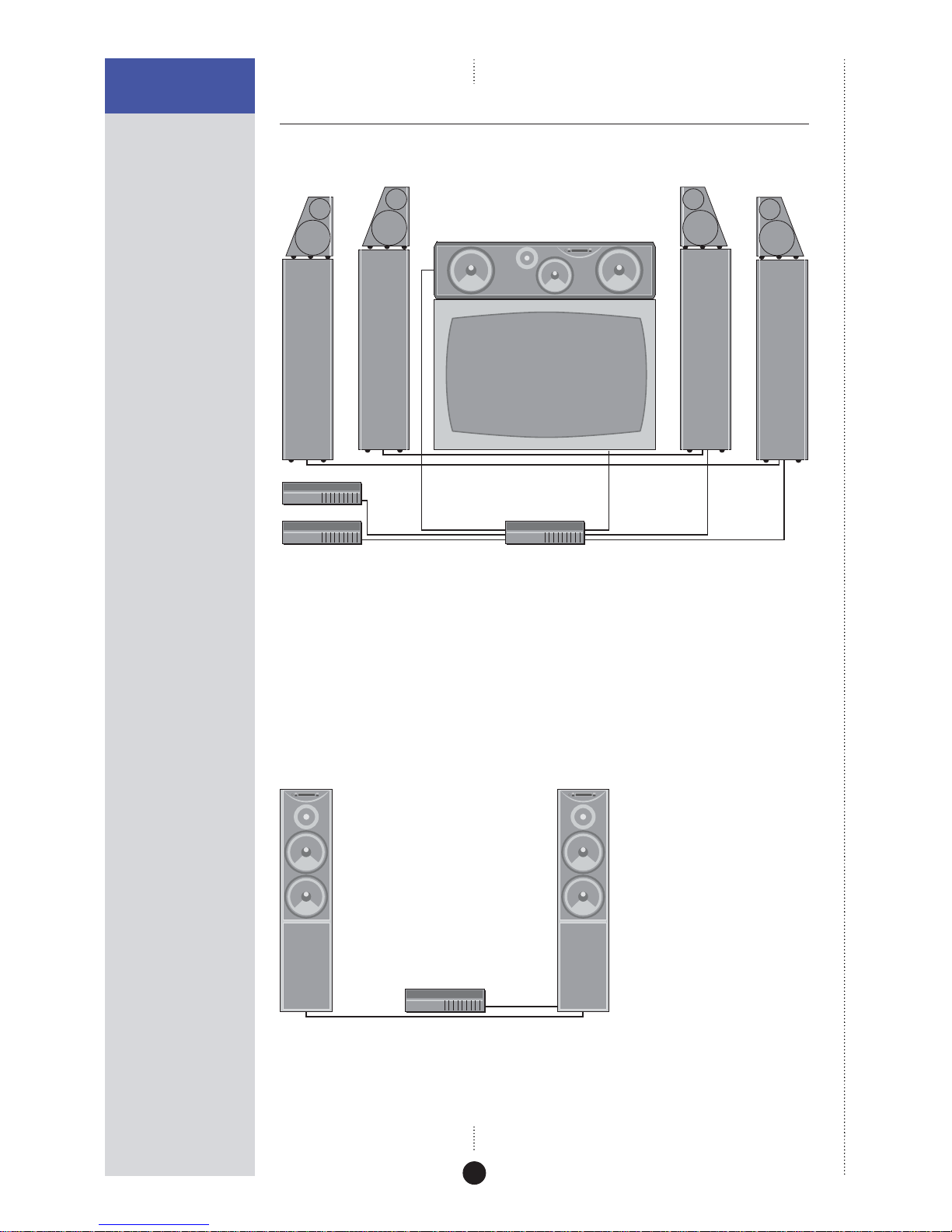
The following page shows two recommended configurations based on the
Meridian DSP loudspeakers to illustrate the flexibility of Meridian
components.
Page 10
5
INTRODUCTION
Sample configurations
Meridian Digital Theatre™
Meridian DVD Player
DSP5500HC
504
Meridian Surround Processor
DSP6000 DSP6000
DSP6000DSP6000
Up to seven Meridian DSP loudspeakers can be used in conjunction with a
Meridian Surround Processor to create a digital surround system with
superb music and cinema sound.
The Meridian DVD Player is an ideal source for use with DSP loudspeakers.
It allows you to play both audio CDs and DVD movies, with the audio kept
in digital form until the last possible stage.
Meridian Digital Music System
Meridian CD Player
DSP5000 DSP5000
Meridian DSP loudspeakers include DSP volume and tone controls, and can
be connected directly to up to two digital sources to create an extremely
compact high-quality music system.
Page 11
6
INTRODUCTION
Specification – DSP5000 and
DSP5000C
Digital inputs and outputs
•
2 x cable inputs, 32-192kHz. FIFO locks at 44.1, 48, 88.2, 96, 176.4, or
192kHz ± 150ppm (176.4 and 192kHz supported by single wire
connection and future software upgrade).
•
PCM using IEC958, or MHR connection support with auto-detection.
•
1 x cable input pass-through to feed second speaker.
Signal processing
•
1 x Motorola 56303 running at 80MHz.
•
2 x 24-bit Multi-bit delta-sigma DACs with 128x oversampling.
•
Crossover linear-phase ±30º at 2.3kHz.
Output stages
•
Power amplifiers: Complementary bipolar design, with output-stage
error correction and twin loop design.
•
Bass: 2 x 75W.
•
Treble: 75W.
Acoustic
•
2 way.
•
Ported bass enclosure.
•
Bass/Mid drive units: 2 x 160mm (6") polypropylene high-efficiency
long-throw custom drivers.
•
Treble drive unit: 1 x 25mm (1") Meridian piston in short horn,
aluminium dome with silver voice-coil.
Characteristics
•
Distortion typically <0.01%, or <0.02% up to full power at all
frequencies.
•
Noise and hum <-94dBr at all volume settings.
•
Acoustic output typically >108dB spl @ 1m.
•
Acoustic noise <15dB spl @ 1m.
•
Frequency response in room response within 3dB, 35Hz-20kHz.
Page 12

7
INTRODUCTION
Control
•
2 x Meridian Comms.
•
9-pin D connector for RS232 PC control, null modem, 9600 baud, 2N1, no
handshake.
Cabinet
•
Wood-veneered MDF with internal bracing and damping.
•
Available in black ash, rosewood, and cherry.
•
DSP5000: 210mm x 900mm x 297mm (8.3" x 35.4" x 11.7") (W x H x D).
•
DSP5000C: 670mm x 195mm x 275mm (26.3" x 7.7" x 10.8") (W x H x D).
•
32kg (70lb) each.
Power
•
100-125; 200-250V AC 50-60Hz.
•
20VA standby; 300VA max.
Meridian Audio reserves the right to amend product specifications at any
time.
Page 13
8
INTRODUCTION
Specification – DSP5500,
DSP5500HC, and DSP5500C
Digital inputs and outputs
•
2 x cable inputs, 32-192kHz. FIFO locks at 44.1, 48, 88.2, 96, 176.4, or
192kHz ± 150ppm (176.4 and 192kHz supported by single wire
connection and future software upgrade).
•
PCM using IEC958, or MHR connection support with auto-detection.
•
1 x 24-bit Multi-bit delta-sigma DACs with 128x oversampling.
Signal processing
•
2 x Motorola 56303 running at 80MHz.
•
4 x 24-bit Multi-bit delta-sigma DACs with 128x oversampling.
•
Crossover linear-phase ±30º at 200Hz and 2.6kHz.
Output stages
•
Power amplifiers: Complementary bipolar design, with output-stage
error correction and twin loop design.
•
Bass: 2 x 75W.
•
Mid: 75W.
•
Treble: 75W.
Acoustic
•
3 way.
•
Ported bass enclosure.
•
Isolated mid enclosure.
•
Bass drive unit: 2 x 200mm (8") high-efficiency long-throw custom
drivers.
•
Mid drive unit: 1 x 160mm (6") custom polypropylene driver using phase
plug.
•
Treble drive unit: 1 x 25mm (1") Meridian piston in short horn,
aluminium dome with silver voice-coil.
Page 14

9
INTRODUCTION
Characteristics
•
Distortion typically <0.01%, or <0.02% up to full power at all
frequencies.
•
Noise and hum <-94dBr at all volume settings.
•
Acoustic output typically >111dB spl @ 1m.
•
Acoustic noise <15dB spl @ 1m.
•
Frequency response in room response within 3dB, 28Hz-20kHz.
Control
•
2 x Meridian Comms.
•
9-pin D connector for RS232 PC control, null modem, 9600 baud, 2N1, no
handshake.
Cabinet
•
Thick MDF side panels sandwiched around steel plates for maximum
damping across all frequencies.
•
Steel plates give magnetic shielding.
•
Side panels available in black ash and rosewood.
•
Separate mid-range enclosure built into main cabinet.
•
DSP5500 and DSP5500C: 284mm x 1100mm x 450mm (11.2" x 43.3" x
17.7") (W x H x D).
•
DSP5500HC: 1100mm x 285mm x 415mm (43.3" x 11.2" x 16.3")
(W x H x D).
•
65kg (143lb) each.
Power
•
100-125; 200-250V AC 50-60Hz.
•
20VA standby; 600VA max.
Meridian Audio reserves the right to amend product specifications at any
time.
Page 15
10
INTRODUCTION
Specification – DSP6000 and
DSP6000C
Digital inputs and outputs
•
2 x cable inputs, 32-192kHz. FIFO locks at 44.1, 48, 88.2, 96, 176.4, or
192kHz ± 150ppm (176.4 and 192kHz supported by single wire
connection and future software upgrade).
•
PCM using IEC958, or MHR connection support with auto-detection.
•
1 x 24-bit Multi-bit delta-sigma DACs with 128x oversampling.
Signal processing
•
2 x Motorola 56303 running at 80MHz.
•
4 x 24-bit Multi-bit delta-sigma DACs with 128x oversampling.
•
Crossovers linear-phase ±30º at 200Hz and 2.6kHz.
Output stages
•
Power amplifiers: Complementary bipolar design, with output-stage
error correction and twin loop design.
•
Bass: 2 x 75W.
•
Mid: 75W.
•
Treble: 75W.
Acoustic
•
3 way.
•
Separate mid/top plywood cabinet.
•
Bass drive unit: 4 x 200mm (8") high-efficiency long-throw custom
drivers.
•
Mid drive unit: 1 x 160mm (6") custom polypropylene driver using phase
plug.
•
Treble drive unit: 1 x 25mm (1") Meridian piston in short horn,
aluminium dome with silver voice-coil.
Page 16

11
INTRODUCTION
Characteristics
•
Distortion typically <0.01%, or <0.02% up to full power at all
frequencies.
•
Noise and hum <-94dBr at all volume settings.
•
Acoustic output typically >112dB spl @ 1m.
•
Acoustic noise <15dB spl @ 1m.
•
Frequency response in room response within 3dB, 25Hz-20kHz, lower at
moderate volumes.
Control
•
2 x Meridian Comms.
•
9-pin D connector for RS232 PC control, null modem, 9600 baud, 2N1, no
handshake.
Cabinet
•
Head enclosure manufactured from interlaminated panels with internal
damping and bracing.
•
Glass front.
•
Head finished in high-gloss black piano lacquer.
•
275mm x 1330mm x 425mm (10.8" x 52.4" x 16.7") (W x H x D).
•
9.5kg (21lb) each.
Power
•
100-125; 200-250V AC 50-60Hz.
•
6VA idle; 200VA max.
Meridian Audio reserves the right to amend product specifications at any
time.
Page 17

12
INTRODUCTION
Available accessories
Each DSP loudspeaker is shipped complete with cables to enable it to be
used in a Meridian Digital music system. In addition, each pair of main
loudspeakers is supplied with a Meridian System Remote.
Other applications, and some advanced features, may require one or more
of the following accessories, which can be purchased from your Meridian
dealer:
•
Additional S5 leads (8m and 14m).
•
511 S-patch box if connecting more than two DSP loudspeakers to a 561
Digital Surround Controller or 568 Digital Surround Processor (not
required with 861).
Page 18

13
Subtitle
Off
EnterReturn
Function 0Title
Chapter
Record
Slow
OSD
T
Angle Audio A-B Phase
Setup
Band
789
456
123
Menu Volume
Display
Mute
Preset
Clear
Store
Repeat
CD RADIO LP TV TAPE 1 TAPE 2 CDR CABLE
DVD
VCR 1 VCR 2 LD
Setting up the DSP loudspeakers
This chapter explains how to install your DSP loudspeakers. It
describes what you should find when you unpack the speakers, how
you should connect them to your other audio equipment, and the
siting constraints.
Page 19

14
SETTING UP THE DSP
LOUDSPEAKERS
Unpacking
Before you begin installation you should ensure that your DSP
loudspeakers are the correct voltage for your local AC supply. If they are
not, do not try to install them, and contact your dealer.
You should not make any connections to the DSP loudspeakers, or to any
other component in your system, while the AC power supply is connected
and switched on.
Care when unpacking
Take great care when unpacking or re-packing the DSP loudspeakers that
you do not put undue pressure on the face containing the drive units, as
they may be damaged if pressed.
Components
Each pair of DSP loudspeakers is supplied with the following components:
•
The DSP loudspeakers complete with grilles.
•
Eight screw-in spikes with lock nuts and foot caps (except DSP5000C and
DSP5500HC).
•
Eight rubber bumpons (DSP5000C and DSP5500HC).
•
A wrench for the spikes.
•
A hex wrench (3mm) for the drive units.
•
Meridian System Remote, battery and user guide.
•
One power cord per speaker.
•
Meridian M5 lead (8m).
•
Meridian S5 lead (8m).
•
This user guide.
The following specific speakers include additional components:
DSP5500, DSP5500C, and DSP5500HC
•
A hex wrench (8mm) for the side panels.
DSP6000 and DSP6000C
Each speaker is supplied with:
•
A head unit complete with cups.
•
Three knurled screw-in pillars for the head unit to sit on.
•
Three plastic spacers to fit over the pillars.
•
A head connection lead.
•
A top glass plate for the base unit.
If any of these items is missing, please contact your dealer. We suggest that
you retain the packaging carefully for maximum protection in transit.
Page 20

15
SETTING UP THE DSP
LOUDSPEAKERS
Caution (DSP6000 and DSP6000C only)
Meridian Audio has taken every care in the design, assembly, finishing and
packing of this product. The high gloss finish on parts of the cabinet is
achieved by painting up to five coats of polyester lacquer onto the
plywood, each one hand polished.
Due to the product size and high technology cabinet construction, small
marks on the lacquer surface may be visible when unpacked. These small
marks can usually be removed as described in Cleaning, page 40.
It is the nature of all lacquer finishes to shrink over time. This is
unavoidable and may result in cabinet joint lines becoming visible.
Meridian Audio has supplied products using lacquer finishes for many years
and we are confident that when carefully used your product will return a
lifetime’s enjoyment.
Tightening the drive units
The DSP loudspeakers typically take about two weeks of normal use for the
drive units to settle. It is therefore recommended that you tighten the
mounting bolts on each drive unit every few days during this period.
Tighten the bolts in symmetrically opposite pairs using the 3mm hex
wrench supplied.
Note (DSP5500): The DSP5500 grille frame has been designed to be as
acoustically transparent as possible, and is quite fragile. When removing
the grille, ease it carefully off by hand from the bottom and sides, avoiding
excessive bending of the frame.
You should then check and if necessary retighten the drive units every few
years.
To fit the feet (except DSP5000C and DSP5500HC)
The feet ensure that the loudspeakers have a stable base, and can be
adjusted to allow for uneven floors. Use the spikes for carpeted floors; they
are designed to penetrate the pile without damaging or flattening the
carpet.
Each DSP loudspeaker needs four feet, fitted as follows:
• Fit a lock nut to each spike, leaving about 2mm of thread between the
lock nut and spike. If a foot is required rather than a spike, fit a foot
cap. Screw each foot into the threads on the bottom of the base units.
Do not fully tighten the foot at this stage.
Page 21

16
SETTING UP THE DSP
LOUDSPEAKERS
• When all four feet have been fitted, carefully set the DSP loudspeakers
upright in their playing positions and remove the rest of the packaging.
To fit the rubber bumpons (DSP5000C and DSP5500HC
only)
• Attach four bumpons to the underside of each speaker, using the selfadhesive pads.
To install the head units (DSP6000 or DSP6000C only)
• Locate the three pillars and screw them into the three holes in the top
of each base unit.
• Fit the glass plate over the pillars on the top of each base unit.
• Fit a plastic spacer over each pillar.
• Place the head unit on top of each base unit.
On the DSP6000 the gold stripes on the head and base units should line up.
The speakers have the correct orientation if the sloping sides on the heads
are to the outside (gold strip inside).
• Connect the end of each head connection lead marked with a red band
to the socket in the back of the head unit.
• Connect the other end of each lead to the socket on the back of the
base unit.
To dismantle the loudspeakers (DSP6000 or DSP6000C
only)
When dismantling the speakers always switch off and disconnect the power
first, then disconnect the head unit from the base unit.
Note: Do not disconnect the head lead while the unit is connected
to the AC supply and switched on.
It is advisable to remove the head units when moving the speakers. This is
achieved by disconnecting the head lead from the base unit and lifting off
the head. Take care while the head is not in position as this exposes its
mounting spikes. While not in place the head should be stored safely but
care should also be taken of the surface they are placed upon as it may be
damaged by the cups.
Page 22
17
SETTING UP THE DSP
LOUDSPEAKERS
Radio interference
FCC Warning: This equipment generates and can radiate radio frequency
energy and if not installed and used correctly in accordance with our
instructions may cause interference to radio communications or radio and
television reception. It has been type-tested and complies with the limits
set out in Subpart J, Part 15 of FCC rules for a Class B computing device.
These limits are intended to provide reasonable protection against such
interference in home installations.
EEC: This product has been designed and type-tested to comply with the
limits set out in EN55013 and EN55020.
Page 23

18
SETTING UP THE DSP
LOUDSPEAKERS
Positioning the digital loudspeakers
Safety warnings
•
Do not expose the speakers to dripping or splashing.
•
Do not place any object filled with liquid, such as a vase, on the
speakers.
•
Do not place naked flame sources, such as lighted candles, on the
speakers.
To avoid overheating
Do not position the speakers:
•
In direct sunlight.
•
Near heat sources, such as a radiator.
•
Directly on top of heat producing equipment.
The back panel of the DSP loudspeaker acts as a heatsink and requires
adequate ventilation. Ensure that air can flow around it.
The back panel normally runs warm to the touch even when the speakers
are silent.
To obtain the best sound
For best results adjust the position of the loudspeakers while listening to
music.
If possible, have the most acoustically absorbent wall in the room behind
the front speakers. Ideally have each DSP loudspeaker at least 0.5m (20")
from a corner, and position them approximately 0.25m (10") from the wall.
If you are using a DSP loudspeaker as a centre channel, place the speaker
centrally between the main left-right pair and, if possible, arrange for the
treble units of the three speakers to be approximately the same height.
You can configure the frequency response of the DSP loudspeakers to
compensate for a position close to a wall or corner; see To adjust the
frequency response, page 35.
Page 24
19
SETTING UP THE DSP
LOUDSPEAKERS
Connecting the loudspeakers
Back panel
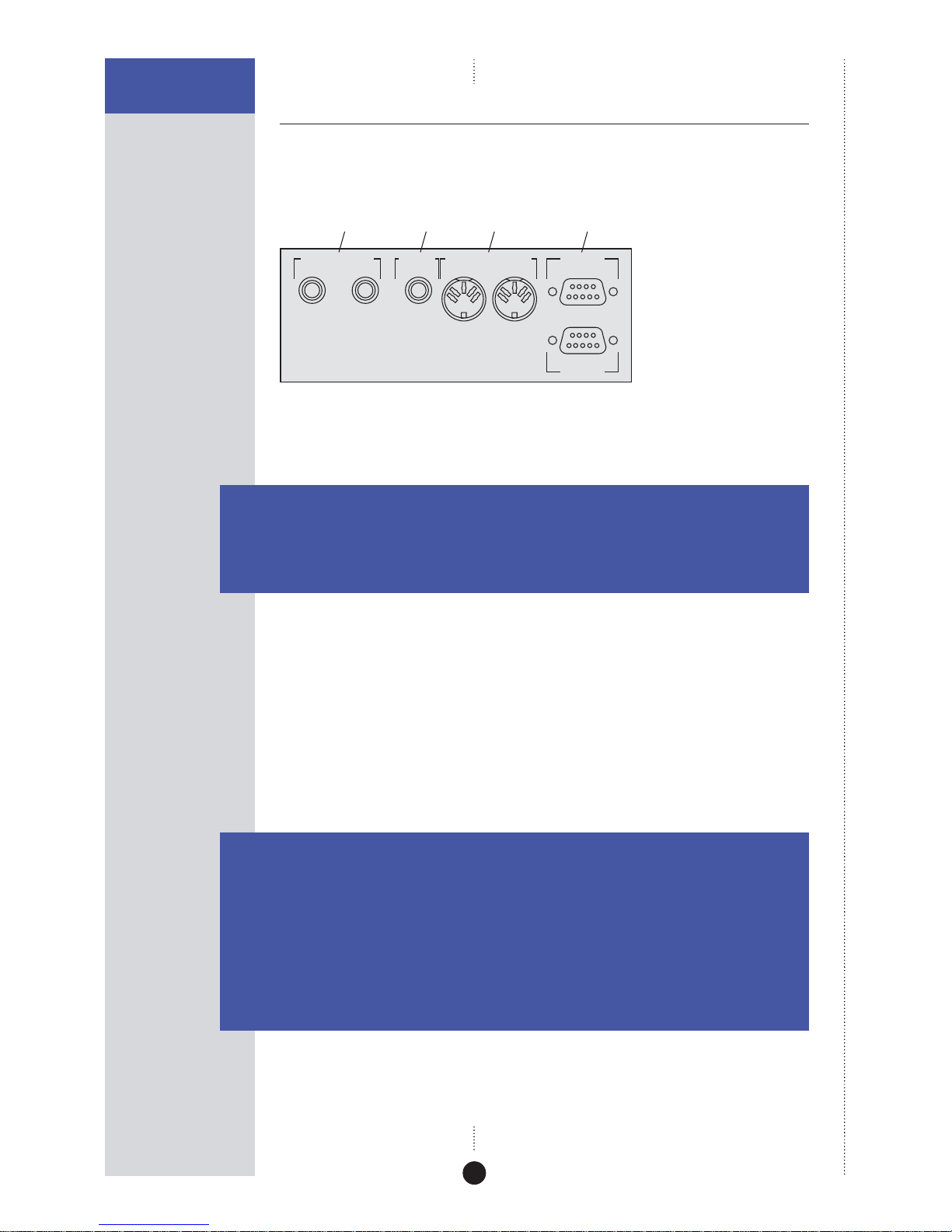
The following diagram gives details of the back panel connections:
MERIDIAN COMMS RS232
OUTPUT INPUT
DIGITAL INPUT DIGITAL
OUTPUT
21
EXPANSION
Comms
Digital
inputs
Digital
output
PC
Digital connections
The following table gives details of the digital audio connections:
Use this connection To connect to this
DIGITAL INPUT 1, A digital source, such as a digital sound processor,
DIGITAL INPUT 2 digital preamplifier, CD player, or DVD player.
DIGITAL OUTPUT A second (slave) DSP loudspeaker, using an S5 lead.
The digital connections should be made with high-quality 75Ω screened
cable. Suitable cables are available from Meridian. We do not recommend
using audio cables, which do not have adequate shielding or the correct
impedance, or cables intended for UHF applications, as these do not
provide adequate shielding in the 1–30MHz region.
Communications connections
The following table gives details of the communications connections:
Use this connection To connect to this
COMMS INPUT The COMMS connection on a Meridian control unit or
preamplifier.
COMMS OUTPUT The COMMS INPUT on a second DSP loudspeaker.
RS232 The serial port of a PC, to control the DSP loudspeaker using a
computer. For more information see the Meridian Web site,
http://www.meridian-audio.com.
EXPANSION For future expansion.
Page 25
20
SETTING UP THE DSP
LOUDSPEAKERS
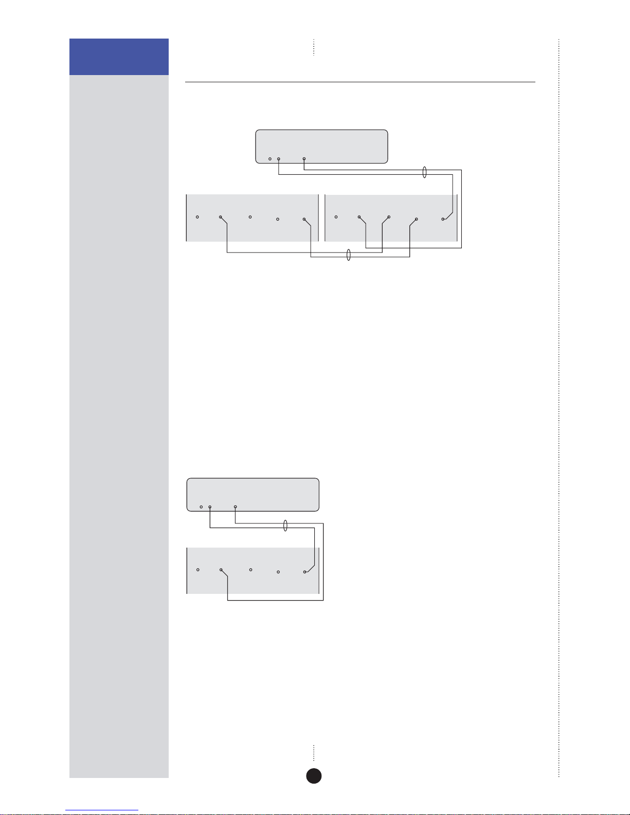
Connecting to other equipment
To connect two DSP loudspeakers in a Meridian system
DIGITAL
OUTPUT
COMMS
S5 lead
DSP loudspeaker – Main R DSP loudspeaker – Main L
562V•2 Multimedia Controller
M5 lead
COMMS
OUTPUT INPUT
DIGITAL INPUT
21
DIGITAL
OUTPUT
COMMS
OUTPUT INPUT
DIGITAL INPUT
21
DIGITAL
OUTPUT
You can connect two DSP loudspeakers directly to a Meridian DVD player,
Meridian 568 Digital Surround Processor, Meridian 561 Digital Surround
Controller, or Meridian 562V.2 Multimedia Controller.
• Connect one of the COMMS sockets on the Meridian source or control
unit, and the MAIN digital output, to one of the speakers using the M5
lead supplied.
• Link the two DSP loudspeakers together using the S5 lead supplied, as
shown in the illustration.
To use a DSP loudspeaker as a centre speaker
CENTRE
DIGITAL
OUTPUT
COMMS
DSP loudspeaker – Centre
Meridian Surround Processor
M5 lead
COMMS
OUTPUT INPUT
DIGITAL INPUT
21
DIGITAL
OUTPUT
You can use a single DSP loudspeaker as a centre speaker in a Meridian
surround system.
• Connect the speaker to the CENTRE digital output using an M5 lead, as
shown in the illustration.
Page 26
21
SETTING UP THE DSP
LOUDSPEAKERS
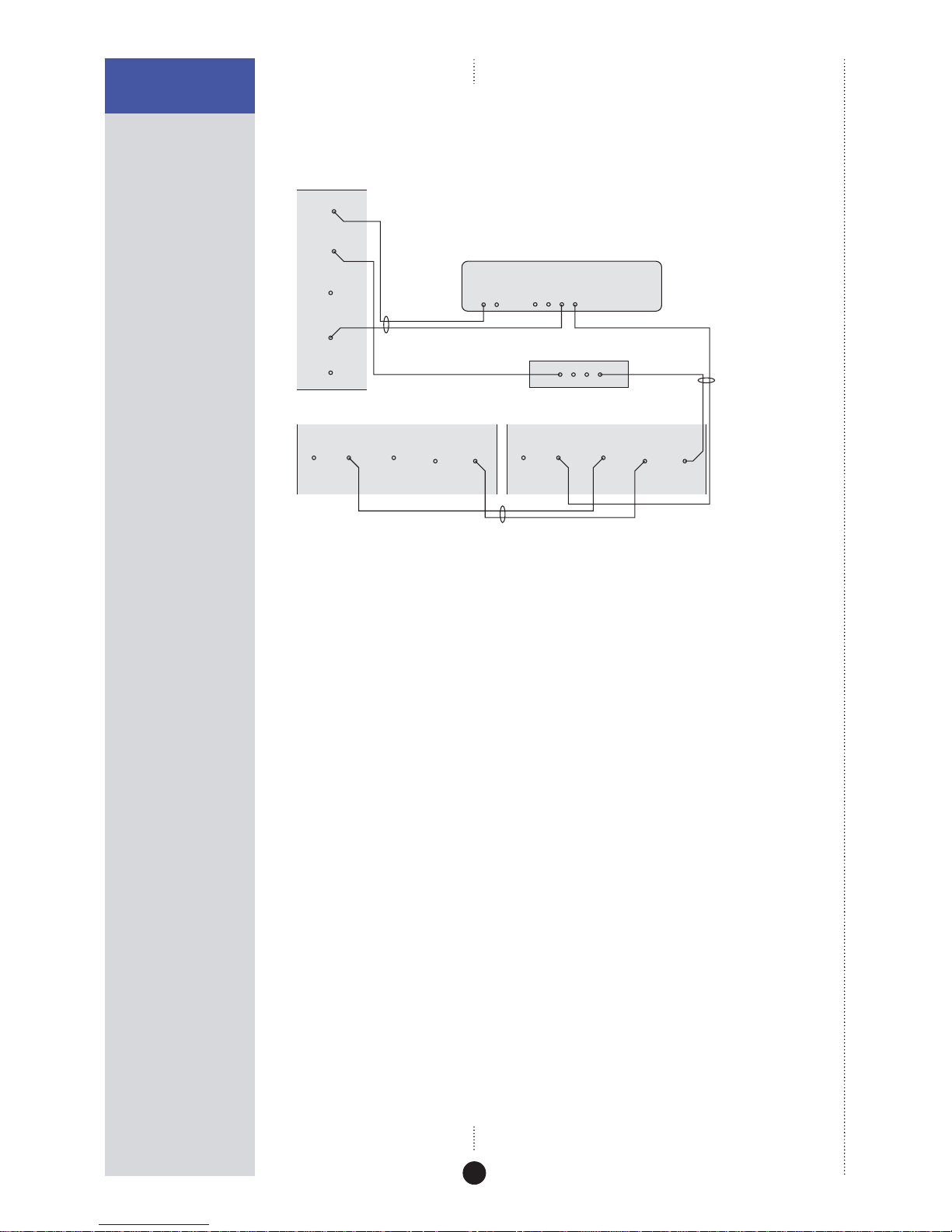
To connect three or more DSP loudspeakers in a
Meridian surround system
COMMS
OUTPUT INPUT
DIGITAL INPUT
21
DIGITAL
OUTPUT
COMMS
OUTPUT INPUT
DIGITAL INPUT
21
DIGITAL
OUTPUT
COMMS
OUTPUT INPUT
DIGITAL INPUT
21
DIGITAL
OUTPUT
DSP loudspeaker
Centre (master)
DIGITAL OUTPUTSCOMMS
S5 lead
M5 lead
S5 lead (digital unused)
Meridian Surround Processor
511 S-patch box
S5 lead
DSP loudspeaker – Main R DSP loudspeaker – Main L
If your system includes more than two Meridian DSP loudspeakers you will
need a 511 S-patch box (available separately) to link together the S5 leads
from each speaker, as shown above. Note: This does not apply to the 861,
which includes a built-in patch box.
• Use the comms part of an M5 lead to connect one of the COMMS
sockets on the Meridian Surround Processor to the DSP loudspeaker you
have chosen as the master (typically the centre speaker).
• Use the audio part of the M5 lead to connect the DSP loudspeaker to
the appropriate digital output on the Meridian Surround Processor.
• Connect the COMMS output from the master DSP loudspeaker to one
socket on the 511 using an S5 lead.
• Link all the other DSP loudspeakers together in pairs using S5 leads, as
shown in the illustration.
• Connect each pair of DSP loudspeakers to the appropriate digital output
on the Meridian Surround Processor, using an S5 lead. The other part of
the S5 lead is used to distribute the COMMS from the 511 to each pair of
DSP loudspeakers.
Page 27
22
SETTING UP THE DSP
LOUDSPEAKERS
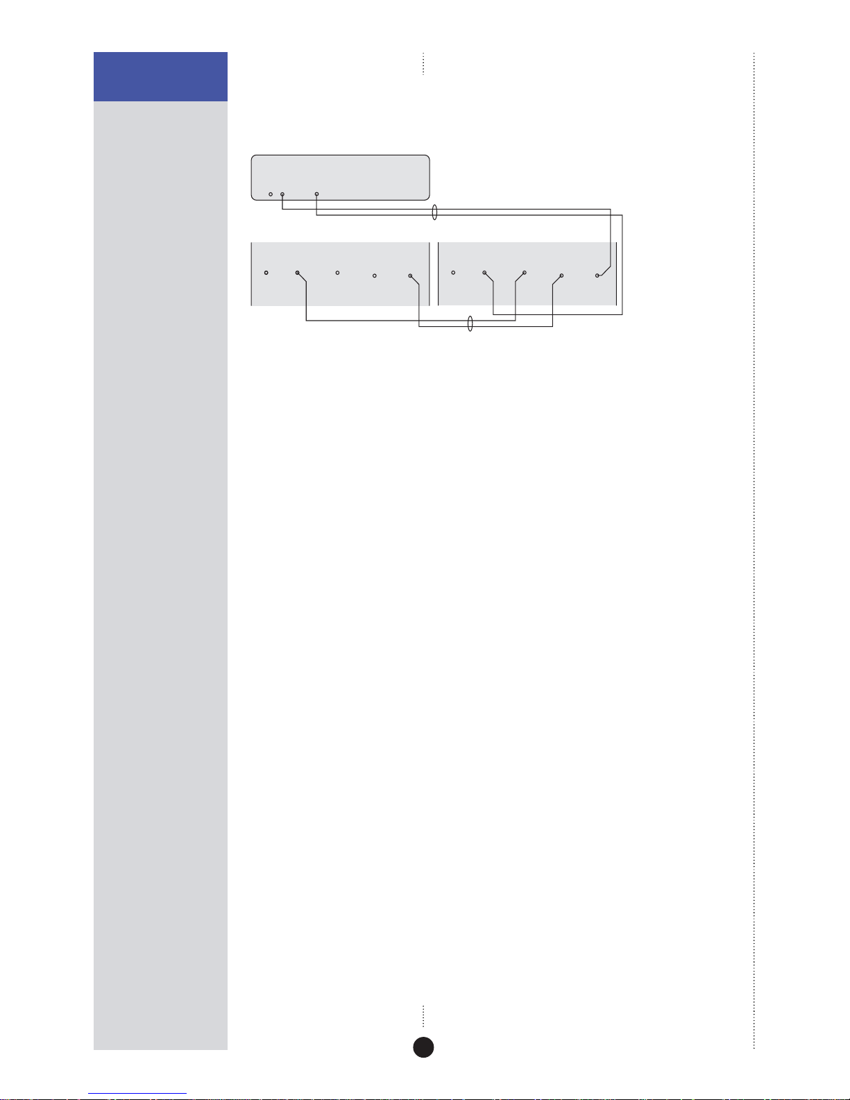
To connect two DSP loudspeakers to a Meridian CD
Player or other digital source
COMMS
OUTPUT INPUT
DIGITAL INPUT
21
DIGITAL
OUTPUT
DIGITAL
OUTPUT
COMMS
DSP loudspeaker – Main R DSP loudspeaker – Main L
M5 lead
588 CD Player
COMMS
OUTPUT INPUT
DIGITAL INPUT
21
DIGITAL
OUTPUT
S5 lead
You can create a complete system by connecting a pair of DSP loudspeakers
directly to a digital source. The DSP loudspeakers include volume, balance,
and tone controls allowing you to control the system using the Meridian
System Remote.
• Connect one of the COMMS sockets on the Meridian source, and the
digital output, to one of the DSP loudspeakers using the M5 lead.
• Link the two DSP loudspeakers together using the S5 lead, as shown in
the illustration.
You can connect another digital source to DIGITAL INPUT 2, and then
configure the appropriate source selection key on the remote to select that
input: see Configuring the sources, page 33.
See the chapter Using the DSP loudspeakers, page 23, for information
about controlling the DSP loudspeakers.
Page 28

23
Subtitle
Off
EnterReturn
Function 0Title
Chapter
Record
Slow
OSD
T
Angle Audio A-B Phase
Setup
Band
789
456
123
Menu Volume
Display
Mute
Preset
Clear
Store
Repeat
CD RADIO LP TV TAPE 1 TAPE 2 CDR CABLE
DVD
VCR 1 VCR 2 LD
Using the DSP loudspeakers
In systems with a Meridian preamplifier or control unit all of the
functions of the DSP loudspeakers, including volume, treble, and bass,
are operated via the controller. For more information refer to the user
guide for the preamplifier or control unit, and you can ignore this
chapter.
However, the DSP loudspeakers can also be connected directly to up to
two digital sources to create a complete, minimum system. This
chapter provides step-by-step instructions for operating the DSP
loudspeakers in a system with no Meridian preamplifier or control
unit.
Page 29
24
USING THE DSP
LOUDSPEAKERS
Selecting a source
When not playing, the DSP loudspeakers should be left in the standby
state. This uses a negligible amount of electricity, but ensures that the
components of the loudspeakers operate at maximum efficiency from the
moment you start.
If you are not going to use the DSP loudspeakers for several days you
should switch each unit completely off at the back panel, and disconnect it
from the AC power supply.
To select a source
• Press the appropriate source key on the remote; eg Radio.
This will bring the DSP loudspeakers out of standby, and the displays will
show the currently selected source and volume setting.
For example:
Radio 65
By default the 12 sources are available.
As standard, all the sources are set to select the D1 digital input. To select
the D2 input, see To configure a source, page 33.
To switch to standby
• Press Off on the remote.
The loudspeakers will switch to standby
and the displays will show:
.
Page 30

25
USING THE DSP
LOUDSPEAKERS
Changing the display
The DSP loudspeakers display information about the current settings on the
8-character front-panel display.
In addition, three coloured indicators show status information.
To change the displayed information
• Press Display.
Pressing Display steps between the following options:
Display option Example
Source and volume
Radio 65
Meridian source display
(dashes if not present)
----
Audio format
PCM 96k
Blank
The audio format display shows PCM, Data, or MHR followed by the
frequency, or NL (not locked).
Status indicators
The display includes the following status indicators:
Indicator Description
Red Master loudspeaker.
Yellow 88kHz or 96kHz input.
Green Clipping; see Troubleshooting, page 38.
.
Page 31

26
USING THE DSP
LOUDSPEAKERS
Adjusting the volume
The DSP loudspeakers adjust the volume in precise steps of 1dB, where 9dB
is equivalent to doubling the loudness, and can be varied in the range 1 to
99dB.
When you first connect power to the DSP loudspeakers the volume is set to
65, which is similar to the midway position of the rotary volume control on
a conventional preamplifier.
To change the volume
• Press the red A or V keys on the remote.
As you adjust the volume setting the display will show the current volume
level.
For example:
Radio 55
To mute (attenuate) the sound
• Press Mute on the remote.
The display will show:
Muted
.
To restore the sound
• Press Mute again on the remote.
Page 32
27
USING THE DSP
LOUDSPEAKERS
Changing the treble, bass, or phase
The DSP loudspeakers provide sophisticated treble and bass controls, to
allow you to adjust the broad balance of the system to correct for the
acoustics of your listening room, or for a misbalanced recording.
The controls are more subtle than conventional tone
controls, and take advantage of digital signal processing
techniques to provide a more natural adjustment of the
frequency response.
You can also change the absolute phase of the signal, to compensate for
signals which are out of phase, giving an unnatural-sounding bass.
To change the treble
• Press Function < or Function > until the display shows the current
treble.
For example:
Tre.+0.0
• Press Function A or Function V to change the treble.
The treble control tilts the frequency of the response over the entire
frequency range to make the sound brighter or dimmer. It can be adjusted
between ±10db in 0.5dB steps. Normally settings between +1.0 and -2.0 will
give the most natural results.
To change the bass
• Press Function < or Function > until the display shows the current bass
setting.
For example:
Bass+0.0
• Press Function A or Function V to change the bass.
The bass control allows you to adjust the bass response in the room by
±5dB in 0.5dB steps. Normally settings between +3.0 and -2.0 will give the
most natural results.
To change the absolute phase
• Press Function > or Function < until the display shows the current phase.
For example:
Phase +
• Press Function A or Function V to change the phase.
If you have a
Meridian Surround Controller
these functions are performed
via the sound controller.
Page 33
28
USING THE DSP
LOUDSPEAKERS
Changing the listening position
The balance control of the DSP loudspeakers uses digital signal
processing to compensate for an off-centre listening position
by delaying and diminishing the sound in one speaker, thus
effectively shifting the speaker’s image back.
The axis control allows you to adjust the optimum listening
height of the DSP loudspeakers, like a balance control
operating in the vertical plane.
To change the balance
• Press Function < or Function > on the remote until the display shows
the current balance.
For example:
Bal. <0>
• Press Function A or Function V to change the balance.
The display shows the direction and position of the listening position.
For example:
Bal. 12>
There are 32 steps in each direction.
To change the axis
• Press Function < or Function > on the remote until the display shows
the current axis setting.
For example:
Axis -1
• Press Function A or Function V to change the axis.
The axis can be adjusted between 3 and -2, where 0 corresponds to the axis
of the treble unit. Usually a listener will be below that position, so we
recommend settings of -1 or -2.
If you have a
Meridian Surround Controller
these functions are performed
via the sound controller.
Page 34

29
Subtitle
Off
EnterReturn
Function 0Title
Chapter
Record
Slow
OSD
T
Angle Audio A-B Phase
Setup
Band
789
456
123
Menu Volume
Display
Mute
Preset
Clear
Store
Repeat
CD RADIO LP TV TAPE 1 TAPE 2 CDR CABLE
DVD
VCR 1 VCR 2 LD
Configuring the DSP loudspeakers
This chapter explains how to configure the DSP loudspeakers to suit
the other equipment in your system.
The first stage in configuring the DSP loudspeakers is to choose one of
the standard settings, and these are designed to set all of the
parameters to their most common values.
You can also configure each setting individually for applications not
catered for by one of the standard settings.
Once you have configured the DSP loudspeakers you will probably
never need to change the configuration, unless you alter the
equipment connected to your system at a later stage.
Page 35
30
CONFIGURING THE
DSP LOUDSPEAKERS
Choosing standard settings
The DSP loudspeakers provide the following five alternative standard
settings, called Types, which configure all aspects of the DSP loudspeakers
into the most commonly needed configurations:
Type Description
1 For use with a Meridian control unit such as the 562V.2.
5 For use with a CD player connected to D1; all other sources use D2.
6 For use with a Meridian Surround Controller.
7 For use in a second room.
8 For use in the second or third room of a three-room system.
Types 2, 3, and 4 are for compatibility with 200/600 series units.
In all cases except Type 5, the D1 input is used for all sources.
Choosing one of the standard settings overrides any other configuration
you may have performed, and so can be used to reset the configuration of
the speakers.
To select a standard setting
• Switch off the DSP loudspeaker.
• Turn on the power again while holding down the key on the remote
corresponding to the Type you want to use.
The display will show the Type number.
For example:
Type 1
• Release the remote key.
The display will show:
L.
You should now specify the speaker’s position as follows.
Page 36

31
CONFIGURING THE
DSP LOUDSPEAKERS
To specify the speaker position
• Press A or V to specify the speaker position.
The options are shown in the following table:
Display Position
L. Left.
R. Right.
C. Centre (Type 6 only).
S.L. Left surround (Type 6 only).
S.R. Right surround (Type 6 only).
To choose master or slave
You should select one loudspeaker to be the master; this will normally be
the centre channel. For more information see Setting up the DSP
loudspeakers, page 13.
The other DSP loudspeakers should be configured as slaves as follows.
• Press the green > (Play) key on the remote.
The display shows, for example:
L. Slv.
When you have configured the loudspeaker:
• Switch off the DSP loudspeaker, using the power switch on the back,
and then switch on again to restore normal operation.
Page 37
32
CONFIGURING THE
DSP LOUDSPEAKERS
Specifying information about your
system
You can configure the operation of the DSP loudspeakers to suit the way
your system is set up, and the way in which you want to use it.
These settings are configured automatically to appropriate values when
you choose one of the standard Type settings, and you should not normally
need to alter them; see Choosing standard settings, page 30.
To configure the DSP loudspeaker
• Turn off the DSP loudspeaker, using the power switch on the back
panel.
• Turn on the power again while holding down the 0 key on the remote.
The display will show the current setting of the first configuration option.
For example
L.
• Press > or < to step between the options.
• Press A or V to change the value of the current option.
The table below shows the options you can configure:
Option Initial Value in Type 1
Position and master/slave
L.
Communications mode (500 or 200)
500
Controller mode (Auto, Con, or NCon)
Auto
System address (1–8)
S.A. 1
Product address (1–8)
P.A. 1
Volume mode (1=normal,
2/3=second/additional room)
L.E. 1
Balance control? (N or Y)
Bal. Y
Centre menus? (N or Y)
Centre N
Diagnostic displays? (N or Y)
Diag. N
Page 38

33
CONFIGURING THE
DSP LOUDSPEAKERS
Configuring the sources
When the master DSP loudspeaker is set to one of the standard Types the
12 source selection keys on the remote select inputs D1 and D2 as shown in
the table on page 34.
If the configuration you want is not catered for by one of the standard
settings, you can configure each source individually.
The DSP loudspeakers provide 12 sources corresponding to the 12 source
selection keys on the remote:
CD, Radio, LP, TV, Tape1, Tape2, CDR, Cable, DVD, VCR1, VCR2, and
LD.
For each source you can configure:
•
The label used for it on the front panel display, from a range of
alternative labels.
•
The digital input it selects.
•
The comms type and address, to control other Meridian 500 Series
equipment.
•
Other advanced options.
You only need to configure the sources on the DSP loudspeaker you have
specified as the master.
To configure a source
While in configuration mode:
• Press the source key on the remote corresponding to the source you
want to configure.
For example, to configure the Radio
source the display initially shows:
RD Radio
• Press > or < to step between options.
The right-hand set of characters shows the current value of the option.
• Press A or V to change the value of the option.
When you have finished programming sources:
• Switch off at the back panel, and then switch on again to restore normal
operation.
Page 39

34
CONFIGURING THE
DSP LOUDSPEAKERS
The options are summarised in the table below:
Option Initial value Alternatives Explanation
Label CD, Radio, LP, The label used to identify the
Radio
etc. source on the front panel display.
Audio input D1 or D2. Choose D1 or D2 to specify the
D1
input.
Comms type 1C – 9C, or NC. Choose 1C for a Meridian CD
2C
player, 2C for a Meridian FM
Tuner, 3C for a Meridian DVD
player, or NC otherwise.
Address 1A – 8A. Allows you to have up to eight of
1A
each source type.
FIFO Y or N. Choose N to disable the FIFO
FF. Y
buffer if you have difficulty
locking to a poor source.
Page 40
35
CONFIGURING THE
DSP LOUDSPEAKERS
Configuring the setup options
The setup options allow you to adjust the frequency response
of the loudspeakers to compensate for their position.
You only need to configure the master loudspeaker.
To select Setup mode
• Turn off the DSP loudspeaker using the power switch on the back panel.
• Turn on the power again while holding down the Store key on the
remote.
The display will show:
Setup
It will then revert to standby:
.
You can now operate the speaker in the usual way, using the additional
setup menus to adjust the response while listening to sources.
When you have finished adjusting the setup options:
• Switch off at the back panel, and then switch on again to restore normal
operation with the setup you have programmed.
To adjust the frequency response
• Press Function > or Function < until the display shows the current
response setting.
For example:
Free
• Press Function A or Function V to select the appropriate option as
follows:
Option What it means
Flat frequency response
Free
Speaker closer than 0.5m (20") to a wall.
Boundary
Applies a second-order high-pass filter at
Sub.1
80Hz for use with an analogue subwoofer.
Applies a second-order high-pass filter at
Sub.2
120Hz for use with an analogue subwoofer.
Speaker closer than 0.5m (20") to a corner.
Corner
When configuring the DSP
loudspeakers, point the remote at
the speakers, even if you have a
Meridian Surround Controller.
Page 41
36
CONFIGURING THE
DSP LOUDSPEAKERS
To adjust the centre frequency response and tilt offset
If your system includes a DSP centre speaker you should set Centre Y on
the master speaker. An additional frequency response option is then
provided to allow you to adjust the centre speaker, with the options:
C.Fre, C.bou, C.Sb1, C.Sb2, and C.Cor.
• Press Function > or Function < until the display shows the current
centre frequency response.
For example:
C.Fre
• Press Function A or Function V to select the appropriate option for
the centre speaker.
An additional centre tilt offset option is also provided. The centre tilt offset
is added to the treble value for the selected source. The recommended
setting is -1dB when the speaker is positioned above a television.
• Press Function > or Function < until the display shows the current
centre tilt offset.
For example:
C.Tilt+1
• Press Function A or Function V to adjust the centre tilt offset.
To store the settings
Once you have adjusted the frequency response for the speakers in your
system you should store the settings using the following procedure:
• Press Function Store.
The display shows:
Store
• Turn off the DSP loudspeaker using the power switch on the back panel.
When you turn on the power again the speaker will operate normally with
the frequency response settings you have stored.
Page 42

37
Subtitle
Off
EnterReturn
Function 0Title
Chapter
Record
Slow
OSD
T
Angle Audio A-B Phase
Setup
Band
789
456
123
Menu Volume
Display
Mute
Preset
Clear
Store
Repeat
CD RADIO LP TV TAPE 1 TAPE 2 CDR CABLE
DVD
VCR 1 VCR 2 LD
Troubleshooting
This chapter provides suggested solutions to typical problems that
may occur when setting up the DSP loudspeakers.
If you are still not able to resolve a difficulty with the help of this
guide and the suggestions in the following pages, please contact your
Meridian dealer or Meridian Audio Ltd.
Page 43

38
TROUBLESHOOTING
Troubleshooting
Display on front panel not lit
Check the following:
•
There is AC power connected to the socket on the back of the DSP
loudspeaker.
•
The power switch on the back panel of the DSP loudspeaker is turned
on.
If the display will still not illuminate, check any fuses in your power supply
and the fuse in the inlet of the DSP loudspeaker. If these are all intact,
contact your dealer.
Remote not working
Check the following:
•
The battery in the Meridian System Remote.
•
See if the DSP loudspeaker has been set up as not controller in the
Meridian Configuration program; see Changing the setup options, page
35. Note: This may be deliberate by your dealer.
Unit goes silent when played hard and displays ‘Hot‘
•
The DSP loudspeakers have a temperature sensing system on board,
which prevents overheating of the electronics. The sound will continue
when the speaker has cooled.
There is radio interference
The DSP loudspeaker is a digital audio and computing device which has
been designed to very high standards of electromagnetic compatibility.
If this equipment does cause or suffer from interference to/from radio or
television reception then the following measures should be tried:
•
Reorient the receiving aerial (or antenna) or route the antenna cable of
the receiver as far as possible from the DSP loudspeaker and its cabling.
•
Ensure that the receiver uses well-screened antenna cable.
•
Relocate the receiver with respect to the DSP loudspeaker.
•
Connect the receiver and this product to different AC outlets.
•
If the problem persists contact your dealer.
Page 44

39
TROUBLESHOOTING
Drive units move when the speaker is switched on or
off
This is normal as the speaker active electronics settle.
Configuring the DSP loudspeaker does not have any
effect
Make sure that you are configuring the DSP loudspeaker used as the
master digital loudspeaker in the system. This determines the configuration
of all digital loudspeakers in the system.
Unit stays in standby
•
Check that it is connected correctly.
•
Turn the system on from another Meridian product in the system.
Only the master loudspeaker plays
•
Check the S5 cables are connected correctly.
Sound is odd or mono
•
Check that the DSP loudspeakers are correctly configured as Left and
Right respectively.
Page 45

40
TROUBLESHOOTING
Cleaning
Cleaning (DSP6000 and DSP6000C only)
Small marks on the lacquer surface can usually be removed by treating with
Black Turtle Wax Color Magic.
Do not use any coarse polish such as Auto Colour restorer, and always test
any polish on a non-visible area first. Do not use any polish containing a
solvent; these can cause crazing of the surface.
Deeper scratches can be removed by treating with additional polyester
lacquer filler and then polishing carefully. Consult your authorised
Meridian dealer for advice before attempting any repair.
Page 46

41
TROUBLESHOOTING
Service and guarantee
Service
The Meridian components have been carefully designed to give years of
untroubled service. There are no user-serviceable parts inside the case, nor
do the units require any form of maintenance.
In the unlikely event that your DSP loudspeaker fails to function correctly,
it should be returned, in its original packaging, to your Meridian dealer.
In case of difficulty within the UK or USA please contact the appropriate
sales and service address shown on page ii.
In case of difficulty outside the UK or USA, contact the importing agent for
the territory. A list of Meridian agents abroad is available from Meridian
Audio.
No responsibility can be accepted for the DSP loudspeakers whilst in transit
to the factory or an agent, and customers are therefore advised to insure
the unit. When seeking service under guarantee, proof of the date of
purchase will be required.
Guarantee
Each DSP Digital Loudspeaker System is guaranteed against defects in
material and workmanship for two years from the date of purchase.
The guarantee is void if the DSP Digital Loudspeaker System has been
subject to misuse, accident, or negligence, or has been tampered with or
modified in any way without the written authorisation of Meridian Audio
Limited. Note that connecting anything other than the correct network
lead to the COMMS sockets may cause damage to the DSP Digital
Loudspeaker System which will not be covered by this guarantee.
Attempted servicing by unauthorised people may also invalidate this
guarantee. Labour and carriage charges are not covered unless by local
agreement.
Outside the UK, local warranty liability is restricted to equipment
purchased within the territory. Our agents abroad are only under
contractual obligation to service under guarantee equipment sold through
them. They are entitled to make a non-refundable charge for any service
carried out on other equipment.
This guarantee does not limit your statutory rights within the United
Kingdom.
Page 47

42
TROUBLESHOOTING
Page 48

43
Index
A
absolute phase, changing 27
accessories 12
axis, changing 28
B
back panel 19
balance, changing 28
bass, changing 27
bumpons, fitting 16
C
cabinet 3
centre frequency response,
configuring 36
centre speaker, connecting 20
centre tilt offset, configuring 36
cleaning 40
COMMS INPUT 19
COMMS OUTPUT 19
communications connections 19
components 14
configuration options 32
balance control 32
centre menus 32
communications mode 32
controller mode 32
diagnostic displays 32
position and master/slave 32
product address 32
system address 32
volume mode 32
configuring setup options 35
configuring sources 33
address 34
audio input 34
comms type 34
FIFO 34
label 34
connecting the loudspeakers 19
connecting to other equipment 20
connections
COMMS INPUT 19
COMMS OUTPUT 19
communications 19
digital inputs 19
digital output 19
RS232 19
D
digital inputs 19
digital output 19
dismantling the loudspeakers 16
display, changing 25
drive units 2, 15
F
feet, fitting 15
frequency response, configuring 35
G
grilles, removing (DSP5500) 15
guarantee 41
H
head units, installing 16
L
lacquer finish 15
polishing 40
listening position, changing 28
M
master, selecting 31
Meridian comms 4
Meridian Digital Music System 5
Meridian Digital Theatre™ 5
Meridian High Resolution (MHR) 3
mounting options 3
muting the sound 26
P
phase, changing 27
positioning the loudspeakers 18
power amplifiers 3
Page 49

44
R
radio interference 17, 38
remote, troubleshooting 38
S
safety warnings 18
sample configurations
Meridian Digital Music System 5
Meridian Digital Theatre™ 5
selecting a source 24
service 41
settings, storing 36
setup options, configuring 35
sources
configuring 33
selecting 24
speaker positioning 18
specification
DSP5000 and DSP5000C 6
DSP5500, DSP5500HC, and DSP5500C 8
DSP6000 and DSP6000C 10
standard settings, selecting 30
standby, switching to 24
status indicators 25
storing settings 36
switching to standby 24
T
tightening the drive units 15
tilt offset, configuring 36
treble, changing 27
troubleshooting 37
U
unpacking 14
V
volume
adjusting 26
muting 26
 Loading...