

Meridian C61R Installation Manual

C61R Digital Surround Controller
Installation Guide
P r e f a c e
i i
Important safety instructions
• Read the instructions.
• Keep these instructions.
• Follow all instructions.
• Do not use this apparatus near water.
• Clean only with a dry cloth.
• Install only in accordance with the manufacturer’s instructions.
• Refer all servicing to approved service personnel.
WARNING: TO REDUCE THE RISK OF FIRE OR ELECTRIC SHOCK,
DO NOT EXPOSE THIS APPARATUS TO RAIN OR MOISTURE.
This apparatus has been designed with Class 1 construction and
must be connected to a mains socket outlet with a protective
earthing connection (the third grounding pin).
This apparatus uses a single-pole power switch. As a result it is
not isolated from AC mains power when switched off at the rear
panel. The apparatus may be isolated from mains power either by
unplugging the power connector from the rear of the unit, or by
unplugging the connector at the opposing end of the power cord
or cable from its supply outlet. As a result, either or both of these
connectors should remain accessible
Safety warnings
• Do not expose the product to dripping or splashing.
• Do not place any object filled with liquid, such as a vase, on the
product.
• Do not place naked flame sources, such as lighted candles, on the
product.
To avoid interference
Do not position the product:
• Near strong magnetic radiation, such as near a power amplifier.
• Near to a television, or where connecting cables may be subject
to or cause interference.
To avoid overheating
• Leave at least 10cm around the equipment to ensure sufficient
ventilation.
Do not position the product:
• In direct sunlight.
• Near heat sources, such as a radiator.
• Stacked with any other audio products, as the heat it generates
may damage the other products.
• On a soft surface, such as a carpet, which would obstruct the
ventilation holes in the base.
The product normally runs warm to the touch.
Radio interference
FCC Warning: This equipment generates and can radiate radio
frequency energy and if not installed and used correctly in
accordance with our instructions may cause interference to radio
communications or radio and television reception. It has been type-
tested and complies with the limits set out in Subpart J, Part 15 of
FCC rules for a Class B computing device. These limits are intended
to provide reasonable protection against such interference in home
installations.
EEC: This product has been designed and type-tested to comply
with the limits set out in EN55013 and EN55020.

C o n t e n t s
i i i
Contents
Introduction 1
Provides information about the C61R digital surround
controller, and technical specifications.
Specifications 3
Installing the digital surround controller 5
Describes how to install the digital surround controller and
connect it to the other equipment in the system.
Unpacking 5
Audio inputs 6
Audio outputs 10
Communications connections 14
Configuring the digital surround
controller 17
Explains how to configure the digital surround controller
using the front-panel controls.
Configuration Wizard 17
Stage 1: Resetting the product 18
Stage 2: Configuring speakers 20
Stage 3: Configuring sources 22
Stage 4: Configuring other settings 24
Calibrating the system 27
Describes how to fine-tune the digital surround controller
to achieve the optimum performance from your sources and
speaker layout.
Introduction 27
Calibration tests 29
Speaker size 31
Using the Sine/Sub/Sens controls 32
Meridian Configuration Program 35
Explains how to install the Meridian Configuration Program,
with a general overview of its key feature, and gives
complete step-by-step instructions for creating a complete
configuration for a typical simple system.
Overview 35
Installing and running the Meridian Configuration
Program 38
Quick tour 39
Products: Inserting a source 44
Products: Adding speakers 48
Soft keys 51
Bass management 53
Speaker distances 55
Speaker calibration 56
Room correction 58
DSP presets 59
Tuner presets 61
Store settings 62
Finish 63
Room Correction 65
Explains how to run the Meridian Room Correction program
and create profiles for use with the digital surround controller.
Introduction 65
Auto Build 67
Viewing and repeating measurements 70
Viewing profiles 74
Editing filters 75
Changing settings at a later date 78

C o n t e n t s
i v
Control Window 81
Explains how to control a Meridian product from a PC via a
serial or USB cable.
Running the Meridian Control Window 81
Emulating an MSR+ or MSR 82
Using the Command tab 83
DSP presets 85
Gives details of the DSP presets and their parameters, and
describes how to modify them.
DSP presets 85
Defining your own presets 95
Troubleshooting 97
Provides suggested solutions to problems while installing,
configuring, or operating the product.
Maintenance 103
Service and guarantee 104
Index 105

P r e f a c e
v
Copyright and acknowledgements
Sales and service in the UK
Meridian Audio Ltd
Latham Road
Huntingdon
Cambridgeshire
PE29 6YE
England
Tel +44 (0)1480 445678
Fax +44 (0)1480 445686
World Wide Web – http://www.meridian-audio.com/
Copyright © 2003-2007 Meridian Audio Ltd
Designed and manufactured in the UK by Meridian Audio
Ltd. Meridian Audio reserves the right to make changes and
improvements to any of the products described in this document
without prior notice.
Dolby, Dolby Digital, Pro Logic, AC-3, PLII, PLIIx, AAC, and the
double-D symbol are trademarks of Dolby Laboratories Licensing
Corporation. Lucasfilm, THX, and THX Cinema are registered
trademarks of Lucasfilm Ltd. Surround EX is a jointly developed
technology of THX and Dolby Laboratories, Inc and is a trademark
of Dolby Laboratories, Inc. All rights reserved. Used under
authorisation. DTS is a registered trademark of Digital Theatre
Systems Inc. MPEG is a registered trademark of the MPEG
organisation. Ambisonic is a registered trademark of Nimbus
Records Ltd. Trifield is a trademark of Trifield Productions Ltd.
LaserDisc is a trademark of Pioneer Electric Corp.
Boothroyd|Stuart Meridian, Meridian, and Meridian Digital Theatre
are registered trademarks of Meridian Audio Ltd.
Part no: C61R/1 (P80404)
Sales and service in the USA
Meridian America Inc
8055 Troon Circle
Suite C
Austell
GA30168-7849
USA
Tel +1 (404) 344 7111
Fax +1 (404) 346 7111
This guide was produced by Human-Computer Interface Ltd,
http://www.interface.co.uk/
Manufactured under license from Dolby Laboratories, Lucasfilm Ltd.
(US patents 5,043,970;5,189,703;5,222,059. European patent
0323830), Trifield Productions Ltd, and Nimbus Records Ltd.
MHR: This product incorporates patented copyright protection
technology and intellectual property of Meridian Audio Ltd.
This technology is provided for the express purpose of securely
containing copyright audio within the Meridian System only.
Reverse engineering or circumvention of this protection is strictly
prohibited.

P r e f a c e
v i

I n t r o d u c t i o n
1
Introduction
This guide provides full information about unpacking the C61R Digital Surround Controller,
connecting it to the other equipment in the system, and configuring it using the front panel.
Once you have connected and configured the product, refer to the
G Series System Guide
for
information about operating it.
The C61R is a powerful, flexible surround controller, with 8
unbalanced analogue outputs and 10 digital outputs.
At the heart of the C61R is a powerful DSP engine consisting
of three Motorola 56367s running at 150MHz – delivering an
incredible 450MIPS (million instructions per second) capability.
Processing is performed at high sample rates and with 48-bit
precision throughout, ensuring that all filtering, processing, and
other operations are carried out beyond the limits of human
hearing. The C61R is thus a perfect processor for the very latest in
digital audio, such as DVD-Audio and DVD-Video.
Inputs
Analogue signals are converted via a 24-bit Delta-Sigma converter
to high-sample-rate digital on input to the processor, while all
digital signals are reclocked to minimise jitter and maintain total
data integrity. The C61R includes two six-channel S/PDIF digital
inputs (coax), a USB audio input, four TOSlink optical inputs, and
six more stereo coax digital inputs. In addition, there is a six-
channel analogue input, and five stereo analogue inputs.
Formats supported
The C61R combines controller and surround processor functions,
meeting the latest THX specifications and including MPEG, DTS,
Dolby, Trifield, and Ambisonic decoding. In many cases the decoders
incorporate our own code, giving them superior integration with
the Meridian design philosophy, as well as superior performance.
As a result, the C61R can decode surround signals from all PCM
optical discs. The C61R is thus an ideal complement to a G Series
optical disc player like the G98.
Smart Source feature
The C61R’s ’Smart Source’ feature continually monitors the digital
inputs and automatically loads the correct decoding software for
the format, speaker layout, and encoding of the incoming signal.
This capability is enhanced by MHR SmartLink, which provides a
digital link between a Meridian optical disc player and processor,

I n t r o d u c t i o n
2
carrying explicit information about the nature of the datastream as
well as encrypted high-resolution digital signals from DVD-Audio
– the first system of its kind to be approved. Virtually all other
manufacturers oblige you to go through an analogue connection,
losing quality in the process.
You can also store separate parameters for each source (such
as DVD) depending on whether the incoming signal is stereo or
surround, so that any source material is played with the DSP mode
of your choice.
Meridian Room Correction
The C61R incorporates Meridian Room Correction, a unique system
that compensates for acoustic deficiencies in your listening room,
particularly at the bass end. It achieves this by automatically
analysing the room response and then using powerful Digital
Signal Processing (DSP) technology to build a set of filters, called a
profile. This audibly improves the sound by eliminating resonances
and making the decay time consistent for frequencies below about
250Hz.
I n t r o d u c t i o n
3
Specifications
Digital coax inputs 6 coax digital inputs, 2 6-channel coax inputs, all MHR.
USB input 1 USB digital input allows connection to a Windows PC or Macintosh.
Digital optical inputs 5 optical digital inputs.
Analogue inputs 8 stereo unbalanced inputs; A1-A3 and A4-A6 can be used as two 6-channel unbalanced inputs.
Digital outputs Main, Centre/Sub, Sides, Rears, A/B*.
Unbalanced analogue
outputs
Main L/R, Centre/Sub, Rears, LZ/RZ†.
Trigger outputs 3 12VDC/100mA trigger outputs configurable by source.
Comms 2 5-pin 240º DIN sockets, BNC socket, USB, RS232 interface.
Conversion Up to 192kHz, 24-bit Sigma-Delta conversion on all analogue inputs and outputs.
Formats Include Dolby Digital, DTS, MPEG Surround, and AAC.
DSP modes Direct, Music, Trifield, Ambisonics, Super, Stereo, MusicLogic, Mono, TV Logic, PLIIx Music, PLIIx Movie, PLIIx
THX, Discrete, Cinema, PLIIx Mov6, PLIIx Mus6, THX, THX Surround EX, THX Ultra2 Cinema, THX Music.
Power Universal supply 100-240V, 50-60Hz, 40W.
Processing 3 Motorola 56367s running at 150MHz to give a total of approximately 450MIPS. 48-bit arithmetic
throughout.
Dimensions 440mm x 90mm x 350mm (17.32" x 3.54" x 13.78") WHD.
Weight 8.5kg (18lb) approx.
Controls Front-panel soft keys include control of Source, Preset, etc. Standby and display buttons, volume control,
mute. Full remote control of all features via MSR+.
Display Multi-character dot-matrix Vacuum Fluorescent Display.
Indicators Standby button lit when off.
*A/B: Subs if two or three subs are used. Optional ceiling speakers with future software update.
†LZ/RZ: May be chosen to be any pair from: Main L/R, Centre/Sub, Sides, Rears, Subs.
Note: Current software supports a maximum of eight outputs. Future software may support up to 12.

I n t r o d u c t i o n
4

I ns t a l li n g t h e
d ig i t a l s ur r o u nd
c on t r o ll e r
5
Installing the digital surround controller
Unpacking
The C61R Digital Surround Controller is supplied with the following
accessories:
• MSR+ remote control with batteries, manual, and spare key caps.
• Meridian Comms lead.
• Power cord.
• This manual.
•
Meridian G Series System Guide.
If any of these items are missing please contact your dealer.
Note: You should retain the packaging in case you need to
transport the unit.
This chapter explains how to install the digital surround controller. It describes what you
should find when you unpack the product, and how you should connect it to the other
equipment in the system.
You should not make any connections to the product or to any other component in the
system while the AC power supply is connected and switched on.
I ns t a l li n g t h e
d ig i t a l s ur r o u nd
c on t r o ll e r
6
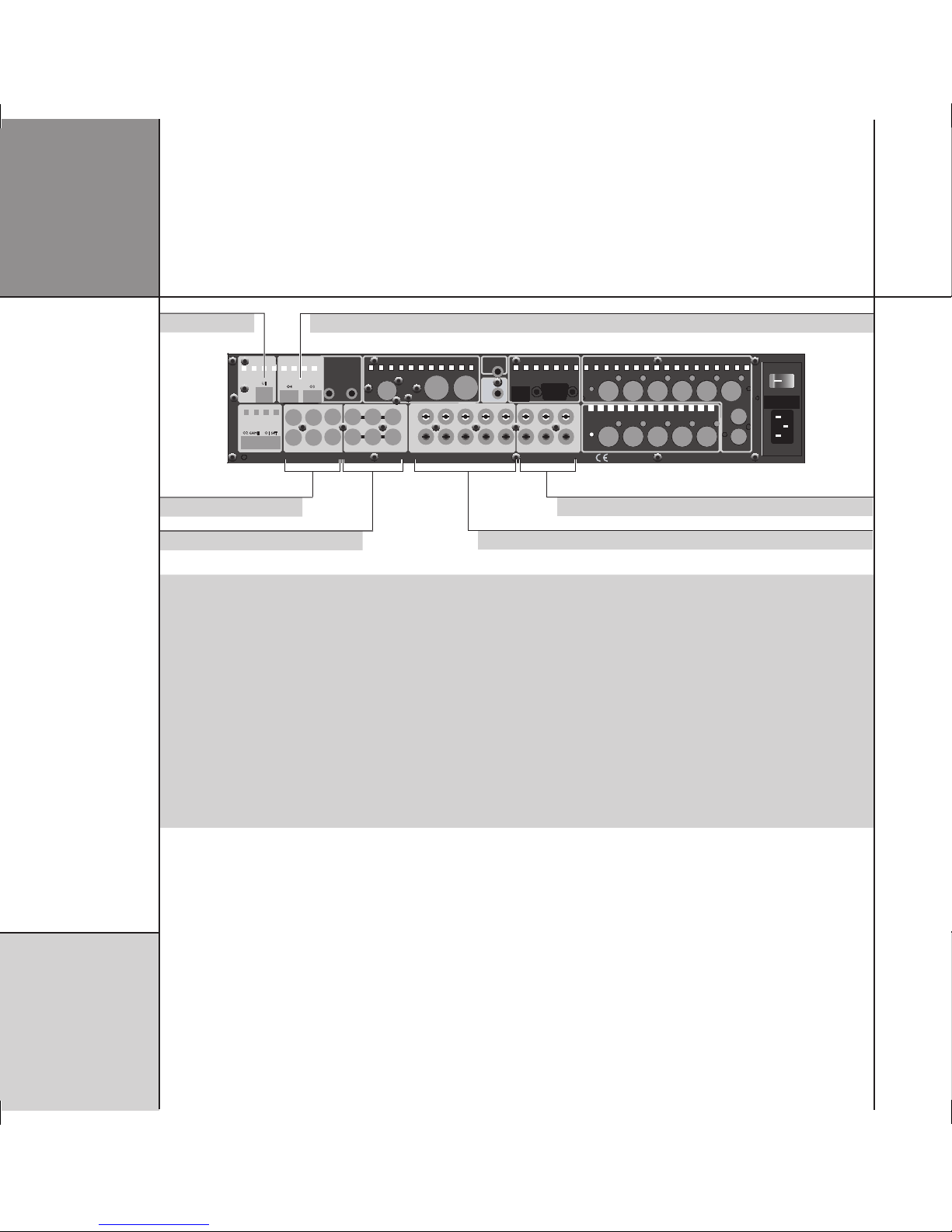
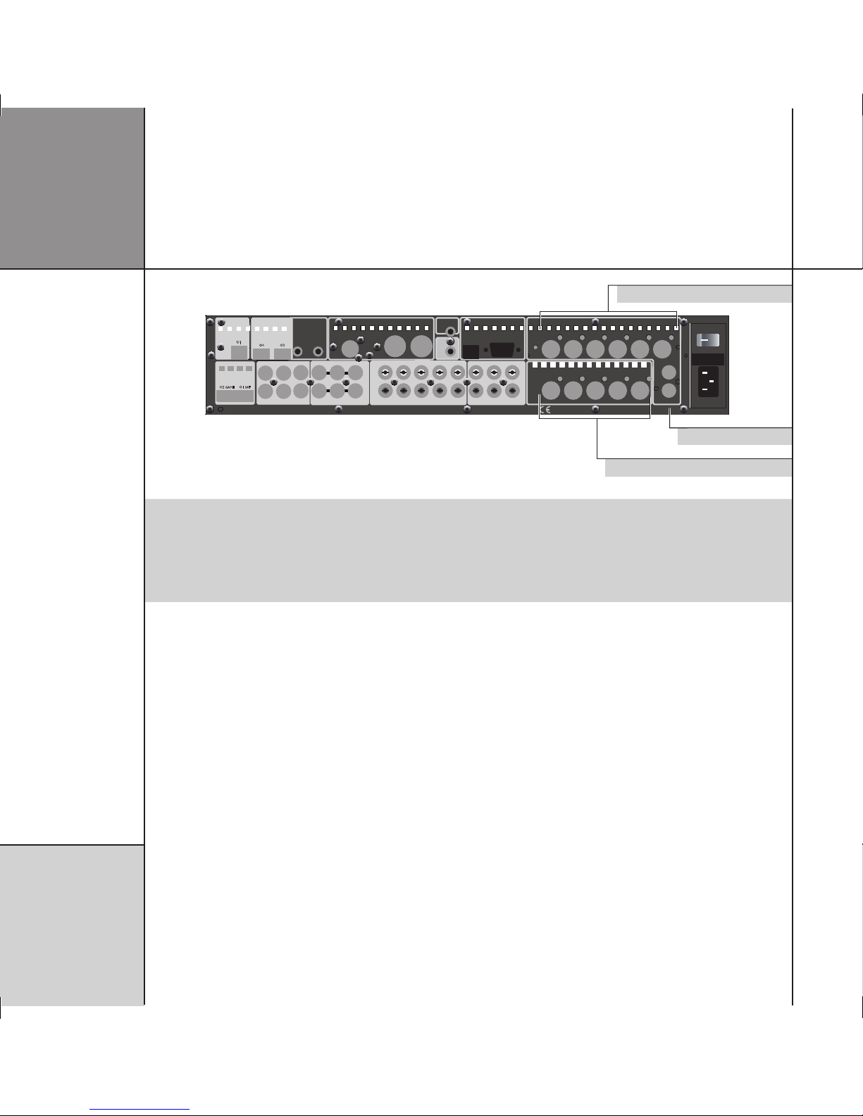
Audio inputs
MAIN L/R CENTRE/
SUB
SIDES
REARS A/B
DIGITAL OUTPUT
MAIN L REAR R CENTRE
SUB
MAIN R REAR L
LZ
RZ
ANALOGUE OUTPUT
MAINTENANCE
USB RS232
MERIDIAN COMMS
TRIGGER 1
+12V 100mA
IR IN
OPTICAL INPUT
D12 D10
D11 D9 VCR2
SURR C/LFE L/R
MULTI DIGITAL INPUT
MD1
MD2
DVD
DIGITAL IN
MULTI ANALOGUE INPUT
A8 A7 VCR1 A6 CABLE A5 TV A4 TAPE SURR R
MIC
LFE RIGHT
SURR L CENTRE LEFT
MA1
AUX
ANALOGUE INPUT
L
R
TRIGGERS
+12V 100mA
3 2
CAUTION REPLACE WITH SAME TYPE FUSE
T1.6AL 250V for 100 - 240V
POWER INPUT ~50-60Hz 40VA MAX
ON OFF
G61 SURROUND CONTROLLER DESIGNED AND MADE IN ENGLAND BY MERIDIAN AUDIO LTD DESIGN AND COPYRIGHT 2005
D11 D9 VCR2
D12 D10
DIGITAL INPUT
OPTICAL INPUT
OPTICAL INPUT
USB
AUDIO IN
O3O4
U1
O2 GAME O1 SAT
D8 DISC
D7 CD
Digital coax inputs
USB input
Multichannel analogue inputs
Multichannel digital coax inputs
Optical inputs
Analogue inputs
Use this connector To connect to this
MULTI DIGITAL INPUT 1 (DVD) or D1-D3,
MULTI DIGITAL INPUT 2 or D4-D6
The multichannel digital output of a source such as the G98DH DVD Audio Transport, or
three digital sources.
DIGITAL INPUT D7 (CD), D8 (DISC), D9
(VCR2), D10-D12
The digital output of a source such as a G07 24-bit CD Player or DAB tuner.
MULTI ANALOGUE INPUT 1 (AUX) or A1-A3 A multichannel analogue source such as an SACD player.
ANALOGUE INPUT A4 (TAPE), A5 (TV),
A6 (CABLE), A7 (VCR1) *
The unbalanced analogue output of a source such as a tape recorder, TV tuner, cable box,
or VCR.
USB INPUT U1 A computer USB port.
OPTICAL INPUT O2 (GAME), O3-O5 The optical output of a source such as a satellite receiver or computer game console.
ANALOGUE IN MIC (A8-L) An SPL meter for use in room correction configuration.
* A4-A6 can be used as MULTI ANALOGUE INPUT 2 to connect to a second multichannel analogue source such as an SACD player.
The default assignment of the sources to each input is shown in brackets after the input name in the above table. To assign a different
input to a source see
Configuring sources
, page 22.

I ns t a l li n g t h e
d ig i t a l s ur r o u nd
c on t r o ll e r
7
You can connect up to 12 digital coax sources to the C61R Digital
Surround Controller.
• Connect the digital source to one of the digital input sockets of
the digital surround controller, using a 75Ω screened coax phono
lead.
If the source is a Meridian product connect together the COMMS
sockets using the Comms lead provided.
To connect to a digital source (eg G06 24-bit CD Player)
C61R Digital Surround Controller
DIG IN
D7 CD
DIGITAL LEAD
COMMS LEAD
COMMS
DIGITAL OUT COMMS
G06 24-bit CD Player
To connect to an analogue source (eg TV tuner)
TV tuner
OUTPUT
PHONO LEADS
C61R Digital Surround Controller
ANALOGUE INPUT
A5 TV
You can connect up to eight analogue sources to the C61R Digital
Surround Controller.
• Connect the analogue source to one of the analogue input
sockets of the digital surround controller, using screened coax
phono leads.

I ns t a l li n g t h e
d ig i t a l s ur r o u nd
c on t r o ll e r
8
To connect to a DVD-Audio player with digital multichannel outputs (eg G98DH DVD Audio Transport)
G98DH DVD Audio Transport
3 x DIGITAL LEADS
COMMS LEAD
C61R Digital Surround Controller
MULTI
DIGITAL INPUT
(DVD)
COMMSCOMMS
MAIN DIGITAL OUT
The C61R Digital Surround Controller provides 12 digital coax
inputs, six of which can be used as two multichannel inputs from
a source with a suitable digital multichannel output, such as the
G98DH DVD Player.
• Connect the MAIN DIGITAL OUT on the G98DH to the MULTI
DIGITAL INPUT 1 on the C61R, using three 75Ω screened coax
phono leads.
• Connect together the COMMS sockets using the Comms lead
provided.
To connect to a computer via USB
Computer
USB
USB A-B CABLE
C61R Digital Surround Controller
USB INPUT
You can connect a Windows PC or Macintosh to the C61R via the
USB input to allow you to use the C61R as a digital audio output
device.
On a PC, Windows XP/SP2 or later is required. On a Macintosh,
OSX 10.4 or later is recommended. Linux computers that support
USB audio class drivers can also be used.
• Connect the computer’s USB port to USB INPUT U1 on the C61R
using a standard USB A-B cable. The flat rectangular end plugs
into the PC and the square end into the C61R.
The first time that the C61R is plugged in to the PC or Macintosh
it will automatically be recognised, and appropriate drivers will
be installed. The C61R will then appear as a sound output device
called Meridian 48k/16 in the Sound control panel (PC) or
Sound system preferences panel (Macintosh).
Note: The computer volume control will have no effect on the
playback volume; use the Meridian system control instead.
I ns t a l li n g t h e
d ig i t a l s ur r o u nd
c on t r o ll e r
9
To connect to a source with analogue multichannel outputs (eg SACD or DVD-A player)
SACD/DVD-A player
6 x PHONO LEADS
DIGITAL LEAD
C61R Digital Surround Controller
MULTI ANALOGUE
INPUT 1
MULTICHANNEL
OUTPUT
DIGITAL INPUT
D8 DISC
DIGITAL
OUTPUT
Analogue inputs A1 to A3 can be used as a multichannel input
from a source with a suitable analogue multichannel output, such
as an SACD player. Analogue inputs A4 to A6 can optionally be
used as a second multichannel analogue input.
• Connect the ANALOGUE OUTPUT sockets from the source to the
analogue multichannel inputs on the digital surround controller
using six phono leads.
• Optionally connect a digital output from the source to digital
input D8 (DISC) on the digital surround controller, using a digital
phono lead.
You can then select the source corresponding to the multichannel
input (AUX) for playing surround material, and the source
corresponding to the digital input (DISC) to decode other formats.
Note: Multichannel analogue sources may have subwoofer level
outputs that vary by up to 10dB, so it may be necessary to reduce
the LFE level to give correct bass integration; see
DSP presets
, page
85.
I ns t a l li n g t h e
d ig i t a l s ur r o u nd
c on t r o ll e r
1 0
Audio outputs
The C61R hardware architecture is designed to process up to 12
completely independent output channels. Currently the software
limits the number of outputs to a total of eight: Main L/R, Centre,
Sub, Rears, and either Sides or two more additional subwoofers.
The C61R provides analogue and/or digital output sockets for these
eight speakers.
MAIN L/R CENTRE/
SUB
SIDES
REARS A/B
MAIN L REAR R CENTRE
SUB
MAIN R REAR L
LZ
RZ
ANALOGUE OUTPUT
MAINTENANCE
USB RS232
MERIDIAN COMMS
TRIGGER 1
+12V 100mA
IR IN
SURR C/LFE L/R
MD1
MD2
DVD
A8 A7 VCR1 A6 CABLE A5 TV A4 TAPE SURR R
MIC
LFE RIGHT
SURR L CENTRE LEFT
MA1
AUX
L
R
TRIGGERS
+12V 100mA
O2 GAME
O1 SAT
3 2
CAUTION REPLACE WITH SAME TYPE FUSE
T1.6AL 250V for 100 - 240V
POWER INPUT ~50-60Hz 40VA MAX
ON OFF
G61 SURROUND CONTROLLER DESIGNED AND MADE IN ENGLAND BY MERIDIAN AUDIO LTD DESIGN AND COPYRIGHT 2005
DIGITAL OUTPUT
OPTICAL INPUT
MULTI DIGITAL INPUT
MULTI ANALOGUE INPUT
ANALOGUE INPUT
D11 D9 VCR2
D12 D10
DIGITAL INPUT
OPTICAL INPUT
OPTICAL INPUT
USB
AUDIO IN
O3O4
U1
O2 GAME O1 SAT
D8 DISC
D7 CD
Analogue outputs
Analogue outputs
Digital outputs
Use this output To connect to this
DIGITAL OUTPUT MAIN L/R, CENTRE/SUB,
SIDES, REARS, A/B
Digital loudspeakers, using digital coax cables.
ANALOGUE OUTPUT LEFT, RIGHT, REAR L,
REAR R, CENTRE, SUB, LZ, RZ
The unbalanced analogue input of a power amplifier or active loudspeakers, using
screened coax phono leads.
I ns t a l li n g t h e
d ig i t a l s ur r o u nd
c on t r o ll e r
1 1
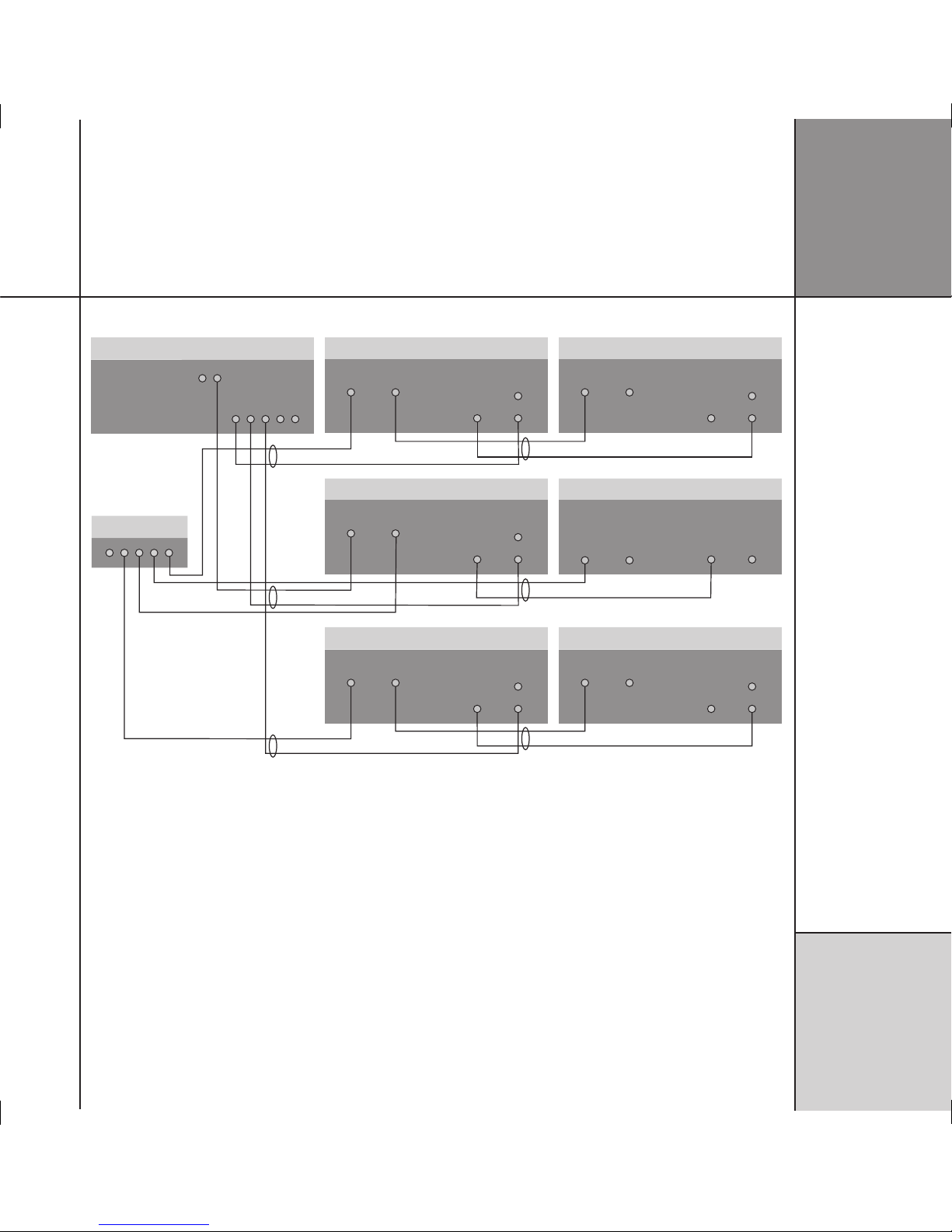
To connect the C61R to Meridian DSP loudspeakers
C61R Digital Surround Controller
DIGITAL OUTPUT
COMMS
511 S-patch box
S5 LEAD
(digital unused)
M5 LEAD
S5 LEAD
S5 LEAD
DSP5200 – Centre (Master)
COMMS
INPUT OUTPUT
DIGITAL
INPUTS
2
1
DIGITAL
OUTPUT
SW1600 – Sub (Slave)
COMMS
INPUT OUTPUT
DIGITAL
IN OUT
S5 LEAD
S5 LEAD
S5 LEAD
DSP5200 – Main Left (Slave)
COMMS
INPUT OUTPUT
DIGITAL
INPUTS
2
1
DIGITAL
OUTPUT
DSP5200 – Main Right (Slave)
COMMS
INPUT OUTPUT
DIGITAL
INPUTS
2
1
DIGITAL
OUTPUT
DSP5200 – Surr Left (Slave)
COMMS
INPUT OUTPUT
DIGITAL
INPUTS
2
1
DIGITAL
OUTPUT
DSP5200 – Surr Right (Slave)
COMMS
INPUT OUTPUT
DIGITAL
INPUTS
2
1
DIGITAL
OUTPUT
• Use the Comms part of an M5 lead to connect one of the
COMMS sockets on the C61R to the digital speaker you have
chosen as the master (typically the centre speaker).
• Use the audio part of the M5 lead to connect the digital speaker
to the appropriate digital output socket.
If the system includes more than two Meridian DSP loudspeakers
you may use a 511 S-patch box (available separately) to link
together the S5 leads from each speaker.
• Connect the COMMS output from the master digital speaker to
one socket on the 511 using an S5 lead.
• Link each pair of speakers together with an S5 lead, out of
the first speaker and into the second speaker, as shown in the
diagram.
• Connect the inputs to the first speaker of each additional pair
to the 511 (Comms) and the appropriate output of the C61R
(audio), using an S5 lead.
The speakers should then be configured appropriately as master
and slaves, and Left, Right, Centre, Surround; see
Meridian DSP
Loudspeaker User Guide
for more details.

I ns t a l li n g t h e
d ig i t a l s ur r o u nd
c on t r o ll e r
1 2
To connect the C61R to power amplifiers or to analogue active and passive speakers powered by a Meridian G41
CHANNEL 1 INPUTS
1 3 4
A B
2
CHANNEL 3
G41 Powered
Crossover/Amplifier
CHANNEL 2
CH. A CH. B
ANALOGUE OUT
C61R Digital Surround Controller
A330
Main right
A330
Centre
P330
Rear right
P330
Rear left
A330
Main left
Analogue subwoofer
COMMS
INPUT OUTPUT
PHONO
The C61R provides six analogue outputs to allow you to connect to
six power amplifiers and passive loudspeakers, or 300 Series Active
and Passive Installation Loudspeakers powered by the G41 Active
Crossover Amplifier.
• Connect the LEFT and RIGHT analogue outputs to the power
amplifier inputs for the main front loudspeakers.
• Connect the SURR L and SURR R analogue outputs to the power
amplifier inputs for the rear loudspeakers.
• Connect the CENTRE analogue output to the power amplifier
input for the centre loudspeaker.
• If the system includes a subwoofer connect the SUB analogue
output to an active analogue subwoofer, such as the Meridian
SW1600.
I ns t a l li n g t h e
d ig i t a l s ur r o u nd
c on t r o ll e r
1 3
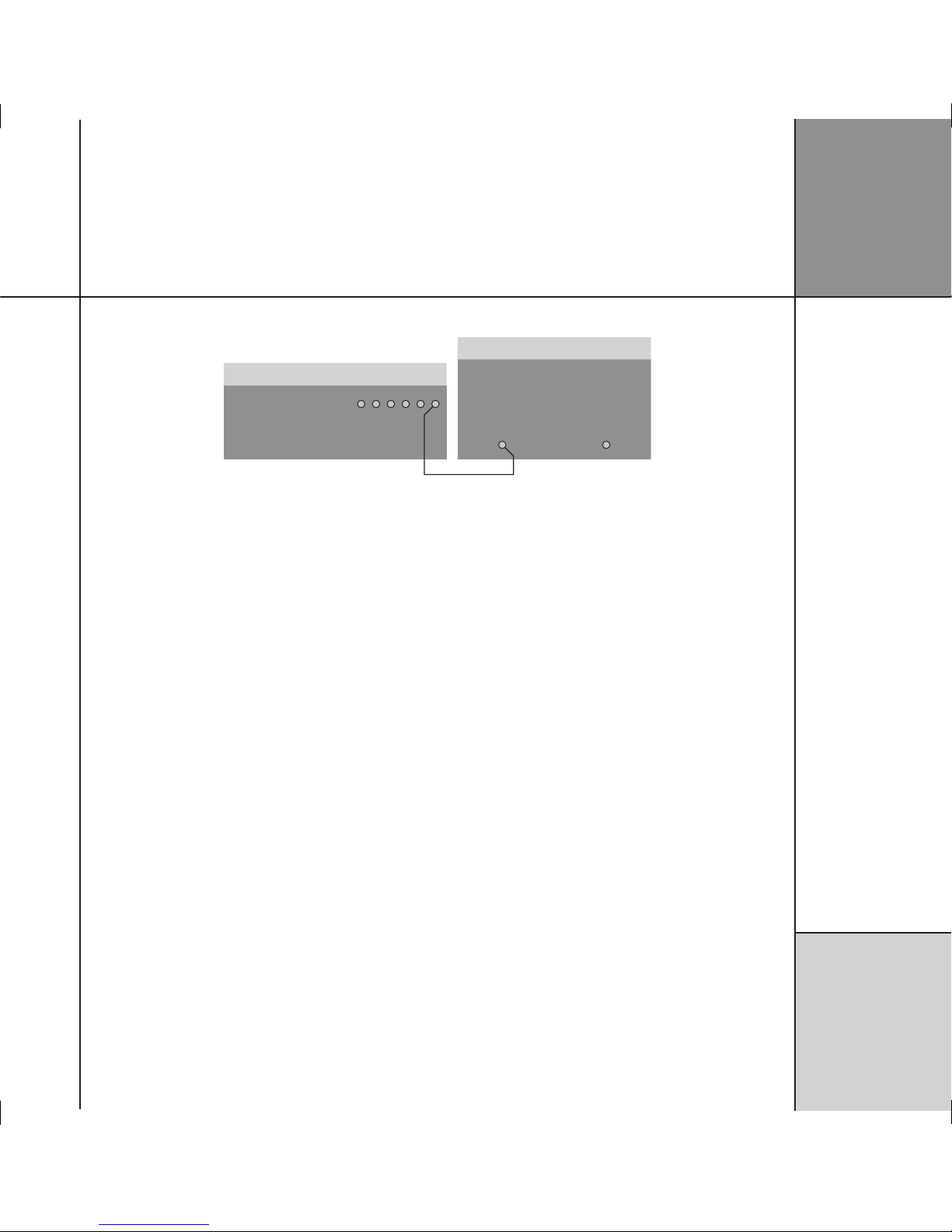
To connect to an active subwoofer (eg Meridian SW1600 or SW5500)
Subwoofer
PHONO LEAD
C61R Digital Surround Controller
SUB
CROSSOVER
INPUT
DIRECT
INPUT
The Meridian SW1600 and SW5500 subwoofers provide both
digital and analogue inputs, allowing you to connect them to
either the digital or analogue subwoofer outputs of the C61R. The
analogue connection must be used if you do not have a digital
main speaker.
• Connect the SUB analogue output socket from the C61R Digital
Surround Controller to the subwoofer’s line-level input using a
phono lead.
Use RZ and LZ if you have two subwoofers.
The digital surround controller provides a very high-quality
crossover for the subwoofer, and for best results you should use
this instead of the subwoofer’s crossover. To do this remove any
crossover in the subwoofer or set it to its highest setting (eg
200Hz). The subwoofer crossover can be set from the front panel of
the C61R; see
Subwoofer crossover frequency
, page 32.
I ns t a l li n g t h e
d ig i t a l s ur r o u nd
c on t r o ll e r
1 4
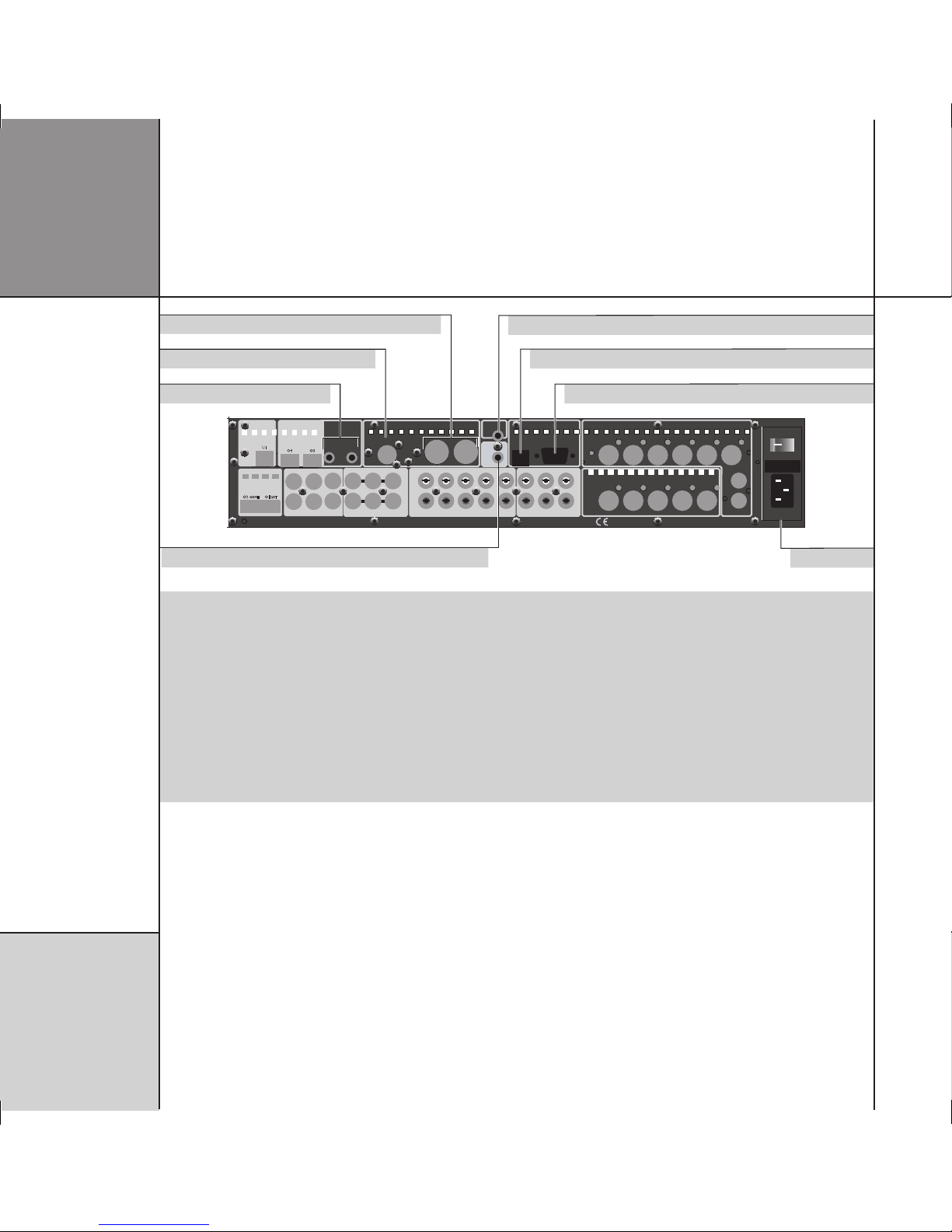
Communications connections
MAIN L/R CENTRE/
SUB
SIDES
REARS A/B
DIGITAL OUTPUT
MAIN L REAR R CENTRE
SUB
MAIN R REAR L
LZ
RZ
ANALOGUE OUTPUT
MAINTENANCE
USB RS232
MERIDIAN COMMS
TRIGGER 1
+12V 100mA
IR IN
SURR C/LFE L/R
MULTI DIGITAL INPUT
MD1
MD2
DVD
MULTI ANALOGUE INPUT
A8 A7 VCR1 A6 CABLE A5 TV A4 TAPE SURR R
MIC
LFE RIGHT
SURR L CENTRE LEFT
MA1
AUX
ANALOGUE INPUT
L
R
TRIGGERS
+12V 100mA
3 2
CAUTION REPLACE WITH SAME TYPE FUSE
T1.6AL 250V for 100 - 240V
POWER INPUT ~50-60Hz 40VA MAX
ON OFF
G61 SURROUND CONTROLLER DESIGNED AND MADE IN ENGLAND BY MERIDIAN AUDIO LTD DESIGN AND COPYRIGHT 2005
D11 D9 VCR2
D12 D10
DIGITAL INPUT
OPTICAL INPUT
OPTICAL INPUT
USB
AUDIO IN
O3O4
U1
O2 GAME O1 SAT
D8 DISC
D7 CD
Meridian BNC Comms
Meridian DIN Comms
Power & fuse
USB connection
Infra-red repeater input
Trigger output 1
RS232 connection
Trigger outputs 2 & 3
Use this connector To connect to this
DIN COMMS Other Meridian C Series, G Series, or 800 Series equipment, or Meridian DSP loudspeakers.
BNC COMMS Other Meridian C Series or G Series equipment, or some Meridian DSP loudspeakers.
RS232 connection* A computer, for configuring the digital surround controller.
USB connection A computer, for configuring the digital surround controller.
IR IN A G12 IR Receiver, or approved alternative infra-red repeater. Contact your dealer for details.
TRIG 1, TRIG 2, TRIG 3 Other equipment, via mono 3.5mm jack plug outputs (centre pin hot) providing 12VDC. They are always low
in standby. By default they are high for all sources, so can be used to bring a G Series power amplifier out of
standby. Alternatively you can program them to be high for specific sources; eg to control a projection screen.
*A second RS232 socket is provided on the front panel, and a switch allows you to select the active connector.
I ns t a l li n g t h e
d ig i t a l s ur r o u nd
c on t r o ll e r
1 5
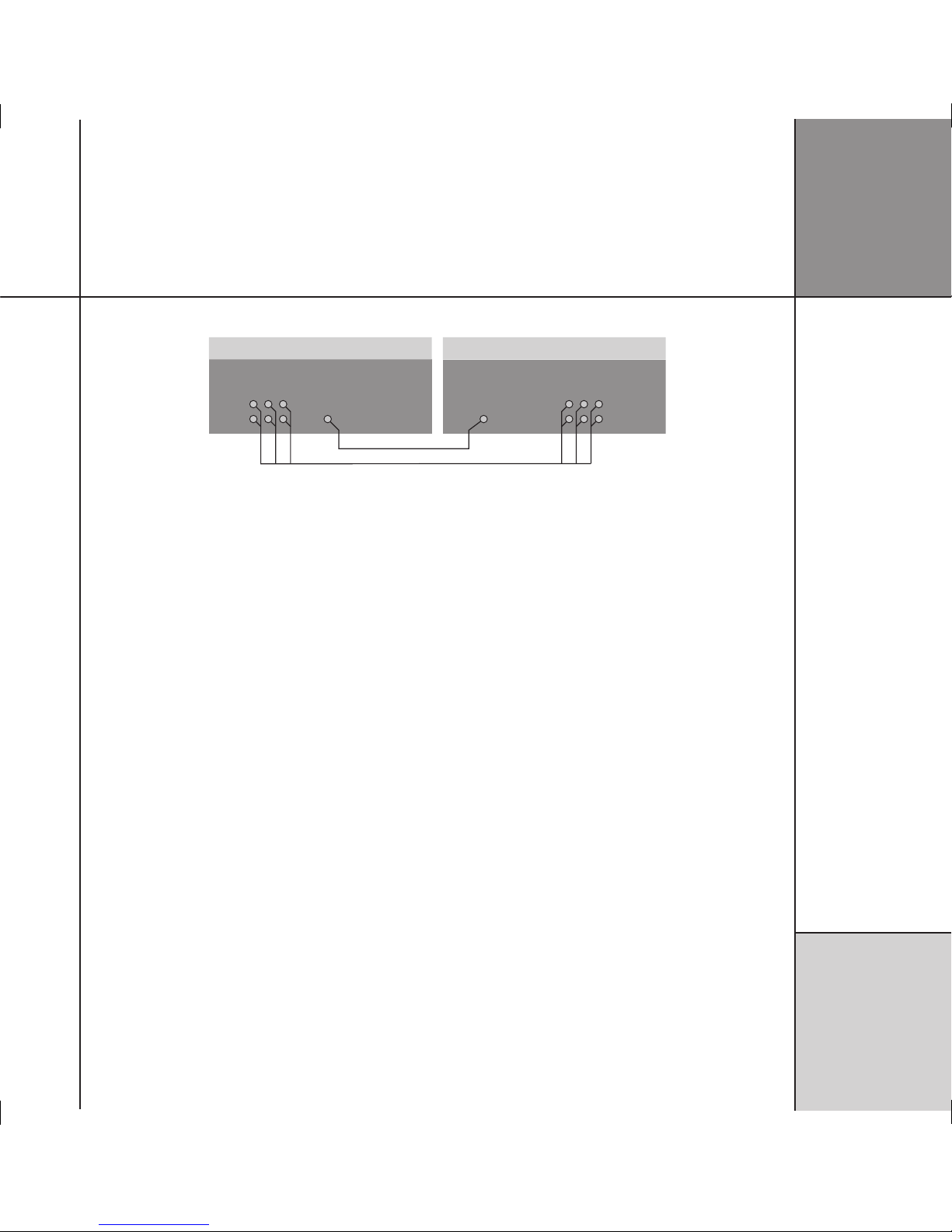
To connect to other Meridian C Series, G Series, or 800 Series equipment
COMMS
COMMS LEAD COMMS LEAD
C Series, G Series, or 800 Series unit
COMMS
C61R Digital Surround Controller
In a system of Meridian products the products should be linked
together in a chain, via the COMMS sockets, using the Comms
leads supplied with each product. The sequence in which you
connect the units is not important.
One of the products acts as the controller for the system, receiving
infra-red commands from the MSR+, and then, if appropriate,
relaying them to the other products via the Comms link. The
following procedure should be used to set up the Comms correctly
between several products:
• Switch all the units to standby.
• Press
Clear (MSR+).
Each unit will display:
Auto
One unit will then be designated as the controller, and display:
Con.
All the other units will be configured as non-controllers, and
display:
Not Con.
The system is now ready for use.
If the automatic setup does not work, first make sure you are
operating the MSR+ from a position where all the units can receive
the infra-red, and try again. Then:
• Check that none of the units have been configured to be IR
Controller; see
Settings
, page 25. Either all products should be
set to Auto, or one should be configured as Controller and the
others as Not Controller.
Note: Do not, under any circumstances, connect any equipment
other than Meridian C Series, G Series, or 800 Series to any socket
marked COMMS on the back of the product.

I ns t a l li n g t h e
d ig i t a l s ur r o u nd
c on t r o ll e r
1 6
C on f i g ur i n g t h e
d ig i t a l s ur r o u nd
c on t r o ll e r
1 7
Configuring the digital surround controller
This chapter explains how to configure the digital surround controller using the Configuration Wizard.
Alternatively, for complete control over all aspects of the product’s configuration you can set up the unit
from a computer using the Meridian Configuration Program; see
Meridian Configuration Program
,
page 35.
Configuration Wizard
The Configuration Wizard leads you through the correct
sequence to configure your digital surround controller. Alternatively,
you can skip between the configuration stages, which allow you to
reset the configuration, or configure the sources or other settings
of the digital surround controller.
To run the Configuration Wizard
• If necessary press
On/Off to put the digital surround controller
into standby.
• Press
More.
If the product is locked the display shows:
5NLOCK6ERSION
• Press Unlock to unlock it, then press More.
The displays then shows:
,OCK#ALIB6ERSION )2 7IZARD
• Press Wizard.
Follow the sequence of configuration stages described in the
following pages, pressing Next to proceed after each stage.
At any stage in the Configuration Wizard the following options are
available:
To do this Press
Go back to an earlier configuration option Back
Return to the title screen for the stage Home
Exit from the configuration menus On/Off
Display help about the current option More
C on f i g ur i n g t h e
d ig i t a l s ur r o u nd
c on t r o ll e r
1 8
The digital surround controller provides several alternative standard
settings, called Types, which configure all aspects of the product
into the most commonly needed configurations.
Choosing one of the Types overrides any other configuration you
may have performed, and so can be used to reset the configuration
of the unit.
To reset the configuration
• Press
Wizard.
The display shows the title screen for stage 1:
%NTER 3KIP"ACK
0RESS-OREFORHELP
2ESETSETTINGS
• Press Enter to proceed or Skip to go stage 2.
If you pressed Enter the display shows:
"ACK 9ES
2ESETALLSETTINGS
• Press Yes to proceed or Back to exit.
The display shows the current Type:
"ACK .EXT z{|wxy
!LL!N-ONO4(83UB
4YPE
• Press A or V to step through the available Types.
A description of the speakers for each type is shown on the top
line of the display. As you select each Type the digital surround
controller is reset to that Type.
When you have selected the Type you want:
Either:
• Press Next to proceed to configuring speakers, as described in
the next section.
Or:
• Press On/Off to return to standby.
Stage 1: Resetting the product

C on f i g ur i n g t h e
d ig i t a l s ur r o u nd
c on t r o ll e r
1 9
Types
The following table lists the available Types:
Type Speakers Music Sub Logic Sub 5.1 Movie Sub
0 All analogue. LFE Centre LFE
1 All analogue. Mono Mono Mono
2 All digital. LFE Centre LFE
3 All digital, large centre. None None None
4 Digital left, right, and centre. LFE Centre LFE
5 Digital left and right. LFE Centre LFE
Music Sub refers to a subwoofer used for all Music DSP presets, Logic Sub to a subwoofer used for all Logic DSP presets, and 5.1 Movie
Sub to a subwoofer used for all 5.1 Movie DSP presets; see
Speaker layouts
, page 85.
LFE subwoofer is only active in multichannel presets. Mono and Centre Subwoofers are active in all presets.
Note that any Types stored using the Meridian Configuration Program will also be available in this list; see the
Meridian Configuration
Program Guide
for more information
.
C on f i g ur i n g t h e
d ig i t a l s ur r o u nd
c on t r o ll e r
2 0
Stage 2: Configuring speakers
The Speakers configuration stage allows you to set up the digital
surround controller for the particular arrangement of loudspeakers
in your system.
To configure the speakers
Either:
• Press Next after resetting the product; see page 18.
Or:
• Press Wizard; see page 17.
• Press
Skip to skip past the Reset settings menu.
The display shows the title screen for stage 2:
3KIP"ACK %NTER
3ELECTSPEAKERS
0RESS-OREFORHELP
• Press Enter to proceed or Skip to go to stage 3.
The display shows the first speaker configuration option:
z{|wxy"ACK .EXT
.UMBEROF3UBWOOFERS
ONE
• Press Next or Back to step between options.
A description of each option is shown on the top line of the
display, and its current value is shown below this to the right.
The options are summarised in the table on the next page.
To change an option
• Press
A or V to step between the alternative values for the
option.
When you have stepped through all the speaker options the display
shows:
"ACK .EXT
3PEAKERCHOICEFINISHED
Either:
• Press Next on the last option of the last speaker to proceed to
configuring sources, as described in the next section.
Or:
• Press On/Off to return to standby.
If you press On/Off before completing the configuration a warning
is displayed, giving you the option of continuing or abandoning the
configuration.

C on f i g ur i n g t h e
d ig i t a l s ur r o u nd
c on t r o ll e r
2 1
Speaker options
The following table summarises the speaker options:
Option Values Description
Number of Subwoofers: none, one, two, three How many subwoofers.
The main L&R speakers are: small analogue/THX, small DSP, large
analogue, large DSP
The types of the main left and right speakers. If you have no
subwoofers, you cannot specify small main speakers.
The Centre is used: always, never, for music, for movies When the centre speaker is to be available.
The Centre speaker is a: small analogue/THX, small DSP, large
analogue, large DSP
The type of the centre speaker.*
Number of Surrounds: none, two, four The total number of rear and side surround speakers.
The Side speakers are: small analogue/THX, small DSP, large
analogue, large DSP
The types of the side speakers.*
The Rear speakers are: small analogue/THX, small DSP, large
analogue, large DSP
The types of the rear speakers.*
The Subs are used: for movies only, always When the subwoofers are used. If you have small main speakers,
the subwoofer must always be used.
The Sub handles: all the bass, only the LFE Whether to use the subwoofer for all bass or just the LFE channel.
Only available if there is only one subwoofer.
The bass balance is: neutral, heavy Whether the bass is distributed to all the large speakers and
subwoofer (heavy) or just the subwoofer (neutral – recommended).
Only available if there is only one subwoofer, and it handles all the
bass not just the LFE.
The 2 Subs are used for: Left and Right, Front and Surround If there are two subwoofers, their position. Only available if there
are two subwoofers.
The sub is: analogue, digital The type of subwoofer(s).
*If you have small main speakers, you cannot specify large centre or surrounds.
C on f i g ur i n g t h e
d ig i t a l s ur r o u nd
c on t r o ll e r
2 2
Stage 3: Configuring sources
The digital surround controller provides up to 12 sources
corresponding to the 12 source keys on the MSR+:
CD, RADIO, DVD, AUX, DISC, TAPE, TV, CABLE, SAT, VCR1, VCR2,
GAME.
For each source the Configure sources stage allows you to
configure a series of options, including:
• Whether it is in use.
• The label used for it on the front-panel display.
• The audio input it selects.
• The TRIGGER output level it selects.
The procedure for doing this is as follows.
To configure a source
Either:
• Press Next after configuring speakers; see page 20.
Or:
• Press Wizard; see page 17.
• Press
Skip to skip past the Reset settings and Select
speakers menus.
The display shows the title screen for stage 3:
3KIP"ACK
0RESS-OREFORHELP
%NTER
#ONFIGURESOURCES
• Press Enter to proceed or Skip to go to stage 4.
The display shows the first source and the first configuration option
for that source, whether it is in use:
z{|wxy"ACK .EXT
4HISSOURCEIS
3OURCE
#$ INUSE
• Press Next or Back to step between options.
The top line of the display shows a description of each option, and
its current value is shown to the right of the source name.
When changing the source name, Next and Back step between
character positions.
The options are summarised in the table on the next page.
To change an option
• Press
A or V to step through the alternative values for the
option.
To move to the next source
• Press
Source.
When you have finished configuring sources:
Either:
• Press Next on the last option of the last source (Game) to
proceed to configuring settings, as described in the next section.
Or:
• Press On/Off to return to standby.

C on f i g ur i n g t h e
d ig i t a l s ur r o u nd
c on t r o ll e r
2 3
Source options
The following table summarises the source options:
Option Values Description
The source is: in use, not in use Whether the source is enabled.
Audio input: D1-D12, MD1-MD2, U1, O2-O5, A1-A8,
MA1, MA2, Last Valid*
The audio input used for the source; digital, multichannel digital,
USB, optical, tuner, analogue, or multichannel analogue.
Source name: Any name of up to five characters.
Trigger #1: High, Low, Last Valid Trigger outputs for the source.
Trigger #2: High, Low, Last Valid Trigger outputs for the source.
Trigger #3: High, Low, Last Valid Trigger outputs for the source.
Comms Type: CD 1C, Tuner 2C, DVD 3C, 4C-8C,
No Comms NC
Set to NC unless the source is a Meridian product.
Comms Address: 1A-8A Allows you to have up to eight of each source type.
*Last Valid leaves the input set to the last input you selected.
C on f i g ur i n g t h e
d ig i t a l s ur r o u nd
c on t r o ll e r
2 4
The next stage allows you to configure other aspects of the
product’s operation.
To configure other settings
Either:
• Press Next after configuring the sources; see page 22.
Or:
• Press Wizard; see page 17.
• Press
Skip to skip past the stages 1 to 3.
The display shows the title screen for stage 4:
3KIP"ACK %NTER
/THERSETTINGS
0RESS-OREFORHELP
• Press Enter to proceed or Skip to go to the calibration
procedure.
The first setting is displayed:
z{|wxy"ACK .EXT
4HEFANIS
USEDASNECESSARY
A description of each setting is shown on the top line of the
display, and its current value is shown to the right of the display.
The settings are summarised in the table on the next page.
To change a setting
• Press
A or V to step through the alternative values for the
setting.
When you have finished configuring the settings:
Either:
• Press Next to proceed to calibrating the system, as described in
the next chapter.
Or:
• Press On/Off to return to standby.
Stage 4: Configuring other settings
 Loading...