

Page 1

MERIDIAN 562 USER MANUAL
Meridian Audio Ltd
14 Clifton Road
Huntingdon
Cambs. PE18 7EJ
England
Tel (0) 480 52144
Telex 32577 (MERIDN)
Fax (0) 480 459934
Meridian America Inc.,
3800 Camp Creek Parkway
Building 2400, Suite 112
Atlanta, GA 30331
Tel. (404) 344-7111
Fax (404) 346-7111
©
Meridian Audio Ltd Meridian Audio Ltd
, 1993
Page 2

2
601 User Guide
Contents
Acknowledgements................................3
Introduction................................ ............5
About this manual..................................5
About the 500-Series.............................. 5
Unpacking the 562 ................................ ..6
Installing your 562..................................6
General precautions ............................6
Customising features...........................6
Connections ........................................7
Siting...................................................7
Starting off with 562...............................8
Checking .............................................8
Switching on........................................8
If there are no lights.............................8
Standby............................................... 8
Basic operation of 562 ...........................8
Selecting a source...............................8
Putting the 562 in standby ...................8
Coming out of standby.........................8
Adjusting the volume ...........................9
Muting the sound.................................9
Changing the display .........................10
Advanced operation using the
Remote Control ............................... 11
Balance control ................................ ..11
Operation summary..............................12
On the 562 front panel.......................12
With the Remote Control....................12
Customising 562, an overview.............13
Restoring default settings .................. 13
Type: an overview ............................. 13
Config: an overview...........................13
Gain: an overview.............................. 14
How to customise 562..........................15
Customising, general procedure.........15
Customising using Type...................... 16
Customising using Config................... 18
How to use Config .............................18
Setting up sources............................. 21
Customising using Gain ......................23
How to use Gain................................23
Setting the sensitivity for
analogue inputs ............................24
Audio connections...............................25
Analogue audio connections..............25
Digital audio connections...................25
Communications connections.............26
To connect to other Meridian
500 Series equipment .................. 26
Connecting digital recorders;
CDR, DAT or DCC....................... 27
Connecting analogue tape
recorders...................................... 27
Making recordings............................... 27
Using D600, DSP5000 or D6000
speakers with 562 ...........................28
200 Mode digital speakers................. 29
500 Mode digital speakers................. 30
Additional technical information ........ 31
Understanding input sensitivity
in a digital preamplifier.................. 31
Clipping and overload........................31
How to get the best out of LP............ 31
Specification ................................ ........ 33
Help! ..................................................... 34
Standby point not lit........................... 34
Audible hiss at high volume
settings........................................ 34
Poor sound quality ............................ 34
Hum on LP inputs.............................. 34
Hum on other inputs.......................... 34
Communications not working
between 562 and other
Meridian products......................... 35
Radio interference............................. 35
Cleaning ................................ ............... 35
Maintenance & Service........................ 35
Guarantee............................................. 36
Index..................................................... 37
Notes..................................................... 39
Page 3

562 User Guide
Acknowledgements
Trademarks etc.
Boothroyd|Stuart Meridian and Meridian are registered trademarks of
Meridian Audio Ltd.
Author: J R Stuart
Page 4

Page 5

Introduction 5
562 User Guide
Introduction
The Meridian 562 Control Unit is part of the 500-Series of advanced highfidelity equipment.
In purchasing a Meridian 562 Control Unit, you have acquired a refined
piece of equipment that will continue to bring you listening pleasure for
many years. This manual will enable you to get the most from it.
About this manual
506. A number such as 506 refers to a component in the Meridian 500-
Series of audio equipment.
Mute. Whenever a key name is printed in bold typeface, it means that
you should press this key. If the key name is not in bold type, it indicates that the course of action is not required at present, e.g. ‘if you
want to change the display, press Display' means you can do this, but
it is not essential as part of the operation currently being discussed.
Standby Italic form normally refers to the state of the 562. In some in-
stances, a key and the status of the equipment share the same name,
e.g. the Standby key and the Standby state.
Displays are illustrated in this form.
1. In this book, sequences of actions are given in numbered lists.
Note Some paragraphs may be in the form of notes, warnings or tips;
these sections are delineated like this one. We recommend you do not
skip these.
About the 500-Series
The Meridian 500-Series is a unique system of digital, analogue and video
components designed to meet the demand for absolute quality, ease of
use and lasting value.
The flexibility of the Meridian 500 Series is such that you can assemble a
system as simple or as complex as you need, perfectly suited to your
requirements, and with the ability to add to it or change it at a later date
should those requirements change. The 500 Series is also compatible
with the existing Meridian 200 and 600 Series components.
Each Meridian 500 Series component is housed in a matching slim line
case. Full access to all functions is provided from the front panel controls
and from the Meridian 509 or System handsets.
The Meridian 500 Series includes a sophisticated communications link, to
ensure that any configuration of units will work together as a fully
integrated system.
The 500 Series communications system allows you to control any
combination of units using a single handset, and ensures that your
commands from the handset are interpreted unambiguously. Any unit can
be designated as the controller for the system, allowing you to position the
other units out of range from the handset beam if desired. It also allows all
the units to be switched off from the front panel of any unit in the system.
RD 54
Page 6

Installing 562 6
562 User Guide
Unpacking the 562
On opening the carton, you should have found the following parts:
• Meridian 562 Control Unit
• Power cord
• This manual
• Getting going instruction sheet
• 4mm banana plug for turntable grounding
• 500-Series communications lead
If any of these items is missing, please contact your dealer. We suggest
that you retain the packing carefully as it provides maximum protection for
the unit in transit.
Installing your 562
General precautions
Before carrying out any installation, you should ensure that the 562 is
marked with the correct voltage for your local AC supply. Should this not
be the case, do not proceed – but contact your dealer.
As a general rule, you should not make any connections to the 562, or to
any other component in your system, whilst the AC power supply is connected and switched on.
Customising features
The 562 is very flexible. You have the opportunity to significantly customise its functions. In the end this gives you a preamplifier that exactly suits
you.
The Meridian 562 is not a product that you are likely to use stand-alone,
you are quite likely to be using some other Meridian components and
getting the best out of the system will require a little thought.
The section ‘Customising 562, an overview' on page 13 describes the options in detail. Obviously, when you have set up 562 to your needs, you
will be aware of the differences from the standard configurations.
We recommend that you first get to know the 562 using one of the standard setups, and by working through this manual. Do not be afraid later to
experiment with customising – we have given you a simple way to get
back to where you started! (See page 16).
562 as provided has nine standard configurations that we call Type settings. Each Type gives a different set of options; this feature is described
fully on page 16. There are many more than nine possible configurations
for 562, but these were chosen to give good starting points for
customising.
By selecting a Type you automatically reset all custom settings for 562 to
that default.
562 has five operating modes (not to be confused with setup Types):
• Normal
• Standby
• Type
• Config
• Gain
Normal and Standby are the everyday operating modes: the basic operating instructions refer to these.
For full details of
Type settings and
configuring 562,
see ‘Customising
562, an overview'
on page 13.
Page 7

Installing 562 7
562 User Guide
Type, Config and Gain are used to make choices about the way 562
works. These are described later in the section: ‘Configuring 562, an
overview' on page 13.
Connections
There are three types of connection that need to be made to the 562:
• analogue audio
• digital audio
• communications.
Audio connections need to be made to other components in your system.
Communication connections have to be made to most of the other
Meridian components in your system in order for them to act as one system. The connections to your 562 are very important and care should be
taken in deciding which connections to make.
Connection details for a wide variety of systems are described in the sections following page 25.
Siting
We recommend the following guidelines for location.
• The 562 should not be placed on top of a power amplifier.
• If you intend to use a moving coil LP input keep the left-hand-side of
the 562 as far as possible from other mains-operated equipment. See
help item on page 34.
• Avoid sites where it would be subjected to direct sunlight or where it is
near a heat source, e.g. a central heating radiator
• Avoid sites where the 562 could be subjected to strong magnetic ra-
diation, like near a power amplifier.
• Not too close to a television, or where connecting cables may be sub-
ject to, or cause, interference.
Tip In common with all digital products, the 562 emits some radio-frequency signals. For this reason, try to keep all power cables and network
leads away from audio, antenna and loudspeaker cables. Some time
spent laying out the cables carefully will repay you with the best possible
performance later.
For details of
making all connections, see
Connecting 562,
page 25.
Page 8

Using the Remote control 8
562 User Guide
Starting off with 562
Checking
Before turning on the power, check once again that you have made all the
connections correctly and that you have not disturbed any existing connections in the process.
Switching on
The power switch is located directly next to the power inlet on the rightrear of 562.
1. Turn on the power switch at the rear of the unit. A small point on the
display should now be illuminated.
If there are no lights
Check the integrity of your power connections, including any fuses in your
supply. If the standby point is still not illuminated and the rest of your
system is functioning, contact your dealer for help.
Standby
The entire 500-Series is designed to be left connected to AC power at all
times.
1. This standby state ensures that the components operate at maximum
efficiency from the moment you start listening. It is perfectly safe and
consumes a negligible amount of power. However, when you are not
going to use your system for an extended period of time, e.g. when
you are going on holiday, we would advise you to disconnect it from
the AC power supply.
Basic operation of 562
Note 562 can be used with or without Meridian
digital loudspeakers like
D600, DSP5000 or D6000. When it used alone as the main system
control unit it is normally the ‘System Controller’ and operates exactly as
described below. Systems including digital ’speakers always designate the
speakers as System Controller and there are some functional differences.
The section ‘Using digital speakers with 562' on page 28, describes how
the operation differs from the following description.
Selecting a source
1. press Source until the input you require is indicated
2. release Source
Selecting a source will bring 562 out of standby.
Putting the 562 in standby
1. press Off, the coloured key on the 562
or
press Standby on the Remote Control
Coming out of standby
To start up the 562 from standby
.
Page 9

Using the Remote control 9
562 User Guide
1. Select a source from the front panel or using the Remote Control.
Tapping Source once brings the 562 on with the last-used source
selected.
or
If the 562 is part of a Meridian
system, bring any component out of
standby. For example start up a Meridian CD-player.
Adjusting the volume
The standard 562 does not have a volume control. If you want a variable
output, making it very like a conventional preamplifier, then you need to fit
the optional DAC module. Ask your dealer for details.
When used in a system based on Meridian digital speakers which is
operating in 500 communications mode (see the explanation of this on
page ??), the volume keys on the front of 562 will operate the speaker
volume.
If you have a DAC option fitted, or are using digital speakers in 500 mode
you can adjust the volume on the front panel of the 562.
To increase the volume
1. press ,, the right-hand volume key on the 562
or
press the top red key on the Remote
To decrease the volume
1. press ,, the left hand volume key on the 562
or
press the bottom red key on the Remote Control
As you adjust the volume setting, the display will change to show the current source and volume level. For example:
would indicate that you were listening to a Compact
Disc at a volume setting of 65. The volume level dis-
played will count up or down and ranges from 1 to 99. Each step is 1dB.
If you have selected a different display, the display will then revert to your
selected information.
Subjectively a volume increase of 9dB is equivalent to a doubling of
loudness. Each volume number represents about a 11% change in loudness; nine steps to double loudness. In a traditional preamplifier using a
rotary volume control the mid-way position offered between 20dB and
30dB of attenuation. On 562 20dB attenuation is at volume number 79,
30dB at 69. For normal to high-level listening you should expect volume
numbers in the region 60 to 90. For this reason 562 starts at power-up
with volume number 70.
Note When 562 is set up for use with D600, DSP5000 or D6000; volume,
balance and mute are handled by the speaker and 562 will not respond to
the Remote control.
Muting the sound
The mute facility cuts off the sound by setting the volume level to zero.
To mute the sound
1. Press Mute on the 562 or the Remote Control. The output will mute
and the display will change to:
CD65
Page 10
Using the Remote control 10
562 User Guide
To restore the sound
1. Press Mute a second time, either on the 562 or the Remote Control.
The volume level and display will be restored.
or
Use the Volume keys.
Note When 562 is set up for use with D600 or D6000; volume, balance,
phase and mute are handled by the speaker and 562 will not respond to
the Remote control.
Changing the display
The 562 has three display modes. To change the display:
1. Press Display.
The 562 will cycle through the displays:
• Source and first volume number
• Source only
• Display blank
Note When 562 is set up for use with D600 or D6000 the 562 display can
only be changed on its front panel. The Display key on the Remote control
will control the speaker display.
Tape Copy
562 can be arranged to feed any one of the standard sources to the tape
outputs independently of the source to which you are listening. Where
possible the tape signal will be available on both the analogue and digital
tape outputs.
Note Depending on whether you have fitted the DAC option, or on
whether you have connected both analogue and digital outputs of your
source products, there may be circumstances where some combinations
of different sources may not be listened to and copied simultaneously.
This is explained in detail on page ??
To change the copy setting:
1. Press Copy.
The 562 will cycle through the options:
• CSrc, meaning Copy Source – i.e. what you are listening to
• CAtt, meaning Copy Attenuate. Tape outputs are muted.
• C CD, then a series of options to copy specific sources, depending
on the Type setting or specific Gain.
Note Copy can also be used to provide a second independent output from
562 for 2-room or simple Multiroom applications.
Information reviewed in standby
1. Press and hold Display.
The display will show the version number of the microcontroller
software, e.g.:
Mute
V.1.0
Page 11
Using the Remote control 11
562 User Guide
Advanced operation using the Remote Control
Balance control
The balance can only be adjusted from the Remote control.
Note 562 only has a balance feature if you have fitted the optional DAC
module and correctly configured the unit. See page ?? for more details.
Note When 562 is set up for use with D600 or D6000; volume, balance,
phase and mute are handled by the speaker and 562 will not respond to
the Remote control.
To move the sound to the left
1. Press Left
The display will show the current balance, e.g.
The number indicates the number of dBs
advantage given to the left channel.
To move the balance back again
1. Press Right until the display says:
or
Press Reset (also only on the Remote control)
To move the sound to the right
1. Press Right
The display will show the current balance, e.g.
The number indicates the number of dBs advantage
given to the right channel.
Note When 562 is set up for use with D600 or D6000; volume, balance
and mute are handled by the speaker and 562 will not respond to the
Remote control.
←←
1
←←
0
→→
9→→
Page 12

Operation summary 12
562 User Guide
Operation summary
On the 562 front panel
Key Action
Source
Select or review the sources available.
Copy
Select or review the Copy function.
Display
Cycle the display through:
source and volume number
source
display off.
Mute
Switches between mute and demute.
Volume Down
Decrease the volume.
Volume Up
Increase the volume.
Off
Puts the 562 into the standby state.
With the Remote Control
Source keys
Selects input depending on customisation.
Standby
Puts the 562 into the standby state.
Display
As on front panel
Reset
Restore balance
< Left
Moves the balance to the left
> Right
Moves the balance to the right
Red
∧∧ and ∨∨
Change the primary volume.
Mute
Mutes output.
Page 13

Customising 562: overview 13
562 User Guide
Customising 562, an overview
562 is a very sophisticated device with a huge number of options to allow
you to set up exactly the system you need or to experiment with new
possibilities.
Programming 562 is a straightforward process and you should not be
timid about experimenting. Although the setup is stored in non-volatile
memory called EEPROM, the EPROM (which you cannot change)
contains default Type settings and you can return to these at any time.
Restoring default settings
1. Switch off any power amplifiers that are connected to 562.
2. Switch off the 562 using the power switch on the back.
3. While pressing the Off key on the 562 front panel, switch the power on
again. The display will read:
4. Release the Off key
At this stage you can change the Type from 1 – 6 using the ▲ and ▼
Volume keys; see details on page Error! Bookmark not defined..
5. Switch off the 562 using the power switch on the back.
6. After half a second, switch the 562 power on again.
Caution Some power amplifiers are very susceptible to small surges that
may result from the process of switching a preamplifier on and off. Some
– like the Meridian 205 or 605 incorporate DC-offset protection that may
be triggered by this process. Meridian active or digital loudspeakers are
inherently proof against these surges and need not be switched off. In
general digital products like power amplifiers, recorders etc. will be
unpredictable when they have the digital signal interrupted.
562 has three setup options; Type, Config and Gain. These together with
Normal and Standby give the 562 five operating states. The following
sections give an overview.
Type: an overview
Type just described, restores one of the default settings. No further
actions are possible.
Config: an overview
Config mode is used for setting fundamentals of options and control.
Consequently in Config the outputs of 562 are muted while you make the
necessary choices. The choices available in Config are outlined in the
following sections.
Config: control settings
In Config you can make selections that effect the way 562 responds to
certain keys. The main choices of this kind are:
• whether you use 500 or 200 communications protocol in the system.
See page ??.
• whether the 562 is to auto-configure, or you will determine the
controller in the system. See page 28.
• The ‘address’ of the product.
• whether or not there is an internal or external DAC fitted.
• choices on how the volume control works.
• how the product treats the handset ‘Menu’ keys
Type
1
The Type
settings are
described in
detail on page
Error!
Bookmark not
defined..
To use Config,
see page 18.
Page 14

Customising 562: overview 14
562 User Guide
• whether the unit has video switching
• whether there is a Meridian CD player in 200 mode. See page Error!
Bookmark not defined..
Details of these are described in the sections referred to.
Config: sources and inputs
In Config you can also make selections to do with sources, e.g.
• how many inputs will be active
• which sources you can select
• which key on the remote control selects which source
• the Logo for that input on the 562 display
• the physical input connection to 562 including by implication whether
they are analogue or digital.
• the secondary analogue input for any digital source
• the comms type of the source, i.e. whether it is a Meridian controllable
source like CD or Radio
• the address for that source product
Gain: an overview
Gain mode is quite different from Type or Config in that the preamplifier
actually functions in this mode. In Gain the front panel controls operate
normally – with the exception of the Volume keys.
Gain is used to adjust the level of analogue sources fed to the A/D
converter.
Digital inputs have a fixed sensitivity defined by the digital data. Analogue
inputs however should have their levels adjusted so that the best use is
made of the dynamic range of the Analogue–to–Digital converter built in to
562. Best results will be obtained if the analogue gain for each input is set
to provide the largest signal that does not cause overloading or clipping.
The ‘flat response' analogue inputs like Radio, Video etc. have four
choices for sensitivity; 0.5V, 1.0V 2.0V and 2.5V for full-scale. Phono
inputs using the optional Moving-Coil or Magnetic (MC or MM) module in
input A1, also have four settings.
Note An important feature of Gain is that you can adjust the analogue
input and output settings while listening to the music. When you feel you
have the correct combination of settings you can revert to Normal which
protects the settings.
Note The input sensitivities for the 562 digital preamplifier are not
expressed in the same way as those for analogue counterparts. Caution
should therefore be used in comparing these sensitivities. The input level
for the 562, in common with other digital equipment is expressed in terms
of full-scale in the digital signal – i.e. more equivalent to the input overload
point of an analogue preamplifier. See specifications on page 33.
To use Gain, see
page 23.
For more details
on analogue input
levels see page
Error!
Bookmark not
defined..
Page 15

Customise 562 using Type 15
562 User Guide
How to customise 562
562 needs no customising to become operational. Once you have your
system established you may wish to review the customising options in the
section ‘Customising 562, an overview', page 13.
Although the 562 comes configured as a standard digital + analogue –
digital preamplifier, there are a very large number of different
configurations possible. This section tells you how to change the
configuration.
Customising, general procedure
562 has five operating modes (not to be confused with setup Types):
• Normal
• Standby
• Type
• Config
• Gain
Normal and Standby are the everyday operating modes: the basic
operating instructions refer to these.
Type, Config and Gain are used to make choices about the way 562
works. These are described in the section: ‘Configuring 562, an overview'
on page 13.
How to change to Type, Config or Gain
To change to Type, Config or Gain you use the same basic procedure.
1. Switch off any power amplifiers that are connected to 562.
2. Switch off the 562 using the power switch on the back.
3. While pressing the specific key for the operating mode you want on the
562 front panel, switch the power on again.
562 will display a message to inform you which mode it is in.
4. Release the key
At this stage you can make the adjustments required.
In step 3, the front panel key is:
• Type – press and hold Off.
• Config – press and hold Display.
• Gain – press and hold Mute.
• Normal – do not use any key!
Caution Some power amplifiers are very susceptible to small surges that
may result from the process of switching a preamplifier on and off. Some
– like the Meridian
205 or 605 incorporate DC-offset protection that may
be triggered by this process. Meridian active or digital loudspeakers are
inherently proof against these surges and need not be switched off. In
general digital products like power amplifiers, recorders etc. will be
unpredictable when they have the digital signal interrupted.
How to change back to Normal
To revert to Normal .
1. Switch off the 562 using the power switch on the back.
2. After half a second, switch the 562 power on again.
Page 16

Customise 562 using Type 16
562 User Guide
A full customising process
A full customising process will generally involve using all the configuring
modes of 562. A full procedure is as follows.
1. Change to Type and select the configuration closest to your
requirements.
2. Change to Config and make choices about:
• keys, displays, inputs.
• control options
3. Change to Gain and make choices about:
• analogue input sensitivity.
4. Change back to Normal.
Making changes to an existing setup
Config and Gain are configuration editing modes, they do not reset on
entry. Type however performs a full reset of all parameters.
To make any changes to your custom configuration:
1. Change to Config or Gain – whichever is appropriate,
2. make the changes you want,
3. change back to Normal.
Customising using Type
Type is a mode used specifically to setup 562 into one of nine factorypreset configurations. Type resets the following for all six Types.
• Balance to central.
• Depending on the Type selected, the communications settings will be
as follows:
Type Mode DAC ? Sources CD ?
1 500 N 12 –
2 200 N 8 Y
3 500 N 6 –
4 500 N 8 –
5 500 V
1
12 –
6 500 V
1
8 –
7 500 T
1
12 –
8 500 T
1
8 –
9 200 N 8 N
For an overview
of Type, see
page 13.
Page 17

Customise 562 using Type 17
562 User Guide
• Source-Logo-input mapping as shown below.
Source Logo Input 2nd i/p Gain Comms
type
CD CD D1 A2 2.5V 1
Radio RD A3 N 2V 2
LP LP A1 N +2dB –
TV TV A4 N 1V –
Tape1 T1 A5 N 2V –
Tape2 T2 D2 N – –
CDR CR D3 N – –
Cable Cb A6 N 1V –
Text Tx LV
2
N n/a –
VCR1 V1 A7 N 1V –
VCR2 V2 A6 N 1V –
LD LD A4 N 2V –
Selecting Types
1. Switch off any power amplifiers that are connected to 562.
2. Switch off the 562 using the power switch on the back.
3. While pressing the Off key on the 562 front panel, switch the power on
again. The display will read:
4. Release the Off key
5. Use the front-panel
and Volume keys to move the selection
between Types 1 – 9.
6. When you have the Type you want displayed, wait one second for 562
to action the choice.
7. Switch off the 562 using the power switch on the back.
8. After half a second, switch the 562 power on again to restore Normal
mode.
Type
1
Page 18
Customising 562 using Config 18
562 User Guide
Customising using Config
In Config you can review and change settings to do with communications,
control and the hardware options you have. In Config you also make
choices about the number and types of sources, what the display shows
when you select them etc. The 562 is initially programmed to Type 1 and
all Types set up the source configuration as shown in the previous Tables.
How to use Config
1. Switch off any power amplifiers that are connected to 562.
2. Switch off the 562 using the power switch on the back.
3. While pressing the Source key on the 562 front panel, switch the
power on again. The display will read:
4. Release the Source key, the display will show:
Selecting comms mode
In Config mode:
1. Press Copy until you see a display like:
1. Use the
and ,, Volume keys to choose 500 or 200
For guidance on this question see Page ??.
Selecting the controller mode
In Config mode:
1. Press Copy until you see a display like:
2. Use the
and , Volume keys to choose between:
• Auto, meaning configuring can be automatic
• Cont, meaning the 562 will be the system controller
• NCon, meaning the 562 will not be the controller
For guidance on this question see Page ??.
Note This setting has no meaning in 200 comms mode
Setting the system address for 562
In Config mode:
1. Press Copy until you see a display like:
This means the system address is 1. The Meridian 500 comms system
allows for up to eight systems operating on the same network. Unless you
are setting up a Multiroom system, or are advised to do so by Meridian
support personnel, we suggest you leave this on address 1.
Note This setting has no meaning in 200 comms mode
Setting the product address for 562
In Config mode:
1. Press Copy until you see a display like:
For an overview
of Config, see
page
13
Conf
500
For more details
of comms mode
see page ??.
500
Auto
SA=1
PA=1
Page 19
Customising 562 using Config 19
562 User Guide
This means the product address is 1. The Meridian 500 comms system
allows for up to eight products of the same type operating on the network.
Unless you are setting up a Multiroom system, or are advised to do so by
Meridian support personnel, we suggest you leave this on address 1.
Note This setting has no meaning in 200 comms mode
Note When customisation is complete, switch the power off and then on
again to restore Normal mode and to save what you have done.
Setting the DAC mode for 562
In Config mode:
1. Press Copy until you see a display like:
This means there is no internal DAC (digital–to–analogue converter)
option fitted and that you have not fitted an external DAC.
For guidance on this question see Page ??.
2. Use the
and , Volume keys to choose between:
• DACT, either an external DAC (like the Meridian 203, 263 or 563) is
connected between the second digital output Do2 and the DAC
socket (used as an input), or, an internal DAC option will be
configured in Tape mode. This mode guarantees that any source
can be copied to the analogue tape outputs irrespective of the
listening source or secondary inputs.
• DACV, internal DAC option only. The internal DAC has a variable
output, that appears on the DAC socket. Use this setting if you
want 562 to function as an analogue-output preamplifier with
volume control from the remote control and front panel.
• DACF, internal DAC option only. The internal DAC has its output
fixed at 2V and the output that appears on the DAC socket. Use
this setting if you want a fixed-level analogue copy of the main
digital output.
• DACH, internal DAC option only. The internal DAC has a variable
output, that appears on the DAC socket. In this case the output
level is controlled only by the volume keys on the front panel of
562, and this setting is ignored by the rest of the installation. Use
this setting to drive headphones from the DAC output.
For guidance on this question see Page ??.
Setting the Volume mode for 562
In Config mode:
1. Press Copy until you see a display like:
In the 500 comms system there is provision for two volume controls, main
and secondary.
NDAC
VolM
Page 20
Customising 562 using Config 20
562 User Guide
2. Use the
and , Volume keys to choose between:
• VolM. Volume main means that the volume control in the DACV
option (above) will follow the main system and respond to the red
keys on the remote. Shifted (secondary) volume commands will be
passed on to another product.
• VolS. Volume secondary means that the volume control in the
DACV option (above) will follow the second volume control in the
system and respond to the shifted volume command on the remote.
An example of an application of this would be where 562 is not the
controller – as for example in a D5000 system – and you want to
change the 562 variable output from the remote control.
For further details on shifted commands see the manual supplied with the
remote control.
If you do not have a DAC fitted this setting is ignored. If in doubt choose
VolM.
Setting the Menu mode for 562
In Config mode:
1. Press Copy until you see a display like:
In the 500 comms system there is provision for the menu key (remote
control) instructions to be passed on by the controller, either because it
does not use menus, or because a shifted menu command has been
created.
N means that menu instructions received from a controller (like a
D5000) will be ignored.
For further details on shifted commands see the manual supplied with the
remote control.
2. Use the
and , Volume keys to choose between:
• 1. Shifted menu instructions ( in this case only and ) will
be used to adjust the balance.
• 2. Shifted menu instructions ( in this case only and ) will
be used to adjust the balance.
Setting a Video version
In Config mode:
1. Press Copy until you see a display like:
2. Use the
and , Volume keys to choose between 562 and 562V.
If your 562 has a video board fitted, always chose 562V.
200-Series mode CD player?
In Config mode:
1. Press Copy until you see a display like:
2. Use the
and , Volume keys to choose between CD?Y and CD?N.
a. is there a Meridian CD player?
b. is the network operating in 200 mode?
c. is 562 the system controller?
If the answer to a, b and c is yes, choose CD?Y otherwise pick CD?N.
N
562
CD?N
Page 21

Customising 562 using Config 21
562 User Guide
Setting up sources
For each of the twelve source selection keys on the Remote control you
choose a display Logo and a primary physical input connection – and by
implication – signal type. In addition for digital sources you may set up a
secondary analogue input connection that 562 may use for the analogue
tape copy signal. (This is necessary if you do not have the DAC option
fitted or externally connected – see page ??).
Normally as shown we set the CD key to give a CD display with the D1
(Digital 1) input selected. You may however wish to display CD1 for your
main CD player and to connect it to D2 or one of the analogue inputs.
A full list of possible logos and their meanings is:
Source Logo Source Logo Source Logo
CD CD S-VHS SV DAB DB
Radio RD Betamax
βm
Dig. Sat. DS
LP LP Camera Ca ADC AD
Tape 1 T1 Video 8 V8 R-Reel RR
Tape 2 T2 CD-Video CV FM tuner FM
CDR Cr CD-I CI AM tuner AM
Cable Cb CD trans. C1 MW tuner MW
Teletext TX Photo CD PC SW tuner SW
VCR 1 V1 CD Lib. CL LW tuner LW
VCR 2 V2 Jukebox JB Line Li
Laserdisc LD CD-ROM Rm Mic. Mi
Satellite SA DAT DT Aux Au
CDX C2 DCC DC Mixer Mx
78 rpm 78 Phono Ph Simul. SB
VHS VH MiniDisc VH Computer PC
Choosing source logos
Note at any time in the source configuring process you can use the
handset Mute key to return to the root menu with a display like ‘500’ or
‘200’.
In Config mode:
1. Press Source until you see a Remote-key (source) + logo display like
2. Press Source until the Remote key name for the source you wish to
configure is displayed.
3. Use the
and Volume keys until the correct logo is indicated – see
the list above.
4. Make changes for all the source options.
CD CD
Page 22
Customising 562 using Config 22
562 User Guide
None If you select the logo ‘N’ the 562 will ignore that key on the Remote
control and that source will not be offered in the Normal source menu.
Changing the input for a source
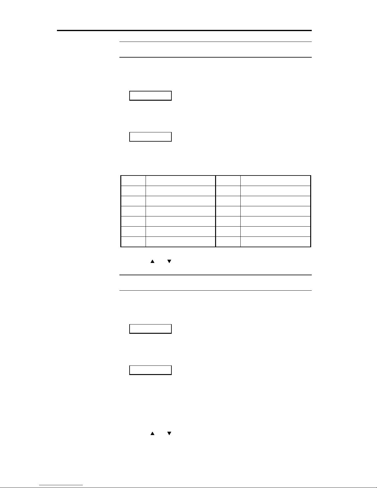
In Config mode:
1. Press Source until you see a Remote-key (source) + logo display like
2. Press Source until the Remote key name for the source you wish to
configure is displayed.
3. Press Display.
you should see the display change to one like:
The Remote control key you are setting up is the source name and it is
indicated on the left as before. Now the letters on the right indicate which
physical input connector will be selected.
A full list of physical inputs and their labelling is:
D1
Digital 1, CD
A1
Analogue 1,
D2
Digital 2,
A2
Analogue 2,
D3
Digital 3,
A3
Analogue 3,
D4
Digital 4,
A4
Analogue 4,
D5
Digital 5,
A5
Analogue 5,
A6
Analogue 6,
DAC A7
Analogue 7,
To change the physical inputs:
1. Use the
and Volume keys until the correct one is indicated
2. Make changes for all the source options by pressing Source.
Note When customisation is complete, switch the power off and then on
again to restore Normal mode and to save what you have done.
Changing the second input for a digital source
In Config mode:
1. Press Source until you see a Remote-key (source) + logo display like
2. Press Source until the Remote key name for the source you wish to
configure is displayed.
3. Press Display twice.
you should see the display change to one like:
The Remote control key you are setting up is the source name and it is
indicated on the left as before. Now the letters on the right indicate which
analogue input connector will be selected when a digital source like CD is
required on the analogue tape outputs (no DAC fitted).
In this display E means Extra input and to use it you have to connect an
analogue output from the source to one of the analogue inputs A1–A7. E1
means use A1 as an extra input and so on.
1. Use the
and Volume keys until the input you want (E1–7
corresponding to A1–7) is indicated
2. Make changes for all the source options by pressing Source.
CD CD
CD D1
CD CD
CD E1
Page 23

Customising 562 using Config 23
562 User Guide
Note When customisation is complete, switch the power off and then on
again to restore Normal mode and to save what you have done.
Choosing the comms type for a source product
This setting currently only applies to a source which is a Meridian CD
player or Radio tuner.
In Config mode:
1. Press Source until you see a Remote-key (source) + logo display like
2. Press Source until the Remote key name for the source you wish to
configure is displayed.
3. Press Display until you see display like:
1. Use the
and Volume keys to chose the comms type.
CD players are always 1C, tuners are always 2C. NC means the source is
not Meridian.
2. Make changes for all the source options by pressing Source.
Choosing the address of a source product
In Config mode:
1. Press Source until you see a Remote-key (source) + logo display like
2. Press Source until the Remote key name for the source you wish to
configure is displayed.
3. Press Display until you see display like:
1. Use the
and Volume keys to chose the product address. By
setting this, you can have up to eight of each source connected to 562
and select and control each one independently.
2. Make changes for all the source options by pressing Source.
Customising using Gain
In Gain the 562 operates as a preamplifier and you can adjust the input
levels whilst listening.
How to use Gain
1. Switch off any power amplifiers that are connected to 562.
2. Switch off the 562 using the power switch on the back.
3. While pressing the Mute key on the 562 front panel, switch the power
on again. The display will show:
4. Release the Mute key, the display will show the normal Standby
condition:
5. Now use the 562 normally until you are happy with the selections
described in this section.
6. When customisation is complete, switch the power off and then on
again to restore Normal mode. In Normal mode the settings you have
CD CD
CD 1C
CD CD
CD 1A
Gain
.
Page 24

Customising 562 using Gain 24
562 User Guide
made will be retained and cannot be changed without going back to
Gain.
Setting the sensitivity for analogue inputs
Analogue inputs to 562 are converted to digital signals in a precision
Analogue–to–Digital (A/D) converter. The best results will be obtained if
the largest possible signal is fed to the A/D converter. To allow this to
happen we have provided adjustable analogue input sensitivity.
By setting the sensitivity you also arrange for all sources to be
approximately equivalent in volume when you switch between them.
To help you set the inputs we have provided a red light on the front panel
labelled ‘Level'. The Level light illuminates when the peak input signal is
3dB below (about 70%) full scale.
To change the sensitivity of analogue inputs
In Gain:
1. Choose the first analogue input you want to adjust, e.g. select Radio.
2. Use the < and > blue keys on the Remote control to find the analogue
input-voltage configuring menu. It looks like:
In this case the Radio input will have a sensitivity of 1.0Vrms for fullscale.
3. Use the
and Volume keys on the front panel to select levels of
0.5V, 1V, 2V or 2.5V.
4. Use the 562 to listen to a wide range of material – in this case try a
few radio stations. Set the sensitivity to the lowest voltage that you
can. A good setting is the lowest one where the Level light flashes
rarely or never.
5. Repeat this process for the other analogue inputs.
6. When customisation is complete, switch the power off and then on
again to restore Normal mode.
Here are some guidelines:
• Meridian 204; use a sensitivity of 1V.
• Meridian 504; use a sensitivity of 2V.
• Inputs from fixed-level digital sources like CD players, D/A converters,
digital tuners etc.; use 2.5V.
• Inputs from tape recorders or VCRs; start with 2V.
The strongest reason to have the maximum input fed to the A/D converter
is to have a good loudness match between analogue and digital sources.
The 562 signal path analogue–analogue has a full 16bit dynamic range. It
will be most unusual for an analogue signal to have this dynamic range.
For example FM radio is equivalent to 13bits and vinyl LPs only achieve
the equivalent of 11bits. If you are particularly concerned not to overload
the A/D converter then experiment with lower sensitivities (i.e. bigger
voltage numbers). See also page 31.
For details on
how to best
adjust the
sensitivity of the
LP input for
turntables, see
‘How to get the
best out of LP’ on
page 31.
RAD
1.0V
Page 25

Technical information 25
562 User Guide
Audio connections
There are four types of connection that need to be made to the 562.
• power, see page 8.
• analogue audio, see page 25.
• digital audio, see page 25.
• communications, see page 26.
Analogue audio connections
Analogue connections are made:
• from analogue sources to the analogue inputs of the 562
• from analogue outputs of 562 to your power amplifiers, active
loudspeakers or analogue recording devices like tape-recorders.
Analogue high-level inputs
Analogue inputs should be connected using high-quality screened cable.
For advice on the type of cable we suggest you consult your dealer and
the manual supplied with the source equipment.
Warning. We strongly recommend the use of well-screened coaxial
cable. Certain ‘audiophile' cables are not screened. Screened cable will
minimise RF interaction with your system and will give more predictable
results.
1. Make analogue connections from each of your sources to an
appropriate analogue input on 562. Take care to connect Left and
Right correctly. The normal conventions are:
• left channel is the top one of a pair.
• right channel is marked red.
The analogue inputs to 562 are labelled A1–A7. These inputs are
electrically identical and can have their sensitivity adjusted in Gain. An
exception to this is if you have fitted a phono option, in which case A1 will
have sensitivities appropriate to Moving Magnet (MM) or Moving Coil
(MC) cartridges.
Turntable connection
1. Connect the pickup connections to the 562 input labelled A1 and be
sure that in Config the logo chosen is ‘LP’.
2. Connect the turntable or tone-arm ground wire to the technical ground
socket next to the A1/LP input using the 4mm plug included with 562.
3 Adjust the input sensitivity in Gain as described on page Error!
Bookmark not defined..
In the case of LP inputs, the gain choices are 0dB, 2dB, 8dB and 14dB.
The following table relates these settings.
Warning. We strongly recommend the use of well-screened coaxial
cable. Certain ‘audiophile' cables are not screened. Screened cable will
minimise RF interaction with your system and will give more predictable
results.
Digital audio connections
Digital connections are made:
• from digital sources to the digital inputs of the 562
• from the digital outputs of 562 to your digital power amplifiers, digital
loudspeakers or digital recording devices like DAT, DCC or CDR.
Digital connections should be made with high-quality 75
Ω screened cable.
For details on
adjusting the
sensitivity of
analogue inputs
see page Error!
Bookmark not
defined..
For details on
choosing
magnetic or
moving-coil
options see page
23
.
Page 26

Technical information 26
562 User Guide
For advice on the type of cable we suggest you consult your dealer and
the manual supplied with the source equipment.
Meridian
has a range of suitable digital interconnects available as
accessories. We recommend you do not use cables intended for analogue
connection since these do not usually have the degree of shielding or an
impedance of 75
Ω. Cable intended for UHF applications like antenna
down-lead is also unsuitable since it does not shield adequately in the 1–
30MHz region.
Warning. We strongly recommend the use of well-screened precision
coaxial cable. Certain ‘audiophile' cables are not screened. Screened
cable will minimise RF interaction with your system. Unscreened cables
for digital connections may cause illegal levels of RF interference.
Digital input connection
1. Make digital connections from each of your digital sources to an
appropriate digital input on 562. The digital inputs on 562 are labelled:
• D1 to D5 for the five cable inputs.
These inputs are identical in performance and are assigned in Config.
Digital output connections
1. Make digital connections from each output to the equipment you have
chosen to follow it.
• DIGITAL OUT 1 and DIGITAL OUT 2 for the two cable outputs.
These outputs are functionally different. The second Digital output is
intended for a digital recorder since it follows the Copy source.
Communications connections
Communications connections are only made to other Meridian
equipment.
The following sections describe the major points.
To connect to other Meridian 500 Series equipment
1. Connect one of the COMMS sockets on the rear panel of the 562 to
one of the COMMS sockets on another 500 Series unit, using the 500
Comms lead supplied.
2. Connect all the 500 Series products together in this way to form a
chain (not a loop). The order in which they are connected is not
important.
If the system is to operate in 500 mode, then, configure the units with the
following automatic setup procedure.
1. Switch all the units to standby.
2. Press Clear on the handset.
Each unit will display:
One unit will then be designated as the controller and display:
All the other units will be configured as non-controllers and display:
The system is now set up and ready to use.
For details on
assigning the
digital inputs to
source keys see
page 23.
Auto
Cont
Ncon
Page 27

Technical information 27
562 User Guide
If for any reason the automatic setup does not give the configuration you
want, you can restore the default operation by selecting a Type or by
setting the controller status in Config as described on page ??.
Connecting to Meridian Digital speakers
1. Connect the phono plug on the end of the M-lead to the digital output
of the 562.
4. Connect one of the two DIN plugs on one end of the M-lead to one of
the COMMS sockets on the back of 562.
Note There are usually two DIN plugs on an M-lead. Take care to chose
the correct one and do not force the plug. The second plug is used to
connect to any 200 Series products in the range.
Connecting digital recorders; CDR, DAT or DCC
1. Connect a digital output on the recorder to one of the digital inputs on
562 as described on page 25.
2. Use Config to connect that input to one of the source keys, see page
23.
3. Connect the second digital output of 562 to a digital input on the
recorder.
Connecting analogue tape recorders
1. Connect the analogue output on the recorder to one of the analogue
inputs on 562 as described on page 25.
2. Connect one of the tape outputs of 562 to an analogue input on the
recorder.
Making recordings
The 562 is ideally suited to making many types of recordings, in particular
both analogue and digital recorders can be used at the same time.
General caution for making recordings
As you will know by now, 562 is a complex and powerful control unit,
there are however a few things you may need to understand about how it
works in order to make the recording you want.
Recording is made using either:
• the Tape outputs for analogue signals, or
• the DO2, second digital output for digital signals.
In both cases the signals routed to these outputs are under control of the
Copy key as described on page ??.
Why can there be any problems making recordings?
The difficulties you may encounter are due to the following:
• 562 accepts digital and analogue signals
• 562 has outputs for analogue and digital recorders (e.g. cassette,
VCR, DCC, CDR etc).
• 562 has only one analogue to digital converter
• 562 (as standard) does not have any digital to analogue converter
Always works OK
The following list shows the copy procedures that always work
irrespective of the main listening source (as opposed to the copy source).
1. the source you want to copy is available in analogue form either as the
primary or extra input, and you want to make an analogue recording.
(See page ?? for setting up extra inputs).
Page 28

Technical information 28
562 User Guide
2. the source you want to copy is available in digital form either as the
primary or extra input, and you want to make a digital recording. (See
page ?? for setting up extra inputs).
Conditionally works OK
The following list shows the copy procedures that only work in some
circumstances.
1. the source you want to copy is available in analogue form only, and
you want to make a digital recording. This process only works if either:
• the Copy source is also the main source selected by the Source
key (in effect you are using Copy–System. Copy–System means
‘record what I am listening to’ – except of course Mute and Volume
do not effect the recording!
• the main listening Source is digital, freeing up the analogue–digital
converter for the Copy process.
Never works OK
The following list shows the copy procedures that do not work as
expected.
1. the source you want to copy is available in digital form only, and you
want to make an analogue recording.
The standard 562 does not have any means to convert digital signals to
analogue.
Overcoming copy difficulties to digital recorders
There is no ready solution to the fact that 562 only has one analogue–
digital converter. We advise caution when making digital recordings from
analogue sources. The simplest strategy is to listen to the recording on
Source, and use Copy–System. See page ??.
Overcoming copy difficulties to analogue recorders
To obtain reliable copy functions for digital sources onto analogue
recorders you have the following options:
1. If the digital source (e.g. CD, DCC, MD or Laser disc player) has both
analogue and digital outputs, connect both. Use the digital connection
as the main one and the analogue as an extra. See page ?? for details
on setting up main and extra inputs.
2. If the digital source does not have both analogue and digital outputs
(e.g. CD transport), use an external digital–to–analogue converter on
the digital source to provide an extra analogue input.
3. If you have several digital-only sources, or the digital source supports
only one output, then connect an external DAC. The digital signal to
the DAC is taken from the DO2 digital tape output of 562. Connect the
analogue output of the DAC to the DAC sockets on 562. Note: this
option is not available if you have an internal DAC fitted.
4. Upgrade 562 to have the internal DAC option fitted. Consult your
dealer.
Using D600, DSP5000 or D6000 speakers with 562
Please note, the following systems must be operated in 200 Mode!
• systems using D600
• systems using D6000 with software versions less than 2.0. (To see the
version of your D6000s put them into standby and then press Display
Page 29

Technical information 29
562 User Guide
on the D6000 handset. The first number displayed will either be 1.x or
2.x.)
• systems using DSP5000 with software versions less than 2.0. (To see
the version of your DSP5000s put them into standby and then press
Display on the DSP5000 handset. The first number displayed will
either be 1.x or 2.x.)
D5000s and D6000s may be upgraded to an EPROM version 2.0 or
greater that allows 500 mode operation, and considerable user benefits.
D600 does not have a software upgrade, the options are to use 200 mode
or to upgrade the D600 to DSP5000B by changing the electronics panel.
If you have DSP5000s or D6000s with software version 2.0 or greater,
then move to the following section, ‘500 mode digital speakers’ and follow
the instructions for D5000.
200 Mode digital speakers
Note If you operate the speakers in 200 mode, then all Meridian 500
Series products must be set to 200 mode. See the instructions that came
with each product. In general it will be necessary to select a Type in the
same way as 562 and if in doubt choose Type 2.
Do the following:
1. Connect the phono plug on the end of the M-lead provided with the
speakers to the main digital output of the 562.
2. Connect one of the two DIN plugs on one end of the M-lead to one of
the COMMS sockets on the back of 562.
3. Setup the speakers according to the manual, selecting a Type that
expects a preamplifier (like 201).
• D600 start with Type ??.
• D6000 version 1.x start with Type ??.
• DSP5000 version 1.x start with Type ??.
• D6000 version 2.x start with Type 2.
• DSP5000 version 2.x start with Type 2.
4. Set the 562 to Type 2 (see the instructions on page ??.
5. Set other 500 components to Type 2.
Note There are usually two DIN plugs on an M-lead. Take care to chose
the correct one and do not force the plug. The second plug is used to
connect to any 200 Series products in the range.
In 200 mode the following differences apply to 562.
• You can control the complete system with the 609, DSP5000 or D6000
Remote supplied with the speakers.
• Volume control and mute are handled by the speakers.
• Sources can be selected remotely via the loudspeakers or from the
front panel of 562.
• Muting can be controlled from the front panel of 562.
• Only 8 sources are available in the 200 comms system.
Custom Config
If you choose to do your own configuring for 562, then ensure that the
following choices are made:
• 200 mode
• NCon
• SA=1
• PA=1
• CD?Y
Page 30

Technical information 30
562 User Guide
For further guidance on Config see page ??.
500 Mode digital speakers
Note If you operate the speakers in 500 mode, then all Meridian 500
Series products must be set to 500 mode and no 200 or 600 Series
products can be used on the comms bus. See the instructions that came
with each product. In general it will be necessary to select a Type in the
same way as 562 and if in doubt choose Type 1.
Do the following:
1. Connect the phono plug on the end of the M-lead provided with the
speakers to the main digital output of the 562.
2. Connect one of the two DIN plugs on one end of the M-lead to one of
the COMMS sockets on the back of 562.
3. Setup the speakers according to the manual, selecting a Type that
expects a preamplifier (like 562).
• D6000 version 2.x start with Type 1.
• DSP5000 version 2.x start with Type 1.
4. Set the 562 to Type 1 (see the instructions on page ??).
5. Set other 500 components to Type 1.
Note There are usually two DIN plugs on an M-lead. Take care to chose
the correct one and do not force the plug. The second plug (if present) will
not be used.
In 500 mode the following differences apply to 562.
• You can control the complete system with the 509 or Meridian
System Remote.
• Volume control and mute are handled by the speakers.
• Sources can be selected remotely via the loudspeakers or from the
front panel of 562.
• Muting and volume can be controlled from the front panel of 562.
Custom Config
If you choose to do your own configuring for 562, then ensure that the
following choices are made:
• 500 mode
• NCon
• SA=1
• PA=1
• CD?N
For further guidance on Config see page ??.
Page 31

Technical information 31
562 User Guide
Additional technical information
Understanding input sensitivity in a digital
preamplifier
There is no variation of sensitivity for digital inputs. The consumer SPDIF
interface defines full-scale in terms of the digital word coming in.
In a conventional analogue preamplifier the input sensitivity is normally
quoted as that level required to give rated output when the volume (i.e.
gain) is turned full up. In 562 this figure is less important than the
maximum input that can be fed to the preamplifier without distortion. This
level is sometimes given for analogue preamps as the overload level.
For the analogue inputs of 562, the input sensitivity you select in Gain
(see page Error! Bookmark not defined.) is the voltage at which the
analogue
–digital converter will overload. For some sources – e.g. Radio,
Tape or Video this can be very closely defined and the nominal output of
the source will be within 3dB of its maximum. For other sources
– e.g.
turntables, the maximum signal is less well defined and some
experimentation may be beneficial. See the section following on ‘How to
get the best out of LP’.
Clipping and overload
Input overload occurs for analogue signals that overdrive the analogue–
digital converter. We have fitted a Level light to the front panel of 562. If
you are close to overload on analogue sources this will flash. The
threshold for this light is 3dB below clipping. Ideally you will use a
combination of 562 input sensitivity and source output that is as much as
possible consistent with this light never
– or only very rarely – flashing. An
obvious exception to the ‘never’ rule would be on interference signals like
ignition noise on a tuner or bad scratches on a record.
How to get the best out of LP
The turntable source is quite unique in the problems it presents to getting
optimum sound quality. Obviously the turntable itself must be correctly
setup and we recommend you have your dealer check it from time-totime.
562 has several adjustments that affect the sound quality of turntable
sources. Here is a starting checklist.
1. Is the 562 installed far enough away from components which
contain mains transformers to ensure that you get no hum induced?
2. Is your cartridge Moving-coil or Moving magnet. Ensure you have
the right module fitted.
Pickup cartridges tend to have their output specified at 5cm/s recorded
velocity. Normally the maximum velocity found on an LP is 25cm/sec at
the outside and around 18cm/s in the inner grooves. 25cm/sec is about
the maximum tracking ability of audiophile MC cartridges. Certain movingmagnet cartridges can track up to 35cm/sec but there are rarely these
velocities to be found.
On the face of it we could adjust the LP input sensitivity to 5 times the
rated output of the cartridge. If we do this then as expected the overload
Level light very rarely illuminates. This kind of setting gives three benefits:
• The maximum digital level for any recording.
Page 32

Technical information 32
562 User Guide
• The lowest noise contribution from the analogue–digital converter.
• The best loudness match when switching from LP to other sources.
However, under many circumstances you may prefer to set 562 to a lower
sensitivity
– i.e. larger number in Gain – because you prefer the sound
overall. The reason is that the analogue–digital converter has such a wide
range compared to the surface-noise of LPs, that you can allow more
headroom (for very short clicks due to dust etc.) without any noise
penalty. This alternative fitting of the available dynamic-range of the LP
signal into the 562 input ‘window’, can give better sound overall but at the
expense of level matching between sources.
Tip Start at the 2dB setting.
Page 33
Technical information 33
562 User Guide
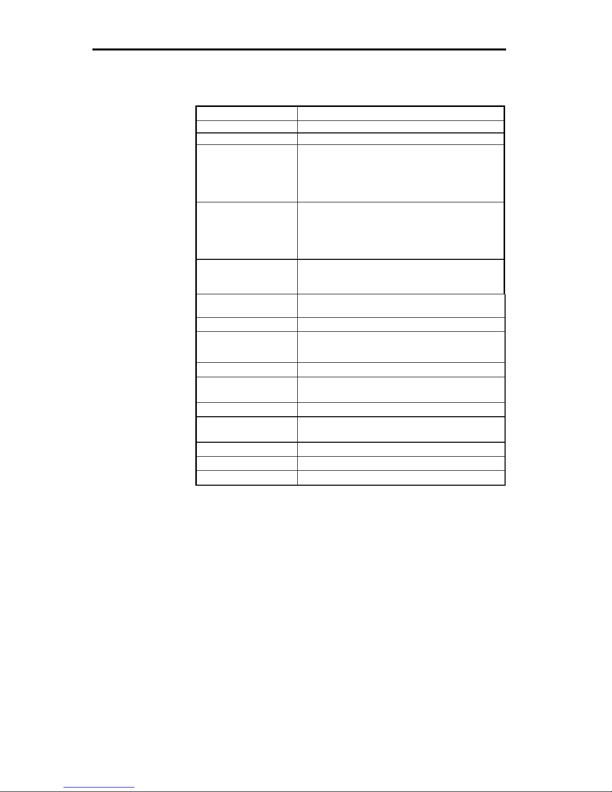
Specification
Digital inputs
Cable inputs: D1–4
IEC958, 75
Ω
Analogue inputs
Turntable pickup MM Nominal sensitivity is adjustable: 9mV, 8mV,
4mV or 2mV for 5cm/s @ 1kHz.
Input for full digital level, i.e. overload point:
47mV, 38mV, 19mV or 9.5mV @ 1kHz.
Cartridge load 47k
Ω // 100pF.
Turntable pickup MC Nominal sensitivity is adjustable: 600µV,
480µV, 240µV or 120µV for 5cm/s @ 1kHz.
Input for full digital level, i.e. overload point:
2.8mV, 2.4mV, 1.2mV or 600µV @ 1kHz.
Cartridge load 220
Ω // 10nF.
High-level flat inputs:
Radio, Video, Tape 1
and Tape 2
Inputs are separately adjustable. Input signal
for full digital level is: 2.5V, 2V, 1V or 500mV.
Input impedance 20k
Ω
Digital outputs
As input for digital input sources:
Internal conversion 44.1kHz ± 50ppm
Cable outputs: 1, 2
IEC958, 75
Ω
Analogue outputs
Tape outputs: 1, 2 Output voltage equal to input voltage
Analogue/Digital
conversion
1 stereo 16-bit Delta–Sigma converter running
with 64-times oversampling at 44.1kHz.
Distortion
<0.01% input to output up to digital full-scale .
Noise and hum
< –90dBr for digital or high-level analogue inputs.< –70dB MM input; <–60dB MC input.
Controls
Source, Copy, Display, Mute, Volume, Off
Dimensions
325 x ?? x 320mm, (12.9 x ??9 x 12.6")
Weight
?? kg (?? lb.)
Page 34

Help 34
562 User Guide
Help!
Standby point not lit
Check the following:
1. There is AC power connected to the socket on the rear of the 562
2. The power switch on the rear panel of the 562 is turned on
If the 562 will still not illuminate, check any fuses in your power supply
and the fuse in the inlet of the 562. If these are all intact, contact your
dealer.
Audible hiss at high volume settings
The input dynamic range of any recordings you have are at maximum 16
bit. The reason for this is that CD and other consumer sources use a 16
bit standard. The analogue sources you have cannot achieve this kind of
range. For comparison, analogue sources are likely to be of the order of:
• FM Radio, 13 bits
• Reel-reel tape, 13 bits
• Cassette tape, 12 bits
• LP, 11 bits.
Note that there may be a difference between the dynamic-range of the
source channel when it is operating, and the noise you hear in standby.
For example LP normally has lower noise when the stylus is not in the
groove; similarly tape will be quieter when it is stopped. CD may also be
quieter when it is stopped, producing so-called ‘digital silence’.
The 562 has a 16 bit capability from input to output on analogue sources.
When the volume is turned up high you may hear this dither as a hiss
when the sources are stopped. This hiss is lower than the background
noise of your recordings and is of no consequence.
Poor sound quality
Poor sound quality will usually result from one of the following:
• Driving an analogue input too hard. generally this will be accompanied
by a flashing of the Level light on the front panel. The solution is to
adjust the input sensitivity for that source in Gain. See page Error!
Bookmark not defined..
Hum on LP inputs
The turntable input is the most sensitive on the 562. It is fairly common for
installations to have problems with hum. The most common causes are:
• Tone-arm not connected to the technical ground of 562 as described
on page 25.
• Tone-arm connected to power ground in turntable. This connection is
not appropriate for 562 since the analogue input section of 562 is not
connected to its output (which is connected to the power ground).
• Magnetic pick-up. If you have another piece of equipment that incorpo-
rates a mains transformer too near the turntable or the left-hand-side
of 562 this may be the cause of hum
– particularly with MC cartridges.
Re-orient the equipment to see if this fixes the problem.
Hum on other inputs
There is no reason for 562 to produce hum on analogue inputs other than
LP. Check the source equipment. If 562 seems to be the cause of hum
consult your dealer.
Page 35

Help 35
562 User Guide
Communications not working between 562 and other
Meridian products.
If you have this problem check the connections carefully. Are you using a
B-lead or P-lead instead of a B1-lead?
Are you using a mix of 200 and 500 mode units?
Radio interference
NOTE 562 is a digital audio and computing device which has been de-
signed to very high standards of electromagnetic compatibility.
FCC WARNING: This equipment generates and can radiate radio frequency energy and if not installed and used correctly in accordance with
our instructions may cause interference to radio communications or radio
and television reception. It has been type-tested and complies with the
limits set out in Subpart J, Part 15 of FCC rules for a Class B computing
device. These limits are intended to provide reasonable protection against
such interference in home installations.
If this equipment does cause or suffer from interference to/from radio or
television reception then the following measures should be tried:
1. Reorient the receiving aerial (or antenna) or route the antenna cable of
the receiver as far as possible from the 562 and its cabling.
2. Ensure that the receiver uses well-screened antenna cable.
3. Relocate the receiver with respect to the 562.
4. Connect the receiver and this product to different AC outlets.
5. If the problem persists contact your dealer.
EEC This product has been designed to comply with the limits set out in
EN55013 and EN55020C.
REMEMBER to switch all units off before changing any connections.
Cleaning
When cleaning the 562 bear in mind that the front of the unit is plastic,
and the display panel and top surface are glass.
Disconnect the power cord before cleaning the unit.
Note Do not use abrasive cleaners on any part of the 562.
Maintenance & Service
The Meridian 500-Series of hi-fi components have been carefully designed to give years of untroubled service, and there are no user-serviceable parts inside the case, nor do the units require any form of maintenance.
In the unlikely event that your 562 fails to function correctly, it should be
returned, in its original packing, to your Meridian dealer. In case of difficulty, please write to:
In the UK:
Digital Gramophone & Wireless Ltd.
14 Clifton Road, Huntingdon,
Cambridgeshire, PE18 7EJ.
Page 36

Help 36
562 User Guide
Outside the UK: contact the importing agent for the territory. A list of
Meridian agents abroad is available from the above address.
No responsibility can be accepted for the 562 whilst in transit to the factory or an agent and customers are, therefore, advised to insure the unit.
In the USA and Canada, contact:
Meridian America Inc.,
3800 Camp Creek Parkway
Building 2400, Suite 112
Atlanta, GA 30331
Tel. (404) 344-7111
Fax (404) 346-7111
Guarantee
The Meridian 562 is guaranteed against defects in material and workmanship for 2 years from the date of purchase.
The guarantee is void if the 562 has been subjected to misuse, accident
or negligence, or has been in any way tampered with or modified without
the written authorisation of DGW Ltd.
Note that connecting anything other than the correct Network-Lead to the
socket marked 600 COMMS may cause damage to the 562 which will not
be covered by this guarantee. Attempted servicing by unauthorised people may invalidate this guarantee.
Labour and carriage charges are not covered unless by local agreement.
When seeking service under guarantee, proof of the date of purchase will
be required.
Outside the UK, local warranty liability is restricted to equipment pur-
chased within the territory. Our agents abroad are only under contractual
obligation to service under guarantee equipment sold through them. They
are entitled to make a non-refundable charge for any service carried out
on other equipment.
This guarantee does not limit your statutory rights within the United Kingdom.
Page 37

Index 37
562 User Guide
Index
600-Series, 5
A/D converter
input levels, 24
Acknowledgements, 3
Analogue to digital. see A/D converter
Background noise, 34
Balance
choosing delay, 18, 19, 20
resetting, 11
using control, 11
Cable
analogue audio, 25
for digital audio, 26
inputs, 22
Cartridge. see Turntable
Cassette. see recorder
Coax. see cable
Communication
making connections, 26
Config
choosing D6000, 18
display options, 18
how to get into, 15
how to use, 18
overview, 13
setting sources, 18
setting up outputs, 18
Connections
analogue, 25
audio, 25
Communications, 25, 26
digital, 25
digital audio, 25
general, 7
power, 25
to a digital recorder, 27
to an analogue recorder, 27
turntable, 25
Contents, 2
Customising
a full process, 16
balance, 13
displays, 13
finishing off, 23
how to, 15
making changes, 16
outputs, 13
overview, 13
using Config, 18
using Setup, 23
using Type, 16
with Config, 13
with D6000, 13
with Type, 13
D6000
setting in Config, 18
using Type, 16
Default settings, 13
Delay
in balance, 18, 19, 20
Demute. see Mute
Digital
connection, 25
Display
logos, 21
second volume, 10
setting in Config, 18
source and volume, 10
to change, 10
with D6000, 10
Dynamic range, 34
EPROM
version number, 10
Guarantee, 36
Hafler. see surround
Help!, 34
Hiss, 34
Hum
on flat inputs, 34
on LP input, 34
Input
changing for a source, 22, 23
choosing in Config, 22, 23
connections, 25
digital connections, 25
MC or MM levels, 14
overload, 31
setting levels in Setup, 24
understanding sensitivity, 31
voltage level overview, 14
Installation
customising, 6
general, 6
siting, 7
Types, 6
Introduction, 5
Level
light on front, 24
Logo, 21
LP sound, 31
Multiroom
via Type, 16
Mute
demuting, 10
Page 38

Index 38
562 User Guide
how to, 9
Noise, audible backgound, 34
None, a source, 18
Normal
how to get back to, 15
Operating
basics, 8
summary, 12
Optical
inputs, 22
Output
digital audio connections, 25
setting up in Config, 18
Overload
of inputs, 31
Pickup. see Turntable
Power switch, 8
Programming. see Customising
Radio interference, 35
Recorder
analogue, connecting, 27
digital, connecting, 27
Recording
choosing Type, 16
Remote control
using, 11
Repacking 601. see Unpacking
Restoring defaults, 13
Service
where to get, 35
Setup. see Customising
how to get into, 15
input levels, 24
inputs, 14
Level light, 24
using, 23
Sound quality poor, 34
Source
setting in Config, 18
Specifications, 33
Standby
display, 8
getting into, 8
to get out of, 8
Surround
using Type 6, 16
Switching on, 8
Tape recorder. see recorder
Turntable
getting the best out of it, 31
input MM or MC, 22
input sensitivity, 14
optimising the sound, 32
Type
how to get into, 15
list of, 16
overview, 13
Unpacking 601, 6
Version. see EPROM
Volume
display, 9
numbers, 9
Volume, adjusting, 9
Warranty, 36
Page 39

Notes 39
562 User Guide
Notes
Page 40

Notes 40
562 User Guide
 Loading...