

Meridian 5.24, 5.32 N3V Instructions Manual

1
5.24 and 5.32 N3V
CONDENSING GAS – FIRED
WALL MOUNTED
STAINLESS STEEL BOILER
Heating only or with external tank
and Solar System
INSTRUCTIONS FOR INSTALLATION
OPERATING AND MAINTENANCE
AUSTRALIAN VERSION
For Sales and Service contact;
AGENT
Automatic Heating Pty Ltd
51 Assembly Drive, PO Box 356
Tullamarine Vic 3043 Australia
Telephone: +61 3 9330 3300 Facsimile +61 3 8318 7319
Email: sales@automaticheating.com.au | www.automaticheating.com.au

2
WARNING
Before filling the heating system , new or existing, is necessary to check that it will be
clean and there will be not impurity and/or residual and then let in a suitable inhibitor

3
INDEX
INDEX.............................................................................................................................. 3
BOILER DIAGRAM AND LEGEND CONENSA 5.24 e 5.32 N3V .................................... 5
CHARACTERISTICS, DIMENSIONS AND TEMPLATES ............................................... 6
1 USER INSTRUCTIONS .................................................................................................... 7
1.1 General warnings....................................................................................................... 7
1.2 First start-up. ............................................................................................................. 8
1.3 Signals and diagnostics ........................................................................................... 10
1.5 Operating of the solar system .................................................................................. 11
1.5. CH pressure regulation ........................................................................................... 12
1.6 Periodical check-ups. ............................................................................................... 12
1.7 Antifreeze feature. ................................................................................................... 12
1.8 Definitive dismantling. .............................................................................................. 13
1.9 Problems, causes and solutions. ............................................................................ 13
2 INSTALLER INSTRUCTIONS ........................................................................................ 14
2.1 Boiler installation ..................................................................................................... 14
2.2 Installation ............................................................................................................... 15
2.3 Hydraulic connections .............................................................................................. 15
2.4 Condense drainage system. .................................................................................... 16
2.5 Gas connections. ..................................................................................................... 16
2.6 Electrical connections control board functioning and regulation .............................. 16
2.7 Thermoregulation devices and accessories. ............................................................ 19
2.8 Automatic high/low temperature circuit .................................................................... 21
2.9 Filling the CH circuit (for remote tank) ..................................................................... 22
2.10 Filling heating circuit ............................................................................................. 22
2.11 Filling the condense drainage system. ................................................................... 23
2.12 System start-up...................................................................................................... 23
2.13 The pump. ............................................................................................................. 23
2.14 Zone system .......................................................................................................... 24
2.15 Boiler safety valve. ................................................................................................. 24
2.16 Boiler draining. ....................................................................................................... 24
2.17 Safety valve tank ................................................................................................... 25
2.18 Boiler draining. ....................................................................................................... 25
2.19 Draught terminal positioning, wall outlet ................................................................ 25
2.20 Configuration type B23 open chamber and forced draft. ....................................... 26
2.21 Wall mounted coaxial air/flue ducts - type C13 ...................................................... 26
2.22 ROOF OUTLET AIR/FLUE DUCT TYPE C33 ....................................................... 27
2.23 Separate air inlet/flue outlet system. ...................................................................... 29
2.24 Chimney flue outet or tubing outlet duct type C53 – C83 ....................................... 30
2.25
Solar system functioning .................................................................................. 32

4
3 SERVICING INSTRUCTIONS ........................................................................................ 34
3.1 First start-up tests. ................................................................................................... 34
3.2 Settings (stand alone settings) ................................................................................ 34
3.3 Gas pressure regulation. ......................................................................................... 37
3.5 Boiler diagnostic ...................................................................................................... 40
3.6 Maintenance function ............................................................................................... 40
3.7 Adjustment of nominal heating power. ..................................................................... 40
3.9 Selection of flow temperature in heating mode. (not possible on cascade systems)
...................................................................................................................................... 41
3.10 Pump anti-block function ....................................................................................... 41
3.11 Heating anti-freeze function. .................................................................................. 41
3.12 Maintenance. ......................................................................................................... 41
3.11 Maintenance of the burner and heat exchanger .................................................... 42
3.14 Problems, causes and solutions. ........................................................................... 44
3.15 Warranty ................................................................................................................ 49

5
BOILER DIAGRAM AND LEGEND MERIDIAN 5.24 e 5.32 N3V
28
27
26
29
30
33
32
31
35
34
19 20
3 bar
22 23
24
25
5
8
9
10
7
6
3
4
2
1
16 1715
14
13
11
12
2118
1)Flue /air outlet ducts
2)Air combustion duct
3)Manual vent tap
4) Burner
5)Ionisation electrode
6)Expansion vessel
7)Safety thermostat
8)Flow temperature sensor
9)Fan
10)Differential pressure switch
11)Circulator
12)Three way valve
13)attack water gauge bulbous
14)by pass heating circuit
15)CH flow
16)Flow tank
17)Tank return
18)water fill
19)cool water inlet
20)safety valve
21)heating back
22)drainage tap
23)gas inlet
24)trap condense drainage
25)automatic air vent
26/gas valve
27)signal compensation silicone pipe
28)supply transformer 24V
29)wrinkled air inlet duct
30)Ignition electrode
31)Led burner
32)Ignitor
33)safety flue thermofuse
34)plug for compensation pipe
35)flue temperature sensor
36)function mode selector
39)Display
37)Sanitary temperature regulation
40)Manometer
38)heating temperature regulation
41)temperature boiler tank
36 37 38 39 40
41
Fig.1
Particular selector functions 36) with
meaning symbol
Spazzacamino
Reset
OFF
Estate
Inverno
6
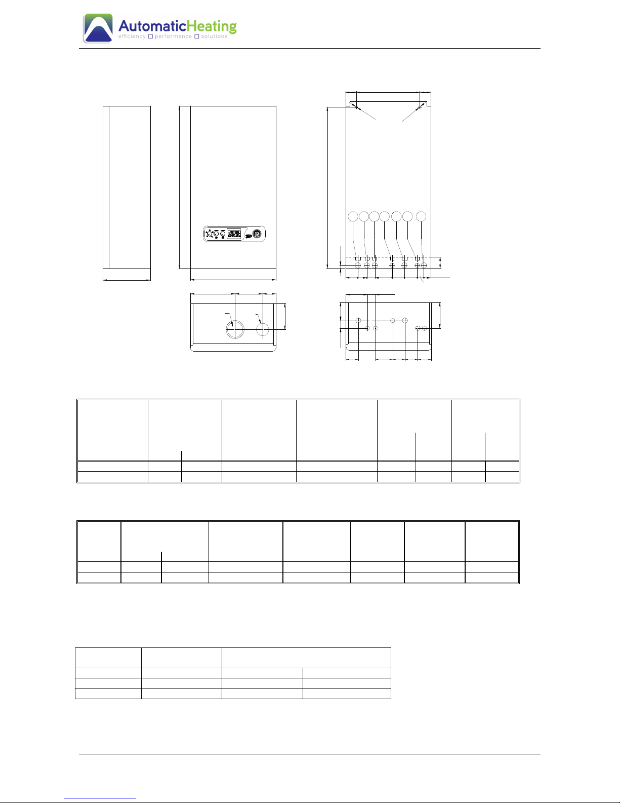
CHARACTERISTICS, DIMENSIONS AND TEMPLATES
7
6
5
4
32
845
850
1
68
68
Ø60/100
236
450
250
280
(mod.5.32)
B
137
69145
113
42
Ø80
40
65 6591
42
6548
65
16
91
135
71
.
36
60
35
Ø
1
2
335
vista frontale
58
Ø
1
2
58
(mod. 3.15 -
5.24)
1)CH flow ¾\“ 2)Flow tank 3/4 3)Flow tank 3/4 “ 4)Cool inlet
5)CH return 3/4“ 6)Gas inlet 1/2“ 7)Condense drain
MERIDIAN
N3V
HEAT INPUT
HEAT OUTPUT
80°C FLOW
60°C RETURN
HEAT OUTPUT
50°C FLOW
30°C RETURN
MIN HEAT
INPUT
MIN HEAT
OUTPUT
Nat
Gas
Propane
Gas
Nat
Gas
Propane
Gas
kW MJ/hr
5.24 26.6 96 23.4 27 5.5 - 5.0 -
5.32 33.3 120 29.4 33 6.7 9.0 6.0 7.9
Tab 1
INLET GAS
PRESSURE
FLUE
TEMPERATURE
FLUE GAS
VOLUME
MAX
WATER
VOLUME
EXPANSION
VESSEL
WEIGHT
DRY
Natural
Propane
°C
kg/hr l l kg
5.24 1.1 - 77 50.3 3.5 10 42
5.32 1.1 2.75 77 37.7 3.5 10 42
Tab 2
Boiler Water
Volume
Inlet Gas Pressure kPa
L
NATURAL
PROPANE
5.24 3.5 1.1 -
5.32 3.5 1.1 2.75

7
1 USER INSTRUCTIONS
1.1 General warnings.
This instruction Booklet constitutes an integral and essential part of the product.
Make sure that it is always left near the appliance. Please, read carefully the advice
and warnings contained in this section as they provide important indications on the
boiler use.
IMPORTANT: This boiler has been design to produce water for heating and sanitary
purposes at a temperature below boiling point at atmospheric pressure, in accordance with
its technical features of performance and its power. It is strictly forbidden to use the
equipment for other purposes.
The manufacturer cannot be held responsible for any damage caused by improper or
unreasonable uses.
This gas equipment shall be used following some fundamental requirements, such
as:
• do not touch the hot parts of the boiler, flue ducts, etc., which are overheated during
operation. Any contact with these parts may cause serious burns;
• do not spray water or any inflammable liquids;
• do not leave any object on the boiler;
• do not leave any container with inflammable liquids where the boiler is installed;
• do not carry out cleaning in the boiler room when it is in use (alcohol, gasoline, etc.);
• in case of gas smell do not turn on switches or any device which may generate sparks;
open all doors and windows so as to let air circulate; close the gas valve, above all the
main valve of the meter; call our Technical After-Sales Service Department.
Warning. The use of any component which is electrically supplied requires the close
observance of certain fundamental rules, such as:
• do not pull the wiring or leads;
• do not leave the apparatus exposed to atmospheric agents;
• do not touch the apparatus with parts of the body which are wet or damp and/or in bare
feet;
• do not allow any children to use the boiler nor any person who is not qualified with the
necessary technical ability and knowledge in the heating system sector.
Warning: Servicing shall be carried out only by authorised personnel.
The appliance is unsuitable for use as a pool heater.
Identification of functions enabled
This boiler can heat rooms and if required can heat a remote tank. If the hot sanitary water is not
produced by remote tank, selector 37 of fig. 1 is not available. When in doubt contact Automatic
Heating After-Sales Service Department.

8
1.2 First start-up.
Before the first start-up, please check that the system is properly filled with water and that
it has pressure 1 ÷ 1.3 bar, then proceed as follows:
• open the gas valve;
• turn the selector (36) on the only DHW function or on the DHW/CH function;
• Our remote control operation (Optional RC). When the selector is in winter position
and the RC is connected, the temperature potentiometers on the boiler control board
are excluded, and it will appear "EC" (External Control) written on the display. All the
regulations can be carried out by the RC.
• Operation without remote control. With the selector on the DHW position the CH
regulating potentiometer (38) is excluded and the temperature of the DHW is regulated
by the DHW potentiometer (37):with the selector on the DHW/CH position the CH
regulating potentiometer is enabled to regulate the temperature in the radiators (38),
and it also keeps the DHW potentiometer functioning. Turning it clockwise makes the
temperature increase, while turning anticlockwise it decreases.
From this moment the boiler is ready to operate automatically. A led (fig.4 pos.44) on the
control panel shows that the burner is on. When the CH or DHW water potentiometers are
turned, the display indicates the temperature chosen and at the same time LED’s (50) on
the display blink according to which potentiometer is operating.
External sensor (optional)
The external temperature sensor adjusts the temperature of the boiler according to the
external temperature. Adjustment involves the possibility of choosing from curves that go
from 0.5 to 6 with 0.1 steps. With advice from the installer or heat engineer who designed
the system, the curve that behaves as closely as possible to the behaviour required in the
apartment should be selected.
The curve is adjusted:
a) on the trimmer (41) if you have not purchased the remote control (optional) which
adjusts the curve by ± 5°C and can therefore be used to easily optimise thermal
comfort. The basic operating adjustment of the curve is effected by the
installer/support service
b) Using the remote control if present see the following steps:
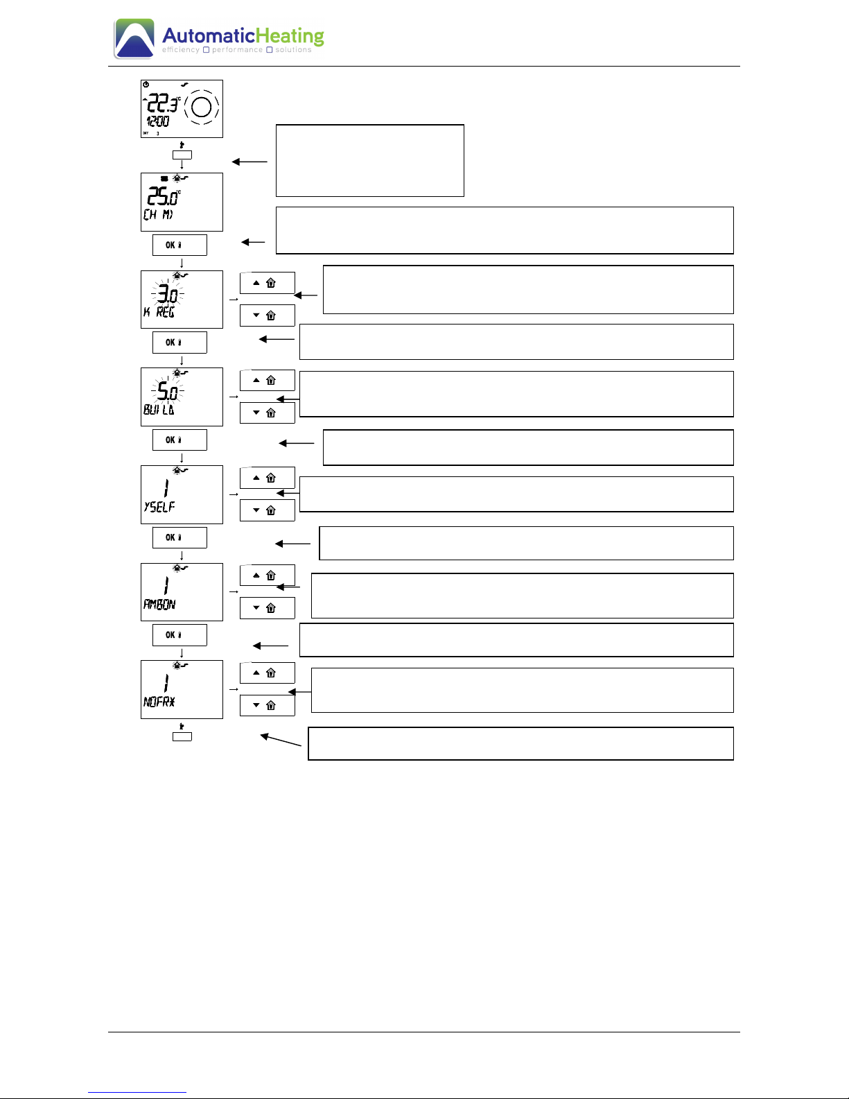
9
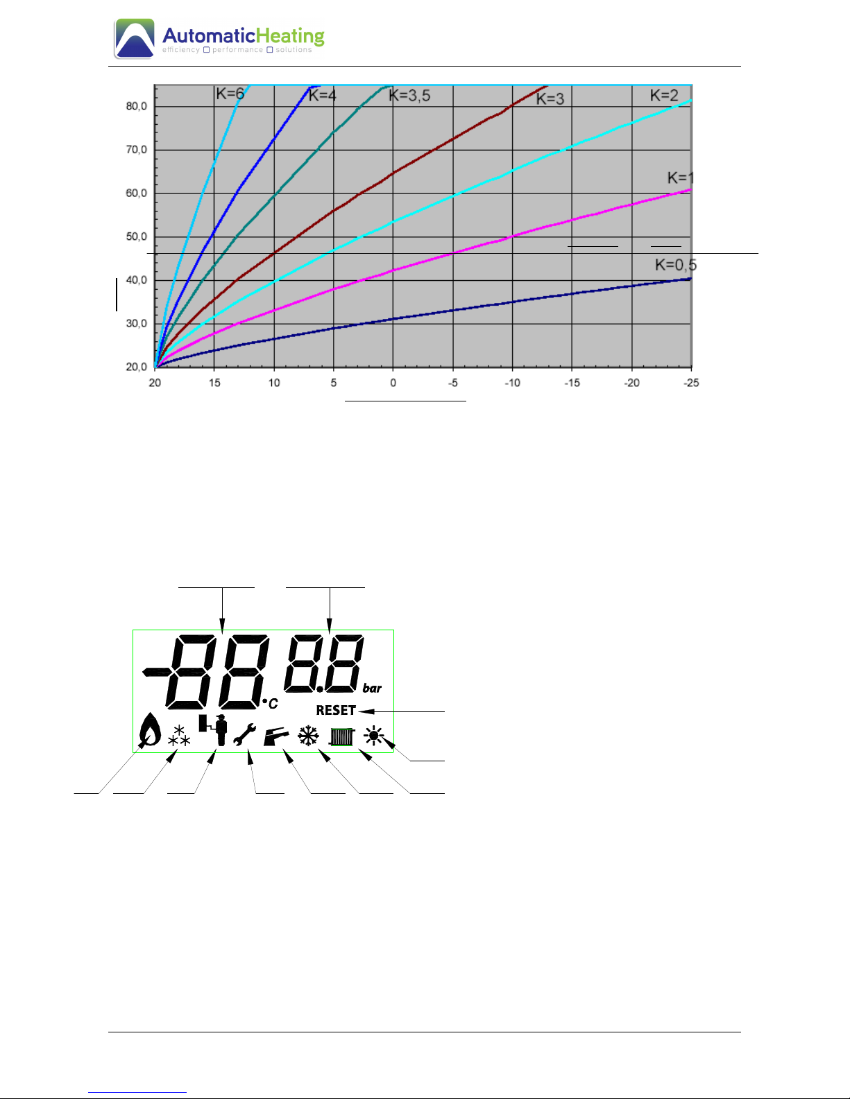
When using an external sensor, the flow temperature is automatically calculated according
to the external temperature and the K coefficient that has been set. If you are also set the
function YSELF the curve will be controlled and in case modified by algorithm inside of
remote control in order to ensure optimal comfort and maximum energy savings.
If you put in action the YSELF function also the AMBON function must be activated.
The AMBON function is integrated in the remote control.
51
12
9
12
18
0
3
6
PRESS THE BUTTON IP
MORE THAN 3 SECONDS TO
ENTER IN INFO MODALITY
PRESS THE BUTTON OK FOR MOVE FROM A WINDOW TO ANOTHER TILL
ARRIVE TO THE “K REG” FUNCTION
WITH UP E DOWN BUTTONS IT’S POSSIBLE TO CHANGE THE
EXTERNAL TEMPERATURE CURVE. REFER FUNCTIONING CURVES
FIG.3
PRESS THE BUTTON OK FOR MOVE FROM A WINDOW TO ANOTHER
BUILDING SIZE PARAMETER: WITH UP AND DOWN BUTTONS IT’S
POSSIBLE TO CHANGE THE VALUE. A high value is associated with
buiding/heating system with high thermal inertia
PRESS OK BUTTON TO MOVE AT FOLLOWING WINDOW
PRESS OK BUTTON TO MOVE AT FOLLOWING WINDOW
AMBON
. WITH UP AND DOWN BUTTONS IT’S POSSIBLE TO CHOOSE
ENABLE 1 O DISABLING 0
YSELF
. WITH UP AND DOWN BUTTONS IT’S POSSIBLE TO CHOOSE
ENABLE
1 O DISAB
LING 0
PRESS IP BUTTON TO EXIT FROM THE WINDOW INFO
ENABLE ANTIFREEZE HOUSE FUNCTION. WITH UP AND DOWN
BUTTONS IT’S POSSIBLE TO CHOOSE ENABLE 1 O DISABLING 0
PRESS THE BUTTON OK FOR MOVE FROM A WINDOW TO ANOTHER
10
.
N.B.: in systems with zones with different temperatures, the factor available with the low
temperature room thermostat closed goes from 0.5 to 6 but the supply temperature is
limited to 45°C whereas with a high temperature room thermostat request, it goes
from 2.5 to 6 with a maximum temperature of 85°C.
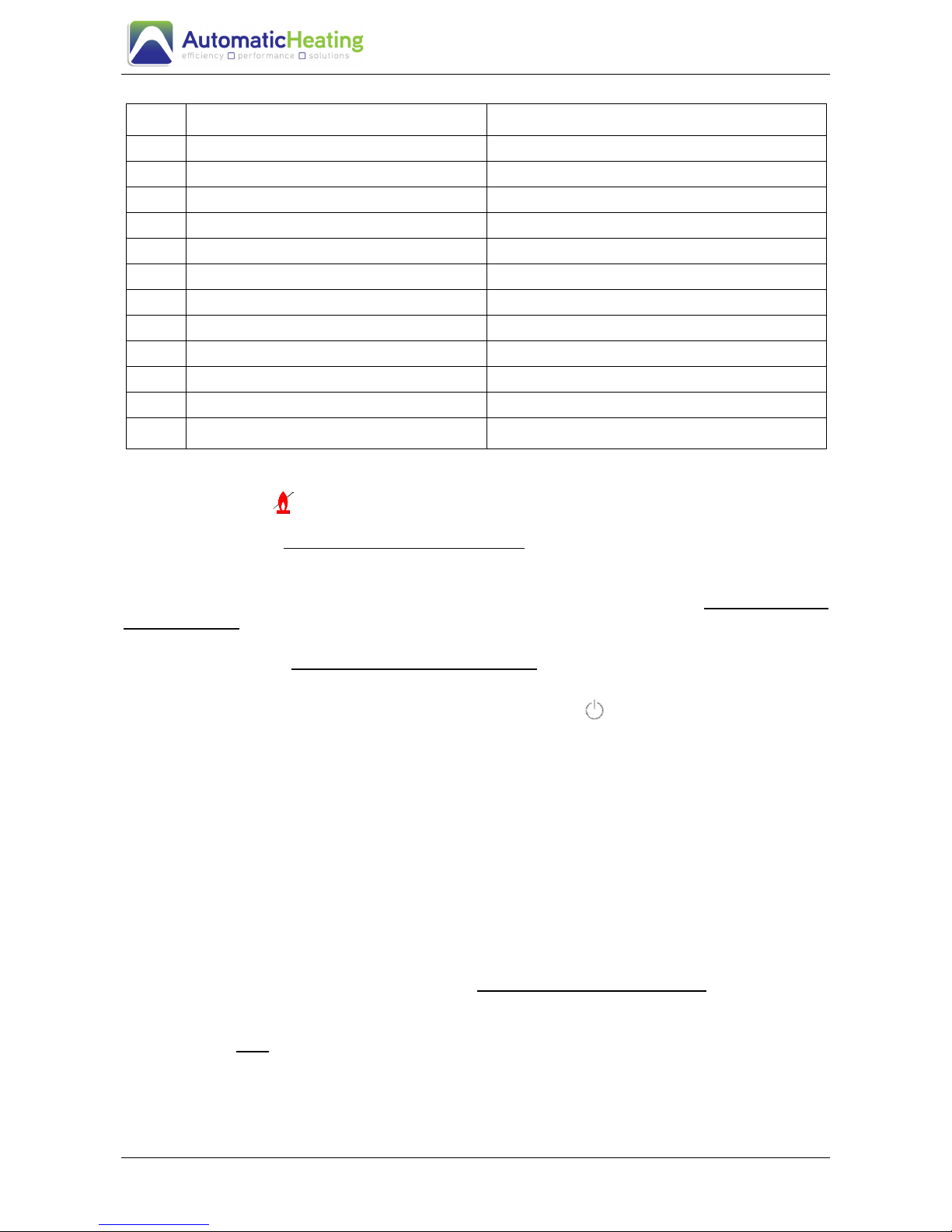
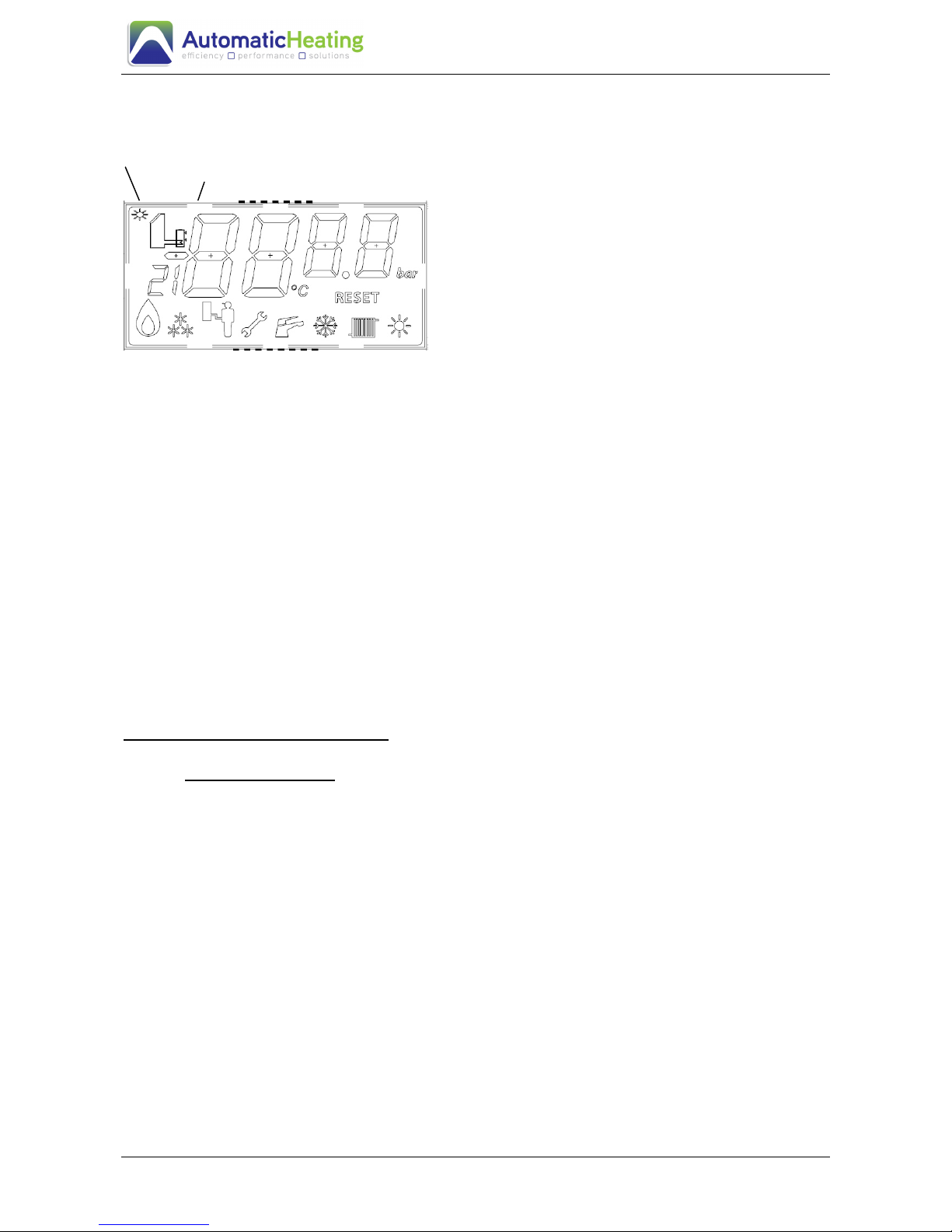
1.3 Signals and diagnostics
The boiler display is a complete system
with simple, intuitive information. An
explanation follows:
Key:
44) Burner start-up
45) Activation of anti-freeze function
46) Activation of service function (for
support service only)
47) Request for intervention/ resetting
48) Sanitary hot water request (if tank
present)
49) Selector switch on “Winter”
50) Heating request
51) Selector on “Summer”
52) “Reset” request
53) Used only for “Service”
54) Temperature reading/Fault code
During normal operating, the digits in 54) indicate the flow temperature value.
During normal operating and in STAND-BY, the flow temperature is also displayed in
large digits. The small digits are used by the installer or the maintenance technician for the
menus.
If there is a fault, the fault code is displayed in flashing mode in large digits with the
spanner symbol.
External temperature
Bolier Temperatur
Fig. 3
Cutting at 45°C at low temperature
464544 4847 49 50
51
53
54
52
11
Table 4
code fault Type of block
F1 No start-up or no flame detected Manual resetting is required
F2 Safety thermostat intervenes Manual resetting is required
F5 Faulty supply sensor It automatically resets if fault disappears
F7 Fault on flue gas sensor resistance Fixed with automatic reset – signaling for 24 hours
F8 Faulty external probe It automatically resets if fault disappears
F 10 Lack of water circulation on primary It automatically resets if fault disappears
F11 Hydraulic pressure <0,5 bar into heat exchanger It automatically resets if
F12 Faulty tank probe It automatically resets if fault disappears
F 16 Faulty fan It automatically resets if fault disappears
F26 Micro pressure water pasted It automatically reset if fault disappears
F 30 Faulty solar collector probe Maintenance technician is required
F 35 Faulty external tank
Solar system operates but the maintenance technician is
required
The boiler codes, 1 and 2, can be reset by the user by selecting selector 39) in Fig. 1 in
the reset position
If the block persists, contact the Sile Service Centre.
A block with 10 code can be caused by a lack of water in the system, or from the
circulating pump blocked or faulty. In The first case check that the system load pressure
on the boiler pressure gauge is approximately 1÷1.3 bar; in the second contact the Sile
Service Centre
For all remaining block codes that do not reset even after switching off the boiler and then
switching it on again, contact the Sile Service Centre.
1.4 Boiler shutdown.
To shut down the boiler turn the selector to the position off and turn the gas valve off. If
the boiler is not used for long periods of time, always close the main gas supply tap and
turn off the main power supply switch. In this mode antifreeze system remains active. For
a complete turn off the power supply to disconnect from the outside boiler.
1.5 Operating of the solar system
(to be activated only if the Solar System 2 sensor kit has been installed)
The solar function can be activated in the summer and winter to integrate the sanitary hot
water. It is activated using parameter 4 whose configuration mode is described in
paragraph 3.2
If you only wish the solar mode to be activated, normally in the summer, you can select
one of these configurations. Remember that parameter P4 must always be activated by
selecting value 1 :
1. status selector (39 Fig. 5) = SUMMER or with status selector = OFF;
2. heating set point selector on minimum;
The board only works in solar mode.
In the solar only mode, any external burner start-up request (sanitary request) is
deactivated whereas the anti-legionella and anti-freeze functions remain active.
In the “solar only” mode, the solar panel icon and collector temperature are shown on the
display
12
N.B.: do not activate the solar system if the optional 2 sensor kit has not been
installed because this may cause the system to malfunction and you may
have to call the service centre to resume boiler operating
1
2
Display in solar mode:
- When the solar function is activated, an
icon lights up indicating the solar system
- For 10 s after activation of the solar pump,
the temperature of the collector sensor is
displayed in large digits and the temperature of
the tank solar sensor (sanitary sensor) in small
digits.
The solar system operates when the flat collector temperature is higher than the solar tank
temperature as set in parameter 5 which defines the temperature differential between the
collector and the boiler. When exceeded, the solar system circulator comes on. This
parameter is adjusted as explained in paragraph 3.2.
If the differential is very low, between 5 and 10°C, the circulator will come on frequently to
disperse the small amount of heat that has accumulated in the panels. With a differential of
between 10 and 15°C, the circulator is activated less frequently because more time is
needed to recreate the difference in temperature between the two devices. Even higher
differentials should be avoided in the winter when solar radiation is limited and large
differences in temperature are difficult to obtain. We recommend a differential of
approximately 10-15°C which is a good compromise for the entire year. If this way, the
setting made by your authorised installer will not need adjusting.
1.5. CH pressure regulation
Periodically check that the pressure of the heating system is about 1÷1.3 bar; if pressure is
below 1 bar, when the boiler is cool, it is to be restored by cock placed in the boiler lower
part.
After the operation close the block
If pressure reaches 3.0 bar, it may activate the safety valve (fig. 1 pos. 20). In this case,
call our After-Sales Service. Please, do the same if pressure decreases frequently.
1.6 Periodical check-ups.
At the end of every heating period the boiler and its components, the external air duct (if
present), the flue pipes and the condense drainage system are to be inspected by our
authorised service centre in order to guarantee both the apparatus efficiency and the
proper systems operations.
Careful maintenance is always a good safety and money saving measure.
1.7 Antifreeze feature.
The boiler is equipped with a standard antifreeze feature which activates the pump and the
burner when the boiler temperature falls below 8°C and 6°C. It can be equipped with an
optional DHW circuit antifreeze device. The antifreeze feature is guaranteed if the boiler is
perfectly working, if it is not locked and it is electrically operated with the selector on the
DHW or DHW/CH position. Before a long absence, please check that the system is
completely emptied.
Fig. 10
13
1.8 Definitive dismantling.
In the event of the boiler definitive dismantling, it is to be performed by qualified personnel.
Make sure that also the electrical, hydraulic and fuel supplies are disconnected
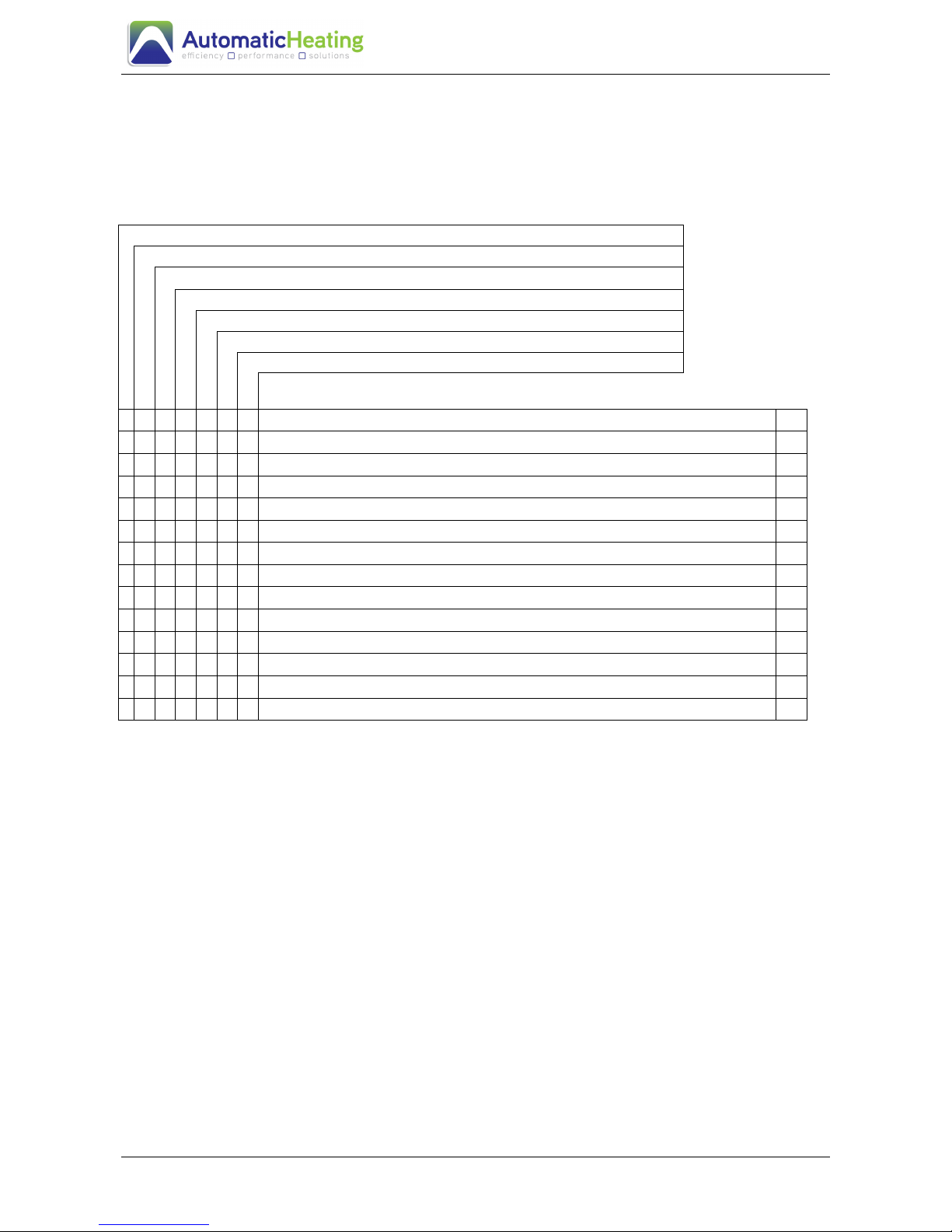
1.9 Problems, causes and solutions.
The burner ignites but immediately locks out (code 1)
The burner does not ignite
The pump is noisy
⇐ PROBLEMS
The DHW is not very hot
The heating is not sufficient
Error code 10 on the display
CAUSES
Error code 1/2/5/6/7/8/12/16 on the display
SOLUTIONS
⇓⇓⇓⇓ ⇓⇓⇓⇓
•
Air in the gas circuit 1
•
Gas supply suspension or large reduction in the circuit 2
•
The boiler is blocked 3
•
•
The selector is not set correctly 4
•
•
The CH potentiometer is set on a too low temperature 5
•
•
The room thermostat is off 6
•
•
The room thermostat is set on a too low temperature 7
• •
• •
Not enough water in the system 8
•
•
Air in the system 9
•
The DHW selector is set on a too low temperature 10
•
The cold water temperature is too low 11
•
Too large water drawings 11
•
Continuous hot water drawings 12
•
• • •
Other problems 14
Table 4
SOLUTIONS
1) Wait for about 10 sec., then repeat ignition operations.
2) Turn off the gas tap and wait until gas supply returns before igniting.
3) Wait for 10 sec., then reset the system and turn selector 39) fig.1to correct position
4) Turn the selector (39 fig.1) to the correct position.
5) Set the CH regulation potentiometer (41 fig. 1) to 75°C.
6) Set the room thermostat to a higher temperature.
7) See point 6.
8) Add water using the heat system loading tap; remove air from the system(23 fig.1). De-aerate the
system. Do not exceed 1 bar pressure indicated on the water gauge (43 fig.1). If pressure should
decrease again, request service from our authorised service centre or from professionally qualified
personnel to remove air from the system or to eliminate leakage.
9) See point 8.
10) Turn the DHW selector clockwise to a higher temperature.
11) The water drawing is too high, decrease it.
12) Wait for the DHW output to stop. Consider either solutions
13) Consult our authorised service centre or professionally qualified personnel

14
2 INSTALLER INSTRUCTIONS
2.1 Boiler installation
2.1.1 General rules
The boiler installation is intended to be fixed and it must be carried out by professionally
qualified staff, according to the actual national and local law, following all the instructions
and rules contained in this manual. The boiler shall be installed in a room free of corrosive
steam.
After unpacking the boiler, ensure the integrity of the content: in doubt, do not use the
apparatus and refer to the supplier. Packaging components (carton, foam, plastic bags,
etc.) are potential hazards and should not be left within the reach of children.
In case of installation inside or between pieces of furniture, let sufficient space to carry out
standard maintenance; we would suggest to leave a 3 cm interspace between the boiler
case and the wall of the piece of furniture.
The boiler has been designed to produce hot water at a temperature below boiling point at
atmospheric pressure. It must be connected to a CH system which is compatible with its
power and technical features. It is strictly forbidden to use the equipment for other
purposes.
Any other use is improper and therefore dangerous. The manufacturer cannot be held
responsible for damages caused by improper or unreasonable use.
In the event of irregularities, defects or malfunctioning, deactivate the boiler and contact
the Sile Service Centre. They will provide original spare parts and will settle the boiler.
Only professionally qualified personnel are allowed to overhaul and repair the boiler. If the
above mentioned rules are not respected, we will decline any responsibility and will not
grant the validity of the warranty.
Before installing the boiler:
• Check and washes all system pipes carefully in order to remove any impurities
and residual substances which could cause malfunction of heater exchanger
primary and secondary;
• Carry out the application of sludge blanket filter in the heating circuit;
• Introduce suitable inhibitor for the preservation of possible residual suspended
matters
Check the boiler fuel gas supply: compare the writing on the packaging and the technical
characteristics plate.
In case the appliance fails to operate correctly after all checks have been carried out, refer
to the authorised service provider in your area.
2.1.2. Installation room
The boiler can be installed in any type of room, provided that:
- the requirements of Gas Code AS5601 are observed.
- it is protected against freeze
- that the flue ducts can be installed adequately.

15
Clearances shall provide provision for service access and protection from combustible
surfaces. Minimum clearances from combustible surfaces shall be 50mm at sides, 300mm
from top and 300mm from bottom.
ENSURE THAT THE AIR ENTRY IS NOT OBSTRUCTED BY ADJACENT CABINETS
OR OTHER STRUCTURES.
2.2 Installation
If our accessories are used to install the boiler, read the instructions enclosed carefully.
After choosing the suitable position to install the boiler, fit the installation template (see fig.
2). It must be oriented perpendicularly by means of a spirit or a plumb line. The template
shows the two holes which serve to fasten the boiler to the wall. They are to be drilled with
a ∅ 12 mm drill bit. Insert the supplied dowels and ensure that the hooks are fit. Mark also
the position of the hydraulic and gas connections holes on the wall. The supplied dowel
can ensure a firm hold only if inserted properly. In the event that walls do not provide the
apparatus with a steady support, take the adequate countermeasures.
2.3 Hydraulic connections
The hydraulic connections must be performed in a rational manner by following the
indications of the boiler template (fig. 2). Optional is provided the kit 10 SILE including all
the compression fittings can be used, supplied on request. The boiler safety valve drain
must conduct to a secure draining tube. In absence of this tube, the possible intervention
of the safety valve may cause flooding. We cannot be held responsible for any damage
caused by neglecting to apply this technical precaution.
The boiler can work only in two following modes:
a) only heating mode
b) heating and sanitary through remote tank
That change are the following aspects:
a) heating mode: two connections 2) and 3) (fig.1) must be plugged with two plugs packed
inside the instructions bag. So you can close two connections to possible remote tank and
the boiler working only with heating circuit. Now must inhibit the sanitary probe (41 fig. 1)
functioning. This carries out on PCB working. See table relatives Dip-Switches positions on
PCB in the chapter 2.6 of this manual. Dip-Switch 6 must be moved to ON; so the
temperature probe is defused and there not will be malfunctioning for the not wanted
sanitary activation.
b) Heating and sanitary mode combined doesn’t occur to do anything because the boiler is
prepared in this mode so by the manufactory. We remember that the sanitary probe 41) fig.
1 must be put on the pocket tank to activate the heating tank. Don’t use the eventual
thermostat tank.
 Loading...