

Page 1
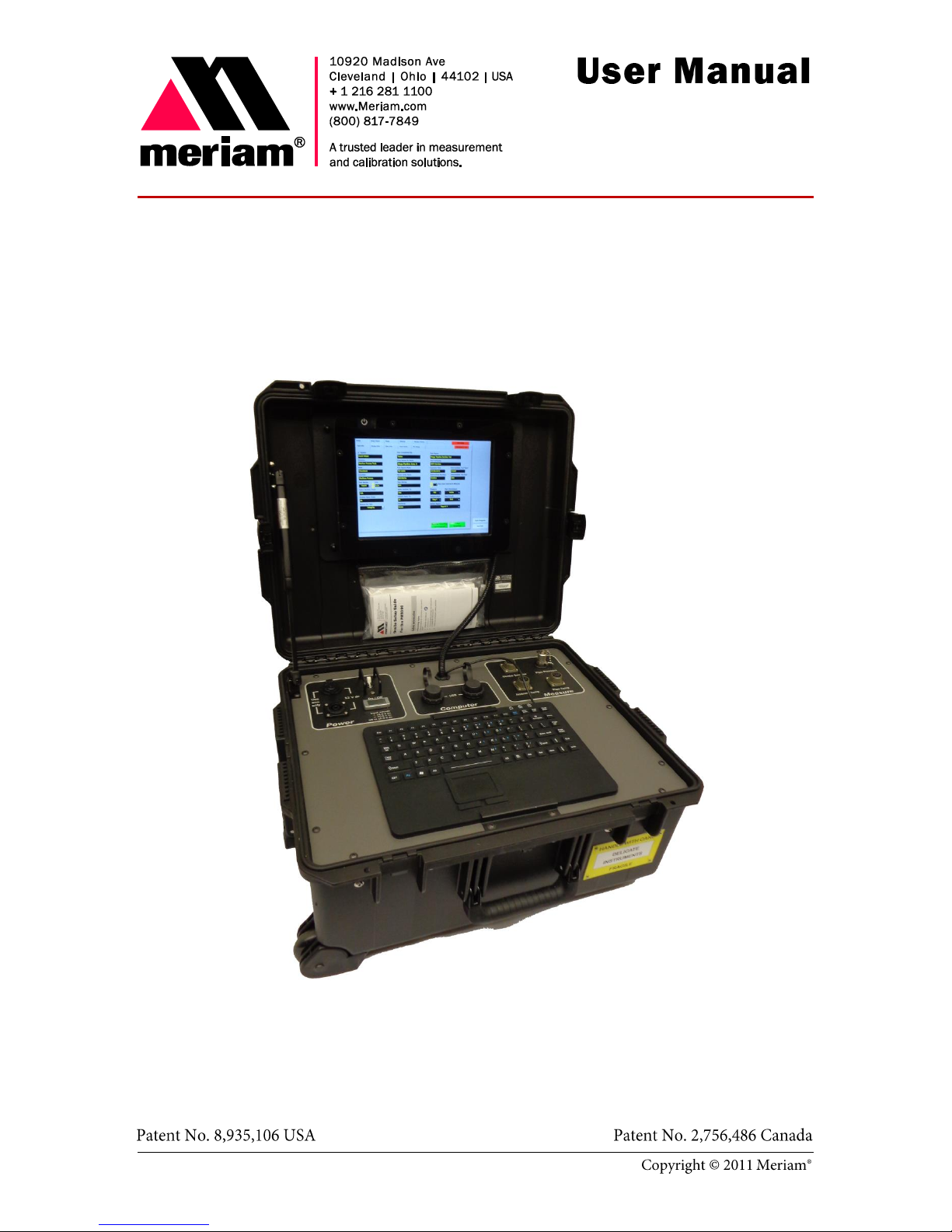
The PIT5000: Pipeline Integrity Tester
A Pipeline Hydrostatic Testing Device
Page 2
Introductory information
Disclaimer
Copyright
Notification Statements
Page 3

Notification Statements (continued)
Voids the computer warranty
Patent statement
Trademark statements
Patent and trademark information
Page 4
Safety Information
Preventing injury
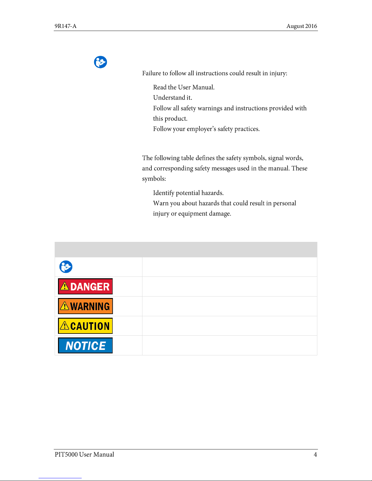
Safety Symbols
Safety Symbols
Explaining the symbols
This is the Read Instruction Manual symbol. This symbol
indicates that you must read the instruction manual.
Indicates a potentially hazardous situation which, if not avoided,
will result in death or serious injury.
Indicates a potentially hazardous situation which, if not avoided,
could result in death or serious injury.
Indicates a potentially hazardous situation which, if not avoided,
could result in minor or moderate injury.
Indicates information essential for proper product installation,
operation or maintenance.
Safety Symbols
Page 5
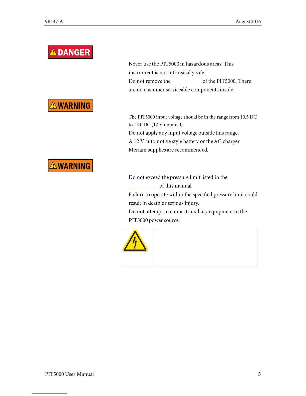
For your safety
Fire and/or explosion hazard
Control Panel
Power connections: DC and AC
Pressure limits and power issues
Specifications
Hazardous voltage inside.
Risk of electric shock or burn.
The control panel should only be removed by
authorized electrical technicians.
Page 6

Protect the PIT5000
Protect the PIT5000
Do not substitute parts
Page 7

Contents
A Pipeline Hydrostatic Testing Device ..............1
Introductory information ..................................2
Notification Statements ...................... 2
Notification Statements (continued) .. 3
Patent and trademark information .... 3
Safety Information .............................. 4
Safety Symbols .................................... 4
For your safety ..................................... 5
Protect the PIT5000 ............................ 6
Contents .............................................. 7
Meriam Contact Information .............. 8
Glossary ............................................... 9
Receiving, unpacking, and setting up the
PIT5000 ......................................................... 11
Add Note button ............................... 39
End Test button ................................ 40
Strip Chart tab .................................. 41
Strip Chart tab (continued) .............. 42
Data tab ............................................ 43
Details tab ......................................... 44
Details tab (reset, calibration, paths)
........................................................... 45
Details tab (do not delete these files)
........................................................... 46
Stroke Count tab .............................. 47
Stroke Count tab (continued) .......... 48
Stroke Count tab (continued) .......... 49
Stroke Count tab (continued) .......... 50
Shut down and disconnect .............. 51
Receiving and unpacking ................. 11
Hardware ....................................................... 12
Recommended power connections . 12
Temporary power connections ......... 13
Connecting the 12 V battery ............. 14
Computer mounting panel ................ 15
Control panel ..................................... 16
Software ........................................................ 23
First—Check the computer’s time .... 23
Second—zero the pressure ............... 25
Flexibility in the PIT5000 application
............................................................ 25
The main tabs in the application...... 25
Setup tab ........................................... 26
Report 2—the enhanced report ........ 35
Appendices ................................................... 52
Returning for repair or calibration .. 52
Troubleshooting Guide ..................... 53
Specifications ................................... 55
Specifications (continued) ............... 56
Part numbers .................................... 57
Data Panel ......................................... 36
Data Panel (continued) ..................... 37
Data Panel (Continued)..................... 38
Page 8
Meriam Contact Information
Meriam
Address
Meriam
10920 Madison Avenue
Cleveland | Ohio | 44102
USA
Telephone
US customers: (800) 817-7849
International customers: + 1 216 281 1100
Fax
US customers: + 1 216 281 0228
International customers: + 1 216 281 0228
E-mail addresses
Departments
E-mail addresses
Return Material Authorization /
Service & Repair Department
returnforms@meriam.com
Sales
sales@meriam.com
Website
www.Meriam.com
Local Meriam Representatives
Find a local Meriam
representative
Use this link to help you find Meriam representative on this
world map: REP LOCATOR.
Or, you may use this full website address to go to the same
location: http://www.meriam.com/representatives-map/
Page 9
Glossary
Words and phrases
Definitions
12 V car adapter cable
Also known as a cigarette lighter adapter. This is an optional cable
with DC-to-DC sockets.
Autoscale Graph
The Autoscale function automatically rescales the axes of the
currently selected graph based on the data it receives.
By default, autoscaling is always on.
Button or key
A button always refers to an area on the screen that you can
click to select functionality.
A key always refers to hardware push buttons on the keyboard
that you can press.
Control Panel
The Control Panel is located in the bottom of the carrying case. It
has the keyboard and these labeled areas: Power, Computer, and
Measure.
Data Panel
The Data Panel displays in the PIT5000 application on the right
side in all tabs. The panel displays different information including
flashing red alarms and the following four buttons: Start Program,
Begin Test, End Test, and Add Notes.
Digital Counter
A digital I/O device that provides 5 volts to the stroke counter and
converts the stroke count to a digital signal to the computer via
USB.
Dry contact set
The contacts in a Dry contact set do not have electrical power on
them. The dry contacts are for the (non-supplied) pump stroke
counter.
Edit box
Edit boxes (also known as fields) are for you to enter your data.
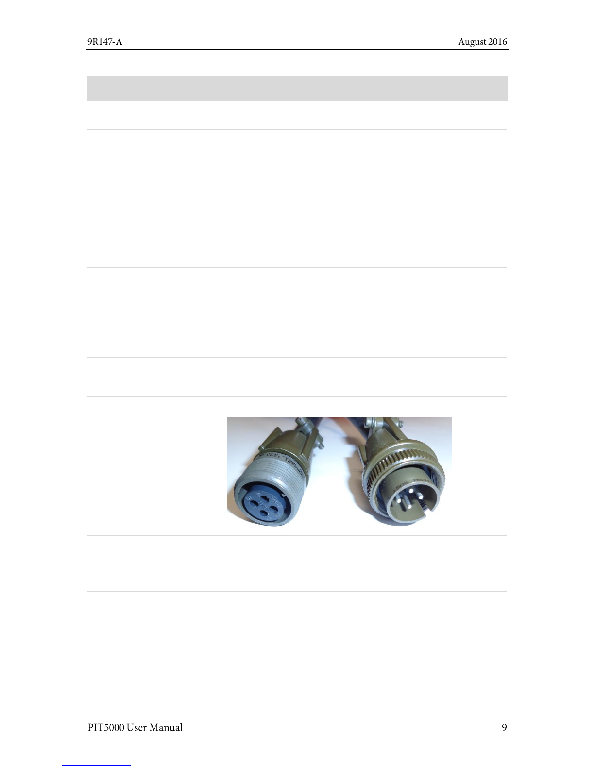
M12 connectors (M & F)
Male NPT
NPT is an abbreviation of National Pipe Thread (Tapered). This is a
standard male tapered pipe thread.
PIT5000
PIT is an acronym for Pipeline Integrity Tester.
P Leak Pressure
P Leak Pressure refers to Preliminary Leak Test Pressure. Some
customers perform a 15-minute leak test before going to higher
pressures.
Pressure
Pipe
You may see different ways of expressing these concepts in
printed material, on the PIT5000, and in the software. The most
common are:
Press
P Leak and PLeak
PTest
Page 10

Words and phrases
Definitions
PTest Instrument Pressure
PTest is an abbreviation of the words Pressure Test.
Instrument Pressure refers to the pressure of the PIT5000
device.
Quick-test connection
The Quick-test connection is located on the Control Panel in the
Measure pane.
RTD
RTD is an abbreviation of Resistance Temperature Detectors.
Strip Chart
Strip Chart is a tab in the PIT5000 application that displays a live
plot of pipe pressure (Press), ambient temperature (T-Amb) and
pipe temperature (T-Pipe) versus time in order to record the
hydrostatic test and its duration.
Stroke Count versus
Stroke Counter
Stroke Count refers to number of recorded pump strokes.
Stroke Counter refers to the digital counter that records pump
strokes. It is connected to the pump using the Stroke Counter
cable.
Temperature
Ambient
You may see different ways of expressing these concepts in
printed material, on the PIT5000, and in the software. The most
common are:
Tambient
T ambient
T-Amb
T Amb
Ambient Temp
Temperature
Pipeline
You may see different ways of expressing these concepts in
printed material, on the PIT5000, and in the software. The most
common are:
Pipeline Temp
Pipe Temperature
Pipe temp
T
T-Pipe or T-pipe
T Pipe
T
pipe
V dc
Volts direct current.
V ac
Volts alternating current.
Page 11
Receiving, unpacking, and setting up the PIT5000
Receiving the PIT5000
Unpacking the PIT5000
Don’t lose any of the components
a small 316SS adaptor fitting
Gear Kit
Receiving and unpacking
Page 12
Hardware
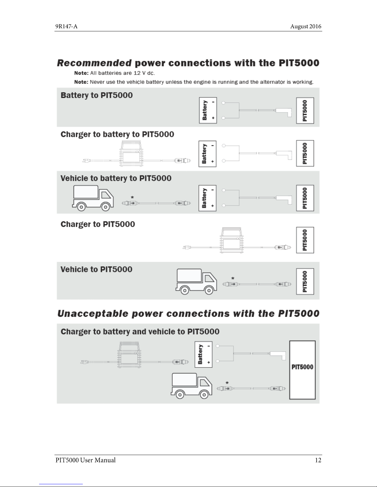
Recommended power connections
Page 13
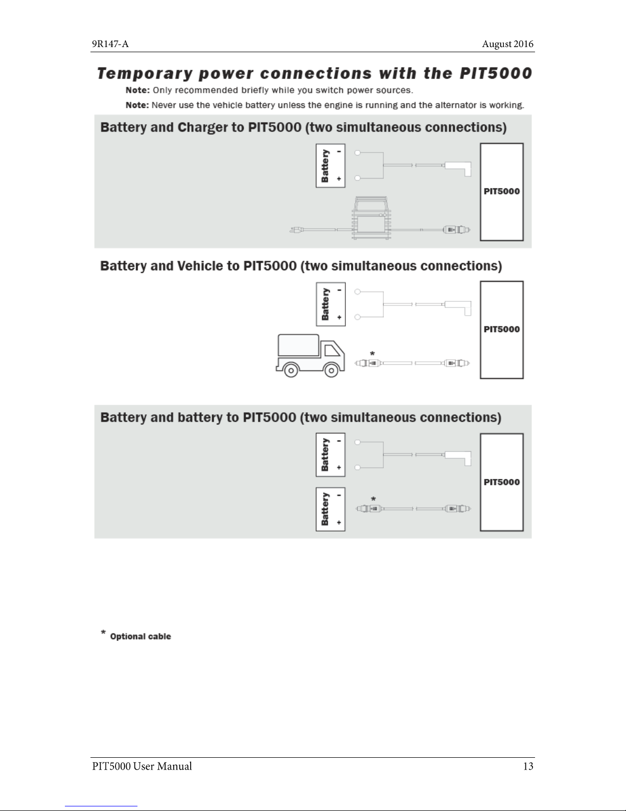
Temporary power connections
Page 14
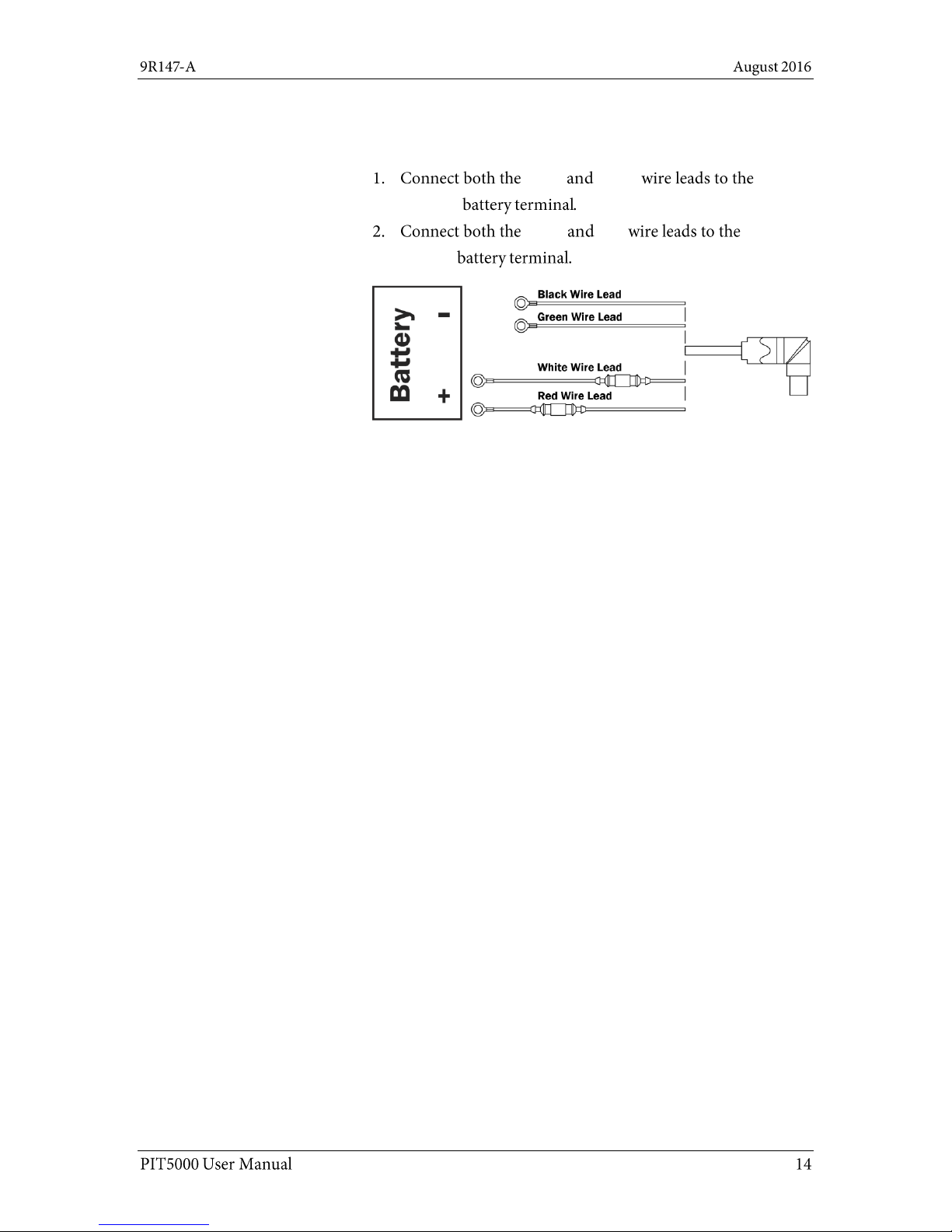
Connecting the 12 V battery
Four wires to two battery lugs
Black Green
negative
White Red
positive
Page 15
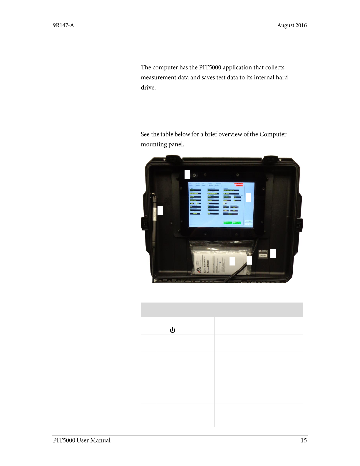
Computer mounting panel
The computer
Note: The computer has an internal battery but it is
normally powered by an external 12 V dc source.
Computer mounting panel
Computer mounting panel description
No.
Item
Description
1.
Power On button
The On / Off button is behind the
Plexiglas panel.
2.
Computer
Windows 10,
PIT5000 Application
3.
Nameplate
PIT5000 serial number, Meriam
address, power.
4.
Computer power
and USB cables
For the computer.
5.
Documentation
pouch
Onsite Setup Guide and NIST
Certificates.
6.
Lift support
This minimizes the risk caused
by an accidental closure. It
controls the closure speed.
1 2 3 4 5
6
Page 16
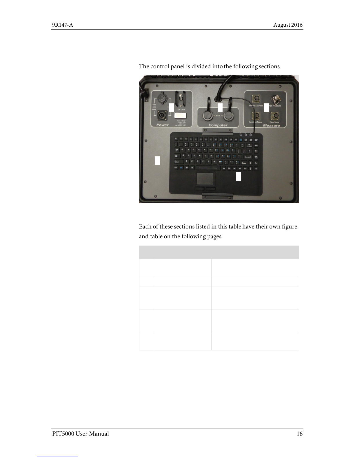
Control panel
Control Panel
Control Panel description
No.
Item
Description
1.
Power pane
Two power connections, toggle
switch, LCD display
2.
Computer pane
Two auxiliary USB ports
3.
Measure pane
Stroke counter connection,
connections for pressure and
temperature.
4.
Control panel plate
The control panel should only be
removed by authorized electrical
technicians.
5.
Keyboard
A waterproof and contaminateproof keyboard and touchpad.
1 2 3
4
5
Page 17
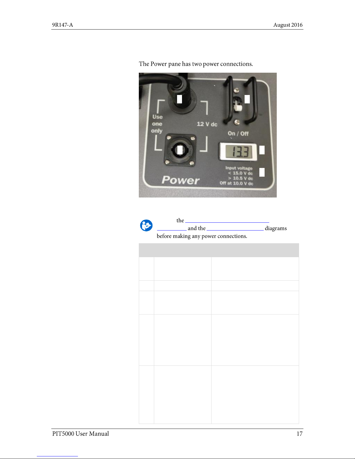
1. Power pane
Power pane
Power pane description
Review Recommended and unacceptable
connections Temporary connections
No.
Item
Description
1.
12 V car adapter
For connecting either the AC to
DC charger or the optional DC to
DC cable.
2.
Toggle switch
Move switch to turn On / Off.
3.
12 V dc power
locking cable
The locking cable is the preferred
battery connection. It provides
less energy loss.
4.
LCD display
Digital battery voltage indicator.
Note: If two batteries are
connected using both 12 V dc
connections on the Control
Panel, then this display averages
the voltage. This averaging
makes the LCD unreliable.
5.
Input voltage list
It reminds you of three levels:
1. The highest allowable is
15.0 V.
2. An audible alarm sounds
when the battery voltage
goes below 10.5 V.
3. The PIT5000 shuts off at
10.0 V.
1 2 3 4 5
Page 18
2. Power pane (continued)
Power source
On
Note: Fuses provide protection against an electrical
short.
AC power and the charger status
Review the Recommended and unacceptable
connections and the Temporary connections diagrams
before making any power connections.
DC power
Standard:
Optional:
Note: It can be used to power the PIT5000 anywhere a
compatible 12 V dc car adapter is available. This can be
especially useful when hydrostatic tests run longer than
anticipated and the battery level gets low.
Page 19

3. Computer pane
Computer pane
Measure pane
1 2 3
4
4. Measure pane
Page 20

4. Measure pane (continued)
1 – Optional: Connect the Stroke Counter cable
to the Measure pane
Measure
Stroke Counter
Note: The PIT5000 has a digital counter that is equipped
to supply power and count the strokes made by highpressure, plunger pumps during pressurization of the
pipe section under test and the subsequent pressure
test.
2 - Pressure hose
Measure
3 & 4 - Connect the RTD cables to the Measure
pane
Ambient Temp
Note: The two RTD cables are identified by M12
connectors at both ends.
Optional: Pipe Temp
Note: If you do not require the pipe temperature, you
can clear this measurement from the Setup > Test Info
sub-tab.
Page 21
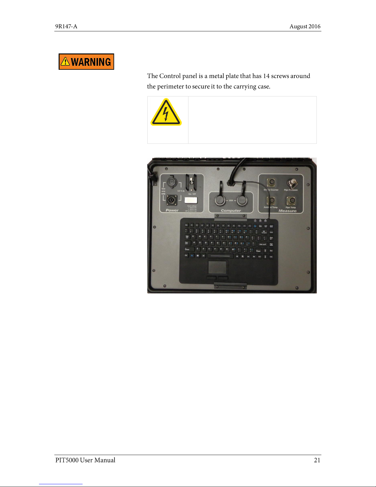
5. Control panel
Control panel plate
Hazardous voltage inside.
Risk of electric shock or burn.
The control panel should only be removed by
authorized electrical technicians.
Page 22

6. Industrial Keyboard
Keyboard
Note: No mouse is included.
Serial number label
7. Serial number label
Page 23

Software
Time impacts data logging and reports
Important: You cannot change the time zones,
only the time.
One easy step to check the time
Window
Window
Second—zero the pressure
First—check the computer’s time
Page 24

If the time is incorrect
Set the time in Windows 10
End Test Yes
Date and time settings
Time & Language
Page 25

Second—zero the pressure
Zero the pressure
Note: Since ambient air pressure depends on altitude
and weather, you should use the PIT5000 application to
zero for the current conditions.
Setup
PC Setup Zero Pressure
No required edit boxes to fill-in
Setup Report 1
Report 2
Note: Enter the data your testing requires and consider
entering N/A in edit boxes that you do not need. N/A
would quickly identify them as not required information
on reports.
Overview
Flexibility in the PIT5000 application
The main tabs in the application
Page 26

Setup tab
The Setup tab has five (5) sub-tabs
the Setup sub-tabs
Start Program
Setup tab locked
Setup
Start Program Begin Test
Note: The information remains viewable. A small button
appears to the right of the main tabs. It has a downarrow to view the various sub-tabs. See the section
called Locked data for more information.
Page 27

Test Info sub-tab—Report 1 (the original report)
Test Info sub-tab
Report 1
Active Report
Report 2.
Test Info figure for Report 1
Change engineering units in Test Info
Pressure Temp, Length
Start Program
Pressure
psi, kg/cm2, kPa, bar
Temperature
deg F, deg C
Length
feet, meters
Stroke Volume
gallons, liters
Page 28
Test Info sub-tab—Report 1 (continued)
T-Pipe Required button
T-Pipe Required
T-Pipe Not Required
Data Save Interval in minutes
Data Save
Interval in minutes
Data Save Interval in minutes
Examples:
Data
Reports 1 and 2
Page 29

Pump Info sub-tab
Enter pressure pump information
Stroke Count Required YES
Pump Model Number Pump Serial Number
If the stroke count function is required
Stroke Start Pressure
Note: This number appears in the Stroke Start view-only
box in the Test Limits sub-tab.
Stroke Rate Target.
Note: The Pump Contact Switch Closed indicator
provides visual verification that the contacts are opening
and closing before you start the data logging process.
Page 30

Pump Info sub-tab (continued)
If the stroke count function is not required
Stroke Count Required
NO
Report 1
Report 1 Test Info
Enter one pressure and several elevation points
Note: The application uses this information to calculate
the pressures at the other elevations.
Report 2
Report 2
Report 2—enhanced report
Site Info sub-tab—Report 1 (the original report)
Page 31

Test Limits sub-tab
The Test Limits
Enter the information for your Test Limits
Test Time:
Note: The Test Time appears as Elapsed Time in the
Data Panel after you click Start Program or Begin Test
buttons
PTest Instrument Pressure:
PIT5000 Pressure Site Info
Note: Once a test begins, the PTest edit box in the Data
Panel flashes red when the pressure goes above or
below the PTest Limits.
P Leak Pressure:
Note: Some customers perform a 15-minute, preliminary
leak test before going to higher pressures.
Stroke Start: Stroke Start
Pressure Pump Info
Pressure Rate Limits:
Pressure Rate
PTest High and Low Limits:
Page 32

PC Setup sub-tab
The Get Cal Data button
PC Setup
Note: Measurement device serial numbers are not
stored in the computer’s memory. They are retrieved
from the measurement device each time you click the
Get Cal Data button.
The Communication Port
Get Cal Data
COM3
Page 33

PC Setup sub-tab (continued)
Build Report button
Page 34

Locked data
View locked information
Setup
Start Program
Setup
Note: The button is located to the right of the Stroke
Count tab.
Example of a locked data sub-tab
Test Info
Data Panel
Note: the flashing red alarm in the Data Panel indicates
the range is above or below the range that you specified.
Page 2 of Site Info is not viewable
Note: This applies only to Report 2.
Page 35
Report 2—the enhanced report
The advantage of Report 2
Test Info tab for Report 2
Report 2
Site Info tab for Report 2
Site Info Report 1
Next
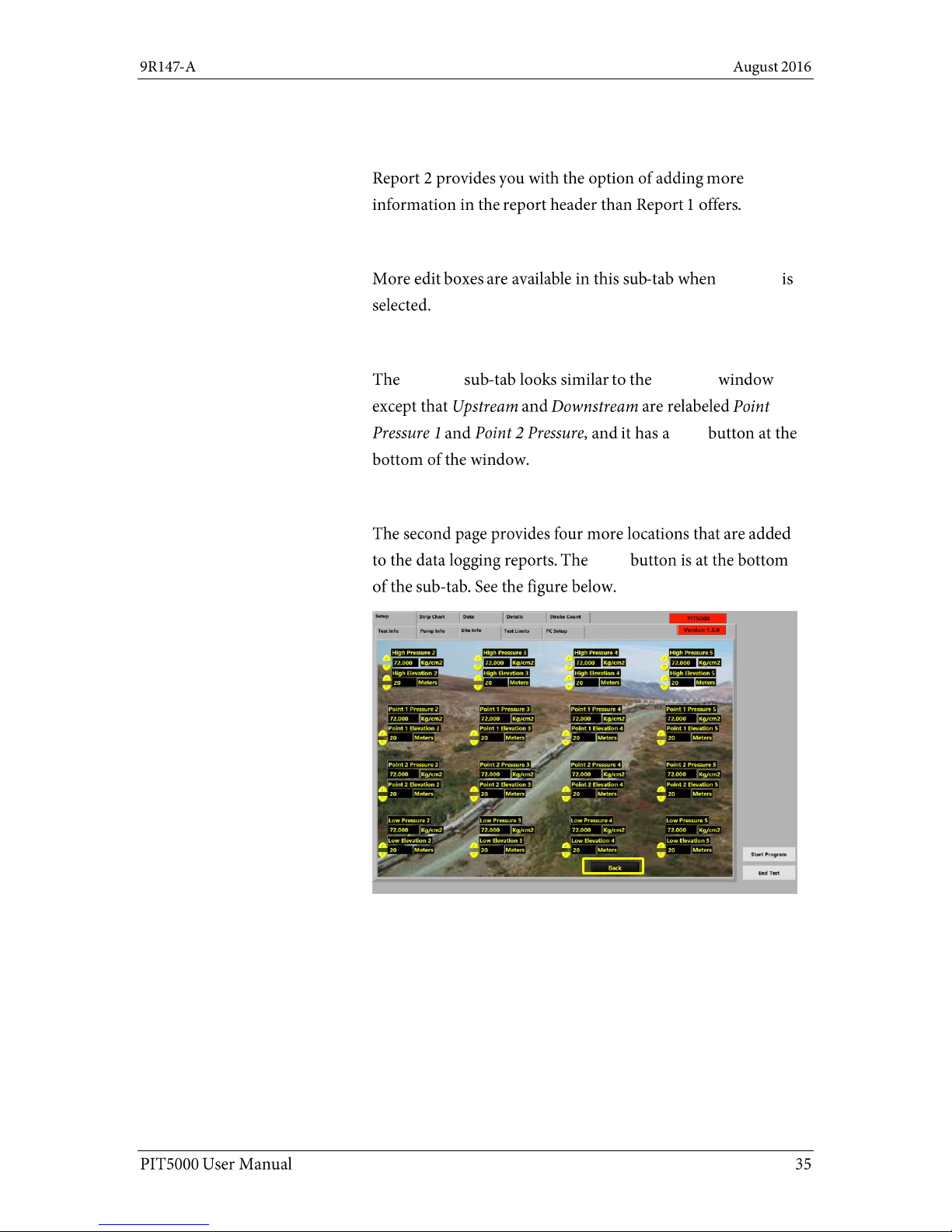
Site Info tab has a second page
Back
Page 36

Data Panel
Where is the Data Panel located?
What does the Data Panel display
before you click the Start Program
button?
Page 37

Data Panel (continued)
What does the Data Panel display
after you click the Start Program
button?
Note: This data is logged in a report.
The stroke count would be included
in the logged data at this time if you
had entered that information in the
Pump Info sub-tab.
Start Program
Begin Test
Note: You can monitor the pressure
and temperature readings before
beginning a timed test. After you are
satisfied that your initial test criteria
is met, you start the timed test by
clicking the Begin Test button.
What does the Data Panel display
after you click the Begin Test
button?
Note: this Elapsed Time is identical to
what you see displayed in the Details
tab.
Page 38

Data Panel (Continued)
What does the Data Panel display
when a timed-test is complete?
Time Complete
Note: Data logging continues until
you click the End Test button.
The Data Panel also displays
flashing red alarms
Setup
Page 39
Add Note button
What is the Add Note button?
Add Note
Start Program Begin Test
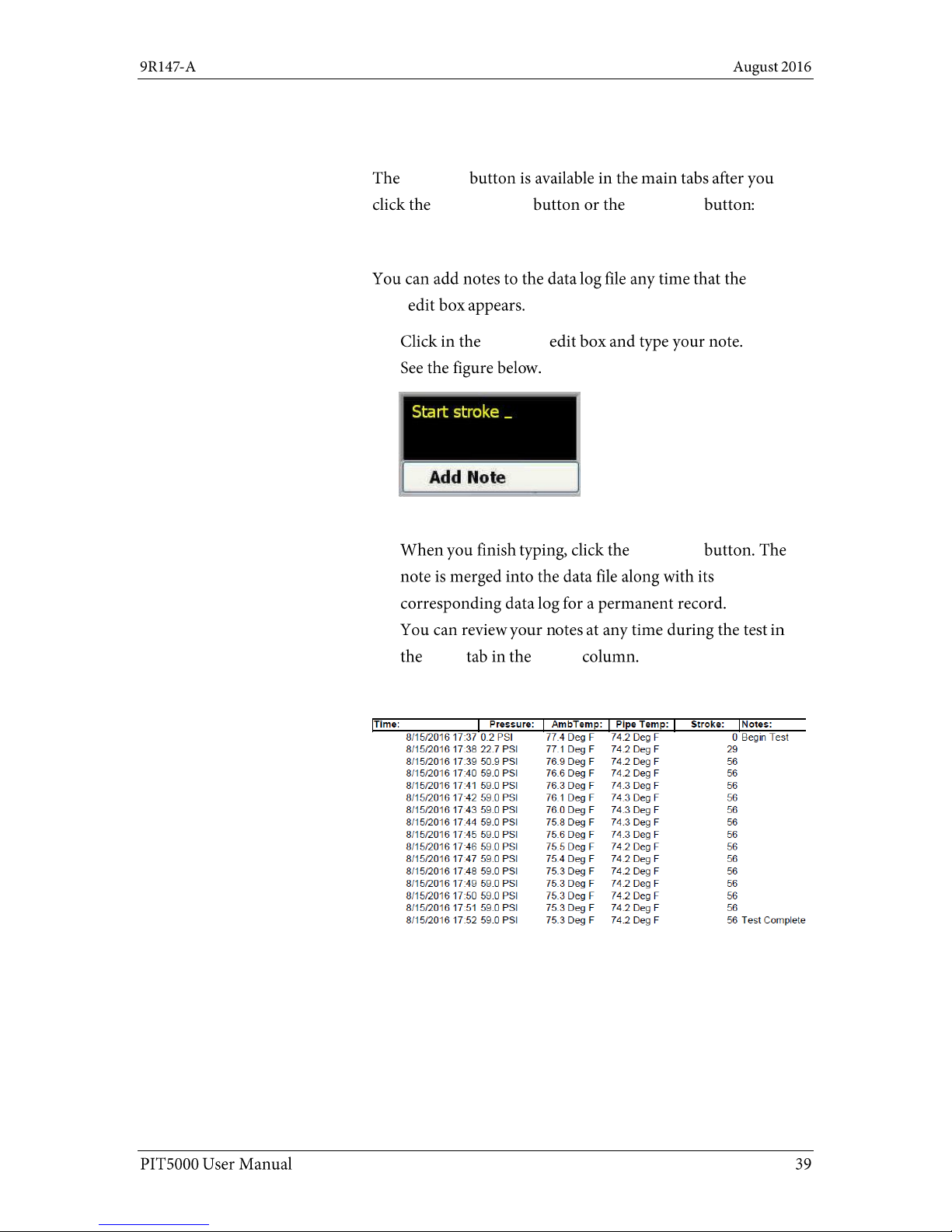
When can notes be added?
Add
Note
Add Note
Note: A note has a limit of 60 characters.
Add Note
Data Notes
Examples of notes added to the data log
Page 40
End Test button
What happens when the End Test button is
clicked?
Do you really want to stop the test?
1. Yes, I want to STOP the test.
Note: Clicking YES stops the test, saves the reports,
and closes the PIT5000 application. The application
will continue to display until the reports are saved.
The longer the data log, the longer you will have to
wait for the application to finish saving the files.
2. No, I want to continue.
Note: Clicking NO returns you to the ongoing test.
Clicking the Close button (the “X”) on the dialog box
is the same as clicking NO.
Ready to shut down and disconnect?
Shut down and disconnect
Transfer folders or files to a USB Flash Drive
End Test
File Explorer
D:\PIT5000\DATA
Important:
Page 41
Strip Chart tab
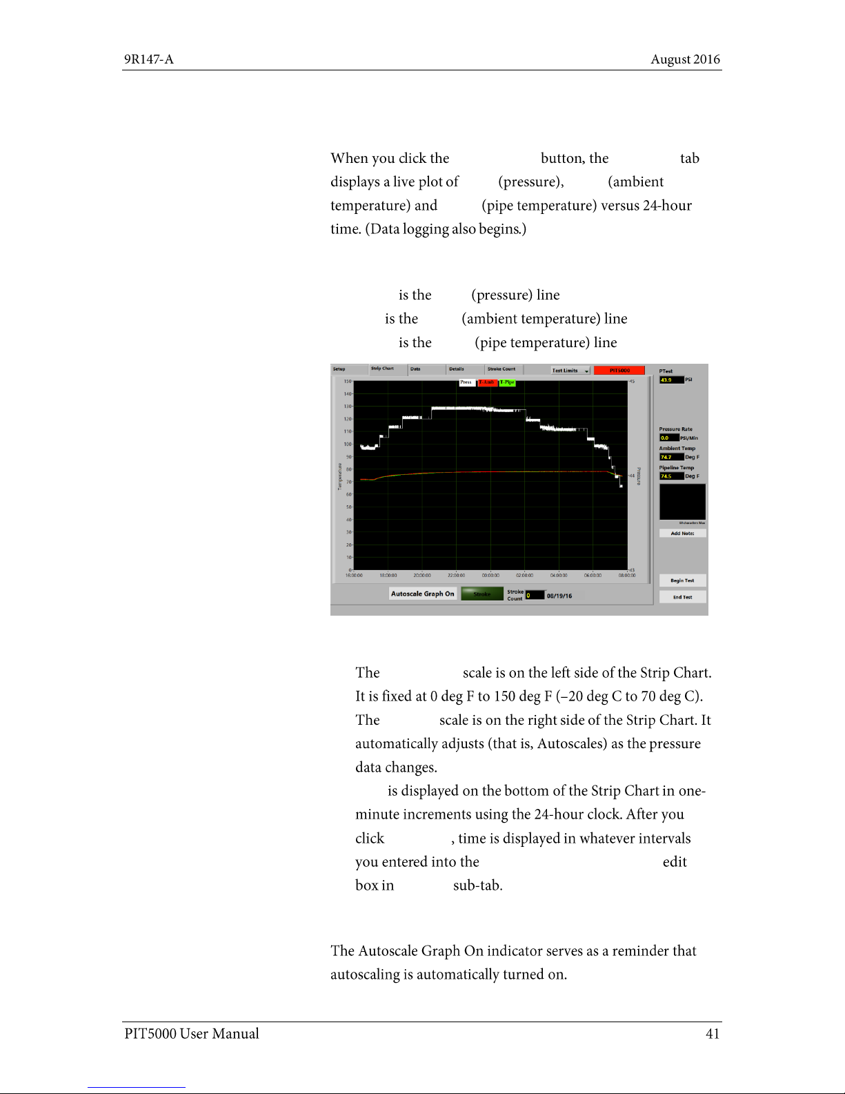
View a live plot of pressure and temperature
Start Program Strip Chart
Press T-Amb
T-Pipe
Strip Chart colors
White Press
Red T-Amb
Green T-Pipe
Strip Chart scales
Temperature
Pressure
Time
Begin Test
Data Save Interval in Minutes
Test Info
Autoscale Graph On
Page 42

Strip Chart tab (continued)
Stroke indicator
Stroke
Stroke indicator
Gray
Green
Double Stroke
Yellow
Double Stroke
Red
Double Stroke
The Stroke Count number box
Total
Count Stroke Count
Page 43
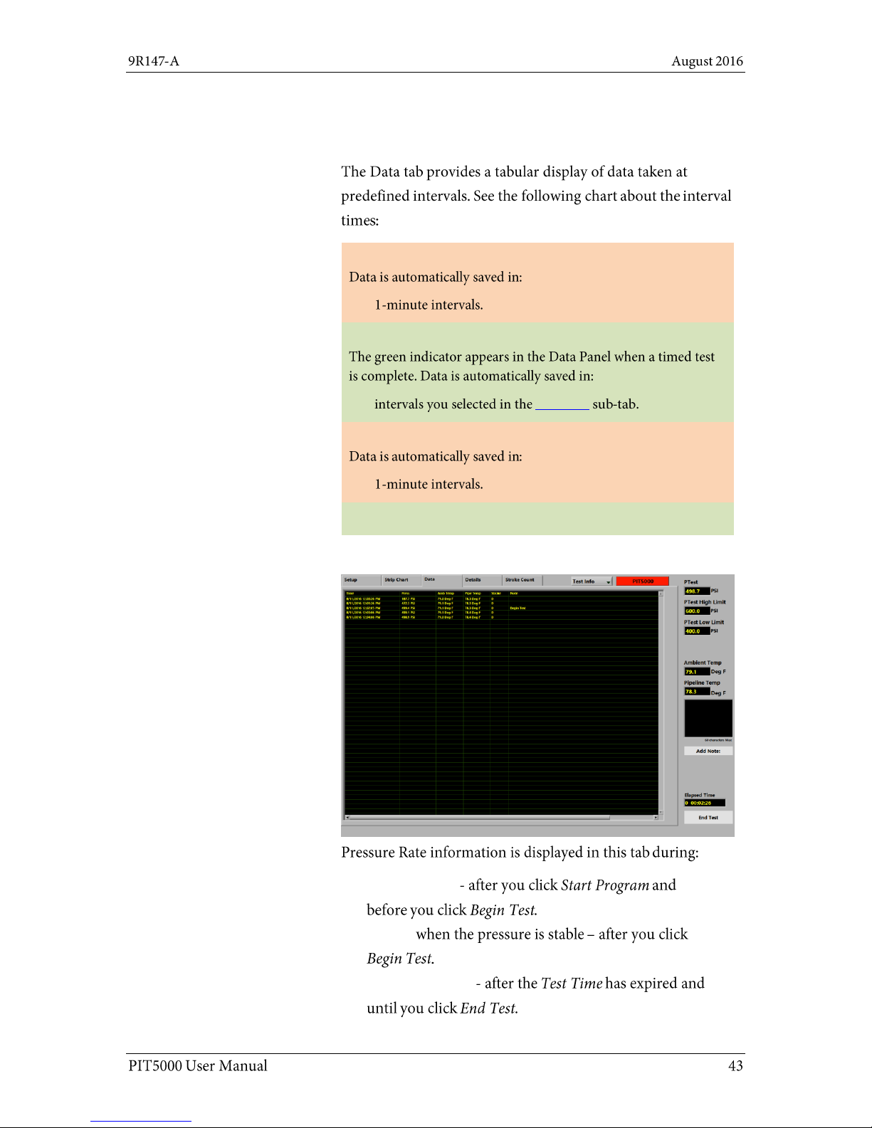
Data tab
Data tab overview
Between Start Program and Begin Test:
Between Begin Test to Time Complete:
Test Info
After Time Complete:
Data logging stops at End Test.
Pressure Rate information
Pressurization
Testing
Depressurization
Page 44
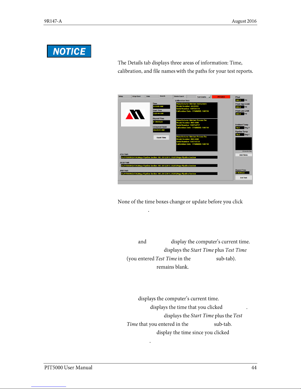
Details tab
The Details tab
Important: Live readings display in this tab only after
you click Start Program.
The Time boxes before “Start Program”
Start Program
The Time boxes between “Start Program” and
“Begin Test”
Time Start Time
Estimated Finish
Test Limits
Elapsed Time
The Time boxes between “Begin Test” and
“End Test”
Time
Start Time Begin Test
Estimated Finish
Test Limits
Elapsed Time
Begin Test
Page 45
Details tab (reset, calibration, paths)
The Reset Time button
Reset Begin Test
Start Time = the time when the Reset button was clicked.
Elapsed Time = 0.
Estimated Finish = Start Time + Test Time.
Note: The Timed Test resumes until you reach the new
Estimated Finish.
Calibration data
Start
Program
PC Setup sub-tab
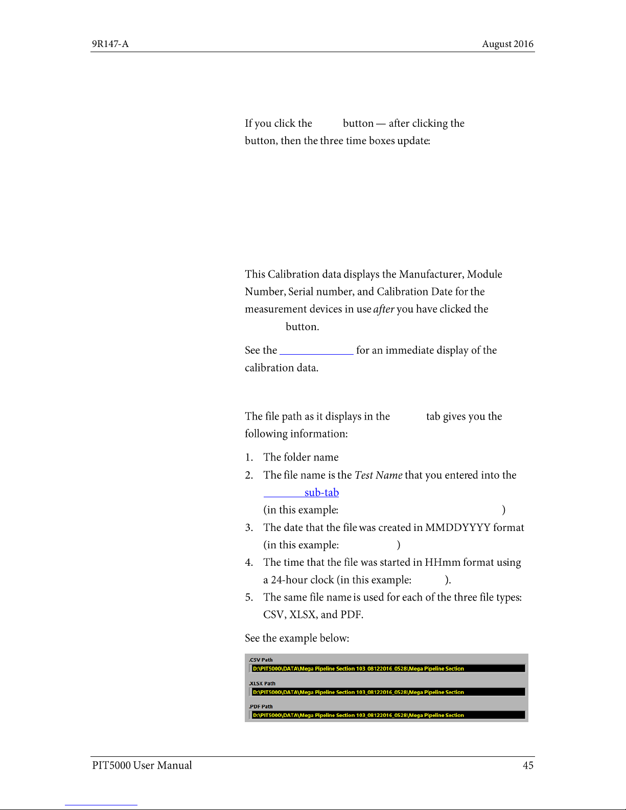
What does the path name mean?
Details
D:\PIT5000\Data.
Test Info
Mega Pipeline Section 103_
08122016_
0528_
Page 46
Details tab (do not delete these files)
Do not delete these files or folders
\DATA
PIT Report.xlsx
PIT Report Macro.xlsx.
\DATA
Page 47
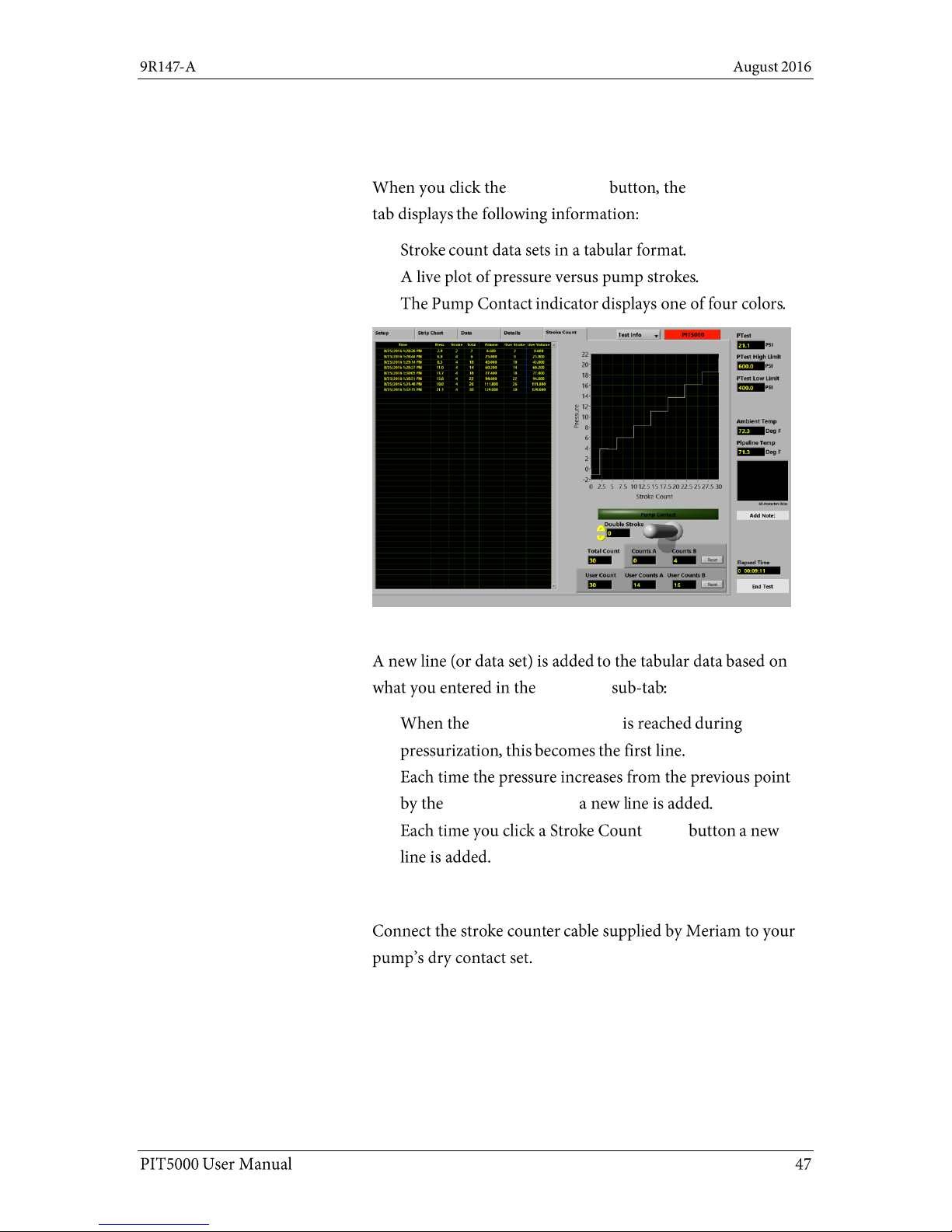
Stroke Count tab
Stroke Count description
Start Program Stroke Count
The tabular data
Pump Info
Stroke Start Pressure
Stroke Rate Target
Reset
Connect your set of dry contacts
Note: The PIT5000 supplies +5 V dc output to the dry
contact set and counts pump strokes based on contact
closures.
Page 48

Stroke Count tab (continued)
Pump Contact indicator
Gray
Green
Double Stroke
Yellow
Double Stroke
Red
Double Stroke
Proper interpretation of Stroke Counter data
Double Stroke Count box
Data Panel
Stroke Rate Target
Double Stroke
Page 49

Stroke Count tab (continued)
The function of the animated toggle switch
Describing the animated toggle switch figure
Counts A
Counts B
Note: When the toggle switch points right, then Counts A
represents the previous interval stroke count and
Counts B represents the current interval stroke count.
Total Count of strokes
Total Count
Stroke Start Pressure
PTest
Instrument Pressure
Page 50

Stroke Count tab (continued)
Counts A and Counts B Reset
Reset
Note: the Count Reset buttons do not affect the Total
Count edit box.
User Count
User Count
User Count User Volume
User Counts A
User Counts B
Reset
Reset
Page 51

Shut down and disconnect
Close the PIT5000 Application
End Test Data Panel
YES
Turn off the power
Off
Disconnect hose and cables
Page 52
Appendices
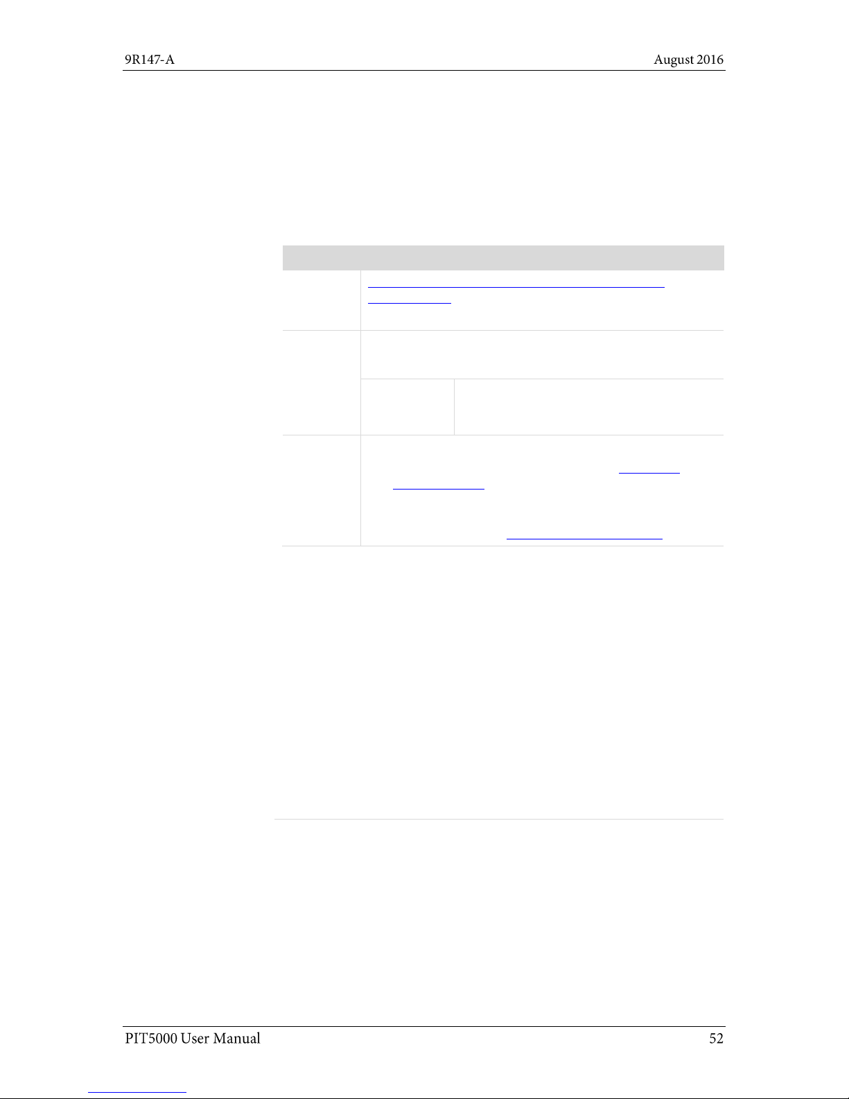
First — Request a Number
In the event that a PIT5000 requires service and must be returned,
please contact Meriam using one of the methods listed in the following
table to request a Return Material Authorization (RMA) number:
Method
Information
Website:
http://www.meriam.com/resources/service-repairauthorization/
Complete the information online and submit the form.
Fax:
If you printed and completed the Service & Repair
Authorization form, then fax it to:
US and
International
Customers
+ 1 216 281 0228
E-mail:
We need the following information in the email:
Look for the serial number label in the Computer
mounting panel to locate the model number & the
serial number.
Give a brief description of the problem.
Send the e-mail to: returnforms@meriam.com
Return Material Authorization
Do not send any unit for repair unless you contacted Meriam for a Return
Material Authorization (RMA) number.
Important: If you have not received this number and have not clearly
marked it on the package being shipped back, we will return the unit at
your expense.
The Meriam Service & Repair Department will provide you with this
number when you complete the website form, fax or e-mail your
information.
An RMA number must accompany all incoming packages to insure proper
tracking, processing, and repair work.
Questions? Call Meriam
US Customers
(800) 817-7849
International customers
+ 1 216 281 1100
Ship the box to
Meriam
10920 Madison Avenue
Cleveland, Ohio 44102
USA
Returning for repair or calibration
Page 53

Troubleshooting Guide
Symptom
Problem
Correction
An alarm sounds
inside the PIT5000
case
Low battery voltage (< 10.5 V)
has occurred and the internal
power inverter’s audible alarm
sounds.
Connect charger to the battery and
recharge it.
The voltmeter on
control panel reads
approximately 10.0 V
or less.
The computer does
not turn on or there
are no pressure or
temperature
measurements being
read.
Low battery voltage
(< 10.0 V) has resulted in a
shutdown of the internal
power inverter.
No power is going to the
measurement device or
computer power cord.
Turn the computer off if
necessary.
Move the power toggle switch to
Off.
Connect the charger to the
battery and recharge it.
The PIT5000 battery
does not charge.
Check for proper charger
operation (output should be
12 V dc).
Replace charger if needed.
The voltmeter on the
control panel
reads > 10.5 V and
the computer does not
turn on or there are no
pressure or
temperature
measurements being
read.
The PIT5000 power toggle switch
may be in the Off position.
Move the PIT5000 power toggle
switch to the On position. Turn the
computer on.
Internal power inverter locked up.
Turn computer off if necessary.
Move the power toggle switch to
Off and wait 1 minute.
Connect the charger to the
battery and recharge it.
Internal power inverter fuse may
have blown.
You will have to return the device for
repair to Meriam because it indicates
something is not working properly.
One or both
temperature
measurements fail to
plot.
RTDs not properly connected.
Check the connections of the
RTD cable on the Control Panel
and at the RTD.
There is a bad cable.
Swap RTD cables to see if the
problem follows the cable (one
measurement fails).
Replace the RTD cable as
needed.
Page 54

Symptom
Problem
Correction
Measurements (Press,
T-Amb & T-Pipe) are
not being plotted on
the Strip Chart in
PIT5000 application
This may be a USB
communication port issue.
Check the Communication Port
setting in the Setup tab > PC Setup
sub-tab. It should display COM3.
The output measurement may
have locked up.
Turn the computer off.
Move the toggle power switch to
Off and wait 1 minute.
Move the toggle power switch to
On.
Turn the computer on.
This may be a malfunction of the
Serial to USB converter.
Replace Serial to USB converter.
The Stroke counter
does not update in the
PIT5000 application
The counter signal is not being
received by the digital counter.
Check connection of counter
cable at the Control Panel and at
the dry contacts at the pressure
pump.
Confirm the counter cable is
delivering 5 V dc to dry contacts.
The stroke counter
cable does not deliver
5 V dc to the dry
contacts you
connected at the
pump.
The PIT5000’s digital counter has
an output failure.
Check wiring to the digital
counter.
Replace the faulty wire as
necessary.
The computer and
measurement device
do not turn on.
The power source is not
connected.
Connect the 12 V supply.
The power toggle switch is in the
Off position.
Move the PIT5000 power toggle
switch to the On position.
The time that is
displayed on the Strip
Chart’s x-axis is
incorrect.
The computer’s clock needs to be
set.
Time zones are not used. Only
Universal Coordinated Time (UTC)
is used.
Set the clock on the computer.
The PIT5000 application uses the
computer clock for displaying
time.
The PIT5000
application did not
automatically start.
Start the PIT5000 application
manually.
Double click the PIT5000 icon on
desktop.
Page 55

Specifications
Case
Description
Durable case, hinged lid, four press & pull latches, weather resistant
when closed.
Dimensions
External dimensions: Length × Width × Depth.
25 in × 20 in × 12 in (63.5 cm × 50.8 cm × 30.48 cm).
Weight
The case weight with the PIT5000 equipment is 42 lbs.
Mobility
In-line wheels.
An extendable handle.
Three additional handles around the perimeter.
External Power
115 V ac to 12 V dc power supply (charger assembly) has a cord that
is 9.5 feet.
12 V dc has a cord that is 25 feet (12 V locking, ring terminals).
Pressure limits
PIT5000 sensor: 0 psi to 3300 psi
Do not exceed the sensor limit.
Full Scale calibrated range = 100 % of range.
The PIT5000 application does not alert you to pressure limits.
Stroke Counter
PIT5000 supplies +5 V output to pump for Stroke Counter function.
M12 connection to PIT5000 through the Meriam cable with number 8
spade terminals for connection to dry contacts.
Maximum count rate: 300 strokes per minute.
Connections
Pressure
Quick-test fitting and hose.
Temperature
One M12 (female) for ambient temperature.
One M12 (female) for pipe temperature.
Stroke Counter
M12 (female).
Power
12 V car adapter.
12 V locking connector.
Operating temperature range
Computer working
temperature
5 ºC to 35 ºC (41 ºF to 95 ºF)
Storage temperature
–20 ºC to 60 ºC (–4 ºF to 140 ºF)
Page 56

Specifications (continued)
Application update rates
Strip Chart
The Strip Chart updates once every two (2) seconds.
Data Logging
Between Start Program and Begin Test: Data is automatically
saved in one-minute intervals.
Between Begin Test to Time Complete:
The green indicator appears in the Data Panel when a timed
test is complete. Data is automatically saved in intervals you
selected in the Test Info sub-tab.
After Time Complete: Data is automatically saved in oneminute intervals.
Data logging stops at End Test.
Certifications
NIST traceable certificates for pressure and temperature modules.
CE mark for the measurement device.
CE mark for computer.
Page 57

Part numbers
Contact Meriam about these part numbers
sales@meriam.com
+ 1 216 281 1100 (800) 817-7849
Part
Numbers
Descriptions
Replacement parts
Z9A686
Battery Charger Assembly.
Z9A821
RTD Probe Assembly. Pt100, 4-wire, class A,
Alpha Coefficent 0.003 85
Z9A1383
RTD Cable Assembly, 150 Ft.
Z9A1385
High Pressure Hose Assembly, 150 Ft.
(rated for 5000 psi)
Z9A1386
Stroke Counter Cable Assembly, 150 Ft.
Z9A1395
Power cable 12 V Locking.
Z9P495
Quick-test Adapter.
Z9P555
Nylon Gear Bag.
Z9P562
Hose Reel.
Z9P1455
Fuse – 20 A 32 V ac / V dc for the 12 V locking
cable assembly.
Optional parts
Z9A685
12 V car adapter DC-to-DC cable.
Z9A805
Air Purge Kit.
Z9P511
Battery.
Z9P688
Battery Box.
 Loading...