

Meriam M400-CI0300-02, M400-CI1000-02, M400-CI3000-02, M400-AI1000-02, M400-GI3000-02 User manual
...Page 1

ZM4 Instruction Manual 9R87-B June 2012
MM44 SSeerriieess HHaannddhheelldd PPrreessssuurree
aanndd LLoooopp CCaalliibbrraattoorr
Find Quality Products Online at: sales@GlobalTestSupply.com
www.GlobalTestSupply.com
Page 2

ZM4 Instruction Manual 9R87-B June 2012
Table of Contents
Certification and Safety .............................................................. 4
Product Overview ........................................................................ 6
Keys and Functions .................................................................... 7
Measure Mode ............................................................................. 9
Main Unit Setup ......................................................................... 10
Power Management Setup........................................................ 11
Data Logging Setup .................................................................. 12
Date & Time Setup..................................................................... 14
Security Setup ........................................................................... 15
Pressure Sensor Setup ............................................................. 17
Damping Setup .......................................................................... 18
Calibration Setup....................................................................... 19
Field Recalibration .................................................................... 20
Units Selection Setup ............................................................... 21
Volts/mA Sensor Setup............................................................. 22
Volts/mA Mode Setup ............................................................... 23
Volts/mA Source and Sink Setup ............................................ 24
Volts/mA Auto Step Setup........................................................ 25
Volts/mA Auto Ramp Setup ..................................................... 26
Changing Batteries .................................................................. 27
Accessing SD Card ................................................................... 28
Downloading Data Using USB Interface ................................. 29
Installing Wire Stand ................................................................. 30
Range Specifications ................................................................ 31
Specifications ............................................................................ 33
Zeroing and Field Recalibration .............................................. 36
Applications ............................................................................... 37
Contact Meriam ......................................................................... 40
Find Quality Products Online at: sales@GlobalTestSupply.com
www.GlobalTestSupply.com
Page 3

ZM4 Instruction Manual 9R87-B June 2012
Figures
Figure 1: Inputs and Outputs 6
Figure 2: Keypad Functions 7
Figure 3: Keypad Functions 8
Figure 4: Measure Mode Display 9
Figure 5: Main Unit Setup Display 10
Figure 6: Power Management Setup Display 11
Figure 7: Data Logging Setup Display 12
Figure 8: Data Logging Status Display 13
Figure 9: Date & Time Setup Display 14
Figure 10: Security Setup Display 15
Figure 11: Password Change Display 16
Figure 12: Pressure Sensor Setup Display 17
Figure 13: Damping Setup Display 18
Figure 14: Pressure Sensor Calibration Setup Display 19
Figure 15: Field Recalibration Display 20
Figure 16: Pressure Units Selection Display 21
Figure 17: Volts/mA Sensor Setup Display 22
Figure 18: Volts/mA Mode Select Display 23
Figure 19: Volts/mA Source and Sink Setup Display 24
Figure 20: Volts/mA Auto Step Setup Display 25
Figure 21: Volts/mA Auto Ramp Setup Display 26
Figure 22: Changing Batteries 27
Figure 23: Accessing SD Card 28
Figure 24: Installing Wire Stand 30
Thank you for purchasing this product. Meriam has been providing
innovative, reliable, cost effective measurement and calibration solutions for
100 years. The M400 Single Sensor or M402 Dual Sensor Handheld
Pressure Transmitter Calibrator continues this legacy and is the first of its
kind for the process measurement industry.
3
Find Quality Products Online at: sales@GlobalTestSupply.com
www.GlobalTestSupply.com
Page 4
ZM4 Instruction Manual 9R87-B June 2012
Certification/Safety/Warnings
Fire/Explosion Hazard. This instrument is not intrinsically
safe. DO NOT use in areas that may contain flammable
gas or vapors, combustible dusts or ignitable fibers where an unintended
spark can cause a fire/explosion.
Do not exceed the Pressure Limits listed in the
Specifications section of this manual. Failure to operate
within the specified pressure limit could result in minor or moderate injury
Substitution of components may impair operation and safety.
Disconnect power before servicing.
The product should not be powered with a combination of new and old
batteries.
The product should not be powered with a combination of batteries from
different manufacturers.
User must use a wrench on the pressure manifold
when installing user’s 1/8” NPT fitting. Do not tighten
the fitting without using a wrench on the pressure manifold. Failure to use a
wrench on the manifold will damage the plastic enclosure and void warranty
No torque should be applied to the manifold with respect to plastic enclosure.
Safety Information
Failure to follow all instructions could result in injury. Read,
understand and follow all safety warnings and instructions provided
with this product. Also, meet or exceed your employer’s safety
practices.
In no event shall Meriam be liable for any indirect, special, incidental,
consequential or punitive damages or for any lost profits arising out of or
relating to any services provided by Meriam or its affiliates. It is not possible
for Meriam to identify all foreseeable uses/misuses, therefore all persons
involved in commissioning, using or maintaining this product must satisfy
themselves that each intended application is acceptable.
4
Find Quality Products Online at: sales@GlobalTestSupply.com
www.GlobalTestSupply.com
Page 5
ZM4 Instruction Manual 9R87-B June 2012
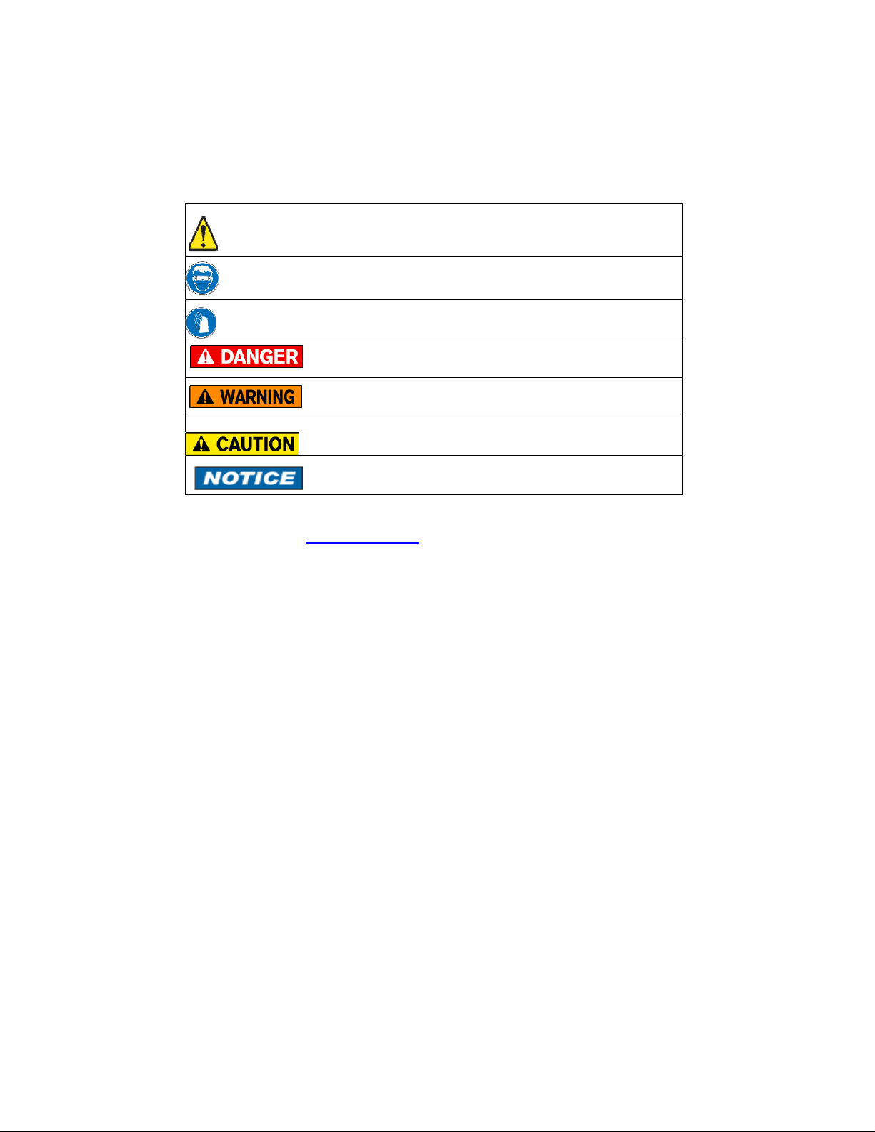
Safety Warnings
The table below defines the safety symbols, signal words and corresponding
safety messages used in the manual to identify potential hazards and are
intended to warn persons about hazards that could result in personal injury or
equipment damage.
This is the Safety Alert symbol. This symbol indicates a WARNING. Warnings
alert you to actions that can cause personal injury or pose a physical threat.
Please read these carefully.
This is the Safety Glasses symbol. This symbol indicates that you must wear
approved safety glasses during the task.
This is the Safety Gloves symbol. This symbol indicates that you must wear
approved safety gloves during the task.
Indicates a potentially hazardous situation which, if not
avoided, will result in death or serious injury.
Indicates a potentially hazardous situation which, if not
avoided, could result in death or serious injury.
Indicates a potentially hazardous situation which, if not avoided,
could result in minor or moderate injury.
Indicates information essential for proper product installation,
operation or maintenance.
Information in this document is subject to change without notice. Check the
Meriam web site (www.meriam.com) for the latest manual revision.
5
Find Quality Products Online at: sales@GlobalTestSupply.com
www.GlobalTestSupply.com
Page 6

ZM4 Instruction Manual 9R87-B June 2012
1
3
4
1
Product Overview
2
Figure 1: M4 Inputs and Outputs
Number Name Description
Pressure Manifold
Connection
Connects the calibrator to a pressure
source via 1/8” NPT Female.
M400 = One Pressure Sensor
M402 = Two Pressure Sensors
USB Connection Connects the calibrator to a computer
2
using a USB Mini Type B to USB
Standard Type A cable.
Measure Volts/mA
3
Source Volts/mA
Terminals
4
Battery/SD Card
Access
Terminals for measuring or sourcing
both Volts and mA DC.
50VDC and 100mA max.
4x1.5V AA batteries and SD card for
data logging
NOTES:
Batteries must be installed for Volts/mA measurement and simulation
operation.
When the unit is attached to a high power USB port, everything except for
the Volts/mA sensor runs from USB power.
Volts/mA measurement or simulation should not be used with USB attached
unless the USB power source is isolated.
6
Find Quality Products Online at: sales@GlobalTestSupply.com
www.GlobalTestSupply.com
Page 7

ZM4 Instruction Manual 9R87-B June 2012
2
1
3
4
1
Keys and Functions
Figure 2: Keypad Functions
Number Key Description
Turns the power On and
Off.
2
3
Turns green backlight
On and Off.
Function Keys F1 – F4
Change depending on
Operation Mode
4
Adaptive interface wheel
scrolls up and down
through menu options or
increments or
decrements a value.
7
Find Quality Products Online at: sales@GlobalTestSupply.com
www.GlobalTestSupply.com
Page 8

ZM4 Instruction Manual 9R87-B June 2012
6
5
7
8
9
6
Keys and Functions
Figure 3: Keypad Functions
Number Key Description
5
7
8
9
Left Arrow – Navigates back out of
menu or moves cursor
Right Arrow – Navigates further
into menu structure, moves cursor,
or selects value
Sensor – Highlights sensor of
interest for configuring or viewing
settings
Units – Changes engineering units
of a pressure sensor that is
highlighted. Units for the Volts/mA
module are set automatically
according to the measure/simulate
mode.
Setup – Enters the setup menu for
the unit or individual sensor that is
selected or highlighted
8
Find Quality Products Online at: sales@GlobalTestSupply.com
www.GlobalTestSupply.com
Page 9

ZM4 Instruction Manual 9R87-B June 2012
Measure Mode
Figure 4: Measure Mode Display with All Indicators Shown
Icon or Reference Function
HOLD Values are held on display for reference.
REC Data logging function is ON and calibrator is
recording information.
USB USB cable is connected to the calibrator.
100% Battery life as a percentage value.
10:35 AM Current time display.
P1: Type XXX Pressure Sensor #1, Type, and Full Scale
Range in units selected. See specifications
for further details.
P2: Type XXX Pressure Sensor #2, Type, and Full Scale
Range in units selected. See specifications
for further details. M400 units will have N/A
displayed on the screen.
VI: Mode Voltage/mA Sensor and current operation
mode selected.
▲▼ Indicators for Maximum and Minimum
measured or limit values.
T Tare indicator.
50.0% Simulation value as a percent of full scale
/ Indicator for auto simulation mode:
ramp(shown), step or paused.
RANGE Unit is operating with a soft or hard over
range limit. See over and under range table.
Hold Function Key to toggle the hold function of
the displayed values.
Mn/Mx Function Key to reset the displayed
maximum and minimum values.
9
Find Quality Products Online at: sales@GlobalTestSupply.com
www.GlobalTestSupply.com
Page 10

ZM4 Instruction Manual 9R87-B June 2012
Main Unit Setup
Figure 5: Main Unit Setup Display
Reference Function
Contrast Adjust Adjust contrast of display. Active setting
shown on right.
Power Mgmt Adjust Auto Off Timer, Backlight Timer, or
Backlight Intensity to improve battery life.
Data Logging Start, Stop, and setup parameters for a data
log session.
Date & Time Adjust date and time.
Security Adjust security settings such as password,
feature lockouts, etc
Information Displays Product ID, Serial Number and
Firmware Version.
10
Find Quality Products Online at: sales@GlobalTestSupply.com
www.GlobalTestSupply.com
Page 11

ZM4 Instruction Manual 9R87-B June 2012
Power Management Setup
Figure 6: Power Management Setup Display
Reference Function
Auto Off Timer Automatic power off timer selection. Active
setting shown on right.
Backlight Timer Automatic backlight shut off timer selection.
Active setting shown on right.
Backlight Level Backlight brightness control. Active setting
shown on right.
NOTE:
To maximize battery life, if the backlight is frequently used, reduce the
backlight level. Also consider using the backlight timer to avoid the backlight
being left on for long periods of time.
11
Find Quality Products Online at: sales@GlobalTestSupply.com
www.GlobalTestSupply.com
Page 12

ZM4 Instruction Manual 9R87-B June 2012
Data Logging Setup
Figure 7: Data Logging Setup Display
Reference Function
Start Start the data log using the current settings.
Stop Stop or cancel the running data log.
Interval Adjust the data log interval time between 1
and 60 seconds. Active setting shown on
right.
Duration Adjust the data log duration time between 1
minute and 24 hours. Active setting shown
on right.
Log Name Adjust the name of the data log. Press right
arrow to bring up menu to enter name for
data log session.
Status Status of the data log session. Active status
displayed on right. Press right arrow to bring
up detailed information (shown in Fig. 8).
12
Find Quality Products Online at: sales@GlobalTestSupply.com
www.GlobalTestSupply.com
Page 13

ZM4 Instruction Manual 9R87-B June 2012
Figure 8: Data Logging Status Display
The data log status display shows the configured Log Name, Interval and
Duration at the top.
At the bottom of the display, real-time data including Status, completion
percentage and remaining time are shown.
13
Find Quality Products Online at: sales@GlobalTestSupply.com
www.GlobalTestSupply.com
Page 14

ZM4 Instruction Manual 9R87-B June 2012
Date & Time Setup
Figure 9: Date & Time Setup Display
Use the arrow keys to highlight the appropriate field. Set the correct value
using the Adaptive Interface Wheel.
To save the new date & time press the Save key. All the fields will
temporarily display dashes while the new values are stored. To cancel
without saving, press the Exit key.
NOTE: The seconds field (ss) is not adjustable. The time can only be
adjusted to the nearest minute. When the Save key is pressed the seconds
are set to zero.
14
Find Quality Products Online at: sales@GlobalTestSupply.com
www.GlobalTestSupply.com
Page 15

ZM4 Instruction Manual 9R87-B June 2012
Security Setup
The Security feature allows you to protect sensitive functions of the device.
At this time only the Field Recalibration functions can be protected. The lock
indicator shown in Fig 10 above indicates whether Field Recalibration is
locked or unlocked (as shown).
To change the security on Field Recalibration press the right arrow key when
“Field Recalibration” highlighted. The lock indicator to the right will toggle
between lock and unlock. If you have not entered the security password
since the current power cycle you will first be prompted to enter it. Use the
Adaptive Interface Wheel and arrow keys to enter the characters in the
password prompt screen. Once you have entered the correct password you
can modify the security function until the next time the unit is powered up.
NOTE:
The default password for factory new units is “PASSWORD”. It is strongly
suggested that the password be changed when the unit is first received.
Figure 10: Security Setup Display
Reference Function
Field recalibration Set the lockout of the Field Recalibration
function. Current lock setting shown on right.
Change Password Modify the existing password. Press right
arrow to bring up password change screen
(shown in Fig. 11).
15
Find Quality Products Online at: sales@GlobalTestSupply.com
www.GlobalTestSupply.com
Page 16

ZM4 Instruction Manual 9R87-B June 2012
The Change Password function allows you to set a new password. The
screen shown in Fig. 11 shown below displays this function. Enter the current
password on the first line. Use the Adaptive Interface Wheel and arrow keys
to enter the characters. Using the Next key tab down to the New Password
line to redefine the password and then down to the Confirm Password line to
reenter the new setting. Press Enter to confirm the new password.
The password is 10 characters in length and is made up of any combination
of upper case alpha and numeric characters.
Figure 11: Password Change Display
16
Find Quality Products Online at: sales@GlobalTestSupply.com
www.GlobalTestSupply.com
Page 17

ZM4 Instruction Manual 9R87-B June 2012
Pressure Sensor Setup
Figure 12: Pressure Sensor Setup Display
Reference Function
Damping Enable or disable damping and adjust value.
Active setting shown to the right.
Calibration Zero, Field Calibrate, or Restore Factory
Defaults
Reset Min/Max Resets Min/Max values
Resolution Choose Accuracy or Precision resolution on
display for selected sensor. Active setting
shown to the right.
Units Selection Engineering units selection list. Used to
select which units are available when the
Units key is pressed
Information Displays Sensor Type, Accuracy, Calibration
Date, Serial #, and Range
NOTE: Pressure Sensor Setup applies to both P1 and P2 sensors.
17
Find Quality Products Online at: sales@GlobalTestSupply.com
www.GlobalTestSupply.com
Page 18

ZM4 Instruction Manual 9R87-B June 2012
Damping Setup
Figure 13: Damping Setup Display
Use the Type key to change the Damping Type. The options are a follows:
1) None. The measured value is not filtered or damped.
2) Exp(exponential), which uses a traditional damping algorithm with
response delays associated with the Damping Rate.
3) Smart, which employs a smart damping algorithm to produce and
instant response to a step change. After the step change it uses the
Damping Rate to damp the measurement exactly as in exponential
damping.
Use the arrow keys and the Adaptive Interface Wheel to set the Damping
Rate in seconds. The value can be adjusted between 0 and 32 seconds.
Press the Exit key to return to the main Pressure Sensor Setup menu.
18
Find Quality Products Online at: sales@GlobalTestSupply.com
www.GlobalTestSupply.com
Page 19

ZM4 Instruction Manual 9R87-B June 2012
Calibration Setup
Figure 14: Pressure Sensor Calibration Setup Display
Reference Function
Zero Perform a zero adjustment of the pressure
sensor at the applied input.
Field recalibration Enter field recalibration procedure.
Functionality is described on the following
page. Lock setting for operation displayed on
right. See NOTE below.
Restore Defaults Perform a restore defaults function. Lock
setting for operation displayed on right. See
NOTE below.
NOTE:
If the Field Recalibration or Restore Defaults functions are locked you must
first unlock them to enter the function. See the Security section for more
details.
19
Find Quality Products Online at: sales@GlobalTestSupply.com
www.GlobalTestSupply.com
Page 20

ZM4 Instruction Manual 9R87-B June 2012
Field Recalibration
Figure 15: Field Recalibration Display
The Field Recalibration Display contains the following:
1. The current calibration point and number of points displayed at the
top.
2. Under “Apply:” in the black highlighted area, the nominal calibration
point in the current pressure units for the sensor is displayed.
3. Under “Range:” the tolerance band around the nominal value.
4. The live pressure measurement in the current pressure units is
displayed at the bottom.
To run the field recalibration procedure:
1. Apply the pressure indicated in the “Apply:” field. The value must lie
within the tolerance band indicated by “Range:”
2. Press the Save key when you are at the correct input to calibrate.
The live display value will show dashes when the calibration point is
being saved.
3. Press the Next key to advance to the next calibration point. Repeat
steps 1&2 above.
4. Repeat steps 1-3 until you reach the last point.
5. At the last point the Next key is replaced with a Done key. When you
have finished calibrating the last point press the Done key.
6. A Calibration complete screen appears with Exit and Save keys.
Press Exit to discard the field recalibration. Press Save to store the
field recalibration results.
20
Find Quality Products Online at: sales@GlobalTestSupply.com
www.GlobalTestSupply.com
Page 21

ZM4 Instruction Manual 9R87-B June 2012
Units Selection Setup
Figure 16: Pressure Units Selection Display
This selection list shows which pressure units are displayed when the
Units key on the M4 is pressed. The units with the check mark to the
right will be displayed. Those without the check mark will be skipped.
To enable or disable a pressure unit, use the Adaptive Interface Wheel to
scroll to the desired unit. Press either arrow key to check or uncheck the
unit. The arrow keys will toggle the unit between checked and
unchecked.
To enable all 32 units press the All function key. To uncheck all the units
press the Clear key.
Press Exit to return to the main Pressure Sensor Setup menu.
NOTE: At least one pressure unit must be selected before exiting.
21
Find Quality Products Online at: sales@GlobalTestSupply.com
www.GlobalTestSupply.com
Page 22

ZM4 Instruction Manual 9R87-B June 2012
Volts/mA Sensor Setup
Figure 17: Volts/mA Sensor Setup Display
Reference Function
Mode Choose Volts Measure, mA Measure, 24V
Source, Volts Source, mA Source, or mA
Sink
Damping Enable or disable damping and adjust value.
Active setting shown to the right.
Calibration Perform a Zero, Field Calibration, or Restore
Factory Defaults
Reset Min/Max Resets Min/Max value
Resolution Choose Accuracy or Precision resolution on
display for selected sensor. Active setting
shown to the right.
Information Displays Sensor Type, Accuracy, Calibration
Date, Serial # and Range
NOTE:
Description of Mode setup is described in the following pages. Damping and
Calibration are described in the preceding pages covering Pressure Sensor
setup.
22
Find Quality Products Online at: sales@GlobalTestSupply.com
www.GlobalTestSupply.com
Page 23

ZM4 Instruction Manual 9R87-B June 2012
Volts/mA Mode Setup
Figure 18: Volts/mA Mode Select Display
Reference Function
V Measure Selects the voltage measure mode.
I Measure Selects the current measure mode.
24V Source Selects the 24V loop source mode.
V Source Selects the voltage source mode. Brings up
menu (described on following page) to select
manual or automatic voltage simulation.
I Source Selects the current source mode. Brings up
menu (described on following page) to select
manual or automatic current simulation.
I Sink Selects the current sink mode. Brings up
menu (described on following page) to select
manual or automatic current sink. This is
also known as transmitter simulation mode.
23
Find Quality Products Online at: sales@GlobalTestSupply.com
www.GlobalTestSupply.com
Page 24

ZM4 Instruction Manual 9R87-B June 2012
Volts/mA Source and Sink Setup
Figure 19: Volts/mA Source and Sink Setup Display
Reference Function
Manual Selects manual simulation. Brings up a
menu to set the initial simulation value and
start simulating.
Auto Step Selects auto step simulation. Brings up a
menu to configure the auto step procedure.
Auto Ramp Selects auto ramp simulation. Brings up a
menu to configure the auto ramp procedure.
Start Quick Ramp Starts a quick ramp simulation. The module
will continuously ramp between zero and full
scale in 15 seconds.
24
Find Quality Products Online at: sales@GlobalTestSupply.com
www.GlobalTestSupply.com
Page 25

ZM4 Instruction Manual 9R87-B June 2012
Volts/mA Auto Step Setup
Figure 20: Volts/mA Auto Step Setup Display
Reference Function
Start Select to start the Auto Step simulation.
Mode: Volts/mA mode for the simulation. For
reference only, cannot be modified here.
Begin Value: Starting simulation value. Brings up edit
display to change the value.
End Value: Ending simulation value. Brings up edit
display to change the value.
Num Steps: Number of steps in the procedure. Brings up
edit display to adjust the value between 1
and 10.
Dwell Time: Time to pause at each step before
advancing to the next step. Brings up edit
menu to select the value between Manual, 5
or 10 seconds.
Startup Delay:
(not shown in Fig 20)
Delay after pressing Start key before
simulation begins. Brings up edit menu to
select the value between None, 30 or 60
seconds.
25
Find Quality Products Online at: sales@GlobalTestSupply.com
www.GlobalTestSupply.com
Page 26

ZM4 Instruction Manual 9R87-B June 2012
Volts/mA Auto Ramp Setup
Figure 21: Volts/mA Auto Ramp Setup Display
Reference Function
Start Select to start the Auto Ramp simulation.
Mode: Volts/mA mode for the simulation. For
reference only, cannot be modified here.
Begin Value: Starting simulation value. Brings up edit
display to change the value.
End Value: Ending simulation value. Brings up edit
display to change the value.
Ramp Time: Time to ramp between the Begin and End
values. Brings up edit display to adjust the
value between 1 and 300 seconds.
Startup Delay:
Delay after pressing Start key before
simulation begins. Brings up edit menu to
select the value between None, 30 or 60
seconds.
26
Find Quality Products Online at: sales@GlobalTestSupply.com
www.GlobalTestSupply.com
Page 27

ZM4 Instruction Manual 9R87-B June 2012
Changing Batteries
Loosen the two screws in the battery cover and lift off cover. Remove the
batteries by gently applying pressure to the positive side and pull upward. To
install batteries (Four (4) AA 1.5 volt alkaline batteries) insert the negative
side against the spring and gently apply pressure to lock in the positive side.
The positive (+) and negative (-) battery polarity markings are located in the
bottom of the case for the lower batteries and on the top of case for the
upper batteries, as shown in the illustration. Once the batteries are secured
in the battery compartment, replace battery cover and tighten the two flat
head screws. The battery door is universal and can be installed in either
direction.
Figure 22: Changing Batteries
Warning – To avoid erratic readings replace batteries when
warning message appears.
27
Find Quality Products Online at: sales@GlobalTestSupply.com
www.GlobalTestSupply.com
Page 28

ZM4 Instruction Manual 9R87-B June 2012
Accessing SD Card
To install the SD™ card simply insert the card in the slot and press down
until you hear a click. The card has only one orientation for correct alignment.
Please make sure you are inserting a SANDISK P/N SDSDB-2048-A11 or
equivalent. Further details on the card are provided under the specification
section.
NOTE:
There is a Lock located on the side of the SD™ card. When the Lock is
pressed down information can only be read from the card. To write or save
information to the card make sure it is Unlocked before installing.
Figure 23: Accessing SD Card
28
Find Quality Products Online at: sales@GlobalTestSupply.com
www.GlobalTestSupply.com
Page 29

ZM4 Instruction Manual 9R87-B June 2012
Downloading Data Using USB Interface
The M4 has the capability to download the information stored on the SD card
to a computer via the USB cable provided with the unit or via an SD card
reader. The Meriam Setup Utility which allows you to download the data is
provided on the CD or available at www.meriam.com. Please install the USB
drivers before installing the program. The USB Interface is for the exchange
of data only. See precaution in Product Overview section regarding
measurements taken with USB connected.
The data file is downloaded as a .bin file and converted over to a .csv file for
direct use in Microsoft Excel™. Select Device Native
Output (USB) and press the Find Device button to find the M4.
Once the device is found press the Data Log Utility button and follow screen
instructions.
29
Find Quality Products Online at: sales@GlobalTestSupply.com
www.GlobalTestSupply.com
Page 30

ZM4 Instruction Manual 9R87-B June 2012
Installing Wire Stand
All M4 units come standard with an installed rear hand strap and a separate
wire stand. To install the wire stand first pull down on the loose end of the
Velcro strap to separate it, then carefully pull the strap through the lower
bracket. Next remove the two Phillips screws that secure the top metal
bracket.
Locate the plastic bag that contains the wire stand, rubber mounting bracket,
and two Phillips screws. Align the plastic mounting holes with the two brass
inserts. Please make sure the straight edge is facing upward toward the
pressure manifold as shown in the illustration. Secure the plastic mounting
block to the enclosure by tightening the screws.
Figure 24: Installing Wire Stand
30
Find Quality Products Online at: sales@GlobalTestSupply.com
www.GlobalTestSupply.com
Page 31

ZM4 Instruction Manual 9R87-B June 2012
Specifications – Range
+/- 0.025% of Full Scale unless otherwise noted below.
TYPE &
RANGE
DN0010 0 TO 10 in H2O Differential, Non-isolated. (±0.05%)
DN0028 0 TO 28 in H2O Differential, Non-isolated.
DN0200 0 TO 200 in H2O Differential, Non-isolated
DN0415 0 TO 415 in H2O Differential, Non-isolated
DN2000 0 TO 2000 in H2O Differential, Non-isolated
DI0001 0 TO 1 PSI Differential, Isolated
DI0005 0 TO 5 PSI Differential, Isolated
DI0015 0 TO 15 PSI Differential, Isolated
DI0030 0 TO 30 PSI Differential, Isolated
DI0100 0 TO 100 PSI Differential, Isolated
DI0300 0 TO 300 PSI Differential, Isolated
DI0500 0 TO 500 PSI Differential, Isolated
GI0015 0 TO 15 PSI Gauge, Isolated
GI0030 0 TO 30 PSI Gauge, Isolated
GI0050 0 TO 50 PSI Gauge, Isolated
GI0100 0 TO 100 PSI Gauge, Isolated
GI0300 0 TO 300 PSI Gauge, Isolated
GI0500 0 TO 500 PSI Gauge, Isolated
GI1000 0 TO 1000 PSI Gauge, Isolated
GI3000 0 TO 3000 PSI Gauge, Isolated
CI0015 -15 TO +15 PSI Compound, Isolated
CI0030 -15 TO +30 PSI Compound, Isolated
CI0050 -15 TO +50 PSI Compound, Isolated
CI0100 -15 TO +100 PSI Compound, Isolated
CI0300 -15 TO +300 PSI Compound, Isolated
CI0500 -15 TO +500 PSI Compound, Isolated
AI0017 0 TO 17 PSIA Absolute, Isolated (0-900 mm Hg)
AI0038 0 TO 38 PSIA Absolute, Isolated (0-2000 mm Hg)
AI0100 0 TO 100 PSIA Absolute, Isolated (0-5200 mm Hg)
AI1000
Accuracy statements include the combined affects of
linearity, repeatability, hysteresis and temperature over the
specified operating temperature range.
Warm up time = 5 minutes.
Unit should be zeroed at working ambient temperature before use
0 TO 1000 PSIA Absolute, Isolated (0-52000 mm Hg)
31
Find Quality Products Online at: sales@GlobalTestSupply.com
www.GlobalTestSupply.com
Page 32

ZM4 Instruction Manual 9R87-B June 2012
Specifications - Over and Under Range
Soft Under & Over Range:
Indicates pressure is outside of the accuracy specification of the sensor. RANGE indicator will
appear.
Hard Under & Over Range:
Indicates pressure is significantly outside of the measurement range of the sensor. RANGE
indicator will appear. Display will read “-----“. Red backlight will illuminate.
Certified Range:
Sensor is operating within the range of its accuracy specification.
NOTE:
The over/under range threshold is set in the sensor. The value, as shown above, is typically set
to +/-20% of Full Scale.
32
Find Quality Products Online at: sales@GlobalTestSupply.com
www.GlobalTestSupply.com
Page 33

ZM4 Instruction Manual 9R87-B June 2012
Specifications
Pressure:
Accuracy: ±0.025% of Full Scale
Temperature Performance: Accuracy includes all affects of temperature from
-20º to +50º C (-4º to +122º F)
Engineering Units: 32 user selectable pressure units
Pressure Limits:
DN sensors: 2x range when pressurized on P1 (HI) side only, 150 PSI when
applied simultaneously to P1 (HI) and P2 (LO) sides.
DI sensors: 3x range when pressurized on P1 (HI) side only, 3x range or 150
PSI (whichever is less) on P2 (LO) side only 1000 PSI when applied
simultaneously to P1 (HI) and P2 (LO) sides.
GI, CI, & AI sensors: 2x range
Media Compatibility:
DN sensors: Non-isolated for clean, dry, non-corrosive gases only (Brass,
316L SS, Silicon gel)
DI sensors: Isolated for fluids compatible with 316L SS and Viton
GI, CI, AI sensors: Isolated for fluids compatible with 316L SS
Connections:
Pressure: 1⁄8” NPT (female)
Electrical: Standard banana jacks on ¾” centers
Loop Power:
Accuracy: 24VDC (see load line below)
Voltage & Current Measurement:
DC Voltage Range: -50 to +50V auto-ranging
DC Current Range: -100 to +100 mA
Accuracy: (±0.015% of Reading ±0.002 units)
Accuracy of DC mA when 24V loop powered: (±0.02% of Reading ±0.002
units)
Resolution: 0.001 V, 0.001 mA, 0.0001 V, 0.0001 mA
Temperature Performance: Included in accuracy specification
Voltage & Current Source:
DC Voltage Range: 0 – 24 V
DC Current Range: 0 – 24 mA
Accuracy: (±0.015% of Reading ±0.002 units)
Resolution: 0.001 V, 0.001 mA
Temperature Performance: Included in accuracy specification
33
Find Quality Products Online at: sales@GlobalTestSupply.com
www.GlobalTestSupply.com
Page 34

ZM4 Instruction Manual 9R87-B June 2012
24V Source: Ty pical Load Line
25.0
24.0
23.0
22.0
21.0
20.0
Output Volts (V)
19.0
18.0
17.0
0 5 10 15 20 25
Current (mA)
Power: Four (4) AA 1.5 volt alkaline batteries provide 30+ hours of
continuous measurement service or 10 hours of service in 24V Source mode
when powering a transmitter at 20 mA output. Meriam recommends the unit
be powered up for a minimum of 5 minutes to operate at the full accuracy
specification of the instrument.
Display: 128 x 128 pixel (2” x 2” viewable) monochrome display with
backlight
Enclosure: 8.5” L x 3.75” W (max.) x 2.25” D (max.), polycarbonate case,
Softflex® over-molded bumpers, IP40
M4 single sensor: 1.5 – 1.8 lbs, M4 dual sensor: 1.8 lbs
34
Find Quality Products Online at: sales@GlobalTestSupply.com
www.GlobalTestSupply.com
Page 35

ZM4 Instruction Manual 9R87-B June 2012
Specifications
Environmental Conditions:
Calibrated: -4 to 122°F (-20 to 50°C)
Storage: -40 to 140°F (-40 to 60°C)
Humidity: 5 – 95%, non-condensing
Altitude: Operating 2000 Meters, Storage 1000 Meters
Safety:
EMC: EN 61326-1, Class A
IEC 61010-1, CAT-1 Voltage Protection
Environmental: RoHS, WEEE, Pollution Degree 2
Shock: 1 Meter Drop Test per IEC 61010-1
This instrument is intended for a temporary connection to industrial lowvoltage current loops and not intended for a permanent connection.
“This product complies with the essential requirements of the European
Directives for Low Voltage, EMC, RoHS, & WEE and carries the CE marking
accordingly”.
Cleaning: Clean product with mild soap and damp rag. To avoid damaging
the plastic lens and case do not use solvents or abrasive cleansers.
Product Features: sensor zero and tare, field recalibration with password
protection, sensor damping (exponential & smart), running
minimum/maximum, units select, flexible data logging, adjustable power off
timer, adjustable backlight off timer, adjustable display contrast and backlight
brightness, battery monitor, clock/calendar, field reprogrammable, keypad
with adaptive interface wheel for alpha-numeric selection and menu
navigation
Engineering Units: (32 selectable) PSI, inW20C, inW4C, inW60F, ftW20C,
ftW4C, ftW60F, mmW20C, mmW4C, mmW60F, cmW20C, cmW4C,
cmW60F, mW20C, mW4C, mW60F, inHg0C, mHg0C, cmHg0C, mmHg0C,
torr, kg/cm2, kg/m2, Pa, hPa, kPa, MPa, Bar, mBar, ATM, oz/in2, lb/ft2
35
Find Quality Products Online at: sales@GlobalTestSupply.com
www.GlobalTestSupply.com
Page 36

ZM4 Instruction Manual 9R87-B June 2012
Zeroing and Field Recalibration
To maintain the accuracy of the M4 it is recommended that both the pressure
and Volts/mA sensor be zeroed prior to use. Zero is located on the main
measure screen once the sensor is selected or under the Sensor setup
screen. Differential and Gauge sensors shall be vented to atmosphere before
executing a zero. Absolute pressure sensors must be pulled down to a
complete vacuum of 200 microns or less for optimum results.
To zero the Volts/mA sensor the shorting plug included with the unit must be
installed across the banana jacks. Follow the instructions on the screen to
perform the zero.
Periodic recalibration of M4 may be needed to maintain optimum
performance. The calibration menu is located under each sensor in the setup
menu. Simply follow the screen and apply the values requested.
Field recalibration should only be executed by qualified personnel using
suitable primary standards. These standards should meet the accuracy
requirements of your company or industry. Meriam recommends using
primary standards at least 4 times more accurate than the unit under test.
For pressure transmitters up to 200 PSI, Meriam recommends a deadweight
tester of at least ±0.0015% of reading for field recalibration. For transmitter
ranges of 200 PSI and above, a deadweight tester of at least ±0.0030% of
reading. When calibrating using a dead weight tester referenced to inches of
water, be sure the M4’s inches of water reference temperature matches that
of the dead weight tester.
If an error is made during field recalibration the restore factory defaults option
is located under the sensor in the setup menu.
36
Find Quality Products Online at: sales@GlobalTestSupply.com
www.GlobalTestSupply.com
Page 37

ZM4 Instruction Manual 9R87-B June 2012
Applications
The M4 is designed to power up a transmitter to calibrate the pressure
channel and channel and mA output. The unit under test should be isolated
from the process and taken out of the loop before starting the calibration.
Please make sure you have the proper sensor and range before starting the
calibration. The Full Scale range of the sensor is displayed next to the sensor
location in the current engineering units.
To calibrate the transmitter under test, insert test leads into the bottom of the
M4. Observe loop polarity using the color coded standard banana jacks (Red
+) and (Black -). If the loop requires power, the M4 will source 24V and
measure the mA in the loop. The 24V source mode is located under the VMA
setup menu. Field devices with compliance voltage about 19V may not be
able to be calibrated. See the load line curve under specifications.
37
Find Quality Products Online at: sales@GlobalTestSupply.com
www.GlobalTestSupply.com
Page 38

ZM4 Instruction Manual 9R87-B June 2012
Applications (continued)
If you are using a DN or DI (Differential Pressure Sensor) the high pressure
port (P1) is teed into the pressure source and transmitter high side (H) and
low pressure port is vented to atmosphere. If you are using a GI or CI
(Gauge Sensor) there is only one pressure connection.
In addition to reading gauge pressure the M4 can also be used to measure
pressure drop across a pressurized system. Examples include orifice plates,
pitot tubes, filters, or valves. A push to read, three valve, or five valve
manifold is recommended to avoid damage to the sensor.
38
Find Quality Products Online at: sales@GlobalTestSupply.com
www.GlobalTestSupply.com
Page 39

ZM4 Instruction Manual 9R87-B June 2012
Applications (continued)
Vacuum calibration can be performed by venting the high pressure
connection (P1) and applying vacuum to the lower pressure connection (P2).
Atmospheric pressure is the reference for all vacuum measure elements.
Absolute pressure calibrations use an AI sensor which has an internal
absolute zero reference. You will notice when powering up an M4 with an AI
sensor, it will read the local barometric pressure. Simply connect the vacuum
(or pressure) source to the single port of the manifold. To zero an absolute
sensor a full vacuum of 200 micron or less must be applied.
39
Find Quality Products Online at: sales@GlobalTestSupply.com
www.GlobalTestSupply.com
Page 40

ZM4 Instruction Manual 9R87-B June 2012
Contact Meriam
In the event an M4 requires service or must be returned for repair, please
contact Meriam at the numbers listed below.
DO NOT send any unit in for repair without first contacting Meriam for a
Return Material Authorization (RMA) number. If this number has not
been obtained and clearly marked on the return packaging, the unit will
be returned at the shipper’s expense. An RMA number will be provided by
the Meriam Repair Department when you call, fax or e-mail your information.
Certification for Non-Hazardous Materials will also be required. The RMA
number must accompany all incoming packages to insure proper tracking,
processing and repair work.
To assist us in processing your repair request, please have the Model &
Serial Number of the unit available when you call. This information is located
on the M4 label.
40
Find Quality Products Online at: sales@GlobalTestSupply.com
www.GlobalTestSupply.com
 Loading...