

Page 1
9R143 Dated 3/2011
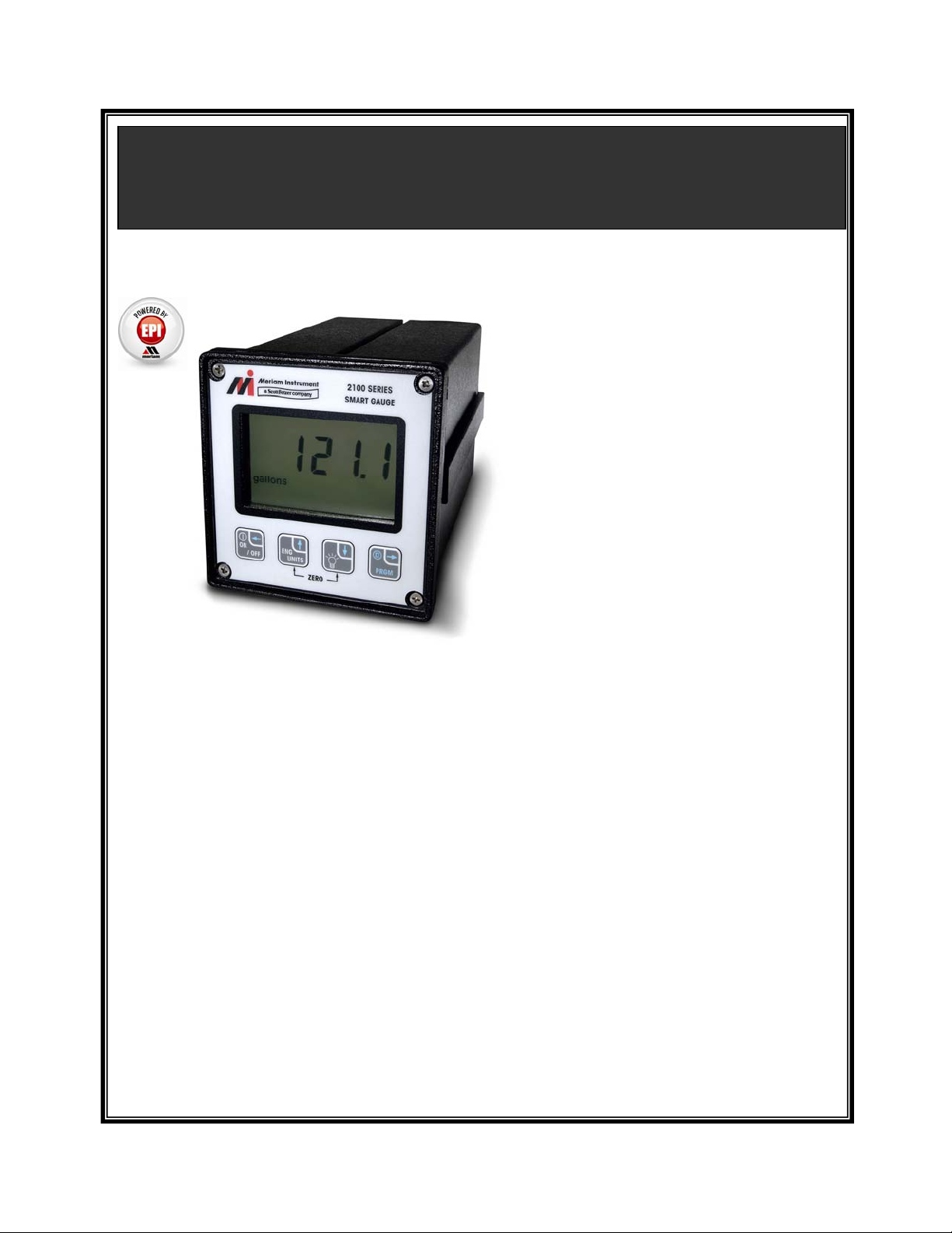
M2110L SMART LEVEL GAUGE
OPERATING INSTRUCTIONS
The Battery model is powered by its internal lithium batteries only. This model does not provide
any outputs or RS-232 communications.
SetPoint and Current Loop models have outputs that can be used for control or
indicating/recording functions. Both models also have RS-232 communications capability. In
addition to configuring the gauge, the RS-232 port can be used to monitor and log the measured
level/pressure data and output status. It can also be used as part of a control system with digital
capabilities.
The SetPoint model provides two SPDT relay outputs with adjustable deadband. This
configuration provides normally open or normally closed contact operation for fail-safety.
Switching SetPoint can be set from 0 to +120% of the full scale level/pressure range. The
SetPoint model is powered by 115/230 VAC, or 24VDC.
The Current Loop model provides a 4 to 20 mA output, and is intended to be used as a level
transmitter on a three or four wire loop. Zero and span are set through user-programmable
registers, from 0 to +120% of the full scale pressure range. The output is capable of normal and
reverse action. The Current Loop model is powered by 24VDC only.
Meriam’s M2110L Smart Level Gauge is
a microprocessor-based pressure sensing
device with algorithms to calculate level.
The various sensors provide dip- tube
bubbler accommodation, or direct head
level measurements. Three configurations are available: Battery, SetPoint,
and Current Loop models.
All models are programmable through the
front keypad, to allow configuration of
the gauge. The user’s program
information is stored in non-volatile
memory, and is retained when the power
to the gauge is removed. SetPoint and
Current Loop models can also be
configured through the RS-232 serial
communication connection.
i
Page 2

9R143 Dated 3/2011
Table of Contents
LEVEL DISPLAY.......................................................................................................................... 1
SAFETY WARNINGS................................................................................................................... 2
CERTIFICATION/SAFETY/WARNINGS ................................................................................... 3
KEYPAD FUNCTIONS:................................................................................................................ 4
PROGRAMMABLE REGISTER OVERVIEW ............................................................................ 6
PROGRAMMABLE REGISTER QUICK REFERENCE............................................................. 6
ENGINEERING UNITS................................................................................................................. 7
ZERO REFERENCE................................................................................................................. ..... 8
P0 – LOCKOUT CODE ................................................................................................................. 9
P1 – TIMEOUT VALUE.............................................................................................................. 10
P2 – DAMP RATE ....................................................................................................................... 11
P3 – RESIDUAL HYDROSTATIC PRESSURE......................................................................... 12
P4 – FULL TANK HYDROSTATIC PRESSURE ......................................................................14
P5 – SETPOINT OPTIONS.......................................................................................................... 15
P6 and P7 – SETPOINT (SET1 and SET2)................................................................................. 16
P8 – DEADBAND........................................................................................................................ 17
P9 – TANK CYLINDRICAL CAPACITY.................................................................................. 18
P10 – TANK ENDS CAPACITY................................................................................................. 19
P11 – TANK TYPE......................................................................................................................20
LOCKOUT CODE PROMPT....................................................................................................... 21
SERIAL PORT SERVICE............................................................................................................ 22
ERROR CODES........................................................................................................................... 24
INSTALLATION AND WIRING................................................................................................ 25
PRODUCT SPECIFICATIONS................................................................................................... 28
SERVICE & CALIBRATION...................................................................................................... 30
ii
Page 3

9R143 Dated 3/2011
LEVEL DISPLAY
Indicators
During normal operation, the gauge displays the level value in large numerals, and the bottom of the
display shows the current Engineering Unit. The top of the display will show PRGM when the gaug e is in
Program Mode (flashing when “view only”). For SetPoint models, the top of the display will show
SET1/SET2 to indicate activated outputs (or corresponding register opened in Program Mode). For
Current Loop models, the top of the display will show 4-20mA when the output is enabled (or
corresponding register opened in Program Mode).
Performance
The M2110L Smart Level Gauge retrieves analog data from its pressure sensor, and performs an analog-to-
digital (A/D) conversion for microprocessor-based data handling. The rate of A/D conversion will
typically be between 9 to 13 conversions per second, depending on the various operating conditions.
To make the display easier to read, only every fourth sample is updated on the display. (This results in a
display update rate of about 3 updates per second.) The internal calculations, outputs, and serial interface
are updated at the full conversion rate.
Resolution
The Smart Gauge has a 4½ digit display. The resolution of the data (decimal point positioning) is defined
by the range and sampling process. The resultant full scale display and data resolution is summarized in
the table below. Note that since the Smart Level Gauge display is primarily user-scaled to level units, the
full scale and resolution depends on the scale. If a specific value will not fit on the 4½ digit display,
however, the auto-range feature will decrease the resolution to allow the value to fit the display (for
example, increasing past 199.99 becomes 200.0). The auto-range feature restores the decimal resolution
with a built-in deadband of 5 display counts (for example, 200.0 must drop to 199.95 before the two-digit
decimal resolution is restored).
Note that the full scale display indication during power-up will not necessarily have the same decimal
resolution found during actual level monitoring.
1
Page 4
9R143 Dated 3/2011
SAFETY WARNINGS
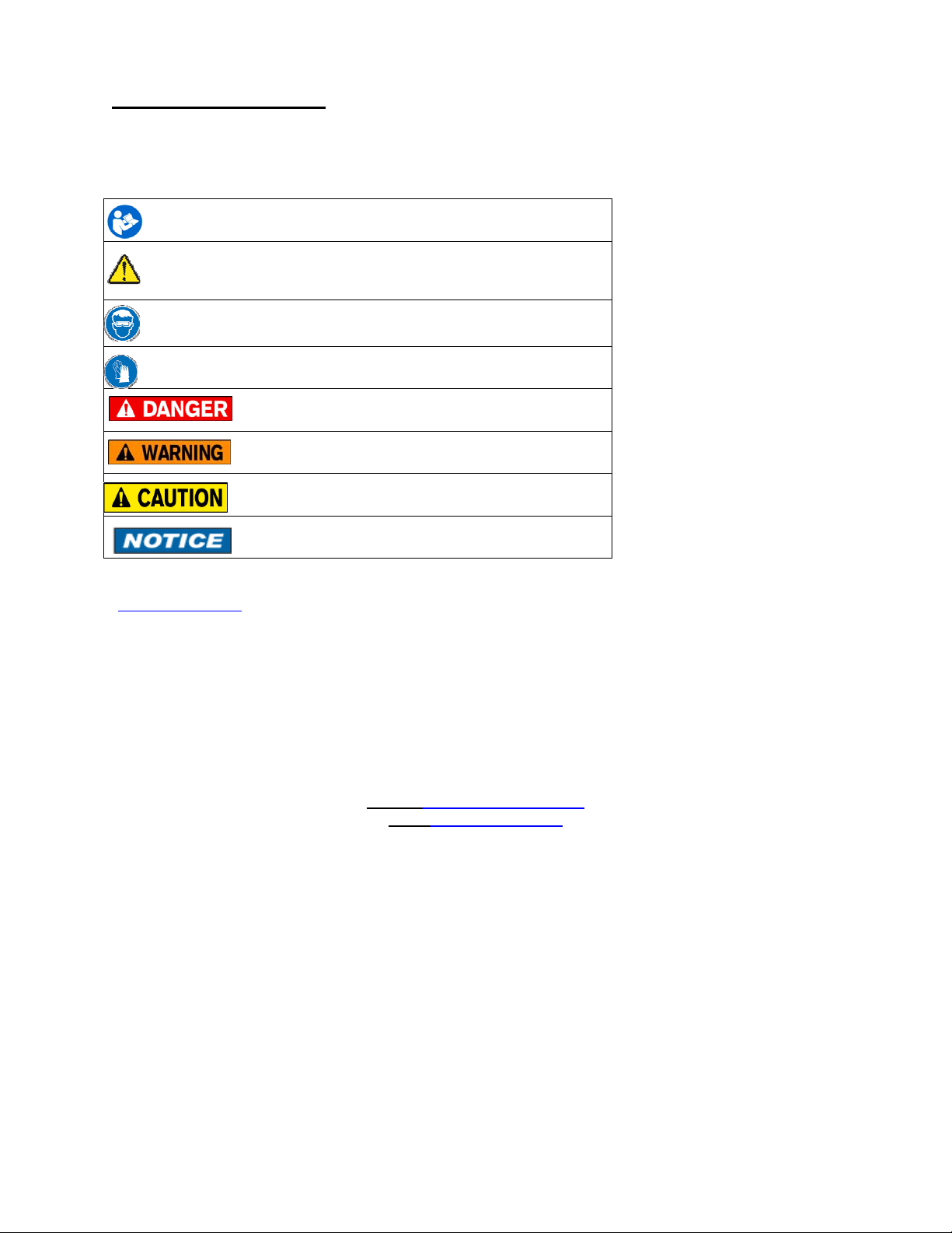
The table below defines the safety symbols, signal words and corresponding safety messa ges used in the
manual to identify potential hazards and are intended to warn persons about hazards that could result in
personal injury or equipment damage.
This is the Read Instruction Manual symbol. This symbol indicates
h that you must read the instruction manual.
This is the Safety Alert symbol. This symbol indicates a WARNING.
Warnings alert you to actions that can cause personal injury or pose a
physical threat. Please read these carefully.
This is the Safety Glasses symbol. This symbol indicates that you must
wear approved safety glasses during the task.
This is the Safety Gloves symbol. This symbol indicates that you must
wear approved safety gloves during the task.
Indicates a potentially hazardous situation which, if not
avoided, will result in death or serious injury.
Indicates a potentially hazardous situation which, if not
avoided, could result in death or serious injury.
Indicates a potentially hazardous situation which, if not
avoided, could result in minor or moderate injury.
Indicates information essential for proper product
installation, operation or maintenance.
Information in this document is subject to change without notice. Check the Meriam web site
(www.meriam.com
For customer assistance please call your local Meriam representative or Meriam di.0
) for the latest manual revision.
Meriam Process Technologies
10920 Madison Avenue
Cleveland, Ohio 44102
Telephone: (216) 281-1100
Fax: (216) 281-0228
E-mail: meriam@meriam.com
Web: www.meriam.com
2
Page 5

9R143 Dated 3/2011
CERTIFICATION / SAFETY / WARNINGS
Fire/Explosion Hazard. This instrument is not intrinsically safe. DO NOT use or
service in areas that may contain flammable gas or vapors, combustible dusts or
ignitable fibers where an unintended spark can cause a fire/explosion.
Do not exceed the Pressure Limits listed in the Specifications section of this
manual. Failure to operate within the specified pressure limit could result in
death or serious injury.
Do not exceed the Maximum Input Voltage listed under “Input Power” in the Specification section
of this manual
Do not exceed the Switch Rating listed under “I/O” in the Specifications section of this manual.
Disconnect power before servicing.
Substitution of components may impair operation and safety.
3
Page 6
9R143 Dated 3/2011
/
KEYPAD FUNCTIONS:
The keys on the front panel perform multiple functions. Their function differs depending on whether the gauge is in
Measure Mode or Program Mode.
• Measure Mode is the normal operating mode for measuring and displaying level. This mode is always
default after power-up or reset.
• Program Mode is used to configure the various options of the gauge. This mode is denoted by a PRGM
indicator on the display.
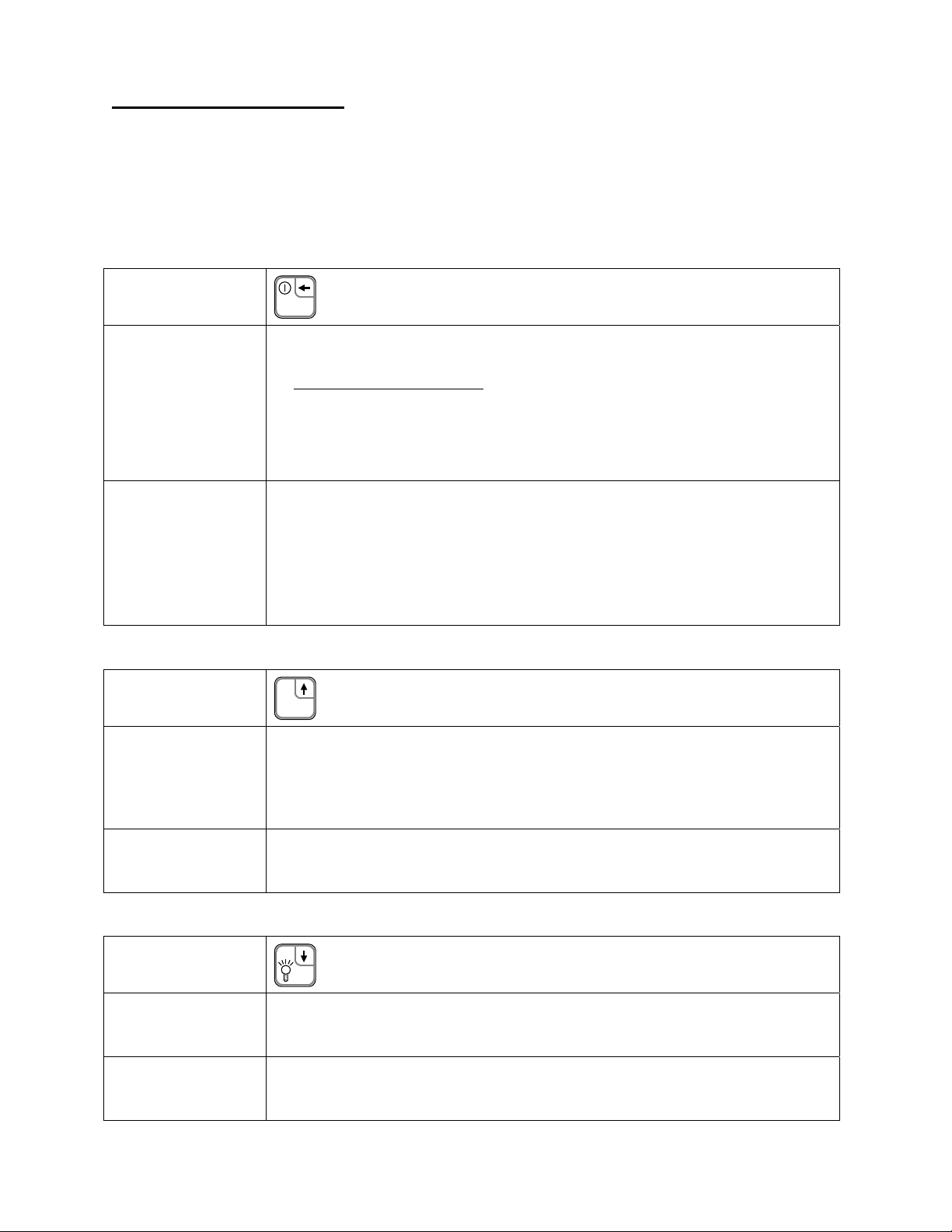
ON/OFF /
Backspace Key
ON
Document Symbol: (Backspace←)
OFF
Measure Mode
Program Mode
ENG UNITS/Up
Arrow Key
Measure Mode
• Battery models: Toggles the gauge ON and OFF.
• SetPoint and Current Loop models: “Resets” the gauge.
Sequence of power-up or reset
1. Display test is performed (all segments of the LCD display are turned on).
2. Firmware revision is displayed.
3. Full scale (programmed level) is displayed in the last Engineering Unit used.
4. All prior register values are restored and activated.
5. Measure Mode displays level in the last Engineering Unit used.
Backspace function:
From Program Mode, this key will exit to Measure Mode.
When editing a register, this key is used to abort a programming operation and exit the
register without making any changes.
When editing a multi-digit value, each key press will backup one digit, until finally
exiting the register.
ENG
UNITS
Document Symbol: (Up↑)
Allows the Engineering Units to be changed (see page 7). During Engineering Unit
selection, the current unit indicator remains solid, and the “new” unit indicator is
flashing. Scrolling through the available units is done by pressing the Up↑ or Down↓
keys. The flashing unit is selected using the PRGM/Enter→ key, or the process may be
aborted by using the Backspace← key.
Program Mode
(and EU Selection)
Scroll up function. Scrolls up through the available programmable registers. Once a
register is opened, this key allows editing by scrolling up through the values in the
register.
Backlight/Down
Arrow Key
Measure Mode
Program Mode
(and EU Selection)
Toggles the display Backlight on and off. Note that the default Backlight status for the
Battery model is OFF to conserve battery life. The other models will retain the prior
Backlight status as default.
Scroll down function. Scrolls down through the available programmable registers. Once
a register is opened, this key allows editing by scrolling down through the values in the
register.
Document Symbol: (Down↓)
4
Page 7
9R143 Dated 3/2011
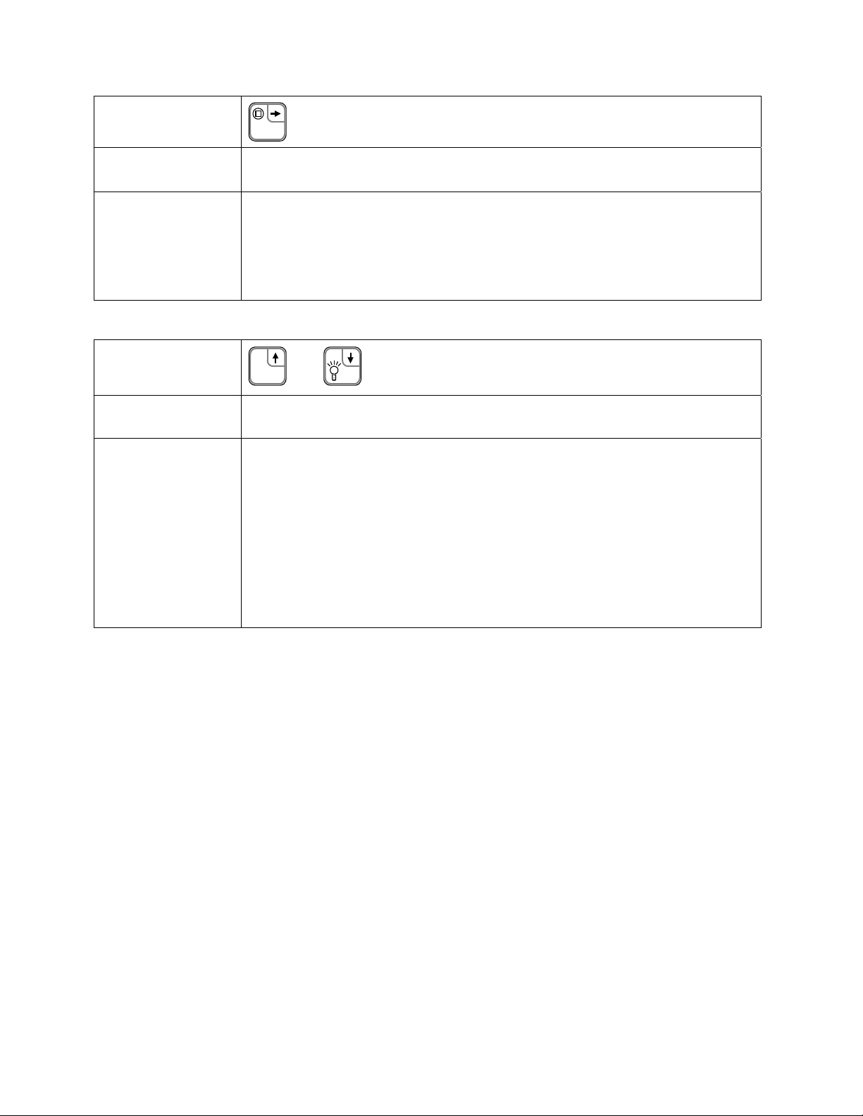
PRGM/Enter Key
Measure Mode
(and EU Selection)
Program Mode
Re-ZERO Key
Measure Mode
Program Mode
(and EU Selection)
PRGM
Selects Program Mode, which allows access to the programmable registers. This key is
also used to accept a new Engineering Unit selection.
Opens the selected programmable register for editing.
When the desired value is displayed, pressing the PRGM/Enter→ key accepts and
stores the value, and closes the register.
When editing a multi-digit value, each key press will accept the current digit and proceed
to the next, until finally accepting the complete value and closing the register.
ENG
UNITS
In Measure Mode, pressing the Up↑ and Down↓ keys at the same time resets the zero
reference of the gauge (see page 8).
In Program Mode, for convenience, this function will reset the current value to default.
For example, in Program Mode (but before opening a register), this function
Document Symbol: (PRGM/Enter→)
Document Symbol: (Up↑ and Down↓)
+
will reset the register scroll to P0.
After opening a register for editing, this function will reset the register’s data
value to default (typically 0).
Similarly, when selecting a new Engineering Unit, this function will reset the
selection to the first unit (gallons).
Note that even when using this “reset” function, the PRGM/Enter→ key must be
pressed to accept the new value (this allows for further editing after reset of the value).
5
Page 8
9R143 Dated 3/2011
PROGRAMMABLE REGISTER OVERVIEW
All M2110L Smart Level Gauges have programmable registers that allow the gauge to be configured to fit the level
measurement application. Programmable registers are numbered P0 through P11. Each register con tro ls a specific
aspect of the gauge’s performance.
Beginning on page 9 is a description of all programmable registers, and instructions for their use. Each register is
found on all M2110L Smart Level Gauge models, and performs the same function described for all models, except
as noted otherwise.
Px
P0
P1
P2
P3
P4
P5
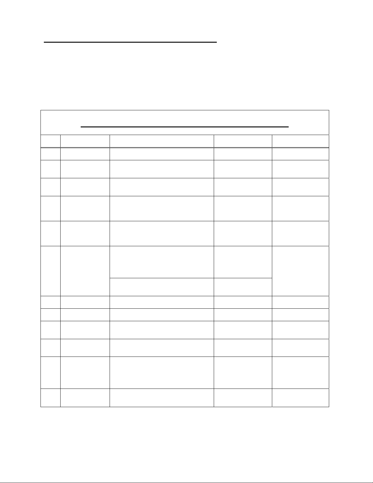
PROGRAMMABLE REGISTER QUICK REFERENCE
Name Description Value Range Notes
Lockout Code Lockout for security. 00 to 99 00 = Disabled.
Timeout Automatic shutoff in minutes of keypad
inactivity.
Damp Rate Exponential damping time in seconds. 0.1, 0.2, 0.5, 1, 2, 5,
Residual
Hydrostatic
Pressure
Full Tank
Hydrostatic
Pressure
SetPoint Options
Identifies the unmeasured or added
hydrostatic pressure due to piping
configurations.
The pressure created by a full column
of fluid from the floor of the tank to the
top of the maximum level measured.
SetPoint Model: defines which relay
outputs are active.
Current Loop Model: defines the status
of the 4 - 20 mA output.
0 (disabled), 1, 2, 5,
10, 15, 25
10, 15, 25, 50
-9,999 to +9,999
O @ 20ºC.
inH
2
0 to 9,999 (Keypad)
0 to 19,999 (Serial)
0 = Disabled.
1 = SET1 only.
2 = SET2 only.
3 = Both enabled.
0 = 4-20 disabled
1 = 4-20 enabled
Battery model only.
0.1 = No Damping.
+Val: Dip Tube
- Val: Direct Head
Pressure in inH
@20°C.
Not found on
Battery model.
O
2
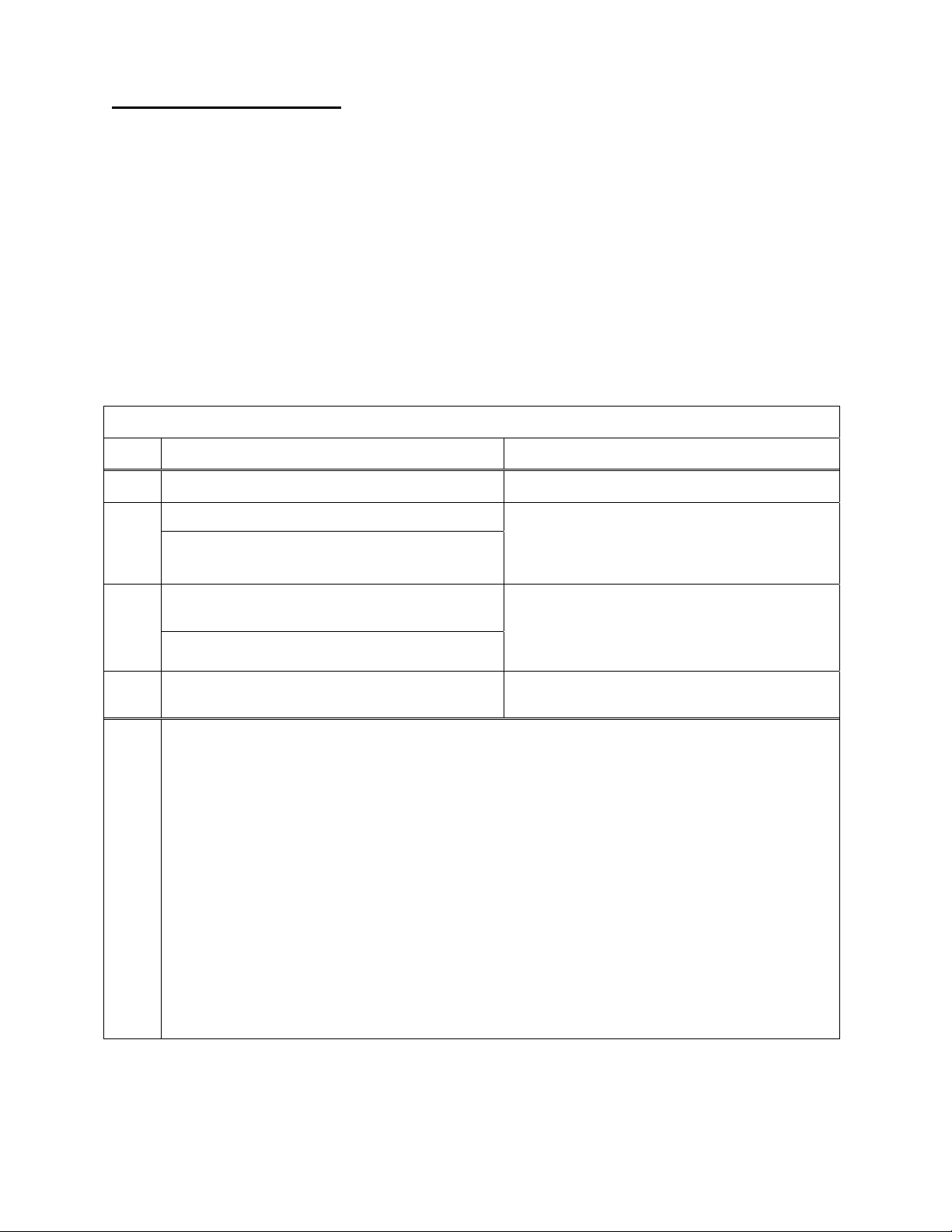
P6
P7
P8
P9
P10
P11
SET1 Controls SET1 relay or 4.00 mA value. –20% to +120% FS User defined value.
SET2 Controls SET2 relay or 20.0 mA value. –20% to +120% FS User defined value.
Deadband Sets the amount of deadband in percent
of full scale for relays.
Tank Cylindrical
Capacity
Tank Ends
Capacity
Tank Type Identifies type of tank. 0 = Linear/Vertical
The capacity, in Engineering Units, of
only the cylindrical portion of the tank.
The capacity, in Engineering Units, of
only the dished ends of a hori zont al
cylindrical tank (includes both ends).
Or, total capacity for spherical tanks.
0 (disabled), 0.1,
0.2, 0.5, 1, 2, 5, 10%
0 to 9,999 (Keypad)
0 to 19,999 (Serial)
0 to 9,999 (Keypad)
0 to 19,999 (Serial)
1 = Non Linear
SetPoint model
only.
P9 = 0 for spherical
tanks.
P10 = 0 for linear
tanks, or cylindrical
tanks with flat ends.
6
Page 9
9R143 Dated 3/2011
ENGINEERING UNITS
The following Engineering Units are available on the M2110L Smart Level Gauge:
1. Gallons
2. Pounds
3. Cubic Feet
4. Liters
5. Percent
6. Kilograms
7. Cubic Meters
8. InH2O – Inches of Water Column (density reference temperature: 20°C)
9. User Units – User Defined Units
STEP BY STEP: CHANGING ENGINEERING UNITS
Step Action Display
1
2
3
4
Notes
Gauge should be in the normal Measure Mode. Normal Level Display.
Press the ENG UNITS (Up↑) key.
If the lockout is active, the gauge will now prompt for entry of
the lockout code. Refer to “STEP BY STEP: ENTERING A
LOCKOUT CODE (When Prompted)” on page 21.
Press the Up↑ or Down↓ keys repeatedly to scroll
to the desired Engineering Unit.
The Zero function (Up↑ and Down↓) will reset the scroll to the
first unit and allow selection to continue.
Press the PRGM/Enter→ key when the desired
unit is flashing.
1. When scrolling through Engineering Units, User Units are denoted by all units flashing.
2. In Measure Mode, User Units are denoted by no Engineering Unit indicators shown on the bottom
of the display.
3. Changing the Engineering Unit will automatically update the SetPoint and Capacity registers as
appropriate (refer to the Automatic Update section on pages 16, 18, and 19 for further explanation).
4. If programmed in a volumetric unit (gallons, liters, feet
to other volumetric units using the ENG UNITS (Up↑) key, and likewise for mass units (pounds,
kilograms). However, the Smart Level Gauge will not convert between volumetric units, mass
units, and/or user units. Percent (%) and InH
programmed.
Current Engineering Unit1 indicator flashes.
The current Engineering Unit indicator remains
solid since it is active, and the unit to be selected
flashes as the list is scrolled.
The display switches to the new Engineering Unit
and returns to Measure Mode.
3
, meter3), the Smart Level Gauge will convert
O are available regardless of what unit was
2
2
5. At any time, the Backspace← key will abort the process and return to Measure Mode.
6. If there is no keypad activity for approximately 1 minute, the operation is aborted and the gauge
returns to Measure Mode unchanged.
7
Page 10
9R143 Dated 3/2011
ZERO REFERENCE
Zeroing the gauge consists of accepting the current applied pressure value as the zero pressure reference. To set the
zero reference pressure, all pressure sources should be disconnected from the gauge, and its temperature should be
stable.
The Smart Level Gauge displays tank level as a function of the applied pressure. This pressure is linearly offset
from the zero reference value, before applying the tank level calculations.
AFFECT ON OUTPUTS
The SetPoint and Current Loop outputs are calculated based on the displayed level. Since re-zeroing the
gauge may change the displayed level, the outputs may change accordingly. For safety purposes, if the
outputs are active (defined by register P5; see page 15), an extra step is required to warn the operator and
confirm the desired action. For clarity, both scenarios are described below, step-by-step.
FACTORY ZERO
The “Factory Zero” can be restored through the serial port service only (SetPoint and Current Loop mode ls
only). This is the value set during calibration of the sensor, and is typically 0.0.
RANGE CHECK
The Smart Gauge can be zeroed only when the applied pressure is within ±5% of sensor full scale. If the
applied pressure is greater than 5% of full scale, an error code will be displayed when zeroing is attempted.
STEP BY STEP: RE-ZEROING THE GAUGE (Disabled Outputs, P5=0)
Step Action Display
1
2
Gauge should be in normal Measure Mode, with
applied pressure ready for zeroing (typically vented).
Press the Up↑ and Down↓ keys simultaneously.
If the lockout is active, the gauge will now prompt for entry of the
lockout code. Refer to “STEP BY STEP: ENTERING A
LOCKOUT CODE (When Prompted)” on page 21.
Normal level display, near 0.0 (or offset from the
Residual Hydrostatic Pressure, P3).
The display will flash “0000” several times while
the new zero is taken, and then return to Measure
Mode with the new zero activated.
WHEN OUTPUTS ARE ACTIVE (P5>0) ...
1
2
3
Gauge should be in normal Measure Mode, with
applied pressure ready for zeroing (typically vented).
Press the Up↑ and Down↓ keys simultaneously.
If the lockout is active, the gauge will now prompt for entry of the
lockout code. Refer to “STEP BY STEP: ENTERING A
LOCKOUT CODE (When Prompted)” on page 21.
Press PRGM/Enter→ before the countdown
1
expires
. This acknowledges the warning.
Normal level display, near 0.0 (or offset from the
Residual Hydrostatic Pressure, P3).
The display will begin countdown from
“0005” to “0000”.
The display will again countdown from
“0005” to “0000”.
SetPoint and Current
Loop models only
4
Notes
Press ZERO again (Up↑ and Down↓) before the
countdown expires
1. During steps 2 or 3, if the countdown expires, the gauge will return to Measure Mode un chan ged.
2. During steps 2 or 3, the Backspace← key will abort the process and return to Measure Mode.
3. The zero reference value is snapshot immediately when the ZERO keys are pressed. This temporarily
stored value is accepted once the zeroing process is complete (or discarded if not completed).
1
. This confirms the zero action.
The display will flash “0000” several times while
the new zero is taken.
8
Page 11

9R143 Dated 3/2011
P0 – LOCKOUT CODE
This feature provides security in the Smart Gauge. It is designed to prevent unauthorized personnel from tampering
with or inadvertently changing the configuration of the gauge. The lockout is con trolled by a 2-digit setting in the
P0 register. Once a lockout code is entered, the gauge will prompt for the lockout code before allowing any changes
(similar to a “password”). Changes include Engineering Unit selection, re-zeroing, or entering Program Mode.
Following an operator action, if the correct code (password) is not entered when prompted, an error message is
briefly displayed. If the operator action was changing Engineering Units or re-zero the gauge, the gauge will simply
return to normal Measure Mode operation, without accepting any change. If the operator action was entering
Program Mode, the gauge will enter a “view-only” status (see page 21), denoted by the PRGM indicator flashing.
In Program Mode (and during lockout code prompting), the register value is shown as “L xx” to assist in
identifying the register. The “L ” indicates “Lockout”, and “xx” will consist of the current value.
All Models
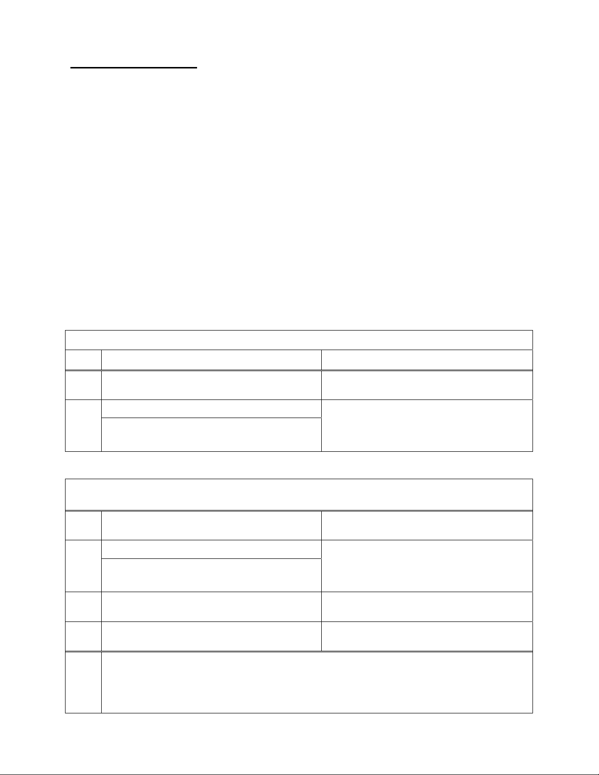
QUICK REFERENCE: P0, LOCKOUT CODE
Px
Name Description Value Range Notes
P0 Lockout Code Lockout for security. 00 to 99 00 = Disabled.
STEP BY STEP: P0, LOCKOUT CODE
Step Action Display
1
2
3
4
5
6
7
Notes
Gauge should be in the normal Measure Mode. Normal Pressure Display.
Press the PRGM/Enter→ key.
If the lockout is active, the gauge will now prompt for entry of
the lockout code. Refer to “STEP BY STEP: ENTERING A
LOCKOUT CODE (When Prompted)” on page 21.
Press PRGM/Enter→ again, to open the register.
Press the Up↑ or Down↓ keys repeatedly to scroll
to the desired numeric value for the flashing digit.
The Zero function (Up↑ and Down↓) will reset the entire
register to 00 and allow editing to continue.
Press the PRGM/Enter→ key to accept the digit.
Repeat steps 4 and 5 for the second digit. The complete 2-digit value will be accepted, and
Press the Backspace← key to activate the lockout
and return to Measure Mode.
1. After step 2, the Backspace← key will abort the process and return to Measure Mode.
2. After steps 3 or 4, the Backspace← key will abort the current digit and close the register (since it is
the first digit).
3. After step 5, the Backspace← key will abort the current digit and backup to the first digit. Another
Backspace← will abort the process and close the register.
4. After step 6, the PRGM/Enter→ key will again open the register for edit.
5. During any programming operation, if there is no keypad activity for approximately 1 minute, the
operation is aborted and the gauge returns to Measure Mode unchanged.
The PRGM annunciator shows at the top of the
display, and the display shows the register name
“P0”.
The display will show “L xy” with the first digit
flashing for edit (indicating L
“L _x”, where “_” is the digit being edited
(flashing).
The next digit begins flashing for edit.
the register is closed (display shows P0 for
selection).
Normal Pressure Display.
ockout Code xy).
9
Page 12

9R143 Dated 3/2011
P1 – TIMEOUT VALUE
This register sets the length of time (in minutes) for automatic shutoff. The Battery model will automatically shutoff
if there is no keypad activity for this length of time. This feature can be disabled by selecting 0 in the register,
which allows the gauge to remain on indefinitely, or until the ON/OFF key is pressed (battery life may be reduced).
During programming, the choices found in the register correspond to the actual timeout values, in minutes.
Battery Models Only
QUICK REFERENCE: P1, TIMEOUT
Px
Name Description Value Range Notes
P1 Timeout Automatic shutoff in minutes of
keypad inactivity.
0 (disabled),
1, 2, 5, 10, 15, 25
Battery model
only.
STEP BY STEP: P1, TIMEOUT
Step Action Display
1
2
Gauge should be in the normal Measure Mode. Normal Pressure Display.
Press the PRGM/Enter→ key.
If the lockout is active, the gauge will now prompt for entry of
the lockout code. Refer to “STEP BY STEP: ENTERING A
LOCKOUT CODE (When Prompted)” on page 21.
The PRGM annunciator shows at the top of the
display, and the display shows the register name
“P0”.
3
4
5
6
7
Notes
Press the Up↑ or Down↓ keys repeatedly to scroll
to the desired register.
The Zero function (Up↑ and Down↓) will reset the scroll to P0
and allow selection to continue.
Press PRGM/Enter→ to open the register.
Press the Up↑ or Down↓ keys repeatedly to scroll
to the desired register value.
The Zero function (Up↑ and Down↓) will reset the scroll to
default and allow editing to continue.
Press the PRGM/Enter→ key to accept the desired
value.
Press the Backspace← key to activate the register
setting and return to Measure Mode.
1. After steps 2 and 3, the Backspace← key will abort the process and return to Measure Mode.
2. After steps 4 and 5, the Backspace← key will abort the edit and close the register.
3. After step 6, the PRGM/Enter→ key will again open the register for edit.
4. During any programming operation, if there is no keypad activity for approximately 1 minute, the
operation is aborted and the gauge returns to Measure Mode unchanged.
Display shows “P1”.
The display shows the current value.
All available choices are scrolled.
(Choices indicate actual Timeout in seconds.)
The value is accepted, and the register is closed.
Display shows “P1”.
Normal Pressure Display.
10
Page 13

9R143 Dated 3/2011
P2 – DAMP RATE
The Smart Gauge has a selectable damp rate, which is used to stabilize the display for applications with a pulsating
pressure source. The damp rate setting is roughly the length of time it will take for the gauge to ramp from one
stable pressure to another. The ramping is exponential, changing at a slower rate as the final value is approached.
The “time constant” of the exponential equation is roughly one-fifth of the damp rate setting. This means that the
damped value will be roughly 63% of final value after a time equal to one-fifth of the register setting. The value
will be roughly 86% of final value after a time equal to two-fifths of the register setting.
The damping function only affects the displayed value (LCD display and RS232 data); it does not
of the SPDT relays, the 4 to 20 mA outputs, or the response to over-pressure (“OP” indication).
All Models
affect the action
QUICK REFERENCE: P2, DAMP RATE
Px
Name Description Value Range Notes
P2 Damp Rate Exponential damping time in
seconds.
0.1, 0.2, 0.5, 1, 2,
5, 10, 15, 25, 50
0.1 = No
Damping.
STEP BY STEP: P2, DAMP RATE
Step Action Display
1
2
3
4
5
6
7
Notes
Gauge should be in the normal Measure Mode. Normal Pressure Display.
Press the PRGM/Enter→ key.
If the lockout is active, the gauge will now prompt for entry of
the lockout code. Refer to “STEP BY STEP: ENTERING A
LOCKOUT CODE (When Prompted)” on page 21.
Press the Up↑ or Down↓ keys repeatedly to scroll
to the desired register.
The Zero function (Up↑ and Down↓) will reset the scroll to P0
and allow selection to continue.
Press PRGM/Enter→ to open the register.
Press the Up↑ or Down↓ keys repeatedly to scroll
to the desired register value.
The Zero function (Up↑ and Down↓) will reset the scroll to
default and allow editing to continue.
Press the PRGM/Enter→ key to accept the desired
value.
Press the Backspace← key to activate the register
setting and return to Measure Mode.
1. After steps 2 and 3, the Backspace← key will abort the process and return to Measure Mode.
2. After steps 4 and 5, the Backspace← key will abort the edit and close the register.
3. After step 6, the PRGM/Enter→ key will again open the register for edit.
4. During any programming operation, if there is no keypad activity for approximately 1 minute, the
operation is aborted and the gauge returns to Measure Mode unchanged.
The PRGM annunciator shows at the top of the
display, and the display shows the register name
“P0”.
Display shows “P2”.
The display shows the current value.
All available choices are scrolled.
(Choices indicate actual damp rate in seconds.)
The value is accepted, and the register is closed.
Display shows “P2”.
Normal Pressure Display.
11
Page 14

9R143 Dated 3/2011
P3 – RESIDUAL HYDROSTATIC PRESSURE
The M2110L Smart Level Gauge will correctly measure level when used with a dip tube or as a direct-head pressure
reading of the tank’s fluid column. Register P3 is used to describe the unmeasurable pressure below the dip tube, or
the additional pressure created by a “dead leg” in the direct-head piping. This register must be specified in Inches of
Water Column at 20
o
C reference.
All Models
QUICK REFERENCE: P3, RESIDUAL HYDROSTATIC PRESSURE
Px
Name Description Value Range Notes
P3 Residual
Hydrostatic
Pressure
Dip Tube Application
The P3 register specifies the pressure created by the
height of the fluid below the dip tube to the bottom of the
tank. The volume in the tank below this point cannot
be measured! To compensate for this unmeasured
volume (optional), enter this register as a positive value.
Direct Head Measurement
Identifies the Pressure lost or
added due to piping
configurations.
The P3 register specifies the pressure caused by the
vertical “dead leg” of the piping to the gauge. This is
additional pressure applied to the gauge that is not
due to fluid volume in the tank. To compensate for
this pressure, enter this register as a negative value.
-9999 to +9999
inH2O @ 20ºC.
+Val:Dip Tube
-Val: Dir.Head
Note: The Low Pressure side is connected to the tank top on pressurized tanks only, as shown, using a differential
pressure, non-isolated model (DN) Smart Level Gauge. It is recommended that a gauge-pressure, isolated sensor
model (GI) Smart Level Gauge be used whenever possible for measuring fluid level (vented tank).
The differential pressure, non-isolated sensor (required for pressurized tanks) is compatible with clean, dry, noncorrosive gases only. This will work without modification in most bubbler system applications. However, when
corrosive liquids or vapors are in the tank, a diaphragm seal will be needed on the high and low pressure lines (or
on the high pressure line in a direct head pressure system). Consult the factory for information on diaphragm seal
selection, limitations, and the effects on overall gauge performance.
STEP BY STEP: P3, RESIDUAL HYDROSTATIC PRESSURE
Step Action Display
1
2
Gauge should be in the normal Measure Mode. Normal Pressure Display.
Press the PRGM/Enter→ key.
If the lockout is active, the gauge will now prompt for entry of
the lockout code. Refer to “STEP BY STEP: ENTERING A
LOCKOUT CODE (When Prompted)” on page 21.
The PRGM annunciator shows at the top of the
display, and the display shows the register name
“P0”.
12
Page 15

9R143 Dated 3/2011
3
4
5
6
7
8
Press the Up↑ or Down↓ keys repeatedly to scroll
to the desired register.
The Zero function (Up↑ and Down↓) will reset the scroll to P0
and allow selection to continue.
Press PRGM/Enter→ to open the register.
Press the Up↑ or Down↓ keys repeatedly to scroll
to the desired numeric value for the flashing digit.
The Zero function (Up↑ and Down↓) will reset the entire
register to 0000 and allow editing to continue. The decimal
point and negative sign will not be affected, and the same digit
will be flashing.
Press the PRGM/Enter→ key to accept the digit.
Repeat steps 5 and 6 for the all remaining digits.
The Backspace← key will backup one digit at a time, or abort
and close the register if the first digit is flashing.
The PRGM/Enter→ key will accept one digit at a time, moving
to the next, or accept the complete value and close the register
after the decimal point edit.
Press the Up↑ or Down↓ keys repeatedly to scroll
to the desired decimal point position, and to select
positive/negative.
If the Zero function (Up↑ and Down↓) is used during decimal
point editing, it will still reset the register’s value to 0000, and
not affect the decimal point position or negative sign.
Display shows “P3”.
The display will show the current value, with the
first zero flashing for edit.
“_xxx”, where “_” is the digit being edited.
The next digit begins flashing for edit.
After Enter→ when the last digit is flashing, the
decimal point flashes for edit.
Please read carefully note 4 below.
Decimal point moves accordingly.
Please read carefully note 4 below.
Negative Sign activates and de-activates when the
decimal point sequence is scrolled through
completely.
9
10
Notes
Press the PRGM/Enter→ key to accept the
complete value.
Press the Backspace← key to activate the register
The value is accepted, and the register is closed.
Display shows “P6” or “P7”.
Normal Pressure Display.
setting and return to Measure Mode.
1. Preceding/Trailing zeroes are determined by where the user places the decimal point. When opening
a register, the value is always shown padded with trailing zeroes.
2. Only 4 digits are available for editing (the ½ digit is not provided), plus the decimal point and
negative sign (negative is not applicable to register P4). This limits keypad value entries to ±9,999,
and also limits the available decimal point resolution (depending on the magnitude of the value). The
serial interface provides much more flexibility.
3. After steps 2 and 3, the Backspace← key will abort the process and return to Measure Mode.
4. The display does not have a physical decimal point that can be illuminated in the least significant
position (to the right of all digits on the display). Thus, if the decimal point is in that particular
position, there will be no decimal point blinking (which may be confusing). When scro lling through
the decimal point selection, it is important to take note that none blinking is a viable setting, and will
be seen in the scrolling sequence.
5. After step 9, the PRGM/Enter→ key will again open the register for edit.
6. During any programming operation, if there is no keypad activity for approximately 1 minute, the
operation is aborted and the gauge returns to Measure Mode unchanged.
13
Page 16

9R143 Dated 3/2011
P4 – FULL TANK HYDROSTATIC PRESSURE
This register is used by the gauge to draw a relationship between measured static pressure and actual level in volume
or mass units. This register must be set to the pressure created by a FULL COLUMN of vertical fluid in the tank, in
inches of water column at 20ºC reference temperature.
1
To calculate this value, multiply the specific gravity
the floor
convert the resultant pressure value to inches of water column at 20ºC reference (for example, to convert PSI to
InH
Note that the P4 value is not affected by installation type (bubbler system or direct head measurement). The value is
calculated in the same way for either system. The residual pressure (page 12) is not added to or subtracted from
this value.
2
of the tank to the top of the maximum level to be measured. Then, using the appropriate scale factor,
O @20ºC, multiply by 27.72978).
2
of the fluid (relative to water at 60°F) by the full distance from
All Models
QUICK REFERENCE: P4, FULL TANK HYDROSTATIC PRESSURE
Px
Name Description Value Range Notes
Full Tank
P4
Hydrostatic
Pressure
The pressure created by a full
column of fluid from the floor of
the tank to the top of the
0 to 9,999 (Keypad)
0 to 19,999 (Serial)
Pressure in
inH2O
@20°C.
maximum level to be measured.
STEP BY STEP: P4, FULL TANK HYDROSTATIC PRESSURE
The process of programming this register is exactly the same as other real-value programmable registers. Please
refer to that procedure on page 12.
1
When the specific volume is known, perform the calculation in a similar manner, but use the inverse of the specific
volume instead of the specific gravity.
2
For non-linear tanks, use the lowest point of the tank when figuring the full distance.
14
Page 17

9R143 Dated 3/2011
P5 – SETPOINT OPTIONS
This register defines the output action for SetPoint and Current Loop models. Note that if an output is disabled by
this register, the SetPoint value in its corresponding register (P6, P7) has no impact. Also note that a SetPoint value
(P6, P7) may be 0.0, which is a viable output setting; thus, in order to disable control action, register P5 should be
used to define the desired action.
In Measure Mode, the indicators “SET1” and/or “SET2” will illuminate when the corresponding relay is energized.
The “4-20mA” indicator will illuminate when the Current Loop output is enabled. In Program Mode, the
indicators “SET1”, “SET2”, and “4-20mA” will illuminate as appropriate to assist when scrolling through the
register’s choices. Note that if P5 is set for active, the outputs will continue to update even in Program Mode,
according to the currently programmed values.
SetPoint & Current Loop Models Only
QUICK REFERENCE: P5, SETPOINT OPTIONS
Px
Name Description Value Range Notes
P5 SetPoint
Options
SetPoint model:
Defines which relay outputs are active.
Current Loop model:
Defines status of the 4-20 mA output.
0 = Disabled.
1 = SET1 only.
2 = SET2 only.
3 = Both enabled.
0 = 4-20 disabled
1 = 4-20 enabled
Not found on
Battery model.
STEP BY STEP: P5, SETPOINT OPTIONS
Step Action Display
1
2
3
4
5
6
7
Gauge should be in the normal Measure Mode. Normal Pressure Display.
Press the PRGM/Enter→ key.
If the lockout is active, the gauge will now prompt for entry of
the lockout code. Refer to “STEP BY STEP: ENTERING A
LOCKOUT CODE (When Prompted)” on page 21.
Press the Up↑ or Down↓ keys repeatedly to scroll
to the desired register.
The Zero function (Up↑ and Down↓) will reset the scroll to P0
and allow selection to continue.
Press PRGM/Enter→ to open the register.
Press the Up↑ or Down↓ keys repeatedly to scroll
to the desired register value.
The Zero function (Up↑ and Down↓) will reset the scroll to
default and allow editing to continue.
Press the PRGM/Enter→ key to accept the value.
Press the Backspace← key to activate the register
setting and return to Measure Mode.
The PRGM annunciator shows at the top of the
display, and the display shows the register name
“P0”.
Display shows “P5”.
The display shows the current value.
All available choices are scrolled.
The value is accepted, and the register is closed.
Display shows “P5”.
Normal Pressure Display.
Notes
1. After steps 2 and 3, the Backspace← key will abort the process and return to Measure Mode.
2. After steps 4 and 5, the Backspace← key will abort the edit and close the register.
3. After step 6, the PRGM/Enter→ key will again open the register for edit.
4. During any programming operation, if there is no keypad activity for approximately 1 minute, the
operation is aborted and the gauge returns to Measure Mode unchanged.
15
Page 18

9R143 Dated 3/2011
P6 and P7 – SETPOINT (SET1 and SET2)
SetPoint & Current Loop Models Only
SetPoint Model
These registers define the pressure points at which the SPDT relays will energize. The relay will energize
when the pressure exceeds its corresponding value, and de -energize when the pressure drops below the
value (minus deadband; see page 17). P6 defines the SET1 relay, and P7 defines the SET2 relay. P6 and
P7 settings are completely independent of each other; either may be greater, less than, or equal to the other.
Current Loop Model
These registers define the 4 to 20 mA output value. P6 (SET1) sets the 4.00 mA output and P7 (SET2) sets
the 20.00 mA output. (Thus, the output “zero” is defined by SET1, and the “span” is defined by SET2 –
SET1.) When the pressure is at the P6 value, the output will be 4.00 mA; when the pressure is at the P7
value, the output will be 20.00 mA. Other pressures provide an output that is linearly scaled between the
two values. For values beyond the defined range, however, the output is limited from 4.00 to 20.38 mA.
The P6 (4 mA) register can be set greater than the P7 (20 mA) re gister, t o create a reverse acting output.
The limits are –20% to +120% full scale, but P6 and P7 cannot be set at equal values.
Data Entry
Refer to the Step by Step table below for detailed instructions.
These registers are entered in the current Engineering Unit used by the gauge. (The current Engineering
Unit is illuminated during edit of these registers.) For example, if the gauge is set to read in gallons, and a
value of 110 is put into the P6 register, the SET1 relay will energize at 110 gallons.
In Program Mode, the indicators “SET1”, “SET2”, and “4-20mA” will illuminate as appropriate to assist
in identifying the register. For example, when scrolling to and/or editing P6, “SET1” will be illuminated,
indicating that SET1 is being edited. Likewise for P7 and “SET2”. Also, “4-20mA” will be illuminated if
the gauge is a Current Loop model, to indicate that the 4-20mA range is being edited.
Automatic Update
If the Engineering Unit is changed in measure mode (see page 7), the value in the P6 and P7 registers will
automatically change to reflect the new Engineering Unit. This allows changing the Engineering Unit in
Measure Mode without affecting the outputs. For the above example, changing the Engineering Unit to
liters will automatically update the P6 register to energize at 416.4 liters, which is equivalent to 110
gallons.
QUICK REFERENCE: P6/P7, SETPOINTS
Px
Name Description Value Range Notes
P6 SET1
P7 SET2
SetPoint model:
Controls SET1 relay.
Current Loop model:
Sets 4.00 mA value.
SetPoint model:
Controls SET2 relay.
–20% to +120%
of Full Scale
–20% to +120%
of Full Scale
User defined
values.
On Current
Loop models,
SET1 cannot
equal SET2.
Current Loop model:
Sets 20.00 mA value.
STEP BY STEP: P6/P7, SETPOINTS
The process of programming this register is exactly the same as other real-value programmable registers. Please
refer to that procedure on page 12.
16
Page 19

9R143 Dated 3/2011
P8 – DEADBAND
This register is found on the SetPoint model only. It sets the adjustable deadband for the SPDT relays. Deadband
can be set to 0%, 0.1, 0.2, 0.5, 1, 2, 5 and 10% of full scale. The relay will energize precisely at the value in its
corresponding P6 and P7 registers on increasing level. The relay will de-energize at a value equal to the
corresponding P6 and P7 register, minus the deadband value, on decreasing level. With a 0% deadband setting, the
relays will energize and reset precisely at the values in the corresponding P6 and P7 registers. During programming,
the choices found in the register correspond to the actual deadband values in percent full scale.
SetPoint Models Only
QUICK REFERENCE: P8, DEADBAND
Px
Name Description Value Range Notes
P8 Deadband Sets the amount of deadband in
percent of full scale for relays.
0, 0.1, 0.2, 0.5, 1,
2, 5, 10% FS
SetPoint model only.
0 = Disabled.
STEP BY STEP: P8, DEADBAND
Step Action Display
1
2
Gauge should be in the normal Measure Mode. Normal Pressure Display.
Press the PRGM/Enter→ key.
If the lockout is active, the gauge will now prompt for entry of
the lockout code. Refer to “STEP BY STEP: ENTERING A
LOCKOUT CODE (When Prompted)” on page 21.
The PRGM annunciator shows at the top of the
display, and the display shows the register name
“P0”.
3
4
5
6
7
Notes
Press the Up↑ or Down↓ keys repeatedly to scroll
to the desired register.
The Zero function (Up↑ and Down↓) will reset the scroll to P0
and allow selection to continue.
Press PRGM/Enter→ to open the register.
Press the Up↑ or Down↓ keys repeatedly to scroll
to the desired register value.
The Zero function (Up↑ and Down↓) will reset the scroll to
default and allow editing to continue.
Press the PRGM/Enter→ key to accept the desired
value.
Press the Backspace← key to activate the register
setting and return to Measure Mode.
1. After steps 2 and 3, the Backspace← key will abort the process and return to Measure Mode.
2. After steps 4 and 5, the Backspace← key will abort the edit and close the register.
3. After step 6, the PRGM/Enter→ key will again open the register for edit.
4. During any programming operation, if there is no keypad activity for approximately 1 minute, the
operation is aborted and the gauge returns to Measure Mode unchanged.
Display shows “P8”, and the “%” annunciator is
illuminated.
The display shows the current value.
All available choices are scrolled.
(Choices indicate actual Deadband in percent of
full scale.)
The value is accepted, and the register is closed.
Display shows “P8”.
Normal Pressure Display.
17
Page 20

9R143 Dated 3/2011
P9 – TANK CYLINDRICAL CAPACITY
The Smart Level Gauge calculates level based on measured hydrostatic pressure, by drawing a relationship between
the full tank hydrostatic pressure (register P4, page 14), and the total capacity of the tank (volume or mass). The
residual pressure (register P3, page 12) and tank type (register P11, page 20) are also considered in the calculations.
The P9 and P10 registers together specify the tank capacity referred to above. The P9 value may be entered in any
desired Engineering Unit, except InH2O (refer to page 7 for available units); User Units and Percent are also
acceptable. The value programmed in P9 depends on the type of tank, as described below:
LINEAR TANK Cylindrical/Flat Ends Cylindrical/Dished Ends Spherical
P9=Volume/mass of the
full tank. (The full volume
is comprised of the entire
cylindrical section.)
P9=Volume/mass of the
full tank. (The full volume
is comprised of the entire
cylindrical section.)
P9=Volume/mass of the
cylindrical portion only.
(Tank capacity minus
dished ends capacity.)
P9=0. (The full volume is
comprised essentially of 2
dished ends, entered in the
P10 register.)
All Models
QUICK REFERENCE: P9, TANK CYLINDRICAL CAPACITY
Px
Name Description Value Range Notes
P9 Tank Cylindrical
Capacity
The capacity, in Engineering
Units, in the cylindrical portion
of the tank only.
0 to 9,999
(Keypad)
0 to 19,999
P9 = 0 for
spherical
tanks.
(Serial)
Automatic Update
If the Engineering Unit is changed in Measure Mode (see page 7), the value in the P9 and P10 registers will
automatically change to reflect the new Engineering Unit. This allows changing the Engineering Unit in Measure
Mode and maintaining a correct level display.
STEP BY STEP: P9, TANK CYLINDRICAL CAPACITY
The process of programming this register is exactly the same as other real-value programmable registers. Please
refer to that procedure on page 12. However, the following notes are specific to the P9 and P10 register:
Notes
1. After completing the P9 or P10 value programming (step 9 on page 13), the gauge will then prompt
for Engineering Unit selection by flashing the current unit. To complete P9 or P10 programming,
proceed with Engineering Unit selection (described on page 7). This selection defines the units that
were programmed into P9 and P10. If the units are not to be changed, you may simply re-enter or
abort the Engineering Unit selection process (page 7).
2. Register P9 and P10 values always represent the same Engineering Unit. Therefore, if the unit is
changed during programming of one register, it may be necessary to re-program the other.
3. If the current Engineering Unit is InH
enter a view-only mode (see page 21). The registers cannot be changed in this mode. You must first
select a different Engineering Unit in order to program P9 or P10 (see page 7). This is required to
maintain level scaling relationships between hydrostatic pressure and the user’s fluid characteristics.
O when P9 or P10 is opened for programming, the gauge will
2
18
Page 21

9R143 Dated 3/2011
P10 – TANK ENDS CAPACITY
The Smart Level Gauge calculates level based on measured hydrostatic pressure, by drawing a relationship between
the full tank hydrostatic pressure (register P4, page 14), and the total capacity of the tank (volume or mass). The
residual pressure (register P3, page 12) and tank type (register P11, page 20) are also considered in the calculations.
The P9 and P10 registers together specify the tank capacity referred to above. The P10 value may be entered in any
desired Engineering Unit, except InH2O (refer to page 7 for available units); User Units and Percent are also
acceptable. The value programmed in P10 depends on the type of tank, as described below:
LINEAR TANK Cylindrical/Flat Ends Cylindrical/Dished Ends Spherical
P10=0. (The full volume
is comprised of the entire
cylindrical section.)
P10=0. (The full volume
is comprised of the entire
cylindrical section.)
P10=Volume/mass of the
dished ends only (total of
both)
. (Total tank volume
minus cylindrical section.)
P10=Volume/mass of the
full tank. (The full volume
is comprised essentially of
2 dished ends.)
All Models
QUICK REFERENCE: P10, TANK ENDS CAPACITY
Px
P10 Tank Ends
Name Description Value Range Notes
P10 = 0 for
linear tanks, or
cylindrical tanks
Capacity
The total capacity of the dished
ends of a horizontal cylindrical
tank (includes both ends).
0 to 9,999 (Keypad)
0 to 19,999 (Serial)
with flat ends.
Automatic Update
If the Engineering Unit is changed in Measure Mode (see page 7), the value in the P9 and P10 registers will
automatically change to reflect the new Engineering Unit. This allows changing the Engineering Unit in Measure
Mode and maintaining a correct level display.
STEP BY STEP: P10, TANK ENDS CAPACITY
The process of programming this register is exactly the same as other real-value programmable registers. Please
refer to that procedure on page 12. However, the following notes are specific to the P9 and P10 register:
Notes
1. After completing the P9 or P10 value programming (step 9 on page 13), the gauge will then prompt
for Engineering Unit selection by flashing the current unit. To complete P9 or P10 programming,
proceed with Engineering Unit selection (described on page 7). This selection defines the units that
were programmed into P9 and P10. If the units are not to be changed, you may simply re-enter or
abort the Engineering Unit selection process (page 7).
2. Register P9 and P10 values always represent the same Engineering Unit. Therefore, if the unit is
changed during programming of one register, it may be necessary to re-program the other.
3. If the current Engineering Unit is InH
enter a view-only mode (see page 21). The registers cannot be changed in this mode. You must first
select a different Engineering Unit in order to program P9 or P10 (see page 7). This is required to
maintain level scaling relationships between hydrostatic pressure and the user’s fluid characteristics.
O when P9 or P10 is opened for programming, the gauge will
2
19
Page 22

9R143 Dated 3/2011
P11 – TANK TYPE
This register identifies the type of tank application, with respect to the vertical fluid pressure measurement.
Linear: The hydrostatic head change is proportional to the level change. For example, a cylindrical tank
standing vertically (first tank pictured on page 19) is linear because the change in pressure produced
by the fluid in the tank is proportional to the change in level (or mass).
Non-Linear: The hydrostatic head change is not
cylinder and spherical tanks (other tanks pictured on page 19) are non-linear, because the change in
pressure produced by the fluid in the tank is not
Non-Linear Tanks, the Smart Level Gauge discerns between a cylindrical tank with flat ends, a
cylindrical tank with dished ends, and a spherical tank by the settings in the P9 and P10 registers.
Refer to the examples on pages 18 and 19.
proportional to the level change. For example, horizontal
proportional to the change in level (or mass). For
All Models
QUICK REFERENCE: P11, TANK TYPE
Px
P11 Tank Type Identifies type of tank. 0 = Linear/Vertical
Name Description Value Range Notes
If P11=0, verify
1 = Non Linear
that P10=0.
STEP BY STEP: P11, TANK TYPE
Step Action Display
1
2
3
4
5
6
7
Notes
Gauge should be in the normal Measure Mode. Normal Pressure Display.
Press the PRGM/Enter→ key.
If the lockout is active, the gauge will now prompt for entry of
the lockout code. Refer to “STEP BY STEP: ENTERING A
LOCKOUT CODE (When Prompted)” on page 21.
Press the Up↑ or Down↓ keys repeatedly to scroll
to the desired register.
The Zero function (Up↑ and Down↓) will reset the scroll to P0
and allow selection to continue.
Press PRGM/Enter→ to open the register.
Press the Up↑ or Down↓ keys repeatedly to scroll
to the desired register value.
The Zero function (Up↑ and Down↓) will reset the scroll to
default and allow editing to continue.
Press the PRGM/Enter→ key to accept the desired
value.
Press the Backspace← key to activate the register
setting and return to Measure Mode.
1. After steps 2 and 3, the Backspace← key will abort the process and return to Measure Mode.
2. After steps 4 and 5, the Backspace← key will abort the edit and close the register.
3. After step 6, the PRGM/Enter→ key will again open the register for edit.
4. During any programming operation, if there is no keypad activity for approximately 1 minute, the
operation is aborted and the gauge returns to Measure Mode unchanged.
The PRGM annunciator shows at the top of the
display, and the display shows the register name
“P0”.
Display shows “P11”.
The display shows the current value.
All available choices are scrolled.
The value is accepted, and the register is closed.
Display shows “P11”.
Normal Pressure Display.
20
Page 23

9R143 Dated 3/2011
LOCKOUT CODE PROMPT
All Models
DESCRIPTION
When a gauge is “locked” for security purposes, it does not allow access to change its operating state
without first providing the lockout code. A gauge is “locked” by entering a lockout code in register P0
(See “STEP BY STEP: P0, LOCKOUT CODE” on page 9).
After pressing a key on a locked gauge for a desired function (ZERO, ENG UNITS, PRGM), “L 00” will
appear on the display, with the first 0 flashing. This is the prompt to enter the lockout code (similar to a
password).
VIEW-ONLY STATUS
If a user attempts to enter Program Mode without providing a correct lockout code (password), the gauge
briefly provides an error message, and then enters a “view-only” status, denoted by the PRGM indicator
flashing. In this mode, all registers (except the lockout code register itself) can be viewed, but not changed.
In this view-only status, the operator navigates through the registers exactly the same as if programming the
registers. However, the keys that would change a value are simply ignored by the gauge. Thus, the
PRGM/Enter→ key will open a register normally; the Backspace← key will close the register, and then
return to Measure Mode as expected.
STEP BY STEP: ENTERING A LOCKOUT CODE (When Prompted)
Step Action Display
1
2
3
4
After attempting to re-zero, change Engineering
Units, or enter Program Mode...
Press the Up↑ or Down↓ keys repeatedly to scroll
to the desired numeric value for the flashing digit.
Press PRGM/Enter→ key to accept the digit.
Repeat steps 2 and 3 for the second digit. The complete 2-digit value will be accepted.
The display will prompt “L 00” with the first zero
flashing for edit (indicating Lockout Code 00).
“L xy”, where “x” is the digit being edited.
The next digit begins flashing for edit.
If the correct code was entered, the gauge will perform the requested function. Otherwise, an
error message is displayed, and the gauge either returns to Measure Mode, or enters a “viewonly” status for the programmable registers (if Program Mode was requested).
Notes
1. After step 1 or 2, the Backspace← key will abort the process and return to Measure Mode.
2. After step 3, pressing the Backspace← key will abort the current digit and backup to the first digit.
Another Backspace← will abort the process and return to Measure Mode.
3. Between steps 1 and 4, the Zero function (Up↑ + Down↓) will clear the entire entry to “00” again.
4. Between steps 1 and 4, if there is no keypad activity for approximately 1 minute, the operation is
aborted and the gauge returns to Measure Mode unchanged.
21
Page 24

9R143 Dated 3/2011
SERIAL PORT SERVICE
SetPoint & Current Loop Models Only
The M2110L Smart Level Gauge SetPoint models and Current Loop models provide RS-232C communication
capability. To use the serial service, connect a standard “dumb terminal” (or personal computer with terminal
software) as shown in the wiring diagram on page 25. Set the terminal communication for 9600 baud, 8 data bits, no
parity, one stop bit, and no handshaking. The terminal should be able to display at least 24 lines and 70 columns.
THE MENU
All programmable items of the gauge are available from the menu. Included with the menu is a complete
summary of all data representing the current progra mming and operating status.
A sample view of the menu is shown below for reference. The top line identifies the gauge, firmware
revision, and copyright. The second line identifies the model (SetPoint, Current Loop), the full scale sensor
range, and the sensor identifier. Next is a reminder notice to the operator (explained below).
The Engineering Unit section is next. The first line shows the full scale for the current Engineering Unit,
which also identifies the current Engineering Unit. All available Engineering Units are shown with a
menu-selection number; the Engineering Unit is changed by simply selecting its corresponding menunumber at the terminal keyboard.
Finally, all programmable registers and functions are formatted on the menu. The menu item includes its
menu-selection character, and the current register data as applicable. To change an item, simply select its
character from the terminal keypad; the appropriate sub-menu, notes, and instructions are presented for
operator entry. Note that the serial menu typically provides more flexibility for entering data values,
compared with the gauge’s keypad (for example, more decimal digits of resolution are available).
SmartGauge/M2110L (vX.XX). (c)Copyright 2010 Meriam
SetPoint model. Sensor = 28.00 InH2O
-------------------------------------------------------------------Notice! Changing any value will PAUSE Gauge Operation; see manual!
-------------------------------------------------------------------Current Full Scale: 1000.0 GALs
1) GALs 4) Liter 7) KGs 0) User Units
2) LBs 5) n/a 8) M^3
3) FT^3 6) % 9) inH2O
-------------------------------------------------------------------A) P0, LockOut Code = Disabled
B) P2, Damp Rate = 0.2 Seconds
C) P3, Residual Press = 10.0000 InH2O
D) P4, FullTank Press = 180.0000 InH2O
E) P5, SetPoint Ctrl = Disabled
F) P6, SET1 = 0.0000 GALs
G) P7, SET2 = 0.0000 GALs
H) P8, Dead Band = 0.0 % Full Scale
J) P9, Cyl. Capacity = 1000.0000 GALs
K) P10,Dished End Cap = 0.0000 GALs
L) P11,Tank Type = Linear/Vertical
M) ReZero Gauge R) Restore Factory Zero
X) EXIT Interactive Menu
Select Choice:
ACCESSING THE MENU
When the gauge is powered up or reset, it will print the menu to the serial port. Also, hitting the ENTER
key from the terminal will refresh/reprint the menu. If the terminal is not connected when the gauge first
prints the menu, it will be missed; thus, if the terminal is connected after the gauge is already running, it
will show nothing. Pressing the ENTER key will establish communications and re-print the menu.
22
Page 25

9R143 Dated 3/2011
IMPACT ON OPERATION
Use of the serial port service is independent of the operating mode of the gauge, and vice versa. It is not
necessary to change to Program Mode to use any of the menu’s features, including changing Engineering
Units, editing programmable registers, and re-zeroing. The gauge continues its active operation regardless
of the serial port service, except for the pausing explained in the next paragraph. Any keypad activity from
the front panel of the gauge will also be processed regardless of the serial port status. If entries are made
through the keypad and the serial port simultaneously, the last entry received will be active.
While the serial port is transferring data, the other functions of the gauge are paus ed to allow this task to
complete. In this paused state, the display is frozen and the outputs are not updating. Typically, the data
transfers are very short (for example, printing the menu), and thus the interruption is minimal. However,
selecting a programmable register for edit will completely stop normal gauge operation, because the gauge
is awaiting the operator’s input (data value or selection from a sub-menu). During this state, the display is
blanked to prevent mis-readings. As soon as the operator selection or entry is complete, the gauge resumes
normal operation.
The Notice of “PAUSE Gauge Operation” near the top of the menu is a reminder about this explanation. It
is particularly important when a gauge is in service as an in-process instrument, since the gauge will not
respond to process conditions while it is paused.
TIMEOUT
When the menu is displayed, it has no impact on gauge operation or performance. Therefore, the menu will
remain displayed indefinitely, or until the operator takes action or the gauge is reset. When the gauge is
stopped awaiting operator input, however, the gauge’s display is blanked and the outputs are frozen (for
example, awaiting input while editing a register). In this state, if there is no terminal keyboard activity for
approximately one minute, the operation will time-out, and the gauge is returned to its operating mode.
DATA MONITORING
Selecting “X” from the menu will EXIT the menu and begin data monitoring. (If the gauge was in
Program Mode, it will be returned to Measure Mode to allow data monitoring. The “X” menu item will
include this message as appropriate, when refreshed.)
During data monitoring, every analog-to-digital conversion from the pressure sensor is displayed on the
terminal. The additional load of the continuous serial communication will slightly reduce the overall
performance of the gauge. The resulting data rate will typically be about ten (10) conversions per second,
depending on various operating conditions. Note that the data sent to the terminal will be damped
according to the damp rate set in register P2 (see page 11).
The data includes the pressure value and Engineering Units, as well as the output status as appropriate
(SET1 ON, SET2 ON, or the 4-20 mA value). Note that this status indication is the internal calculated
value, as there is no feedback hardware on the gauge. Finally, “Over Pressure!” is indicated if the input
pressure exceeds 120% of the full scale sensor range (this indication acts immediately, regardless of the
damp rate setting).
If the gauge is taken out of Measure Mode, the data monitoring function will pause with a message. (The
menu is available at this time, as it is at any time, by hitting ENTER from the terminal.) When the gauge is
returned to Measure Mode, if the menu was not activated, data monitoring will automatically resume.
Data logging can be accomplished be invoking the appropriate logging function of the terminal software.
To EXIT the data monito ring function, simply hit ENTER on the terminal to restore the menu.
LOCKOUT
If the lockout feature is active (see register P0, page 9), the serial menu will prompt for the lockout code
when necessary. For security purposes, an asterisk (*) is displayed instead of the character as it is typed.
When entering a new lockout code through the serial port, however, the code is displayed as it is typed,
since there is no confirmation step.
23
Page 26

9R143 Dated 3/2011
ERROR CODES
All Smart Gauge models have an error/message feature to inform the operator of problems with the operation or
programming of the gauge. These Error Codes and messages are identified and described in the table below.
ERROR DESCRIPTION
“OP”
E001
E002
E003
E004
E006
E007
E008
Overpressure warning. The measured pressure exceeds the full scale pressure by
20% of full scale or more (high or low) . Sensor is at risk of permanent damage!
Automatic Shutoff timer has expired (Battery model only); gauge is shutting down
normally.
Requested ZERO value is not within 5% of full scale pressure, and therefore ignored.
Requested SET1 or SET2 is out of range. Must be greater than 0, and less than
+120% Full Scale.
Requested new SET1 or SET2 value is equal to the other programmed value on
Current Loop models. This configuration is not acceptable. If attempting to disable
the output, simply set programmable register P5 to 0 (see page 15).
User Entered incorrect Lockout Code. Gauge is locked. A view-only status will be
entered if Program Mode was requested (see page 21).
Requested Full Tank Hydrostatic Pressure Value (P4) is invalid. Value must be > 0.
Requested Cylindrical or End Volume (P9/P10) invalid. Value must be > 0 or = 0.
E010
Full Scale Range for Engineering Units selected is beyond scale of display (>19,999).
This message would be seen, for example, during reset/power up of a gauge
programmed for 10,000 gallons, with liters last selected, since the corresponding full
scale display of 37,853 liters will not fit on the 4½ digit display.
E020
Low Battery (or power supply) Warning. This error will show repeatedly
approximately every 10 seconds, so long as the voltage supply remains low.
E030*
EEProm Error. Display alternates between “E030” and a sub-error code.
* Error codes of 030 and above indicate hardware or other internal problems; if the problem
cannot be corrected by cycling the input power supply on and off, please take note of the error
code and operating conditions, and contact Meriam Instrument at (216) 281-1100.
24
Page 27

9R143 Dated 3/2011
INSTALLATION AND WIRING
The SetPoint model
utilizes the multifunction terminal strip
shown at the left. This
terminal strip has a
NEMA 1 rating.
SPDT relays are not
powered by the gauge
internally. Jumpers
from the 24Vdc,
GND
Note: The Smart Gauge comes with 1/8” FNPT pressure port(s). Gauge and Absolute models
only use one pressure port. The unused port vents the enclosure/sensor to atmosphere. DO NOT
REMOVE THE SINTERED PLUG (ALLEN HEAD FITTING). The Smart Gauge should be
panel-mounted or held firmly in one hand while a small wrench is used to tighten the 1/8”
MNPT pipe thread. Do not tighten the fitting without using a wrench on the manifold.
115Vac or 230Vac
power sources can be
used if required.
The Current Loop
model uses a cannon
connector that is
designed to meet
NEMA 4X
requirements. The
charts at the left show
the terminal and wiring
arrangement. Wiring
schematics for the
three and four wire, 4
to 20 mA loops are
shown on page 26.
25
Page 28

CURRENT LOOP MODEL LOOP WIRING
24VDC
+LOOP
SMART
GAUGE
- LOOP
GROUND
R
24 VDC/ 50 mA
Power Supply
+
-
Gauge & Loop Power
3 WIRE SINKING
24VDC
+ LOOP
SMART
GAUGE
- LOOP
GROUND
R
LOOP
+ Power Supply
24 VDC
20mA
-
4 WIRE FLOATING
Note: R = Receiving Device
24VDC
+LOOP
SMART
GAUGE
-LOOP
GROUND
9R143 Dated 3/2011
24 VDC/ 50 mA
Power Supply
+
R
-
Gauge & Loop Power
4 WIRE SOURCING
+
Power Supply
24 VDC/ 30 mA
-
26
Page 29

OUTLINE DIMENSIONS
( )
PANEL MOUNTING
PANEL MOUNTING CUTOUT DIMENSIONS
9R143 Dated 3/2011
3.60" +/- 0.010
(92)
DIMENSIONS IN MILLIMETERS
3.60" +/- 0.010
(92)
1. Make a ¼ DIN panel cutout per drawing.
2. Remove the two 6-32 socket head screws in the
grooves at the rear of the gauge.
3. Slide the panel mount jacks out of the groove.
4. Insert the gauge through the front of the panel.
5. From the rear, insert the panel mount jacks in the
grooves on the side of the gauge, and slide them
firmly against the panel.
6. Replace the two 6-32 socket head screws in the
grooves behind the panel mount jacks.
7. Tighten the panel mount jack against the panel
with the two socket head screws.
8. Refer to the note on page 25 when making
pressure connections.
27
Page 30

PRODUCT SPECIFICATIONS
9R143 Dated 3/2011
TYPE & RANGE:
DN: Differential Non-isolated
DI Differential Isolated
GI: Gauge Isolated
CI Compound Isolated
AI Absolute Isolated
MEDIA COMPATIBILITY:
for clean, dry, non-corrosive gases. Isolated sensor for
fluids compatible with 316SS.
ACCURACY*:
reading in InH
linearity, repeatability, hysteresis and temperature).
AC-powered gauges require 15 minute warm-up.
NIST certification supplied.
ZERO DRIFT:
prior to measurement eliminates this effect.
TEMPERATURE:
Storage: -40 °F to 140 °F (-40 °C to 60 °C)
Operating: -4 °F to 122 °F ( -20 °C to 50 °C)
PRESSURE LIMITS:
sensors. 2x range for DN sensors when pressurized on
high side only; 150 PSI static when applied to both
sides of the sensor simultaneously. 3x range for DI
sensors when pressurized on high side only, 1000 PSI
static when applied to both sides of the sensor
simultaneously. 3x range or 150 PSI on low side
whichever is less.
± 0.05% of Full Scale for Pressure
O@20°C (includes combined effects of
2
± 0.015% of Full Scale. Zeroing
Non-isolated sensor
2x range for AI, GI, and CI
Sensor Ranges
DISPLAY: 4 1/2 digit, 0.6 inch (15.24 mm) LCD.
PRESSURE CONNECTIONS:
Brass on non-isolated, 316SS on isolated sensors.
INPUT POWER:
selectable 110V AC 50/60 Hz, 220V AC 50/60 Hz, or
24V DC power. Included are an RS 232C interface
and two programmable SPDT relays, rated 1.0 amp
resistive @ 24V DC, 0.5 amp resistive @ 115V AC.
Battery models are powered by two Lithium “D”
Cells. Battery Life is approximately 100 days at a
100% duty cycle.
I/O:
Included are an RS 232C interface and two
programmable SPDT relays, rated 1.0 amp resistive @
24V DC, 0.5 amp resistive @ 115V AC.
Option 1: Lithium Battery model with
replaceable battery board with automatic shut-off
(programmable). No outputs available.
Option 2: Current Loop model with 4-20mA output,
24V DC (50mA) power and RS 232C.
ENCLOSURE:
aluminum enclosure with epoxy finish. Standard
model is NEMA 4X on front panel only. Battery and
Current Loop models are NEMA 4X throughout.
MOUNTING:
Options: 2" pipe mount bracket; or portable handle.
SetPoint model is standard with
4 lbs. 1/4 DIN (3.8" X 3.8" X 6.5")
1/4 DIN panel mounting standard.
1/8" female NPT.
Sensor Type Available Ranges Native Engineering Units
DN = Differential Non Isolated 0-10, 0-28, 0-200, 0-415, 0-2000 Inches of H2O @ 20°C
GI = Gauge Isolated 0-15, 0-30, 0-50, 0-100, 0-300, 0-
500, 0-1000, 0-3000
CI = Compound Isolated -15 to 15, -15 to 30, -15 to 50, -15
to 100, -15 to 500. -15 to 1000, -15
to 3000
AI = Absolute Isolated 0-17, 0-38, 0-100, 0-1000 PSIA
DI = Differential Isolated 0-5, 0-15, 0-30, 0-100, 0-300, 0-
500, 0-1000
DN/DI Pressure Manifold DI with Optional Flushing Ports AI, GI, or CI Pressure Manifold
PSI
PSI
PSID
28
Page 31

RANGE LIMITS AND INDICATION
Sensor
Type
DN Under
Hard Soft Certified Soft Hard
Under Under Range Over Over
Range Range (F.S.) Range Range
-20 to 0% 0 to 100% 100 to
1
-20%
120%
9R143 Dated 3/2011
Over
120%
DI
GI
CI
AI
Under
2
-20%
-20%
Under
3
4
NA
NA
5
NA
NA
-20 to 0% 0 to 100% 100 to
120%
3
-20
0%
to
4
0 to 100% 100 to
120%
0 to 100% 100 to
120%
5
0 to 100% 100 to
120%
Over
120%
Over
120%
Over
120%
Over
120%
Notes:
1
DN units will measure to -20% (or -10 PSID, whichever is greater
pressure relative to absolute zero) and +120% of full scale pressure.
Calibration certification is for 0 – F.S. (Full Scale Only).
2
DI units will measure to -20% (or -150 PSI, whichever is greater
pressure relative to absolute zero) and +120% of full scale pressure.
Calibration certification is for 0 – F.S. (Full Scale Only).
3
GI units will measure to -20% (or -10 PSIG, whichever is greater
pressure relative to absolute zero) and +120% of full scale pressure.
Calibration certification is for 0 – F.S. (Full Scale Only).
4
CI units will measure to negative barometric pressure (typically -14.7
PSIG) and to +120% of full scale pressure. Calibration certification is for
-14.5 PSIG to F.S. (Full Scale Only).
5
AI units will measure to +120% of full scale pressure. Calibration
certification is for 0 PSIA to F.S. (Full Scale Only).
Hard Over & Under:
Display will read "OP" (Under -20% or Over 120%).
Soft Over & Under:
Display will still read out at (± 20%).
29
Page 32

9R143 Dated 3/2011
SERVICE AND CALIBRATION
In the event an M2110 requires service or needs to be returned for factory recertification, battery replacement, or recalibration, please contact Meriam at the numbers listed below. The battery board should only be replaced by
properly trained technicians in a controlled environment. Contact Meriam for further details
DO NOT send any unit in for service without first contacting Meriam for a Return Material Authorization
(RMA) number. If this number has not been obtained and clearly marked on the return packaging, the unit
will be returned at the shipper’s expense. An RMA number will be provided by the Meriam Repair Department
when you call, fax or e-mail your information. Certification for Non-Hazardous Materials will also be required. The
RMA number must accompany all incoming packages to insure proper tracking, processing and repair work.
To assist us in processing your service request, please have the Model & Serial Number of the unit available when
you call. This information is located on the product label.
Meriam Process Technologies
10920 Madison Avenue
Cleveland, Ohio 44102
TELEPHONE: (216) 281-1100
FAX: (216) 281-0228
E-mail: service1@meriam.com
Web Site: www.meriam.com
30
 Loading...