

Page 1
9R142 Dated 2/1/11
The Battery model is powered by its internal lithium batteries. This model does not provide any
outputs or RS-232 communications.
SetPoint and Current Loop models have outputs that can be used for control or indicating
functions. Both models also have RS-232 communications capability. In addition to configuring
the gauge, the RS-232 port can be used to monitor and log the measured flow data and output
status. It can also be used as part of a control system with digital capabilities.
The SetPoint model provides two relay outputs. These relays can be connected in normally open
or normally closed configurations for fail-safe operation. SetPoint detection can be set from 0 to
+120% of the full scale flow range and is powered by 115VAC, 230 VAC, or 24VDC.
The Current Loop model provides a 4 to 20 mA output, and is intended to be used as a flow
transmitter on a three or four wire loop. Zero and span are set through user-programmable
registers, from 0 to +120% of the full scale flow range. The Current Loop model is powered by
24VDC only.
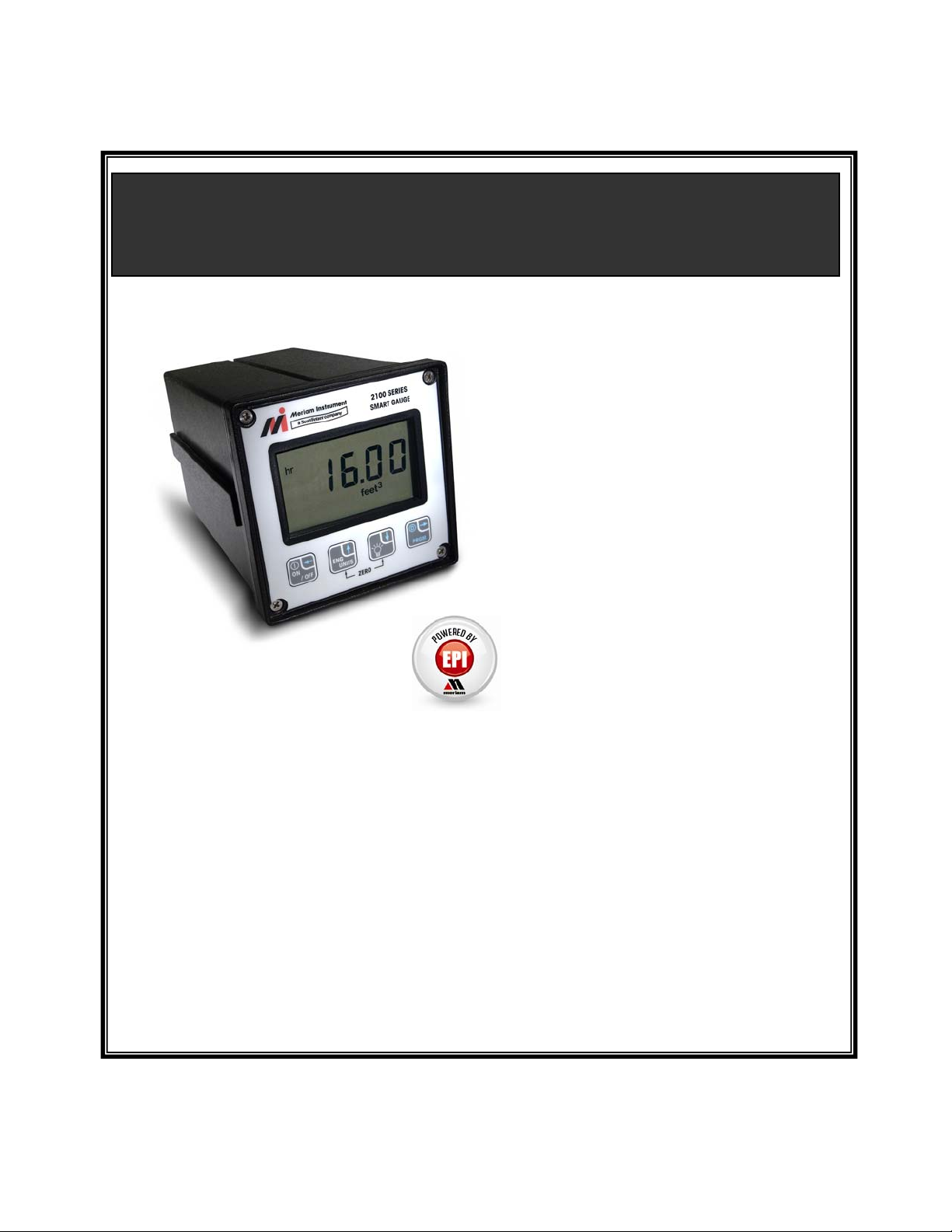
M2110F SMART FLOW GAUGE
OPERATING INSTRUCTIONS
Meriam’s M2110F Smart Flow Gauge is a
microprocessor-based pressure sensing
device with algorithms to calculate flow.
The gauge provides laminar flow element,
Accutube and Orifice Plate flow
measurements. Three configurations are
available: Battery, SetPoint, and Current
Loop models.
All models are programmable through the
front keypad. The user’s program
information is stored in non-volatile
memory, and is retained when the power
to the gauge is removed. SetPoint and
Current Loop models can also be
programmed through the RS-232 serial
communication connection.
1
Page 2

Table of Contents
1 OVERVIEW.......................................................................................................................................................4
1.1 FEATURES ...................................................................................................................................................4
1.2 MODELS ......................................................................................................................................................4
1.3 FLOW CALCULATION MODEL......................................................................................................................4
1.3.1 Laminar Flow element...........................................................................................................................4
1.3.2 Accutube or Orifice Plate element.........................................................................................................4
2 SAFETY WARNINGS.......................................................................................................................................5
3 CERTIFICATION / SAFETY / WARNINGS.................................................................................................6
4 FRONT PANEL.................................................................................................................................................7
4.1 FLOW METER DISPLAY .........................................................................................................................7
4.1.1 Indicators...............................................................................................................................................7
4.1.2 Display Refresh Rate ............................................................................................................................. 8
4.1.3 Display Resolution.................................................................................................................................8
4.2 KEYPAD OPERATIONS ..........................................................................................................................8
4.2.1 ON/OFF or BACKSPACE.....................................................................................................................8
4.2.2 ENGINEERING UNITS or UP ARROW...............................................................................................9
4.2.3 BACKLIGHT or DOWN ARROW..........................................................................................................9
4.2.4 PRGM or ENTER ................................................................................................................................10
4.2.5 ZERO FUNCTION...............................................................................................................................10
5 PROGRAMMING...........................................................................................................................................11
5.1 PROGRAMMABLE REGISTER LIST ...................................................................................................12
6 STARTUP REQUIREMENTS.......................................................................................................................13
6.1 POWER-UP SEQUENCE...............................................................................................................................13
6.2 POWER-UP ERROR CONDITIONS................................................................................................................13
6.2.1 Register Range Errors.........................................................................................................................13
6.2.2 Non-Register Data errors....................................................................................................................13
6.3 MEASUREMENT MODEL ............................................................................................................................13
6.4 LOW FLOW CUTOFF..................................................................................................................................14
6.5 B COEFFICIENT/FLOW CONSTANT.............................................................................................................14
6.6 C COEFFICIENT.......................................................................................................................................... 14
6.7 ZERO FLOW REFERENCE ...........................................................................................................................14
7 ZERO REFERENCE.......................................................................................................................................14
7.1 AFFECT ON OUTPUTS..........................................................................................................................14
7.1.1 RE-ZEROING THE GAUGE / OUTPUTS DISABLED (P5= 0): .........................................................14
7.1.2 RE-ZEROING THE GAUGE / OUTPUTS ENABLED (P5=1, 2 or 3):...............................................15
7.2 FACTORY ZERO....................................................................................................................................15
7.3 RANGE CHECK......................................................................................................................................15
8 ENGINEERING UNITS..................................................................................................................................16
8.1 CHANGING ENGINEERING UNITS.....................................................................................................16
9 PROGRAMMABLE REGISTERS................................................................................................................17
9.1 P0 – LOCKOUT CODE............................................................................................................................17
9.2 P1 – SHUTOFF TIMER...........................................................................................................................17
2
Page 3

9.3 P2- DISPLAY DAMP RATE...................................................................................................................18
9.4 P3 – MEASUREMENT MODEL.............................................................................................................18
9.5 P4 – LOW FLOW CUTOFF..................................................................................................................... 19
9.6 P5 – SETPOINT OPTIONS......................................................................................................................20
9.7 P6 AND P7 – SETPOINT (SET1 AND SET2).............................................................................................20
9.7.1 Setpoint Model.....................................................................................................................................20
9.7.2 Current Loop Model............................................................................................................................20
9.7.3 Data Entry ...........................................................................................................................................21
9.7.4 Scaling Dependency.............................................................................................................................21
9.8 P8 – DEADBAND....................................................................................................................................22
9.9 P9 – FLOW MEASUREMENT B-COEFFICIENT..................................................................................23
9.10 P10 – FLOW MEASUREMENT C-COEFFICIENT................................................................................24
10 REGISTER SECURITY .................................................................................................................................25
10.1 DESCRIPTION........................................................................................................................................25
10.2 VIEW-ONLY STATUS ...........................................................................................................................25
11 SERIAL PORT SERVICE..............................................................................................................................26
11.1 THE MENU..............................................................................................................................................26
11.2 ACCESSING THE MENU.......................................................................................................................26
11.3 IMPACT ON OPERATION.....................................................................................................................26
11.4 TIMEOUT................................................................................................................................................27
11.5 DATA MONITORING ............................................................................................................................27
11.6 LOCKOUT...............................................................................................................................................27
12 ERROR CODES ..............................................................................................................................................28
13 SUPPLEMENTARY INFORMATION.........................................................................................................29
13.1 APPLICATION EXAMPLE ............................................................................................................................29
13.1.1 Laminar flow element......................................................................................................................29
13.1.2 Accutube/Orifice Plate flow element...............................................................................................29
13.2 MAINTENANCE..........................................................................................................................................29
13.2.1 Battery Model Smart Gauge............................................................................................................29
14 INSTALLATION.............................................................................................................................................30
14.1 ELECTRICAL CONNECTIONS.............................................................................................................31
14.1.1 Power Supply Options.....................................................................................................................31
14.1.2 Setpoint Model Interface Connections............................................................................................31
14.2 CURRENT LOOP MODEL WIRING......................................................................................................32
14.2.1 Current Loop Model Interface Connections ...................................................................................32
14.3 OUTLINE DIMENSIONS .......................................................................................................................33
14.3.1 Panel Mounting...............................................................................................................................33
15 PRODUCT SPECIFICATIONS.....................................................................................................................34
16 SERVICE AND CALIBRATION...................................................................................................................36
3
Page 4

1 OVERVIEW
The Meriam Instrument M2110F Gauge is a microprocessor based flow-sensing device that can be used in
conjunction with a primary flow element to measure flow rate of clean dry gases. Compatible primary elements
include Laminar Flow Elements (LFE), Accutube and Orifice plates. The gauge operates on the principle of
measuring differential pressure across the primary element then calculating the flow rate based on user scaling input.
The calculated flow rate is then displayed in the selected engineering unit or output for process control or
monitoring.
1.1 Features
• Microprocessor –control for reliability and flexibility
• Remote control via RS232 serial link using ASCII character transfer
• Parameters to allow easy configuration of the unit
• Built-in non-volatile memory for storing register settings
• 4-½ digit LCD display with backlight for flow readout
1.2 Models
• Battery Powered Display Indicator only
• Current Loop Model with 4-20 mA Flow Rate Output and RS232 serial interface port
• 10 inH
• AC powered models have an RS232 serial interface port and SPDT outputs
1.3 Flow Calculation Model
O sensors available
2
1.3.1 Laminar Flow element
Flow = B_Coefficient * dP + C_Coefficient * dP
Where: dP = Differential pressure (inH
B-Coefficient and C-Coefficient are provided with the LFE
1.3.2 Accutube or Orifice Plate element
Flow = Flow Constant * √dP
Where: dP = Differential pressure (inH
O @ 4 ºC)
2
O @ 60 ºF)
2
2
Warning
The user must scale the gauge for the correct flow measurement display by entering the proper values of the
Measurement Model, B-Coefficient, C-Coefficient and or Flow Constant.
4
Page 5
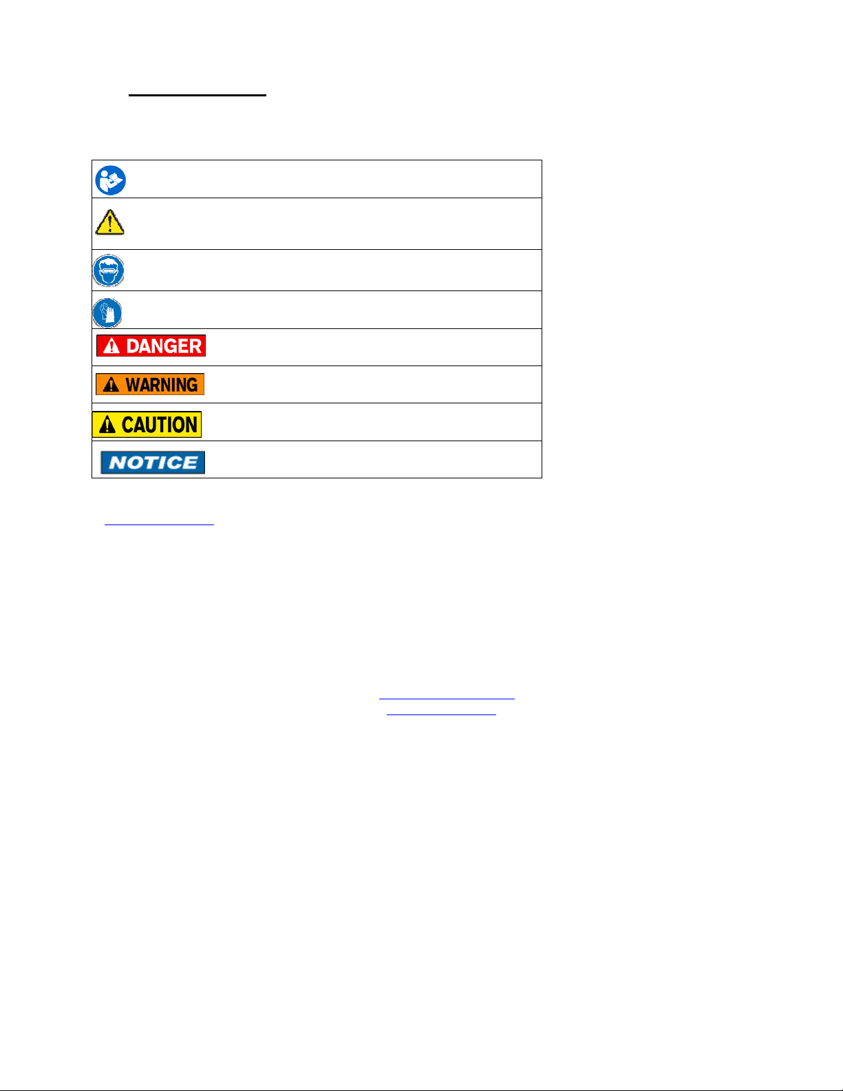
2 Safety Warnings
The table below defines the safety symbols, signal words and corresponding safety messa ges used in the
manual to identify potential hazards and are intended to warn persons about hazards that could result in
personal injury or equipment damage.
This is the Read Instruction Manual symbol. This symbol indicates
h that you must read the instruction manual.
This is the Safety Alert symbol. This symbol indicates a WARNING.
Warnings alert you to actions that can cause personal injury or pose a
physical threat. Please read these carefully.
This is the Safety Glasses symbol. This symbol indicates that you must
wear approved safety glasses during the task.
This is the Safety Gloves symbol. This symbol indicates that you must
wear approved safety gloves during the task.
Indicates a potentially hazardous situation which, if not
avoided, will result in death or serious injury.
Indicates a potentially hazardous situation which, if not
avoided, could result in death or serious injury.
Indicates a potentially hazardous situation which, if not
avoided, could result in minor or moderate injury.
Indicates information essential for proper product
installation, operation or maintenance.
Information in this document is subject to change without notice. Check the Meriam web site
(www.meriam.com
For customer assistance please call your local Meriam representative or Meriam directly.
) for the latest manual revision.
Meriam Process Technologies
10920 Madison Avenue
Cleveland, Ohio 44102
Telephone: (216) 281-1100
Fax: (216) 281-0228
E-mail: meriam@meriam.com
Web: www.meriam.com
5
Page 6

3 Certification / Safety / Warnings
Fire/Explosion Hazard. This instrument is not intrinsically safe. DO NOT use or
service in areas that may contain flammable gas or vapors, combustible dusts or
ignitable fibers where an unintended spark can cause a fire/explosion.
Do not exceed the Pressure Limits listed in the Specifications section of this
manual. Failure to operate within the specified pressure limit could result in
death or serious injury.
Do not exceed the Maximum Input Voltage listed under “Input Power” in the Specification section
of this manual
Do not exceed the Switch Rating listed under “I/O” in the Specifications section of this manual.
Disconnect power before servicing.
Substitution of components may impair operation and safety.
6
Page 7
4 FRONT PANEL
Warning
All settings must only be entered by qualified personnel, paying particular attention to the safety and precautionary
warnings. Changes to the register settings may cause incorrect flow rate display values.
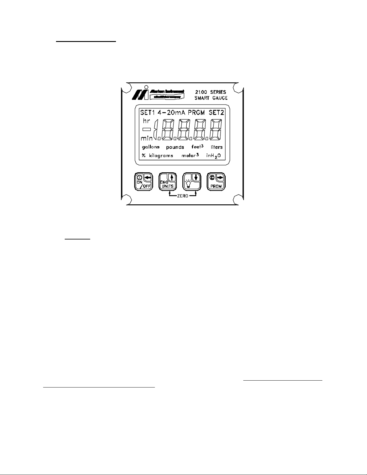
4.1 FLOW METER DISPLAY
4.1.1 Indicators
When the gauge is in the normal measurement mode of operation it will display the Flow Rate, Engineering Unit
and Time Base on the LCD display. The top of the display will show the following possible status indicators:
PRGM, SET1/SET2 or 4-20mA, which will be described below.
PRGM:
When the gauge is in Program Mode the display will illuminate the PRGM indicator, which prom pt s the user for
further keypad entry data.
SET1/SET2:
The SetPoint models will illuminate the SET1 or SET2 indicators to show active level sensing relay outputs. This
indicator is also used to indicate that the register that is being edited is used to configure the relay level sensing
function. These configuration registers include P5, P6 and P7 for the M2110F Relay Output Model.
4-20mA:
The Current Loop models will display the 4-20mA indicator when the 4-20 mA analog output is enabled or when
the user is editing the 4-20mA configuration register. These configuration registers include P5, P6, and P7 for the
M2110F Analog 4-20mA Output Model.
Decimal Point:
The decimal point is used to indicate the status of the Low Flow CutOff detection. If the Low Flow CutOff is active
the display will show a flashing decimal point.
7
Page 8

4.1.2 Display Refresh Rate
/ O
The M2110F Flow gauge converts signal data from the differential pressure sensor at a rate of ten conversions per
second depending on the operating mode of the gauge
. The display is then refreshed at a rate of approximately three
updates per second with a value that can be filtered by a user selectable time constant.
Note: All internal calculations, analog and contact outputs, and serial interface values are updated at the maximum
sampling rate.
4.1.3 Display Resolution
The differential pressure sensor range and the A/D conversion hardware in the device define the display resolution.
Note that since the Flow Gauge display is user-scaled to flow units, the full scale and resolution depends on the
calibration scaling. If a specific value will not fit on the 4½-digit display the auto-range feature will decrease the
resolution to allow the display value to fit the available digits.
4.2 KEYPAD OPERATIONS
The front panel keypad incorporates multifunction keys where the functionality will depend on the mode of
operation of the gauge.
• Measure Mode is the normal operating display mode of the gauge. This mode is always default after
power-up or reset.
• Program Mode is used to configure the gauge for operation. A PRGM indicator on the display denotes
this mode.
4.2.1 ON/OFF or BACKSPACE
Mode of
Operation
ON
Document Symbol: (Backspace←)
FF
Measure Mode
• Battery models: Toggles the gauge ON and OFF.
• SetPoint and Current Loop models: “Resets” the gauge.
Program Mode Backspace function:
Program Mode (P# displayed): backspace key will exit to Measure Mode.
Data Edit Mode: Backspace key is used to abort edit operation and exit the register
without making any changes.
Note:
When editing a multi-digit value, each backspace key press will backup one digit, until
finally exiting the register.
8
Page 9
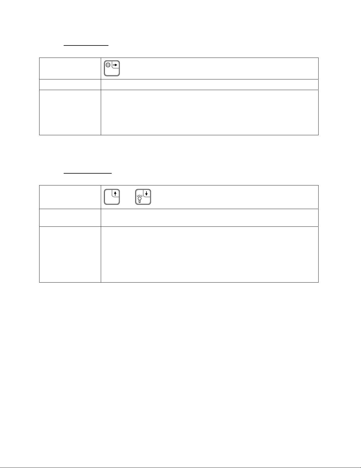
4.2.2 ENGINEERING UNITS or UP ARROW
Mode of
Operation
ENG
UNITS
Document Symbol: (Up↑)
Measure Mode No function in this mode. Will generate error code if pressed.
Program Mode
Program Mode (P# displayed): Scrolls up through the available programmable
registers.
Data Edit Mode: This key allows editing the register value by increasing the value of
the flashing digit.
As part of the P9 editing process the Engineering Unit selection can be changed. While
changing the units the current unit indicator remains solid, and the newly selected unit
indicator will flash. Scrolling through the available units is done by pressing the Up↑ or
Down↓ keys. The flashing unit is selected using the PRGM/ENTER→ key, or the
process may be aborted by using the Backspace← key.
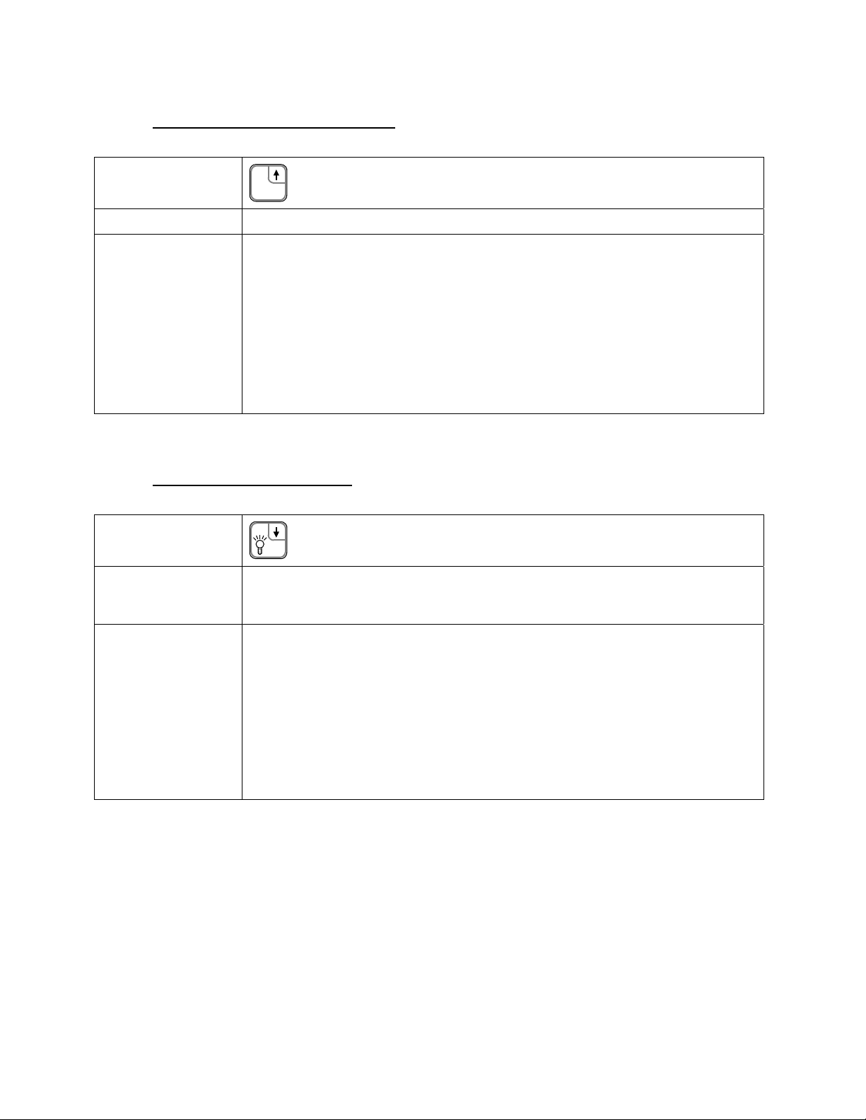
4.2.3 BACKLIGHT or DOWN ARROW
Mode of
Operation
Document Symbol: (Down↓)
Measure Mode Toggles the display Backlight on and off. Note that the default Backlight status for the
Battery model is OFF to conserve battery life. The other models will retain the prior
Backlight status as default.
Program Mode
Program Mode (P# displayed): Scrolls down through the available programmable
registers.
Data Edit Mode: This key allows editing the register value by decreasing the value of
the flashing digit.
As part of the P9 editing process the Engineering Unit selection can be changed. While
changing the units the current unit indicator remains solid, and the newly selected unit
indicator will flash. Scrolling through the available units is done by pressing the Up↑ or
Down↓ keys. The flashing unit is selected using the PRGM/ENTER→ key, or the
process may be aborted by using the Backspace← key.
9
Page 10
4.2.4 PRGM or ENTER
Mode of
Operation
Measure Mode Selects Program Mode, which allows access to the programmable registers P0-P10.
Program Mode Program Mode (P# displayed): Opens the selected register for editing.
PRGM
Data Edit Mode: When the desired value is selected, pressing the PRGM/ENTER→
key accepts and stores the value.
When editing a multi-digit value, each key press will accept the current digit and proceed
to the next until finally accepting the complete value and closing the register.
Document Symbol: (PRGM/Enter→)
4.2.5 ZERO FUNCTION
Mode of
Operation
Measure Mode
ENG
UNITS
+
In Measure Mode, pressing the Up↑ and Down↓ keys at the same time resets the zero
reference of the gauge (see page 16).
Document Symbol: (Up↑ and Down↓)
Program Mode In Program Mode, for convenience, this function will reset to P0.
Program Mode (P# displayed): Function will reset the register index to P0.
Data Edit Mode: After opening a register for editing, this function will reset the
register’s data value to default.
Note that even when using this “reset” function, the PRGM/Enter→ key must be
pressed to accept the new value. This allows for further editing after reset of the value.
10
Page 11
5 PROGRAMMING
IMPORTANT:
Programmable registers above P0 cannot be adjusted unless the correct lockou t code is entered or the lockout code is
disabled.
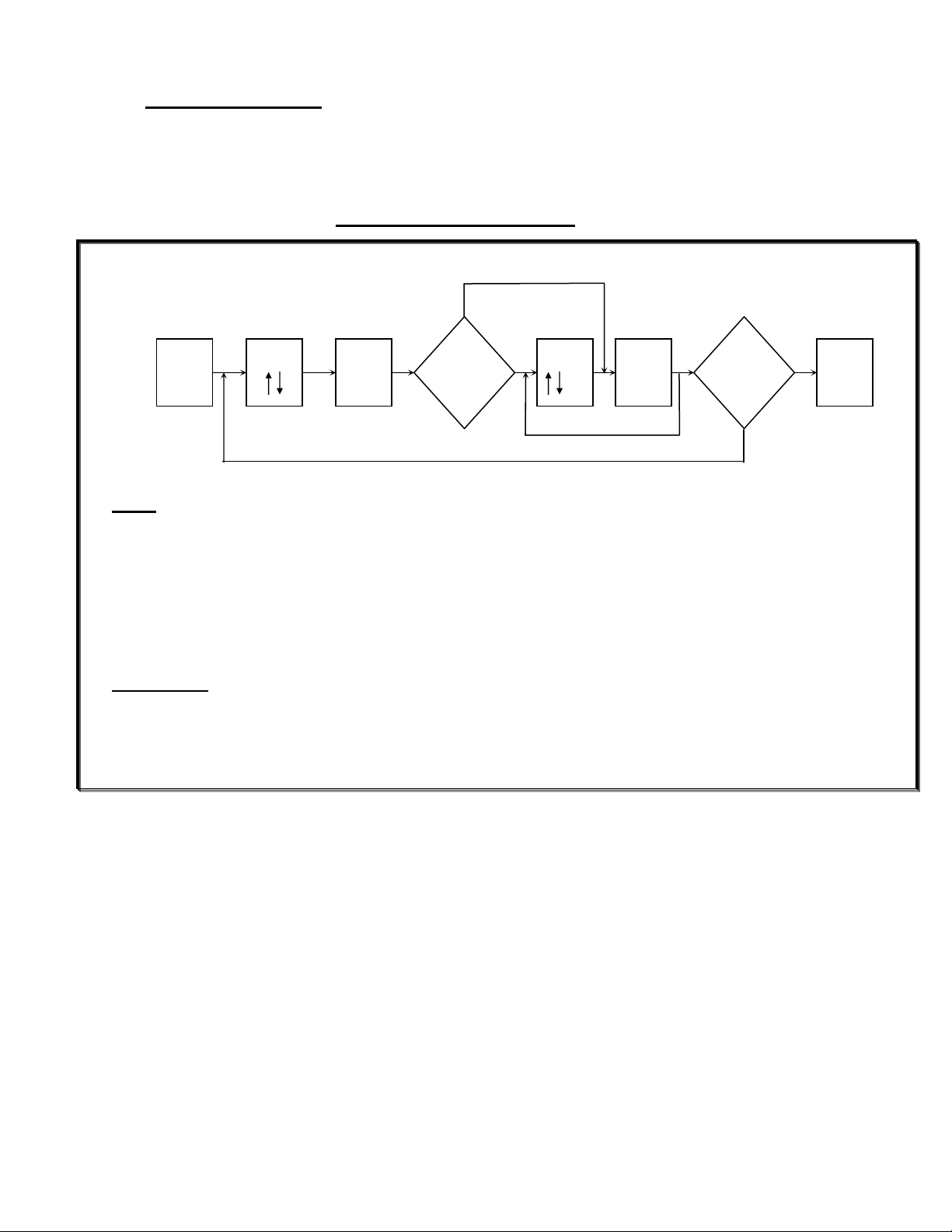
PROGRAM MODE ACCESS
no
[1] [2] [3] [5] [6] [8]
yes no no
yes
yes
Notes
[1] Enter program register selection mode
[2] Select register number to change
[3] View the value of the register currently selected
[4] Do you want to change the value? If not go to [6]
[5] Increase or decrease the value of the blinking digit, enter PRGM after each digit adjustment is made
[6] After modifying the final digit, PRGM will “store” the new value into memory
[7] Do other programmable registers need to be changed? If so, return to [2]
[8] Exit the program select mode and return to measurement display mode
Key Functions
Backspace : This key can be used to abort data entry and escape back to the measure mode display
Program : Enters data for storage or mode change
Up Arrow : Increments menu selections or digits being edited
Down Arrow : Decrements menu selections or digits bein g edi t e d
Press
Prgm
Press
Press
Prgm
[4]
Change
?
Press
Press
Prgm
[7]
Change
?
Press
ON/
OFF
11
Page 12

5.1 PROGRAMMABLE REGISTER LIST
All M2110F Flow Gauges have programmable registers that allow the gauge to be configured to fit the flow
measurement application. The programmable registers are numbered P0 through P10 and each register controls a
specific aspect of the gauge’s performance.
During any register editing operation the display will return to the measure mode display after one minute of keypad
activity. This will ensure that the gauge will be available for flow measurement observation even if it was
unintentionally left in the program display mode.
P#
P0 Lockout Code Lockout for security. 00 to 99 00 = Disabled.
P1 Time-out Automatic shutoff in minutes of
P2 Damp Rate Exponential damping time in seconds. 0.1, 0.2, 0.5, 1, 2, 5,
P3 Measurement
P4 Low Flow
P5 SetPoint
P6 SET1 Controls SET1 relay or 4.00 mA
P7 SET2 Controls SET2 relay or 20.0 mA
P8 Deadband Sets the amount of deadband in
P9 B-Coefficient /
P10 C-Coefficient
Name Description Value Range Notes
Pg. 14
Mode
CutOff
Options
Flow Constant
Scaling
Engineering
Units
Scaling
keypad inactivity.
Identifies the primary element
characteristic (Square Root or Linear)
Minimum display value that will be
viewed on the LCD and Serial I/O.
SetPoint Model: defines which relay
outputs are active.
Current Loop Model: defines the
status of the 4 - 20 mA outputs.
value.
value.
percent of full scale for relays.
The scaling constant required to
calibrate the flow measurement
equation.
After the entry of numeric data, access
to the units selection is allowed.
The scaling constant required to
calibrate the flow measurement
equation.
0 (disabled), 1, 2, 5,
10, 15, 25
10, 15, 25, 50
0) inH2O display
1) Laminar Flow
Element
2) Square Root
Element
-19999 to Max. Full
Scale
0 = Disabled.
1 = SET1 only.
2 = SET2 only.
3 = Both enabled.
0 = 4-20 disabled
1 = 4-20 enabled
–20% to +120% FS User defined value.
–20% to +120% FS User defined value.
0 (disabled), 0.1, 0.2,
0.5, 1, 2, 5, 10%
Mantissa range
+/- 9,999
Exponent Range
E+9 to E-9
Total Range
0 to 2250
Mantissa range
+/- 9,999
Exponent Range
E+9 to E-9
Total Range
+/- 2.0
Battery models only.
Pg. 14
0.1 = No Damping.
Pg. 15
Std. InH2O @ 20ºC
Pg. 15
LFE InH2O @ 4ºC
SQRT InH2O @ 60ºF
Decimal flashes when
activated.
Pg. 16
Setpoint and Current
Loop models only.
Pg. 17
Pg. 17
Pg. 17
SetPoint model only.
Pg. 19
A valid P9 setting is
required for P3=1 or 2.
User can scroll
through possible
engineering units.
Pg. 20
P10 required for LFE
devices.
P3 = 2 only.
Pg. 21
12
Page 13

6 STARTUP REQUIREMENTS
The initial power up of the M2110F Flow Gauge will require register configuration to match the requirements of the
application. The user will be required to enter data to properly characterize the connected flow element. This
information can be obtained from the supplier of the primary element.
6.1 Power-Up Sequence
After applying power to the units the gauge will perform the following functions:
Sequence of power-up or reset
1. Display test is performed; all segments of the LCD display are turned on
2. Firmware revision is displayed
3. Full-scale flow is displayed in the selected Engineering Units
4. All prior register values are restored and activated
5. Measure Mode displays the flow in Engineering Units
6.2 Power-Up Error Conditions
6.2.1 Register Range Errors
After power-up of the unit, the gauge will do a self-check of register settings to determine proper settings. If register
data is determined to be out of range, the gauge will reset those values to in-range defaults. The user will then be
notified of improper configuration settings with an error code display, see Error Code section for details.
Note:
If at power-up the register P9: B-Coefficient / Flow Constant is at a value of zero, the gauge will display inH
units in measure mode. If the user attempts to toggle the display to engineering units using the UP ARROW the
gauge will display an error and prompt the user to enter the P9 register value.
6.2.2 Non-Register Data errors
If the error condition is a not a register range error, the gauge will display the error code and then lock-up in the
error state.
Clearing the error condition can only be accomplished through a power down reset of the unit. This will involve
removing the battery connection on battery models and unplugging Setpoint and Current Loop models. If the error
cannot be cleared and an error code indicating a fatal fault is present, the units may have a hardware problem that
can only be corrected by servicing the unit.
O
2
6.3 Measurement Model
1. Access P3: Measurement Model
2. Configure the device for the connected primary element
P3 = 0 (Standard inH2O display @ 20ºC)
• Direct differential pressure reading from primary element
P3 = 1 (Laminar Flow Element @ 4ºC)
• Elements requiring measurement equation: Flow = B_Coeff*dP + C_Coeff*dP
P3 = 2 (Square Root Flow Element @ 60ºF)
• Elements requiring measurement equation: Flow = Flow Constant*√dP
2
Where: B_Coeff and C_Coeff and Flow Constant are calibration constant supplied with the primary element device.
13
Page 14

6.4 Low Flow CutOff
1. Access P4: Low Flow CutOff
2. Sets a flow level for which the readout LCD and serial port devices will display a clamped measurement
value.
• For P4 >= 0.0 (Positive or Zero)
• If the measured flow value is below the Low Flow CutOff, the unit display will be forced to a zero
display value. The decimal point will flash to indicate an active
• For P4 < 0.0 (Negative)
• If the measured flow value is more negative than the Low Flow CutOff, the unit will display the
P4 value. The decimal point will flash to indicate an active
Low Flow CutOff.
Low Flow CutOff.
6.5 B Coefficient/Flow Constant
1. Access P9: B Coefficient/Flow Constant
2. Scales the primary element modeling equation / sets engineering units
• Input the proper setting of this register for both modeling types
3. Select the proper engineering units to match the scaling coefficients see Engineering Units below
6.6 C Coefficient
1. Access P10: C Coefficient
2. Input the proper setting of this register for P3=0 (Laminar Flow Element Modeling)
3. Return to measure mode and verify display for configured units
6.7 Zero Flow Reference
1. Zero the gauge with zero flow through the primary element
2. Press the UP AND DOWN ARROW KEYS simultaneously
3. If lockout is in-active
• Gauge returns to MEASURE MODE
4. If lockout is active
• Enter Lockout Code
• Display will flash 0000 during zero sampling
5. Setpoints might be active(See page 12 for details)
display will flash 0000 during zero sampling
prompt will be L 00
7 ZERO REFERENCE
The gauge zeroing process requires that a flow generating less than 5% of the differential pressure sensors full-scale
range be present. This differential pressure generated from the primary element as the zero reference will be
measured by the pressure sensor and used as a zero reference for all future flow calculations. Prior to zeroing the
gauge all flow should be cut off to the primary element used as the differential pressure source for the gauge sensors.
7.1 AFFECT ON OUTPUTS
The SetPoint and Current Loop outputs are calculated based on the displayed flow. Since re-zeroing the gauge may
change the calculated flow, these outputs may be affected by the zeroing procedure. For safety purposes the process
should be in a zero flow condition with static pressure when the zeroing is initiated. After the zeroing the threshold
settings for the relay or current loop outputs should be checked for proper operation.
7.1.1 RE-ZEROING THE GAUGE / OUTPUTS DISABLED (P5=0):
1. Gauge in MEASURE MODE with zero flow through pri m ary element
2. Press the UP AND DOWN ARROW KEYS simultaneously
3. If lockout is in-active
• Gauge returns to MEASURE MODE
4. If lockout is active
• Enter Lockout Code
• Display will flash 0000 during zero sampling
• Gauge returns to MEASURE MODE
display will flash 0000 during zero sampling
prompt will be L 00
14
Page 15

7.1.2 RE-ZEROING THE GAUGE / OUTPUTS ENABLED (P5=1, 2 or 3):
1. Gauge in MEASURE MODE with zero flow through pri m ary element
2. Press the UP AND DOWN ARROW KEYS simultaneously
3. If lockout is in-active
• Press PRGM/ENTER before count reaches 0000 to acknowledge warning
• The display will again count from 0005 to 0000
• Press the UP AND DOWN ARROW keys before count reaches 0000
• The display will flash 0000 several times while sampling the new zero
• Gauge returns to MEASURE MODE
4. If lockout is active
• Enter Lockout Code
• Display will flash 0005 and count down to 0000
• Press PRGM/ENTER before count reaches 0000 to acknowledge warning
• The display will again count from 0005 to 0000
• Press the UP AND DOWN ARROW keys before count reaches 0000
• The display will flash 0000 several times while sampling the new zero
• Gauge returns to MEASURE MODE
display will flash 0005 and count down to 0000
prompt will be L 00
Warning
Never re-zero the gauge when connected to an active controlle d proces s or when known flow is present. The rezeroing process will alter the instrument's measurement output and could cause a sudden change in analog or relay
contact outputs.
7.2 FACTORY ZERO
The “Factory Zero” can be restored through the serial interface on the SetPoint and Current Loop gauge models.
This is the factory zero value determined during sensor calibration and is typically 0.0.
7.3 RANGE CHECK
The Smart Gauge can be zeroed only when the measured differential pressure is within ±5% of sensors full-scale
rating. If the applied differential pressure is greater than 5% of the rated value then an error code will be disp layed
when zeroing is attempted.
15
Page 16

8 ENGINEERING UNITS
The Engineering units are modified as part of the P9: B-Coefficient/Flow Constant editing process . The purpo se of
this dependency is to require the user to enter the required unit scaling prior to selecting the engineering units. Note
that the P10: C-Coefficient value may also need to be entered to provide proper scaling to the units selected.
The following engineering units are available on the M2110F Flow Gauge:
1. Gallons /Minute or /Hour
2. Pounds /Minute or /Hour
3. Cubic Feet /Minute or /Hour
4. Liters /Minute or /Hour
5. Percent /Minute or /Hour
6. Kilograms /Minute or /Hour
7. Cubic Meters/Minute or /Hour
8. InH
9. User Units
Notes:
[1] When InH
to the display scaling. The InH
temperature compensation.
[2] The menu selection indicated by all units flashing and is considered the USER UNITS selection. In measure
mode, indication that the USER UNITS are selected is shown by the absence of all unit indictors.
8.1 CHANGING ENGINEERING UNITS
The user should only change the engineering units at the time of setup and calibration. The engineering unit display
value is a direct function of the measurement model P3, and the scaling coefficients that are entered into the P9 and
P10 register values.
GAUGE IN MEASURE MODE
1. Press PRGM/ENTER to access P0 prompt
• If lockout is in-active
• If lockout is active
2. When P9 is displayed press PRGM/ENTER to access P9 value
• Modify the P9 decimal value used for the mantissa of the scaler
• Press PRGM/ENTER when finished modifying value
• Modify the P9 decimal value used for the exponent of the scaler
• Press PRGM/ENTER when finished modifying value
• The current engineering units will now be flashing
• Press ON/OFF to return to MEASURE MO DE
O Units1 –Sensor differential pressure
2
2
–User Defined Units
O units are selected the P9: B-Coefficient/Flow Constant and P10: C-Coefficients are not applicable
2
O display data is a direct read of the pressure sensor with the applied P3 related
2
prompt will be P0
• Increment P# using UP or DOWN ARROW until P9 is displayed
prompt will be L 00 with first digit flashing
• Enter Lockout Code
• Increment P# using UP or DOWN ARROW until P9 is displayed
• Use the UP/DOWN ARROWS to select the new engineering units
• Press PRGM/ENTER after selecting the new units
16
Page 17

9 PROGRAMMABLE REGISTERS
9.1 P0 – LOCKOUT CODE
This feature provides security in the Smart Gauge. It is designed to prevent unauthorized personnel from tampering
with or inadvertently changing the configuration of the gauge. The lockout is con trolled by a 2-digit setting in the
P0 register. If the lockout code is active, the gauge will prompt for the lockout code before allowing any changes to
register value. If the correct code is not entered when prompted, an error message will be displayed. If the operator
action was to re-zero the gauge, the gauge will simply return to normal Measure Mode operation, without accepting
any change. If the operator action was entering Program Mode, the gauge will enter a “view-only” status (see page
25), denoted by the PRGM indicator flashing.
In Program Mode (and during lockout code prompting), the register value is shown as “L xx” to assist in
identifying the register. The “L ” indicates “Lockout”, and “xx” will consist of the current value.
All Models
P#
P0
Name Description Value Range Notes
Lockout Code Lockout for security. 00 to 99 00 = Disabled.
GAUGE IN MEASURE MODE
1. Press PRGM/ENTER to access P0 prompt
2. If lockout is in-active
• Press PRGM/ENTER to access P0 value
• Press the UP or DOWN ARROWS to change each digit
• Press PRGM/ENTER to enter each digit
• Press the BACKSPACE to return to MEASURE MODE
3. If lockout is active
• Enter Lockout Code then continue as in 2) above
9.2 P1 – SHUTOFF TIMER
This register sets the automatic shutoff time. The Battery model will automatically shutoff if there is no keypad
activity for this length of time. This feature can be disabled by selecting zero in the P1 register. This will allow the
gauge to remain on until the ON/OFF key is pressed. Please note that usable battery life will be reduced if the unit
remains powered even when not in use. During programming, the choices found in the register correspond to the
actual time-out values, in minutes.
prompt will be P0
prompt will be L 00
Battery Models Only
P#
Name Description Value Range Notes
P1
Time-out Automatic shutoff in minutes of
keypad inactivity.
GAUGE IN MEASURE MODE
1. Press PRGM/ENTER to access P0 prompt
2. If lockout is in-active
• Increment P# using UP ARROW until P1 is displayed
• Press PRGM/ENTER to access P1 value
• Press the UP or DOWN ARROWS to change the selection
• Press PRGM/ENTER to enter the time-out selection
• Press the BACKSPACE to return to MEASURE MODE
3. If lockout is active
• Enter Lockout Code then continue as in 2) above
prompt will be P0
prompt will be L 00
17
0 (disabled), 1, 2, 5,
10, 15, 25
Battery model only.
Page 18

9.3 P2- DISPLAY DAMP RATE
The Smart Gauge has a selectable damping rate, which is used to filter the display. The damp rate setting is
approximately the time it will take for the gauge to ramp from one stable value to another. The filter characteristic
is exponential; changing at a slower rate as the final value is approached.
The “time constant” of the exponential equation is roughly one-fifth of the damp rate setting. This means that the
damped value will be roughly 63% of final value after a time equal to one-fifth of the register setting.
The damping function only affects the LCD display and RS 23 2 data val ue s. It does not
outputs or the 4 to 20 mA outputs.
P#
Name Description Value Range Notes
affect the action of the relay
P2
Damp Rate Exponential damping time in seconds. 0.1, 0.2, 0.5, 1, 2, 5,
10, 15, 25, 50
0.1 = No Damping.
GAUGE IN MEASURE MODE
1. Press PRGM/ENTER to access P0 prompt
2. If lockout is in-active
• Increment P# using UP ARROW until P2 is displayed
• Press PRGM/ENTER to access P2 value
• Press the UP or DOWN ARROWS to change the selection
• Press PRGM/ENTER to enter the damp rate selection
• Press the BACKSPACE to return to MEASURE MODE
3. If lockout is active
• Enter Lockout Code then continue as in 2) above
9.4 P3 – MEASUREMENT MODEL
The M2110F Flow Gauge will correctly measure flow when used with a primary element: LFE, Accutube or Orifice
plate by measuring the differential pressure across the primary element. Register P3 is used to describe the primary
element measurement characteristics as either square root or linear function. If P3=0 then the gauge will display the
differential pressure developed across the primary element.
P#
Name Description Value Range Notes
prompt will be P0
prompt will be L 00
All Models
P3 Measurement
Mode
GAUGE IN MEASURE MODE
1. Press PRGM/ENTER to access P0 prompt
2. If lockout is in-active
• Increment P# using UP ARROW until P3 is displayed
• Press PRGM/ENTER to access P3 value
• Press the UP or DOWN ARROWS to change the selection
• Press PRGM/ENTER to enter the measurement model selection
• Press the BACKSPACE to return to MEASURE MODE
3. If lockout is active
• Enter Lockout Code then continue as in 2) above
Identifies the primary element
characteristic ( Square Root or Linear)
The measured differential pressure is
automatically compensated for the
temperature reference defined for each
selection.
prompt will be P0
prompt will be L 00
18
0) inH2O display
1) Laminar Flow
Element
2) Square Root
Element
Std. inH2O @ 20ºC
P9 and P10 not used.
LFE inH2O @ 4ºC
SQRT inH2O @ 60ºF
P10 not used
Page 19

9.5 P4 – LOW FLOW CUTOFF
This register is used by the gauge to set a minimum active displayable flow value. Once the flow measurement falls
below this value the LCD on the front panel and the serial port will show zero flow. This will allow the user to set a
low flow threshold so that erroneous or noisy data at the low end of the measurement element will not be displayed
by the gauge. A typical setting value for this register might be 0.0 to prevent system noise from causing negative
flow measurements from being displayed.
The decimal point is used to indicate the status of the Low Flow CutOff detection. When the unit is in the measure
mode of operation and the flow rate falls below the Low Flow CutOff value. The display will show zero with a
flashing decimal point.
All Models
P#
P4
Name Description Value Range Notes
Low Flow
Display
CutOff
Flow threshold at which the display
will be held at zero.
-19999 to Max. Full
Scale
Display shows zero
with flashing decimal
when measurement
falls below this
threshold.
GAUGE IN MEASURE MODE
1. Press PRGM/ENTER to access P0 prompt
2. If lockout is in-active
• Increment P# using UP ARROW until P4 is displayed
• Press PRGM/ENTER to access P4 value
• Press the UP or DOWN ARROWS to change each digit
• Press PRGM/ENTER to enter each digit
• When the flashing decimal point is displayed, press the UP or DOWN ARROWS to change the decimal
point position and sign
• Press the BACKSPACE to return to MEASURE MODE
3. If lockout is active
• Enter Lockout Code then continue as in 2) above
prompt will be P0
prompt will be L 00
19
Page 20

9.6 P5 – SETPOINT OPTIONS
This register defines the output action for SetPoint and Current Loop models. Note that if an output is disabled by
this register the SetPoint value in its corresponding register (P6, P7) has no impact.
In Measure Mode, the indicators “SET1” and/or “SET2” will illuminate when the corresponding relay is energized.
The “4-20mA” indicator will illuminate when the Current Loop output is enabled. In Program Mode, the
indicators “SET1”, “SET2”, and “4-20mA” will illuminate as appropriate to assist when scrolling through the
register’s choices. Note that if P5 is set for active, the outputs will continue to update even in Program Mode,
according to the currently programmed values.
P#
Name Description Value Range Notes
SetPoint & Current Loop Models Only
P5
GAUGE IN MEASURE MODE
1. Press PRGM/ENTER to access P0 prompt
2. If lockout is in-active
3. If lockout is active
SetPoint
Options
• Increment P# using UP ARROW until P5 is displayed
• Press PRGM/ENTER to access P5 value
• Press the UP or DOWN ARROWS to change the selection
• Press PRGM/ENTER to enter the setpoint option selection
• Press the BACKSPACE to return to MEASURE MODE
• Enter Lockout Code then continue as in 2) above
SetPoint Model: defines which relay
outputs are active.
Current Loop Model: defines the
status of the 4 - 20 mA output.
prompt will be P0
prompt will be L 00
9.7 P6 and P7 – SETPOINT (SET1 and SET2)
9.7.1 Setpoint Model
0 = Disabled.
1 = SET1 only.
2 = SET2 only.
3 = Both enabled.
0 = 4-20 disabled
1 = 4-20 enabled
SetPoint & Current Loop Models Only
Not found on Battery
model.
These programmable registers define the flow values at which the relay outputs will energize. The relay will
energize when the flow exceeds its corresponding value, and de-e ner gize when the flow drops below the value
minus the deadband. Register P6 defines the SET1 relay detection threshold and P7 defines the SET2 relay
detection threshold.
9.7.2 Current Loop Model
These programmable registers define the 4 to 20 mA output scaling and range. The P6, SET1 value defines the flow
rate that will be represented by a 4.00 mA output signal. The P7, SET2 value defines the flow rate that will be
represented by a 20.00 mA output signal. Other flow values provide an output that is linearly scaled between the
two end points P6 and P7. For values beyond the defined range the output is li mited from 4.00 to 20.38 mA. The
P6 (4-mA) register can be set greater than the P7 (20-mA) register, to create a reverse acting output. The limits are
–20% to +120% full scale, but P6 and P7 cannot be set at equal values.
20
Page 21

9.7.3 Data Entry
These programmable registers are entered in the current Engineering Unit used by the gauge, which are illuminated
during edit of these programmable registers. For example, if the gauge is set to read in gallons/minute, and a value
of 110 is put into the P6 register the SET1 relay will energize at 110 gallons.
In Program Mode, the indicators “SET1”, “SET2”, and “4-20mA” will illuminate as appropriate to assist in
identifying the edited register. For example, when scrolling to and/or editing P6, “SET1” will illuminate indicating
that SET1 is being edited. The same indication applies to the access of the P7/“SET2” value. The “4-20mA” will
be illuminated if the gauge is a Current Loop model to indicate that the 4-20mA range is being edited.
9.7.4 Scaling Dependency
If the Engineering Unit is changed along with the appropriate scaling factors the value in the P6 and P7
programmable registers may also require correction to reflect the changes to the scaling and un its.
P#
P6
P7
GAUGE IN MEASURE MODE
1. Press PRGM/ENTER to access P0 prompt
2. If lockout is in-active
3. If lockout is active
Name Description Value Range Notes
SET1 Controls SET1 relay or 4.00 mA
SET2 Controls SET2 relay or 20.0 mA
• Increment P# using UP ARROW until P6 or P7 is displayed
• Press PRGM/ENTER to access the register value
• Press the UP or DOWN ARROWS to change each digit
• Press PRGM/ENTER to enter each digit
• When the flashing decimal point is displayed, Press the UP or DOWN ARROWS to change the decimal
point position and sign
• Press PRGM/ENTER to enter the decimal and sign
• Press the BACKSPACE to return to MEASURE MODE
• Enter Lockout Code then continue as in 2) above
value.
value.
prompt will be P0
prompt will be L 00
–20% to +120% FS User defined value.
P6 cannot equal P7
–20% to +120% FS User defined value.
P6 cannot equal P7
21
Page 22

9.8 P8 – DEADBAND
This register is found on the SetPoint model only. The deadband can be set to 0 (disabled), 0.1, 0.2, 0.5, 1, 2, 5 and
10% of full scale flow. The relay will energize at the value in its corresponding P6 and P7 programmable registers
for increasing flow values. The relay will de-energize at a value equal to the corresponding P6 and P7 register,
minus the deadband value for decreasing flow values. With a 0% deadband setting, the relays will energize and
reset precisely at the values in the corresponding P6 and P7 programmable registers. The programming choices
found in the register menu correspond to the actual deadband values in percent full scale.
SetPoint Models Only
P#
P8
GAUGE IN MEASURE MODE
1. Press PRGM/ENTER to access P0 prompt
2. If lockout is in-active
3. If lockout is active
Name Description Value Range Notes
Deadband Sets the amount of deadband in
percent of full scale for relays.
prompt will be P0
• Increment P# using UP ARROW until P8 is displayed
• Press PRGM/ENTER to access P8 value
• Press the UP or DOWN ARROWS to change the selection
• Press PRGM/ENTER to enter the deadband setting selection
• Press the BACKSPACE to return to MEASURE MODE
prompt will be L 00
• Enter Lockout Code then continue as in 2) above
0 (disabled), 0.1, 0.2,
0.5, 1, 2, 5, 10%
SetPoint model only.
22
Page 23

9.9 P9 – FLOW MEASUREMENT B-COEFFICIENT
All Models
The Flow Gauge calculates flow based on the differential pressure that develops across the primary element used in
the flow path. By defining the characteristics of the differential pressure drop as a square root or linear function the
smart gauge can calculate the flow rate from the sampled differential pressure. The P9 register defines the scaling
for the square root primary element, while the P9 and P10 programmable registers together specify the linear
coefficients for the LFE primary elements.
The P9 register is entered in multiple parts, decimal digit (mantissa) and x10 factor (exponent). This is required
because of the wide range of the B-coefficient values depending upon the size, type and rating of the primary
element. This register is entered first as the decimal (mantissa) part using the normal entry method. Following the
entry of this value the display will prompt the user for a x10 factor (exponential) value in the range of E-9 to E+9.
Only after the user has edited the P9 value will access to the unit selection list be allowed.
Example : B-Coefficient = .000123 : From primary element data sheet
B-Coefficient = .000123 = 1.23 x 10
Data Entry Display for P9: 1.230 (After Program mode enter)
- E3 (After Decimal digit enter)
P#
Name Description Value Range Notes
-4
= 1.23 E -4
P9
GAUGE IN MEASURE MODE
1. Press PRGM/ENTER to access P0 prompt
2. If lockout is in-active
3. If lockout is active
B-Coefficient
Scaling
• Increment P# using UP ARROW until P9 is displayed
• Press PRGM/ENTER to access the register value
• Press the UP or DOWN ARROWS to change each digit
• Press PRGM/ENTER to enter each digit
• When the flashing decimal point is displayed, Press the UP or DOWN ARROWS to change the sign
• Press PRGM/ENTER to enter the value and sign
• Enter Lockout Code then continue as explained in 2) above
The scaling constant required
calibrating the flow measurement
equation.
Engineering Units Selection List
prompt will be P0
prompt will be L 00
Mantissa range
+/- 9.999
Exponent Range
E+9 to E-9
Total Range
0 to 2250
Gallons /Minute
/Hour
Pounds /Minute
/Hour
Cubic Feet /Minute
/Hour
Liters /Minute
/Hour
Percent /Minute
/Hour
Kilograms /Minute
/Hour
Cubic Meters /Minute
/Hour
InH
O Units
2
User Units
1) P9 is required for
2) If P5 = setpoints
Pg. 25
The actual Flow
display magnitude will
depend on the scaling
values entered in to P9
and P10.
LFE and Square
Root devices.
enabled ,and P9 is
set to zero
23
Page 24

4. The display shows the exponent value for P9. Press the UP or DOWN ARROWS to change the exponent
digit.
• Press PRGM/ENTER to enter the digit, the decimal point will flash
• Press the UP or DOWN ARROWS to change the sign of the exponent
• Press PRGM/ENTER to enter the exponent value
• The present engineering units will be flashing. Press the UP or DOWN ARROWS to scroll through the
possible units.
• Press PRGM/ENTER to enter the selected units
5. The current engineering unit will now be flashing
• Use the UP/DOWN ARROWS to select the new engineering unit
• The user can rotate through the list of possible units and time bases
• Press PRGM/ENTER after selecting the new units
6. Press the BACKSPACE to return to MEASURE MODE
9.10 P10 – FLOW MEASUREMENT C-COEFFICIENT
All Models
The Flow Gauge calculates flow based on the differential pressure that develops across the primary element in the
flow path. By defining the characteristics of the differential pressure drop as a square root or linear function, the
smart gauge can calculate the flow rate from the sampled differential pressure. The P9 register defines the scaling
for the square root primary element, while the P9 and P10 programmable registers together specify the linear
coefficients for the LFE primary elements.
The P10 register is entered in multiple parts, decimal digit (mantissa) and x10 factor (exponent). This is required
because of the wide range of the C-coefficient values depending upon the size, type and rating of the primary
elements. This register is entered first as the decimal (mantissa) part using the normal entry method. Following the
entry of this value the display will prompt the user for a x10 factor (exponential) value in the range of E-9 to E+9.
Example: C-Coefficient = .000123: From primary element data sheet
C-Coefficient = .000123 = 1.23 x 10
Data Entry Display for P10: 1.230 (After Program mode enter)
- E4 (After Decimal digit enter)
P#
Name Description Value Range Notes
-4
= 1.23 E -4
P10
C-Coefficient
Scaling
The scaling constant required
calibrating the flow measurement
equation.
24
Mantissa range
+/- 9.999
Exponent Range
E+9 to E-9
Total Range
+/- 2.0
P10 required for LFE
devices.
Page 25

GAUGE IN MEASURE MODE
1. Press PRGM/ENTER to access P0 prompt
2. If lockout is in-active
• Increment P# using UP ARROW until P10 is displayed
• Press PRGM/ENTER to access the register value
• Press the UP or DOWN ARROWS to change each digit
• Press PRGM/ENTER to enter each digit
• When the flashing decimal point is displayed, Press the UP or DOWN ARROWS to change the sign.
• Press PRGM/ENTER to enter the value and sign
3. The display shows the exponent value for P10. Press the UP or DOWN ARROWS to change the exponent
digit.
• Press PRGM/ENTER to enter the digit, the decimal point will flash
• Press the UP or DOWN ARROWS to change the sign of the exponent
• Press PRGM/ENTER to enter the exponent value
• Press the BACKSPACE to return to MEASURE MODE
4. If lockout is active
• Enter Lockout Code then continue as in 2) above
prompt will be P0
prompt will be L 00
10 REGISTER SECURITY
10.1 DESCRIPTION
When a gauge is “locked” for security purposes, it does not allow access to register data without first providing the
lockout code. A gauge is “locked” by entering a lockout code into the P0 register. After pressing a key on a locked
gauge for a desired function “L 00” will appear on the display, with the first 0 flashing. This is the prompt to enter
the lockout code.
10.2 VIEW-ONLY STATUS
If a user attempts to enter Program Mode without providing a correct lockout code, the gauge briefly provides an
error message, and then enters a “view-only” status, denoted by the PRGM indicator flashing. In this mode, all
programmable registers except the lockout code register itself can be viewed, but not changed.
In this view-only status, the operator navigates through the programmable registers exactly the same as if
programming the programmable registers. However, the keys that would change a value are simply ignored by the
gauge. Thus, the PRGM/Enter→ key will open a register normally; the Backspace← key will close the register,
and then return to Measure Mode as expected. The Up and Down Arrow keys do nothing within the register.
GAUGE IN MEASURE MODE
1. Press PRGM/ENTER to access P0 prompt
2. If lockout is active
• Enter Lockout Code
• Press the UP or DOWN ARROWS to change each digit
• Press PRGM/ENTER to enter each digit
If the correct code was entered, the gauge will perform the requested function. Otherwise, an error message is
displayed, and the gauge either returns to Measure Mode, or enters a “view-only” status for the programmable
registers (if Program Mode was requested).
prompt will be L 00
25
Page 26

11 SERIAL PORT SERVICE
SetPoint & Current Loop Models Only
The M2110F Smart Flow Gauge SetPoint and Current Loop models provide RS-232C communication capability.
To use the serial service, connect a standard “dumb terminal” or personal computer with terminal software as shown
in the wiring diagram on page 29. Set the terminal communication for 9600 baud, 8 data bits, no parity, one stop bit,
and no handshaking. The terminal should be able to display at least 24 lines and 70 columns.
11.1 THE MENU
All programmable items of the gauge are available from the menu. Included with the menu is a complete summary
of all data representing the current programming and operating status.
A sample view of the menu is shown below for reference. The top line identifies the gauge, firmware revision, and
copyright. The second line displays the gauge model, the full-scale sensor range, and the sensor identifier. Next is a
reminder notice to the operator (explained below).
Finally, all programmable registers and functions are formatted on the menu. The menu item includes its menuselection character, and the current register data as applicable. To change an item, simply select its character from
the terminal keypad; the appropriate sub-menu, notes, and instructions are presented for operator entry. Note that
the serial menu typically provides more flexibility for entering data values, compared with the gauge’s keypad.
SmartGauge/M2110F (vX.XX). (c) Copyright 2010 Meriam
SetPoint model. Sensor = 28.00 InH2O
-------------------------------------------------------------------Notice! Changing any value will PAUSE Gauge Operation; see manual!
-------------------------------------------------------------------Current Full Scale: 25.00 Cu.Ft./hour
-------------------------------------------------------------------A) P0, LockOut Code = Disabled
B) P2, Damp Rate = 0.2 Seconds
C) P3, Measurement Mode = Square Root
D) P4, Minimum Display = 1.0000 Cu.Ft./hr.
E) P5, SetPoint Ctrl = Disabled
F) P6, SET1 = 0.0000 Cu.Ft./hr.
G) P7, SET2 = 0.0000 Cu.Ft./hr.
H) P8, Dead Band = 0.0 % Full Scale
I) P9, B Coefficient = 1.2340E-01
& Units
J) P10,C Coefficient = Not Available P3=2(Square Root)
L) Restore Factory Zero M) ReZero Gauge
X) EXIT Interactive Menu
Select Choice:
11.2 ACCESSING THE MENU
When the gauge is powered up or reset, it will print the menu to the serial port. Also, hitting the ENTER key from
the terminal will reprint the menu. If the terminal is not connected when the gauge prints the menu after power up,
the user will see no screen text until he/she presses the ENTER key to establish communications with the device.
11.3 IMPACT ON OPERATION
Use of the serial port service is independent of the operating mode of the gauge, and vice versa. It is not necessary
to change to Program Mode to use any of the menu’s features, editing programmable registers or re-zeroing. The
gauge continues its active operation regardless of the serial port service, except for the pausing explained in the next
paragraph. Any keypad activity from the front panel of the gauge will also be processed regardless of the serial port
status. If entries are made through the keypad and the serial port simultaneously, the last entry received will be
active.
26
Page 27

While the serial port is transferring data, the other functions of the gauge are paused to allow this task to complete.
In this paused state, the display is frozen and the outputs are not updating. Typically, the data transfers are very
short and thus the interruption is minimal. However, selecting a register for edit will completely stop normal gauge
operation, because the gauge is awaiting the operator’s input. During this state, the display is blanked and as soon as
the operator selection or entry is complete, the gauge resumes normal operation.
Warning
The Notice of “PAUSE Gauge Operation” near the top of the menu is a reminder about this explanation. It is
particularly important when a gauge is in service as an in-process instrument, since the gauge will not respond to
process conditions while it is paused.
11.4 TIMEOUT
When the menu is displayed, it has no impact on gauge operation or performance. Therefore, the menu will remain
displayed indefinitely, or until the operator takes action or the gauge is reset. When the gauge is stopped awaiting
operator input the gauge’s display is blanked and the outputs are frozen. In this state, if there is no terminal
keyboard activity for approximately one-minute, the operation will time-out and the gauge is returned to its
operating mode.
11.5 DATA MONITORING
Selecting “X” from the menu will EXIT the menu and begin data monitoring. If the gauge was in Program Mode,
it will be returned to Measure Mode to allow data monitoring.
During data monitoring, every analog-to-digital conversion from the pressure sensor is displayed on the terminal.
The additional load of the continuous serial communication will slightly reduce the overall performance of the
gauge. The resulting data rate will typically be about ten (10) conversions per second, depending on various
operating conditions. Note that the data sent to the terminal will be damped according to the damp rate set in
register P2.
The data includes the pressure value and Engineering Units, as well as the output status of either the relay SET1 ON,
SET2 ON or the 4-20 mA output value, if set. Note that this status indication is the internal calculated value, as
there is no feedback hardware on the gauge. "Over Pressure!” is indicated if the input pressure exceeds 120% of the
full-scale sensor range. This indication acts on the direct measurement of pressure regardless of the damp rate
setting.
If the gauge is taken out of serial Measure Mode the data monitoring function will pause with a message. The
menu is available at this time, as it is at any time, by hitting ENTER from the terminal. When the gauge is returned
to Measure Mode, if the menu was not activated, data monitoring will automatically resume.
Data logging can be accomplished be invoking the appropriate logging function of the terminal software.
To EXIT the data monitoring function, simply hit ENTER on the terminal to restore the menu.
11.6 LOCKOUT
If the lockout feature is active, see register P0, the serial menu will prompt for the lockout code if necessary. For
security purposes, an asterisk (*) is displayed instead of the character as it is typed. When entering a new lockout
code through the serial port, however the code is displayed as it is typed, since there is no confirmation step.
27
Page 28

12 ERROR CODES
All Smart Gauge models have an error/message feature to inform the operator of problems with the operation or
programming of the gauge. These Error Codes and messages are identified and described in the table below.
ERROR DESCRIPTION
“OP” Overpressure warning. The measured pressure exceeds the full-scale pressure by 20% of full scale or
more. Sensor is at risk of permanent damage!
E001 Automatic Shutoff timer has expired (Battery model only); gauge is shutting down normally.
E002 Requested ZERO value is not within 5% of full-scale pressure, and therefore ignored.
E003 Requested SET1 or SET2 is out of range. Must be greater than 0 and less than +120% Full Scale.
E004 SET1and SET2 values are equal. This configuration is not acceptable on Current Loop models. To
disable the output, Set register P5 = 0 (see page 1).
E005 User register found to be out of range after powerup. The register was forced to a default value and
then re-saved to memory by the initialization function.
E006 User entered incorrect Lockout Code. Gauge is locked. A view-only status will be entered if Program
Mode was requested.
E007 Access to P10 register was rejected because P10 is invalid when P3 = 0 or P3=2.
E008 Entry of the P9 or P10 register value was out of range. Access to P9 was rejected because of P3 = 0
setting. The output functions P5 were disabled because user entered P9 = 0.
E009 Access to P5, P6, or P7 was rejected because the value of P9 = 0.0. The user must enter a usable value
into P9 before access to P5-P7 is allowed.
E010 Full Scale Range for Engineering Units selected is beyond scale of display (>19,999) or the full-scale
range is equal to zero because of incorrect P9 or P10 register setting.
E011 User attempted to use the ENG arrow key in measure mode. This key has no function in this mode,
see P3 setup and P9 entry for units selection process.
E012 User attempted to enter P4 Low Flow Cut Off value greater than or equal to the Full Scale Units.
E020 Low Battery (or power supply) Warning. This error will show repeatedly approximately every 10
seconds, so long as the voltage supply remains low.
E030* EEProm Error. Display alternates between “E030” and a sub-Ecode. This error is generated if the
EEProm data is out of range after power-up. Units can recover from these errors by OFF/ON reset.
The variables are forced into range after the OFF/ON reset. If the unit cannot recover from the
Error, the fault may be due to hardware malfunction. Please consult the factory for assistance.
All programmable registers should be rechecked for valid data after power-up.
E110 Displayed flow or pressure range error. The value to be displayed is out of range. Check the settings
E210* Internal display error. Cannot display character . Consult factory, possible hardware problem.
E211* Internal display error.
E213* Internal display error. Attempting to display 2.0000 on the display.
• These Error codes may indicate a hardware or other internal problems; if the problem cannot be corrected by
cycling the input power supply on and off, please take note of the error code and operating conditions, and
contact Meriam Instrument at (216) 281-1100.
SUB-
ECODE
1 Factory sensor detection error: Sensor range or type is invalid
2 Not Used
4 Not Used
8 Factory or User Zero value is out of range
16 User register found out of range
32 Factory configured data pressure incorrect
64 Factory configured temperature data incorrect
128 EEProm data storage error
of P3, P9 and P10. Note: P9 cannot equal zero when P3 = 1 (LFE) or 2 (Sq.Rt) modes.
DESCRIPTION
Note: Ecode is accumulation of errors. Example: ECode 129 = Error 1 and Error 128
28
Page 29

13 SUPPLEMENTARY INFORMATION
13.1 Application Example
13.1.1 Laminar flow element
Primary Element: Laminar Flow Element (LFE)
Model 50MJ10-9
Nominal Air flow Range = 3.00 cubic feet/minute
B-Coefficient = 4.2847E-1
C-Coefficient = -5.0523E-3
Gauge requirement: M2110F with 10.00 inH2O sensor
Application requirements: Monitor airflow in units of cubic feet/minute
Setup Relay outputs to detect low limit at 1.25 cu.ft/min
Settings: P3 = 1 : Measurement Model = LFE
P5 = 1 : Setpoint Option = SET1 Only
P6 = 1.250 : SET1 limit = 1.250 cu.ft/min
P9 = 4.285 : Rounded deci mal part of the B-Coefficient
= - E1 : Exponent of B-Coefficient
P10 = -5.052 : Rounded decimal part of the C-Coefficient
= - E3 : Exponent of C-Coefficient
13.1.2 Accutube/Orifice Plate flow element
Primary Element: Accutube Flow Element
Maximum Air flow Range = 750 SCFM
DP at maximum air flow = 15 inH
Application requirements: Monitor airflow in units of cubic feet/minute
Setup Relay outputs to detect low limit at 25 cu.ft/min
Gauge requirement: M2110F with 28.000 inH
Settings: P3 = 2 : Measurement Model = Square Root Device
P5 = 1 : Setpoint Option = SET1 Only
P6 = 25 : SET1 limit = 25 cu.ft/min
P9 = 193.65 : Flow Constant =
O
2
O sensor
2
FlowRangeMaximumAir
mAirFlowDPatMaximu
13.2 Maintenance
13.2.1 Battery Model Smart Gaug e
The battery can be changed by removing the front face cover on the smart gauge and then removing the PC board
assemblies as described below.
1. Remove the four (4) front face screws.
2. Carefully fold down front face cover and slide electronics board assembly forward until the sensor ribbon cable
can be unplugged.
3. Slide the assembly completely out of the housing, unplug battery board and attach replacement.
4. Re-assemble the unit in reverse order.
5. Check to ensure that the sensor cable, battery board and front panel
the front faceplate.
are re-connected properly before reattaching
29
Page 30

14 INSTALLATION
Differential pressure sensors have two pressure connections on the back of the gauge. The diagram below shows the
correct connections to obtain the desired type of pressure measurement.
The SetPoint model
utilizes the multifunction terminal strip
shown at the left. This
terminal strip has a
NEMA 1 rating. The
SPDT relays are not
powered internally by the
gauge. Jumpers from the
24Vdc, 110Vac or
220Vac power sources
can be used if required.
The Current Loop
model uses a cannon
connector that is
designed to meet NEMA
4X requirements. The
charts at the left show the
terminal and wiring
arrangement. See wiring
schematics for the three
and four wire, 4 to 20
mA loops shown.
Note: The Smart Gauge comes with 1/8” FNPT pressure port(s). Gauge and Absolute models
only use one pressure port. The unused port vents the enclosure/sensor to atmosphere. DO NOT
REMOVE THE SINTERED PLUG (ALLEN HEAD FITTING). The Smart Gauge should be
panel-mounted or held firmly in one hand while a small wrench is used to tighten the 1/8”
MNPT pipe thread. Do not tighten the fitting without using a wrench on the manifold.
30
Page 31

14.1 ELECTRICAL CONNECTIONS
Setpoint models come with a terminal block interface while the Current Loop model comes with an eight-pin
circular connector/cable interface. Note: The cable is supplied with the Current Loop model.
14.1.1 Power Supply Options
The M2110F SMART GAUGE can be supplied in three possible hardware configurations.
1. Battery Model ..………….Unit powered by internal batteries
2. Setpoint Model …………..Unit includes two programmable relay outputs
3. Current Loop Model …….Unit includes 4-20 mA output
14.1.2 Setpoint Model Interface Connections
Terminal
1
2 SET1 / C Relay1 output Common
3 SET1 / NC Relay1 output Normally closed
4 SET2 / NO Relay2 output Normally open
5 SET2 / C Relay2 output Common
6 SET2 / NC Relay2 output Normally closed
7 No Connection None
8 RS232 Common RS232 interface common connection 0 VDC
9 RS232 Tx RS232 transmit output connection For Serial Menu
10 RS232 Rx RS232 receive input connection For Serial Menu
A
B GND AC Ground
Description Function Notes
SET1 / NO Relay1 output Normally open
Frame Ground Earth Connection
NO EXTERNAL POWER SUPPLY REQUIRED
EXTERNAL POWER SOURCE: 24 VDC, 115 VAC or 230 VAC
EXTERNAL POWER SOURCE: 24 VDC
C 0 VDC Common Connect only if not using AC inputs
D +24 VDC IN +24 VDC Input Nominal Connect only if not using AC inputs
E Reconnectable Transformer Primary Jump er E to H NC
F Reconnectable Transformer Primary Jumper F to J NC
H L2 Reconnectable Transformer Primary (See E above) L2 / 230 VAC
J Reconnectable Transformer Primary (See F above) Jumper J to K
K N Transformer Primary Fused Input Line Neutral
L L1 / L Transformer Primary Fused Input L 115 VAC L1 / 230VAC
DC POWER SUPPLY CONNECTIONS
AC POWER SUPPLY CONNECTIONS
Reconnectable 115/230 Primary
115 VAC
INPUT
230 VAC
INPUT
Note: See Appendix for wiring specifics.
31
Page 32

14.2 CURRENT LOOP MODEL WIRING
14.2.1 Current Loop Model Interface Connections
The Current Loop Model connections are made through the supplied interface cable. The cable is connected to an
eight (8) pin circular receptacle on the back of the unit. These connections will be defined by wire color coding of
the cable.
Pin # Wire
Description Function Notes
Color
1
2 WHITE -LOOP 4-20 mA Analog Return (+) mA output to receiver
3 RED +LOOP 4-20 mA Loop Power Input
4 GREEN +24VDC IN Gauge Power Supply Input + 24 VDC Input Nominal
5 NOT USED
6 BROWN RS232 Common RS232 interface common connection 0 VDC
7 BLUE RS232 Rx RS232 receive input connection For Serial Menu
8 ORANGE RS232 Tx RS232 transmit output connection For Serial Menu
BLACK
0 VDC IN Gau ge Power Supply Common 0 VDC Input
Note: See Appendix for wiring specifics.
2110F
4
3
2
1
R
24 VDC/ 50 mA
Power Supply
+
-
Gauge & Loop Power
2110F
4
3
2
1
R
24 VDC/ 50 mA
Power Supply
+
-
Gauge & Loop Power
3 WIRE SINKING
4 WIRE SOURCING
4
2
3
2110F
FLOW
GAUGE
1
R
LOOP
+ Power Supply
24 VDC
20mA
-
+
GAUGE
Power Supply
24 VDC/ 30 mA
-
4 WIRE FLOATING
Note: R = Receiving Device
32
Page 33

14.3 OUTLINE DIMENSIONS
14.3.1 Panel Mounting
1. Make a ¼ DIN panel cutout per drawing.
2. Remove the two 6-32 socket head screws in
the grooves at the rear of the gauge.
3.60 in.
(92mm)
PANEL MOUNT
CUTOUT
3.60 in.
(92mm)
3. Slide the panel mount jacks out of the groove.
4. Insert the gauge through the front of the panel.
5. From the rear, insert the panel mount jacks in
the grooves on the side of the gauge, and
slide them firmly against the panel.
6. Replace the two 6-32 socket head screws.
7. Tighten the panel mount jack against the panel
with the two socket head screws.
8. Refer to the note on page 30 when making
pressure connections.
33
Page 34

15 PRODUCT SPECIFICATIONS
TYPE & RANGE:
DN: Differential Non-Isolated
CI: Compound Isolated
GI: Gauge Isolated
AI: Absolute Isolated
DI: Wet/Wet Differential Isolated
MEDIA COMPATIBILITY:
clean, dry, non-corrosive gases. Isolated sensor for
fluids compatible with 316SS. DI sensors have viton
o-rings (consult factory for further options).
ACCURACY*:
(includes combined effects of linearity, repeatability,
hysteresis and temperature). Analog output: ± 0.05%
of Full Scale + 3 counts. AC-powered gauges require
15 minute warm-up. NIST certification supplied.
ZERO DRIFT:
to measurement eliminates this effect.
TEMPERATURE:
Storage: -40 °F to 140 °F (-40 °C to 60 °C)
Operating: -4 °F to 122 °F ( -20 °C to 50 °C)
PRESSURE LIMITS:
sensors. 2x range for DN sensors when pressurized on
high side only; 150 PSI static when applied to both
sides of the sensor simultaneously. 3x range for DI
sensors when pressurized on high side only, 1000 PSI
static when applied to both sides of the sensor
simultaneously. 3x range or 150 PSI on low side
whichever is less.
Indication: ± 0.05% of Full Scale
± 0.015% of full scale. Zeroing prior
Non-isolated sensor for
2x range for AI, GI, and CI
DISPLAY: 4 1/2 digit, 0.6 inch (15.24 mm) LCD.
PRESSURE CONNECTIONS:
Brass on non-isolated, 316SS on isolated sensors.
INPUT POWER:
selectable 110V AC 50/60 Hz, 220V AC 50/60 Hz, or
24V DC power. Included are an RS 232C interface
and two programmable SPDT relays, rated 1.0 amp
resistive @ 24V DC, 0.5 amp resistive @ 115V AC.
Battery models are powered by two Lithium “D”
Cells. Battery Life is approximately 100 days at a
100% duty cycle.
I/O:
Included are an RS 232C interface and two
programmable SPDT relays, rated 1.0 amp resistive @
24V DC, 0.5 amp resistive @ 115V AC.
Option 1: Lithium Battery model with
replaceable battery board with automatic shut-off
(programmable). No outputs available.
Option 2: Current Loop model with 4-20mA
output, 24V DC (50mA) power and RS 232C.
ENCLOSURE:
aluminum enclosure with epoxy finish. Standard
model is NEMA 4X on front panel only. Battery and
Current Loop models are NEMA 4X throughout.
MOUNTING:
Options: 2" pipe mount bracket; or portable handle.
SetPoint model is standard with
4 lbs. 1/4 DIN (3.8" X 3.8" X 6.5")
1/4 DIN panel mounting standard.
1/8" female NPT.
Sensor Ranges
Sensor Type Available Ranges Native Engineering Units
DN = Differential Non Isolated 0-10, 0-28, 0-200, 0-415, 0-2000 Inches of H2O @ 20°C
GI = Gauge Isolated 0-15, 0-30, 0-50, 0-100, 0-300, 0-
500, 0-1000, 0-3000
CI = Compound Isolated -15 to 15, -15 to 30, -15 to 50, -15
to 100, -15 to 500. -15 to 1000, -15
to 3000
AI = Absolute Isolated 0-17, 0-38, 0-100, 0-1000 PSIA
DI = Differential Isolated 0-5, 0-15, 0-30, 0-100, 0-300, 0-
500, 0-1000
DN/DI Pressure Manifold DI with Optional Flushing Ports AI, GI, or CI Pressure Manifold
PSI
PSI
PSID
34
Page 35

Range Limits and Indication
Sensor
Type
DN Under
Hard Soft Certified Soft Hard
Under Under Range Over Over
Range Range (F.S.) Range Range
-20 to 0% 0 to 100% 100 to
1
-20%
120%
Over
120%
DI
GI
CI
AI
Under
2
-20%
-20%
Under
3
4
NA
NA
5
NA
NA
-20 to 0% 0 to 100% 100 to
120%
3
-20
to
0%
4
0 to 100% 100 to
120%
0 to 100% 100 to
120%
5
0 to 100% 100 to
120%
Over
120%
Over
120%
Over
120%
Over
120%
Notes:
1
DN units will measure to -20% (or -10 PSID, whichever is greater
pressure relative to absolute zero) and +120% of full scale pressure.
Calibration certification is for 0 – F.S. (Full Scale Only).
2
DI units will measure to -20% (or -150 PSI, whichever is greater
pressure relative to absolute zero) and +120% of full scale pressure.
Calibration certification is for 0 – F.S. (Full Scale Only).
3
GI units will measure to -20% (or -10 PSIG, whichever is greater
pressure relative to absolute zero) and +120% of full scale pressure.
Calibration certification is for 0 – F.S. (Full Scale Only).
4
CI units will measure to negative barometric pressure (typically -14.7
PSIG) and to +120% of full scale pressure. Calibration certification is for
-14.5 PSIG to F.S. (Full Scale Only).
5
AI units will measure to +120% of full scale pressure. Calibration
certification is for 0 PSIA to F.S. (Full Scale Only).
Hard Over & Under:
Display will read "OP" (Under -20% or Over 120%).
Soft Over & Under:
Display will still read out at (± 20%).
35
Page 36

16 Service and Calibration
In the event an M2110 requires service or needs to be returned for factory recertification, battery replacement, or recalibration, please contact Meriam at the numbers listed below. The battery board should only be replaced by
properly trained technicians in a controlled environment. Contact Meriam for further details
DO NOT send any unit in for service without first contacting Meriam for a Return Material Authorization
(RMA) number. If this number has not been obtained and clearly marked on the return packaging, the unit
will be returned at the shipper’s expense. An RMA number will be provided by the Meriam Repair Department
when you call, fax or e-mail your information. Certification for Non-Hazardous Materials will also be required. The
RMA number must accompany all incoming packages to insure proper tracking, processing and repair work.
To assist us in processing your service request, please have the Model & Serial Number of the unit available when
you call. This information is located on the product label.
Meriam Process Technologies
10920 Madison Avenue
Cleveland, Ohio 44102
TELEPHONE: (216) 281-1100
FAX: (216) 281-0228
E-mail: service1@meriam.com
Web Site: www.meriam.com
36
 Loading...