

Page 1
Ordering Information
When ordering Meriam’s orice anges, simply choose to the part
number on these pages that ts your application. Flange rating options are available in 300#. Connection options include slip-on, weld
neck or threaded.
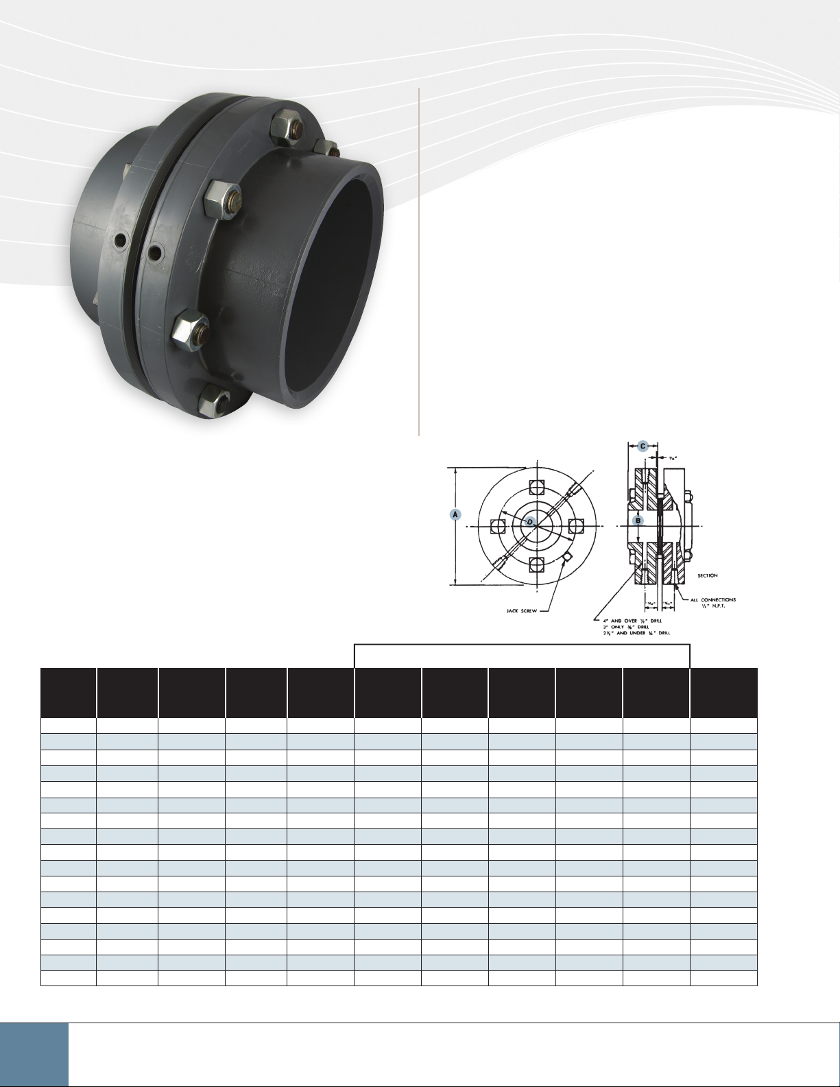
Model 952
Orice Flanges
Meriam raised face orice ange unions are designed
to provide a convenient, accurate method for installing
orice plates. They incorporate accurately positioned
pressure taps for connecting the ow measuring
instruments. This eliminates the requirement of
locating pressure taps in the eld. Improper location
of these taps will result in poor accuracy of the ow
measuring system. These built-in taps also reduce eld
installation labor necessary for welding, drilling and/
or tapping pressure taps on the ow line itself. Meriam
orice anges are provided complete with nuts, bolts,
gaskets and plugs for installation with no other parts
required.
Model 952 FS 30 - forged steel, slip-on welding; 300 lb. raised face
For systems where welded connections are required. These anges
are slipped over the pipe which is brought ush with the ange face.
The pipe is then welded to the ange.
Line
Pipe
Size
1 4
1¼ 5¼ 1
1½ 6
2 6½ 2
2½ 7½ 2
3 8¼ 3
4 10 4
5 11 5
6 12½ 6
8 15 8
10 17½ 10
12 20½ 12
14 23 14
16 25½ 16
18 28 18
20 30½ 20
24 36 24
All Dimensions are in inches
Flange
O.D.
A
7
8
/
1
8
/
Bore Dia.
B
3
8
1
/
23
32
/
31
32
1
/
7
16
/
15
16
/
9
16
/
9
16
/
21
32
/
23
32
/
23
32
/
7
8
/
7
8
/
3
16
/
3
16
/
3
16
/
3
16
/
3
16
/
Hub
Length
C
7
8
1
/
13
16
1
/
7
8
1
/
15
16
1
/
2 5
1
16
2
/
1
8
2
/
1
8
2
/
1
8
2
/
7
16
2
/
5
8
2
/
7
8
2
/
Dia.
Raised
Face
13
16
2
/
3
16
3
/
11
16
3
/
5
16
4
/
1
16
/
13
16
5
/
1
16
7
/
3
8
8
/
No. of
Holes
4
4
4
8
8
8
8
8
9¾ 12
12 12 1
1
8
14
/
16 1
16½ 16 1¼ 1
3 19 20 1¼ 1
1
30
8
/
3
8
/
5
8
/
3
8
/
20 1
24 1
24 1
24 1
3¼ 21
3½ 23
3¾ 25
3
16
4
/
Drilling Template
Dia. of
Holes
11
16
/
11
16
/
13
16
/
11
16
/
13
16
/
13
16
/
13
16
/
7
8
/
7
8
/
1
8
/
3
8
/
3
8
/
3
8
/
5
8
/
Dia. of
Bolts
5
8
/
5
8
/
¾
5
8
/
¾
¾
¾
¾
¾
7
8
/
1 5¼ 15¼ 196 lbs.
1
8
/
1
8
/
1¼ 6¼ 22½ 620 lbs.
1¼ 6½ 24¾ 691 lbs.
1¼ 6¾ 27 781 lbs.
1½ 7½ 32 1201 lbs.
Length of
Bolts
Bolt
Circle
D
4 3½ 15 lbs.
7
4 3
8
/
4¼ 4½ 19 lbs.
4 5 23 lbs.
7
4¼ 5
4¼ 6
4¼ 7
8
/
5
8
/
7
8
/
4¼ 9¼ 70 lbs.
5
4¼ 10
8
/
4½ 13 134 lbs.
5½ 17¾ 281 lbs.
5¾ 20¼ 380 lbs.
Approx.
Union
Weight
17 lbs.
31 lbs.
39 lbs.
60 lbs.
100 lbs.
86
Meriam Process Technologies www.meriam.com ph: 800.817.7849 fax: 216.281.0228
Page 2
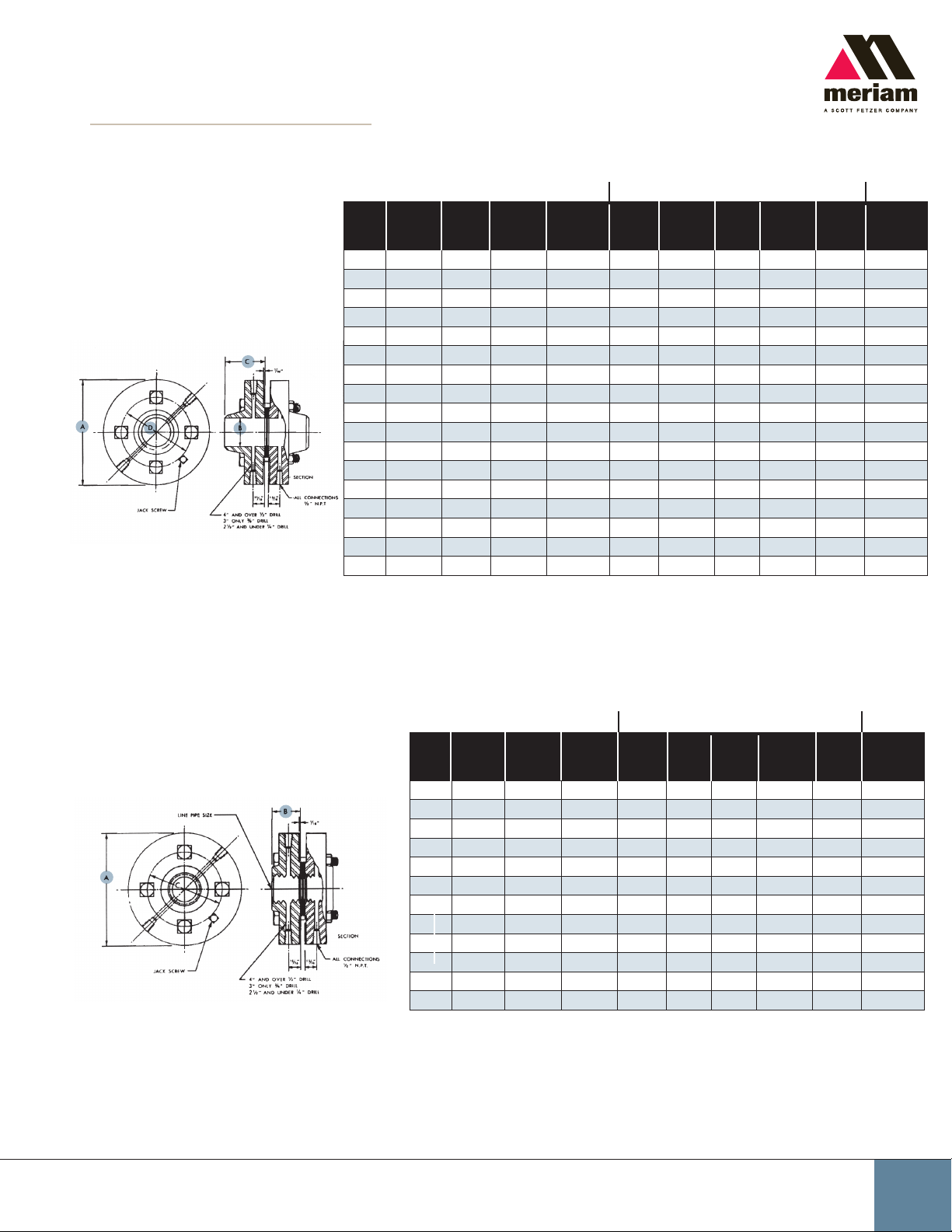
Model 952
Orice Flanges
Model 952 FW 30 - forged steel, welding
neck; 300 lb. raised face
Similar to slip-on welding model but for
use where weld neck is preferred. These
anges are butted up against the ends of
the pipe and welded in place.
Line
Flange
Pipe
Size
1 4
O.D.
A
7
8
/
1¼ 5¼ 1
1
1½ 6
8
/
2 6½ 2
2½ 7½ 2
3 8¼ 3
4 10 4
5 11 5
6 12½ 6
8 15 8
10 17½ 10
12 20½ 12
14 23 14
16 25½ 16
18 28 18
20 30½ 20
24 36 24
Bore
Dia.
B
3
1
/
23
/
31
1
/
7
16
/
15
/
9
16
/
9
16
/
21
/
23
/
23
/
7
/
7
/
3
/
3
/
3
/
3
/
3
/
Hub
Length
C
7
8
1
/
13
32
1
7
32
1
/
15
1
16
2 5
1
2
/
1
2
/
1
32
2
/
1
32
2
/
7
32
/
2
5
8
2
7
8
2
/
16
3 19 20 1¼ 1
16
3¼ 21
16
3½ 23
16
3¾ 25
3
16
4
/
Dia.
Raised
Face
8
2
16
/
3
8
3
16
/
4
16
5
8
7
8
8
8
9¾ 12
16
8
/
14
8
16½ 16 1¼ 1
16
30
No. of
Holes
13
16
/
3
16
/
11
16
/
5
16
/
1
16
/
13
16
/
1
16
/
3
8
/
12 12 1
1
8
/
16 1
1
8
/
3
5
3
20 1
8
/
24 1
8
/
24 1
8
/
24 1
4
4
4
8
8
8
8
8
Drilling Template
Dia.
Dia. of
Holes
11
16
/
11
16
/
13
16
/
11
16
/
13
16
/
13
16
/
13
16
/
7
8
/
7
8
/
1
8
/
3
8
/
3
8
/
3
8
/
5
8
/
Length
of
Bolts
5
/
5
/
¾ 4¼ 4½ 19 lbs.
5
/
¾ 4¼ 5
¾ 4¼ 6
¾ 4¼ 7
¾ 4¼ 9¼ 70 lbs.
¾ 4¼ 10
7
/
1 5¼ 15¼ 196 lbs.
1¼ 6¼ 22½ 620 lbs.
1¼ 6½ 24¾ 691 lbs.
1¼ 6¾ 27 781 lbs.
1½ 7½ 32 1201 lbs.
of
Bolts
8
4 3½ 15 lbs.
8
4 3
8
4 5 23 lbs.
8
4½ 13 134 lbs.
1
8
/
5½ 17¾ 281 lbs.
1
8
/
5¾ 20¼ 380 lbs.
Bolt
Circle
D
7
8
/
7
8
/
5
8
/
7
8
/
5
/
8
Approx.
Union
Weight
17 lbs.
31 lbs.
39 lbs.
60 lbs.
100 lbs.
Model 952 FT 30 - forged steel, threaded; 300 lb. raised face
Designed for systems where threaded connections are
suitable and conditions require forged steel.
All Dimensions are in inches
Line
Flange
Pipe
O.D.
Size
1 4
1¼ 5¼ 1
1½ 6
2 6½ 1
Hub
Length
A
7
/
1
/
B
8
8
7
8
1
/
13
16
/
7
8
1
/
15
16
/
2½ 7½ 2 5
1
3 8¼ 2
4 10 2
5 11 2
6 12½ 2
8 15 2
10 17½ 2
12 20½ 2
16
/
1
8
/
1
8
/
1
8
/
7
16
/
5
8
/
7
8
/
Drilling Template
Dia.
Raised
Face
2
3
5
No. of
Holes
13
16
/
3
16
3
/
11
16
/
5
16
4
/
1
16
/
13
16
/
1
16
7
/
3
8
8
/
9¾ 12
12 12 1
1
8
14
/
16½ 16 1¼ 1
Holes
4
4
4
8
8
8
8
8
16 1
Dia.
of
11
/
11
/
13
/
11
/
13
/
13
/
13
/
7
/
7
/
1
/
16
16
16
16
16
16
16
8
8
8
Dia.
of
Bolts
5
8
/
5
8
/
Length
of
Circle
Bolts
4 3½ 15 lbs.
4 3
Bolt
C
7
/
Approx.
Union
Weight
8
¾ 4¼ 4½ 19 lbs.
5
8
/
¾ 4¼ 5
¾ 4¼ 6
¾ 4¼ 7
4 5 23 lbs.
7
8
/
5
8
/
7
8
/
¾ 4¼ 9¼ 70 lbs.
5
¾ 4¼ 10
7
8
/
4½ 13 134 lbs.
8
/
100 lbs.
1 5¼ 15¼ 196 lbs.
1
8
/
5½ 17¾ 281 lbs.
17 lbs.
31 lbs.
39 lbs.
60 lbs.
Orice Plates & Accutubes
87
 Loading...