

Page 1

Reference
guide
PROVISIONAL
Page 2

No part of this documentation may be reproduced in any form whatsoever or be stored in
any data retrieval system without prior written permission of the copyright owners.
This documentation is supplied on an as-is basis. Information contained within this documentation is subject to change at any time without notice and must not be relied upon.
All company and product names are ™ or Registered Trademarks ® of their respective
owners. Windows Vista, Windows XP and Windows 2000 are trademarks of Microsoft Corporation.
Merging Technologies makes no warranties express or implied regarding this software, its
quality, performance, merchantability or fitness for a particular purpose. The software is
supplied “as is” you, the purchaser, are assuming the entire risk of the results of using this
Merging Technologies software.
In no circumstances will Merging Technologies, its owners, directors, officers, employees
or agents be liable to you for any consequential, incidental or indirect loss or damages
including loss of time, loss of business, loss of profits, loss of data or similar resulting from
the use of or inability to use the Merging Technologies hardware and or software or for
any defect in the hardware software or documentation.
© Copyright Merging Technologies Inc. 2007. All rights reserved
Merging Technologies
Le Verney 1070 Puidoux Switzerland
Tel: +41 21 946 04 44 • Fax: +41 21 946 04 45
www.merging.com
Page 3

- 3
:
Contents 3
1 Introduction 8
Scope 8
Other Documents 9
Terminology 9
Panels 10
The Basics 11
How to turn your Ramses On 11
How to turn your Ramses Off 11
How to load your project 11
Tips and tricks 11
2 Ramses Setup 12
Scope 12
Setup 13
Configure sub-menu 16
3 Fader Panel 22
Overview 22
Fader Strip 23
4 EQ Panel 24
Overview 24
EQ Aux and Pan Strip 25
EQ Summary. 28
EQ Fan Spoke Values 28
5 Monitor Panel 29
Monitor Setup in Pyramix 37
External Sources in Pyramix 38
Talkback in Pyramix 38
Meter Bridge Setup in Pyramix 38
6 Expert Panel 39
Expert Panel Overview 40
7 Upper Active Panel 56
8 Lower Active Panel 59
9 Pyramix Monitor Section 62
Contents
Page 4

- 4
:
Monitor ! Window 62
Scope 62
Monitor ! page 63
Speaker Sets 64
Configure page 66
Commands 67
Media Manager Monitoring 69
External Metering 70
External Inputs 71
Adding an External Machine 71
Talkback 72
Setting Up 73
Foldback 79
10 Meter Bridge 80
Scope 80
Meter Bridge Switch 80
Meter Bridge Window 81
Configuring the Meter Bridge 82
Automation Fader Mode and Group Indicators 85
11 Edit Bay 86
Introduction 86
Scope 86
Software Versions 86
General Overview 87
The Editor 88
Navigation 88
Modifiers - Left-hand Side 89
Modifiers - Right-hand side 89
Editor - Left-hand side 90
Editor - Right-hand side 91
Track Selection and User Keys 92
View and Modifiers 92
12 Pyramix Mixer 93
Overview 93
Mixer Pages 93
Configure Page 94
Settings 94
Page 5

- 5
:
Strip and Bus operations 96
Effect Management 98
External Effects Inserts 100
Organize Page 101
Route Page 102
Automate Page 103
Mix ! 104
Mixer Components 107
Input Strips 107
Mixing/Monitoring/Aux Busses 107
Groups 110
Channel Direct Outputs 110
Strip & Bus Channel Types 110
Basic Strip 116
Creating and Configuring Mixers 117
Mixer Configuration Wizard 118
I/O Busses Explained 119
Input Strip Types 119
Internal Return Busses 119
Mixer Delay Compensation 120
Summary 120
Delay Compensation Switching 120
Delay Compensation 121
Configuring a Blank or Existing Mixer 124
Adding Strips 124
Mixer I/O Assignments 124
Plug-ins 125
Further Mixer Configuration Options 126
Dithering Options 128
Mixer Presets 129
Mixer Surround Components 130
Surround Control window 131
13 Strip and Bus Tools 135
Strip and Bus Tools 135
Eq, Comp/Limiter/Expander 135
Sections 138
Common Features 138
Bus Tools 145
Delay Compensation 147
Delay Compensation / Pre-Anticipation 150
Page 6

- 6
:
14 Pyramix Mixer Settings 151
Mixer 151
Level Meter 151
DSP Power Saving 153
Mixer Settings 154
Plug-ins Settings 155
Index 156
Page 7

Ramses MSC reference guide
7
Ramses MSC reference guide
Document number: 10-03
Date: 12-December-2007
Page 8

Introduction
1 - 8
Ramses MSC reference guide
Introduction : Scope
1 Introduction
The Ramses MSC comes in two different chassis types and three models (8, 16 and 24
faders) plus an optional Edit Bay and the ARC.
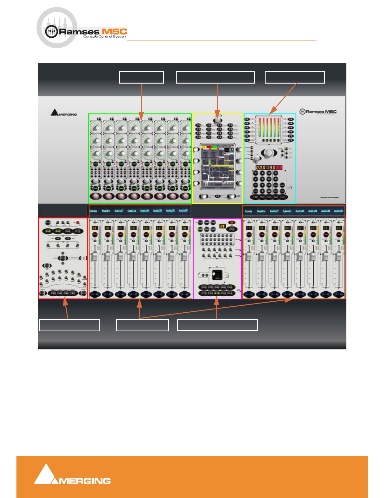
To aid understanding we have named the various Ramses panels:
• Fader Panel = per 8 faders
• EQ Panel = per 8 channels including Aux and Pan
• The Monitor Panel = Monitoring Section and Transport Bar
• The Expert Panel = Navigation, Automation, grouping.
• The Upper Active Panel = System management, Active Screen (TFT Touch)
• The Lower Active Panel = Master routing Panel, quick transport and locators
• Meter Bridge = A Pyramix window which provides a Meter Bridge
for the Ramses MSC. This can be viewed on any
monitor connected to the Pyramix workstation.
Options
• Edit Bay = Pyramix Editor Remote including a Transport Bar
• ARC = 48 Channels or 72 Channels depending on the
Ramses Chassis
Scope
This manual is written for Ramses Consolesoft version 1.5.3 3572 with firmware 1.5.2.31 in conjunction
with Pyramix version 6.0 and although most of what is outlined here will be relevant to other versions of
the software, please check to see if a more recent of this document exists on the Merging website.
Document Organisation
This document is organised mainly by control groupings, so if you are mystified as to the function of a given
control, please refer to the chapter that describes the panel it is located on and then cross-reference the
number printed on the panel image at the beginning of the chapter to locate the description for that control.
All Contents and Index entries and cross-references including the numbers referred to in the
previous paragraph are hyperlinks. Just click on them to jump to the information.
Updating
Please refer to the Ramses MSC Software Upgrade Guide for detailed information on upgrading your
firmware, Consolesoft and Edit Bay Sets.
Latest updates of Ramses and Pyramix
We strongly advise checking at:
www.merging.com/ramses/download
Page 9

Introduction
1 - 9
Ramses MSC reference guide
Introduction : Terminology
for the latest Pyramix and Ramses software and firmware versions or contacting your local merging Technologies Sales Partner who will help provide you with updates.
Other Documents
For a more task orientated, 'how to', manual, please refer to the Ramses Tutorial Guide.
http://www.merging.com/ramses/download/
Here you will also find further documents retaining to installing and operating RamsesMSC and Pyramix.
Terminology
In all Ramses MSC documentation we use the following terms:
Virtual Strip A mixer control Strip on the Pyramix Virtual Mixer that can be controlled and
displayed by the physical controls on the Ramses MSC. Strip types include
Inputs, Mix, Sub-Group and Aux Bus Masters and Control Groups.
Slot or Physical Control Strip
Each Slot is a vertical group of physical controls, including a fader, on the
Ramses MSC surface. You will have either 8,16 or 24 of these, depending on
the model and configuration of your console. A Slot can have any Virtual
Strip selected to it.
Ergonomic Spread An arrangement of virtual Mixer Strips assigned to Slots. Ergonomic
Spreads can be stored, recalled, modified etc…
Touch (Screen) Button Refers to a Virtual Button. I.e. an area of the touch screen that must be
touched to perform a function, not a hardware button.
Expert Panel Includes all controls concerned with Navigation, Automation, Copy/Paste
of Settings, Grouping and Ergonomic Spreads.
Monitor Panel Monitoring Section and Transport Bar
Upper Active Panel System management, Active Screen (TFT Touch)
Lower Active Panel Master Routing Panel, Joystick Panner, Quick Transport and Locators
Iggy Is the name of the Ramses MSC software application and interface shown on
Active Screen
Consolesoft Files containg Iggy software
Firmware Files for programming Hardware upgrades (flash)
Consolesoft Sets Files containing Edit Bay mappings
Page 10
Introduction
1 - 10
Ramses MSC reference guide
Introduction : Panels
Panels
FADER PANEL
EQ PANEL UPPER ACTIVE PANEL
LOWER ACTIVE PANEL
MONITOR PANEL
EXPERT PANEL
Ramses MSC Panels
Page 11
Introduction
1 - 11
Ramses MSC reference guide
Introduction : The Basics
The Basics
How to turn your Ramses On
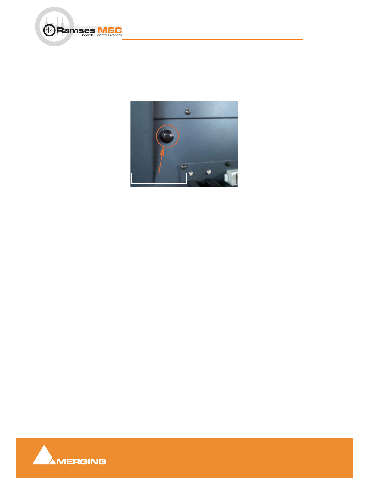
Assuming the Console has been correctly installed and is plugged into mains power, simply press the
black 'ON' button to power on the console. The switch can be found on the rear panel on the left-hand side
when viewed from the back:
The boot process takes approximately one to two minutes.
How to turn your Ramses Off
Press the SYSTEM Button on the Upper Active Panel, then press the SHUTDOWN Touch Button then con-
firm by pressing the CONFIRM Touch Button.
How to load your project
Once your Ramses has booted, you will be able to load a project in Pyramix and start mixing.
Note: it is important that the console is fully powered up before you load your project.
The Pyramix project you load will determine the number and type of the features you will be able to map to
your Ramses. For example, the number of mixer strips, tracks and plugins, whether there is a monitoring
section etc.
At any time you may add or remove strips, tracks, buses, plugins etc. and the Ramses will reconfigure in
seconds.
Tips and tricks
We strongly recommend setting up some templates on your Pyramix/Masscore that include everything you
need in your day to day work, since MassCore has tremendous power (256 I/O and 256 Busses). This will
avoid the inconvenience of mixer rebuilds. Treat the Ramses as you would a normal, fixed architecture console with a full complement of Dynamics, EQ's and effects etc. and just switch the functions on as you need
them.
POWER SWITCH
Power Switch
Page 12
Ramses Setup
2 - 12
Ramses MSC reference guide
Ramses Setup : The Basics
2 Ramses Setup
Scope
Setting up a Ramses MSC is very simple. Once you have installed it and connected it with Pyramix we
strongly advise you to work through this Setup section since every Ramses has specific features such as
the number of faders, whether an Edit Bay is present etc.
Setting up Ramses with Pyramix
Please refer to the Ramses Install Guide available at:
www.merging.com/ramses/download
Upgrading Ramses Software and Firmware
Please refer to the Ramses Upgrade Guide available at:
www.merging.com/ramses/download
Page 13
Ramses Setup
2 - 13
Ramses MSC reference guide
Ramses Setup : The Basics
Setup
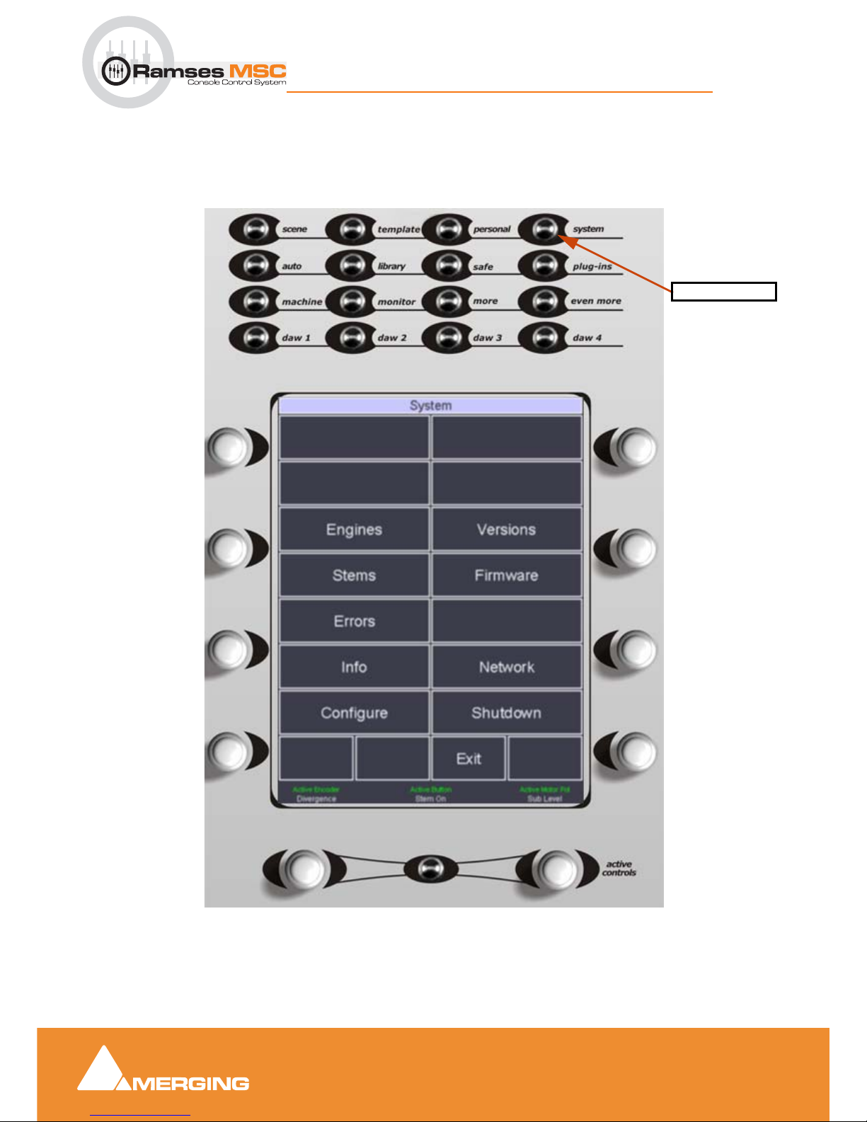
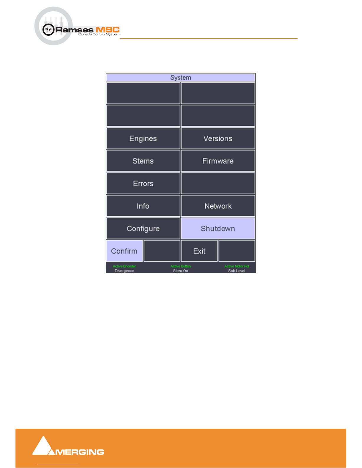
On the Upper Active Panel press the system button to access the System menu with the following
choices. You can access the System menu at any time from any page by pressing the system button
Each Touch Button performs and action, displays information or opens the associated sub-menu. Where
there are blanks, these are available for future expansion:
Active Screen - System Page
system button
Page 14

Ramses Setup
2 - 14
Ramses MSC reference guide
Ramses Setup : The Basics
Engines
Opens the Engines page. All engines currently installed are listed and can be restarted from here.
Stems
Description to follow.
Errors
Displays a log file in the unlikely event of errors.
Info
Lists all the software versions installed currently along with the sub-module versions specific to this console.
Configure
Opens the Configure sub-menu
Versions
Opens the Ver sions page. I.e. this is where you can load an alternative version of the ConsoleSoft appli-
cation or install a new one. Also where sets (configuration files) for the optional Edit Bay are installed and
loaded.
Please see the Ramses MSC upgrade guide for details.
Firmware
Opens the Firmware page. All Firmware versions currently available in the console are listed and can be
installed from here. Also, new versions of Firmware are imported into the console from this sub-menu.
Please see the Ramses MSC upgrade guide for details.
Network
Opens the Network page. This is where the Network connection is configured.
Please see the Ramses MSC install guide for details.
Page 15
Ramses Setup
2 - 15
Ramses MSC reference guide
Ramses Setup : The Basics
Shutdown
Initiates the Shutdown sequence for the console. The Confirm Touch Button appears. Press this to begin
console Shutdown.
Exit
Exits the System menu and returns to the screen displayed prior to entering the Setup menu.
Page 16
Ramses Setup
2 - 16
Ramses MSC reference guide
Ramses Setup : The Basics
Configure sub-menu
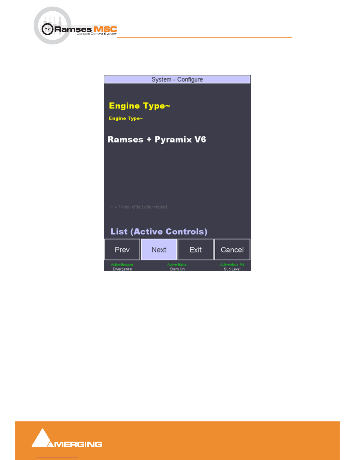
The Configure sub-menu has a number of pages. Pages are located by pressing the Next and Previous
Touch Buttons. Since this is Page 1 only the Next button is available
The name of the current page is shown in yellow at the top of the screen. The
~ symbol indicates that
changes made on this page will only take effect after a console restart.
The available options are listed below in white.
The label in lilac at the bottom of the screen above the buttons indicates which parameter(s) can be changed and which physical controls may be used to change it. (In this case the Active Controls below the screen may be used to navigate the list)
Active Screen - Configure Page 1
Page 17
Ramses Setup
2 - 17
Ramses MSC reference guide
Ramses Setup : The Basics
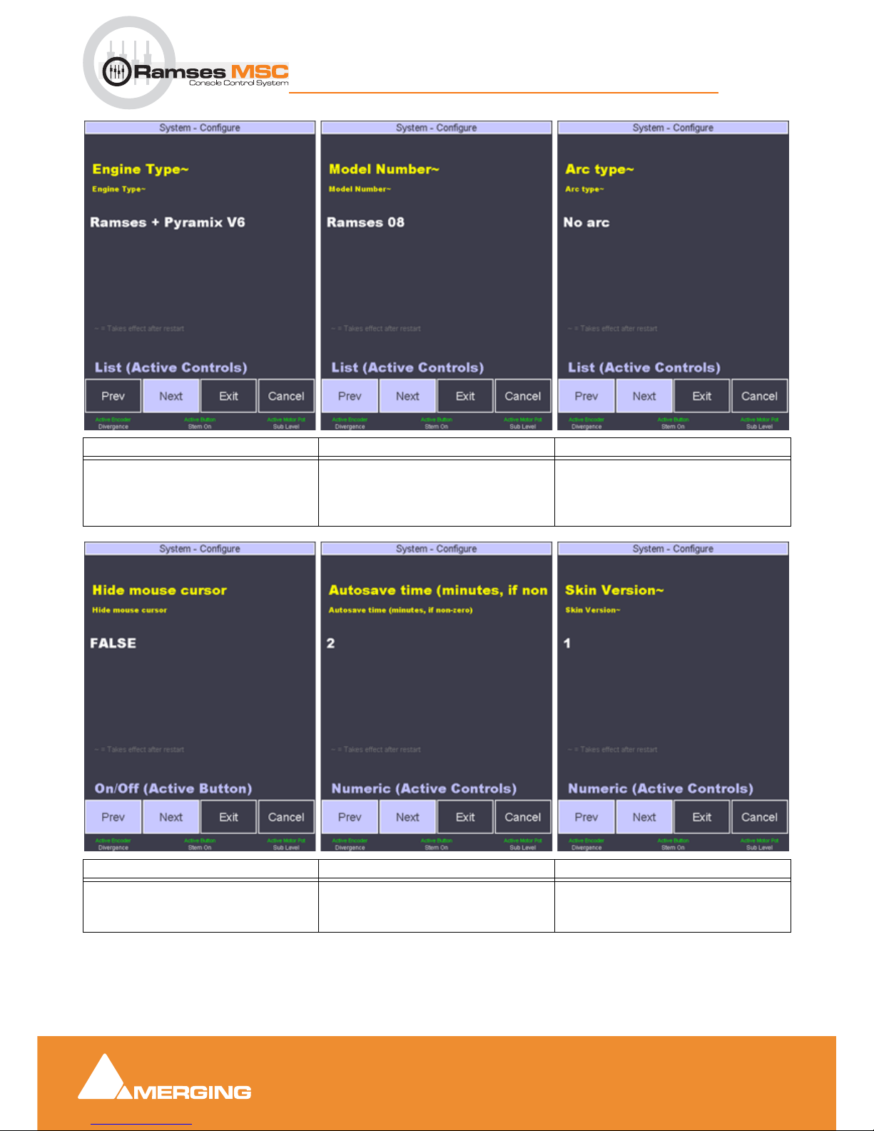
Page 1 Page 2 Page 3
Pyramix 5 or 6 In most cases set this
to V6 (MassCore)
Number of physical faders 8 - 16 - 24 ARC Option
- No ARC
- Arc 48
- Arc 72
Page 4 Page 5 Page 6
Hide Mouse Cursor within Iggy
- TRUE
- FALSE
Autosave time interval for Ramses
templates
In minutes if not zero
Iggy Skin Version (appearance)
- 0 (not recommended)
- 1 (recommended)
Page 18
Ramses Setup
2 - 18
Ramses MSC reference guide
Ramses Setup : The Basics
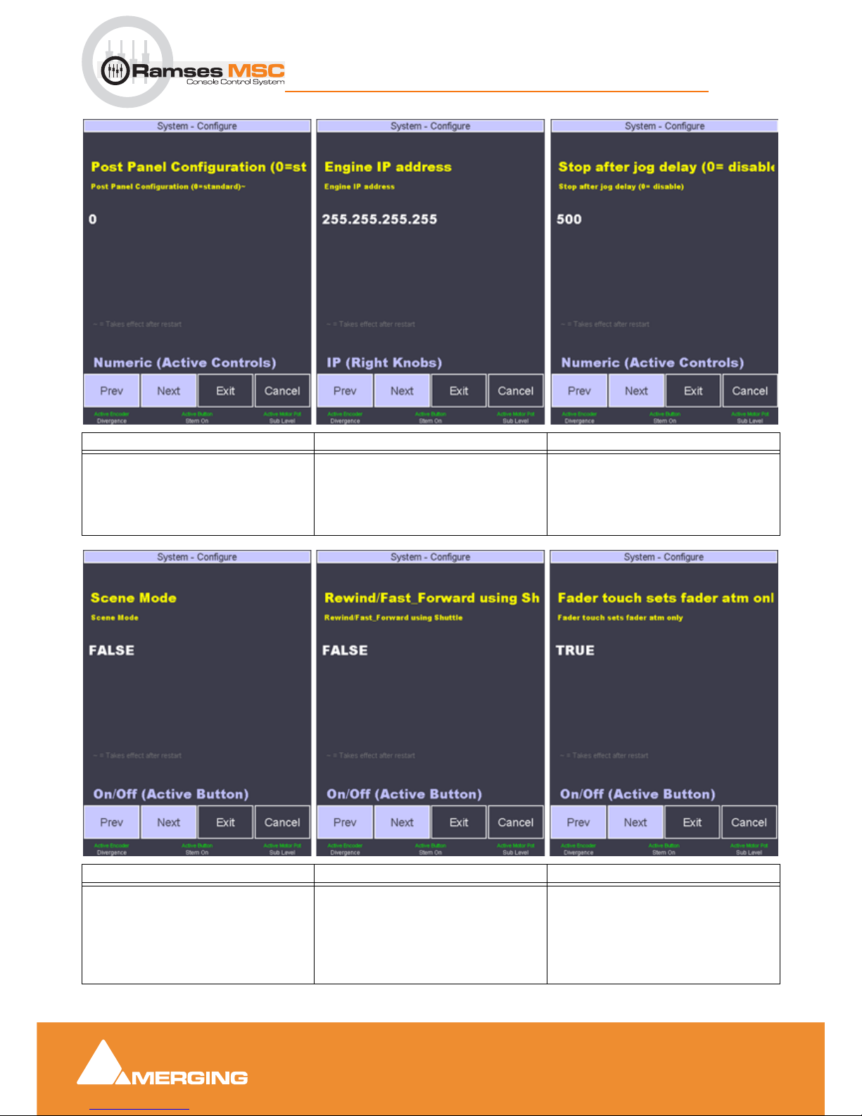
Page 7 Page8 Page 9
Edit Bay configuration
0 is default
1 - 9 are User Sets
Engine IP address = Pyramix IP
address
System > Network shows Ramses IP
address
Sets the time after last jog event after
which jog is canceled and Stop
invoked
0 - disable
1 - X seconds
Page 10 Page 11 Page 12
Scene Mode for Theatre Use
(future implementation)
- FALSE
- TRUE
Change Shuttle backwards and forwards commands to REWIND and
Fast Forward
- FALSE
- TRUE
When TRUE automation in a strip is in
independent by section. (fader, auxes
EQ etc.) When False Entire strip
changes status with fader
- TRUE
- FALSE
Page 19
Ramses Setup
2 - 19
Ramses MSC reference guide
Ramses Setup : The Basics
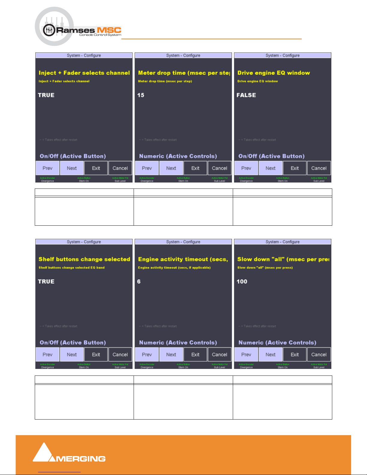
Page 13 Page 14 Page 15
Selects channel to Active Screen when
Inject or fader is touched
- TRUE
- FALSE
Meter fall-back time for all Ramses
Meters
in milli-seconds per step
Show/Hide plug-ins on Pyramix screen
(only Strip Tools at present)
- TRUE
- FALSE
Page 16 Page 17 Page 18
Buttons immediately above and below
EQ rotaries switch between Shelf and
band-pass OR toggle selected band.
- TRUE
- FALSE
N/A at present Changes the ALL button behaviour
from momentary to latch for the time
set here per press.
Obviates necessity to hold down ALL
button when applying e.g. Unity Gain
Page 20
Ramses Setup
2 - 20
Ramses MSC reference guide
Ramses Setup : The Basics
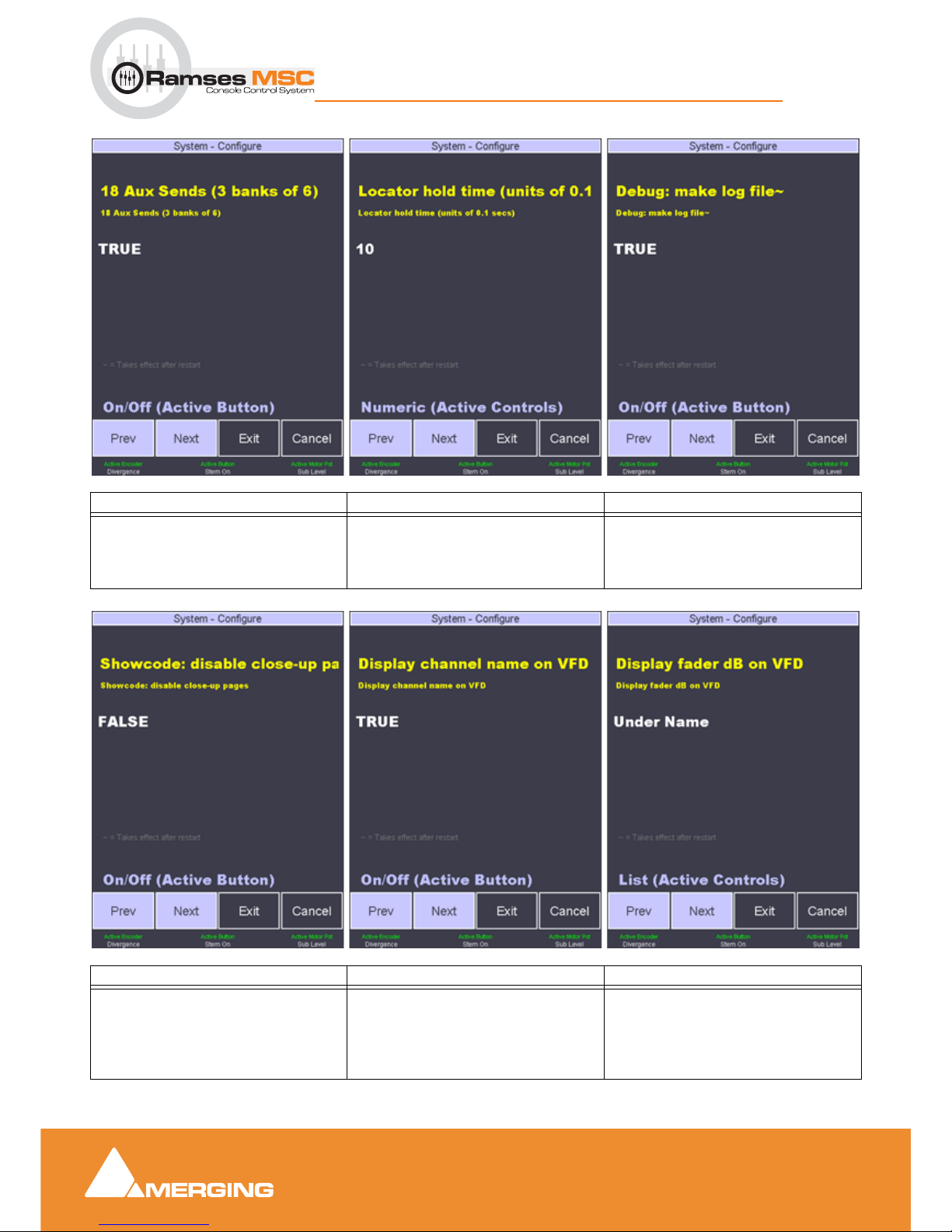
Page 19 Page 20 Page 21
Toggles between 18 independent
AUXs or three banks of 6 (A, B, C)
- TRUE
- FALSE
Sets the length of time you have to
hold a locator button (Lower Active
Panel below Transport) to store the
current value. In 100msec increments
In the inlikely event of a Ramses failure, create a log file
- TRUE
- FALSE
Page 22 Page 23 Page 24
Enable/Disable zoom into EQ, Dyn etc.
pages when touched in Active Screen
- TRUE (disable)
- FALSE (enable)
Display Strip name on Alphanumeric
display above the fader strip
- TRUE
- FALSE
Display current fader gain value in dB
on Alphanumeric display
- none
- under name
- above name
Page 21
Ramses Setup
2 - 21
Ramses MSC reference guide
Ramses Setup : The Basics
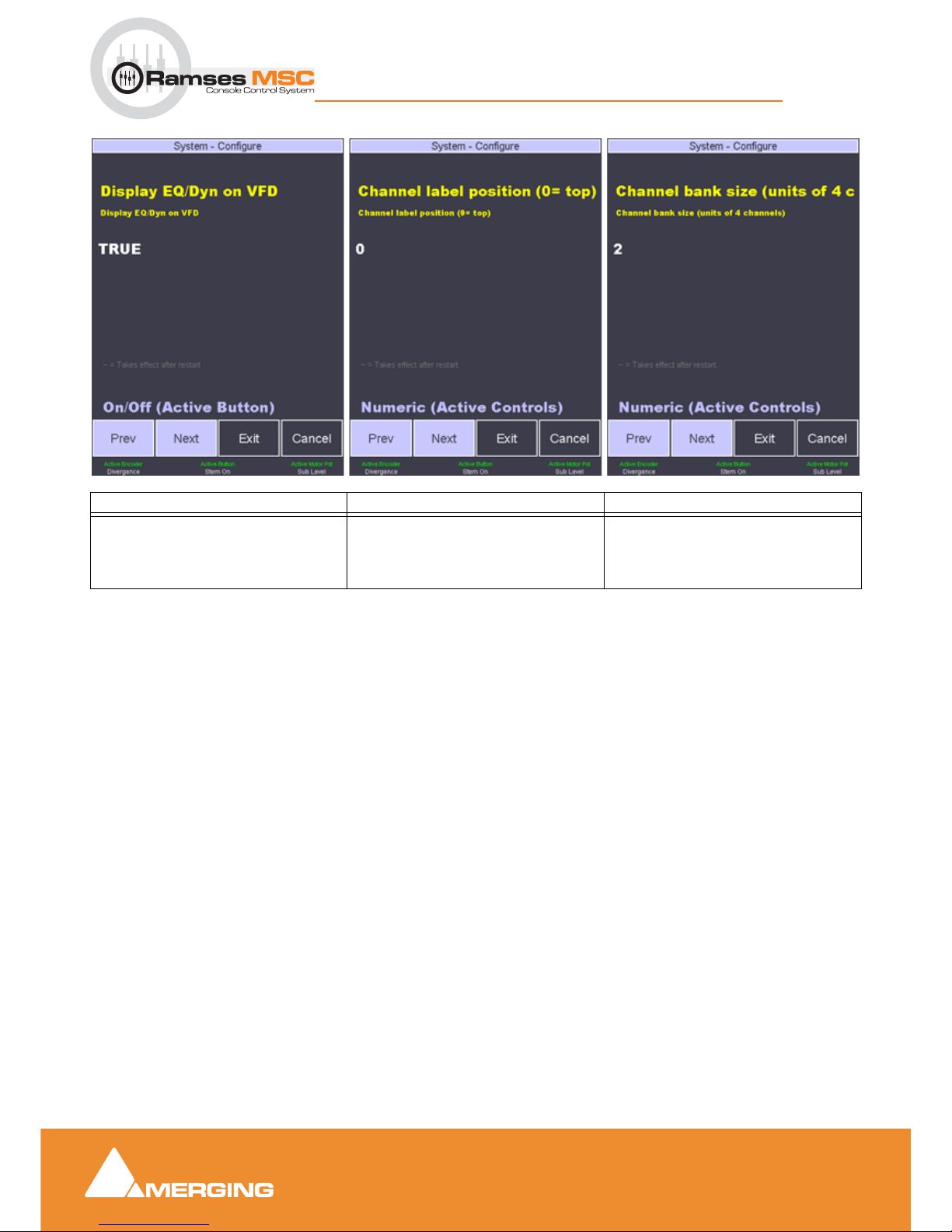
Page 25 Page 26 Page 28
Display EQ curve and Dynamics action
on Alphanumeric display
- TRUE
- FALSE
Strip Label position (If ON) on the
Alphanumeric display
0 = top
Number of Strips per Bank in 4 Strip
units
1 = 4 Strips per press of Bank R or L
2 = 8 Strips per press of Bank R or L
Page 22
Fader Panel
3 - 22
Ramses MSC reference guide
Fader Panel : Overview
3 Fader Panel
Overview
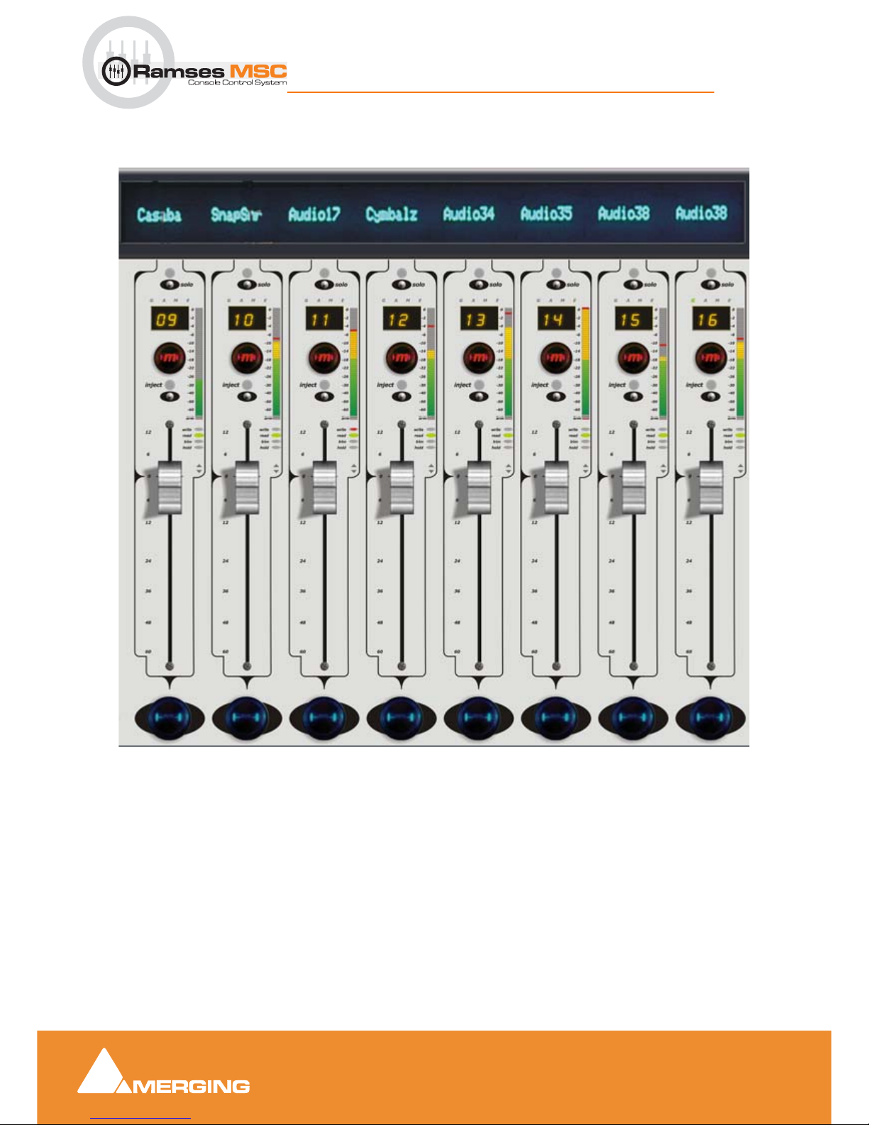
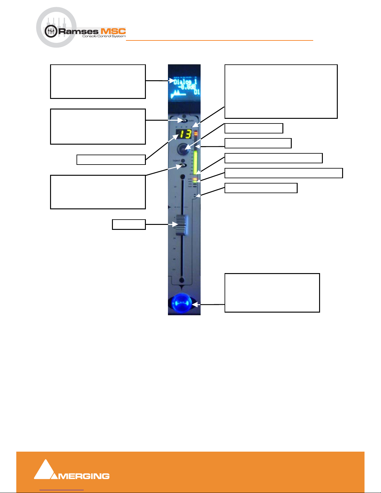
Each Fader Panel consists of 8 identical Fader Strips with an alphanumeric display at the top. Depending
on which model Ramses MSC you have, you will have one, two or three Fader Panels.
Fader Panel
Page 23
Fader Panel
3 - 23
Ramses MSC reference guide
Fader Panel : Fader Strip
Fader Strip
FADER DISPLAY
This usually shows you the channel
number or name and can display
other information depending on the
console mode such as EQ curves etc.
SOLO TOUCHPOINT AND
INDICATOR
Touch this to solo a channel. The indicator will light to indicate the channel
is in solo
CHANNEL TYPE INDICATORS
G is lit when channel is a Group VCA Master
within Pyramix project. (To be implemented)
A is lit when channel is a Aux Bus Master.
M is lit when channel is a Mix Bus Master.
E will be lit for future purposes
When none is lit - channel is normal audio
channel.
HOLD BUTTON
Press this button to lock this channel
in its slot.
It will now stay in place regardless of
Ergonomic Spread recall, undo, etc…
functions
INJECT TOUCH POINT
Touch this point and then, whilst holding it, swap channels, aux, busses,
paste EQ/dyn, track arm and many
other functions.
ARMED TRACK INDICATOR
CHANNEL METER
MUTE BUTTON
CHANNEL NUMBER
AUTOMATION STATE INDICATORS
NULL INDICATORS
FADER
Page 24
EQ Panel
4 - 24
Ramses MSC reference guide
EQ Panel : Overview
4 EQ Panel
Overview
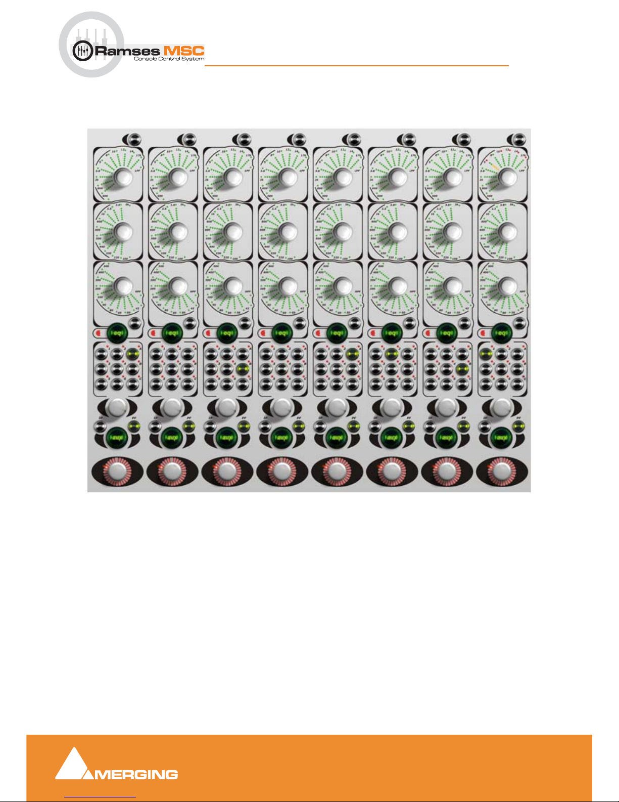
Each EQ Panel consists of 8 identical Strips. Depending on which model Ramses MSC you have, you will
have one or two EQ Panels.
EQ Panel
Page 25
EQ Panel
4 - 25
Ramses MSC reference guide
EQ Panel : EQ Aux and Pan Strip
EQ Aux and Pan Strip
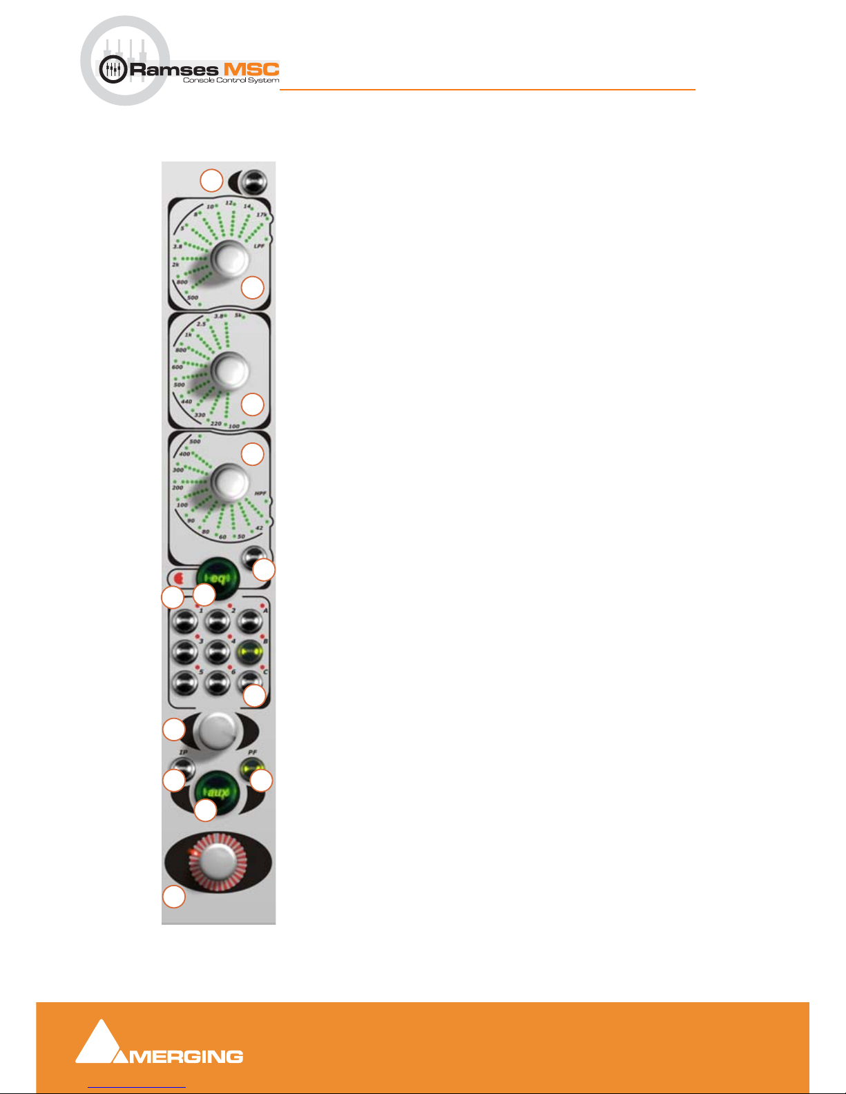
Each EQ Strip has a series of dedicated EQ controls. There are three Dual-concentric Encoders, the top of which control the gain and the bottom the frequency for
each band. The settings of each EQ band are displayed using the EQ Fans around
each encoderFor access to EQ controls additional to those on the channel strip,
such as Q, band in/out and Filter controls - use the Active Panel.EQ Strip Overview
1. shelf
2. HF band EQ dual-concentric encoder and display
3. MF band EQ dual-concentric encoder and display
4. LF band Eq dual-concentric encoder and display
5. shelf
6. Master eq
7. more indicator
8. aux select buttons
9. aux knob.
10.aux IP (In-Place) button
11. aux PF (Pre-Fade) button
12.aux on/off button
13. pan/balance knob
1
2
3
4
5
6
8
9
10 11
12
13
7
Page 26
EQ Panel
4 - 26
Ramses MSC reference guide
EQ Panel : EQ Aux and Pan Strip
1 shelf
The low pass shelf Button switches the top band of EQ to a shelving type filter. This also changes the EQ
Fan display to Shelving mode.
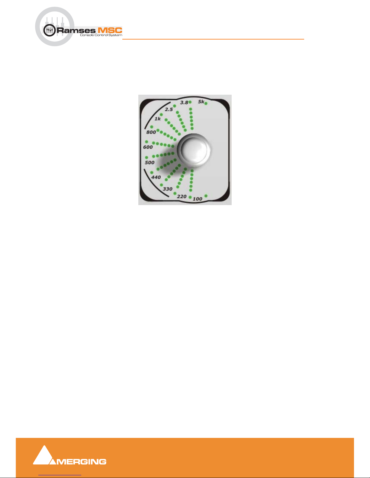
2,3 and 4 HF, MF and LF eq eq display
The three fan displays are very similar. The differences are:
• The frequency legends are appropriate to the band. However, the frequency range is the same as
the equaliser band being controlled. When the selected frequency cannot be displayed the out of
range indicator will light.
• The mid band has two out of range indicators. the low and high bands logically only have one
each.
• the ‘spare’ LED in the low and high bands is used to indicate HPF (High Pass Filter) and LPF (Low
Pass Filter) active.
5 shelf
The high pass shelf Button switches the bottom band of EQ to a shelving type filter. This also changes the
EQ Fan display to Shelving mode.
6 Master eq
The Master eq Button toggles the entire EQ section in/out of the signal path.
7 More Indicator
The 'More' Indicator is lit whenever there is more EQ applied than is displayed by the channel strip EQ controls - such as additional bands of EQ.
8 aux select
The aux Select section allows control over 12 discreet Aux Sends per channel (1 to 8 channels), and 6
Sends for N-1 Mixes and/or Talkbacks You can also see the settings for all Aux's on the Active Screen. The
sends are divided into into three banks (A,B,C) A & B are for standard Aux's and bank C is used for N-1
(mix minus) Mixes and talkback (please refer to the Monitor section of the Pyramix User Manual)
Page 27

EQ Panel
4 - 27
Ramses MSC reference guide
EQ Panel : EQ Aux and Pan Strip
9 aux knob
Controls the send level to the selected aux bus.
10 aux IP
When lit Aux will be sourced from the ‘In Place’ strip output including fader gain.
11 aux PF
When lit Aux is sourced pre-fader
12 aux on/off
Toggles selected Aux send on and off. On when lit.
13 pan
The pan encoder on the channel strip allows pan / balance control from left to right in the pan field. For surround panning, use the Joystick on the Active Panel. Please see: . Divergence and LFE controls can
also be updated from the Active Panel.
The channel strip pan encoders display surround information as well as the left to right position. There will
always be a single LED to indicate the left to right position - this LED travels from 9 o'clock to 3 o'clock
across the top of the encoder. If there is any front to back panning information, the bottom 5 LED's below
this line display the F-R position.
• If there is no front-to-back information, the bottom front-to-back LEDs will not be lit.
• If the pan position is all the way to the front, the bottom front-to-back LEDs will not be lit.
• If there is front-to-back information but the pan position is all the way to the left, only the left front-to-
back LED will be lit.
• If there is front-to-back information but the pan position is all the way to the right, only the right front-
to-back LED will be lit.
Note: For access to EQ controls additional to those on the channel strip, such as Q, band
in/out and Filter controls - use the Active Panel.
Page 28
EQ Panel
4 - 28
Ramses MSC reference guide
EQ Panel : EQ Aux and Pan Strip
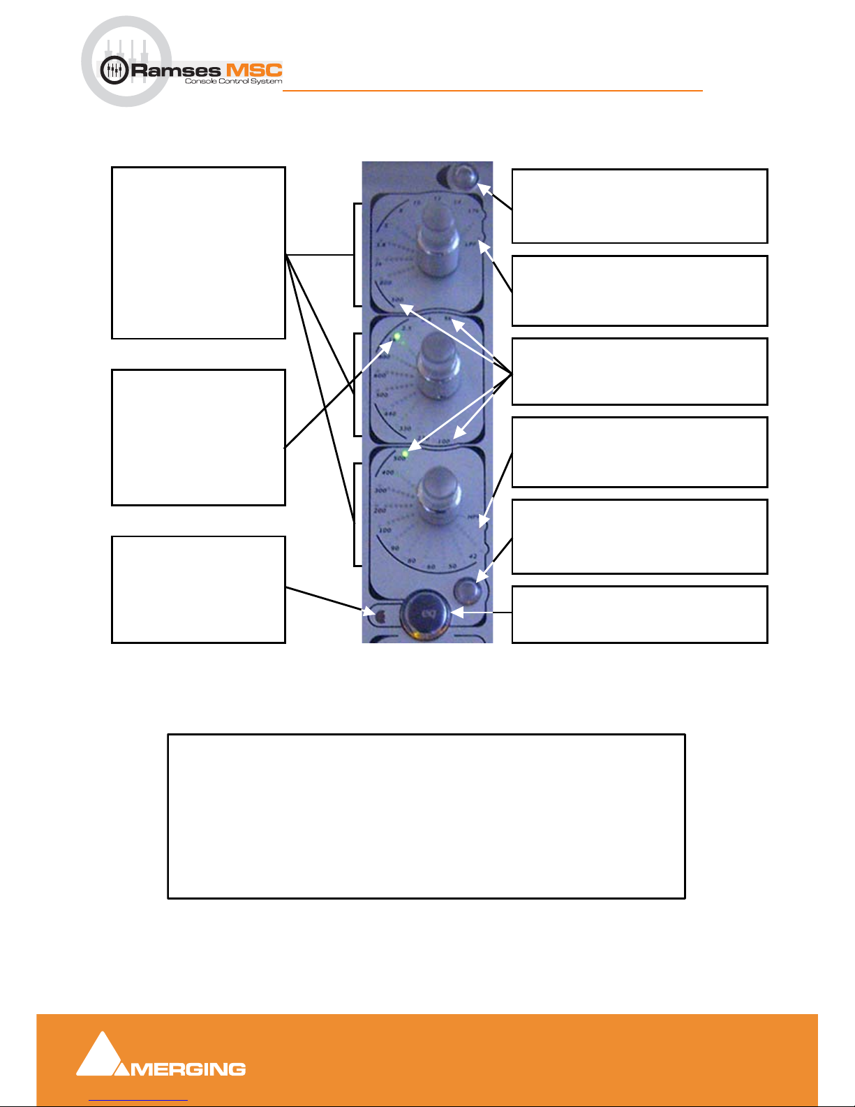
EQ Summary.
EQ Fan Spoke Values
EQ Fans
The number of LED's lit in
each “spoke” represents the
degree of cut or boost applied
by this band of EQ. When
cutting, the spoke grows from
the rim towards the centre of
the EQ Fan, when boosting
the spoke grows from the
centre towards the rim. The
exact amount of cut or boost
is displayed on the Active
Screen (see chart below).
Shelf
The low pass Shelving Button switches the
top band of EQ to a shelving type filter. This
also changes the EQ Fan display to Shelving
mode.
Shelf
The high pass Shelving Button switches the
bottom band of EQ to a shelving type filter.
This also changes the EQ Fan display to
Shelving mode.
Master EQ
The Master EQ Button toggles the entire EQ
section in/out of the signal path.
LPF Indicator
The LPF Indicator is lit whenever the LPF Filter is engaged - This parameter is controlled
through the Active Panel (see below).
Out of Range
The Out Of Range Indicators are lit when the
frequency selected is outside the EQ Fan's
display range.
Rim Light
A Rim Light is lit whenever
this band of EQ is engaged.
green indicates no cut/boost,
red indicates cut and yellow
indicates boost. Each spoke
is lit whenever the selected
frequency is the same as or
higher than the frequency
marked next to the spoke.
More Indicator
The 'More' Indicator is lit
whenever there is more EQ
applied than is displayed by
the channel strip EQ controls
- such as additional bands of
EQ.
HPF Indicator
The HPF Indicator is lit whenever the HPF Filter is engaged - This parameter is controlled
through the Active Panel (see below).
EQ Fan Spoke Display
No Spoke LEDs illuminated = No Cut or Boost Applied
1 Spoke LEDs illuminated = up to 1.99 dB Cut or Boost
2 Spoke LEDs illuminated = 2 to 3.99 dB Cut or Boost
3 Spoke LEDs illuminated = 4 to 5.99 dB Cut or Boost
4 Spoke LEDs illuminated = 6 to 9.99 dB Cut or Boost
5 Spoke LEDs illuminated = 10 to 14.99 dB Cut or Boost
6 Spoke LEDs illuminated = more than 15 dB Cut or Boost
Page 29
Monitor Panel
5 - 29
Ramses MSC reference guide
Monitor Panel : EQ Aux and Pan Strip
5 Monitor Panel
Note: If you are unfamiliar with the Pyramix Monitor Section Please see: .
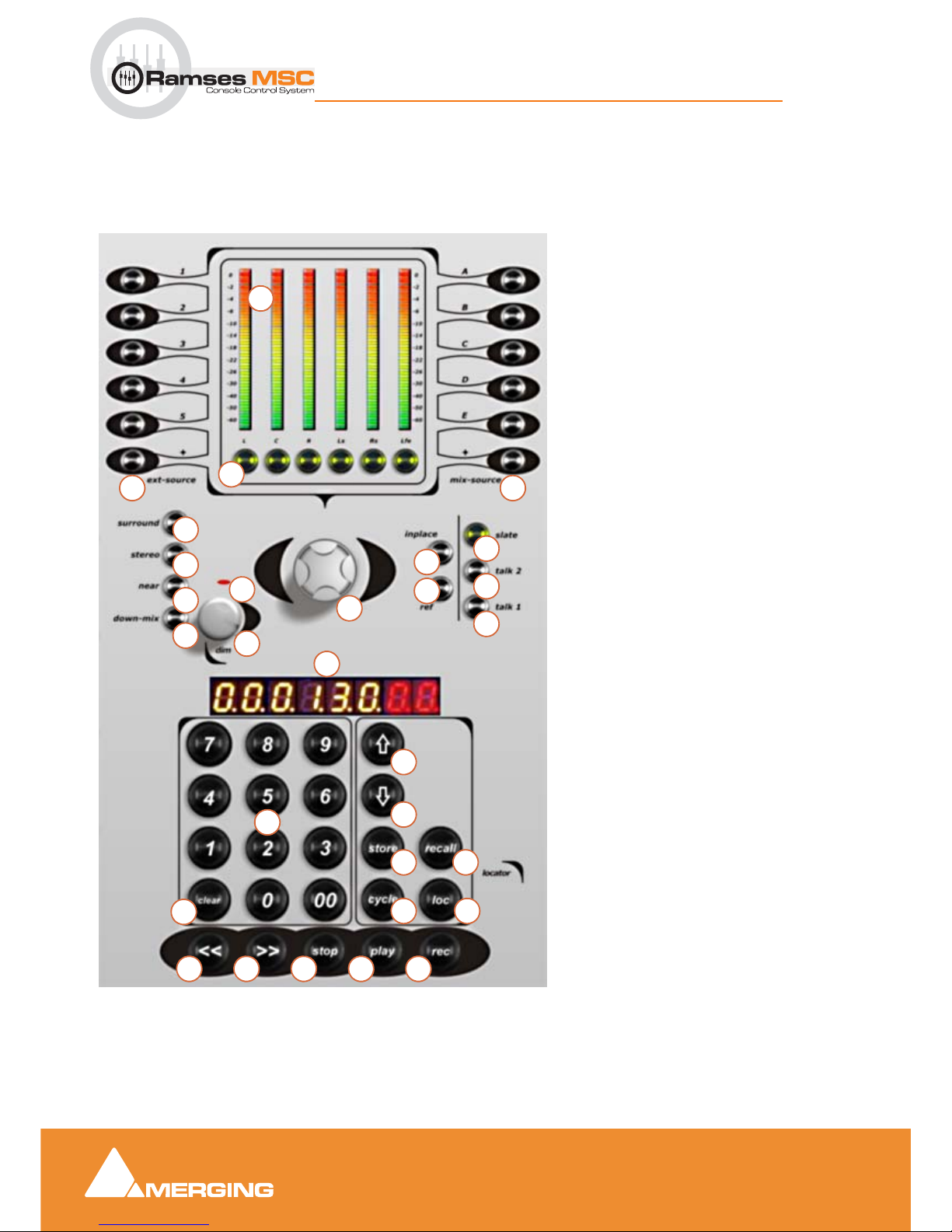
Monitor Panel Overview
Page No.
1. Bus Peak Meters
2. External Source select buttons
3. Mix Source select buttons
4. Monitor Mute buttons
5. surround speaker select
6. stereo speaker select
7. near speaker select
8. down-mix (toggle)
9. dim encoder and switch (press)
10. Dim indicator
11. Master Control Room Volume
12. inplace (solo)
13. ref level (monitors)
14. slate - Talkback - Slate button
15. talk 2 - Talkback 2 button
16. talk 1 - Talkback 1 button
17. TimeCode display
18. Display Offset button
19. Mark TimeCode location button
20. store TimeCode location button
21. cycle Mode button
22. recall TimeCode location button
23. loc 'Locate to' button / Scene loc
24. Numeric Keypad (not Pyramix)
25. clear TimeCode display button
26. << - Rewind button
27. >> - Fast Forward button
28. stop button
29. play button
30. record button
Monitor Panel
28 29 302726
25
23
22
21
20
19
18
24
17
9
11
16
15
14
10
8
7
6
5
4
2 3
12
13
1
Page 30

Monitor Panel
5 - 30
Ramses MSC reference guide
Monitor Panel : EQ Aux and Pan Strip
1 Bus Peak Meters 1 - 6
The Bus Peak Meters display the levels of the Bus that is currently selected using the Monitor Mix Sources
(see page) or External Sources (see page ) buttons.
The bus elements are displayed, left to right, in the following order: Left, Centre, Right, Left Surround, Right
Surround, Sub (or LFE).
Thus, if
Mix Source A is selected, the Meters display the signals present on Mix Bus 1 as shown in Pyra-
mix monitoring from top to bottom. If External Source button 4 has been pressed, the Meters display the
signals present on External Source 4.
Note: since the Mix Source buttons are 'radio' buttons in a group with the External
Source buttons and exclusive, i.e. only one selection at a time is permitted, these Meters
will always be monitoring either a External Source or Mix Source signal.
Note: Since there are 6 Peak meters, when a stereo signal is selected, only the Left and
Right Peak Meters will be active.
2 External Sources 1 to 5 and “+”
External Sources 1 - 5 switch the monitors to monitor incoming signals from External Sources . The last
button "
+" cycles through all the available External Sources as defined and shown in the Pyramix Monitor.
The number of External Sources available for selection is defined by the number of External Sources Pyramix has been set up to monitor - if there are only three External Sources defined in the Pyramix Monitor,
buttons 4 and 5 will do nothing.
These are mutually exclusive 'radio' buttons in a group with the
Mix Source buttons (A - E and +), so either
an External Source button or a Mix Source button must always be selected.
Meter Bridge
The Mix Source or External Source selected in the Monitor section is highlighted in the Meter bridge,
please refer to Meter Bridge section for details.
Tips and tricks
External Sources can be used for other purposes than the traditional "tape returns". Every source required
in your setup can be seen as an external source since the External Source buttons can also be used as as
a routing tool: Hold the desired
External Source button and press Inject on the desired Ramses Slot. All
the connected
Inputs of the External Source will then be controlled and routed by the Ramses Slot con-
trol Strip. E.g. if
External Source 1 has 4 mono inputs and you Inject it into Slot 5 and all Slots are stereo,
than
Source 1 will be connected as follows: Slot 5 input External Source 1 Channels 1 and 2 / Slot 6 Exter-
nal Source 1 channels 3 and 4.
Summing
To sum Mix Sources and External Sources select the first source by pressing its button then add sources
by holding down the
Mod button and adding more sources by pressing their buttons.
3 Mix Sources A to E and toggle "+"
Mix Sources A - E switch the monitors to monitor incoming signals from External Sources . The last button
"
+" cycles through all the available External Sources as defined and shown in the Pyramix Monitor.
The
Mix Source buttons switch the monitors to monitor signals on Mix Busses A to E. The last button "+"
toggles - cycles through all the available Mix Sources as defined and shown in the Pyramix Monitor
Page 31

Monitor Panel
5 - 31
Ramses MSC reference guide
Monitor Panel : EQ Aux and Pan Strip
The number of Mix Source buttons available for selection is defined by the number of Mix Busses configured in Pyramix. If there are only three Mix Busses configured in the Pyramix, buttons
D and E will do noth-
ing.
These are mutually exclusive 'radio' buttons in a group with the
External Source buttons (1 - 5 and +), so
either an External Source button or a Mix Source button must always be selected.
Tips and tricks
Especially for Multistem mixing, you can “unfold” Mix Buses (click "+" on the Mix Bus in the Pyramix Mon-
itor
Section), then you can cycle through all the Stems from the Ramses Mix Sources A-E and "+" buttons.
Note: This option will be added in future release under the Monitor section in the Active
Screen.
Summing
To sum Mix Sources and External Sources select the first source by pressing its button then add sources
by holding down the
Mod button and adding more sources by pressing their buttons.
4 Monitor Mute / SOLO buttons L, C, R, LS, RS, SUB
Mute
The Monitor Mute buttons Mute the Monitor Source channels routed to the corresponding speaker locations.
Thus if
C is pressed, the 'C' or Centre signal of the bus(es) currently selected to the Monitors is muted and
the indicator lit.
Note: This is purely a monitoring function. It does not affect the signal present on the bus
itself, which will continue sending as per normal.
Solo
When used with the Mod button, the The Monitor Mute buttons Solo the Monitor Source channels routed
to the corresponding speaker locations.
Thus if
C is pressed, the 'C' or Centre signal of the bus(es) currently selected to the Monitors is Soloed and
the indicator lit. All other source channels are muted.
The solo mode follows the currrently selected solo mode in the Pyramix monitor.
5, 6, 7, and 8 Speaker Sets and Downmix
surround
Selects the Surround Speaker Set currently set up in the Pyramix Monitor.
stereo
Selects the Stereo Speaker Set currently set up in the Pyramix Monitor.
near
Selects the Near-field Speaker Set currently set up in the Pyramix monitor.
Page 32

Monitor Panel
5 - 32
Ramses MSC reference guide
Monitor Panel : EQ Aux and Pan Strip
down-mix
Selects the Down Mix currently set up in the Pyramix Monitor (toggle)
Note: Only one Speaker Set can be selected at a time. The down-mix button toggles forcing the down mix currently selected in the Pyramix Monitor onto the current Speaker Set.
Tips and tricks
The three speaker sets available on the Ramses surface take the first three Speaker Sets (top down) that
appear in the Pyramix Monitor. Copy/Paste is available in the Pyramix Monitoring section to help reorder
the Speaker Sets.
9 and 10 Dim Encoder / Button (press) and Indicator
This control is both a Button and an Encoder. Pressing down on the dim knob engages the Dim Mode.
When Dim Mode is engaged the volume of the currently selected Speaker Set is reduced to the Dim Level
and the
Dim Indicator is lit. The Dim Level is determined by the Pyramix Monitoring, please refer to "how
to" section (page ?).
Pressing the
Dim knob toggles Dim Mode on/off. When Dim is engaged, the speaker volume can be
adjusted with the
Dim Knob. Pressing the Dim Knob again will restores the output volume to the original
level determined by the main
Monitor Volume encoder.
11 Main Monitor Volume Encoder
The Volume Knob adjusts the volume of the Monitor Bus(es) that is/are currently feeding the control room
speakers. This control is always active unless
Dim Mode or Ref Mode is engaged.
12 inplace
13 ref
The reference button sets the level of the monitor outputs feeding the Control Room speakers to a predetermined level, bypassing the Volume knob. The
ref level is set and stored in the Pyramix Monitor sec-
tion, please refer to "how to" section (page ?). There is one
ref level for all three speaker set.
Normal Operation
When the ref button is pressed the Main Monitor Volume Encoder setting is bypassed and the level of the
selected monitor Bus or buses is set to the Reference Level for the currently selected Speaker Set. Pressing the
ref button again exits this mode and re-activates the Volume Control.
Reference Button Indicator
The Reference Button Indicator is lit whenever the ref button is held down, or the Ref Mode is active.
Page 33

Monitor Panel
5 - 33
Ramses MSC reference guide
Monitor Panel : EQ Aux and Pan Strip
14, 15 and 16 RAMSES CONSOLE TALKBACK FUNCTIONS
14 Slate button
15 Talk 2
16 Talk 1
Overview
The Ramses Console's Talkback buttons use the Tal kback functions in the Pyramix Monitoring section.
please refer to the "how to" section (page ?). The Talkback can be sent to any Mix Bus or Aux (one at the
time). There is one Dynamic Microphone integrated in the Ramses Console, the signal can be recuperated
at the XLR on the back of Ramses and fed into a Pyramix strip (or any other microphone fed to a Pyramix
strip). The Pyramix strip will have to be properly routed so that the microphone signal only feeds the
desired busses - auxes. Adjustment of the Talkback gain is also available in Pyramix Monitor section.
How to use the Talkback Functions:
Providing the above steps of defining a Talkback channel and destinations for each destination Buttons
have been completed, pressing the Talk 1 or 2 will now engage the Talkback function.
Talk Buttons
The Talk Buttons have both a momentary and latching action. When pressed and held, they will engage
talkback for as long as the button is held down. When pressed briefly (less than 1 second) they will latch
the Talkback function ON until it is pressed again, or held and released.
Depending on the settings made in the Pyramix Monitor Talkback page, initiating talkback can also apply
the Monitor
DIM function (which can be dynamically adjusted using the DIM Encoder) to avoid howl round
when talking to a studio with an open mic.
Slate Button
The Slate button will send Talkback to a Bus (Selected in the Pyramix Monitor Talkback page) while dimming the main monitors.
17 TimeCode Display
Overview
This display is the main TimeCode display for the Ramses MSC. There are two modes: Active or Data
Entry.
When Active, it displays the current TimeCode position of the playhead cursor. This updates in real-time.
The TimeCode value displayed can be the identical to the current Pyramix TimeCode position, or it can
include a display offset entered by using the
Display Offset button (see page 16).
In Active Mode, pressing any
0-9 Keypad button (see page ?) enters Data Entry Mode, clears the display
and enters the digit just pressed into right-most position of the display.
Pressing the
Clear button (see page ?) at any time enters Data Entry Mode (if not already active) and sets
the display to
00.00.00.00.
Pressing the
Clear button twice quickly at any time reverts the display to Active Mode.
Page 34

Monitor Panel
5 - 34
Ramses MSC reference guide
Monitor Panel : EQ Aux and Pan Strip
Normal Operation
When in Data Entry Mode the display is static and numbers can be entered using the Keypad. The number
entered can then be used for further locate functions as described below. From Data Entry Mode - the display returns to Active Mode after performing a locate command (such as
Store (see page ?), Locate (see
page 17),
Play, or Stop) or hitting Clear twice in quick succession.
When in Data Entry Mode, every second decimal point in the display is lit to distinguish this from Active
mode.
18 Display Offset button
*** Reserved for future software releases ***
19 Mark button
Overview
The Mark button allows the capture of the current TimeCode position. This can be achieved whilst Pyramix
is in any transport mode.
Normal Operation
When pressed, the TimeCode display changes from Active to Data Entry mode (if not already active) and
will display the TimeCode value where the play-head cursor was positioned when the button was pressed.
The displayed number can now be stored into Keypad buttons 0-9 using the
Store button (see below). You
can locate to this position by hitting the
Loc button without needing to store the number.
The TimeCode display will remain in Data Entry Mode until the Transport state changes (e.g:
Play is
pressed).
Pressing the
Clear button twice also returns the display to Active Mode.
20 Store button
Overview
The Store button enables the currently displayed TimeCode location to be stored into Locator buttons
(numeric keypad)
0-9 or the Smart Locate buttons 1-4 on the Lower Active Panel.
Normal Operation
With the desired TimeCode displayed in Data Entry Mode press Store. The Store indicator now flashes,
and all locator buttons (of Keypad buttons
0-9 and Ramses Locate buttons 1-4) that already contain previ-
ously stored times are lit.
Now press a Keypad button
0-9 or a Smart Locate button 1-4 to store the displayed value into that button.
The TimeCode display now returns to Active Mode.
Pressing
Store whilst in Play with the TimeCode display in Active Mode is equivalent to pressing both Mark
and
Store.
To exit Store mode without storing a number either hit
Store again or touch either of the Solo Clear touch
points (see page ?).
21 Cycle button
The Cycle button toggles Cycle mode on/off in Pyramix. It cycles between the red (Mark In) and the green
(Mark Out) on the Pyramix timeline.
Page 35

Monitor Panel
5 - 35
Ramses MSC reference guide
Monitor Panel : EQ Aux and Pan Strip
Note: In a future software version it will be possible to set these markers in the Active
Screen Machine page.
22 Recall button
Overview
The Recall button retrieves a TimeCode location stored either in a Keypad button or a Ramses Locator
button and enters this number into the TimeCode display. This number can now be manipulated in any way
using the locator functions. You can locarte to it using the
Locate button or store it in another button etc...
Normal Operation
To recall a stored TimeCode value, press the Recall button. The Recall button indicator now flashes and
indicators in buttons with stored locations (including the
Fast Locate buttons 1-4 on the Lower Active
Panel
- see page are lit. Now pressing any 0-9 button or Lower Active Panel 1-4 button will switch the
TimeCode display to Data Entry Mode (if not already active) and load the number stored in that button into
the TimeCode display.
If a button is pressed that has no stored TimeCode value nothing happens. Once a number has been
recalled the
Recall button indicator is extinguished and the keypad 0-9 button or Lower Active Panel 1-4
button pressed is lit to indicate which
Locate is currently displayed.
Note: Recall does not affect the transport controls in any way. The Timecode display
reverts to Active Mode when the Transport changes state (eg: hit Play or Stop. At this
point all Keypad button indicators and Smart Locate indicators are extinguished except the
last one used to Locate.
23 Locate button / Scene loc
Overview
In Data Entry Mode, pressing the Locate/Scene loc button moves the Playhead Cursor to whatever number is currently displayed by the TimeCode display. This number could have been entered manually, been
captured using the
Mark button, or have been recalled using the Recall function.
Normal Operation
If pressed while in Play the Transport state will be maintained throughout this operation, so if in Play before
pressing
loc, Pyramix will move the Playhead Cursor to the new location and then continue to Play.If the
Loc button is pressed whilst in
FF or RW or stop Pyramix locates to the new TimeCode position and then
remains in
Stop.
Pressing the
loc button in Play whilst the TimeCode display is in Active Mode does nothing - this button is
only relevant if in Data Entry Mode. The Timecode display returns to Active Mode after hitting the
loc but-
ton.
loc button indicator
The loc button indicator is lit when the button is pressed.
Note: Transport locators will be saved and re-opened as in Ramses template.
24 Numeric Keypad (not Pyramix)
Overview
The Keypad buttons are used to enter TimeCode locations into the TimeCode Display when in Data Entry
mode. They are also used as locations to store TimeCode values in
Store and Recall modes.
Page 36

Monitor Panel
5 - 36
Ramses MSC reference guide
Monitor Panel : EQ Aux and Pan Strip
Normal Operation
Whilst the Timecode display is in Active Mode, pressing any keypad button 0-9 changes the timecode display to Data Entry Mode, clears the display and enters the number just pressed into the right most location
of the display. Pressing further numbers will now enter the number pressed and scroll the existing numbers
progressively to the left.
Data Entry Mode is indicated by every second dot on the Timecode display being illuminated.
Once a number has been entered further locate functions can be applied such as
Locate or Store.
To clear the TimeCode display to 00.00.00.00 hit
Clear at any time.
To return to Active Mode hit
Clear twice.
Keypad buttons 0-9 as storage locations for TimeCode values
The keypad numbers can also be used as storage locations for TimeCode values. See the Store (page 16)
and
Recall (page 16) buttons for more detail on these modes.
25 Clear button
The clear button sets the TimeCode display to Data Entry Mode (if not already active) and sets the TimeCode Display to 00.00.00.00.
At this point a numerical TimeCode position can be entered using the Keypad buttons
0-9.
Pressing
clear twice quickly, returns the TimeCode display to Active Mode.
26, 27, 28, 29 and 30 Transport Controls
Rewind button
The Rewind button sends a Rewind command to the Pyramix Active Machine.
Rewind button indicator
The Rewind button indicator is illuminated whenever the system is in Rewind.
Fast Forward button
The Fast Forward button sends a Fast Forward command to the Pyramix Active Machine.
Fast Forward button indicator
The Fast Forward button indicator is illuminated whenever the system is in Fast Forward.
Stop button
The Stop button sends a Stop command to the Pyramix Active Machine.
Stop button indicator
The Stop button indicator is illuminated whenever the system is in Stop.
Play button
The Play button sends a Play command to the Pyramix Active Machine.
Play button indicator
The Play button indicator is illuminated whenever the system is in Play.
Page 37
Monitor Panel
5 - 37
Ramses MSC reference guide
Monitor Panel : Monitor Setup in Pyramix
Record button
The Record button sends a Record command to the Pyramix Active Machine.
Record button indicator
The Record indicator is illuminated whenever the system is in Record.
Tips and Tricks
The Record button will be inactive if no Tracks are record enabled. The Record button will also be inactive
if no Target Media Drives have been set for the current Pyramix Project. A popup window will show up in
Pyramix indicating either of these conditions. So long as this popup remains open you may not be able to
operate Ramses normally.
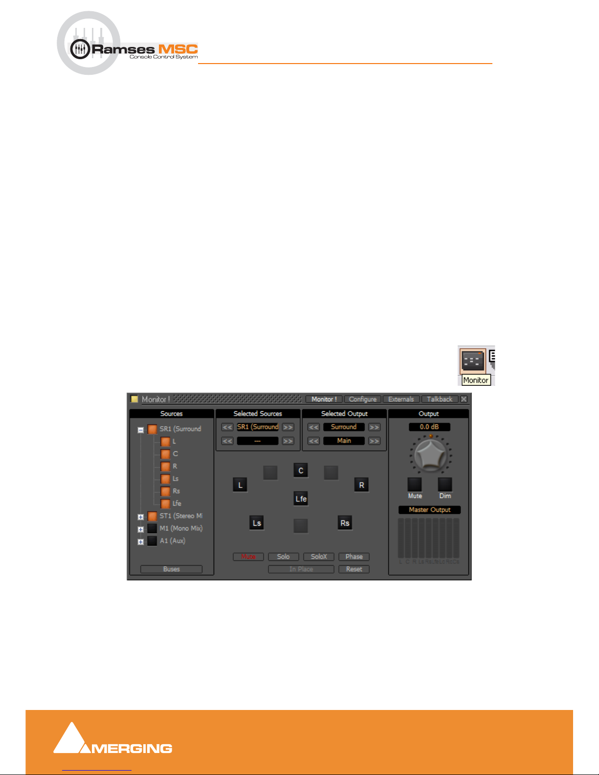
Monitor Setup in Pyramix
The Pyramix Monitor (Version 6 or higher with MassCore option) setup is system based (as opposed to
stored with individual Projects). A monitor setup is saved when the Pyramix application is closed. All the
Projects you open with your
Ramses MSC will have the Monitor section currently stored in Pyramix.
However, Talkback assignments and Mix Buses are saved with Pyramix Projects.
Before you can use the Monitor it must be enabled by clicking the button in the top-left corner of the window
so that it lights yellow.
By default the
Monitor window is hidden. It can be opened with View > Monitor or the icon in the
View
Toolbar.
Note: Please see: Pyramix Monitor Section on page 62 for full details.
Tips and tricks
Ramses makes available the speakers sets (orange buttons) set up in the Pyramix monitor section. They
are mapped in top to bottom order from the list in
Available Sets.
Monitor Main Monitor ! Window
Page 38

Monitor Panel
5 - 38
Ramses MSC reference guide
Monitor Panel : Meter Bridge Setup in Pyramix
Since the Ramses buttons are labeled surround, stereo & near you may wish to follow this convention
when naming speaker sets in the Pyramix Monitor.
External Sources in Pyramix
Note: Pyramix External Monitor Sources e.g. recorders, are set up in the Pyramix Monitor
Talkback in Pyramix
Note: Pyramix Talkback which provides the Ramses talkback functionality is set up in the
Pyramix Monitor
Meter Bridge Setup in Pyramix
The Meter Bridge is Project based in Pyramix 6. (This might change in 6.1). So please bear in mind that it
must be enabled in each project. (Pyramix Mixer Configure page, bottom-left)
Although you can set it up in the space you need or want it has been designed to fit 32 strips per row across
a 19” TFT screen.
Tip
If you enable the Meter Bridge in your Templates then it will be enabled by default in your Projects.
Note: Please see: Meter Bridge on page 80 for full details.
Page 39
Expert Panel
6 - 39
Ramses MSC reference guide
Expert Panel : Meter Bridge Setup in Pyramix
6 Expert Panel
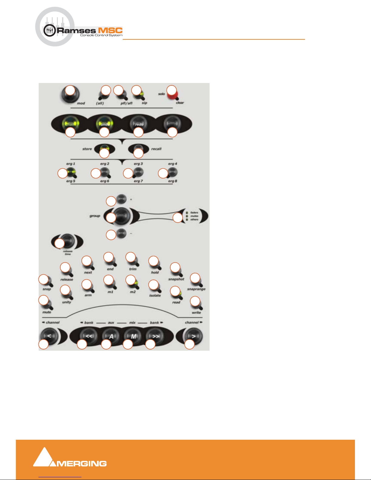
Expert panel Overview
1. mod button (modifier)
2. (all) button
3. pfl/afl - Solo Mode toggle PFL/AFL button
4. sip - Solo Mode - Solo In Place button
5. solo clear touch point
Ergonomic Spread Buttons
6. chair (ARC ONLY)
7. undo
8. redo
9. touch
10. store
11. recall
12. erg1 - erg8 Hotkeys 1-4 and 5-8 with mod
Grouping
13. + Add to Group button
14. group mode button
15. - Subtract from Group button
16. faders Target Indicator
mutes Target Indicator
others Target Indicator
Automation
17. release Time Knob
18. snap button - Release Mode
19. Auto release - Release Mode
20. to next - Release Mode
21. to end - Release Mode
22. trim Mode button
23. hold - Release Mode
24. snapshot - (Write Keyframe)
25. snaprange (Write Range Keyframe
26. mute button (ARC only)
27. unity button
28. arm Track button
29. m1 & m2 Memory 1&2 (Clipboard) buttons
30. isolate Mode button - Automation
31. read Mode button - Automation
32. write Mode button - Automation
Navigation
33. < channel Nudge 1 Channel to the Left
34. > channel Nudge 1 Channel to the Right
35. << bank Nudge 1 Bank to the left
36. >> bank Nudge 1 Bank to the Right
37. A - aux Show Aux Master buses
38. M - mix Show Mix master Buses
17
9
11
16
15
14
10
876
542 3
12
13
1
28
29
30
27
26
25
23
2221
20
19
18
24
12 12 12
29
31
32
33 35 37 38 36 34
Expert Panel
Page 40

Expert Panel
6 - 40
Ramses MSC reference guide
Expert Panel : Expert Panel Overview
Expert Panel Overview
This panel includes controls used to manipulate your work environment.
It includes the following blocks of controls:
Navigation Block : Controls navigation through channels and buses
Solo Block : Controls the behaviour of the Solo functions
Ergonomic Spread Block : Controls the selection of Channels into Slots
Grouping Block : Controls Grouping Functions
Automation Mode Block : Controls Automation modes
Strip Modifier / Automation Block :
Allows different modes of interaction
1 Modifier button - mod
Overview
The mod button acts like a Shift key in that it changes the function of other controls on the surface. It is
mainly used for the following purposes (while holding
mod):
• with the top encoder of an EQ changes the
Q factor
• Enables ergonomic spreads
5 - 8 to be recalled or stored
•with
isolate, read & write changes the global automation mode
• Enables mix buses to be summed in the monitoring section
mod button indicator
This indicator is illuminated whenever the Smart button is pressed.
2 All button
The all buttons, when pressed, are the equivalent of selecting all channels/strips of your mixer. To apply a
change everywhere, it can be seen as a modifier.
Both
all buttons operate identically.
For example:
Holding down the unity button and then pressing an all button will set all faders available in the current
project to Unity (0dB). This is not yet implemented with plugins, auxs or pans.
ALL button indicator
The all button indicator is illuminated whenever either all button is pressed.
Tips and Tricks
In the Ramses System > Configuration pages a timed value can be set which determines the length of
time that the
ALL remains active after it has been pressed. This avoids the need for multi-fingered virtuos-
ity in order to access multi-button functions.
3 pfl/afl button
Overview
The pfl / afl button toggles the solo mode between Pre-Fade-Listen and After Fade Listen i.e. normal Solo.
Page 41

Expert Panel
6 - 41
Ramses MSC reference guide
Expert Panel : Expert Panel Overview
PFL/AFL button indicator
The pfl / afl button indicator is lit whenever the console is in Pfl or Afl Solo Mode
4 SIP button
Overview
The SIP button toggles the solo function between Solo-In-Place and normal.
SIP button indicator
The SIP button indicator is lit whenever the console is in SIP solo mode.
5 Solo Clear touch point
Overview
Touching the Solo Clear touch point (which is also the Solo Master indicator) clears any and all currently
active solos. It is functionally identical to the
Solo Clear touch point on the Lower Active Panel (SEE
PAGE)
Normal Operation
If any channel is solo-ed the Solo Master indicator will be lit. Now, when touched, all solos will be removed,
all channel Solo indicators extinguished, the
Solo Master indicator itself will be extinguished and the moni-
tors resume their normal monitoring mode.
Additional Functions
The Solo Clear touch point also acts as an escape style command for various different modes. When
touched while in
Grouping Mode, it exits Grouping Mode and reverts to the group states before Group
Mode was entered. Similarly in
Ergonomic Spreads Store Mode, when pressed the Store mode is
cleared.
Solo Master indicator
The Solo Master indicator is illuminated if any channel is solo-ed.
Note: This control has two functions. It's indicator functions as a Solo Master indicator,
while it's Touch Control functions as a Solo Clear.
Tips and Tricks
The Solo Clear touch point also acts as an 'escape' style command for various different modes. When
touched while in
Grouping Mode, it exits Grouping Mode and reverts to the group states before Group
Mode was entered. Similarly in Ergonomic Spreads
Store Mode, when pressed the Store mode is cleared.
6 Chair button - ONLY AVAILABLE WITH ARC OPTION
Overview
The Chair button toggles between Chair Mode and Wipe Mode. These two modes determine how channels are selected using when touching
Segments on the ARC™. These modes apply equally to any type
of signal paths the ARC™ is displaying using the Aux "
A" or Mix "M" Buttons.
Chair Mode
In Chair mode, when you touch a Segment of the ARC™, your finger becomes a central point, representing your chair, and the strip you are pointing to as well as those surrounding your finger are immediately
loaded into all available strip
Slots. The number of channels or segments being loaded into Channel Slots
is displayed by a 'window' of lit channel numbers on the ARC™.
Page 42

Expert Panel
6 - 42
Ramses MSC reference guide
Expert Panel : Expert Panel Overview
The size of the 'window' of faders selected around your finger, is determined by the number of physical
strips, or Slots, your console has, minus the number of strips currently in Hold (see page) Thus a 16 fader
console with 6 faders in hold, will display a 'window' 10 segments wide.
A slot with its
Hold button on will not have its channel updated by this process.
A Slot whose fader is currently being touched will have a channel assigned to it as if it were a normal 'unheld' channel, but this slot will not be re-assigned until it's fader is released.
When the 'window' consists of an even number of ARC™ Segments, the centre point of the window around
your finger will be the left member of the middle pair of Segments. For example, if the window is 10 Segments wide, there will be the four strips to the left of your finger, and five to the right, with the fifth window
being the one your finger is on.
A further example:
In a 16 fader console, with slots 4,7,9 and 13 held (with their corresponding channel numbers) touching the
ARC™ in chair mode at Segment 35 would result in a window 12 Segments wide and will load channels
into slots resulting in the following order of channels: 30,31,32,4,33,34,7,35,9,36,37,38,13,39,40,41.
Note: When you touch segments near either end of the ARC™ the 'window' does not slide
off the end but rather remains at full width and ceases moving.
Wipe Mode
Wipe mode allows the selection of non-sequential arrangements of channels. Here, touching the ARC
Segments (in any order) on the ARC Selector Strip fills in individual channels sequentially from the left most
available physical channel through to the right most. The process starts again, and the left most available
physical channel slot is again filled, when the Timmometer decays.
Chair button indicator
The Chair button indicator is lit when the console is in Chair mode. When the console is in Wipe mode,
the indicator is extinguished.
Please note that this button is inactive without the ARC option
7 Undo button
Pressing the Undo button reverts to the previous ergonomic spread (layout).
Undo button indicator
The Undo button indicator is lit whenever there is a possible state to apply Undo to.
8 Redo button
Pressing the Redo button re-asserts the ergonomic spread (layout) in use prior to hitting Undo.
Redo button indicator
The Redo button indicator is lit only whenever there is a Redo action available.
9 Touch button
Some physical controls on the Ramses Console are not touch-sensitive. The touch button allows you to
use these controls in
touch automation modes as if they were touch-sensitive.
If, under touch automation mode, a non touch-sensitive parameter is altered, it will send a touch message
to the engine, triggering the engines usual response to a control that has been 'touched'. Now the
Tou ch
Page 43

Expert Panel
6 - 43
Ramses MSC reference guide
Expert Panel : Expert Panel Overview
button will light and the parameter you just updated will remain in touch mode until you press the touch button. At this point the
Touc h button is no longer illuminated and the parameter you moved no longer sends
'touched' messages. You can move as many parameters as you like and the
touch button will continue to
send touch messages for all those parameters until it is pressed at which time touch is released for those
controls.
Arming non touch-sensitive controls
Should you want to put a non touch parameter into 'touch' without moving the parameter, press and hold
the
touch button and then move a non-touch control on the surface. This will end a touch message to the
engine - but while, the button is held down, the controls themselves are prevented from changing their values. This is similar to the way in which parameters are selected for copying via the
m 1-2 buttons (see
page).
Note: It is possible to touch parameters by holding down the touch button and then wiggling the control even if some controls are already in touch mode and the button is lit.
When releasing the button after such an action, the button remains lit and parameters
already in touch remain so. In this case, to release touch from all parameters, press the
Touch button.
The Faders, aux knobs and joystick are true touch-sensitive controls and send touch messages when they
are indeed touched.
10 Store button
Overview
An Ergonomic Spread is the layout of faders currently selected to the surface of the console. The Ergo-
nomic Spread Store
button allows the storage of the current Ergonomic Spread into one of the Ergo-
nomic Spread
buttons 1-8.
Note: Storing and Recalling an Ergonomic Spread is an entirely non-destructive process.
The only thing that updating, recalling or modifying an Ergonomic Spread affects is which
faders are currently selected to the slots in your console.
Normal Operation
Pressing the Store button lights the Store button indicator and enters Store Mode - until one of the four
Ergonomic Spread buttons on the Expert Panel is pressed, or using the mod button to access Ergonomic Spread 5-8
- at which point the current Ergonomic Spread is stored into button and Store Mode is
exited.
To escape from
Store mode without storing the spread - touch either Solo Clear touch point. This will
extinguishe the
Store button indicator and exits the mode.
A Store operation will store the state of slots, including
HELD Channels. HELD channels are, however not
updated by the corresponding
RECALL command - see below.
Store button indicator
The Ergonomic Spread Store button indicator is lit whenever the system is in Ergonomic Spread Store
mode
.
Tips and tricks
The Ergonomic Spread is stored in Templ a t es and is part of their recall (see page)
Page 44

Expert Panel
6 - 44
Ramses MSC reference guide
Expert Panel : Expert Panel Overview
11 Recall button
Overview
An Ergonomic Spread is the layout of faders currently selected to the surface of the console. The Ergo-
nomic Spread Recall
button allows the recall of an Ergonomic Spread from one of the Ergonomic
Spread buttons 1-4
or with the mod button Ergonomic Spreads 5-8
Note: Storing and Recalling an Ergonomic Spread is an entirely non-destructive process.
The only thing that updating, recalling or modifying an Ergonomic Spread affects is whichfaders are currently selected to the slots in your console.
Normal Operation
Pressing the Recall button starts the Recall button indicator flashing and lights the Ergonomic Spread
buttons 1-4
that contain a saved Ergonomic Spread. Pressing the mod button will do the same for Ergo-
nomic spread 5-8
.
This state remains active until an
Ergonomic Spread 1-4 button (or 5-8 with mod button) is pressed that
contains a stored
Ergonomic Spread - at which point the Ergonomic Spread stored in that Segment or
button is recalled and applied to the console. Now both the
Recall button indicator and UPO indicators are
extinguished and
Recall Mode is exited. Held Channels are not updated by this process and retain their
original channels.
Note: Whilst in Recall mode an Ergonomic Spread 1-4 button that does NOT contain an
Ergonomic Spread - does nothing. Recall Mode remains active.
Escape from Recall mode
At any time you can escape from Recall mode without having selected any new Ergonomic Spread by
touching either of the
Solo Clear touch points.
Recall button indicator
The Ergonomic Spread Store button indicator will be lit whenever the system is in Ergonomic Spread
Recall mode
.
Tips and tricks
• It is not necessary to press recall each time, just touching the desired Ergonomic Spread number
is sufficient to
recall it.
Note: The button will only light if there is a previously stored Ergonomic Spread.
12 Ergonomic Spread buttons 1 - 4 / 5 - 8
The Ergonomic Spread buttons 1-4/5-8 are storage locations for Ergonomic Spreads.
Ergonomic Spread buttons 1-4 indicators
An Ergonomic Spread button indicator is lit when it has an Ergonomic Spread Stored. These stored
Ergonomic Spreads are saved with each console
Template or in the Pyramix project (see page)
13 Add to Group button (+)
In Grouping Mode
When in Grouping mode, pressing the + button initiates 'add to existing group' mode. See the Group
button (page) for more details.
Expert Grouping Mode
Page 45

Expert Panel
6 - 45
Ramses MSC reference guide
Expert Panel : Expert Panel Overview
In Grouping mode, the + button, when pressed together with the - button, initiates Expert Grouping Mode.
In this case both
+ and - indicators are lit and addition as well as subtraction from the currently selected
group is possible. See the
Expert Grouping Mode description in the Grouping button page for more
details.
+ button indicator
The + button indicator is lit under two conditions:
• Whenever the console is in '
Add to Group' Mode. This is initiated by hitting the + button after hit-
ting the
Group button.
• Whenever the console is in
Expert Grouping Mode. This is initiated by holding down both the -
button and + button at the same time whilst in Grouping mode.
See the
Group button description below for more details on these modes.
14 Group button
Overview
Pressing the Group button opens and closes the grouping process. Its indicator is lit whilst the mode is
active.
Note: As of today, you can group faders, mutes, solos and EQ. In a future version you
will be able to group pans, Dynamics and all other plugins. Note that only faders are
"linked" today and all other multi-value parameters have no offset in their grouping, so it
will behave as a "hard link" This will be change in future release.
Fader Grouping
Adding Faders to or creating a new Fader group
• Press the
Group button. (Group button indicator lights, the target indicator corresponding to the
last selected target lights -
Faders, Mutes or Others)
• Now touch any
Fader. (If not already, Faders are now selected as the grouping target and the Fad-
ers
indicator is lit in the Meter Bridge).
If the first Fader touched is
not already in a group, a new group is created consisting of (initially) just this
Fader and
Group + Mode is automatically initiated (+ indicator is Lit). Now any Fader or Segment touched
will be added to the group. The group members are updated in real time to indicate all members of the current group.
Note: Once you've created a new group and are adding Faders, touching a Fader that
belongs to another group will remove the Fader from its previous group and add it to the
group currently being modified.
If the first Fader touched is already part of an existing group - that group is now selected. All Meter Bridge
indicators for this group remain on. No Group modification is allowed now until either the
Group or Group
+
button is pressed. Any other group can be selected by touching one of it's members. Meter Bridge indica-
tors update to show this group's members.
Removing Faders from a Fader Group
•Pressing the Group - button whilst in Group mode will maintain the selection of the current Group,
change from the
+ to the - indicator being illuminated and now allow the subtraction of any Fader/
segment touched from the currently selected Group.
Escape from the Group
Page 46

Expert Panel
6 - 46
Ramses MSC reference guide
Expert Panel : Expert Panel Overview
• Whilst in any Grouping mode pressing the Group button exits the Grouping mode
• Touching either Solo Clear touch point (Please see: 5 Solo Clear touch point on page 41)
escapes from
Grouping mode and discards any changes made since the mode was initiated.
Mute Grouping
Adding Mutes to or creating a new Mute group
• Press the Group button. (Group button indicator lights on Meter Bridge, the target indicator corre-
sponding to the last selected target lights (
Faders, Mutes or Others)
• Now touch any
Mute
If the first Mute touched is not already in a Group, a new Group is created consisting of (initially) just this
Mute (only this Mute's Meter bridge indicator is now lit) and Group + Mode is automatically initiated (+ indi-
cator is Lit). Now any
Mute or Segment touched will be added to the Group. Meter Bridge indicators are
updated in real time to indicate all members of the current Group.
Note: Once you've created a new group and are adding Mutes, touching a Mute that
belongs to another Group will remove the Mute from its previous Group and add it to the
Group currently being modified.
If the first Mute touched is already part of an existing Group - that Group is now selected. No Group mod-
ification is allowed now until either the
Group - or Group + button is pressed. Any other Group can be
selected by touching one of it's members - Meter Bridge indicators update to show this Group's members.
Removing Mutes from a Mute Group
Pressing the Group - button whilst in Group mode will maintain the selection of the current Group, change
from the
+ to the - indicator being lit and now allow the subtraction of any Mute/Segment touched from the
currently selected
Group. If no Group is selected on entering Group Minus Mode, the first Mute touched
selects the
Group to be subtracted from.
Escape from the Group mode
Pressing the Group button at any time exits the Grouping mode.
Touching the
Solo Clear touch point escapes from Grouping mode and discards any changes made since
the mode was initiated.
Additional Notes
It is possible to specify multiple Groups without ever leaving Group mode. For example:
•Press
Group (Group buttons indicator is lit).
•Any
Faders now touched will become grouped together
• Press any
Mute button and the grouping function now changes to Mute groups (Previous Group’s
Meter bridge indicator's are extinguished and are replaced with Meter Bridge indicators for the new
Groups mutes).
• Press any
mutes desired to create new mute Group.
• Touch a
Fader now and the grouping function switches back to Fader grouping (Previous Group’s
Meter bridge indicators are extinguished and are replaced with Meter Bridge indicator for the new
Groups Faders).
Note: It is possible to define multiple Fader groups in this way by pressing any mute but-
ton between Groups of Faders. Pressing a single mute button and then another Fader will
not create any Group for the mute.
Page 47

Expert Panel
6 - 47
Ramses MSC reference guide
Expert Panel : Expert Panel Overview
Temporary Adjustment mode
Faders
In order to perform Fader (or other controls that have been grouped) moves without invoking group
laws, simply press and hold the - button down (indicator illuminates under your finger), wiggle a
Fader, release Fader, then release the - button. When the - button is released, the Fader returns to
position previously held in relation to the group and normal grouping laws are re-asserted. This
allows quick adjustments of Faders independent of the group relationship.
Mutes
Mutes
behave similarly in this mode with the exception of their behaviour after the - button is
released. Pressing and holding down the
- button and hitting a mute will toggle that channel's mute
state independently of the
mute group. Releasing the - button does not revoke the mutes modified
whilst in the temporary '
escape from group' mode but leaves them in the state they were changed
to.
Normal Group behaviour is asserted on the next Group change using the principle of positive assertion: If
the first
mute pressed after leaving temp adjustment mode changes from muted to un-muted, all other
Group members (regardless of their state) become un-muted. If the Mute pressed changes from un-muted
to muted, all other members of the Group become muted.
Expert Temporary Adjustment Mode
Whether the adjusted faders snap back to their original positions or all the untouched group members jump
to the positions dictated by the moved fader is now determined by which is released first: the
- button or the
Fader.
- Button First
Release the - button while holding a Fader and all the grouped faders will now jump to reassert the group
relationship but according to the fader level you are holding.
Fader First
Release the Fader and now release the - button and all the faders jump back to the positions they were in
before you hit the minus key.
mod - modifier Change
Whilst in Group mode, pressing the mod button toggles through the three different Grouping targets: Fad-
ers
, Mutes and Others. With each press each mode’s respective indicators are lit and the Meter Bridge
indicators of all members of all groups of this type are displayed.
Expert Grouping Mode
Whilst in Grouping Mode, and having selected a Group, pressing both the + button and the - button at the
same time enters
Expert grouping mode. In this mode both Addition and Subtraction from the group is
possible. This mode can be applied to all grouping targets and all other normal grouping rules apply.
Group button indicator
The Group button indicator is lit whenever the console is in any grouping mode. This is initiated by hitting
the
Group button.
Tips and tricks
•To Group two Faders together (providing they are not already in a Group), simply hold the two fad-
ers you wish to Group - and tap the
group button twice. The Faders are now grouped
Page 48

Expert Panel
6 - 48
Ramses MSC reference guide
Expert Panel : Expert Panel Overview
• To recall a Group and all its faders onto the surface, press recall, then group and then touch a
Fader being part of the desired Group, all the Faders belonging to this Group are now in front of
you.
15 Subtract from Group button (-)
In Grouping Mode
When in Grouping mode, pressing the - button initiates a 'remove from an existing group' mode. (Please
see:
14 Group button on page 45) for more details.
Expert Grouping Mode
In Grouping mode, the - button, when pressed together with the + button, initiates Expert Grouping
Mode
. In this case both + and - indicators are lit and addition as well as subtraction from the currently
selected group is possible. Please see
Expert Grouping Mode on page 47 for more details.
Temporary Adjustment Mode
The - button can also be used to initiate a 'temporary adjustment' mode. This mode allows controls to be
moved independent of group laws. It is initiated by holding down the
- button whilst not in Group mode.
Please see:
Temporary Adjustment mode on page 47 for more details.
- button indicator
The - button indicator is lit under three conditions:
• Whenever the console is in '
Remove From Group' Mode. This is initiated by hitting the - button
after hitting the
Group button.
• Whenever the console is in
Expert Grouping Mode. This is initiated by holding down both the -
button and + button at the same time whilst in Grouping mode.
• Whenever the
- button is held down whilst not in Grouping mode. This temporarily suspends
grouping laws allowing control of elements such as Faders or Mutes, independent of group control.
Please see item
14 Group button on page 45 for more details on these modes.
16 Faders, Mute & Other indicator
The Faders indicator is illuminated whenever the grouping mode is active and Faders have been selected
as the
grouping target.
See item
14 Group button on page 45 for more details of the Group modes.
The Mutes indicator is illuminated whenever the grouping mode is active and Mutes have been selected as
the grouping targets.
Please see item
14 Group button on page 45 for more details on these Group modes.
The
Others indicator is illuminated whenever the grouping mode is active and refers to Others.
After entering
group mode, if a control such as an EQ or AUX is touched, the target of the grouping func-
tion changes to that control. The indicator will now illuminate and remain lit until a Fader or Mute is touched
to specify an alternate grouping target, or
group mode is exited, either through pressing group again, or
Solo Clear to escape. It also can be anything on the Active screen.
17 Release time knob
Fader release time controls glide back when a Fader is released during automation.
Page 49

Expert Panel
6 - 49
Ramses MSC reference guide
Expert Panel : Expert Panel Overview
This is a rotary control (non-automated) that determines the speed at which a fader glides back to it's previously automated position after having been released (when in
release mode). When set to low (knob is
turned to the left) a Fader will take
0ms to return to its automated position after being released (the same
as
snap for all practical purposes). When turned to the right, it will take 10 seconds (10,000ms) to return to
its previously automated value after being released.
18 snap button
Invokes the Pyramix automation Snap release mode. The current value snaps back instantly to the value
written in the previous pass when the control is released.
The button lights when the mode is engaged. Please see the Pyramix V6 User Manual for more details.
19 release button
Invokes the Pyramix automation Auto-release mode. The current value morphs to the value written in the
previous pass when the control is released at a rate determined by the
release time knob.
The button lights when the mode is engaged. Please see the Pyramix V6 User Manual for more details.
20 next button
Invokes the Pyramix automation Write to Next mode. Writes automation until the current value matches
automation data written in the previous pass then it releases automation into
read.
The button lights when the mode is engaged. Please see the Pyramix V6 User Manual for more details.
21 end button
Invokes the Pyramix automation Write to End mode. The button lights when the mode is engaged. Please
see the Pyramix V6 User Manual for further details.
Note: At any time while writing automation you can set another release mode providing
Stop has not been pressed.
22 trim button
Invokes the Pyramix automation Tri m mode. The button lights when the mode is engaged. Trim mode
operates an a “Touch” basis. So long as you are touching the desired fader (or other encoder) trim mode
remains engaged. As soon as the fader is released the current release mode is activated. Please see the
Pyramix V6 User Manual for details.
Note: The orange TRIM LED adjacent to the fader is lit when Trim is active.
23 hold button
The encoder currently touched will be held until released The button lights when pressed.
Note: The purple HOLD LED adjacent to the fader is lit when Hold is active.
24 snapshot
Produces an automation snapshot (keyframe) of all touched encoders or, if inject is touched, for the
whole strip(s) of the current values at the Play cursor position.
Page 50
Expert Panel
6 - 50
Ramses MSC reference guide
Expert Panel : Expert Panel Overview
25 snap range
This is similar to the snapshot function except that it operates over a range determined by a Region
Selection
or In and Out Markers within the Pyramix application. Please see the Pyramix V6 User Manual
for details.
In the future (Pyramix V6.1) it will be possible to set these markers from within the Transport and Automation Active Screen.
26 Mute
Works as a normal mute button (used with inject) but is especially useful as modifier button
when used in conjunction with the optional ARC. The mute button indicator is lit whenever the
button is pressed.
Press and hold the Mute Modifier button while wiping the ARC either mutes or un-mutes those channels
using the following rules.
27 unity button
Press and hold unity and wipe over inject button. This will restore your faders to unity gain. You can do
the same with EQ's and other Ramses parameters.
Tips and Tricks
• Press and hold unity then press ALL restores the entire console (faders) to unity.
28 arm button
Hold arm and wipe over inject button. This will track arm your edit tracks (red indicator at the bottom of the
channel Vu meter and red outline in the Meter bridge) .
Note: Tracks can only be armed when they have an input connected to them.
Tips and Tricks
• If you press and hold arm then press ALL then all available tracks with inputs will track arm or dis-
arm.
mute with ARC
Touching an ARC Segment with mute held down not only changes the mute
state of that strip but also loads this change of state into memory and applies it to
all other Segments touched while the button is held down.
E.g. If the first segment touched is muted, this Segment will be un-muted and, if
you continue to wipe along the ARC all muted channels touched will be un-muted
whilst strips already un-muted are unchanged.
If the first Segment touched is un-muted, this Segment will become muted and all
subsequent Segments touched will either become muted, or if already so, remain
muted.
I.e. The first strip you touch determines whether you're modifying things to turn
ON or to turn OFF.
Page 51

Expert Panel
6 - 51
Ramses MSC reference guide
Expert Panel : Expert Panel Overview
29 m1 & m2 buttons
These are two "clipboard" memories. E.g. if there is a EQ curve that you wish to copy to another channel.
hold
m1 and press the EQ button on the desired strip. Then press and hold m1 and inject it into the
desired destination channel(s).
Tip and tricks
• Any type of value can be stored in these memories. While pressing and holding m1 you can move a
fader or any type of rotary control and, so long as you don't release the
m1 button, all those param-
eters will be stored in
m1.
• In the future the
library button above the Active Screen will offer many more memories.
30 isolate button
Automation
Holding down the Automation isolate button and then injecting any fader will change the state of the
selected strip to automation
Isolate Mode (or just the section(s), EQ, Dynamics, AUX etc. if you touch
them in the
Active Screen).
Strips selected using this mode remain in Automation Isolate mode until another mode is selected for them.
While the
isolate button is held down, the Meter Bridge indicators display all channels currently in Isolate
if automation feedback is activated in the Meter Bridge configuration.
Please see: Automation Fader
Mode on page 85
Isolate button indicator
The Automation Isolate indicator is illuminated when the Isolate button is pressed.
31 read button
Automation
Holding down the Automation read button and then injecting any fader will change the state of the selected
strip to automation
read Mode (or just the section(s), EQ, Dynamics, AUX etc. if you touch them in the
Active Screen).
Strips selected using this mode remain in Automation Read mode until another mode is selected for them.
While the
read button is held down, the Meter Bridge indicators display all channels currently in isolate if
automation feedback is activated in the Meter Bridge configuration.
Please see: Automation Fader Mode
on page 85
Read button indicator
The Automation Read button indicator is illuminated when the Read button is pressed.
32 write button
Automation
Holding down the Automation read button and then injecting any fader will change the state of the selected
strip to automation
write Mode (or just the section(s), EQ, Dynamics, AUX etc. if you touch them in the
Active Screen).
Strips selected using this mode remain in Automation Read mode until another mode is selected for them.
Page 52

Expert Panel
6 - 52
Ramses MSC reference guide
Expert Panel : Expert Panel Overview
While the read button is held down, the Meter Bridge indicators display all channels currently in write if
automation feedback is activated in the Meter Bridge configuration.
Please see: Automation Fader Mode
on page 85
Read button indicator
The Automation Read button indicator is illuminated when the Read button is pressed.
Page 53

Expert Panel
6 - 53
Ramses MSC reference guide
Expert Panel : Expert Panel Overview
31/32 Auto Write
Automation
Holding down the Automation read and write buttons together and then injecting any fader will change the
state of the selected strip to automation
read Mode (or just the section(s), EQ, Dynamics, AUX etc. if you
touch them in the
Active Screen).
Strips selected using this mode remain in Automation
auto-write mode until another mode is selected for
them.
While the
read & write buttons are held down, the Meter Bridge indicators display all channels currently in
auto -write by lighting both read and write indicators if automation feedback is activated in the Meter
Bridge configuration.
Please see: Automation Fader Mode on page 85
Auto Write buttons indicators
The Automation Read and Write button indicators are illuminated when the Read and Write buttons are
pressed.
Tips and tricks.
• You can have two automation status options, set in the Active Screen System > Configure menu.
One is single automation status per channel. I.e. Wherever you touch, the fader or inject will
change the automation status for the entire channel. The second option is per section. If you
change the automation status and e.g. touch the fader or the EQ button, the automation status only
changes for those elements touched. If you wish to change the status for the entire channel then
use
inject.
Note: The automation LED adjacent to the fader indicates the automation status for the
fader ONLY in the second mode.
Page 54
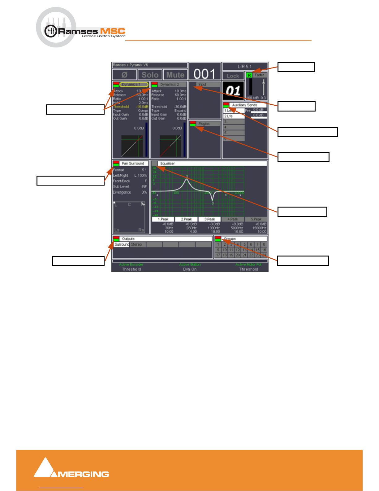
Expert Panel
6 - 54
Ramses MSC reference guide
Expert Panel : Expert Panel Overview
• Automation status feedback on active screen
33 & 34 channel nudge buttons
Navigation
Nudges the virtual strips to slots assignment one place to the left or right. Fader strips that are in Hold
mode remain unaffected.
35 & 36 bank nudge buttons
Navigation
Nudges the virtual strips to slots assignment one bank (8 fader strips) to the left or right. Fader strips that
are in
Hold mode remain unaffected.
37 Aux button
Navigation
Forces the aux bus masters onto physical fader strips. Fader strips that are in Hold mode remain unaffected.
auto-write dynamics
auto-write Pan Surround
auto-write Outputs
isolate Equaliser
read Fader
auto-write Groups
auto-write Aux Sends
auto-write Plugins
isolate Input
Automation indicators - Active Screen
Page 55

Expert Panel
6 - 55
Ramses MSC reference guide
Expert Panel : Expert Panel Overview
38 Mix button
Navigation
Forces the mix bus masters onto physical fader strips. Fader strips that are in Hold mode remain unaffected.
Page 56
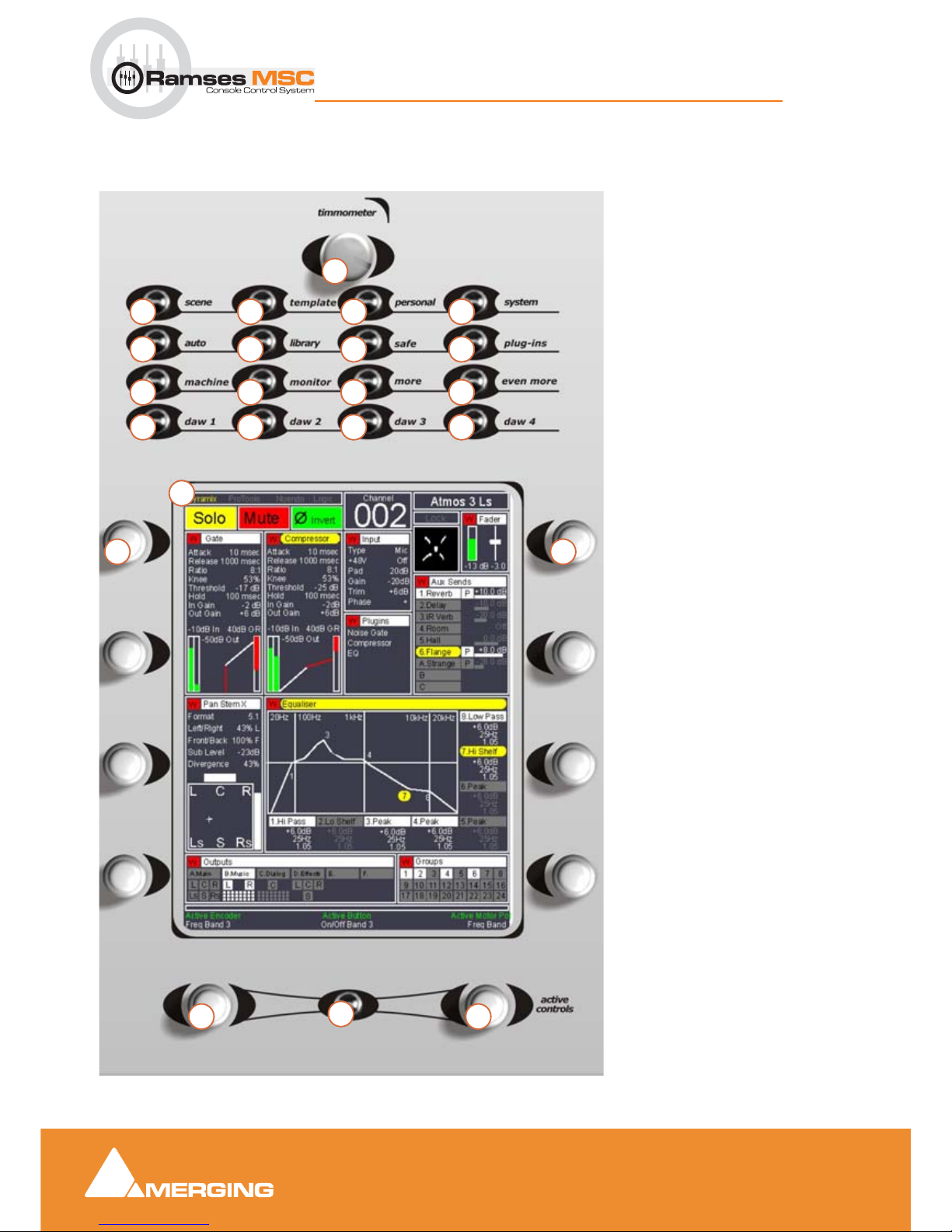
Upper Active Panel
7 - 56
Ramses MSC reference guide
Upper Active Panel : Expert Panel Overview
7 Upper Active Panel
Upper Active Panel
Overview
1. timmometer knob
2. scene button
3. template button
4. personal button
5. system button
6. auto button
7. library button
8. safe button
9. plug-ins button
10. machine button
11. monitor button
12. more button
13. even more button
14. daw 1 button
15. daw 2 button
16. daw 3 button
17. daw 4 button
18. Active Screen
19. dual-concentric encoders
20. active dual-concentric encoders
21. active button
9
11
14
10
876
542 3
13
1
12
171615
18
20
21
20
19 19
Upper Expert Panel
Page 57

Upper Active Panel
7 - 57
Ramses MSC reference guide
Upper Active Panel : Expert Panel Overview
1 timmometer knob
2 scene button
3 template button
4 personal button
5 system button
6 auto button
7 library button
8 safe button
9 plug-ins button
10 machine button
11 monitor button
12 more button
13 even more button
14 daw 1 button
15 daw 2 button
Page 58

Upper Active Panel
7 - 58
Ramses MSC reference guide
Upper Active Panel : Expert Panel Overview
16 daw 3 button
17 daw 4 button
18 Active Screen
19 dual-concentric encoders
20 active dual-concentric encoders
21 active button
Page 59
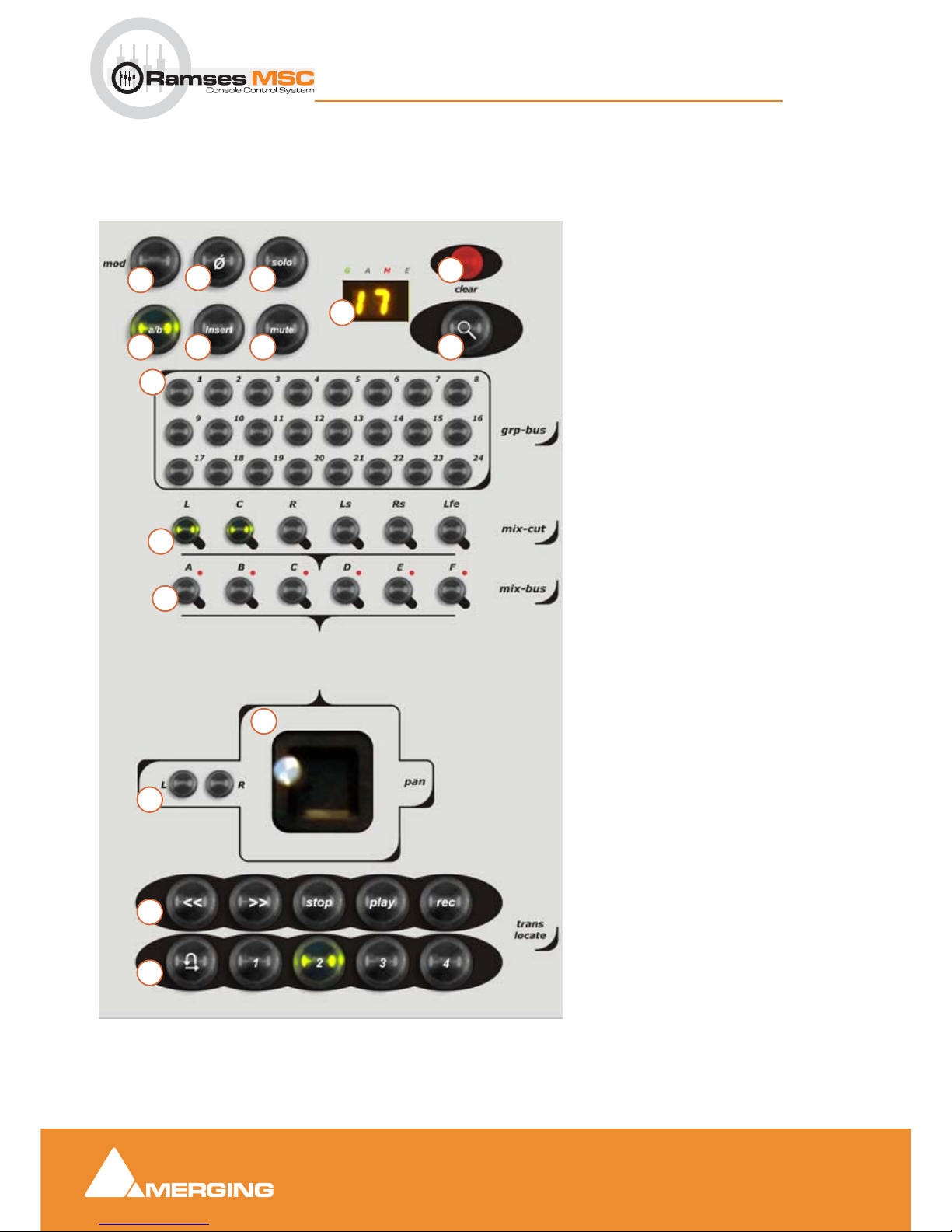
Lower Active Panel
8 - 59
Ramses MSC reference guide
Lower Active Panel : Expert Panel Overview
8 Lower Active Panel
Lower Active Panel
1. mod button
2. Ø phase reverse button
3. solo button
4. clear touch point
5. strip number display
6. a/b button
7. insert button
8. mute button
9. zoom button
10. grp - bus 1 - 24 select buttons
11. mix - cut surround channel buttons
12. mix - bus A - F select buttons
13. pan joystick panner
14. L & R panner select buttons
15. transport controls
16. locate buttons
10
12
15
11
876
5
4
2
3
14
1
13
16
9
Page 60

Lower Active Panel
8 - 60
Ramses MSC reference guide
Lower Active Panel : Expert Panel Overview
1 mod button
2 Ø phase reverse button
3 solo button
4 clear touch point
Overview
Touching the Solo Clear touch point (which is also the Solo Master indicator) clears any and all currently
active solos. It is functionally identical to the
Solo Clear touch point on the Expert Panel (Please see item
5 Solo Clear touch point on page 41)
Normal Operation
If any channel is solo-ed the Solo Master indicator will be lit. Now, when touched, all solos will be removed,
all channel Solo indicators extinguished, the
Solo Master indicator itself will be extinguished and the moni-
tors resume their normal monitoring mode.
Additional Functions
The Solo Clear touch point also acts as an escape style command for various different modes. When
touched while in
Grouping Mode, it exits Grouping Mode and reverts to the group states before Group
Mode was entered. Similarly in
Ergonomic Spreads Store Mode, when pressed the Store mode is
cleared.
Solo Master indicator
The Solo Master indicator is illuminated if any channel is solo-ed.
Note: This control has two functions. It's indicator functions as a Solo Master indicator,
while it's Touch Control functions as a Solo Clear.
Tips and Tricks
The Solo Clear touch point also acts as an 'escape' style command for various different modes. When
touched while in
Grouping Mode, it exits Grouping Mode and reverts to the group states before Group
Mode was entered. Similarly in Ergonomic Spreads
Store Mode, when pressed the Store mode is cleared.
5 strip number display
Displays the number of the strip currently being controlled by the Active Panels
6 a/b button
7 insert button
Bypasses the physical insert on the channel (future release)
8 mute button
Page 61
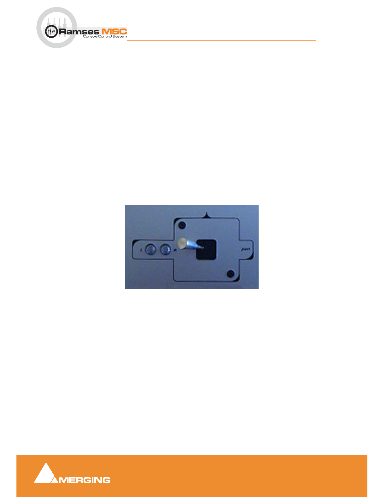
Lower Active Panel
8 - 61
Ramses MSC reference guide
Lower Active Panel : Expert Panel Overview
9 zoom button
10 grp - bus 1 - 24 select buttons
11 mix - cut surround channel buttons
See 12 below
12 mix - bus A - F select buttons
mix bus A - F buttons select a given bus’s stem. The LEDs above each Mix Bus button display the cur-
rently selected bus-stem. Once selected, you can use the
mix - cut buttons to determine which channels
of that stem you wish to send your signal to, simply by pressing the
mix - cut buttons. Lit buttons indicate
that the signal is being sent to this channel (the level is determined by the panner and fader). Unlit buttons
indicate that this signal is not being sent to this channel.
13 pan joystick panner
The joystick can be used to pan in surround space. I.e. LCR and FR or, by using the L & R buttons it can
be locked to horizontal or vertical axes. Panning can also be locked for the strip.
14 L & R panner select buttons
Pan Locking
The L - R buttons allow you to do the following depending on the combination:
•
L - locks the pan to horizontal LCR panning
•
R - locks the pan to vertical FR panning
•
L+R locks all panning for the strip
Indicators lit when mode selected.
15 transport controls
16 locate buttons
Page 62
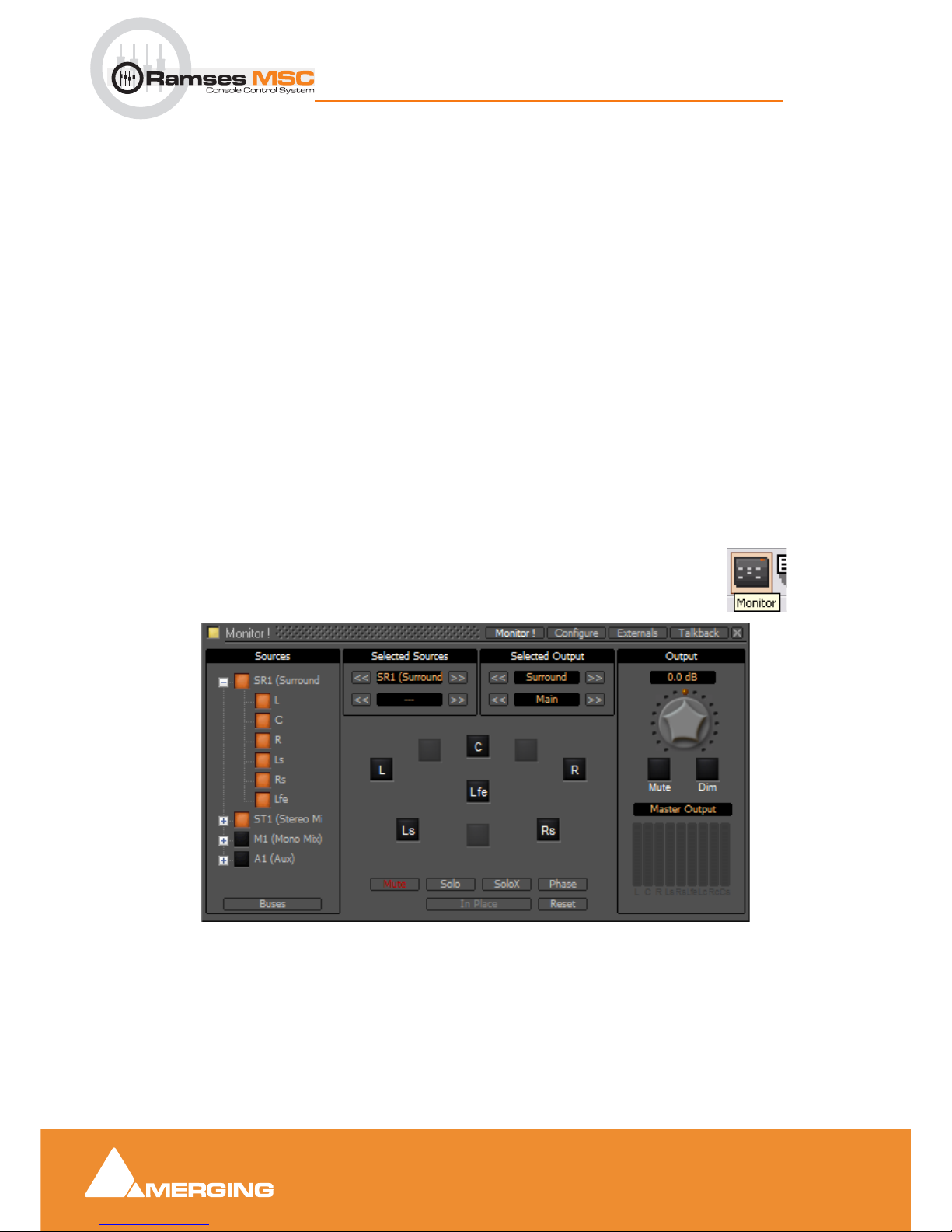
Pyramix Monitor Section
9 - 62
Ramses MSC reference guide
Pyramix Monitor Section : Monitor ! Window
9 Pyramix Monitor Section
Monitor ! Window
Scope
Pyramix has a dedicated Monitor section. This extremely powerful tool offers comprehensive monitoring
facilities including summing and downmixing for all supported formats. External Machine Inputs, comprehesive Talkback, Foldback and External Metering are also supported depending on your system specification.
The
Monitor presents monitor outputs of all buses present in the current Mixer as sources. It is also possi-
ble to configure external sources both for recorder returns and for talkback. Sources can be summed for
monitoring without affecting the Mixer bus outputs. This is useful, for example, when you need to listen to a
guide track while recording.
You do not have to use the
Monitor and disabling it will save DSP power but, with complex Mixers and
routing, the Monitor helps to keep things logical.
The monitor is also used to output the audio signal from the audition function of the Media Manager and
Libraries as an unformatted input. (I.e. Routed to LRC in a Surround 5.1 Speaker Set and to LR in a Stereo
one)
By default the
Monitor window is hidden. It can be opened with View > Monitor or the icon in the
View
Toolbar.
The Monitor has four pages: a Main
Monitor ! page in normal operation, a Configure page for setting up
and two further pages for configuring
Externals (machines) and Talkbac k.
Monitor Main Monitor ! Window
Page 63

Pyramix Monitor Section
9 - 63
Ramses MSC reference guide
Pyramix Monitor Section : Monitor ! page
Monitor ! page
The Monitor ! window is divided vertically into three sections.
Sources, left-hand section:
The button top-left of the title bar enables/disables the Monitor and lights yellow when enabled. This allows
DSP power to be saved when comprehensive monitoring control is not required. Below the
Enable Moni-
toring
button is a tree view of all busses used in the mixer. Clicking on the + and - boxes shows and hides
branches in the usual way. Click on any complete bus or any available stem or any bus/stem channel to
select it for monitoring. Selection is exclusive unless the
Ctrl key held is down. Then selection is cumula-
tive and clicking adds or subtracts Sources according to their current state.
Buses / Externals button
Note: At bottom left in the screenshot above the button labelled Buses indicates which
sources are available for activation. Clicking on this button toggles through Buses, Exter-
nals and Buses / Externals
Main, centre section:
Selected Sources
<< SR1 >>: Select previous/next Pyramix source. Only sources visible in the Sources section are
available. I.e. If the component channels of a bus or stem are collapsed this bus or stem is switched as a
unit when the component channels are visible in the
Sources section then clicking on the << or >> buttons
steps through each available channel in turn.
<< DA-88 >>: Select previous/next External Source. Only External Sources visible in the Sources sec-
tion are available.
Note: Clicking on any of the << or >> buttons cancels the selection made previously in the
Sources section.
Selected Output
<< Surround 5.1 >>: Select previous/next Speaker Set.
<< Main >>: Select the previous/next Downmix defined in the Configure page.
Main area
Speakers are inactive (grayed) if they are not connected in the Configure page.
The
Mode buttons at the bottom determine the function of the active Speaker buttons.
Mute: Clicking on a speaker mutes it. Selections are cumulative.
Solo: Clicking on a speaker solos it. Selections are cumulative.
SoloX: Solo eXclusive on the clicked speaker. Selections toggle.
Phase: Clicking on a speaker reverses its phase. Selections are cumulative. Useful for quick imaging
checks.
In Place Works in conjunction with Solo and SoloX. Toggles between In Place and Center.
Reset: Deselect all speakers.
Page 64
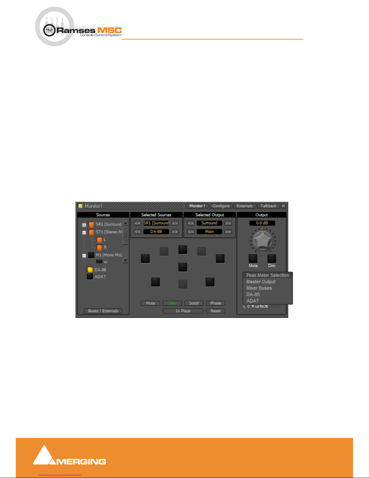
Pyramix Monitor Section
9 - 64
Ramses MSC reference guide
Pyramix Monitor Section : Monitor ! page
In Place/Center: In Solo and SoloX, toggles between In Place and Center. Center routes the soloed
channel(s) to the Center speaker or equally to the L/R speakers if no center speaker is present.
In Place
mode is the normal Solo, SoloX mode.
Output, right-hand area
Monitor Level box Displays the current output level. Output level can be entered numerically in the box
after clicking on it.
Volume Knob: sets all the output gains in a range from -144.5dB to +24dB. Double-click to set it to 0dB.
Note: Maximum permissible volume can be set in the Configure page.
Mute: button mute the outputs.
Dim: button reduces the output level by an amount set in the Configure page. Default value is -20dB.
Below these buttons is the
Peak Meter Selection: Indicator/Button. This indicates what the Peak Meter display below the button is
looking at. (The selection also affects External Metering if you are using it) Clicking on the button drops
down a list of sources that can be metered from a choice of
Master Output I.e.Monitor Output, Mixer
Buses
and any available Externals.
Speaker Sets
Speaker Sets are set-up in the Configure page.
A speaker set consists of:
A
Patch: This connects signals to the physical outputs of the board(s). The number of connection will
depend on the number of speakers you want to connect. Since the number of available live outputs
depends on the selected sampling rate, the patch will differ for 1Fs, 2 Fs, 4Fs and 8 Fs sampling rates.
Monitor Main Monitor ! Window Peak Meter Selection drop-down
Page 65
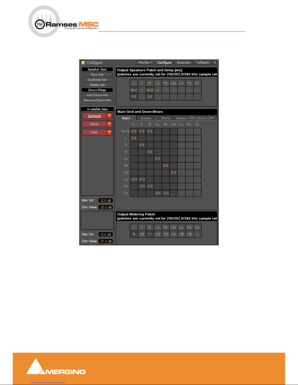
Pyramix Monitor Section
9 - 65
Ramses MSC reference guide
Pyramix Monitor Section : Monitor ! page
A Main grid: this matrix defines the relation between the Mixer’s busses output channel types and the
monitor’s output channel types (thus the monitor’s physical outputs). Typically, the main grid would show a
diagonal for the channel types patched:
A set of
Downmixes (max: 4) : A downmix is a an alternative grid which uses the same patch as the main
grid. In this page you can patch the outputs of you monitor, add/remove downmixes, and defines the corresponding grids in dB (only the channel types which are patched).
Monitor Configure Window
Page 66
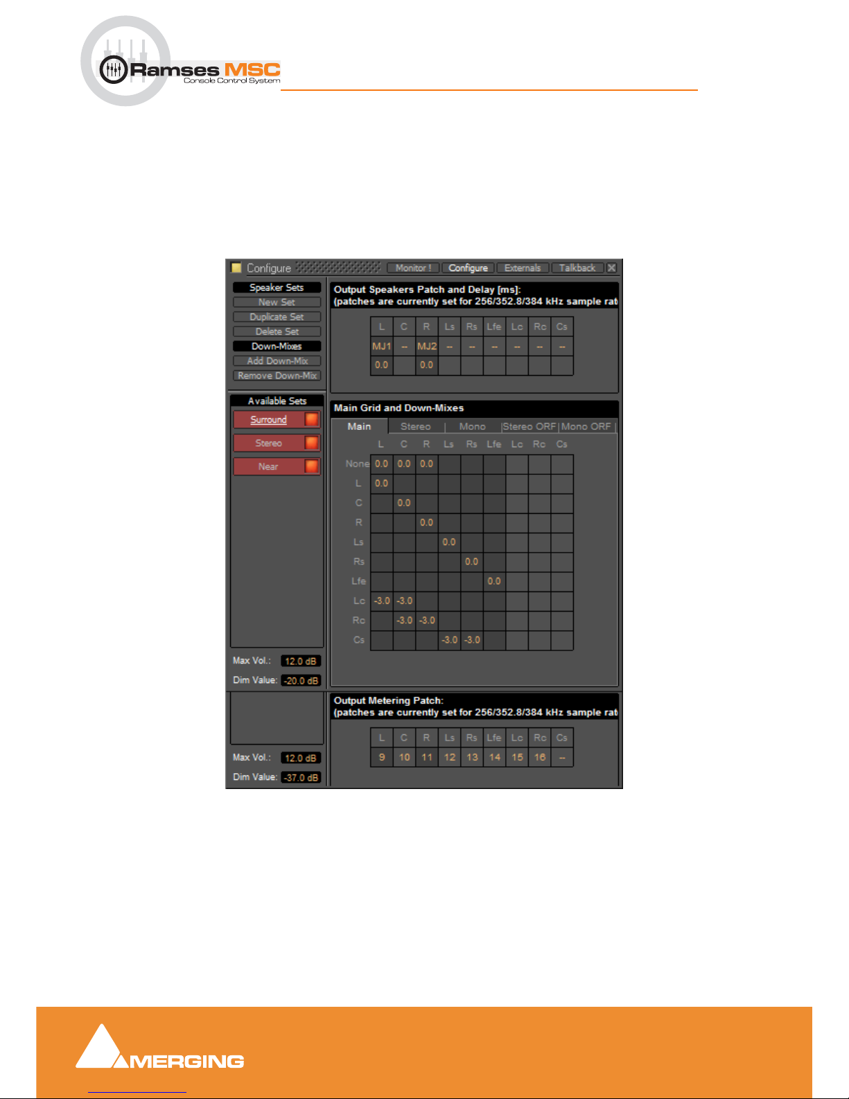
Pyramix Monitor Section
9 - 66
Ramses MSC reference guide
Pyramix Monitor Section : Configure page
Configure page
The Configure page enables multiple Speaker Sets, each with multiple down-mixes, to be created and
edited. Two factory Speaker Sets (
Stereo and Surround 5.1 labelled on a red background at the top of the
Speaker Sets list) are installed with Pyramix. Their Main channel to speaker Main Grid and Down-Mix
assignments cannot be changed, but their output Patches from speakers in the Monitor to physical outputs
can. They and each of their down-mixes can be enabled/disabled in order to determine which ones are visible in the main Monitor page.
The
Configure page is divided into four main areas; Speaker Sets and Down-Mixes, Available Sets,
Output Speakers Patch and Delay[ms], Main Grid and Down-Mixes and Output Metering Patch.
Available Sets
To select an existing Speaker Set in order to view or alter its settings, click on its title in the Available Sets
list. The label will become underlined and the Set’s parameters will appear in the grid. If the Set has DownMixes already defined there will be one or more tabs next to the
Main Tab in the Main Grid and Down-
Mixes
area.
Monitor Configure Window
Page 67
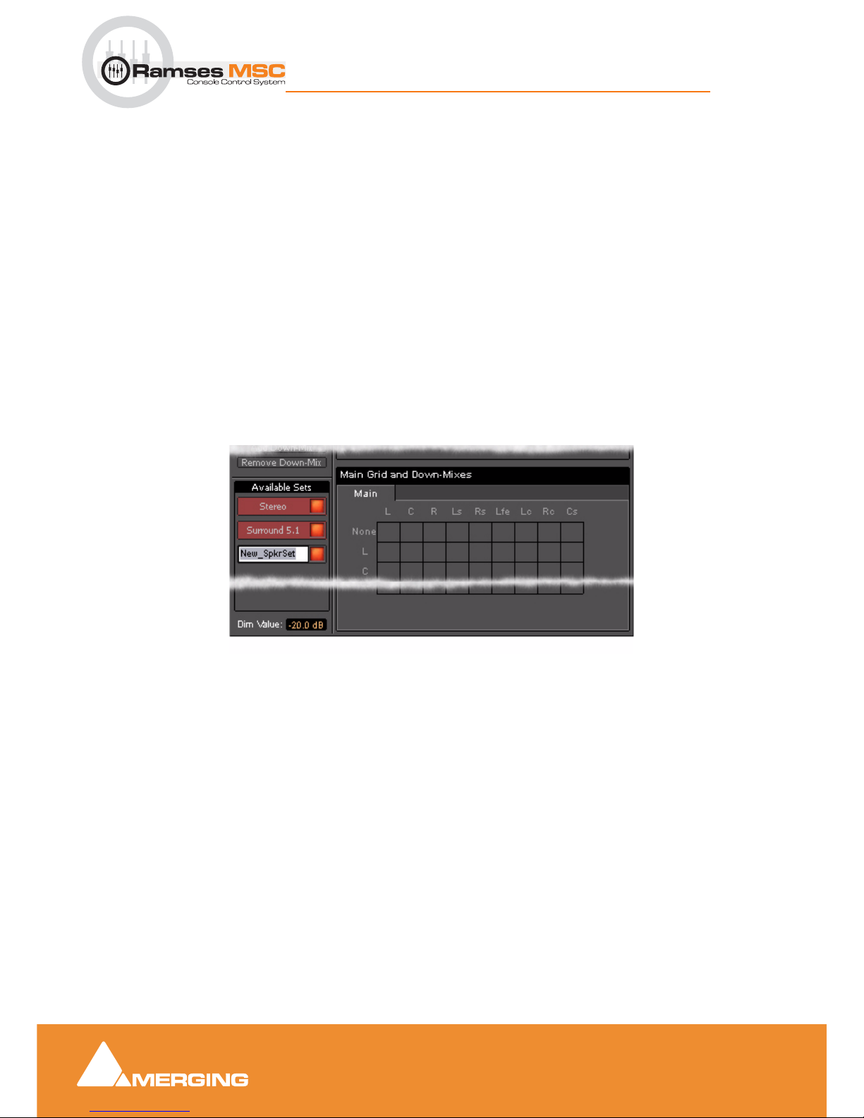
Pyramix Monitor Section
9 - 67
Ramses MSC reference guide
Pyramix Monitor Section : Configure page
Two sets, Stereo and Surround 5.1 are factory defined and cannot be altered. New Sets and Down-Mixes
can be
Created, Duplicated and Deleted using the Command buttons.
Max Vol
To set the maximum volume attainable click on the value box to highlight it and type the desired value then
hit
Enter or click elsewhere on the window to save the change.
Dim Value
To change the Dim Level, click on the value box to highlight it and type the desired attenuation value then
hit
Enter or click elsewhere on the window to save the change.
Note: Only negative values are accepted. Positive values revert to 0dB. I.e. Type “-15”
Commands
Speaker Sets
New Set
Clicking on New Set creates a new Speaker Set with a blank matrix Grid and adds a new entry to the Avail-
able Sets
list with the label highlighted ready for text entry:
Type a suitable name and click on a blank area or hit
ENTER to accept the name.
Duplicate Set
Creates a new Speaker Set with a the same matrix Grid settings and Down-Mixes and settings as the set
currently selected (underlined) and displayed in the grid. The new label is highlighted ready for text entry.
Delete Set
Deletes the currently selected (underlined) Speaker Set.
Down-Mixes
Add Down-Mix
Creates a new Down-Mix associated with the currently selected Speaker Set with a new tab in the Main
Grid
and Down-Mixes section.
Remove Down-Mix
Deletes the current Down-Mix
Monitor Configure New Speaker Set
Page 68
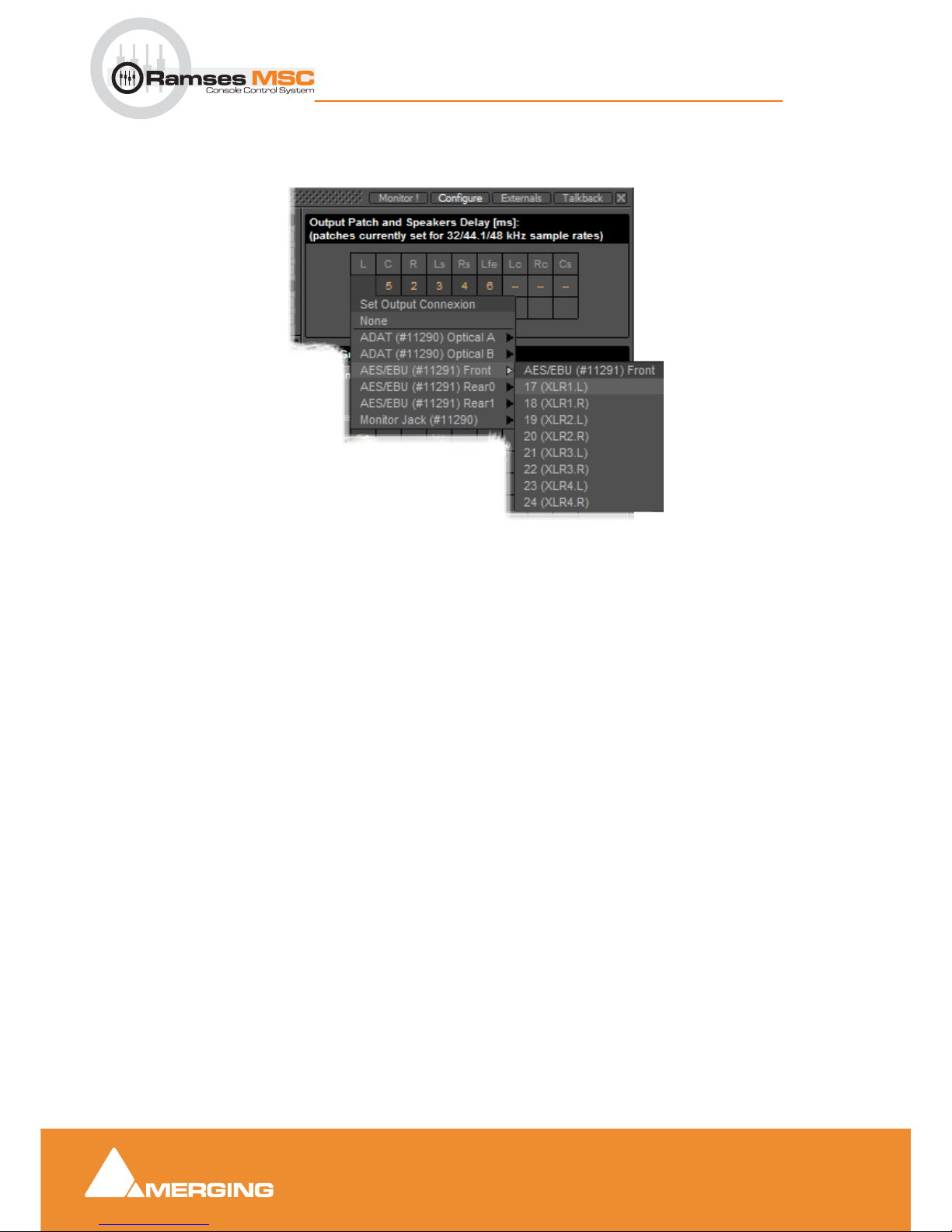
Pyramix Monitor Section
9 - 68
Ramses MSC reference guide
Pyramix Monitor Section : Configure page
Output Patch:
This is where the Monitor’s Speaker Set outputs are patched to physical outputs.
Clicking on a cell pops up the
Set Output Connection menu with all available physical outputs grouped by
their connectors. The sub-menus list the group and the individual channels. Select an individual channel to
connect it or select the group, e.g.
AES/EBU (#11291) Front to connect the whole group in ascending
order from the cell clicked on.
Note: Each Speaker Set has its own Output Patch associated with it. This is useful where
different speakers are used for different formats. If there is only one set of speakers patch
all Speaker Sets to the same physical outputs.
Double Assignment
When an output of the Mixer and an output of the Monitor are connected to the same physical output then
these are summed and the Mixer displays the connection in orange as a warning.
Speaker Delays
Delay can be set per Speaker by clicking in the box below the Output Connection and typing in a value.
Speaker delays are typically used to compensate for the physical positioning of the loudspeakers for example where the Left Centre and Right speakers are placed in a straight line, the Centre speaker will be
nearer to the listening position and should be delayed accordingly.
Saving Speaker Sets
Mixer to Monitor connection status is saved in the project.
The Speaker Set settings are saved when you leave the page to go back to the
Monitor ! page; otherwise,
modifications are not saved.
Monitor Configure Output Patch
Page 69
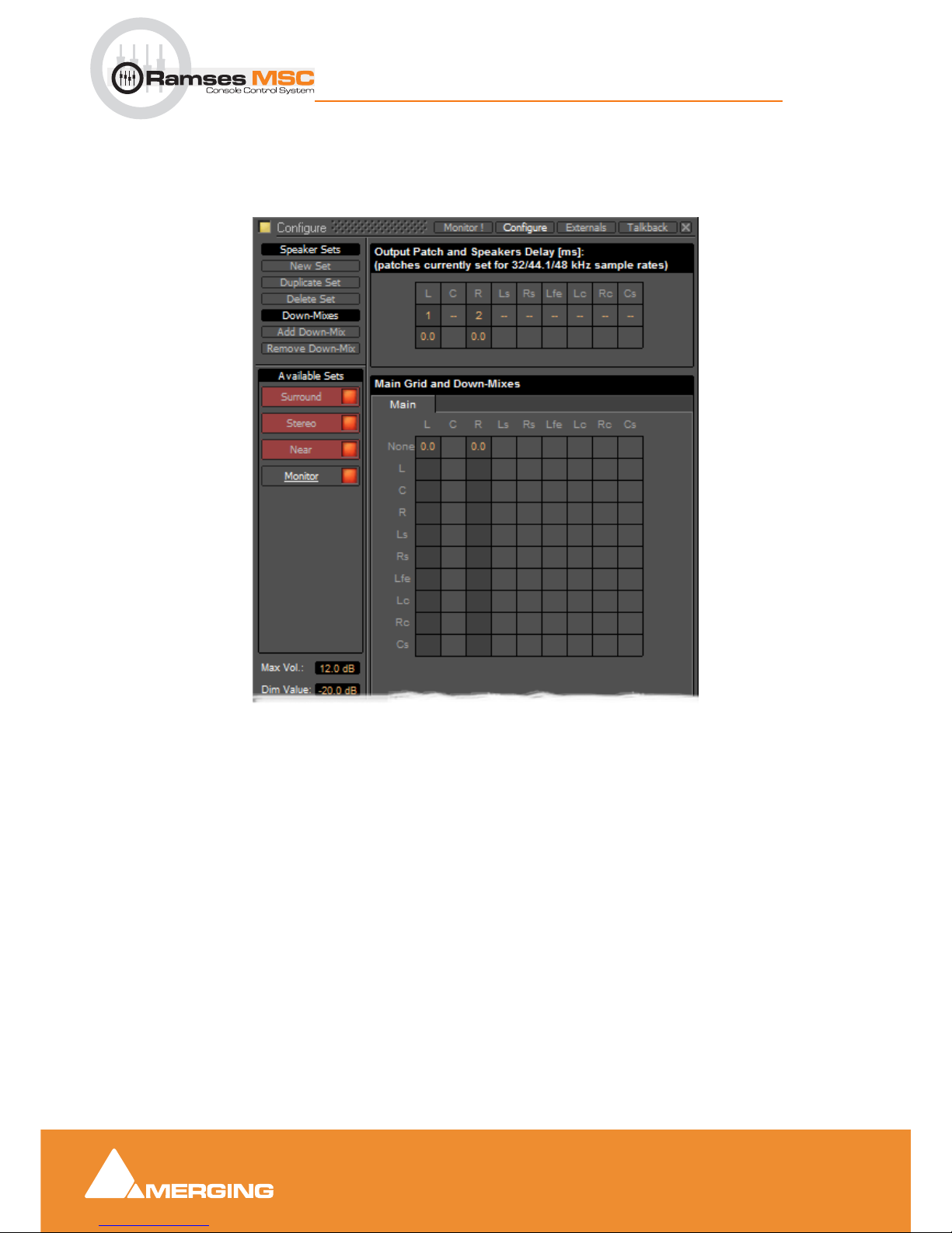
Pyramix Monitor Section
9 - 69
Ramses MSC reference guide
Pyramix Monitor Section : Media Manager Monitoring
Media Manager Monitoring
Note: In order to be able to audition cues in the Media Manager the L and R None entries
in the Main Grid matrix must be set to a value, e.g. 0.0
Monitor Configure Media Manager
Page 70
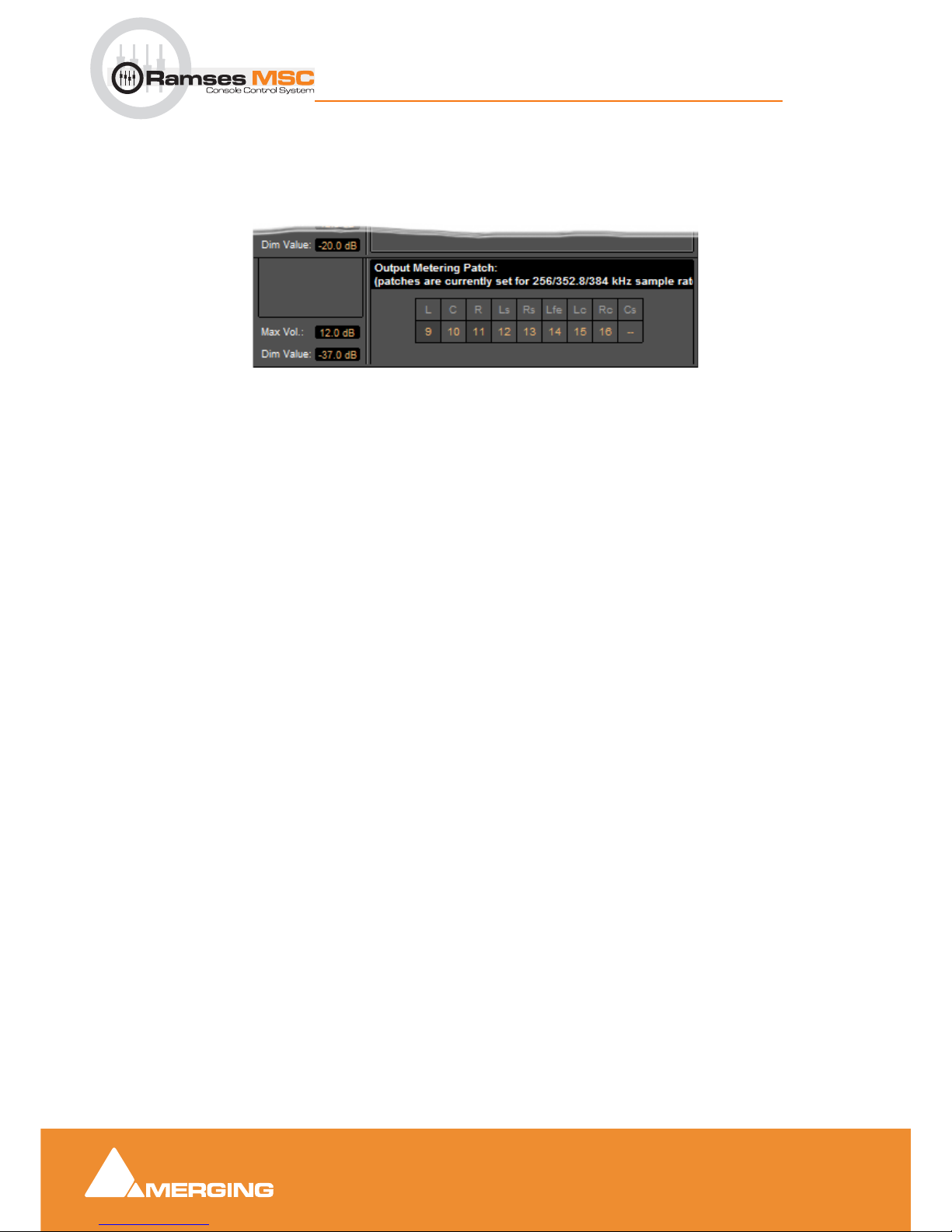
Pyramix Monitor Section
9 - 70
Ramses MSC reference guide
Pyramix Monitor Section : External Metering
External Metering
If you wish to use your favourite external hardware meters with Pyramix this can be achieved easily and
conveniently.
At bottom right of the
Monitor Configure page an extra set of nine patches is provided to configure exter-
nal outputs specifically for metering.
Patches are made in exactly the same way as the Speaker
Output Patches. Please see: Output Patch:
on page 68
Monitor Configure Output Metering Patch
Page 71
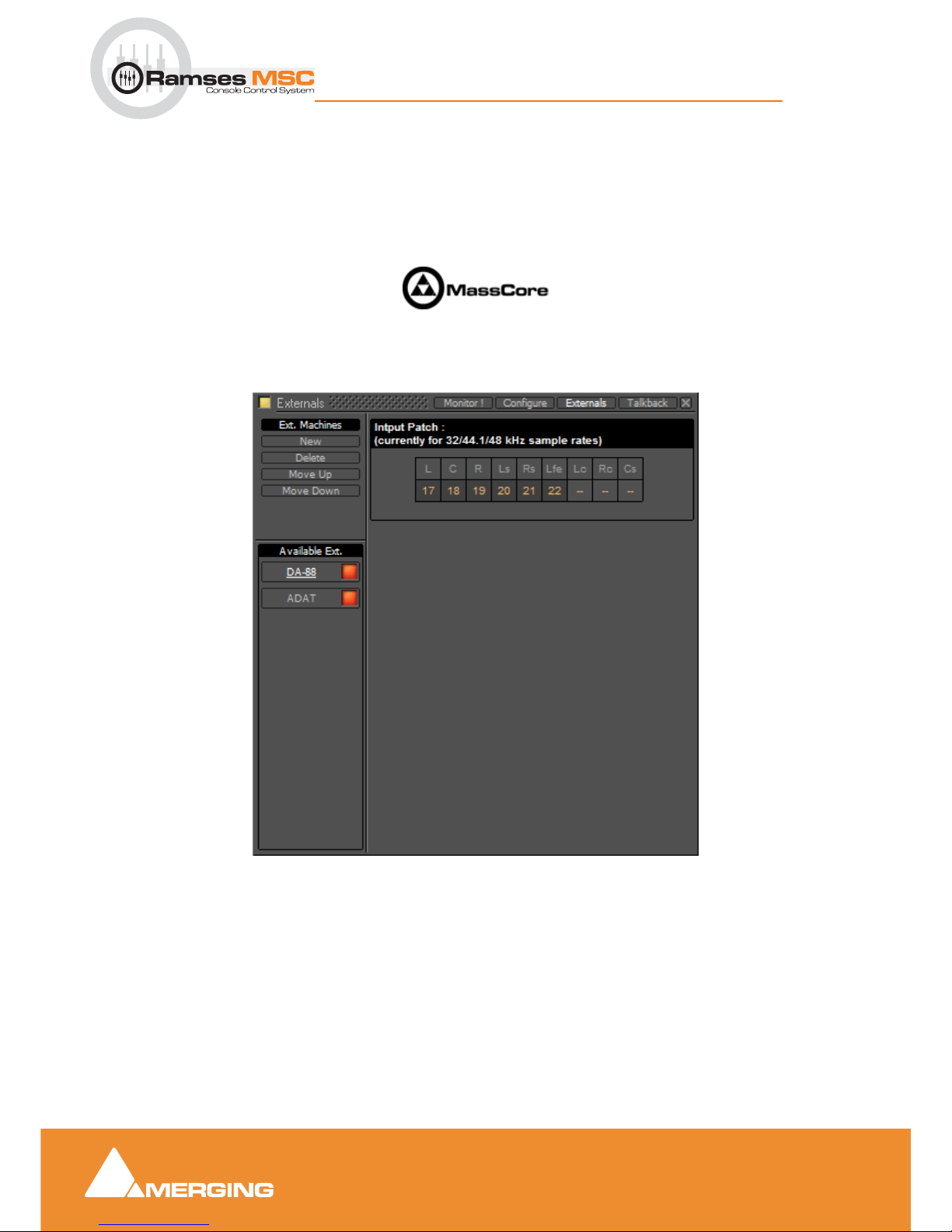
Pyramix Monitor Section
9 - 71
Ramses MSC reference guide
Pyramix Monitor Section : External Inputs
External Inputs
External devices may be added in the Monitor panel. This is useful for connecting monitoring returns from
the Studio’s fixed external audio devices such as recorders.
Note: This feature is currently available for Native, Mykerinos mono-board and MassCore
systems. It is not currently supported on Mykerinos multi-board non MassCore systems.
Adding an External Machine
Up to 8 new externals can be added.
Note: External machines will only be visible and available as monitor sources in the Monitor ! page when the Buses /Externals button is set appropriately. Please see: Buses /
Externals button on page 63
Each external has a dedicated input Patch. Patches are set up by clicking in the boxes below the speaker
letters and choosing inputs from those available.
Monitor Externals page
Page 72
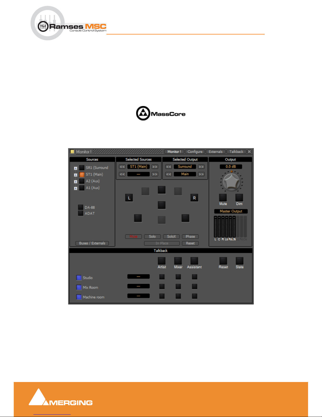
Pyramix Monitor Section
9 - 72
Ramses MSC reference guide
Pyramix Monitor Section : Talkback
Talkback
Talkback facilities are provided in the Monitor section for studios without a separate talkback system.
These facilites are intended to be used with
GPI/O external connections for physical talkback switches.
Please see: the main Pyramix User Manual, GPI/GPO Support for information about setting up GPI/Os.
Note: Talkback is currently available for Native, Mykerinos mono-board and MassCore
systems. It is not currently supported on Mykerinos multi-board non MassCore systems.
When Talkback is set up and active the Talkback section appears at the bottom of the main Monitor !
page:
Monitor ! page with Talkback Section
Page 73
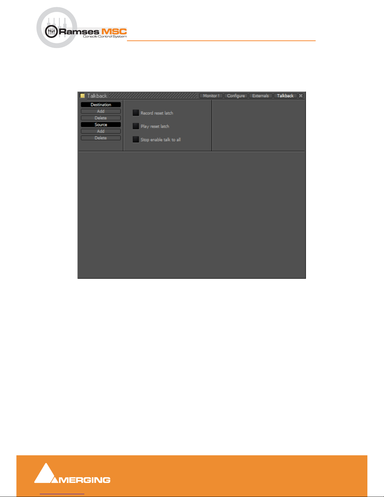
Pyramix Monitor Section
9 - 73
Ramses MSC reference guide
Pyramix Monitor Section : Talkback
Setting Up
Talkback Page
You can add up 8 Studios (Destinations) and 3 Talkbacks (Sources) in the Talkback page:
Destination
Add Adds a Destination
Delete
Deletes the selected Destination or the remaining one when there is only one shown.
Source
Add Adds a Source
Delete
Deletes the selected Source or the remaining one when there is only one shown.
Record reset latch
When lit red all active conversations are muted when the transport is in Record.
Play reset latch
When lit green all active conversations are muted when the transport is in Play
Stop enable talk to all
When lit yellow the Talk To All function is activated when the transport is in Stop.
Monitor Talkback page
Page 74
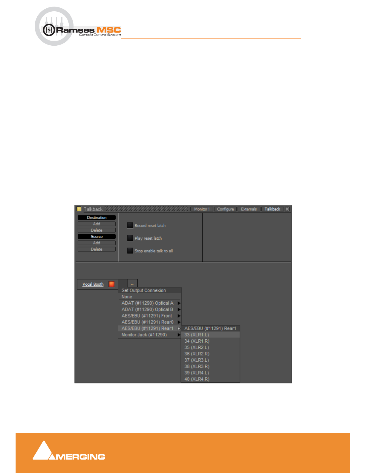
Pyramix Monitor Section
9 - 74
Ramses MSC reference guide
Pyramix Monitor Section : Talkback
Example
This is how you would set up talkback for a simple facility with a Mix Room, Studio and Machine Room.
•The
Mixer will be able to speak to the Vocal Booth or the Machine Room independently.
•The
Assistant will only be able to speak to the Mix Room.
•The
Voca l B o oth will only be able to speak to the Mix Room.
Note: If a seperate ‘Producer’ Talkback unit is required this can be achieved with a simple
parrallel physical connection of buttons that both activate the Mixer to Vocal Booth GPI.
Setting Up
1. Click on Studio Add
A New Monitor Studio box appears. Type a suitable name for the Studio, in this case, Vocal Booth
and press the keyboard Enter key to confirm.
The red button indicates that the destination is active.
Note: The Talkback section will be shown at the bottom of the Monitor ! page if any destinations are active in the Talkback page.
2. Notice the two boxes to the right of the name with orange dashes. Click on the left box to drop down the
Set Output Connection menu:
3. choose a suitable physical output to feed the Talkback amplifier/loudspeaker.
Note: If you only have digital outputs then you will need a converter.
Monitor Talkback page Destination Output Connection
Page 75
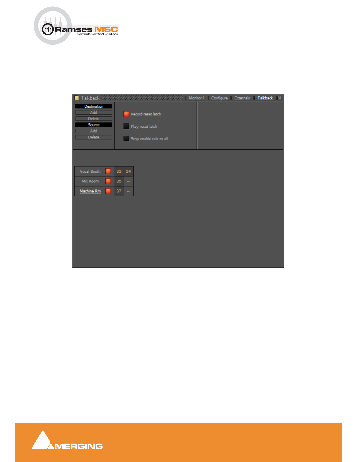
Pyramix Monitor Section
9 - 75
Ramses MSC reference guide
Pyramix Monitor Section : Talkback
4. If you wish to have stereo talkback/foldback repeat steps 2&3 for the right-hand box. Here only the
Vocal Booth is to be fed with Foldback so that is the only stereo destination.
5. Repeat steps 1 to 3 twice to add two more destinations.
6. Label these to suit, in this case, Mix Room and Machine Room.
You should now have something like this on screen:
Note: Only the Vocal Booth has been set up as a stereo destination. If you want seperate
speaker and headphone feeds to the studio just add another destination and label it appropriately. E.g Vocal Booth HP for maximum control.
7. Now set up the sources by clicking on Source Add
8.
A column appears with New Talker highlighted in a box. Type a suitable name for the source. In this
case
Mixer.
Monitor Talkback page with destinations
Page 76
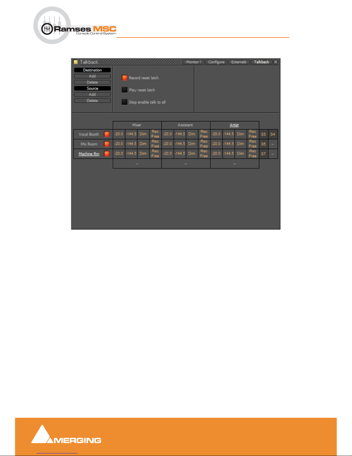
Pyramix Monitor Section
9 - 76
Ramses MSC reference guide
Pyramix Monitor Section : Talkback
9. Add two more sources and label them Assistant and Artist
10.
Click on the boxes with the orange dashes at the bottom of each source column to open the Set Input
Connection
menu and choose a suitable input connection for each of the talkback microphones.
Note: If you only have line level analogue inputs you will need external mic pres and if you
only have digital inputs then you will need converters as well.
11. Now the levels, Dim and Mute switching must be set.
• The boxes in the first column of each
Source set the attenuation that will be applied to the
Destination output when Talkback is activated from each source.
• The second column sets the send level per
Destination. You can type mute or a numeric
value in the box.
Note: If mute or -144.5 is entered this Destination will be grayed out and unavailable in
the Talkback section of the Monitor page. For example, it is illogical for the Mixer Source
to talk to the Mix Room Destination and so on.
• The third column offers the choice of Dim or None. Selecting Dim means that when this cros-
spoint (
Source to Destination) is activated by pressing the relevant Talk button, the Main
Monitor Output
will be dimmed.
Note: This is essential when, for example, the Mix Room talks to the Vocal Booth with the
programme mic channel open to avoid howl-round and possible damage to loudspeakers
and hearing.
Monitor Talkback page with Sources and Destinations
Page 77
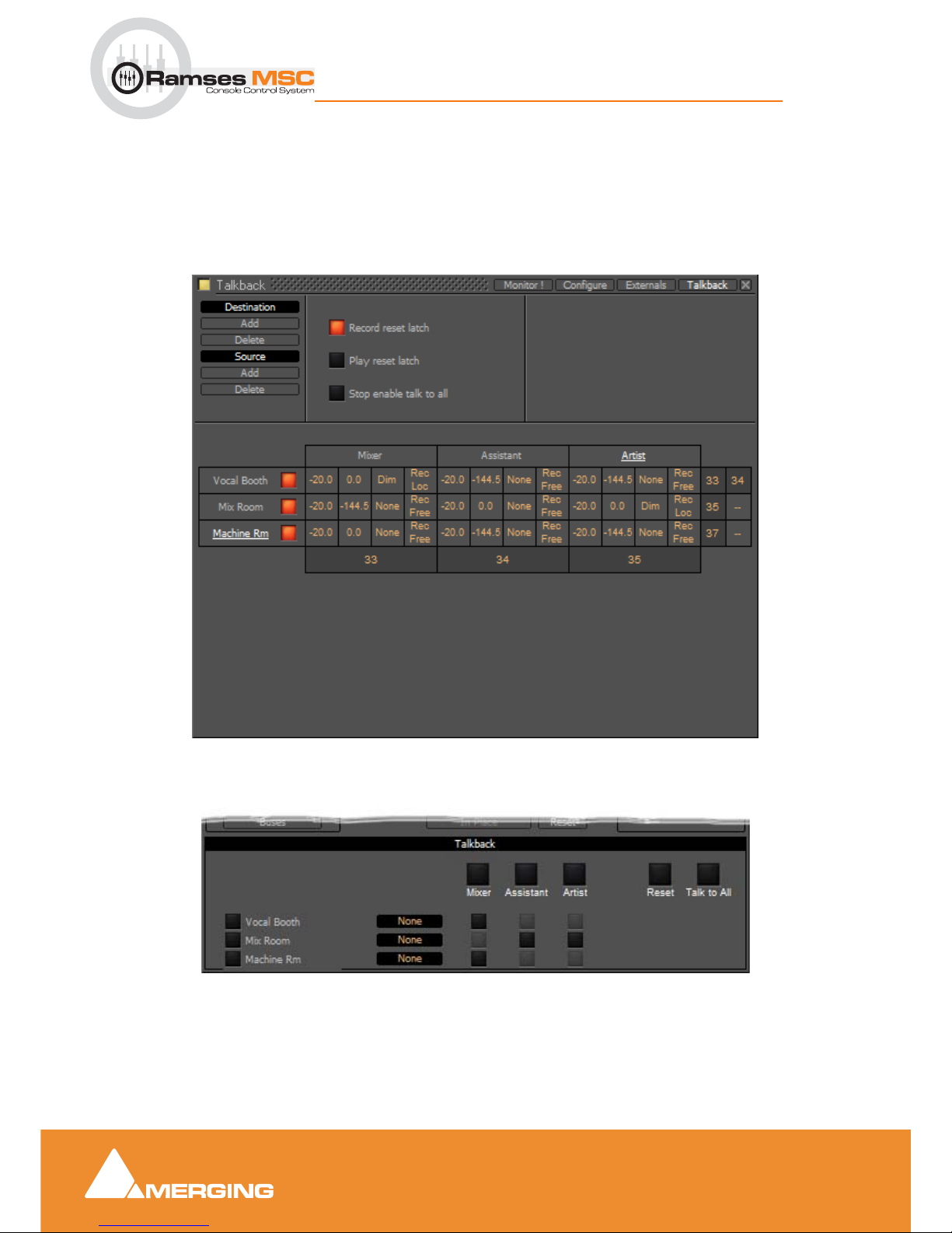
Pyramix Monitor Section
9 - 77
Ramses MSC reference guide
Pyramix Monitor Section : Talkback
• The fourth and final column offers a choice between Rec Free and Rec Loc.
Rec Free means that talkback on this crosspoint can be initiated when the Transport is in
Record and the
Record Reset Latch is set.
Rec Loc disables the crosspoint when when the Transport is in Record and the Record Reset
Latch
is set.
So, bearing in mind who is going to be allowed to talk to whom and given that it is illogical to use talkback to
talk to yourself, the levels should now look approximately like this:
Returning to the
Monitor ! page you will see this in the Talkback section:
(If the buttons on the left are lit blue ignore them for now) The big buttons with the labels
Mixer, Assistant
and
Artist are Talk to All destinations (In this case only relevant to Mixer)
Monitor Talkback page with Sources and Destinations and levels set
Monitor ! page Talkback Section
Page 78
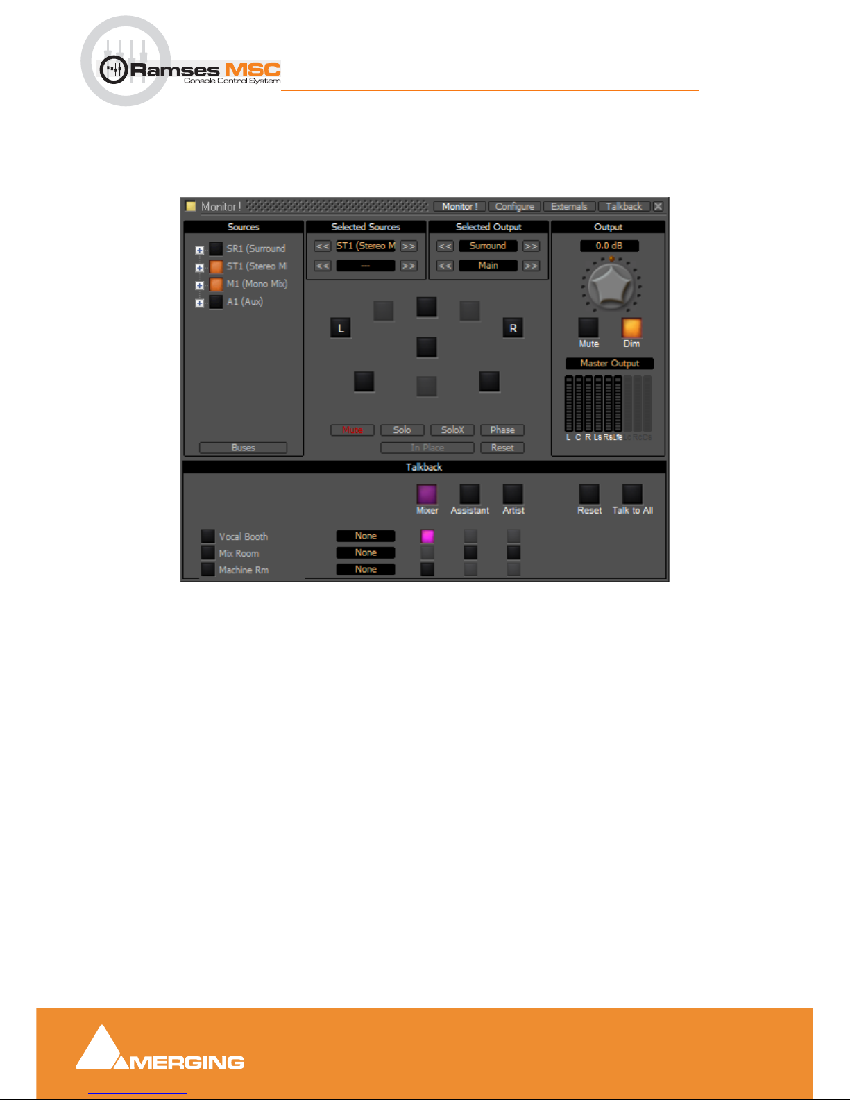
Pyramix Monitor Section
9 - 78
Ramses MSC reference guide
Pyramix Monitor Section : Talkback
Operation
The smaller buttons vertically below the bigger, labelled Source buttons initiate talkback from the horizontal
sources to the vertical destinations. These are the buttons you are most likely to want to map to
GPIs. For
example in the following screenshot the
Mixer is talking to the Vocal Booth:
Note: Notice that, due to the settings made earlier, Mixer talking to Vocal Booth also
Dims the Main Monitor Output.
Talkback Button Operation
All the Talkback buttons are dual mode. A press of less than one second latches the Talkback open. A second press cancels. A press of more than one second initiates Talkback on press and cancels when the button is released.
Reset cancels all latched talkbacks.
Talk to All initiates open Talkback between all enabled Sources and Destinations
Monitor Talkback page : Mixer talking to Vocal Booth
Page 79
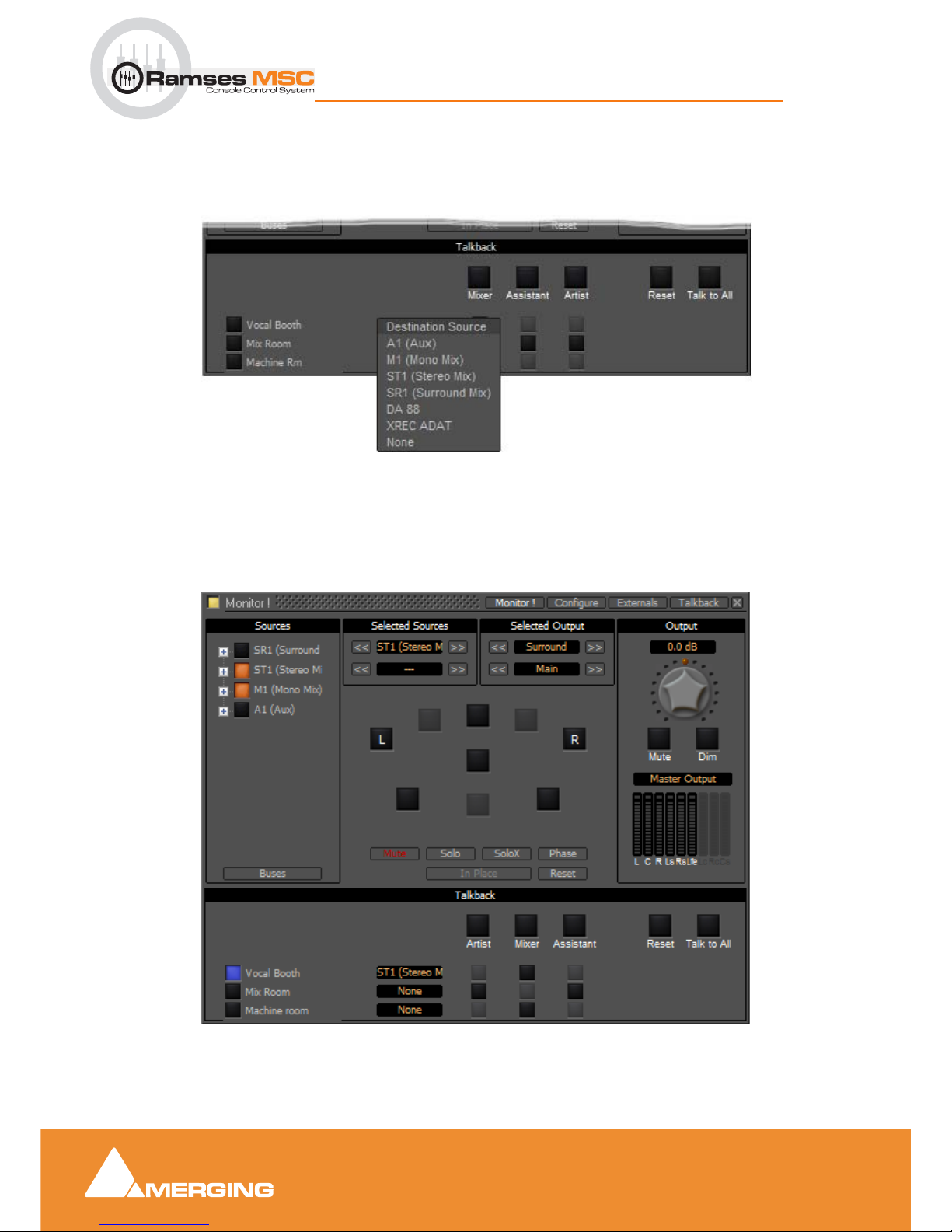
Pyramix Monitor Section
9 - 79
Ramses MSC reference guide
Pyramix Monitor Section : Talkback
Foldback
Continuing the foregoing Talkback example it is also possible to add foldback to the Talkback outputs. To
add Foldback to the
Vocal Booth Talkback outputs click on the black box to the right of the Vocal Booth
label to drop-down a list of available Foldback sources:
Select the required
Foldback Studio Monitor Source.
Note: You can add a bus in the mixer specifically to produce a mix for Foldback.
The buttons on the left of the Vocal Booth label etc. toggles the foldback on and off per destination:
Here, the
Voca l B o oth is fed with ST1 (Main) bus output. The vocals are recorded clean on M1 (Mono
Mix)
and, as can be seen above, the Mixer Room monitors are being fed with the sum of these buses.
Monitor Talkback page : Select Foldback Source
Monitor Talkback page : Foldback to Vocal Booth Active
Page 80
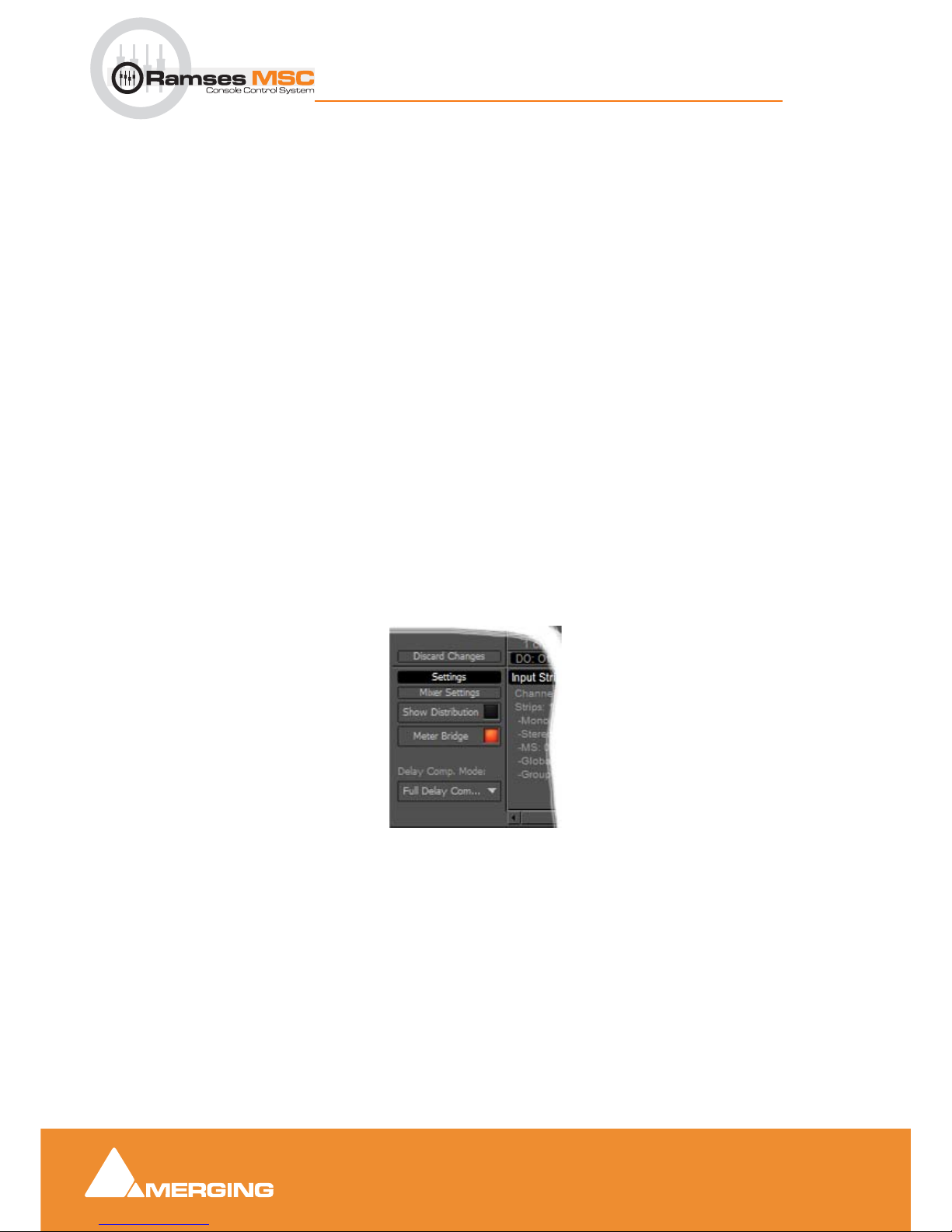
Meter Bridge
10 - 80
Ramses MSC reference guide
Meter Bridge : Scope
10 Meter Bridge
Scope
Ramses MSC takes full advantage of the Pyramix dedicated Meter Bridge window.
The
Meter Bridge can present a meter display for every Input strip and Bus present in the current Mixer
and external Machine configured in the
Monitor : Externals page.
The
Meter Bridge also indicates the currently selected mixer strip with a yellow outline, any strips in
Record Ready condition with a red outline, whether any strips are
Muted or Soloed and optionally shows
Ramses Groups and Fader
Automation mode per strip.
You do not have to use the
Meter Bridge but, especially when used with Ramses MSC, it offers flexible
metering in one place. With complex Mixers and routing, the Meter Bridge can help to keep things logical.
Note: The Meter Bridge is displayed “Always On Top” of other windows.
Meter Bridge Switch
Before the Meter Bridge Window can be opened it must be switched on in the Settings section of the Pyra-
mix
Mixer Configure Page :
Meter Bridge Switch
Page 81
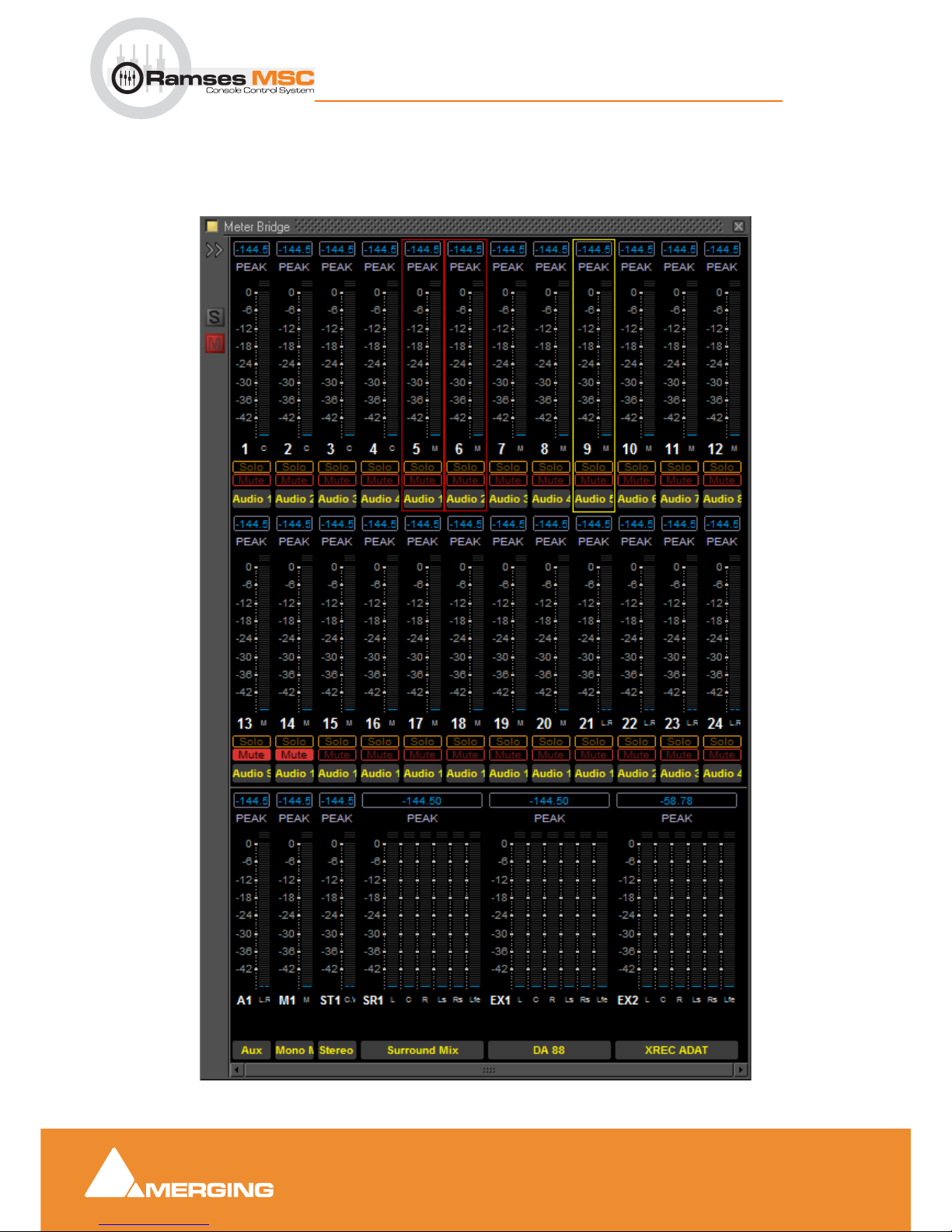
Meter Bridge
10 - 81
Ramses MSC reference guide
Meter Bridge : Meter Bridge Window
Meter Bridge Window
By default the Meter Bridge window is hidden. It can be opened with View > Meter Bridge or the icon in
the View
Toolbar.
Meter Bridge Window - Triple Row Mode
Page 82
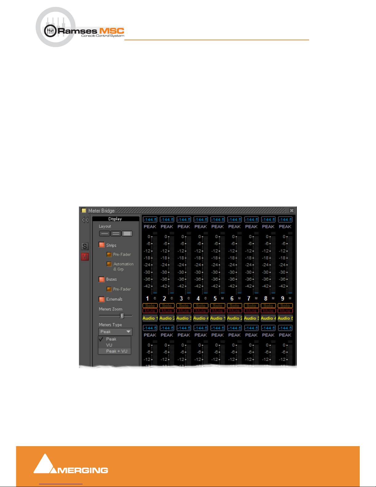
Meter Bridge
10 - 82
Ramses MSC reference guide
Meter Bridge : Meter Bridge Window
Resize
The Meter Bridge Window can be resized by clicking and dragging the edges. (Mouse cursor changes to
double arrow) Vertical resizing is limited to sensible display options. Scroll bars will appear when there is
more information to display than the window can accomodate.There is a separate auto-hide scrollbar for
the Input Strips so you can keep all the Buses and Externals visible together with a contiguous section of
the Input Strips of a very large mixer. (This will appear when the mouse cursor is over the right-hand edge
of the top two rows.)
Global Mute and Solo Indicators
If any strip is Muted or Soloed the global indicators in the left margin illuminate.
Selected Strip and Record Ready Status
The currently selected strip is shown with a yellow outline.
Any strips currently in Record Ready mode are shown outlined in red.
Configuring the Meter Bridge
When first opened the Mixer Bridge appears as above. clicking on the double arrow >> below the Yellow
Activate button opens the
Display panel (a subsequent click on the << arrows closes):
Layout
The three buttons determine whether the meters are displayed as a single, double or triple row (default).
Meter Bridge Configuration : Display Section
Page 83
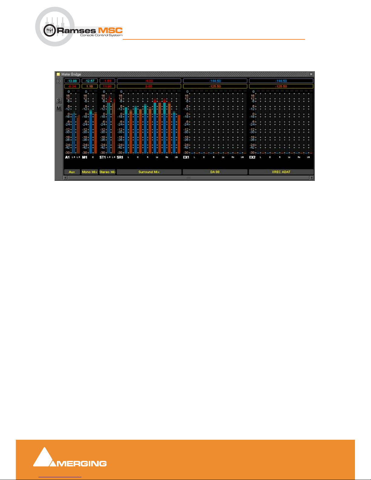
Meter Bridge
10 - 83
Ramses MSC reference guide
Meter Bridge : Meter Bridge Window
Single Row
Single row is useful if you only wish to display buses and or Externals (returns).
Strips
The red button shows/hides the Input Strip Meters (default is Show)
Note: Show/Hide for Input Strips is only available in ‘single row’ display mode. Useful in
applications where the Bus and External Machines are of more interest than the Inputs.
Pre-Fader
When lit, the Input Meters source is taken pre-fader. (default is post-fader)
Automation
When lit, four Fader Automation Mode indicators are shown in each Input Strip. (default is hidden)
Buses
The red button shows/hides the Bus Strip Meters (default is Show)
Pre-Fader
When lit, the Buses Meters source is taken pre-fader. (default is post-fader)
Externals
The red button shows/hides the External Machines Meters (default is Show)
Note: Externals, External machine Returns, are set up in the Pyramix Monitor : Externals page.
Meters Zoom
The slider adjusts the meter scaling. Range is from 0dB to -144.5dB maximum to 0dB to -10dB minimum.
Double-clicking on the slider ‘knob’ resets to default scaling.
Meter Bridge - Single Row Mode
Page 84
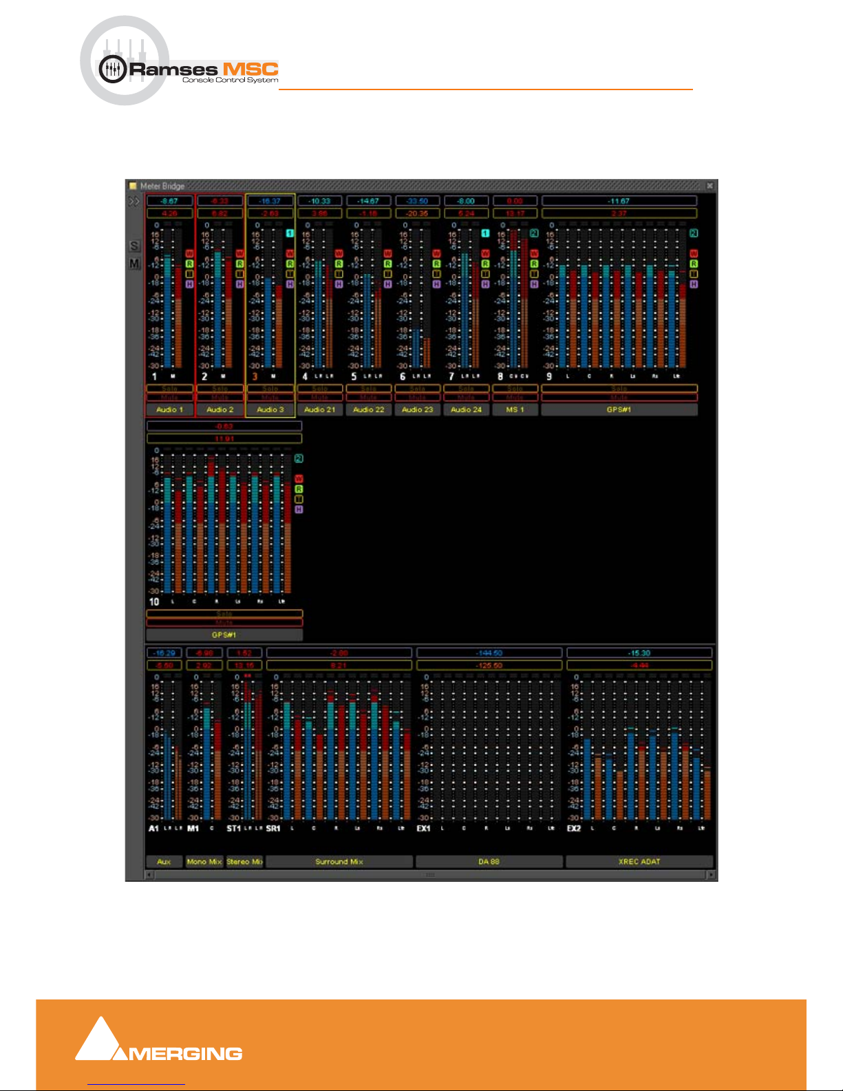
Meter Bridge
10 - 84
Ramses MSC reference guide
Meter Bridge : Meter Bridge Window
Meters Type
The drop-down offers a choice between Peak (default), VU or Peak + VU as seen here along with the
Automation Indicators
:
Meter Bridge - Triple Row Mode
Page 85
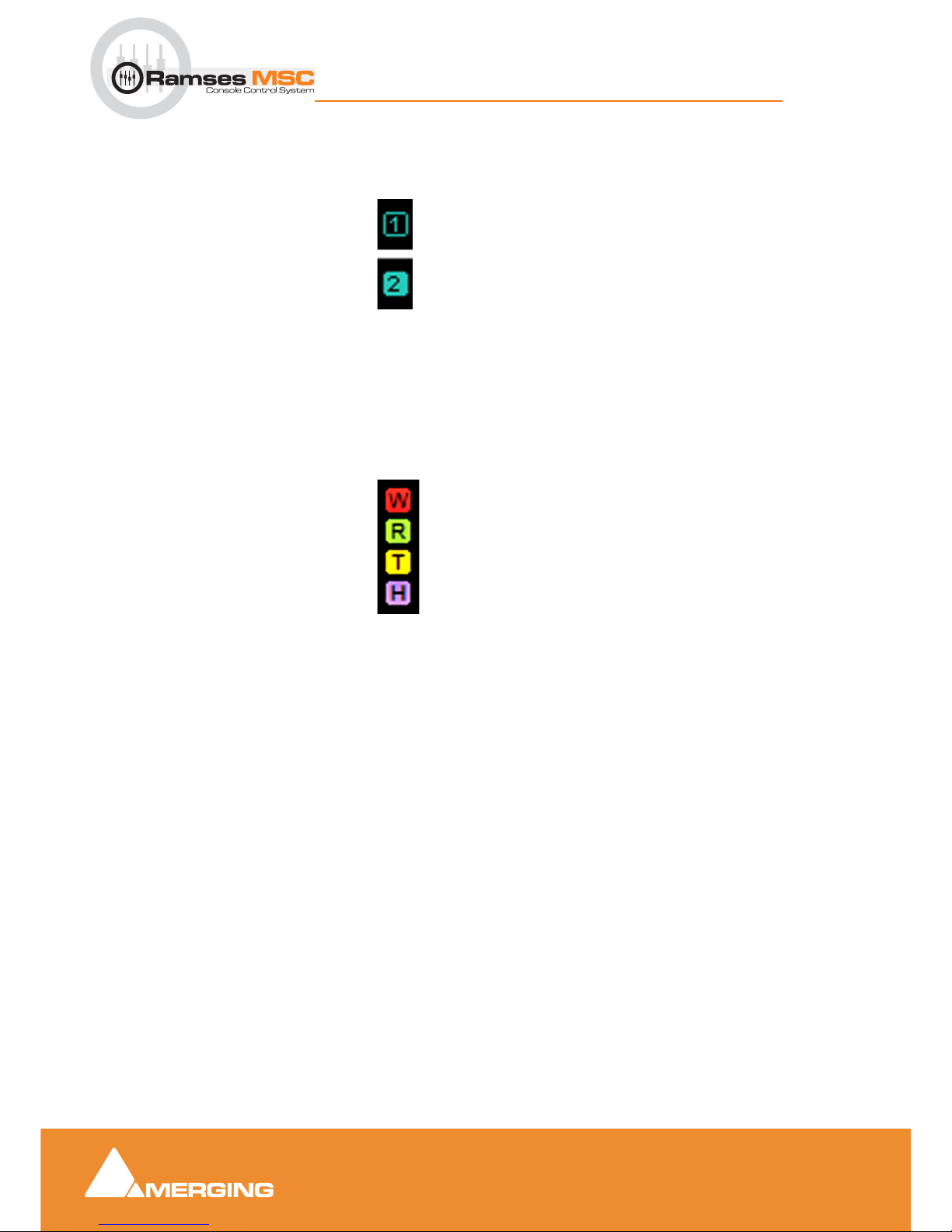
Meter Bridge
10 - 85
Ramses MSC reference guide
Meter Bridge : Meter Bridge Window
Automation Fader Mode and Group Indicators
Ramses Group
This indicator shows that the associated strip is a member of a Ramses MSC control Group. When in
inverse video (filled in) it also indicates that the associated strip is a member of the currently selected strip’s
Group.
Note: These Ramses MSC Control Groups are currently completely independent of the
Pyramix grouping arrangements.
Automation Fader Mode
In the default, Auto-Write, mode only the Write and Read indicators are lit together.
As soon as a fader is touched with the transport in play the
Read indicator extinguishes leaving only the red
Write indicator lit.
If an Automation
Trim mode is selected the yellow Trim indicator will also be lit.
Similarly, if a
Hold mode is selected the purple Hold indicator will be lit.
Thus, in the
Meter Bridge screenshot above, the automation is in Auto-Write plus Trim & Hold modes.
Member of Group
Member of selected
Strip’s Group
Write
Read
Trim
Hold
Page 86

Edit Bay
11 - 86
Ramses MSC reference guide
Edit Bay : Introduction
11 E d i t B a y
Introduction
Scope
The edit bay will function as described in this document, although please bear in mind that functions will be
added in the coming months to arrive at the full functionality of Edit Bay as labelled on its surface.
We have developed workarounds for the few remaining functions not yet available.
All functions
NOT described in this quick start guide are already fully functional as they will be in the final
version. Please refer to the labelling on the Edit Bay surface and to the Pyramix 6.0 user manual for the
specifics.
Software Versions
Important Note:
It is ESSENTIAL to have the following versions of software or later to avoid unpredicatable
operation:
• Pyramix Version 6.0.4 Pre RC1 build 323
• Ramses Consolesoft 1.5.3 3709 14th November 2007
• Edit bay Consolesoft set2 21st November 2007
Please refer to the Ramses update guide and Pyramix 6 Installation Guide for guidance on how to install
those updates.
Page 87
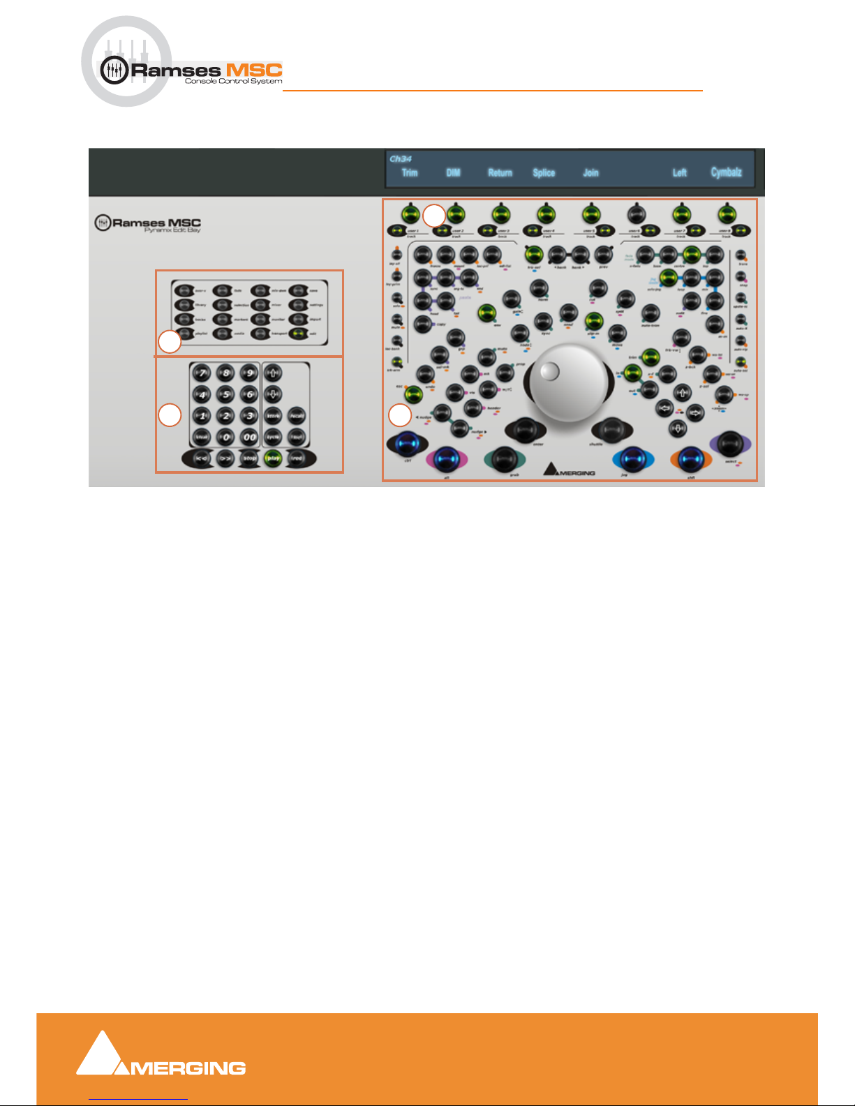
Edit Bay
11 - 87
Ramses MSC reference guide
Edit Bay : General Overview
General Overview
1. View Select and Modifiers; These keys open Pyramix Windows and dialogs such as All Settings and
the
Fade Editor or Library Tab Windows. In a later iteration of software the Editor will have the focus
on those windows when they are opened.
2. Transport Control; This is the same as theTransport Control panel on the main Ramses MSC surface
with the same functions available.
3. Track Selection and User keys; these keys are used to select a Trac k, or to Mute, Arm etc. a track
depending on which Modifier they are temporarily assigned to. It is closely linked to the above VCD
(alphanumeric feedback) and will be in the future available for User Defined Macros and Functions.
4. Editor; all the functions needed to edit quickly and efficiently are labelled on the surface. The big but-
tons at the bottom of the panel are used to select the
Jog Mode and Modifiers (Ctrl, Alt etc) to provide
greater functionality. When the Modifiers are pressed and held the available functions will light up on
the editor.
Ramses MSC Edit Bay Panel
4
2
3
1
Page 88
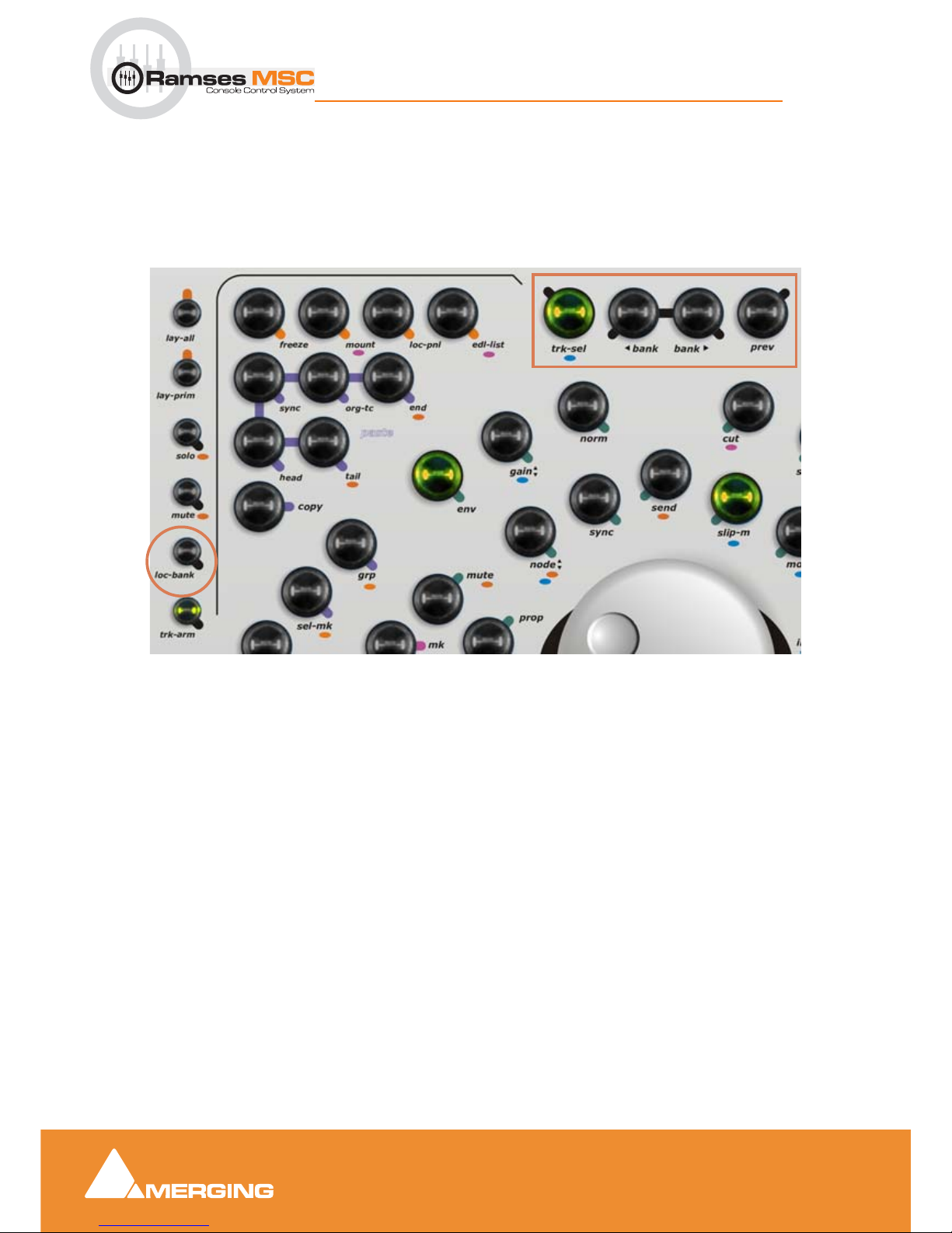
Edit Bay
11 - 88
Ramses MSC reference guide
Edit Bay : The Editor
The Editor
Note: ONLY FUNCTIONS WHICH ARE NEW AND NOT FULLY OR PARTIALLY IMPLEMENTED (WORKAROUNDS) WILL BE DESCRIBED
Navigation
You can navigate independently OR with the Ramses fader/strips navigation.
When
loc -bank is disabled you will navigate in combination with the Ramses fader strip navigation. The
right-most eight faders will also be the
Edit Tracks shown on you VCD available for Selection and Editing.
When
loc-bank is enabled navigation around the Edit Tracks is independent of your Ramses.
Note: Please remember that in order for the Navigation keys on the Edit Bay to work you
must enable loc-bank.
trk-sel - press and hold to use the jog wheel to navigate through the Edit Tracks
< bank- each time you depress the VFD shows the previous eight Edit Tracks
> bank- each time you depress the VFD shows the next eight Edit Tracks
prev- not yet implemented. Jumps to previous Edit Track layout
Note: You can also touch a fader on Ramses and the corresponding Edit Track will be
highlighted automatically. Another way of navigating is to use the up and down arrows to
move from one Edit Track to the previous / next.
Edit Bay Panel Navigation area
Page 89
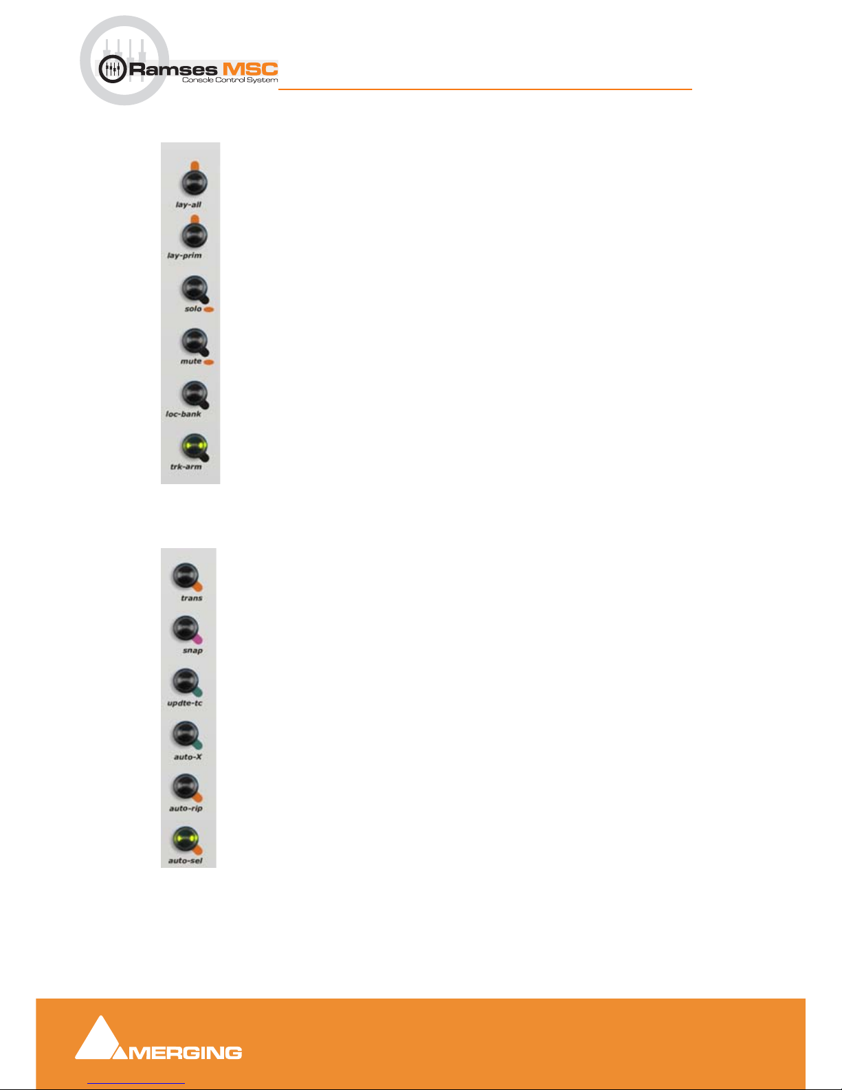
Edit Bay
11 - 89
Ramses MSC reference guide
Edit Bay : The Editor
Modifiers - Left-hand Side
lay-all not yet implemented
lay-prim not yet implemented
solo when pressed the small Track Selection and User Keys will
toggle Solo on the Edit Tracks
mute when pressed the small Track Selection and User Keys will
toggle Mute on the Edit Tracks
loc- bank Toggles linking navigation to Ramses main fader navigation
trk-arm when pressed the small Track Selection and User Keys will
toggle Track Arm on the Edit Tracks
Modifiers - Right-hand side
trans not yet implemented
snap enables Snap Head to Nearest. CTRL + snap disables Snap
Head to Nearest
update-tc Updates the original TimeCode of the actual composition to
the original medias.
Use with caution!
auto-x
toggles auto cross fade enable/disable
auto-rip toggles auto-ripple (shuffle) enable/disable
auto-sel auto selection mode (Clip - and Clip group - under cursor)
when Stopped or when another another Edit Track is
selected
Page 90
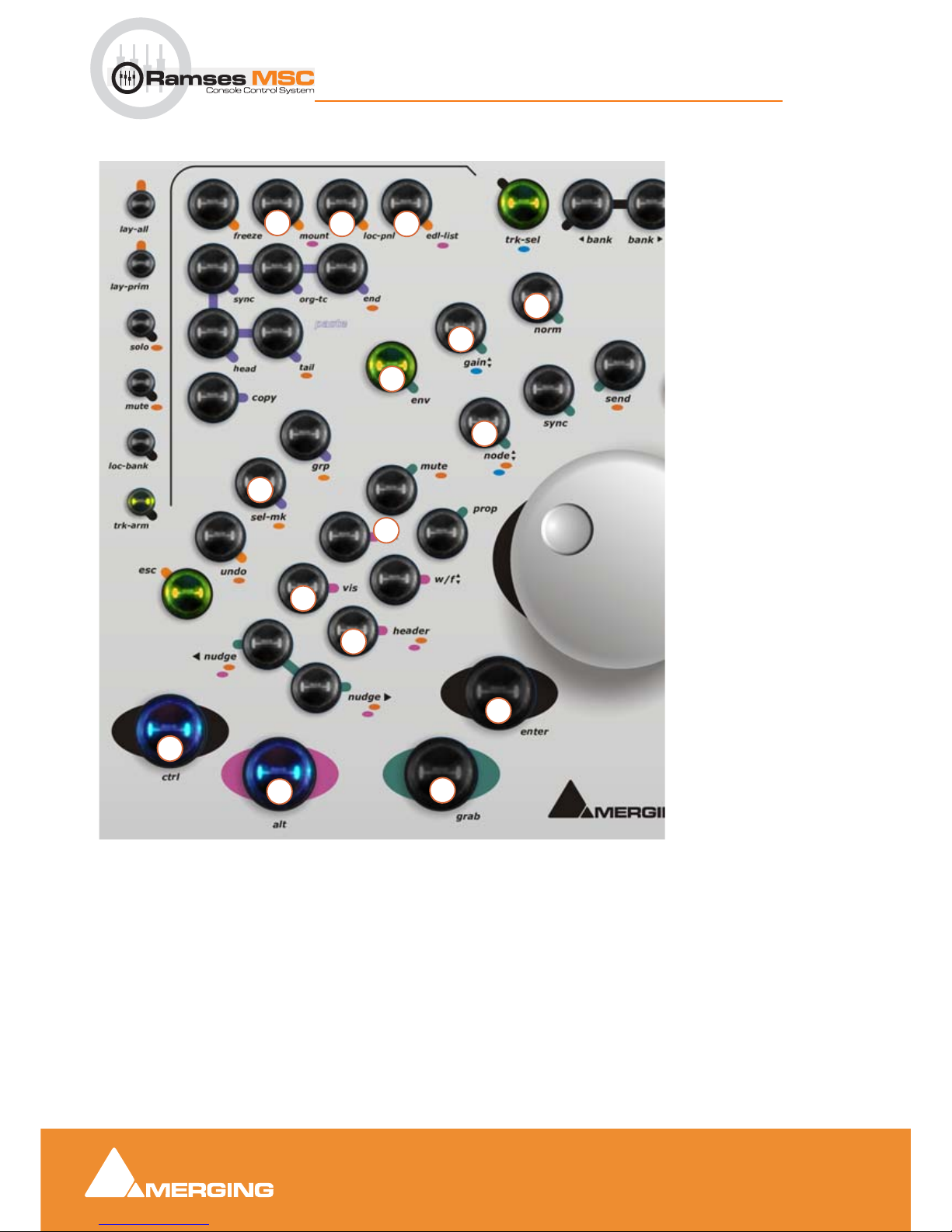
Edit Bay
11 - 90
Ramses MSC reference guide
Edit Bay : The Editor
Editor - Left-hand side
1. Mount referenced Media
Files/More options to come
2. Lock Edit Panel/not yet
implemented
3.3.opens edl list/more
options to come
4. Select Next Marker,
+Ctrl select previous
marker
Shift move
selected Marker to Cursor/
More options to come
5. Normalize Clip or selec-
tion of Clips keeping relative gain/More options to
come
6. Adjust Clip Gain with
fader/More options to come
7. Inactive for now / Enve-
lope not yet implemented
yet
8. Visible/Invisible track/
not yet implemented
9. Track Header/ not yet
implemented
10. Ctrl modifier as on key-
board
11. Alt modifier as on key-
board
12. Clip & Media grab from
Libraries and Media Manager / not yet implemented
13. ENTER as on keyboard
14.1deactivated for now /
Envelope not yet implemented
17
9
11
14
10
8
7
6
5
4
2 3
12
13
1
Page 91
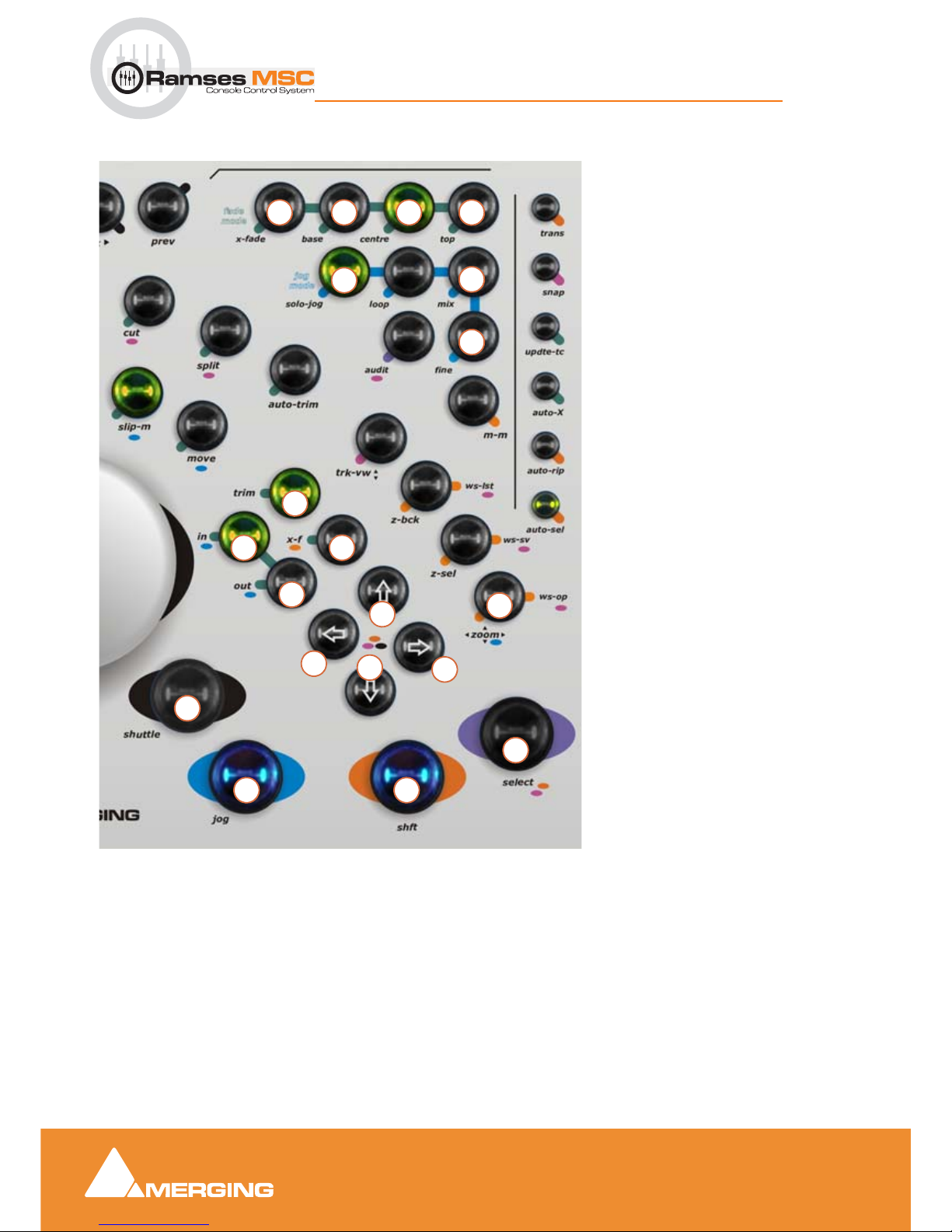
Edit Bay
11 - 91
Ramses MSC reference guide
Edit Bay : The Editor
Editor - Right-hand side
1. Opens X-Fade Editor / more options
to come
2. Inactive for now / not yet implemented
3. Inactive for now / not yet implemented
4. Inactive for now / not yet implemented
5. Solos selected track when jogging
6. Listen to all when jogging
7. Toggles fine jog mode
8. Zoom with jog wheel / not imple-
mented yet with up-down & left-right
arrows
9. In & Out point selection of region or
clip /
+ Ctrl cuts In & Out to Playhead /
more options to come
10. Trim In (jog)/ + Ctrl Trim Out / more
options to come
11. Fade In (jog) / + Shift Fade Out /
more options to come
12. Up-Down / + Ctrl Move Selection /
+ Alt Move Clip /more options to come
13. Left-Right / + Ctrl Select PreviousNext
Clip / + Alt Goto Previous-Next
Edit
14.
Shuttle Mode (jog) / + Ctrl Navigate
Silent (jog)
15. Jog Mode / + Ctrl Loop Jog mode
16. Shift modifier as on keyboard
17. Select Clip Under Cursor / more
options to come
17
9 11
1615
14
10
8
7
6
5
42 3
12
13
1
9
13
12
Page 92
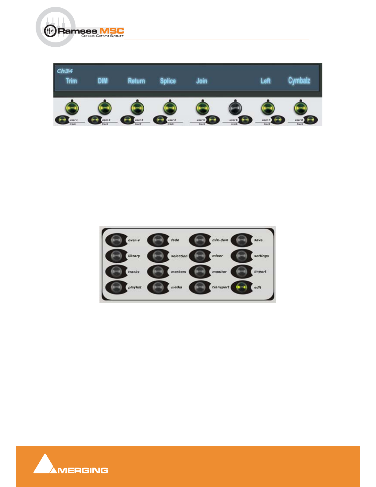
Edit Bay
11 - 92
Ramses MSC reference guide
Edit Bay : Track Selection and User Keys
Track Selection and User Keys
This is an example of the kind of functionalities and display possibilities that will IN THE NEAR FUTURE
be available on your edit bay. As of today the top part of the Alphanumeric Display is dedicated to displaying
Track Names and the bottom part for Edit Track numbers.
The big buttons select the desired
Track on which, for example, you wish to edit a Clip.
The small buttons action is dependent on which
Modifier is currently enabled on the Editor; i.e. Mute,
Solo or Track-arm. It will also be as mentioned above for future implemented user defined functionalities
View and Modifiers
All the buttons in the View and Modifier section of the Editor are functional on a basic level. Once the Edit
bay functionality is complete the aim is to use a combination of the Jog-wheel, up/down-left/right arrows
and the small buttons underneath the select buttons under the Alphanumeric screen to help navigate within
windows such as libraries and the Media Manager. This will also mean that the focus will be given to those
windows when open.
At present these Modifiers toggle Pyramix Tab Windows Open and Closed.
Note: the editor button is not functional yet.
Page 93
Pyramix Mixer
12 - 93
Ramses MSC reference guide
Pyramix Mixer : Overview
12 Pyramix Mixer
Overview
The Pyramix Mixer has evolved into an extremely powerful tool kit. The extensive range of components and
the routing and automation possibilities can be a potential source of confusion. However, the basic principles are simple and logical. Signals enter mixer strips at the bottom, go through various controls and processing to the top of the strip where they are routed to a bus or busses. The busses run horizontally and the
sum of the bus signals enters the bus master strip at the top and moves down through a master fader and
other controls to the output(s).
Native VS3, VST and External Insert plug-in effects can be inserted in input strips, aux masters and buses.
If you are new to Pyramix, use one of the simpler mixer templates to familiarize. E.g.
Mix 08 X 02 (Stereo)
Mixer Pages
The Mixer user interface is arranged in five pages grouping functions in a logical manner. Most time will be
spent working in the main
Mix ! page. The other pages, Automation, Configure, Route and Organize,
toggle with the
Mix ! screen and are accessed from buttons at top right of the screen...
Page 94
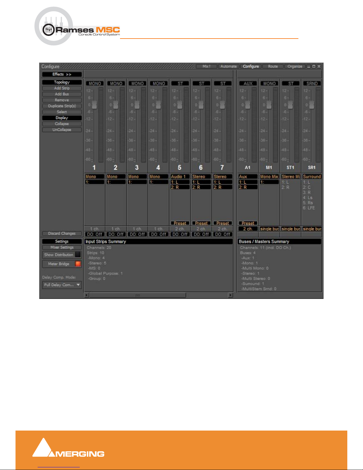
Pyramix Mixer
12 - 94
Ramses MSC reference guide
Pyramix Mixer : Configure Page
Configure Page
In the Configure page multiple changes may be made to the mixer without it rebuilding after each change.
The rebuild only occurs when you exit the page.
Settings
Mixer Settings
Opens the Mixer Settings window at the All Settings > Misc > Mixer Settings page.
Show Distribution
When on (lit), a narrow colored bar is inserted at the bottom of each input strip. This indicates which card
(in a multi-board system) is providing the DSP for the strip.
Mixer Configure Page
Page 95
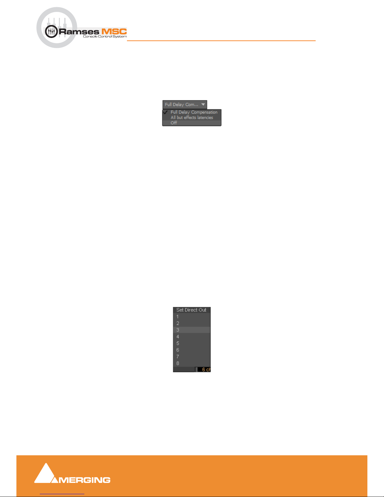
Pyramix Mixer
12 - 95
Ramses MSC reference guide
Pyramix Mixer : Configure Page
Meter Bridge
When on (lit) the Meter Bridge Window is available to be opened from View > Windows / Tools > Meter
Bridge
or the Toolbar icon. Please see: Meter Bridge on page 80
Delay Comp Mode
Drop down list menu:
Offers the choice of
Full Delay Compensation, All but effects latencies and Off.
Please see: Mixer Delay Compensation on page 120
Mixer Configuration Summaries
The two panels at bottom right summarize the current mixer configuration. Input Strip Summary lists the
total number of Channels and Input Strips and the quantity of each type.
Buses / Masters Summary lists
the total number of bus channels and buses strips with the quantity of each type.
Note: Rebuilding a large mixer with many effects can take some time.
Click and drag the separator bar between Strips and Busses to show more or less busses. The scroll bars
give access to strips currently off screen.
Direct Outputs
The Direct Out connection is disabled by default. It can be enabled in the Configuration Page by selecting
the strip and clicking on the
DO: Off box or disabled if the box shows DO: On. Alternatively Direct Out can
be set in the
Route Page by clicking on the Strip Header.
The
Direct Out can be routed by Channel to any output of the HDTDM or XDTDM bus. The Direct Out can
be sent Pre or Post Fader. Click on the
DO: Post box in the Mixer I/O section to toggle. The Direct Out is
currently always
Post Effects. For multi-channel strips clicking in the box above the DO: box pops-up a
Set Direct Out list:
Highlight the required channel. This will be fed to the logical output assigned in the
Mixer Route page or by
clicking on the
DO XLR icon in the Mix page.
Selecting Strips
Strips can be selected by clicking on the label at the top of the strip which turns orange to show it is
selected. Selection uses the conventional modifier logic: Clicking a second strip while holding
SHIFT
selects all strips in between and strips can be individually added or subtracted from a selection by clicking
Set Direct Out
Page 96
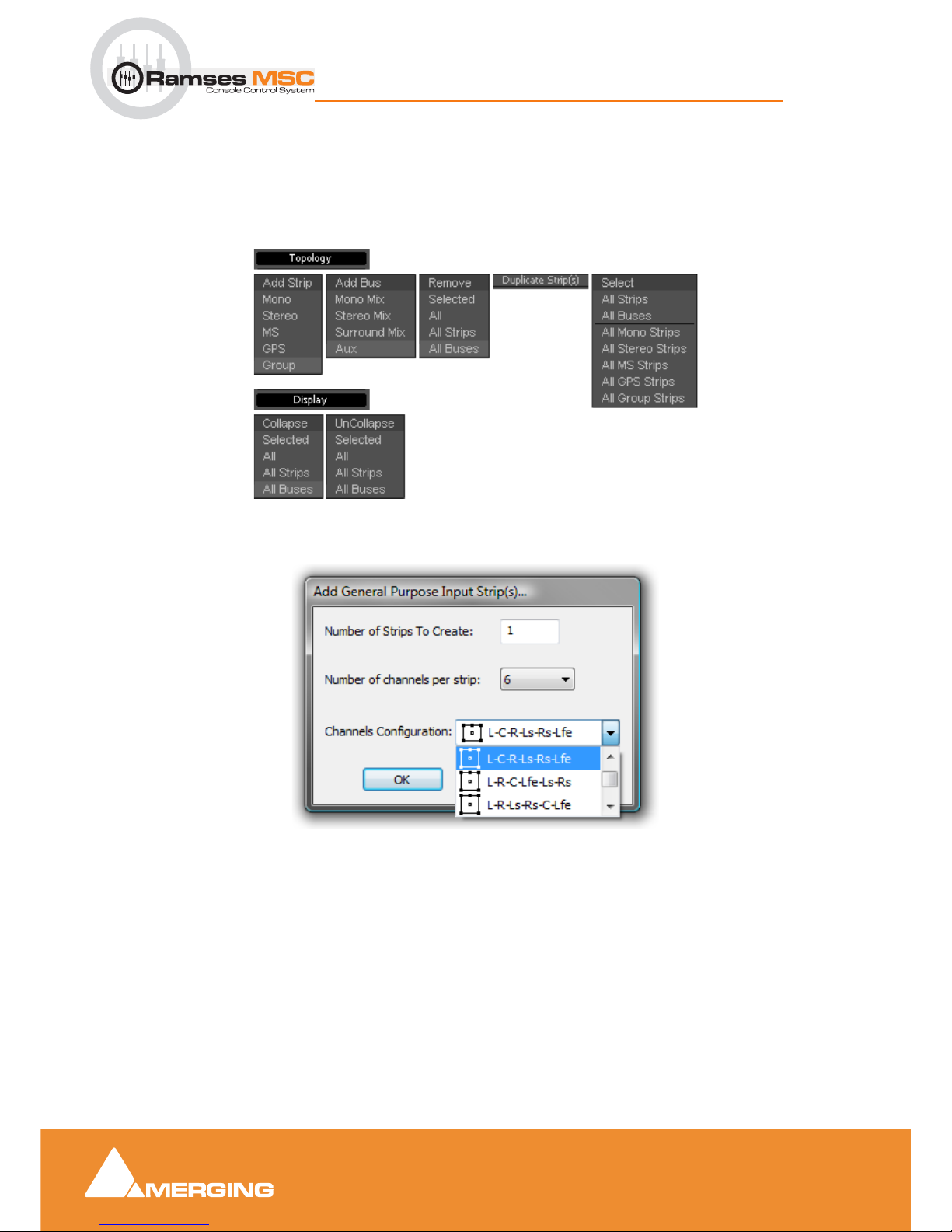
Pyramix Mixer
12 - 96
Ramses MSC reference guide
Pyramix Mixer : Configure Page
with the Ctrl key held down. Ctrl + A selects all strips. Strips can be selected by type using the Select context menu.
Strip and Bus operations
Once selected, strips can be dragged and dropped to reorganize. Other strip operations make use of the
Topology and Display menu buttons. Each button pops up a list of options:
Add Strip - Mono, Stereo, MS, GPS and Group pops up a dialog with appropriate options:
Topology and Display menus
Add General Purpose Input Strip(s) dialog
Page 97
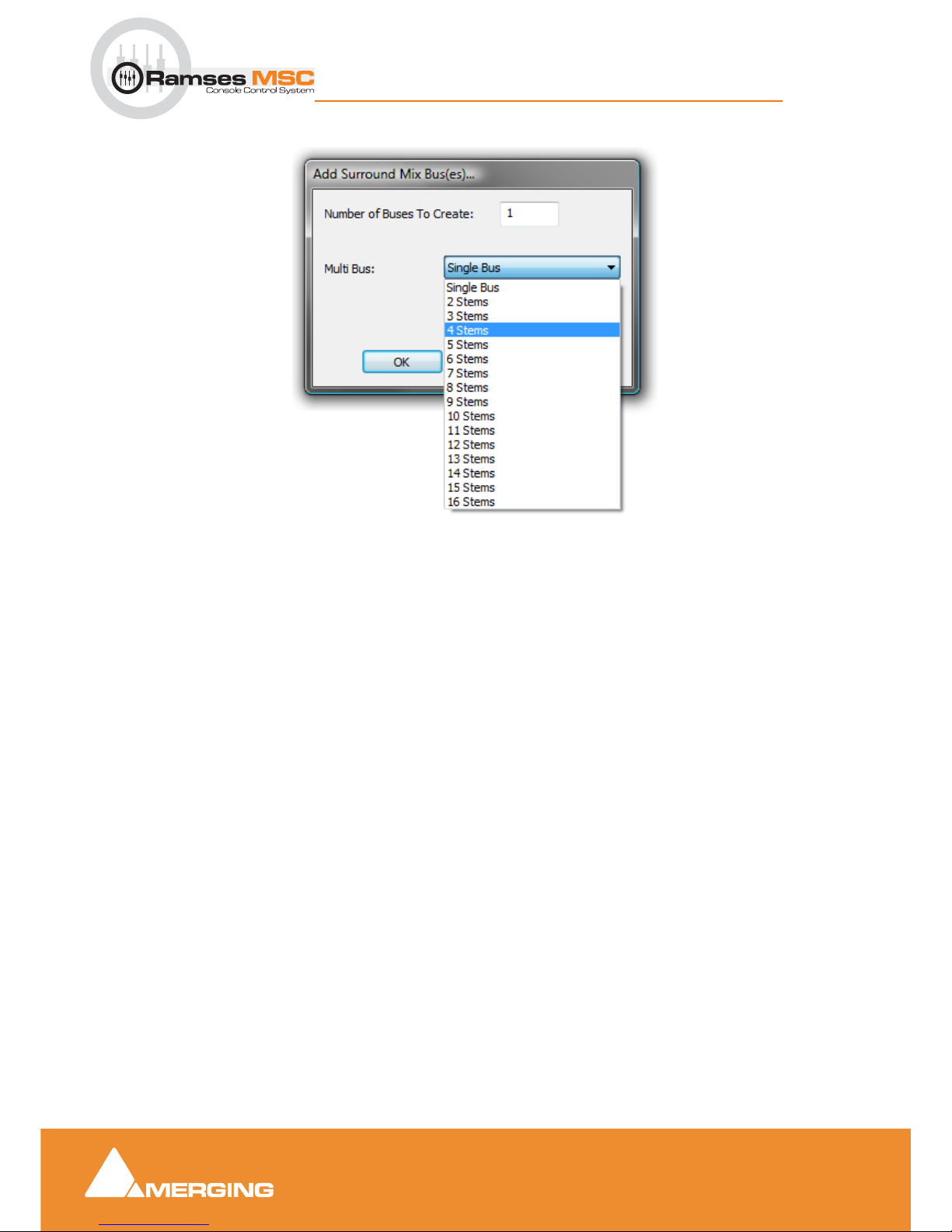
Pyramix Mixer
12 - 97
Ramses MSC reference guide
Pyramix Mixer : Configure Page
Add Bus - Mono Mix Stereo Mix Surround Mix and Aux is similar:
Duplicate Strip(s) adds a copy of the selected strip(s) to the right of the selected strip(s) including settings
(pan, gain etc.) and effects.
Select Offers selection choices to speed up configuration.
All Strips
All Buses
All Mono Strips
All Stereo Strips
All GPS Strips
All Group Strips
Productivity Shortcuts
Ctrl + A selects All Strips, DELete, deletes all selected strips.
Selected Strips can be dragged to a new location in the mixer. The screen scrolls horizontally when you hit
the edges of the Strip panel.
Double-clicking a Strip toggles it’s collapsed/uncollapsed states.
Strip names can be edited by clicking in the name box and typing.
Tab moves to the name box of the next
strip to the right,
SHIFT + Tab moves to the name box of the next Strip on the left.
Add Surround Mix Bus(es) dialog
Page 98
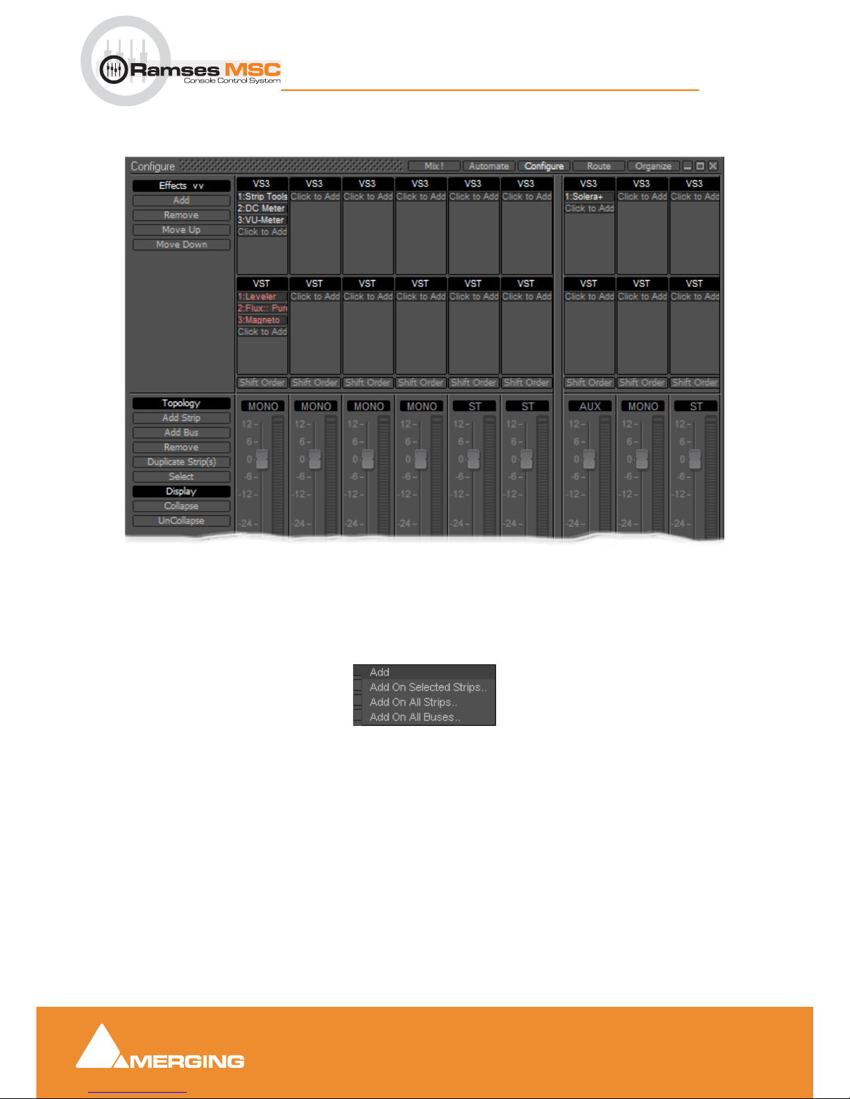
Pyramix Mixer
12 - 98
Ramses MSC reference guide
Pyramix Mixer : Configure Page
Effect Management
Clicking on Effects >> expands the Effects section.
This offers several methods of managing effects on strips and busses.
Configure: Effects Buttons
Add Pops up a sub-menu with options
Add On Selected Strips..
Add On All Strips..
Add On All Buses..
Configure Page - Effects section
Page 99
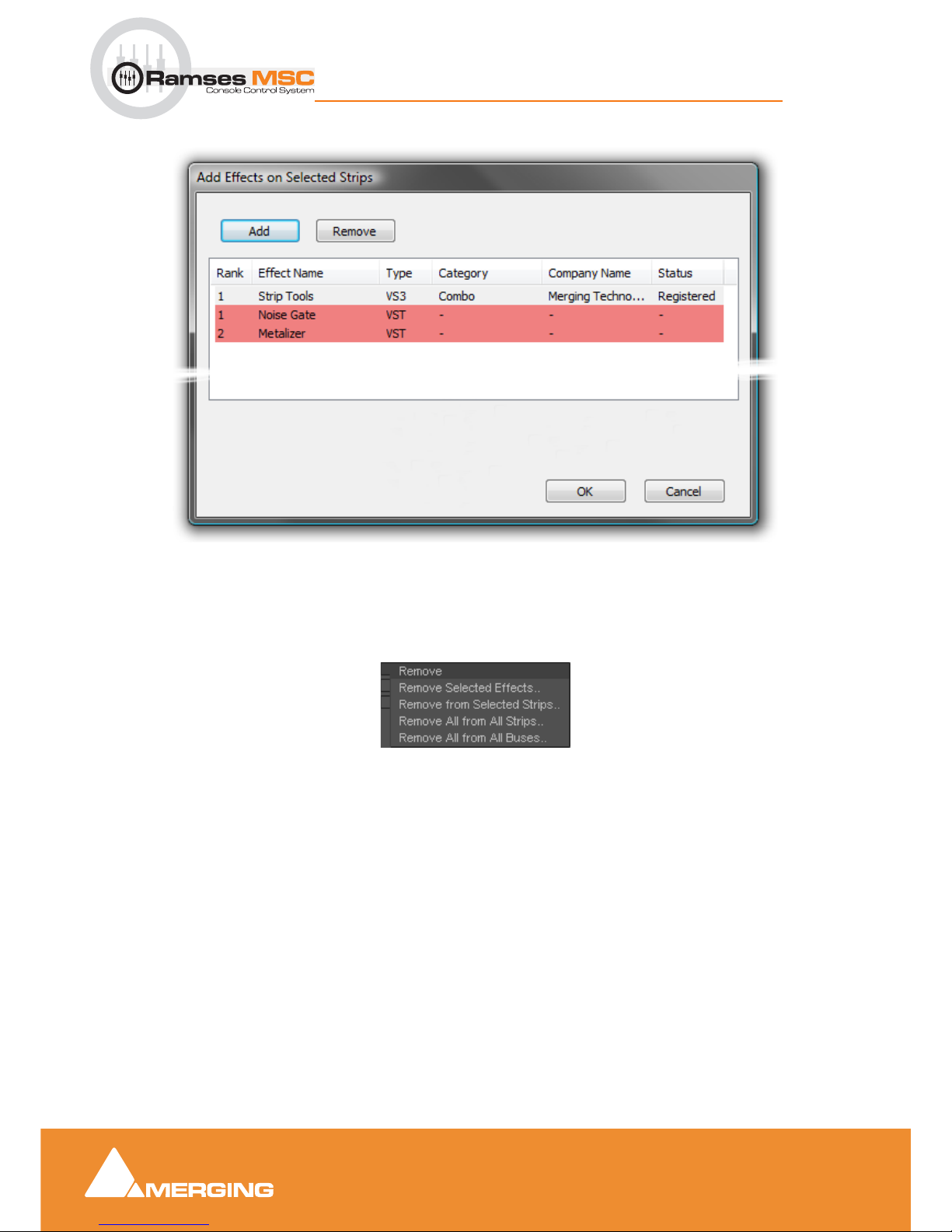
Pyramix Mixer
12 - 99
Ramses MSC reference guide
Pyramix Mixer : Configure Page
Each of these three options opens an Add Effect On XXX dialog, identical apart from the title
Note: That the different types of effect are shown by color. Pale Gray for VS3 and Red for
VST. These colors are also used when effects are shown in containers in the Strips display.
Remove Pops up a sub-menu with options:
Remove Selected Effects..
Remove From Selected Strips..
Remove All From All Strips..
Remove All From All Buses..
Move Up
Moves the selected effect(s) up in the list.
Move Down Moves the selected effect(s) down in the list.
Effects Section Containers
The Effects section of each strip is divided into two container areas by plug-in type, VS3 at the top and VST
below. Clicking on the
Click to Add buttons in each container pops-up a list of available plug-ins in the rel-
evant format sub-grouped by type. E.g. Dynamics, Restoration
etc. Simply select from the list by clicking on
an entry to install the plug-in in the Strip. When a Strip or Bus has many effects, the container expands to
accommodate them.
Shift Order
Add Effects On Selected Strips dialog
Page 100
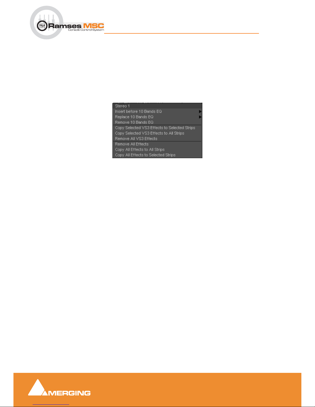
Pyramix Mixer
12 - 100
Ramses MSC reference guide
Pyramix Mixer : Configure Page
You can change the order of the VS3 and VST containers by clicking on the Shift Order buttons below the
containers.
Selecting, Copying and Moving Effects
You can select an installed effect with a left-Click then drag and drop to move or Ctrl + drag and drop to
copy effects of the same type to a Strip or Bus of the same dimensions or change the order of effects within
the effect type container of the strip.
SHIFT + Clicking a second effect with an effect already selected,
selects all effects between the first and last selected.
Ctrl + Click adds to selection.
Right-clicking on an installed plug-in pops-up a context menu, for example:
Insert before (effect clicked on) > drops down a list of effects of the same type that can be inserted before current
the effect.
Replace (effect clicked on) > drops down a list of effects of the same type that can replace the current effect.
Double-Clicking an installed effect does the same thing.
Remove (effect clicked on) Uninstalls the current effect from the Strip or Bus
Copy Selected (Effect type) Effects to selected strips As it says. Target strips can be selected before or after select-
ing the effect(s)
Copy Selected (Effect type) to All Strips As it says.
Remove All (Effect type) Effects Removes all effect of the current type from the Strip.
Remove All Effects Removes all effects of all types from the current Strip.
Copy All Effects to All Strips Copies all the effects installed in the current Strip to all other Strips.
Copy All Effects to Selected Strips Copies all the effects installed in the current Strip to all selected Strips.
External Effects Inserts
External Inserts are added in the same way as VS3 Effects. Click on Click to Add and choose Other >
External Insert
Effect context popup
 Loading...