

Page 1

www.merging.com
www.merging.com
USER MANUAL
Pyramix 4.3
Page 2

No part of this documentation may reproduced in any form whatsoever or be stored in
any data retrieval system without prior written permission of the copyright owners.
This documentation is supplied on an as-is basis. Information contained within this
documentation is subject to change at any time without notice and must not be relied
upon.
All company and product names are ™ or Registered Trademarks ® of their respective
owners. Windows XP, Windows 2000 and Windows NT are trademarks of Microsoft
Corporation.
Merging Technologies makes no warranties express or implied regarding this software,
its quality, performance, merchantability or fitness for a particular purpose. The software is supplied “as is” you, the purchaser, are assuming the entire risk of the results
of using this Merging Technologies software.
In no circumstances will Merging Technologies, its owners, directors, officers, employees or agents be liable to you for any consequential, incidental or indirect loss or damages including loss of time, loss of business, loss of profits, loss of data or similar
resulting from the use of or inability to use the Merging Technologies hardware and or
software or for any defect in the hardware software or documentation.
© Copyright Merging Technologies Inc. 2004. All rights reserved
Merging Technologies
Le Verney 1070 Puidoux Switzerland
Tel: +41 21 946 04 44 • Fax: +41 21 946 04 45
www.merging.com
Page 3

User Manual : Contents
3
User Manual : Contents
Page 4

User Manual : Contents
4
Thank you! 14
Pyramix Versions 15
Pyramix Native 15
Native Playback Channels 16
Pyramix LE 16
Pyramix Virtual Studio Core 16
Introduction 17
Conventions 17
Pyramix Guides 18
Installation Guide 18
Virtual Transport Guide 18
Pyramix Applications Guides 18
Guides for Pyramix Optional Features 18
Pyramix Virtual Studio Overview 19
Pyramix Card and Software Set and Pyramix Turnkey 19
Pyramix Virtual Studio Board I/O 19
Time Code and Video Sync Option 20
System Requirements For Pyramix Virtual Studio 20
Digital Audio Synchronization and TimeCode 22
Installing Pyramix Virtual Studio Hardware 23
Mykerinos Board Installation 23
Multi-board installation 23
Daughter-cards 23
External Audio D/A-A/D Converter Boxes 23
Cabling Pyramix in your System Environment 24
Installing Pyramix Virtual Studio Software 26
Driver Signing 26
Running the Installer 26
Enabling Pyramix Virtual Studio with your Software Key 27
Pyramix User Interface 28
Mouse Modifier Keys 28
Context Menus 28
Keyboard Shortcuts 28
Macros 28
Tutorial Project 28
Project Templates 29
Pyramix Concepts 30
Page 5

User Manual : Contents
5
Project 30
Mixer 30
Compositions 30
Timeline 30
EDL 30
Media Files 30
Master Clips 30
Clips 31
Media Management - Housekeeping 31
Media Drives and Folders 31
Libraries 31
User Libraries 31
Automation in libraries 31
Global Libraries 31
Offline / Reference Libraries 32
Sound Effects / Large Projects and Offline Libraries 32
Project Libraries 33
Library Maintenance 33
Track and Mixer Muting 33
TimeCode Entry 34
Starting Pyramix Virtual Studio 36
Beginning a New Project 37
New Project from scratch 38
Mixer Wizard 41
Getting Audio into Pyramix Virtual Studio 44
Check Sync 44
Pyramix audio file format 45
Recording Audio into a Pyramix Virtual Studio Project 45
Track Record Modes 45
After Recording 45
AutoPunch Mode 46
Importing Audio Files into Pyramix Virtual Studio 47
Practical Media Management and Libraries 49
Clips and Compositions 49
Media Folders 49
Editing 52
Clips and Compositions 52
Page 6

User Manual : Contents
6
Anatomy of a Clip 52
Locking Clips 54
Grouping Clips 54
Gain WIndow 54
Clip and Selection Editing 54
Selections and Region Selections 55
Dragging Clips into a Composition 56
Copy and Paste 56
Auto-Crossfade By Default 58
Clip Fade Commands 58
Editing Modes 59
Splitting Clips and Regions 59
Jog-Wheel Editing 60
Edit Command highlights: 60
Auto Silence Removal 63
The Placement Tool 65
Markers or User Flags 66
Using the Mixer 67
Mixer Components 67
Creating and Configuring Mixers 69
I/O Busses Explained 69
Internal Return Busses 69
Mixer Delay Compensation 69
Input Strips 70
Groups 70
Mixing/Monitoring/Aux Buses 71
Configuring a Blank or Existing Mixer 73
Mixer Configure Mode 74
Adding Strips 74
Mixer I/O Assignments 74
Adding Plug-ins 74
Further Mixer Configuration Options 75
Dithering 76
Channel Direct Outputs 77
Storing and Recalling Mixer Presets 77
Mixer Surround Components 78
Configuration - Program and Project Settings Windows 81
Page 7

User Manual : Contents
7
General Settings 82
General 82
Editing 84
Playback 86
Layout 88
Locations 90
Time Code 91
Jog / Chase 94
Video 98
Keys 99
Machines 100
Controllers 103
Virtual Transport 104
Project Information & Settings 106
Information 106
Record 107
Controllers 111
Mixer Settings 112
General 112
I/O and Sync 114
Mykerinos Daughter Card Settings 116
Level Meter 116
Pyramix Virtual Studio Window Orientation 119
Program Window 119
Project Window 120
Dual Monitors 120
Project Editing Panel 120
Project Management Panel 121
Tracks 122
Adding and Deleting Tracks 122
Track Header Panel 123
Navigation 126
Jog / Shuttle 127
Transport Controls 128
Transport Control Panel 131
Zooming and Panning 131
Scroll Wheel 132
Page 8

User Manual : Contents
8
The Overview 133
Project Management Panel Tabs 134
Overview 134
EDL 134
Document Libraries 135
Media Management 141
Tracks 149
Track Groups 152
Playlists 154
Work Spaces 154
Selection 154
Fade Editor 158
Markers 164
CD 165
Notes 172
Machines 173
Global Libraries 173
Cue Sequencer 173
External Machines 174
9-pin (Sony P2 protocol) 174
Setting up an external machine 174
Virtual Multi-track 175
Digitizing Sessions 177
Manual Digitizing 178
Autoconforming 178
Conforming and Reconforming 180
Importing a CMX EDL 180
CMX EDL Format 182
CMX Autoconform 184
CMX Reconform 184
Source - Destination Editing 188
Concept 188
Setting up a Source - Destination environment 188
Automation 192
Automation Modes 192
Automation Settings 193
Selecting Automation Modes 194
Page 9

User Manual : Contents
9
Master Automation Controls 195
Display and Editing of Automation Data 196
Undo/Redo 198
Editing Automation data 198
Automation in editing and libraries 199
Mixer and Plug-in Snapshots 199
Virtual Transport 201
What is Virtual Transport? 201
Strip and Bus Tools - Plug-ins 202
Eq, Comp/Limiter/Expander 202
Bus Tools 212
Delay Compensation 214
Delay Compensation / Pre-Anticipation 217
Plug-Ins 218
Common Master Section 218
Parametric EQ. 220
10 Bands EQ 221
Three Band Tone Control 221
Dynamics Processing 222
Delay 224
Flanger 225
MS Encoder 226
AnguDion 226
Mastering Peak/Vu Meters 228
Phase-Oscillo 234
Surround Meter 236
DC Meter 237
Modulometer 237
Function Generator 239
Plug-in Automation 240
Effects Snapshots 240
Optional Plug-ins 241
Prosoniq MPEX2 Timestretch and pitch change 241
VST / DirectX support 244
Direct X Plug-ins 244
VST Plug-ins 244
External Effects 245
Page 10

User Manual : Contents
10
Mastering a Composition to CD-R 246
CD Markers 246
Project Processes 247
Dither 247
Mixing Down Projects 247
Exporting Projects to CD Image Files 248
DiscWrite 249
Optical Drives - Important Note: 252
CD Text 252
Burning a CD-R 252
Archiving Projects 254
Consolidating Projects 254
Converting Projects 256
Changing Project Length / Pitch 256
Reconforming a Project 256
Surround Post-Processing Projects 256
Rendering Projects 257
Currently Available Plug-ins 258
Cleaning Up Project media 258
Project Interchange 259
File Interchange with Apple Macintosh 259
AAF 260
Akai DD / DR 262
CD Import 263
CMX EDL 265
OMF 265
ProTools 265
Report Printer 268
Cue Sheet Printer 268
Customizing the User Interface 272
Interface Editor 272
Workspaces 273
Customizing Keyboard Shortcuts 274
User Macros 275
Application Specific Configurations 276
Multitrack Editing 276
LTC sync 276
Page 11

User Manual : Contents
11
Dubbing Mode 277
Virtual Tape Mode 277
Discontinuous TimeCode 280
Metronome / Click Track 281
Menus - Project Menu 283
Menus - Edit menu 286
Menus - View Menu 292
Menus - Clips 296
Menus - Tracks 301
Menus - Cursors and marks 303
Menus - Selection 307
Menus - Fade Editor 309
Menus - Automation 313
Menus - Workspaces 314
Menus - Machines 315
Menus - Macro 320
Menus - Settings 320
Menus - Window 320
Menus - Help 321
Remote Control 322
Control of External Device 322
Control by External Device 322
Hardware Control Surfaces 322
GPI / GPO Support 324
Optimizing Pyramix 326
Use Templates 326
Pyramix File Format .PMF 326
One File Per Track option 326
DSP optimization 326
Troubleshooting 328
Keeping Up To Date 328
Error Messages 328
Multi-channel Audio Files 329
No Sound on Live Inputs 330
Clip Display Problems 331
Relaunch After Improper Exit 332
The I/O Status window 333
Page 12

User Manual : Contents
12
Input sources 333
Debug Menu 333
Appendix I Mouse Modifier Keys 336
Main Editor 336
Overview 338
Notes 338
Media Folder 338
Appendix II I/O Daughter-card Options 339
Appendix III Optional Features 341
Pyramix DSD / SACD 341
Time-code Sync 342
Cue Sequencer 342
Appendix IV 9 - Pin connection 344
PC RS-232 Serial Port to External Sony P2 RS-422 Controller 344
Connecting an RS422 device using a direct cable 344
Appendix V Mykerinos Latencies 346
Index 347
Page 13

www.merging.com
USER MANUAL
User Manual
Page 14

User Manual : Thank you!
User Manual
14
Thank you!
Congratulations on your purchase of Pyramix Virtual Studio. More than just a product, this is a gateway to the future of sound recording, editing, mixing and mastering. You have joined a worldwide community of users who have already discovered the Pyramix advantage.
Note: IMPORTANT! - The first thing you need to do is register your software to
acquire your Pyramix key(s) and to be included in our user support list.
Please also subscribe to the User Forum at:
http://www.merging.com/forum/
Page 15

User Manual : Pyramix Versions
User Manual
15
Pyramix Versions
There are now several versions of Pyramix. Pyramix Native, Pyramix Native Media Bundle, Pyramix LE
and Pyramix Virtual Studio. Numerous options and option packs are also available. This manual covers
all versions of Pyramix and many optional functionalities and features.
Note: Depending on the version and options purchased, some of the functions and
features detailed in this manual may, or may not, be available in your version of Pyramix, or may vary in capacity.
Pyramix Native
Pyramix Native offers 100% compatibility with the main Pyramix Virtual Studio (VS) system. Both the
Pyramix Native and the Pyramix VS can be connected on the same standard Ethernet network and
directly interchange audio and video media, or a complete Pyramix project between them.The Native
software is USB dongle protected and runs on Windows 2000 or Windows XP desk-top or lap-top computers. It does have restrictions compared to the main Pyr amix Virtual Studio capabilities as you would
expect but the Native software maintains all the real-time editing capabilities expected of a professional
system.
Pyramix native includes…
• Tone Control,
• 4 Band Parametric EQ
• Dynamics processor
• 2 Channel Record Inputs
• 2 Channel Playback Outputs
• 4 Audible Internal Editing Tracks
• Real-time Editing
• Source/Destination Editing
• Track Grouping
• Up to 48kHz sample rate
• CD Import
• Direct-X and VST capability
• Supports, PMF, WAV, BWF, AIFF, SD2,
OMF and CD Image audio formats as
standard.
Pyramix native media Bundle Includes Native
configuration PLUS…
• 8 Audible Internal Editing Tracks
• Pyramix Core (inc. including VT Server)
• 10 band Graphic Equalizer
• Strip Tools, Bus Tools
• Delay, Echo
• Generator (Sinus, Pulse, DC)
• Flanger
• Mastering Peak/Vu meters
• Phase Correlator and Audio
• Vectorscope
• Angudion
• Nagra Modulometer
• CD-R Mastering
• Disk Write Software
• Virtual Transport Server
• Virtual Transport MIDI Sync Client
• DS Video Player
Page 16

User Manual : Pyramix Versions
User Manual
16
Native Playback Channels
In the standard Native configuration the Mixing Console is limited to 4 playback channels. In the Native
Media Bundle this is expanded to 8 playback channels. These channels are the first 4/8 strips of the
mixer, regardless of how the mixer is configured.
Both Native and Native Media Bundle configurations can have any number of tracks and can connect
any of them to any of the first 4/8 strips of the mixer.
The Mixing console allows only 2 live inputs but they can be patched to any of the strips of the console.
The Mixing console can have any number of strips, but only the first 4/8 can playback from Pyramix
tracks. All other strips can be used for live or internal aux busses return.
Both configurations can load projects that come from a Pyramix Virtual Studio system (Mykerinos
based) without any track limitations. Once loaded it shows all original connections on the track headers.
It will create the same mixer as used in the main Pyramix system, but only the first 4/8 strips will actually
playback audio.
Pyramix LE
Pyramix LE, currently available as a free of charge item, bundled with Mykerinos hardware, includes 16
tracks, Tone Control, 4 Band Parametric EQ and Dynamics processor effects.
Pyramix Virtual Studio Core
Pyramix Virtual Studio Core includes Pyramix LE features plus:
• Unlimited number of Tracks
• 10 band Graphic Equalizer
• Strip Tools, Bus Tools
• Delay, Echo
• Generator (Sinus, Pulse, DC)
• Flanger
• Mastering Peak/Vu meters
• Phase correlator and Audio Vectorscope
• Angudion
• Nagra Modulometer
• Virtual Transport Server (VT Clients require separate ordering)
• Virtual Transport DS Video Player client
Page 17

User Manual : Introduction
User Manual
17
Introduction
Assumptions
This User Manual and the other Pyramix guides assume you are thoroughly familiar with PCs and Win-
dows terms and concepts. If the PC is new, please ensure the machine is working correctly before
attempting to install Pyramix Virtual Studio.
Conventions
Conventions used in this manual:
Names found on Pyramix screens and menus are shown in bold. E.g. Information & Settings
Menu and sub-menu selections are shown like this:
View > Tracks > Show all Tracks
Which means:
Go to the View pull-down menu, mouse down to the Tracks sub-menu and choose Show all Tracks.
Where a dialog box has several Pages, Tabs are used to ‘turn’ the pages. Ta b page selection is shown
thus:
Project > Information & Settings : Record
Which means:
Go to the Project pull down menu, choose Information & Settings then click on the Record Ta b.
Page 18

User Manual : Pyramix Guides
User Manual
18
Pyramix Guides
User Manual
This manual is intended to enable new users to achieve good results quickly. It also aims to introduce
existing Pyramix users to the new features in Pyramix 4.3.
Other Pyramix Guides
The other guides listed here are installed along with the Pyramix software and may be freely downloaded from the Merging Technologies website.
http://www.merging.com
Installation Guide
An expanded version of the chapter: Installing Pyramix Virtual Studio Hardware on page 23
Virtual Transport Guide
This is the reference guide for Virtual Transport.
Pyramix Applications Guides
These guides aim to be a useful resource for Pyramix users. They contain set-up examples and practical hints and tips for using Pyramix for specific applications such as;
Music Recording
Music editing
Mastering
SACD Production Guide
Radio Production
Radio Broadcasting
Theatre Playout
Sound for Picture
Guides for Pyramix Optional Features
Documentation for optional features is provided in PDF format. These are installed with the Pyramix
software or may be freely downloaded from:
http://www.merging.com
Page 19

User Manual : Pyramix Virtual Studio Overview
User Manual
19
Pyramix Virtual Studio Overview
VERY IMPORTANT!
We strongly recommend you consult the other Pyramix guides, and the Applica-
tions Guide for a more complete understanding of all the features and functions
of Pyramix.
HOWEVER,
recognizing that most people do not read manuals until they have to, this ver-
sion will enable you to achieve (almost) instant gratification! This manual will
introduce you to Pyramix Virtual Studio Version 4.3 and lead you through a simple set-up, recording and importing audio, simple editing, mixing, adding
effects, and CD recording.
Pyramix Virtual Studio is a powerful and flexible Digital Audio Workstation (DAW) integrating hard
disk recording and editing, digital audio mixing, effects processing, machine control, video, and CD-R
mastering.
The Pyramix software runs on the Merging Technologies Mykerinos hardware platform. Each Myk-
erinos board is capable of up to 128 channels of 24-bit digital audio, 64 recording and 64 playback.
External access to these 128 channels is determined by your choice of physical inputs and outputs to
the Mykerinos board.
Pyramix Card and Software Set and Pyramix Turnkey
Your Pyramix Virtual Studio will have been supplied in one of two forms:
Pyramix Card and Software Set or Pyramix Turnkey.
Pyramix Turnkey systems are complete, ready to go, rack-mounted PCs with the Pyramix Card and
Software Set already installed and properly configured at the Merging Technologies factory. As such, no
user installation or configuration is needed. You can launch and run the Pyramix software immediately.
Pyramix Card and Software Set consists of the Mykerinos hardware and the Pyramix software
ONLY. You must provide an appropriate computer platform and software environment in which to install
the board and software, and install these yourself. Guidelines for an appropriate Pyramix system environment can be found in the following section.
Future Expansion is of course, possible, whether you start with Turnkey or Card and Software Set.
Pyramix Virtual Studio Board I/O
Audio I/O Options
Mykerinos is a modular board which can have any one of several optional audio I/O daughter cards
attached. When ordering Pyramix Virtual Studio from Merging Technologies or one of its distributors, be
sure to specify the daughter card appropriate to your specific needs. (Please see Appendix II I/O
Daughter-card Options on page 339)
Page 20

User Manual : Pyramix Virtual Studio Overview
User Manual
20
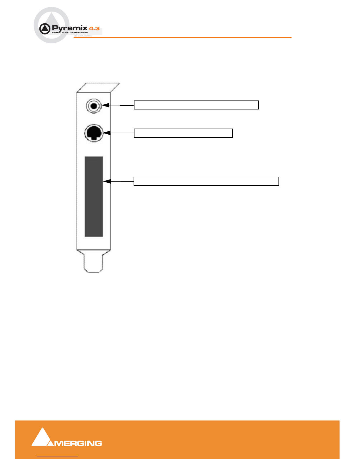
On-board Analog Audio I/O
Regardless of which I/O daughter card is chosen, you can simultaneously use the 3.5mm stereo miniphone jack on the Mykerinos board as an unbalanced, analog stereo audio monitor output for all
projects up to 384 kHz, with levels programmable from within the Pyramix software. Sources at sample
rates higher than 96 kHz are automatically Sample Rate Converted to 96 kHz, 24 bit. This stereo minijack connection may be connected to headphones or to a line level audio monitor input.
Time Code and Video Sync Option
The Pyramix Synchronization option provides SMPTE / EBU LTC and VITC time code in/out, video
sync in/out and word clock sync. A multi-pin circular mini-DIN connector, on the back plate of the Mykerinos board carries all the system synchronization, time code and video sync signals. An optional
break-out cable is provided for connections to time code, sync and video I/O. The Synchronization
option allows Pyramix to be configured as a master or slave lock to external time code, video or word
clock. It also enables VITC and/or a visible time code burn-in window (BITC) to be added to video output/throughput.
System Requirements For Pyramix Virtual Studio
Computer
• PC with Intel Pentium PIII 800 MHz or higher, minimum 256 MB RAM.
• PCI 2.1 compliant card slot(s) in which to install the Mykerinos board(s).
• Windows XP, Windows 2000 or Windows NT Workstation (v4.0 SP6 or higher OS
• Graphics Adapter with a minimum resolution of 1024x768 (Dual Head with resolution of 1280 x
1024 recommended).
• Sufficient HD space and speed for your audio media files. The speed and amount of disk space
required depends on sample rate, bit depth, number of tracks and length of program material. A fast
(10k rpm or better 15k rpm) SCSI drive (e.g. Seagate Cheetah) or a SCSI RAID array is recommended for larger multi-track projects, high sample rate and DSD work. Low cost IDE drives are
fine for smaller projects of up to 24 channels.
• We recommend disks should be formatted as NTFS volumes.
Hard Disk Space Requirements
A complete software installation will require around 50MB of disk space for the Pyramix software itself
and approximately 10MB of disk space for the Virtual Transport.
In addition, you will need hard disk storage for any captured audio media files. As a rule of thumb, one
Gigabyte of disk storage equals:
• 185 track minutes at 44.1 kHz 16 bits
• 125 track minutes at 44.1 kHz 24 bits
• 170 track minutes at 48 kHz 16 bits
• 115 track minutes at 48 kHz 24 bits
• 55 track minutes at 96 kHz 24 bits
For continuous multi-track recording applications, divide total available mono track time by the number
of tracks you will be using.
Page 21

User Manual : Pyramix Virtual Studio Overview
User Manual
21
Please note that these are very rough estimates, and should be used only as a general indication of
storage requirements.
Operating System
Windows XP, Windows 2000 or Windows NT Workstation (v4.0 SP6 or higher) installed (never attempt
to install Pyramix on NT Server). Windows XP is preferred.
Drivers
Regularly acquiring and installing the latest Drivers/Firmware/Bios or Operating System available for
equipment such as: Graphic Cards, CD/DVD writers, Network Adapters, Motherboards, (but exercise
especial caution), external drives, RAID controllers and other third party hardware add-ons, will ensure
that your system will always perform as efficiently as possible. Always accept any ‘rollback’ options, just
in case the driver updates have unforeseen consequences.
Drivers should have the Microsoft digital signature, where available. However, the latest drivers will
often not be signed. In these cases use the latest driver which is known to work or otherwise certified.
This may require a little on-line research.
Graphics cards and optical drives, in particular, benefit from the most recent stable driver updates.
Keeping Windows (and DirectX) up to date with latest service packs is also, in general, a positive move
towards maintaining a healthy system.
Note: These operations are not required for Mykerinos and Daughter cards simply
because the latest firmware for your hardware (if any) is automatically installed by the
most recent Pyramix installer.
Power Management
N.B. As with all Digital Audio Workstations and Non-Linear Editors, we recommend setting the PC to an
Always On Power management scheme. (Start > Settings > Control Panel double click Power
Options. Choose Always On from the Power Schemes drop down list.) This allows the monitor to be
turned off by the system but disables hard-disk turn off and Standby.
Note: The Mykerinos card is not designed to support Standby modes.
Other Applications
Like all Digital Audio Workstations, Pyramix works best when there are no other unnecessary applications or services running.
Video and Pyramix on one PC
To ensure a very smooth system (especially for seeking) playing video with Pyramix on the same computer, we recommend a Dual Processor PC, a dedicated hard drive for the video and Windows XP
Page 22

User Manual : Digital Audio Synchronization and TimeCode
User Manual
22
Digital Audio Synchronization and TimeCode
THERE MUST BE ONLY ONE SOURCE OF SYNC FOR AUDIO AND TIME-CODE
Digital audio relies on extremely accurate timing. In any digital audio system there can only be one
source of sync at one time. This is particularly important when planning multi-machine systems. If timecode is not locked to the same sync source as the digital audio then either the audio will work properly,
or the time-code. But NOT BOTH AT THE SAME TIME.
Ideally, in any system with more than one device, there will also be an independent source of sync. E.g.
a word-clock generator with multiple outputs. Each device is fed by a single output and configured to
use this source as its sync reference.
Example:
A location digital recorder records at a nominal 44.1kHz sampling rate generated by its internal crystal
oscillator and also records time-code derived from the same oscillator. Although the machine may be
running slightly slow or fast the digital audio and time-code will vary by exactly the same percentage.
When this location recording is played back on a machine locked to a stable sync source, digital audio
will play at the same rate as the workstation and the time-code will be correct.
Consider an alternative scenario:
A digital multi-track is used as a location recorder, synced to its internal oscillator. Time-code is
recorded on an audio track sourced from, say, a camcorder. When the resulting tape is played back on
a machine locked to a stable sync source, the audio will be at the correct rate but the time-code will
‘drift’ in relation to it. The amount of this error is known as ‘DELTA’. Delta is simply the result of the following formula: Internal TC minus External TC minus Offset = Delta. Where such a recording exists and
it is imperative the time-code on tape is the master reference there are several solutions. The preferred
options are:
Play back the tape with the machine chase-synchronized to the recorded time-code. Since the digital
audio is not locked to the time-code the sample rate will drift. If recorded directly, this would result in
missed or duplicated samples. I.e. unpleasant audible artefacts. Therefore, in order to record the audio
in Pyramix it must go via a digital audio synchronizer/sample rate converter synchronized to the master
word-clock source. This will then present Pyramix with digital audio at the correct rate.
Alternatively, the audio could be converted to analogue then fed into Pyramix via an analogue to digital
converter.
Page 23

User Manual : Installing Pyramix Virtual Studio Hardware
User Manual
23
Installing Pyramix Virtual Studio Hardware
Mykerinos Board Installation
The Merging Technologies Mykerinos board can be installed in any free PCI slot in your PC. In general,
it is best NOT to install the board in the PCI slot adjacent to an AGP graphics adapter; and in a PCI slot
which may be physically shared with an ISA slot.
Please consult the merging.com website for current compatibility information.
Make absolutely certain the PC power is OFF before installing the board!
With most of the current generation motherboards this means either the mains switch on the power supply or the power outlet switch. Where no switch is provided, either on the PC or the supply socket, then
the PC should be unplugged.
Always observe proper static precautions when handling any PC boards! Use a static strap, and/or be
sure to firmly ground yourself to the computer power supply, chassis or if the PC is unplugged, to a
known good earth before handling and installing the Mykerinos board.
Some PCs have batteries, cables, jumpers, etc. which could prevent proper board seating in one or
more slots. Make certain the board is firmly and fully seated before switching on.
Multi-board installation
Multiple boards must be installed in adjacent slots. To enable multi-board operation, all Mykerinos cards
in the PC have to be connected together using a special HDTDM ribbon cable. This cable has to be
plugged into the multi-pin connectors located on the top edge of the I/O daughter cards. Please contact
your Merging Technologies dealer for information on how to order this HDTDM ribbon cable.
HDTDM
The HDTDM cable has the following functions in a multiple Mykerinos board installation:
a) synchronization (to 1/512th of an audio sample accuracy) This enables Pyramix to "see" a single system comprised of a large pool of DSP power and I/O resources spread over separate cards.
b) transfers all audio signals (Live Inputs, Internal Send/Return Busses, Mix busses, Aux busses, Live
Outputs, etc. between all the Mykerinos I/O daughter-cards which comprise the multi-board system.
Daughter-cards
Please see Appendix II I/O Daughter-card Options on page 339 for a description of the available
daughter-cards.
External Audio D/A-A/D Converter Boxes
Most of the I/O options for the Mykerinos board are digital. Pyramix will often be used with external
audio D/A (for playback) and A/D (for recording) converters. Many such converters are available from
Merging Technologies as options: for example, the Merging Technologies Dua II and Sphynx boxes.
Contact Merging Technologies Sales for more information.
Capabilities of third party D/A - A/D converter boxes are widely variable. Please check with the manufacturer to ascertain which sample rates, word lengths and number of I/O channels are supported. You
will need this information later to appropriately configure the Pyramix software.
Page 24
User Manual : Cabling Pyramix in your System Environment
User Manual
24
Cabling Pyramix in your System Environment
Please read this in conjunction with the guide or guides for your specific interface daughter-cards and
external interfaces/converters.
Due to the number of possible I/O options and the variety of user environments it is impossible to cover
all the variations of cable connections to and from Pyramix.
However, here are some general rules and examples:
Audio Connections
Many users will have A/D Converters for feeding analog audio sources into Pyramix, and D/A Converters for playing analog audio out of Pyramix. In this case, connect your analog audio sources to the A/D
Converter analog audio inputs, and the A/D digital audio output(s) to the Mykerinos digital audio
input(s). Similarly, connect the Mykerinos digital audio output(s) to your D/A Converter digital audio
input(s), and the D/A Converter analog audio outputs to your studio monitors or recorders. It may be
also be useful to connect the stereo mini-phone output on the Mykerinos card to either stereo headphones or a stereo monitor console input. The source for this jack can be configured inside the Pyramix
software.
3.5mm Mini-Phone Jack for analog monitor output
8-pin Mini-DIN for sync breakout cable
Area where I/O Daughter Card output connectors appear
Mykerinos Backplate
Page 25

User Manual : Cabling Pyramix in your System Environment
User Manual
25
Sync, Video and Time Code Connections
In any digital audio system, it is VERY IMPORTANT all interconnected units are locked to the same
sync reference. A digital audio signal itself can sometimes be used as the master sync source, but a
high stability video or wordclock signal is usually preferable.
The Mykerinos board can be configured inside the Pyramix software to act as either a sync master, or to
slave to a variety of incoming signals.
Decide which device in your system will provide the master sync reference, then ensure that all other
digital audio devices in your system take their synchronization from it. This will require routing appropriate cables --whether digital audio, video or wordclock cables-- to the various other devices and may
also involve a separate sync reference generator and or distribution amplifiers.
If Pyramix is configured as the master (Internal sync), other digital audio devices will probably be able to
lock to the digital audio output from Pyramix. However, Pyramix can also be configured to output a
wordclock signal at the Video output BNC connector (Pyramix Synchronization option required).
If Pyramix is configured as a slave to an external device, Various synchronization signals can be
accepted.
• To lock to incoming digital audio, connect an appropriate digital audio signal to a Pyramix digital
audio input.
• To lock to incoming video, connect an appropriate video signal to the Pyramix Video Reference
input (Pyramix Synchronization option required).
• To lock to incoming wordclock, connect an appropriate master wordclock signal to the Pyramix
Video 2 Input (Pyramix Synchronization option required).
• To set the termination jumpers provided on the Mykerinos board, please see the Mykerinos User
Guide.
Pyramix can either output or lock to incoming SMPTE / EBU time code.
• If a master LTC time code output from Pyramix is needed, cable the Pyramix LTC time code out
RCA jack or XLR to any other devices slaving to this output (Pyramix Synchronization option
required). Pyramix always generates time code when playing.
• To lock Pyramix to an incoming LTC time code signal, cable the LTC time code output from the time
code source to the Pyramix LTC input RCA jack or XLR (Pyramix Synchronization option required).
Pyramix can accept and generate VITC in standard PAL/NTSC formats. It can also provide BITC (Burnt
In Time-Code) on its video outputs.
MIDI Connections
To use Pyramix MIDI functionality with external equipment, you will require a MIDI interface. Many current motherboards include an on-board MIDI interface. If yours does not, it is a simple matter to add
one. This can be either an internal PCI card or an external unit connected via a USB port or an RS232
serial COM port.
Page 26
User Manual : Installing Pyramix Virtual Studio Software
User Manual
26
Installing Pyramix Virtual Studio Software
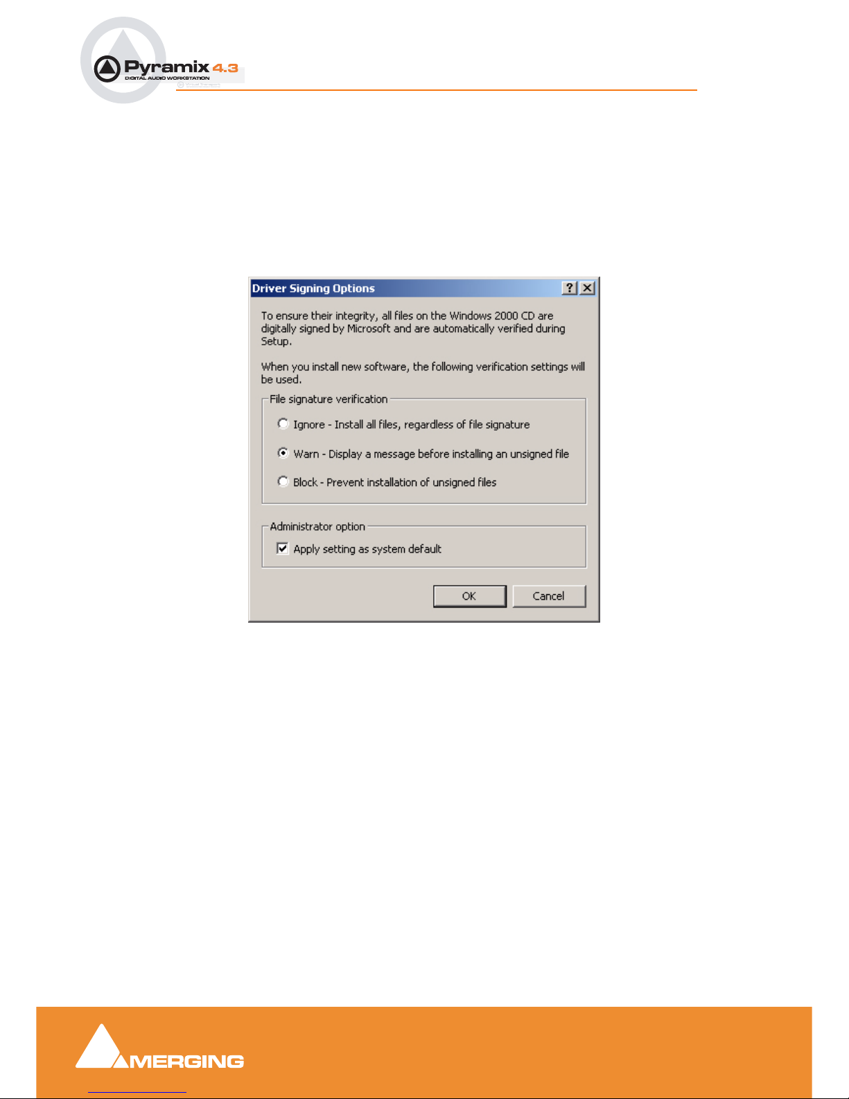
Driver Signing
Important! Before attempting to install the Pyramix Virtual Studio software please check the
following setting:
Start > Settings > Control Panel > System : Hardware
Click on the Hardware Tab, then click on Driver Signing. The Driver Signing Options dialog opens:
Make sure the middle option Warn is selected.
Running the Installer
Pyramix Virtual Studio and Virtual Transport software is provided on a CD-ROM. You may also
receive software updates as a download from our ftp site. In either case, install the Pyramix and Virtual
Transport software by running the Virtual Transport and Pyramix Virtual Studio Installer programs.
Choose the default location to install the software unless you have good reason to do otherwise. You
will also be asked to a create folders for your media files and for CD Images (these can be changed
later). If you receive any error messages regarding the Microsoft Digital Signature, ignore these and
continue on with the installation by clicking ‘Yes’.
Important! After installation, please reboot the PC before attempting to launch Pyramix Virtual
Studio. Then open the VS3 control panel application (Start > Programs > Pyramix > VS3
control panel). The default Tab page is Configuration. Select 8 in the Internal Return Bus-
ses drop down menu box then click on the Autorouting button followed by the OK button.
When the VS3 panel, Do you want to save routing? dialogue box appears, click on OK to
close the VS3 control panel.
Double-click on the Pyramix Virtual Studio desktop icon to launch Pyramix.
Driver Signing Options dialog
Page 27

User Manual : Installing Pyramix Virtual Studio Software
User Manual
27
Enabling Pyramix Virtual Studio with your Software Key
Pyramix Virtual Studio is protected by a special software Key. Once you have registered your software
you will be provided with this Key or Keys (depending on the chosen options).
Entering your Key(s)
After the Pyramix installation process you will be prompted to enter your Authorization Key. If you click
Yes the MT Security Settings dialog will be launched automatically, allowing the Key or Keys to be
entered immediately. If you choose not to enter your Key at this point you can do so later by choosing
one of the following procedures:
1. Double-click the file YourPersonalKeyXXXXX.mtk. This is attached to the email containing your
Key(s).
2. Open the MT Security Settings Control Panel
(Windows Task Bar Start > Control Panel > MT Security Settings),
click the Import Key button and browse for your Key file called
YourPersonalKeyXXXXX.mtk
3. Open the MT Security Settings Control Panel (as above), in the Registration section select the
board number corresponding to the serial number for your Keys or HASP Key for a dongle, click the
Enter Key button and type your User Name, Company Name and Key then click OK. Repeat this
step for each Keys listed in the email.
Changing or re-entering a Key
Should you need to subsequently change or re-enter a Key, follow the appropriate option above.
The key system is "smart". Only one key or set of keys is required regardless of the number of boards in
a system. Any card can hold this key set as the authorization is processed based on a "Logical OR" of
all keys present on any and all Mykerinos boards. Of course this Logical OR will only process keys with
identical User Name and Company Name to the one entered in the key enabling dialog box.
Page 28

User Manual : Pyramix User Interface
User Manual
28
Pyramix User Interface
The Pyramix user interface has evolved into an extremely powerful tool for manipulating audio. Commands and functions can be accessed from pull-down menus, pop-up menus, Tab windows and keyboard shortcuts.
There are generally several ways of accessing any given function in Pyramix. This helps users to work
in the way they find most comfortable for the type of projects they are undertaking. It also means ‘Power
Users’ can develop highly efficient operating procedures.
It is perfectly possible to casually use Pyramix without discovering all of the many possibilities on offer.
However, by looking deeper, a far more rewarding experience awaits.
Mouse Modifier Keys
The range of possible actions resulting from a mouse click are massively extended by the use of Keyboard Modifiers. These greatly aid productivity and are well worth learning. Please see: Appendix I
Mouse Modifier Keys on page 336
Context Menus
Right clicking over objects on screen such as clips, mixer strips and controls and track headers pops up
menus with commands and options relevant to the object.
Keyboard Shortcuts
In particular we would encourage users to use keyboard shortcuts and preferably the standard Pyramix
layout. Keyboard shortcuts can be fully customized and users of other workstations will discover we
have also provided familiar keyboard layouts to help them on their learning curve.
Macros
The Macro is another powerful feature of Pyramix. Macros are sequences of commands which can be
invoked by a single key or combination. Some macros are conditional. I.e their precise action depends
on variables in the project. A considerable library of pre-programmed macros is provided together with
an editor which enables users to construct their own macros.
Tutorial Project
An introductory tutorial project is provided on the Pyramix software CD-ROM. If you are new to Pyramix,
please work through the tutorial in conjunction with this manual. Together, they are a comparatively
painless introduction to many of the concepts and terms used in Pyramix.
Page 29
User Manual : Project Templates
User Manual
29
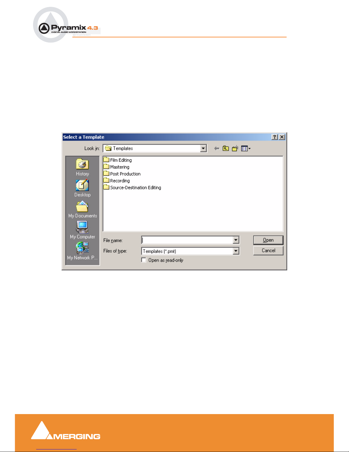
Project Templates
Pyramix provides the user with a number of Tem plates for various applications. A Template is a complete Pyramix Project, without any associated audio, specially configured to suit a particular type of
activity. Apart from configuring the appearance of Pyramix, the track layout and mixer design, templates
also include important optimizations to suit the activity.
Please see: Optimizing Pyramix on page 326
These templates also offer a good starting point for creating your own customized templates. To begin a
new project using a template choose Project > New from Template which opens the Select a Tem-
plate file browser.
When a template is opened a dialog box appears requesting the user to choose a Media Folder for the
new project. Unless the project is saved using the Save As option, the first time it is saved the Save As
dialog will appear.
Further Templates will be added as they are developed.
To save a new Template choose File > Save as Template, name and save.
Select a Template dialog
Page 30

User Manual : Pyramix Concepts
User Manual
30
Pyramix Concepts
Project
A Project is the top level of organization. Projects are saved with the file extension .PMT. A Project
controls and keeps track of all the various elements you are assembling at a given time. A Project
always contains a Mixer and a Composition, viewed on the Timeline, or as an Edit Decision List
(EDL), plus Libraries containing Master Clips, Compositions, Mixer settings, and Fade settings.
Mixer
The Mixer, is the nexus of the Virtual Studio. The Mixer routes all audio into and out of a Pyramix
Project. It also determines audio sample rates and synchronization. The user configures the Mixer as
appropriate, for the number and type of inputs strips and output busses needed for a Project. Without a
properly configured Mixer, no audio can be recorded, mixed, or monitored.
Compositions
A Composition is any number of clips complete with edits and fades, level settings etc. placed on a
track or tracks in a time relation to each other and to the Timeline.
Timeline
The Timeline shows a graphic representation of the current Composition. and its location in relation to
the Playhead Cursor, In and Out Marker Cursors and various other Markers. All editing is done in the
Timeline, EDL or Fade Editor windows.
EDL
The EDL (Edit Decision List), is a textual and numeric representation of the same information shown
in the Timeline and Fade Editor. Changes made here are reflected in the Timeline and vice-versa.
Media Files
These are actual audio data files which can only be seen at the Windows level, e.g. in Windows
Explorer. In Pyramix, they are represented by Master Clips which reference the raw data files.
Master Clips
The concept of Master Clips is one of the keys to the power of Pyramix. An individual Master Clip is a
set of pointers that reference one or more Media Files.
Note that a single Master Clip references all Media Files in a multi-channel audio recording. E.g. a stereo recording can have one or two Media Files, (depending on whether there is a check in the One file
per track box in the Media Option section of the record page of the Project Information and Settings
dialog box.) (Project > Project Information and Settings - Record Tab).
When One file per track is checked, one invisible Media File is generated for each channel of a
recording but only one Master Clip. So.a stereo Master Clip references two invisible Media Files and
a Multi-channel Master Clip references as many invisible Media Files as there are channels in the
recording. check box ‘One file per track’), but will only generate one Master Clip.
A Master Clip can be mono, stereo, four channels, six channels, 24 channels, in fact there is no limit to
the number of channels that can be contained within a Master Clip. When a Master Clip is placed into
a Composition there is the option to place it where it was originally recorded.
Page 31

User Manual : Pyramix Concepts
User Manual
31
Master Clips also contain attributes which identify parameters such as a File name, time code stamp
and other information.
Clips
The individual clips shown on the Timeline contain pointers to Master Clips which in turn point to
audio Media Files.
Media Management - Housekeeping
The Windows hierarchical filing system can easily become confusing and cluttered. Complex audio
projects generate thousands of more or less enigmatically named files. Keeping track of all the files
used in a project can become a nightmare even if the user is meticulous.
Pyramix uses the concepts of Media Drives/Folders and libraries to reduce the clutter and provides
management tools specifically designed for audio. This Media Management helps users to work in a
structured and simple manner whilst keeping track of all the project components.
Media Drives and Folders
Media Drives or Media Folders are Windows folders which contain Media Files. Pyramix needs to
specifically mount these Media Drives in order to access the Media Files contained therein. Once
mounted, suitable files are shown as Master Clips.
Provided the sampling rate is the same as the current project, these can be dragged and dropped or
copied and pasted directly into the Timeline or into a User library from the Media Management Window.
Libraries
Pyramix uses libraries to help make project organization tidier. Libraries are used to organize project
material into logical groupings. However, Libraries are not the same as Windows directories or folders:
they are only meaningful within the Pyramix environment. A Library is a database, containing a collec-
tion of pointers to different kinds of media objects.
User Libraries
User Libraries can contain Master Clips, Compositions, Mixer Snapshots, Plug-in Snapshots,
Fades Settings, etc…. Each Project can have an unlimited number of User Libraries open, each with
an unlimited number and mixture of contents.
N.B. In Pyramix User Libraries, there is no practical distinction between a section of a Composition
(Region) and a complete Composition. Either can be added to a User Library or to an existing Com-
position. This is an extremely powerful feature. A single clip copied to a User Library from the Time-
line appears there as a Composition.
Automation in libraries
If the menu item Edit > Enable Automation Cut/Copy/Paste is enabled then any operation on clips
(Cut/Copy/Paste, Auto-Ripple, etc…) brings all automation data with it
If you drag a clip(s) to a library, all automation over that clip(s) is copied/pasted as well.
Global Libraries
Project Libraries are kept with the Project, Global Libraries are available to all projects and users of
the system. This can be helpful for sound effects or where several users need access to the same
source material to produce different end products.
Page 32

User Manual : Pyramix Concepts
User Manual
32
Offline / Reference Libraries
Offline or Reference Libraries are standard Pyramix Libraries and may be searched or filtered in the
same manner as others.
Offline libraries can be created in the Media Management Tab Window by selecting
Drive > Create Offline/Reference Library.
The new library references all currently mounted media according to the choice made under
Original Media
Only selected Media Drives/Folders
or
All mounted Media folders
Offline Library
The new library can contain references to either all media present in the location(s) chosen in Original
Media:
Add all Media
Or there is the option of filtering out media already present in other libraries by selecting:
Filter Media already present in other libraries
Sound Effects / Large Projects and Offline Libraries
When used in the following manner Offline Libraries provide an extremely powerful organizational tool
for managing very large project libraries and, for example, sound effects libraries.
Mount The Media
In the Media Management Tab Window, Mount all folders or disks containing your audio files (as ripped
with LibraryLoader, mTools or any other source). We strongly suggest these files be in either PMF or
BWF (Broadcast Wave Format) as they both have a long description field, a unique identifier and a
timestamp.
Note: There may well be Copyright implications when working with ripped files. Please
ensure you comply with any restrictions on copying other people’s material.
Create Offline/Reference Library dialog
Page 33

User Manual : Pyramix Concepts
User Manual
33
Create An Initial Library
Select the Media Management Tab Window Menu item Drive > Create Offline/Reference Library
and choose All mounted Media folders and Add all Media. This will create an initial library referencing all your audio files. All the media files / disks may then be unmounted.
The library can now be re-organized, folders created, items duplicated etc. etc.
You can make searches (queries) or apply filters to your Offline / Reference library(ies) and, if Project >
Auto-mount Media is checked, each time an item is dragged onto the Timeline the appropriate audio
file will automatically mount. Or this can be done this manually by calling Project > Mount Referenced
Media.
Updating Libraries - Orphaned Entries
If the original audio files are moved or reorganized, just mount all the folders once again, load all your
libraries and call the Library menu command Update Referenced Media Paths.
Updating Libraries - Adding new files
If new audio files are added to your media disk(s), simply mount these folders, load all your libraries and
proceed as in “Create An Initial Library” above, but select the option, Filter Media already present
in other libraries. This will create a new library containing only references to the freshly added audio
files. These new items can then be copied/moved to any (or many) already existing Offline library(ies).
Project Libraries
When a new Project is created two Project Libraries are also created.
Composition Library
Each Project has a unique, read-only Composition Library. This contains short-cuts to every Master
Clip placed on the Timeline (present in the EDL) in the current Project. Note that the Composition
Library may be empty, I.e. nothing is placed on the Timeline but the user library(s) may contain Master
Clips and Compositions which all form part of the Project.
Default Library
Each new Project also creates an empty User Library named ‘Default Library’. This is provided to aid
housekeeping and is kept with the project.
Library Maintenance
If media is moved or the path to it is changed (E.g. by copy, backup or moving folders etc.) Libraries referencing the ‘orphaned’ media can have their paths updated by simply mounting all the media folders
involved and selecting Drive > Update Media Paths in the Global Libraries tab window
Track and Mixer Muting
There is a subtle difference between muting a Track Output (with the button in the Track Header)
and muting the same signal in it’s associated mixer input strip. Muting a track stops disk access for the
track (There is a delay before the sound stops while the replay buffer is emptied). Muting a mixer strip
doesn't affect disk access but simply mutes the strip (Therefore muting is immediate). Muting track outputs enables multi-track recordings with many tracks (E.g. 48 track music recordings) to be edited on
hardware which cannot support this number of tracks. (E.g. a laptop) Providing the Clips are grouped
across all tracks, then any editing changes made on the tracks used for the editing guide will also be
reflected in the muted tracks. Track Grouping can be used to make operation simpler and more conve-
nient.
Page 34

User Manual : Pyramix Concepts
User Manual
34
Please see also: Grouping Clips on page 54, Track Groups on page 152
TimeCode Entry
TimeCode values in Pyramix can be changed by using Increment Decrement buttons, by using the on
screen numeric keys or by direct entry from the numeric keypad. an OK button or the ENTER key finalizes the entry. In Pyramix numbers are entered in time code fields from right to left, a block at a time,
progressively overwriting existing numbers.
This makes the most common TimeCode changes easy, I.e frames or seconds, without having to reenter the minutes or hours.
Clicking in a register inserts a red I-beam cursor and outlines the register in green. Entries must be
made in Hours : Minutes : Seconds : Frames order. So, to enter 10 Hours and 9 seconds and 15
frames, key: 1 0 0 0 0 9 1 5. BUT if you only want to change the seconds then you only have to enter the
seconds and frames E.g. to enter 9 seconds and 15 frames, key: 9 1 5 followed by ENTER. However, to
change 10:27:10:15 frames to 10:27:09:15 you would need to key, 0 9 1 5 followed by ENTER. In practice most operators always enter the leading zero even when it is not required, to avoid errors.
Arithmetic TimeCode Entry
An existing TimeCode value can have time added to or subtracted from it. I.e. a relative entry. Type the
number to be added or subtracted then, instead of pressing the Numeric Key Pad Enter, press - (Minus)
or + (Plus) on the main keyboard or CONTROL + Minus or CONTROL + Plus on the Numeric Key Pad.
TimeCode Register
Page 35

User Manual : Pyramix Concepts
User Manual
35
Numeric Keypad
Key Command
/ Nothing (when in Placement Tool:
Done)
* Capture current TimeCode
- Delete last typed digit (same as
BACKSPACE)
+ Undo typed TimeCode and restore
previous
1 Enters Number 1
2 Enters Number 2
3 Enters Number 3
4 Enters Number 4
5 Enters Number 5
6 Enters Number 6
7 Enters Number 7
8 Enters Number 8
9 Enters Number 9
0 Enters Number 0
. (point) Clear (Set all to zero)
ENTER OK (Accept typed TimeCode)
Numeric keypad
Page 36

User Manual : Starting Pyramix Virtual Studio
User Manual
36
Starting Pyramix Virtual Studio
By default the Installer will put Pyramix Virtual Studio into your Programs folder. It also places a Pyramix shortcut icon on the Windows desktop.
To start Pyramix Virtual Studio, double-click on the Pyramix shortcut icon on your Windows desktop.
Alternately, choose Start > Programs > Pyramix > Pyramix Virtual Studio.
The first time Pyramix Virtual Studio is launched, you will need to enter in your special Key to properly
enable the program (Please see: Enabling Pyramix Virtual Studio with your Software Key on
page 27). Upon program launch, you will see the main Pyramix Virtual Studio by Merging Technologies window with its Toolbar at the top, and transport controls and status displays at the bottom.
Page 37

User Manual : Beginning a New Project
User Manual
37
Beginning a New Project
The Project is the top level of organization in Pyramix Virtual Studio. You need to start a new (or open
an existing) Project to capture audio, import files, edit, mix or add effects.
Temp la te s
Pyramix has Tem p lates for common tasks and you can save your own. To use an existing Te m p late to
start a new Project choose Project > New from Template from the pull-down menus along the Tool -
bar at the top of the Pyramix Virtual Studio by Merging Technologies window.
If you have started a project from scratch (see next section) and would like to save it as a Tem plate
choose File > Save as Template. The file dialogue will open allowing you to save the template with an
appropriate name.
Select a Template dialog
Page 38

User Manual : Beginning a New Project
User Manual
38
New Project from scratch
To start a new Project from scratch, choose Project > New. This launches the New Project Wizard,
which will lead you through the steps to create a new project.
Step 1: Choose the project type
Choose Editing Project, select the required sampling rate and resolution (number of bits) or accept the
defaults (44.1kHz, 16 bits), then click the Next button which will lead you to step 2.
Note: The Digitizing Session is described in: Digitizing Sessions on page 177,
DXD Mixing Projects and DSD Projects, the other possible choices available in the
New dialog box, are described in: Appendix III Optional Features on page 341 and
in the separate DSD Guide.
New Pr o je c t W iza rd - C ho ose a Proj ect Type dial o g
Page 39

User Manual : Beginning a New Project
User Manual
39
Step 2: Setup a new project workspace
Checking the box labeled: Setup a new Project Workspace, allows you to name the new project and
choose a location for the Project and Media Files. Type in a name for the Project and either type in a
valid path or use the Browse button to browse to a suitable folder. When you have entered the infor-
mation, click the Next button to get to the next step.
Note: If you uncheck the Setup a new Project Workspace box, when the new project
is created it will be given the working name Project 1 (or the next available number if
Project 1 already exists) and the save path will be the default.
New Project Wizard - Setup a new Project Workspace
Page 40

User Manual : Beginning a New Project
User Manual
40
Step 3: Choose a Mixer
A new Project needs a properly configured Mixer. The Mixer, also called the Virtual Studio, is used to
route all signals into and out of Pyramix; it also determines the sample rate and synchronization source
for the Project.
Use Default Mixer
Loads the currently designated Default Mixer preset. N.B. The sampling rate of this preset takes precedence over the sample rate set in the Editing Project selected in the Choose Project Type dialogue. If
no Default Mixer has been defined and Finish is clicked the Blank Mixer window opens. Please
see: Blank Mixer Dialog on page 43
Use a Preset
Choose one of the large number of supplied Mixer Presets (and User Presets if any have been created)
by clicking on its description. (The Use a Preset Radio button is automatically selected) Double-clicking
a Preset selects the preset and invokes the Finish function. I.e. opens the new Project with the selected
mixer.
New Project Wizard - Select a Mixer Preset dialog
Page 41

User Manual : Beginning a New Project
User Manual
41
Mixer Wizard
If none of the existing presets is considered suitable, or you just want to start from scratch then
selecting Use Mixer Wizard and clicking the Next button opens this dialog box:
Select the type(s) of busses required using the check boxes and the number needed from the
drop down lists on the right. Click the Next button to move on to the next page.
Select the type(s) of channel strips required using the check boxes and the number needed
from the drop down lists on the right. Click the Next button to move on to the next page.
Configuration Wizard busses dialog
Configuration Wizard strips dialog
Page 42

User Manual : Beginning a New Project
User Manual
42
.
Checking the Connect automatically as many inputs and outputs as possible check-box
will create the same number and types of Tracks as there are Input Strips and connect as
many as possible to the available physical inputs in ascending order and output Busses to the
physical I/O attached to the Mykerinos board(s) and Track outputs to Mixer Input Strips,
although you can easily reconfigure this later. If the box is not ticked, the tracks will be created
in the same way with Track outputs connected to Mixer strips but no physical Inputs or Outputs
will be connected.
Clicking Cancel opens the new Project with a Blank Mixer Window (See below).
Step 4: Open the New Project
Clicking Finish creates the Mixer and opens the new Project.
The Mixer you configured above will now appear on the screen in a separate Mixer window. It will contain the number and kind of Input Strips and Output Busses defined. It can be moved anywhere on
the screen by clicking and dragging on its top bar, or be minimized or hidden.
It is VERY IMPORTANT to ensure the Mixer’s sample rate, synchronization and I/O mode are config-
ured correctly. To check or adjust settings, right-click anywhere on the Mixer window, then choose Set-
tings > General... which will open the Mixer Settings dialog box. (Or choose Settings > Mixer
Settings : General from the main Settings menu.
Configuration Wizard auto connect dialog
Page 43

User Manual : Beginning a New Project
User Manual
43
Blank Mixer Dialog
Note: If you click the Finish button before defining a Mixer, the Default Mixer will be
used and the new Project opened. If no Default Mixer has yet been defined this dialog
opens:
Use right mouse button to configure your mixer
This is the equivalent of right-clicking on a blank area of an existing mixer. We recommend only experienced users choose this option. Please see: Creating and Configuring Mixers on page 69
Creating a mixer in this way can be very time consuming. It is much faster to either:
Click here to use the Wizard
Please see: Mixer Wizard on page 41
Or, simply:
Double-click on a Mixer preset
Pick one from the list which most closely matches your requirements, then configure it to suit when the
new Project has opened.
Blank mixer dialog
Page 44

User Manual : Getting Audio into Pyramix Virtual Studio
User Manual
44
Getting Audio into Pyramix Virtual Studio
There are two basic methods of getting audio into Pyramix initially: you can record audio directly into the
program, or you can import previously existing audio files.
Please see also: Digitizing Sessions on page 177 and External Machines on page 174
Check Sync
Before attempting to record any audio please check Pyramix and the audio source(s) are synchronized
as you intend.
I/O Status Window
The I/O status window can be opened by clicking in the Sync: xxxxx section of the Status bar (bottom
right of the main Pyramix window. (the XXX’s are the current sync source)
This window shows useful information about the input and synchronization status of Pyramix.
Input sources
All the possible input sources are shown, each with an associated red and a green light. The green
lights show the presence of a valid digital signal (This does not necessarily mean, that the sampling rate
of this input matches the current clock source of Pyramix). When the red light is on and steady, Pyramix
is using this input as it’s clock reference and is successfully locked up.
Default Clock Source
If Pyramix is set up to lock to an external clock source but cannot get a valid signal from this source, it
will switch to Internal clock. In this case the red light associated with Internal will be on, and the red light
associated with the intended clock source will be blinking.
Sampling Rate Mismatch
If Pyramix is set up to lock to an external clock source and the sampling rate set in the Virtual StudioMixer does not match the sampling rate of the clock source, the green light associated with the clock
source will be on, but the red light will be blinking showing the sampling rate mismatch.
I/O Status window
Page 45

User Manual : Getting Audio into Pyramix Virtual Studio
User Manual
45
Pyramix audio file format
Unless there is a good reason for using another file format for recordings we strongly recommend using
the default .PMF file format. This will give the best performance in a number of key areas. For further
information please see: Optimizing Pyramix on page 326
Recording Audio into a Pyramix Virtual Studio Project
Start a new Project, or open an existing one. Make certain the Mixer sample rate and sync source is set
as desired. You will need to configure at least the same number of Mixer channels as Tracks you wish
to record.
Before beginning audio capture, check or select appropriate record settings. Open Settings > Informa-
tion & Settings : Record (alternatively use the keyboard short-cut Ctrl - f and click the Record Tab)
There are many settings in this dialog page, but for now you need only be concerned with; Destination
Drive (Media File folder), Resolution (bit depth or word length) and Format (file type). As previously
mentioned, unless you have a specific reason for using a different format we recommend using the
default PMF format.
Track Record Modes
Each Tra ck has a tri-state Record Ready toggle button, located to the left of the Track itself in the
Tra ck Information and Setup Area.
Tip: Right clicking on a track arming button opens the Settings > Information & Settings dialog
immediately on the Record Page.
Play
The Green Dot in the Track Header indicates Record Safe mode, the default when Tracks are newly
created. When in this state, the Track cannot be recorded to.
Record Ready (Manual)
Click on the Green Dot once to toggle to Record Ready mode. This is indicated by the dot turning into
the Red Dot. The Track will now go into Record mode immediately when the Master Record button is
pressed in the Transport Strip or Transport window.
Record Punch In (Auto)
Click on the Red Dot to toggle to Record Punch In mode. This is indicated by a Red Dot flanked by 2
red vertical lines. In this mode, when the Master Record button is pressed in the Transport Strip or
Transport window, the Track will stay in Play mode until the current Mark In point is reached, then the
Tra ck will go into Record mode. It will stay in Record mode until the current Mark Out point is reached.
After Recording
New recordings will be processed according to the settings made in the Settings > Information and
Settings : Record page. Please see: Record on page 107
Page 46

User Manual : Getting Audio into Pyramix Virtual Studio
User Manual
46
If the Prompt for name after recording box is checked the Record Name dialog appears when the
recording is finished and the transport stopped.
Type a name for the recording (or leave the default) then select one of the button options.
AutoPunch Mode
AutoPunch when Chasing TimeCode
If tracks are set to Auto-Punch mode (Alt+Click on Rec Ready button) then the system will start recording (after locking to TC) when it reaches the Mark In point and punch out when it reaches the Mark Out
point.
If the Mark In is located before the current location (and the Mark Out far after) then the system will
immediately record once locked and stop recording when unlocking.
Recording from a tape with Discontinuous TimeCode
Pyramix AutoPunch Mode makes this a simple operation.
Place the Mark In at 00:00:00:00 and Mark Out at 23:59:59:24 (default values for a new project)
Connect LTC Out from the tape machine into Pyramix
Set Chase mode to HARD CHASE
Rewind the tape
Press Play on the tape machine
Each time a valid TC is encountered Pyramix will lock and start recording a new clip, then stop when the
timecode stops or jumps. A separate media will be created for each continuous section of timecode on
the tape.
Record Name dialog
Page 47

User Manual : Getting Audio into Pyramix Virtual Studio
User Manual
47
Importing Audio Files into Pyramix Virtual Studio
Importing Audio Files
Different file types with different bit depths (word lengths) can be freely combined in a Composition.
Simply Mount the Media Drive or Media Folder and drag-and-drop the required material into the Time-
line.
Files with different sample rates can also be freely combined.
Note: If a clip has a different sample rate to the current project the clip will play at the
‘wrong’ speed! E.g. in a 48kHz project a 96kHz clip will play at half speed. With most
material this will be glaringly obvious, however with sound effects, smaller differences
in rate (E.g. 44.1kHz - 48kHz) may well go unnoticed.
Mounting Media Drives
If many audio files already exist in a single Windows directory or folder, it is easy to mount that Windows
folder as a Pyramix Media Drive. Once mounted, the supported files become available for use in a
Project.
1. Start a New Project or Open an existing one.
2. Click the Media Management Tab in the Project Management Panel to open the Media window, or
double click to open it as a floating window.
3. Select Drive > Mount Media Drive. This opens the Choose a media folder to mount dialog box.
4. Click the Browse... button, then navigate to the Windows directory containing the audio files you
wish to import.
5. Click the OK button to mount that Windows directory as a Media Drive. All supported audio file
types will be seen by Pyramix, and be available for use in the Project. A check in the Recursive box
means Pyramix will look in sub-directories of the chosen folder as well as the root. A check in the
Permanent mount box means Pyramix will attempt to mount the folder whenever the application is
launched. I.e. make it available to all Projects.
Page 48

User Manual : Getting Audio into Pyramix Virtual Studio
User Manual
48
Sample Rate Conversion
Where the sampling rate of a Media File is different to the current Project, Pyramix offers a simple
means of converting the Media File’s sample rate.
1. Select a Master Clip file or files in the main Media Management window.
2. Choose Convert > Quick Convert > Samplerate Converter. A Samplerate Converter dialogue
box appears. Radio buttons offer the choice of two text entry fields, New name for the file or Add
Suffix to the existing filename. A checkbox selects Keep Original File Format otherwise the file
will be converted to PMF format as well as sample rate converted.
3. Selecting Properties opens the Samplerate Converter Properties dialog box. Choose the
required target sample rate by clicking on one of the Output Sampling Rate [Hz] radio buttons.
Conversion Quality defaults to High with the option of Very High. Click OK to close the dialog
4. Choose OK in the Samplerate Converter dialogue box to begin the conversion. When converting
multiple files, choose OK to convert the files one at a time with the possibility of changing parameters on each file or, if Add Suffix was chosen in step 2, you can choose OK all to convert all the
selected files in one operation.
Note that bit depth (word length) is not changed with a sample rate conversion. Options for converting
bit depth or normalizing can be accessed via the Convert > Quick Convert > sub-menus.
Convert Media Files dialog
Page 49

User Manual : Practical Media Management and Libraries
User Manual
49
Practical Media Management and Libraries
Clips and Compositions
Master Clips can simply be dragged from Media Drives to User Libraries for purposes of clip organization, grouping, etc. just as they are dragged into Compositions
User Libraries are not restricted to storing individual clips. Whole Compositions or selected Regions
of Compositions, including all the clips in a Composition in relation to each other on multiple Tracks
may be placed in a library. To do this, select one or more clips in a Composition, hold down the Shift-
Alt keys and drag the selection from the Timeline to the Library, or hold down the Shift-Alt keys and
drag the whole Composition from the Overview panel to the User Library.
Media Folders
Managing Media Folders
This dialog can be opened in several ways. From the Media Management Tab Window Drive > Mount
Media Drive or by right-clicking a Media Drive or Media Folder entry in the right-hand pane, and from
the New entry in Media Folder drop-down list menus in various Pyramix Windows.
The text box allows a complete path to be entered or a Media Folder or Drive can be chosen from the
drop down list. Alternatively, a new Media Folder can be created by typing its name in the text box. The
new folder will be created below the current one in the tree.
Permanent Mount
When checked, the chosen folder will be mounted at start up for all future Projects. (Can be useful for
sound effects libraries etc.)
Quick Mount
If you check this Quick Mount box the system will load the 'QuickMount' library instead of parsing all
the media files in the folder. (See below) Recursive
When checked, all sub-folders of the chosen folder will also be mounted.
Reset Recent Mounted Folders List
Clears the drop-down list. The list contains all folders that have been mounted since the list was last
cleared.
Browse...
Opens the Browse for Folder dialog box which enables any Windows drive or folder on the local
machine or across a network to be selected for mounting.
Mount
Choose a media folder to mount dialog
Page 50

User Manual : Practical Media Management and Libraries
User Manual
50
Mounts the selected Media Drive or Folder. To create a new Folder, simply type a name in the text entry
box and click on Mount. (If you want the new folder to be created somewhere other than the current
path tree, either type the full path or use the drop-down list or browser to navigate to the desired directory, then add the new name in the text entry box after the path) The Mount a media folder info box
appears:
Click Yes to create the new folder, or No to cancel the operation.
Quickmount
When a folder is mounted normally, a library called '__QuickMountLocal.pml' (or
'__QuickMountRemote.pml' depending on whether you access this folder locally or through the network) is created and stored in the original folder. This can dramatically reduce the time taken to mount
media files when a project is opened.
Note: The double underline is an integral part of the filename
If the QuickMount library is not found then a standard mount is performed and a QuickMount library is
created to enable future Quick Mounts to take place.
If new media files are added (or removed) to or from a previously 'Quick Mounted' folder, select the
Media Manager > Refresh menu item to update the Quick Mount library.
If the Use Quick Mount whenever possible check box in the General Settings > Locations page is
checked, permanently mounted folders are automatically 'Quick Mounted' when the application is
started
Mounting Rules
When a folder is mounted Pyramix always tries to group multiple mono files that are part of a single
multi-track media when viewed in the Media Manager so the multiple mono files appear as a single item
with multiple tracks numbered in the form A 1-2 or A 1-8, or A 1-2, 7-8, etc. Otherwise, you would see a
separate entry for each mono file whether or not it is part of a multi-track 'set'. In order to achieve this in
the case of BWF files Pyramix looks at the BWF header and uses the Originator Reference field as a
Unique Identifier with some rules as defined by the EBU organization and some conventions adopted
between various manufacturers.
It may happen that some files do not follow these rules and therefore sometimes the Pyramix Media
Manager fails to properly mount these files. Sometimes some files are missing, or some tracks within a
multi-track media are missing. The Pyramix Media Manager detects these conflicts at the time the folder
is mounted and informs the user of such a problem, prompting him to go to the Media Manager > Drive
> Mounting Rules menu item. The Mounting Rules dialog allows a variety of different rules to be
applied for this or these Media Folders so all files are properly mounted.
Mount a media folder info box
Page 51

User Manual : Practical Media Management and Libraries
User Manual
51
The Mounting Rules dialog can be found in the Media Management Tab window in the Drive menu :
Drive > Mounting Rules
Folders where a conflict has been detected appear in Red.
Folders where a special Mounting Rule has been applied now appear in Dark Green.
The description of the Rules that can be applied appears in the Mounting Rules dialog
Mounting Rules dialog
Page 52

User Manual : Editing
User Manual
52
Editing
The Timeline is the place in Pyramix where audio clips can be edited, faded up and down and otherwise arranged into a mono, stereo or multi-channel digital audio Composition.
A Project Editing Panel containing the Timeline will be visible as soon as you open a Project.
The Fade Editor provides elegant alternative methods of viewing and adjusting the parameters of edits
in the Timeline.
Clips and Compositions
Clips in a Composition
As with clips in a Media Drive or Library, clips in a Composition are just pointers to the original audio
Media File. Any actions performed on a clip in a Composition will affect neither the original audio
Media File, nor the Master Clip in the Media Drive or Library it came from. In the Project Editing
Panel, a clip can be edited, shortened, split into 2 clips, moved, level controlled, deleted, etc., and all
actions will ONLY affect the Composition.
Once placed in the Composition, each clip by default displays a Waveform of the Media file to which it
points. This Waveform display can be enabled or disabled by the user.
Anatomy of a Clip
Many Edit Commands refer to parts of a clip rather than the entire clip.
Once a clip is selected, Trim Handles appear at each end which are used to manipulate the clip. If
these are difficult to see or get hold of, zoom in on both axes until they are accessible. Each Trim Han-
dle consists of 3 Control Points. The Control Points on the left side of the clip allows adjustment of
the beginning of the clip, and the Control Points on the right side allows adjustment of the end. Click
and drag on the middle Control Point to move the head or tail of the clip as desired to shorten or
lengthen the clip. These can be moved out to the full extent of the original audio Media File to which
the clip is pointing. Select the menu item View > Show Media to view the unused audio (if any) as a
grayed out waveform.
Head
The beginning of a clip on a Track is referred to as the Head. The Head may or may not represent the
actual beginning of the Media File for the clip, since the clip is just a set of pointers to an area of the
whole media file.
Trim Handle
Sync Point
Fade Handles
Ta il
Waveform Display
Head
Clip Name
Clip Gain
Features of a Clip in the Timeline
Page 53

User Manual : Editing
User Manual
53
Tail
The end of a clip on a Track is referred to as the Tail. The Tail may or may not represent the actual end
of the media file for the clip, since the clip is just a set of pointers to an area of the whole Media File.
Sync Point
The Sync Point is an internal reference point inside the clip. This defaults to the start of a clip until
moved.The Sync Point may be moved by dragging its handle within the clip. If the Play cursor is positioned over some part of the clip, the Sync Point may be snapped within the clip to the position of the
Play Cursor by choosing clips > Set Sync Point to Cursor.
Trim Handle
The Trim Handle is the middle handle available at either end of the clip when the clip is selected. This
handle is used to shorten or lengthen the clip (trim the clip in or out) up to the limit of the available
media. To trim the clip, drag the handle.
Fade Handles
The Fade Handles are the top and bottom handles available at either end of the clip when the clip is
selected. The handles are used to create a fade in at the beginning of the clip, or a fade out at the end
of the clip. To create or adjust a fade, drag one of the trim handles to create the desired fade in or fade
out. The top handle adjusts the fade within the clip and the bottom handle trims the clip in or out as you
adjust the fade. If the Top Handle is used with the CTRL key modifier, a symmetrical crossfade is created with any adjacent clips, centered at the original end point of the selected clip. If no adjacent clip
exists, then it extends or shrinks the duration of the fade while maintaining the duration of the selected
clip.
Waveform Display
Clips can appear either as a block with the clip name inside, or can show the audio waveform of the
media referenced by the clip.
Clip Name
The name of the clip is shown unless suppressed. View > Waveform > Hide Clip Name when Wave-
form Shown.
Clip Gain
The overall Gain applied to the clip is shown. This value is displayed in decibels.
Gain can be adjusted by selecting Clips > Clip Gain. The Gain window appears. If a Region is
selected the Gain will be changed on all clips in the selection.
Page 54

User Manual : Editing
User Manual
54
Locking Clips
Clips can be protected from being displaced during editing by selecting Clips > Lock. A locked clip cannot be moved in time or to another track until it is unlocked. Clips > Unlock. If you simply wish to prevent loss of sync select Clips > Lock Horizontal Drag.
Grouping Clips
To Group multiple clips, whether they are on the same or different Tracks, select the clips you wish to
Group together. Now choose Clips > Group. When any clip in a Group is selected, copied, deleted or
moved, all clips in its Group will be similarly selected, copied, deleted or moved.
To ungroup previously Grouped clips to treat them separately, select the Group and choose Clips >
Ungroup.
Groups can be nested. I.e. one group may be inside another group. For example a stereo or multi-
channel clip is simply a group of mono clips. Stereo or Multi-channel clips may be ungrouped into individual mono ones in the same way as any other group.
Gain WIndow
The Gain window allows the gain to be set for the current selection. The gain value can be
typed into the box at the top of the strip or set by clicking and dragging the fader
Mute when checked, mutes the selection but retains the gain value
Sel. box (Selection). When checked, the gain change will be applied to the whole
selection (default is checked)
Rel. box (Relative) When checked and a series of clips are grouped, the gain
change is relative to pre-existing levels
When neither box is checked any gain change is only applied to the clip which was
last right clicked (even if others are selected)
OK button makes any changes selected in the Gain window and closes it
Cancel button cancels any changes selected in the Gain window and closes it
Clip and Selection Editing
Master Clips appear in the Timeline as blocks which can be edited on a track (or tracks, depending on
how many tracks the Master Clip contains) The clip can be trimmed, split, crossfaded, and have many
other operations performed on it without ever affecting the underlying media file. Each instance of a clip
references the entire media file, and can always be "opened up" by using the Trim Handles to reveal
more of the clip until the complete underlying Media File is visible. Clips can be dragged in the Timeline
while the transport is playing.
Gain Window
Page 55

User Manual : Editing
User Manual
55
Clip Properties
Clips > Properties opens the Properties window for the selected clip. If multiple clips are selected,
opens the Properties window for the first clip selected:
Selections and Region Selections
Selection Operations
Many editing operations in Pyramix can only be carried out if a clip or region is selected.
There are two ways of selecting material in the Timeline. Whole Clips and Regions.
Selection Window
Page 56

User Manual : Editing
User Manual
56
Clip Selection
Clicking in a clip selects it (the color becomes darker and Handles appear). The whole clip is ready for
editing. Clicking on other clips while holding down the Shift key adds them to the selection. If the clip is
grouped with other clips, this will select the entire group. To select a single clip in a group, first ungroup
the clips, then select the desired clip.
Region Selection
A Region Selection is a selected area of the Composition. A Region can include many clips on many
tracks or only a portion of a single clip. It is indicated as a darker gray rectangular area over one or more
Tracks. When selecting a clip within a group, the Region is automatically extended to the whole group.
This can be avoided by pressing the Shift key while selecting. A Region can be made by clicking and
dragging the mouse across one or more Tracks.
Of course, keyboard shortcuts exist for making Regions, and this is one of the most useful ways to
mark a region. The Pyramix default method of marking a Region in point is to press [ on the keyboard:
this selects everything to the right of the current Play Head Cursor location on the currently selected
track. ] marks a region out point: this selects everything to the left of the current Play Head Cursor location, up to a previously marked in point. Once a Region has been defined in this manner it can be
extended or ‘grown’ across more tracks by using Ctrl +Shift +Cursor UP or DOWN arrows. Ctrl +Alt
+Shift +Cursor UP or DOWN shrinks. (Assuming the standard Pyramix keyboard shortcut assignments
are in use.)
Using the keyboard short-cuts, Regions can be easily made on-the-fly while playing or scrubbing the
Timeline. This is particularly efficient when used in conjunction with the Numerical Keypad transport
control short-cuts.
Dragging Clips into a Composition
The simplest way to place an audio clip into your Composition is by dragging it from a Media Drive or
Library. To drag from a Media Drive:
1. Click on the Media Management Tab to open the Project Management Panel Media window.
2. Under the Media list in the window, click on a mounted Media Drive or subfolder to select it. It will
turn dark blue. The Master Clips contained in that Media Drive will all be listed on the right side of
that window.
3. Select a Master Clip from the right side by clicking on it with the left mouse button. It will turn dark
blue.
4. Drag that Master Clip into a Track. You can place it into any Track, at any point on the Tra ck.
The procedure for dragging a clip from a Library is virtually identical to that outlined above for Media
Drives. However, access the Library using the Global Libraries or Document Libraries Tabs in the
Project Management Panel.
Copy and Paste
Another way to get Master Clips into a Composition is by copying and pasting them.
1. Select a Master Clip in a Media Drive or Library.
2. Right-click on the Master Clip, and choose Copy from the pop-up.
3. Place the Play Head Cursor where you want to paste the beginning of the Master Clip.
4. Right-click on the Tra ck to which you wish to place the clip, and choose Paste to Cursor from the
pop-up. The beginning of the clip will be placed at the Play Head in the Track on which you right-
Page 57

User Manual : Editing
User Manual
57
clicked. Alternatively, simply click the mouse on the track and at the time you want the clip to start,
right -click and choose Paste to insert the clip where you placed the mouse cursor.
Selecting a Clip
Click on any clip in the Composition to select it. It will change color to indicate selection. Shift-click to
select multiple clips at the same time.
Simple Copy and Paste
1. Left-click a clip to select it.
2. Right-click and choose Copy from the pop-up. (or use menu Edit > Copy or use Ctrl + C)
3. Place the Play Head Cursor where you want to paste the beginning of the Master Clip.
4. Right-click on the Tra ck to which you wish to place the clip, and choose Paste to Cursor from the
pop-up. (or use menu Edit > Paste to Cursor or use Ctrl + V). The beginning of the clip will be
placed at the Play Head in the Track on which you right-clicked. Alternatively, simply place the
mouse cursor on the track and at the time you want the clip to start, right-click and choose Paste to
insert the clip where you placed the mouse cursor.
Selecting a Region
To select a region, click the mouse at one end of the region you wish to select, and drag the cursor to
the other end of the region you wish to select. A region can include more than one clip, and may extend
across multiple tracks. The selected region may also include the area on a track where a clip may not
be present. Discontinuous regions cannot be selected.
Clip Selection Behavior
The following lists the various behaviors for a selected clip depending on different modifier keys.
When a Clip is selected:
No Modifier Key
With no key modifier, the clip can be manipulated in standard Edit Mode.
CTRL Key Modifier (Auto Crossfade Mode)
While a clip is selected, pressing and holding the CTRL key before clicking and dragging automatically
creates a cross-fade when the clip is moved to overlap any adjacent clip. The mouse cursor changes to
a hand with an X over it to indicate Auto Crossfade Mode is engaged. While in Auto-Crossfade Mode
selected clips can only be moved in time, not to other Tracks.
Auto Crossfade Mode
Page 58

User Manual : Editing
User Manual
58
CTRL Key Modifier Option (Layering Mode)
When in the CTRL Crossfade mode, if the CTRL Key is released (while still holding the left mouse but-
ton) Layering Mode is entered. This mode allows clips to be overlapped. (Technically, the result is a
crossfade with zero length fades.)
CTRL SHIFT Key Modifier (Slip Media Mode)
While a clip is selected, pressing the CTRL and SHIFT keys will allow the audio contents of the clip to
be slipped in time. The Media can be slipped to the extent of its availability.
CTRL ALT Key Modifier (Slip Clip Mode)
While a clip is selected, pressing the CTRL and ALT keys will allow the In and Out point of the clip to be
slipped together in time while the Media remains where it is in time. Think of this as moving a "window"
within the media.
ALT SHIFT Key Modifier
While a clip is selected, pressing the ALT and SHIFT keys will allow the clip to be dropped into a
Library as a new Composition.
Auto-Crossfade By Default
Auto Crossfade / Layering can be set as the default editing mode. This reverses the functionality
described above. When this mode is engaged, pressing the CTRL key enables the Edit mode.
This mode can be engaged by selecting Edit > Auto-Crossfade or by checking the Auto-Crossfade
by Default box in the Editing page of General Settings.
Clip Fade Commands
Fade In
Fade Out
X Fade Each of these three entries on the Clips menu lead to sub-menus which all look like
this:
New Creates a fade when a region is defined at the beginning (Fade In) the
end (Fade Out) or across overlapping clips (X Fade)
Edit When chosen from either the Fade In or Fade Out sub-menus, opens the
Fade Editor with the current fade. From the Cross Fade sub-menu opens
the Fade Editor only when a region is defined across an existing cross
fade. (Please see: Fade Editor on page 158)
Layering Mode
Crossfade sub-menu
Page 59

User Manual : Editing
User Manual
59
Default When a clip is selected or a Region is defined which includes the clip
start or end, Fade In or Out > Default > Complete recalls the length and
shape of the Default Fade In or Out and applies it to the selection.Default > Curve Only recalls only the curve shape.
When a region is defined on a clip or clips which are cross-faded X
Fade > Default Complete or Curve Only recalls and applies the Default
Crossfade length and shape or shape only respectively.
Editing Modes
The current Editing Modes are shown at top left of the Editor Window. If either Remove, Insert or
Snap modes will result in rippling of other clips. I.e. loss of sync, the Editing Modes are shown in Red
Some of the editing commands which delete clips from, or paste clips into the Timeline behave differently depending on the current settings of the Insert mode and the Remove mode.
Splitting Clips and Regions
Splitting a Selection
Splitting Clips
Edit > Split (or Ctrl + T) makes an edit on the selected clip(s) at the cursor position splitting it (them). If
a region is defined within a clip or clips then this region is Split (edited) by using this command. Each
split portion of the original clip(s) now becomes a new, independent clip in its own right.
Splitting Regions
If the Play Cursor is positioned over a selected Region rather than a whole clip or clips, then choosing
the Edit > Split command will split the selected Region from the surrounding material at the edges of
the selection area, not under the Playhead Cursor.
Once a Region is marked on a clip, simply clicking on the Region makes an edit. (same effect as the
Edit > Split menu command.) This will split the clip or clips at the region boundaries. If a Region is
across several Tracks, Edits will be made on all Tracks within the Region.
Cutter
Holding down the C key changes the mouse pointer to a cutter. Edits (cuts) are made wherever the user
clicks. To make an edit with the cutter on a range of clips at the same position, just select them before
cutting.
Duplicate Selection
Holding down the D key while clicking on the selection then dragging to a new location duplicates the
selected material and moves the copy.
Holding down the F key while clicking on the selection then dragging to another track (or tracks if the
selection covers more than one track) duplicates the selected material and moves the copy locked in
time.
Moving a Selection
Simply drag a selected clip move or reposition it to another location on the same track or a different
track. If a Region is selected, clicking on it will split it from the surrounding material. The resulting separate clip can then be dragged to a different location or track. To constrain a clip in time when moving it to
another track, hold down the Alt, Shift and Ctrl keys at the same time while dragging the clip to the new
track.
Page 60

User Manual : Editing
User Manual
60
Adjusting a Region Selection
Simply position the Arrow Cursor at the edge (beginning or ending) of the region. The cursor will change
shape to indicate the Region can now be adjusted by clicking and dragging. You may drag the edge
beyond the other end of the region. Doing so ensures that the new selection region begins (or ends)
exactly where the original region ended (or began). This also applies to the top and bottom edges of the
region. For example, you can extend the selected region on one track up or down to include additional
tracks.
Jog-Wheel Editing
A number of editing actions may be undertaken on a selected clip or group of clips using a jog-wheel on
an external hardware controller.
First select the Clip or group of Clips, then select the desired Jog-Wheel Editing Mode from:
Edit > Jog-Wheel Editing > Move
Trim In
Trim Out
Trim Fade Out
Tim Fade In
Trim Fade In Symmetrically
Trim Fade Out Symmetrically
Trim Sync Point
Slip In
Slip Out
Slide Media
Now simply move the jog wheel to Move, Tri m, Slip or Slide the clip(s)
Pressing the Spacebar or Enter confirms the change(s), Esc cancels.
Edit Command highlights:
Further Editing commands are to be found on the main Edit menu. Please see: Menus - Edit menu
on page 286
Undo Pyramix keeps track of all edit decisions and operations so they can be undone if
necessary. This menu item shows the name of the last operation. To undo this operation, simply click on the Undo (operation) menu item and the listed operation will
be undone. Whenever an item is undone, it immediately shows up as the most
recent item in the Redo list.
Undo History Pyramix keeps track of the most recent edit decisions and operations and shows
them here in a sub-menu. These are listed from the most recent at the top, to the
oldest at the bottom of the list. To undo a whole block of operations, click on the
name of the oldest operation and everything since that time (from that point in the
list to the top of the list) will be undone. The name of the next operation in the list will
be shown as the next Undo item, and all the items that have been undone are
immediately added to the Redo History list. The size of the undo history is set to 32
steps by default, but it can be adjusted in the Settings > General Settings : Gen-
eral page.
Redo If an operation has been undone using the Undo commands in this menu, the most
recently undone operation will be shown here. To Redo the operation, simply click
Page 61

User Manual : Editing
User Manual
61
on Edit > Redo and the operation will be Redone. Whenever an item is Redone, it
immediately shows up as the most recent item in the Undo list in this menu. The
next edit operation carried out in Pyramix will then purge this item since the operation could cause a conflict with previous operations and therefore renders the Redo
invalid.
Redo History Pyramix keeps track of the most recent operations that have been undone, and
shows them here in the Redo History sub-menu. To Redo a whole block of operations, click on the name of the oldest operation and everything since that time (from
that point in the list to the top of the list) will be Redone. The name of the next operation in the list will be shown as the next Redo menu item, and all the items that
have been Redone are immediately added to the Undo History list. The next edit
operation carried out in Pyramix will then purge this list since the operation could
cause a conflict with previous operations and therefore renders the Redo list invalid.
Delete This command deletes the selected clip or region. When a selection is deleted,
other material on the track behaves according to the current Remove mode setting.
Cut Cuts the current selection from the project and places it on the Clipboard. When a
Selection is Cut, other material on the track behaves according to the current
Remove mode setting.
Copy Copies the current selection from the project and places it on the Clipboard
Paste>
Paste to Cursor Inserts the contents of the Clipboard starting at the current Playhead Cur-
sor position. When the contents of the Clipboard is Pasted, other material
on the track behaves according to the current Insert mode setting.
Paste Tail to Cursor Inserts the contents of the Clipboard ending at I.e.before, the current Play-
head Cursor position. When the contents of the Clipboard is Pasted, other
material on the track behaves according to the current Insert mode setting.
Paste Sync Point to CursorInserts the contents of the Clipboard with the first sync point in the Clip-
board contents at the current Playhead Cursor position. Depending on
where the first sync point is, the material pasted may start, end or straddle
the current Playhead Cursor Position. When the contents of the Clipboard
is Pasted, other material on the track behaves according to the current
Insert mode setting.
Paste & Place Opens the Placement Tool with extensive placement options. Please
see: The Placement Tool on page 65
Paste to Original TC If the Clipboard contains a single clip, insert this at its original TimeCode *
Paste to original TimeCode works differently with clips and Range Selections. If the Clipboard
contains a single clip this will be pasted to its original time code. If
the Clipboard contains more than one clip or a selection of a clip or
clips this will be pasted to the time code at the beginning of where
the selection was made on the next track(s) where there are no clips
which would be overwritten.
Paste to End of Selection Inserts beginning of contents of Clipboard to end of current selection
Fill Selection This command will substitute the Clipboard contents for the selected clip or region
Replace Selection This command will substitute the Clipboard contents for the selected clip or region
and ripple following clips if there's a length difference
Loop Selection This command will substitute a loop of the Clipboard contents for the selected clip or
region without changing sync on the track. Very useful for extending effects to fit a
given space.
Page 62

User Manual : Editing
User Manual
62
Fit Selection This command allows inserted clips to be fit into specified regions on the Timeline.
This requires the Timezone Time compression/Expansion plug-in
Cut and Ripple Cuts the current Selection and places it on the Clipboard forcing a Ripple to occur
on all affected tracks.
Paste and Ripple Inserts the contents of the Clipboard to the mouse cursor position forcing a Ripple
on all affected tracks.
Paste to Cursor and Ripple Inserts the contents of the Clipboard at the current Playhead Cursor position, forc-
ing a Ripple on all affected tracks.
Insert Silence Inserts silence (blank space) into the current selection, forcing a ripple on all
selected tracks.
Delete and Join Deletes the currently selected clip/selection and ripples the end of the clip.
Cut and Join Cuts and saves to the clipboard the currently selected clip/selection and ripples the
end of the clip.
Delete and Ripple to Black Deletes the currently selected clip/selection and ripples all following butted or cross-
faded clips.
Cut and Ripple to Black Cuts and saves to the clipboard the currently selected clip/selection and ripples all
following butted or crossfaded clips.
Stretch Opens the optional Prosoniq Multichannel Time Stretch plug-in dialog box.
The Increment and Decrement buttons allow the In point, Out point or Length of the selection to be
adjusted. The Ratio of stretch or squeeze is shown as a percentage. Clicking the OK button starts the
process. Cancel aborts.
Normalize Examines the selected clip or clips to find the highest peak, then increases the over-
all gain of the clip so that this reaches maximum level. All other selected clips are
raised in level by the same amount.
Consolidate Opens the Consolidate Project dialog box. Please see: Consolidating Projects
on page 254
Prosoniq Stretch dialog
Page 63

User Manual : Editing
User Manual
63
Waveform Leads to the Waveform sub-menu:
Follow Track Clip displays whatever is selected for the entire Track.
Force Waveform Clip displays Waveform regardless of the overall Track setting
Force Name Clip displays Clip Name regardless of the overall Track setting
Auto Silence Removal
Edit > Automatic Silence Removal
Automatic Silence Removal operates by scanning the Selection and then automatically editing it into
smaller clips by removing regions which fall below the threshold level and meet the ‘Minimal Sound’ and
‘Silence’ criteria set in the Automatic Silence Removal dialog.
Note: This function is non-destructive of the Media file - it edits the clip by breaking it
up into smaller clips, not by deleting any actual audio from the hard drive.
Threshold [dB]
This field determines the threshold level in dB below which material in the clip will be removed.
Minimal Silence [ms] / Minimal Sound [ms]
Sets the shortest periods of silence and sound which can be created by removing material that drops
below the threshold. Some audio material (E.g. speech) contains very short gaps. If all of these were
removed, the audio would become too "chopped up". On speech the object of the exercise is usually to
break it into areas where speech is present not remove small gaps between words or sentences. Some
audio material may have very short transient peaks in the midst of a segment that falls below the
threshold. If all of these short transients were created as clips the end result might well sound worse
than the original.
Waveform sub-menu
Automatic Silence Removal dialog
Page 64

User Manual : Editing
User Manual
64
The minimum setting is 10 ms and the maximum is 5000ms (5 seconds).
Fade Out [ms] / Fade In [ms]
Sets the length of the automatic Fade Out and Fade In that will be applied to all new clips created by
the Automatic Silence Removal operation. The range for this setting is between 5 ms and 500ms (1/2
second).
Once the parameters have been set, click OK.
This process takes into account the current Remove Mode to determine whether to leave gaps
between the newly created clips, or to join or ripple the clips on the track together.
Note: Automatic Silence Removal cannot be executed on cross-faded clips.
Page 65

User Manual : Editing
User Manual
65
The Placement Tool
Although the Placement Tool remains an extremely flexible paste option most important operations are
directly available as single commands in the Edit menu. All these commands can be mapped to a keyboard key or included in a macro. In most cases, this is a far more efficient way to work.
Several different placement options for a Paste action can be chosen from the Edit menu or from the
pop-up menu which appears if there is something to be pasted and the cursor is over a track when you
right-click E.g. Paste to Cursor.
Open the Placement Tool window by selecting Paste & Place... from the right-click Paste options
above, or choose Edit > Paste Place from the Edit menu.
The Placement Tool window allows the user to customize the placement of a clip in extremely powerful and flexible ways.
The button layout corresponds to the numeric pad on a standard keyboard.
.Select a Paste Place action by choosing amongst the sequence of lit buttons in the window.
For example, you could choose to Send the Sync Point of a clip to a typed Time Code location on a
Destination Track chosen from a pop-up list; or you could Send the Tail of a clip to the Play Cursor.
Nearly every permutation of placement is possible. Whatever action you choose, the results of your
choices will be displayed as text in the lower-right corner of the window before you choose to Do It!
Remember to choose an Insert Mode to determine how the surrounding clips will be adjusted when
the new clip is placed in the Track.
Placement tool floating Window
Page 66

User Manual : Markers or User Flags
User Manual
66
Markers or User Flags
Pyramix Virtual Studio allows for setting named and numbered User Flags or Markers at user
defined points in a Composition. Markers can be used as convenient reference points for notes or
other text, or as locations for Paste operations.
To S et a Marker, press Ctrl-Shift and click anywhere along the Time Scale bar. The Marker will appear
as a small blue flag with a number in it. Markers are numbered consecutively in the order in which they
are added. You can also add a Marker at the current Play Head Cursor position by choosing Cursors
& Marks > Add Marker to Playhead from the Toolbar.
Markers can be selected by clicking on them. The Marker flag turns red to indicate it is selected. ShiftEnter moves the Playhead Cursor to the selected Marker
Use the Markers Tab in the Project Management Panel to view, name, GoTo and otherwise manage
previously created Markers.
If Prompt for Marker name at insertion is selected (ticked) in the menu Cursors and Marks then the
Add New Marker dialog appears when a new marker is inserted.
A suitable name may be typed in the text entry box and the color can be changed by clicking on the colored rectangle to open a color picker.
Page 67

User Manual : Using the Mixer
User Manual
67
Using the Mixer
Mixer Components
Basic Strip
A basic mono channel strip contains:
Output bus send level / pan pot and On /Off switch. The number and type of these is
dependent on the number and type of busses specified. Here there is just a single stereo
mix bus.
Numeric display of held peak level value if fader is at unity, otherwise shows fader position value and may be clicked to directly enter a value. If cursor is over pan pot shows current pan position.
Graphic display of held peak level value.
Level Bargraph
Rotary Controls and Faders
Rotary Controls and Faders may be adjusted by grabbing them with the mouse and dragging. Rotary controls are adjusted by dragging left or right and faders by dragging up or
down. Double clicking a Fader or Rotary knob returns the value to the default. E.g. unity
gain on a channel strip fader.
Buttons
Buttons on the main mixer surface are grey and appear to stand proud of the surface
when inactive. When active they ‘light up’ and appear to be flush with the surface.
Delay
A delay value (in samples) can be set in this box.
Physical Input Assignment
Right-click on the XLR icon to pop-up a drop down list of valid assignments. (When in
Configure mode)
Basic Strip
Page 68

User Manual : Using the Mixer
User Manual
68
Show / Hide
The small, grey arrows on the right of the mixer surface toggle horizontal areas of the mixers surface
visible or hidden. Show / Hide can reduce clutter by concealing unused controls. This is the same mixer
with all areas hidden:
Simple 8 X 2 stereo mixer Window with all areas visible
Show/Hide
Show/Hide Effects
Show Hide Gain
Show Hide I/O
(Fader)
Stereo Mix
Show/Hide Mute etc.
Simple 8 X 2 stereo mixer Window with all areas hidden
Page 69

User Manual : Creating and Configuring Mixers
User Manual
69
Creating and Configuring Mixers
If one of the numerous mixer presets does not quite suit your application it is simple to modify an existing mixer, create one using the Mixer Wizard or design one from scratch. The Wizard can be started
from an existing mixer by right-clicking anywhere on the mixer surface and selecting Mixer > Settings >
Wizard... Please see also: Mixer Wizard on page 41
I/O Busses Explained
The total number of available output busses, regardless of the number of Mykerinos cards, is 64. The
maximum number of inputs to Pyramix is also 64. However, it is perfectly possible, and permissible, to
have more than 64 physical inputs and outputs connected to a Pyramix system. The PS3 Control
Panel Application acts as a router to assign physical inputs and outputs to Pyramix logical inputs and
outputs. For example: a system containing two Mykerinos boards, one with a MADI daughterboard, one
with an AES/EBU daughterboard has a total of 56 inputs and outputs on the MADI board (64 if MADI X
is used) plus 24 channels of AES/EBU. Possible total 88. Any 64 of these may be routed to Pyramix
inputs and any 64 Pyramix outputs (less the number of assigned Internal Return Busses; see below),
can be routed to physical outputs.
Internal Return Busses
Some of the time slots on the HDTDM bus can be reserved to convey Aux or Master Output Busses
back to input strips. In effect, these are internal send/return paths. To change the number of available
Internal Return Busses, close Pyramix (if open) and launch the VS3 Control Panel Application. The
number of Internal Return Busses can be set using the drop-down list box on the right of the screen.
Click on the OK button to memorize the setting and exit.
The number of Internal Return Busses you assign here will be available as possible channel strip
sources in the mixer.
Mixer Delay Compensation
All digital processing takes a finite amount of time. When Internal Return Busses are used to route
Aux or Master output busses back into channel inputs (by selecting an Internal Return Bus input
from the routing pop-up for the Aux or Bus output, and selecting an Internal Return Bus output as the
return channel input) all other busses not so routed must be delayed if the Mixer is to be ‘time-aligned’
I.e. If a signal is fed to two inputs, the first feeding the Main Output direct and the second routed back to
an input via (say) an Aux bus with the return input strip routed to the Main Output, then the second will
be delayed with respect to the first. Selecting Settings > Enable Delay Compensation from the mixer
context pop-up menu will automatically ensure both signals remain in sync by delaying the signals
directly routed to the Main Output by an amount equivalent to the delay introduced in the second path.
Input Strip Mode
In order for Pyramix to calculate the required delay you have to tell it which bus is the source for the
Internal Return Bus. Clicking on Input at the bottom of the strip, above the XLR icon, pops-up a list of all
the output busses and Input. Input is the default and means the strip is fed from a physical input and no
delay compensation is required. If any bus is ticked and Automatic Delay Compensation is turned on,
Pyramix calculates the required delay and applies it to all Output busses not feeding an internal return
bus.
Delay vs Delay Compensation
When the Input Strip Mode is set to Input the delay setting affects the only the delay on the strip’s signal. When {any Bus name} Return is selected as the Input Strip Mode the delay setting affects the
delay on all other signals for alignment.
Page 70

User Manual : Creating and Configuring Mixers
User Manual
70
Input Strip Mode for External Processors
Where an output or Aux Bus is used to feed an external processor via a physical output and the output
of the external processor is fed back into Pyramix via an external input then the necessary delay compensation must be computed and applied by the operator since Pyramix has no means of determining
the delay of the external device. However, the Input Strip Mode should be set to the bus feeding the
external processor (as above) so that the input channel delay setting affects delay compensation rather
than simply delaying the signal through the input strip.
In the illustration, the Int FX output bus feeds Internal Return Busses 1 & 2 (IB1 & IB2). Two channels
are fed by the IB1 & IB2 outputs with their mode set to Int FX Return.
Aux Bus Ext Rev feeds an external device via physical outputs 17 & 18. The outputs of the external
device are connected to physical inputs 39 & 40. The channels’ Mode has been set to Ext. FX Return
and delay compensation of 256 samples applied.
Determining Delay Compensation
One strategy for achieving this is to route a signal directly to an output bus and, via an Aux, to a physical
output, to the external processor’s input. The processors output is connected to a physical Pyramix
input and routed to an input strip. The strip mode must be set to the bus used as the source. Then use
impulse sounds, clicks, rimshots etc. to aid manual adjustment of the delay compensation.
Input Strips
Input strips have the same function as the input strips of any standard mixing console providing level
control, pan, mute, etc.
The following types of input strips are available:
• Mono input Strips
• Stereo input Strips
• MS decoder Strips - decode a Sum and Difference signal to standard stereo format
Groups
Master Group Strips - allow the grouping of faders of several mixer strips. Analogous to VCA grouping.
When a group or groups are added (from the mixer contextual menu Settings > Add Strip > Group) A
group button for each group created will appear below the strip name box on each input strip. When
selected, the associated Group strip will control the grouped input strips if the On button is lit on the
Group strip.
Mixer with Strip mode pop-up
Page 71

User Manual : Creating and Configuring Mixers
User Manual
71
Mixing/Monitoring/Aux Buses
These are the summing buses where signals from the mixer input strips can be routed to.
Mix Bus
A mix bus is the destination for the final product of your mix. The outputs of a mix bus are usually routed
to a master machine to record the final mix. They can also be routed via Internal Return Busses. Apart
from their other uses, these enable the final mix to be recorded in Pyramix.
Mix Buses are available in several formats:
Mono Mix
Provides a single mono output. Any input strip can be routed to it.
Multiple Mono Mix
Provides several mono outputs. Any input strip can be routed to any or all of them
Stereo Mix
Provides a single stereo output. Any input strip can be routed to it
Multiple Stereo Mix
Provides several stereo outputs and allows any input strip to be routed to any or all of them
Surround Mix - 5.1 format
Multiple Surround Mix - provides several surround outputs and allows to route any mixer strip onto any
of them.
Note: Unlike mono and stereo multiple busses, input strips can only be routed to ONE
5.1 destination of a multiple surround bus. This reflects their normal use. E.g. a common set-up will have three surround busses for Dialogue, Effects and Music Stems. A,
B and C. Each Input strip is routed to the appropriate surround bus by clicking on the
A,B or C selector buttons.
When the multiple surround bus is selected as the Surround Monitor Bus source (Its
Select Mix button is lit) All three surround busses are summed for monitoring.
Multiple Mix Busses
Mono / Stereo
When a mono or stereo multiple mix bus is added to the mixer a routing matrix box appears in the input
strips with a send level control (mono) or pan control (stereo).
Mix bus matrix
Page 72

User Manual : Creating and Configuring Mixers
User Manual
72
The 8 by 8 matrix gives access to up to 64 output busses. Routing is shown by lit crosspoints.
Double clicking the matrix opens the routing matrix window.
Valid choices are shown in gray. Once the window is open, other input channels can be route by either
selecting them from the drop-down list or using the < and > arrows to step across the mixer surface.
Surround
Up to 8 six channel surround busses may be added as a single Multiple Surround Mix output strip.
The principle use of these is for stem mixing where, for example, dialog, background effects, spot
effects, foley and music are recorded as separate six channel recordings but monitored as a complete
mix. Each surround bus is identified by a letter A B C D E F G H. In this illustration, a Multiple Sur-
round Mix strip has been added to the mixer with four surround busses A B C & D.
The routing buttons on input strips toggle between any one of the Surround Mix busses. Simultaneously
selecting more than one on a strip is not possible.
Mix bus routing matrix
Multiple Surround Mix Routing buttons on Input strip
Page 73

User Manual : Creating and Configuring Mixers
User Manual
73
The associated Surround Mix output strip routing is shown below:
The top row of A B C D buttons toggles the surround bus outputs on/off. The bottom row selects which
surround bus the XLR icons refer to. Routing to physical outputs or Internal Return Busses is accomplished in the same way as other busses. I.e. right-click the relevant XLR icon and select Connect >
etc. from the menu.
Monitor Bus
A monitoring bus provides dedicated outputs connected to the control room speakers. It provides independent level control and non-destructive solo capabilities.
Mono, Stereo and Surround monitoring buses are available.
Note: The three types of Monitor bus function independently. Mono mix busses route
to Mono Monitor busses when the relevant Select Mix button is lit. If there is more than
one Mono mix bus (or Multiple Mono Mix Bus) is present the Select Mix buttons toggle
the monitoring between the busses. Stereo and Surround Mix Busses work the same
way. If no Select Mix button is lit, input strip signals are routed to all monitor outputs.
I.e. if no Select Mix button is lit on any Surround Mix bus. A signal from a mono input
strip will appear on all six Surround Monitor Bus outputs.
Aux Bus
Mono and Stereo Aux busses provide a way to create ‘auxiliary’ mixes which are normally used to
provide headphone or cue mixes for musicians, or to send signals to effects such as reverbs, delays,
choruses, etc.
Dim Switch
The dim switch in Monitor Bus strips attenuates the Monitor Bus ouput(s) by 20 dB active.
Solo In Place/Mono Switch
Toggles between In Place (stereo) Solo when lit or Mono solo monitoring. (Mono and Stereo busses
only)
Configuring a Blank or Existing Mixer
Configuration of the mixer control surface is accomplished via contextual menus. The precise options
available will depend on where you click on the mixer. If you wish to affect the entire mixer, right-click on
the top bar of the Mixer window. To change options for a Bus, right-click on a blank area of the Bus strip.
Multiple Surround Mix Output Routing
Page 74

User Manual : Creating and Configuring Mixers
User Manual
74
Similarly, for a channel input strip, right click on a blank area of the Strip. Right-clicking within a function
block adds menu entries to the top of the list, relevant to the specific block.
Mixer Configure Mode
To alter the mixer configuration and I/O assignments Configure Mode must be turned on. Right-click
anywhere on the Mixer window and select Configure. Note the XLR icons and numbers which appear
near the bottom of each Input Strip and Output Bus.
Adding Strips
Once Configure mode is turned ON, (a tick appears next to Configure in the list) Input Strips, Output
Buss and Group strips can be added to the mixer as required.
Right-click anywhere on the Mixer window, choose Strip > Add and select the appropriate type of strip
to add or right-click anywhere on the Mixer window, choose Bus > Add and select the appropriate type
of bus to add.
Removing Strips
To remove a given input strip, bus or group, right-click directly on it and choose Strip > Remove (Strip,
Bus or Group) as appropriate.
Mixer I/O Assignments
To or from physical I/O
To change I/O assignments to or from physical I/O or the Internal Return Busses, click on the appropriate XLR icon. A pop-up appears with a list of all valid choices.
From tracks
Note that several tracks may be routed to the same mixer input strip. Tracks are assigned to mixer input
strips either automatically or manually from the Track Header. See: Track Header Panel on page 123
Adding Plug-ins
Native Plug-ins
These include the eq and dynamics found on a conventional hardware mixer’s channel strip. To add a
native plug-in right-click with the mouse cursor over the strip where the plug-in is to be added. If you
right-clicked in the effects area of the strip select Effects > Add. If you clicked somewhere else, select
Add Effect. Select an effect from the drop down list. It will appear in the strip.
I/O assignment pop-up
Page 75

User Manual : Creating and Configuring Mixers
User Manual
75
Direct X Plug-ins
To add a Direct X plug-in the procedure is the same except select Direct X Plug-In or Add Direct X
Plug-In.
Note: Plug-ins cannot be added to Monitor Busses and DirectX Plug-ins can only be
added to Input Strips or used in the FX Rack. Please see: Effects Rack on page 258
Further Mixer Configuration Options
Mixer Context Pop-up menu
The entries on this menu vary according to where you right-click on the mixer surface. At the top of the
menu the entries concern the specific mixer component under the mouse cursor when you right click.
The next section of the menu has entries which affect the Strip. Entries from Mixer to the end of the
menu affect the entire mixer and are available wherever the mouse is right-clicked.
Mixer > Show
Show All Makes all input strips and busses visible
Show / Hide > Selects Strips and Busses to be shown or hidden. When checked, the Busses or
strips are visible on the console surface. Both Show and Hide access the same
lists.
Minimize When checked, Mixer window is minimized
Automation >
Isolate These menu choices toggle the Automation mode for the entire
Play mixer. Please see: Automation on page 192
Record
Auto-write
Memory > The choices here enable mixer presets to be saved loaded and managed.
Please see: Storing and Recalling Mixer Presets on page 77
Settings >
General... Opens the Mixer Settings window Please see: Mixer Settings on page 112
Enable Delay Compensation Enables Delay Compensation for the mixer
Dithering Opens the Dithering window. Please see: below and Dither on page 247
for an explanation of the need for dither
Remove Select All Strips , All Buses or All to remove groups of mixer components or
every component.
Mixer Show / Hide pop-up
Page 76

User Manual : Creating and Configuring Mixers
User Manual
76
Auto-connect Automatically connects the Mixer inputs and outputs using the available inputs
and outputs of the installed daughter card (s) and the Mixers Preferred Monitoring Outputs
Wizard... Launches the Configuration Wizard. Please see: Mixer Wizard on page 41
Show Distribution When checked, a narrow colored bar is inserted at the bottom of each input strip
which indicates which card (in a multi-board system) is providing the DSP for the
strip.
Configure To gg le s Configure mode on / off
Dithering
To open the Dithering window, right-click anywhere on the mixer surface and select Settings > Dithering... The Dithering window opens. See below:
Word Length
The output word length of the digital audio data can be varied from 8 bits to 24 bits. Click on the rotary
knob and drag left and right to adjust the value.
PDF (Probability Density Function)
In basic terms, the addition of a dither signal (noise) into the digital audio streams improves linearity in
the reproduction of low-level signals. In other words, as signal level drops (such as in a fade out) dithering helps to maintain a smooth decay. There are three options:
None
No dither signal will be added to the data.
Rectangular
A rectangle shape dither signal will be added to the data.
Triangular
A triangle shape dither signal will be added to the data.
Noise Shaping
Noise shaping is a technique that is used to push quantization noise energy, which in linear digital systems is normally spread over the whole audio spectrum (0 Hz up to half the sampling frequency), into
higher frequencies where the human ear is less sensitive to its effects. There are three noise shaping
options:
Dithering floating Window
Page 77

User Manual : Creating and Configuring Mixers
User Manual
77
Off
No noise shaping added.
Hi Pass
This provides a first-order high-pass filter for the noise transfer function. This type of noise shaping
takes little computational power to produce, but at the expense of not tracking the characteristics of the
human ear very accurately compared to:
Acoustic
Psycho acoustically noise shaped dither inserts an FIR-filter in the feedback path. This shapes the
noise as closely as possible to the characteristics of the human ear. More taps in this type of filter allow
a closer approximation to the response curve of the ear, but each tap, of course, increases the computational instructions required. The filter implemented here is a 9-tap FIR-filter, which closely approximates the curve of the human ear.
Channel Direct Outputs
.It is a simple matter to add a Multiple Mono Mix Bus with up to 64 outputs. The Bus outputs can be
routed to physical outputs and the routing button matrix in the channels strip can be used in a one to
one correspondence so that Channel 1 goes to Bus 1 of the Multiple Mono mix Bus, Channel 2 goes to
Bus 2 and so-on. Outputs from these busses can be routed to physical outputs as required.
Storing and Recalling Mixer Presets
Mixer Presets can be saved in a user folder or added to the main Mixer Preset list either for the current
user or all users.
Default Mixer
To Save the current Mixer setup as the default Mixer, right click on the Mixing Console and select Mem-
ory > Presets > Store > Default.
Storing New Mixer Presets
To add a preset to the main list of available Mixer presets I.e. the list which appears when starting a new
project, right click on the Mixing Console, select Memory > Presets > Store > New… and enter a name
for your Mixer Preset. If the Global check box is checked then the preset will be available for any user
logged on the current machine, if not the preset will be available only for the user that created the new
preset.
Removing Mixer Presets
To remove a preset from the main list, right-click on the Mixing Console, select Memory > Presets >
Remove > (preset you wish to remove). The Remove Preset dialog box appears with OK and Cancel options.
Saving / Loading Mixer Presets
Mixer Presets can also be stored in Windows folders. Right-click on the Mixing Console, select Memory
> Save. A Windows Explorer window opens enabling the current Mixer Preset to be named and saved
to any Windows folder. Similarly, selecting Memory > Load enables a Mixer Preset to be loaded from
any Windows folder.
Page 78

User Manual : Creating and Configuring Mixers
User Manual
78
Mixer Surround Components
When a Surround Bus is added to the mixer an surround panner appears at the top on the Input
Strips
Speaker Controls
Double-clicking on any of the Speaker Controls toggles the mute on/off of the selected surround channel (also muting any audio routed to that surround channel output). When a channel control is muted, it
is no longer displayed on the Mixer Input Strip.
Joystick Panner
Determines the position of the source within the surround sound space. To position it, simply left-click
on the control and move it to the desired location. Double clicking on this control will automatically center it.
Sub Level
Determines the level sent to the Sub (.1) output.
Surround Bus select
If a Multiple Surround Bus has been added to the mixer Select buttons appear here. The same number
of buttons as there are busses. The buttons toggle between the busses.
Destructive Solo
Solos the input. Will affect the main Surround bus output.
Front Speaker controls
Joystick Panner
Rear Speaker controls
Sub Level
Destructive Solo
Surround Bus Select
Open Surround Control
Strip Surround controls
Page 79

User Manual : Creating and Configuring Mixers
User Manual
79
Stereo Input Strips
The Surround Sound Panner Position control behaves slightly differently in a Stereo Input Strip.
Notice there are now two independent position controls and two independent Sub sends. One for each
input channel.
Open Surround Control
The Surround Control window offers far more information and a greater degree of control over all the
surround panning parameters than could be shown on an individual Input strip.
Surround Control window
Options available will depend on whether the Mixer Channel is single source (mono) or 2 sources (stereo).
Stereo strip surround controls
Surround Control floating Window
Page 80

User Manual : Creating and Configuring Mixers
User Manual
80
Position/Speaker Control
When a single source is used, the Position Control is displayed as a green dot on a grid with 5 speaker
icons. Each speaker icon represents a Surround Speaker Position (L, C, R, SL, SR). The position of the
Green Dot determines the position of the source within the surround sound space. To position it, simply
left-click anywhere within the surround sound space. To position it, simply left-click on the control and
move it to the desired location. Double-clicking on the Green Dot automatically centers it.
Surround Panning Algorithm
The drop down list gives a choice of panning algorithms.
Constant Gain
Allows the surround panning to preserve a constant gain sum on all speakers wherever the Position
Control is placed.
Constant Power
Allows the surround panning to preserve a constant power sum on all speakers wherever the Position
Control is placed.
Page 81

User Manual : Configuration - Program and Project Settings Windows
User Manual
81
Configuration - Program and Project Settings Windows
All three main settings windows can be found in the Settings menu.
General Settings is used to set parameters of the Pyramix Virtual Studio environment.
Information and Settings relates to the current Project.
Mixer Settings relates to the current Mixer.
Page 82

User Manual : General Settings
User Manual
82
General Settings
Selecting Settings > General Settings from the pull-down menu in the main window opens the General Settings dialog box with the default General Tab page open.
This dialog box contains a number of Tabs which enable general Pyramix Virtual Studio configuration.
General
Platform
Audio processing
The drop down list, offers a choice of which audio device to use with Pyramix. The available choices are
Mykerinos Card or Native Processing. I.e. the computer’s host processor(s) & sound card, if you
have purchased this option.
General Settings dialog box - General Tab page
Page 83

User Manual : General Settings
User Manual
83
Undo
Number of Undo / Redo
Sets the Number of Undo / Redo levels. Also sets the number of automation versions to be kept when
the Automation tab option, Optimization : Limit versions to the number of Undo/Redo is enabled.
The default is 32.
Note: Increasing this value uses more RAM.
Project Opening
This section determines Pyramix behavior when the application is launched.
Automatically open previous projects
When checked, Pyramix opens all projects that were open when the application was last used.
Search for missing media on project opening
When checked, Pyramix automatically searches for unmounted or missing media when a project is
opened.
Auto-Saving
Pyramix can be set to automatically perform a save of all open projects at regular intervals. This does
not create a backup unless a value in excess of 1 is entered in Auto-Backup Versions (see below).
Enable
When checked the current Project will be automatically saved at the interval set by:
Auto-Saving. Frequency
Sets the time between saves between 1 and 60 minutes.
Auto-Backup Versions
Determines how many previous versions will be kept. This ensures that every Save operation (Automatic or Manual) preserves at least one version of any projects being saved in their last stored state.
The number of previously saved versions to preserve can be set by the user. As said above, the minimum is one.
Alternate Backup
Enable
When enabled all projects saved (automatically or manually) are also saved to the chosen alternate
location. The Backup Versions are not saved to the alternate location. This offers increased security if
another drive or network drive is chosen.
Note: Only project files are stored into this directory, not the media files.
Location
Displays and sets the alternative location. The Browse button opens a Browser window to enable navi-
gate to a suitable location.
Page 84

User Manual : General Settings
User Manual
84
Editing
Nudge settings
These settings control the amount by which a cursor or clip will be nudged when using the left and right
Arrow keys. Five Nudge Settings can be stored. Any one of these can be selected as the current nudge
setting using Clips > Nudge > Current Setting or Cursors&Marks > Current Nudge Setting.
General Settings dialog box - Editing Tab page
Page 85

User Manual : General Settings
User Manual
85
Nudge #1~Nudge #5
For each nudge preset, enter an numeric value and click the appropriate check box to set increments to
frames, samples, milliseconds, CD frames or the current Bars & Beats grid.
Audition after Nudge
These options set automatic Audition on for the selected actions.
To
When checked, the playback will start before the selected option and stop when this is reached (cursor,
mark in or mark out)
From
When checked, the rehearse will be performed from the selected option (cursor, mark in or mark out)
Separate To and From options are provided for Gate In and Gate Out
Drag & Drop
Auto-Crossfade by default - Control key for Drag & Dr
When checked, dragging a selection or clip over another results in a crossfade. (Cursor changes to a
hand with an X.) Otherwise, dragging a selection or clip over another overwrites it. (Cursor is a hand)
Holding down the control key when dragging selects the alternate function.
Fade library location
This is the path for the fade library. The Browse button launches an Explorer window allowing any local
or network path to be set.
Page 86

User Manual : General Settings
User Manual
86
Playback
Pre/Post Roll Settings
Allows values to be set for the Default and two alternative Pre and Post-roll settings.
General Settings dialog box - Playback Tab page
Page 87

User Manual : General Settings
User Manual
87
Fixed Cursor Settings
The drop-down list offers nine possible positions for the Playhead cursor position on screen when
scrolling Timeline with fixed cursor is selected. (View > Fixed Cursor while playing)
Playback Stall
When checked, interruptions to playback will pop-up a message box.
Playback Buffer
Buffer size may be set by typing in a value or by clicking and dragging the slider. Click Set to accept the
new value or Reset to return to the default value.
Record Block Size
Offers a choice of four possible values. Should be left at the default 64kB in most circumstances.
Automatic Deglitching (Removes glitches at start / end of Clips)
When Enable is checked, a short fade is applied to the start and end of every clip. Ramp Length sets
the fade duration.
Auto-Monitoring
Toggles between two options
European Monitoring (All tracks turn to INPUT on stop) or
US Monitoring (Only Record Ready tracks turn to INPUT on stop)
Page 88

User Manual : General Settings
User Manual
88
Layout
Timeline settings
Waveform follows fades
When checked (enabled) the waveform display is scaled in height during fades and crossfades. The
original waveform is shown grayed out.
General Settings dialog box - Layout Tab page
Page 89

User Manual : General Settings
User Manual
89
Generate waveform automatically at clip insertion
When checked (enabled) a waveform file is automatically generated in the background for any clip
which does not already have one when it is placed on the Timeline.
Absolute Sources in EDL view
Split Editor Vertically
Check this box when using a dual monitor set-up to enable the Timeline to be displayed on one screen
and all Tab Windows on the other one.
Clip Colors
Shows the current choices for:
• Standard Background Color
• Standard Waveform Color
• Bad Take Background Color
• Bad Take Waveform Color
Clicking on any of the color blocks opens a color picker.
Tool Bars
Toolbars with checked boxes will be displayed on screen.
Page 90

User Manual : General Settings
User Manual
90
Locations
Default Projects Location
This path is set when a new Project Workspace is created. It can be changed here either by typing the
path into the box or browsing the Windows filing system using the Browse button
Default Templates Location
This path is set when Pyramix is installed. It can be change here in the ways described above.
Permanently Mounted Media Folders
Shows a list of Media Folders available to all projects. Clicking Add opens the Choose a Media Folder
to Mount window. Here you can browse for Folders or create new ones.
Folders are removed by highlighting their list entry and clicking the Remove button.
General Settings dialog box - file Locations Tab
Page 91

User Manual : General Settings
User Manual
91
Time Code
If you are using the TimeCode input /output features of Pyramix, select the TimeCode Tab to configure
the system. Time code Format, Reference and Source. If an external time code source has been
physically connected to the Pyramix linear time code or video inputs, you should see the current value
in the LTC or VITC Reader registers.
General
These are the general settings on which all other time code parameters are based.
Format
Shows the current TimeCode format selected from the drop-down list. Pyramix supports the following
formats: Film 23.98 fps, Film 23.98 fps Drop, Film 24 fps, PAL 25 fps, NTSC 29.97 FPS, NTSC 29.97
fps Drop, SMPTE 30 fps, SMPTE 30 fps Drop.
General Settings dialog box - TimeCode Tab page
Page 92

User Manual : General Settings
User Manual
92
Reference
The Reference drop-down menu sets the time code source when TimeCode is selected as the digital
audio Sync Source in Settings > Mixer Settings : I/O page Sync Source.
The Reference pull-down list allows for choosing between clocking the system's audio engine to an
Internal reference derived from the audio board's time code generator chip, or a clock derived from the
time code input port on the optional Video/TC interface. To set the digital audio word clock source, see
the I/O panel in the Virtual Studio Settings window.
TC Source
Shows the source of time code that will be used to synchronize Pyramix playback or to generate the
timestamp when an audio file is digitized. A drop down list offers the following choices:
Internal uses the code from the internal time code chip on the audio board.
VITC uses code from the Vertical Interval Time Code (VITC) input on the optional Video/TC interface
bracket / breakout cable.
LTC uses the Linear Time Code (LTC) input on the Video/TC interface bracket to derive
Auto Pyramix automatically uses any valid time code location reference from an Internal, VITC, LTC or
External time code source.
External uses the code from the External TC reader source.
External TC reader
Shows the current value of the External Time Code reader. The drop-down list offers a choice of Virtual
Transport and all external machines installed and enabled in Settings > General Settings : Machines
page.
LTC reader
Shows the current value of the Linear Time Code (LTC) reader chip. I.e. the external LTC input.
LTC Generator
Mykerinos boards have a Linear Time Code generator.
Output Level (dBV)
Shows the current LTC output level in dBV. The drop-down list offers a choice of output level from 24dBV to +9dBV in 3dBV increments, or it can be switched Off.
Off when stopped
When checked Pyramix mutes the LTC output when stopped. If not checked, it continues to output it’s
actual position. (static TimeCode) Certain video and audio machines cannot handle static TimeCode.
Page 93

User Manual : General Settings
User Manual
93
VITC Reader
Mykerinos boards are capable of reading Vertical Interval Time Code encoded in a lines of a video signal. VITC has the advantage of being accurate and readable even when the video is stationary.
Video Input
These check buttons allow the choice of which of the two video inputs will be used for the VITC signal.
Line
Shows which lines will be decoded. Although VITC code fits into a single line, it is normally duplicated to
provide redundancy reducing read errors. The drop-down lists allow any two lines to be chosen. Different pairs of lines often carry different code. E.g. Time-of-day and Absolute time.
VITC Generator
Mykerinos boards have a Vertical Interval Time Code generator.
Enable
When checked the output of the VITC generator is On.
Video Output
These check buttons allow the choice of which of the two video outputs will be used for the VITC.
Line
Show which lines will contain VITC.
Page 94

User Manual : General Settings
User Manual
94
Jog / Chase
General Settings dialog box - Jog / Chase Tab page
Page 95

User Manual : General Settings
User Manual
95
Chase Settings
Stabilization period before locking
Although Pyramix is capable of locking to incoming TimeCode within 3 - 4 frames, there are cases
where synchronization is more stable if there is a longer waiting time. This is because some external
devices take a considerable time to stabilize their speed after playback is started. This parameter allows
a waiting time to be defined before Pyramix will start chasing the TimeCode. 30 frames is a good starting point if you experience problems with external machines.
Silent Chasing (helps large projects to lock)
When checked Pyramix allows large projects to lock immediately while chasing. In this mode locking
time does not depend on the number of tracks. The drawback is that sound only appears one second
after a lock is established.
Stay in record until stop pressed
If this box is checked Pyramix will remain in record (once properly locked to TimeCode) regardless of
disturbances / discontinuities in the code until the Pyramix Stop button is pressed.
Allow chasing across midnight
When this option is unchecked the Chase engine always locks between 00:00:00:00 and 23:59:59:2X
of Day 0
When this option is checked the Chase engine allows locking anywhere in the Pyramix timeline (-1000
days to +1000 days). The engine interprets the incoming timecode to be the nearest position to the current cursor position, thus allowing chasing around midnight of any days of the timeline.
For additional security and comfort, if Pyramix is in the "locked" state while crossing the midnight barrier, then even with this setting unchecked setting, there will not be an immediate jump from midnight
back to zero while playing or recording in sync. The playback or recording will remain seamless, uninterrupted and cross the day barrier until an out-of-lock status is recognized. Only then is a re-chase triggered to whatever the incoming Timecode value is at that point.
Sony 9-pin Chase Mode
Offers choice of None, Hard, Soft and Varis peed. Varispeed enables chasing an external TimeCode
by varispeeding.
Redirect Remote Controllers commands to the External Machine when chasing
When checked, any transport commands generated by an external hardware controller will be redirected to the active External Machine when the Internal Machine is in Chase mode as follows:
When the Internal Machine is chasing and the External Machine is selected (Active Machine), then
Play, Rewind, Fast Forward, Stop and Goto commands sent by any Remote Controllers (Sony 9-Pin
or MIDI) are redirected to the External Machine.
Record and Track Arming commands are NOT redirected.
When Auto-Jog is enabled, all Jog Commands are processed a slightly different way. Pyramix temporarily stops chasing and starts Jogging while sending Goto commands to the External Machine. The
audio is therefore perfectly scrubbed and the external machine follows the audio as well as it possibly
can. When the user stops Jogging, Pyramix automatically returns to chase mode.
This option is best used in conjunction with the Auto-Chase External Machine option available in the
menu Machines > Active Machine > Auto-Chase External Machine which allows for easily switching
between Internal and External Machine transport while continuing to chase.
Page 96

User Manual : General Settings
User Manual
96
Jog Settings
Speed ceiling
Sets the maximum jog speed from a choice of 1X, 2X, 4X or 8X play speed
Sensitivity
Sets the time moved in one revolution of the jog wheel. Type the required value in the box.
Smoothing Filter
The Smoothing Filter parameter determines the length of the “fade in” and “fade out” when beginning
and ending scrubbing. Enter the required value in the box expressed in video frames.
Flywheel inertia
Low follows the actual movements as sent by the jog wheel. High passes the actual movement through
a smoothing filter. So, when the slider is set to Low the Smoothing Filter parameters have no effect.
For sound to picture work where tight sync to picture is required use a setting biased to Low. For a more
pronounced flywheel effect choose a Higher setting.
The Middle position is a good starting point.
Transient response accelerator
Optimizes Pyramix’s reactivity to jog moves, settings range from Smooth to Accurate.
When the slider approaches Accurate there may be some strange undesirable effects.
Auto Jog on move
This setting is only relevant when a hardware controller is available. Otherwise, the middle mouse button activates jog mode. Where a hardware controller is available and if Auto Jog on move is not
checked, pressing the Jog Chase button will manually activate jog mode.
Page 97

User Manual : General Settings
User Manual
97
Mouse Scrubbing Settings
Scrubbing Mode
Analog Tape Mode gives a similar response to ‘reel-rocking’ on an analogue tape machine.
Limit to Speed Ceiling When checked, limits scrub speed to the value set under Speed Ceiling
Silent Locate Enables scrubbing to be undertaken without audio when speed exceeds the value set
under Speed Ceiling
Repeat Loop Mode continuously repeats a loop starting at the cursor position.
Scrub Settings
Audio Quality
Offers a choice of Standard, Improved or Best. The higher the quality chosen the greater the CPU
load. Default is Standard, Improved is available and Best is for future use.
Improved mode is more demanding in terms of system resources. This setting will be automatically
overridden to Standard mode if more tracks than the number specified in the Max simultaneous
tracks field are scrubbed at the same time.
Page 98

User Manual : General Settings
User Manual
98
Video
If you are using the video sync input/output features of Pyramix, select the Video Tab to configure the
video standard or format (e.g. NTSC, PAL or one of the supported HD formats). You can also enable or
disable a visible time code burn-in window on the Pyramix video output for standard PAL / NTSC formats.
General
These controls are for setting the general format of the Video Sync signal.
Format
Shows the current video format. The drop-down list offers a choice of PAL, NTSC and a wide variety of
TriLevel HD (high-definition) formats.
Burn-in Window
Mykerinos boards can burn-in a Time-code display window into a composite video input signal.
Enable
When checked the TimeCode overlay is displayed
Color
Shows the current display scheme. The drop-down list offers a choice of:
• White on Black
• Black on White
General Settings dialog box - Video Tab page
Page 99

User Manual : General Settings
User Manual
99
• Black on Background
• White on Background
Large
When checked the TimeCode display will be the larger of the two possible sizes.
Head Switch Filter
When checked, the clamp circuit ignores head-switch transients and horizontal sync during the last six
to seven lines before the vertical front porch. Otherwise, the clamp circuit responds as always.
Burn-in Location
Simply drag the video burn-in window to the desired location within the color bars screen.
Keys
Information only. Nothing can be changed here. Shows the Keys which are validated and the date they
are validated to.
General Settings dialog box - Keys Tab page
Page 100

User Manual : General Settings
User Manual
100
Machines
The following machines are installed:
Displays a list of all installed machines. Machines in this list will be available as possible machine
choices in the Transport Control.
Add
Clicking on the Add button opens the Machine Properties dialog box (see below)
Remove
If a machine is selected (highlighted) in the list, clicking Remove uninstalls the machine and removes it
from the list.
Properties
Clicking on the Properties button opens the Machine Properties dialog box (see below)
OK
Click OK to accept changes (if any) and close the Machines page.
Cancel
Click Cancel to reject changes (if any) and close the Machines page.
Apply
Click Apply to apply changes without closing the Machines page.
General Settings dialog box - Machines Tab page
 Loading...