

Page 1

6.0
™
USER MANUAL
MEDIA SERVER & SEQUENCER
ISIS User Guide
Page 2

No part of this documentation may be reproduced in any form whatsoever or be stored in any
data retrieval system without prior written permission of the copyright owners.
This documentation is supplied on an as-is basis. Information contained within this documentation is subject to change at any time without notice and must not be relied upon.
All company and product names are ™ or Registered Trademarks ® of their respective owners.
Windows Vista, Windows XP and Windows 2000 are trademarks of Microsoft Corporation.
Merging Technologies makes no warranties express or implied regarding this software, its quality, performance, merchantability or fitness for a particular purpose. The software is supplied “as
is” you, the purchaser, are assuming the entire risk of the results of using this Merging Technologies software.
In no circumstances will Merging Technologies, its owners, directors, officers, employees or
agents be liable to you for any consequential, incidental or indirect loss or damages including
loss of time, loss of business, loss of profits, loss of data or similar resulting from the use of or
inability to use the Merging Technologies hardware and or software or for any defect in the
hardware software or documentation.
© Copyright Merging Technologies Inc. 2009. All rights reserved
Merging Technologies
Le Verney 1070 Puidoux Switzerland
Tel: +41 21 946 04 44 • Fax: +41 21 946 04 45
www.merging.com
Page 3

ISIS User Manual : Contents
iii
IMPORTANT NOTICE: 6
International Office: 7
UK: 7
USA: 7
Chapter 1 - Introduction 8
Thank you! 8
ISIS Remote Controller Overview 8
Chapter 2 - Installation 9
System Requirements 9
Positioning 9
Connections - ISIS Controller Main Unit 9
Connections - ISIS Fader Expansion Unit 9
NETWORK RJ-45 Jack 10
Chapter 3 - Power up and Initial Configuration 11
Power up sequence 11
Chapter 4 - ISIS TC/IP Address Configuration 13
Windows XP SP2 Firewall 13
TC/IP Address Configuration 13
Checking Network Connections 16
Chapter 5 - LCD Contrast & LED Brightness 17
LCD Contrast 17
LED Brightness 17
Chapter 6 - The Default Configuration 18
Surface Labels 18
Channel Strip Functions 18
LCD Display and Function Soft Keys 19
Other Keys Default Function Mapping 23
Chapter 7 - Jog/Shuttle Tuning 25
Chapter 8 - User Configuration 26
Mapping Functions to ISIS Keys 26
LCD User Pages 27
Mapping Mixer Strips to ISIS Controller Strips 28
Saving and loading Mappings 29
Mappable Functions 29
Tips and Tricks 29
ISIS User Manual : Contents
Page 4

ISIS User Manual : Contents
iv
Chapter 9 - ISIS Fader Expansion 30
Chapter 10 - Crossfade Editing with ISIS 31
Appendix 1 - Mappable Functions 33
Appendix II - Technical Specifications 49
Appendix III - Expansion Connector Pin-out 50
Main Unit rear panel connector 50
Fader Expansion Unit rear panel connector 50
Cable Specification 50
Appendix IV - Troubleshooting / FAQ 51
Index 54
Page 5

ISIS User Guide :
ISIS User Guide :
Page 5
ISIS User Guide
Document revision - 1.25
Date: 23-July-2009
Page 6

ISIS User Guide : IMPORTANT NOTICE:
Page 6
IMPORTANT NOTICE:
Please read the following information very carefully before attempting any installation. Failure to comply with the
precise instructions may result in damage to your Merging hardware. Please read this entire section of the manual
carefully before installation.
STATIC DANGER NOTICE:
Please note that the ISIS Controllers contain delicate electronic components that can be damaged or even
destroyed when exposed to static electricity. Take all necessary precautions not to discharge static electricity
when touching any of the ISIS connectors.
INFORMATION FOR THE USER:
ISIS Master Unit and Fader Expander comply with the following specifications:
EMC Emissions
EN 55022 : 1994 /A1 : 1995 /A2 : 1997 Class A ITE emissions requirements (EU)
FCC 47 CFR Part 15 Class A emissions requirements (USA)
EMC Immunity
EN 50082-1: 1992 EMC residential, commercial and light industrial generic immunity standard.
FCC Notice
This product has been tested and found to comply with the limits for a Class A digital device, pursuant to Part 15 of
the FCC rules. Operation is subject to the following two conditions: (1) This device may not cause harmful interference, and (2) This device must accept any interference received, including interference that may cause undesired
operation.
These limits are designed for providing reasonable protection against harmful interference in a residential installation. This equipment generates, uses and can radiate radio frequency energy and, if not installed and used in
accordance with the instructions contained in this manual, may cause harmful interference to radio and television
communications. However, there is no guarantee that interference will not occur in a particular installation.
Note: NOTE: Connecting this device to peripheral devices that do not comply with
CLASS A requirements or using an unshielded peripheral data cable could also result in
harmful interference to radio or television reception. The user is cautioned that any
changes or modifications not expressly approved by the party responsible for compliance could void the user's authority to operate this equipment. To ensure that the use of
this product does not contribute to interference, it is necessary to use shielded I/O
cables.
CE Notice
Such a marking is indicative that this system's devices meet the following applicable technical standards:
EN 55022 - "Information Technology Equipment - Radio disturbance characteristics Limits and methods of measurement"
EN 50082-1: 1992 - "Electromagnetic compatibility - Generic immunity standard Part 1:Residential, commercial,
and light industry"
This product is classified for use in a typical Class A commercial environment, and is not designed or intended for
use in other EMC environments. The user of this product is obliged for proper use and installation of the product
and for taking all steps necessary to remove sources of interference to telecommunications or other devices.
ISIS Warranty Information
This product is warranted to be free of defects in materials and workmanship for a period of one year from the
date of purchase. Merging Technologies, Inc. extends this Limited Warranty to the original purchaser.
Page 7

ISIS User Guide : IMPORTANT NOTICE:
Page 7
In the event of a defect or failure to confirm to this Limited warranty, Merging Technologies, Inc. will repair or
replace the product without charge within sixty (60) days. In order to make a claim under this limited warranty, the
purchaser must notify Merging Technologies, Inc. or their representative in writing, of the product failure. In this
limited warranty the customer must upon Merging Technologies, Inc. request, return the product to the place of
purchase, or other local designation, for the necessary repairs to be performed. If the consumer is not satisfied
with the repair, Merging Technologies, Inc. will have the option to either attempt a further repair, or refund the
purchase price.
This warranty does not cover: (1) Products which have been subject to misuse, abuse, accident, physical damage,
neglect, exposure to fire, water or excessive changes in the climate or temperature, or operation outside maximum rating. (2) Products on which warranty stickers or product serial numbers have been removed, altered or rendered illegible. (3) The cost of installations, removal or reinstallation. (4) Damages caused to any other products.
Contacting Merging
International Office:
Merging Technologies S.A.
Le Verney
CH-1070 Puidoux
Switzerland
Phone: +41 21 946 0444
Fax: +41 21 946 0445
UK:
Merging UK
St Clare House, St Clare Business Park
Holly Road, Hampton Hill
Middx UK
TW12 1QQ
Phone: +44 (0) 20 894 16547
Fax: +44 (0) 870 1231747
USA:
Merging USA (Independent Audio)
43 Deerfield Road
Portland,
ME 04101-1805
United States of America
Phone: +1 (207) 773 2424
Fax: +1 (207) 773 2422
For all documentation inquiries or suggestions for improvement:
http://www.merging.com
Page 8
ISIS User Guide : Chapter 1 - Introduction
Page 8
Chapter 1 - Introduction
Thank you!
Congratulations on your Merging Technologies ISIS Remote Controller purchase. ISIS is a precision control surface
for Pyramix and VCube and will considerably enhance the operating experience.
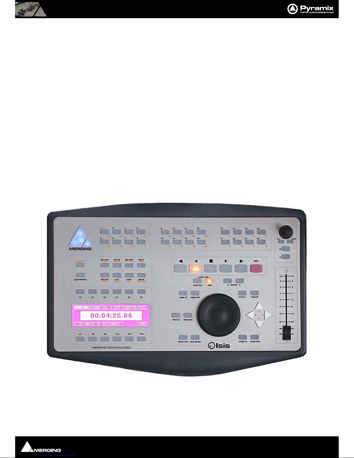
ISIS Remote Controller Overview
ISIS offers a fully user-definable tactile remote control surface for Pyramix editing, recording and mixing functions.
ISIS communicates with Pyramix and/or VCube via Ethernet using Merging's OASIS control protocol to ensure very
high resolution and high-speed communication for all functions.
ISIS Remote Controller main unit has dedicated keys for machine control, jog/shuttle and jog-wheel editing and
the large LCD display offers 12 user-definable and multi-functional keys, which can be soft-labeled to give any
number of user specific functions. All keys are completely user software assignable for total control.
The main unit also has twenty four additional user-definable keys across two layers that can be used as 48 direct
access solo/mute/track arming keys, locators, cue triggers or any other function you choose. The high quality
100mm touch sensitive moving fader and rotary controls can be assigned to any mixer channel with dedicated
Mute, Solo, Automation Read/Write functionality.
For more advanced mixer control an optional ISIS Fader Expansion unit is available with a further 8 touch sensitive
moving faders and rotary controls, each with dedicated Solo, Mute and Read/Write automation keys. The fader
unit also has a range of control bank keys that can layer through mixer configurations with a large number of
strips. Custom mixer arrangements can be user assigned to Presets. The ISIS Fader Expansion unit connects to the
master ISIS Remote Control unit via a local combined RS-232 serial communication and power cable.
Page 9
ISIS User Guide : Chapter 2 - Installation
Page 9
Chapter 2 - Installation
System Requirements
ISIS Remote Controllers will work with any Pyramix system running software version 5.0 or higher. The host PC
must be equipped with a working 10BaseT or better RJ45 Ethernet network connection with TC/IP support
enabled in Windows.
Positioning
Site the unit or units on a suitable surface where they will be properly supported and not subject to any external
heat source. Run the cables in such a manner that there is no strain placed on the connectors at either end and so
there is no danger of their being inadvertently pulled.
Connections - ISIS Controller Main Unit
Note: Please ensure that the host PC and any powered network switch is switched off
before making connections to the ISIS Remote Controllers. Please also ensure the ISIS
power adaptor mains lead is disconnected from the supply and the ISIS Remote Controller main unit power switch is off before making the power connection.
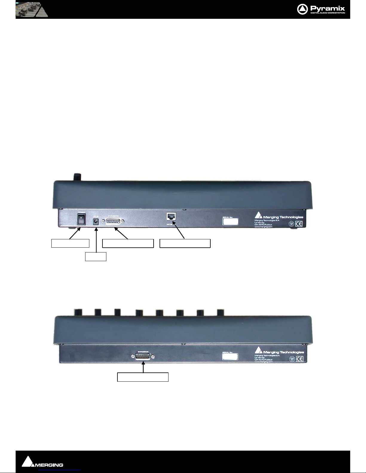
The ISIS Remote Controller main unit has only three physical connections, a low-voltage power jack, an RJ-45
Ethernet socket and a 15-pin D-Sub socket (female) for connecting an ISIS Fader Expansion unit.
Connections - ISIS Fader Expansion Unit
The ISIS Fader Expansion Unit has only one connection, a 15-pin D-Sub socket (male) for connection to an ISIS
Remote Controller main unit.
DC In
Ethernet Socket Expansion Socket
Power Switch
Expansion Socket
Page 10

ISIS User Guide : NETWORK RJ-45 Jack
Page 10
NETWORK RJ-45 Jack
Connect a Cat-5 or better network cable to this socket and connect the other end to a suitable Ethernet port on
the host computer. (Or network switch)
Note: Although some PCs now auto-detect cable type and switch accordingly you are
advised to use a crossover cable for direct connection to a PC. When connecting ISIS to a
network switch use a "normal" network patch cable. (don't connect to the uplink port)
Note: Since ISIS communication is not demanding on network bandwidth, there should
be no need for a separate dedicated RJ-45 network connection. If more than one network connection is present on the host computer, it is not currently possible to assign a
specific port to communicate with the ISIS Remote Controller. This function may be
added in a future software release. In some Wide Area Networks generally found in
larger enterprises the switches may filter out the multicast traffic required to make a connection with an ISIS. In this case a second, dedicated, NIC card will be required for a
direct connection. Please see: Page 14 in Chapter 4 for manual IP address set-up procedure.
EXPANSION Socket
If you are installing an ISIS Fader Expansion unit at the same time, connect the male 15-D-sub plug of the cable
supplied with the ISIS fader Expansion unit to this socket and gently tighten the retaining screws. Connect the
other end of the cable to the EXPANSION socket on the ISIS Fader Expansion unit and gently tighten the retaining
screws.
Power Jack
The power jack accepts a conventional coaxial power plug.
Note: The unit requires a 12V DC at 2.5A
Pin (centre) POSITIVE
Sleeve (Outer) NEGATIVE
Software
All required drivers are included in the Pyramix installation. No additional software is required.
Note: Note: This manual reflects ISIS operation as of Software Version 1.0. Please visit
regularly:
www.merging.com
to check for future updates and enhancements.
Page 11
ISIS User Guide : Chapter 3 - Power up and Initial Configuration
Page 11
Chapter 3 - Power up and Initial Configuration
Power up sequence
• Plug the ISIS Remote Controller power adaptor into a suitable socket and switch on the mains.
• Switch on the ISIS Remote Controller with the rear panel POWER switch. The MERGING logo will light up
blue and the LCD screen will show the following display.
• Power on the host PC and start Pyramix
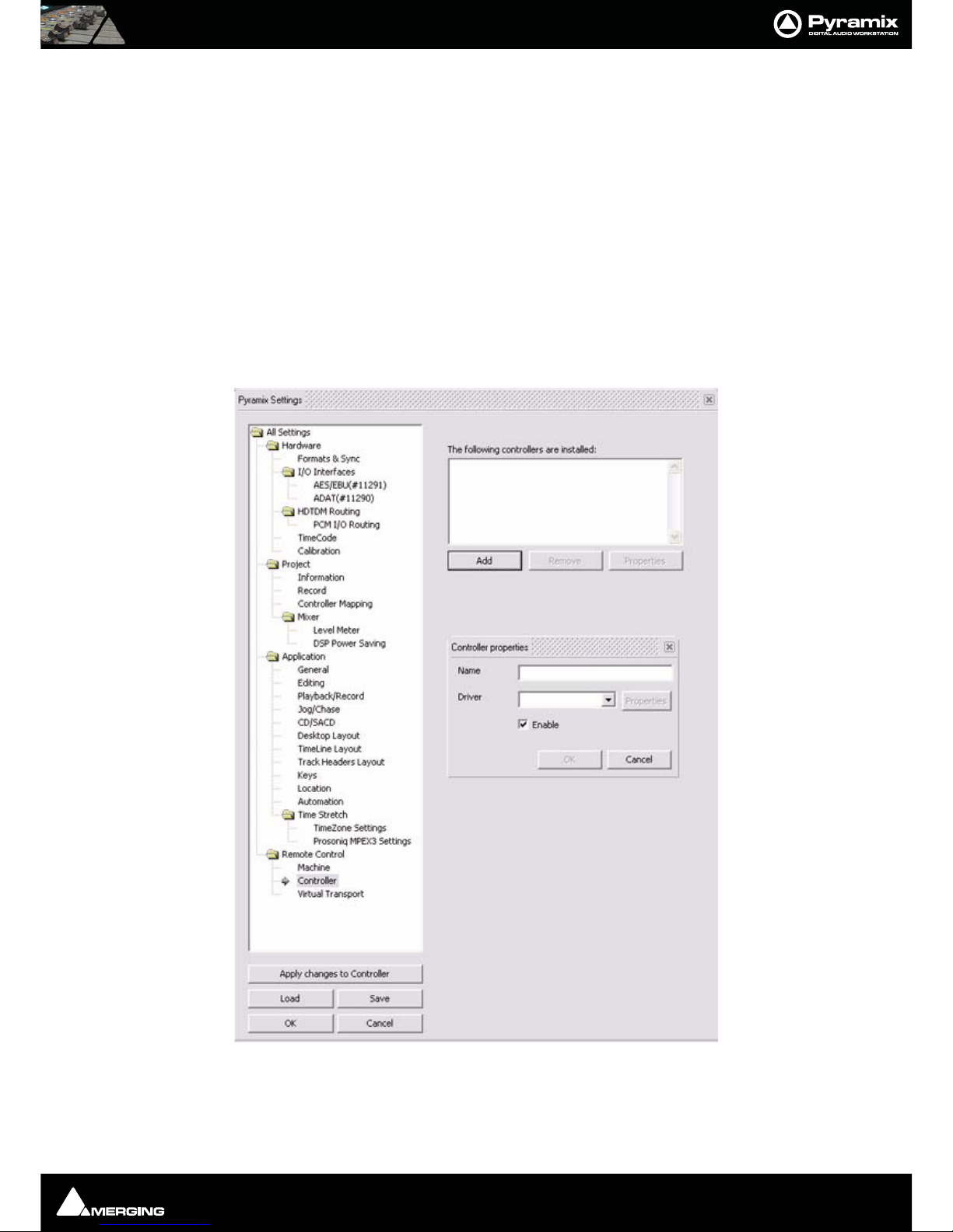
Initial Configuration
• Load a simple Project (or create a new one)
• Go to Settings > All Settings and click on Controller in the Remote Control folder to open the Controllers
pane.
• Click on the Add button to open the Controller Properties dialog
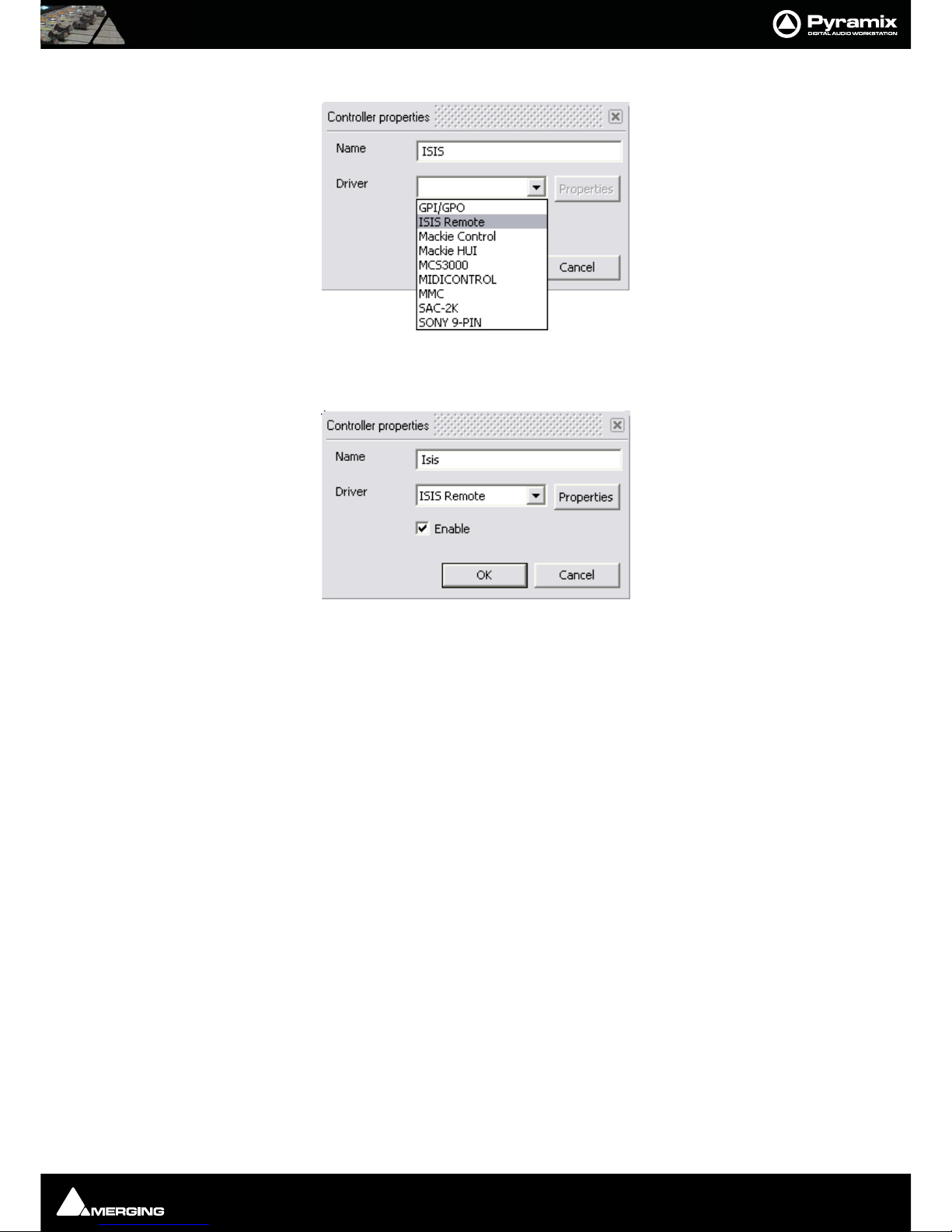
• Type a suitable name for the ISIS Remote Controller. E.g. ISIS
• Choose ISIS Remote from the Driver drop-down list.
Page 12
ISIS User Guide : Chapter 3 - Power up and Initial Configuration
Page 12
•Make sure the Enable box is checked.
•Click on the OK button to close the dialog.
Note: Since ISIS communication is not demanding on network bandwidth, there should
be no need for a separate, dedicated, RJ-45 network connection. If more than one network connection is present on the host computer, it is not currently possible to assign a
specific port to communicate with the ISIS Remote Controller. This function may be
added in a future software release.
If your Ethernet connection is via a router with a DHCP server or there is a DHCP server elsewhere on your network, then this will automatically assign an IP address to the ISIS.
Otherwise, an internally saved IP address is used. To set this, please see the section, 'Setting the ISIS static IP
Address', on Page 16 in Chapter 4.
Note: Direct Ethernet connection of Workstations (i.e.: 1x VCube and 1x Pyramix) with
standard factory default DHCP settings and without a proper DHCP server available in
the network may lead to unexpected behavior, software and or system freezes. (ISIS will
default to fixed IP address, if no DHCP server is available). At all times proper, individual,
TCP-IP address for each machines, assigned either automatically (by a DHCP server, if
available) or manually (Fixed IP) are required.
This caution is not relevant for machines operating without a network connection.
•Click on the OK button at bottom left of the Pyramix Settings window to confirm the changes and close
the Window.
Congratulations! Your new ISIS Remote Controller is now ready for use.
Page 13
ISIS User Guide : Chapter 4 - ISIS TC/IP Address Configuration
Page 13
Chapter 4 - ISIS TC/IP Address Configuration
Windows XP SP2 Firewall
A new Firewall feature has been added to Windows XP SP2. While this is convenient for home internet machines
(for example), it is desirable to turn it off for media production networking needs. So, provided all necessary security has been addressed, either by an external Firewall unit, or by physically removing all Ethernet access to the
outside world, you can:
a) Disable Windows Firewall
Alternatively, if XP SP2 Firewall features are really necessary, keep it active, but:
b) Register ports 6000, 6001 and 6002 as exceptions of Windows Firewall for ISIS.
c) Register VT Server in Windows Firewall exceptions for VCube / Virtual Transport
TC/IP Address Configuration
At all times proper, individual, TCP-IP addresses for each machine are required, assigned either automatically
(DHCP, if available) or manually (Fixed IP), as described below.
When ISIS is powered up it will first attempt to configure its IP address from a DHCP server on the network. (E.g. a
router that incorporates a DHCP server.)
If there is no DHCP server able to assign an IP address, e.g. when there is a direct connection between the PC and
ISIS, the ISIS-RC will use a static IP address that has been saved internally.
Note: The static IP address will only be used if no other IP address has been automatically assigned by DHCP.
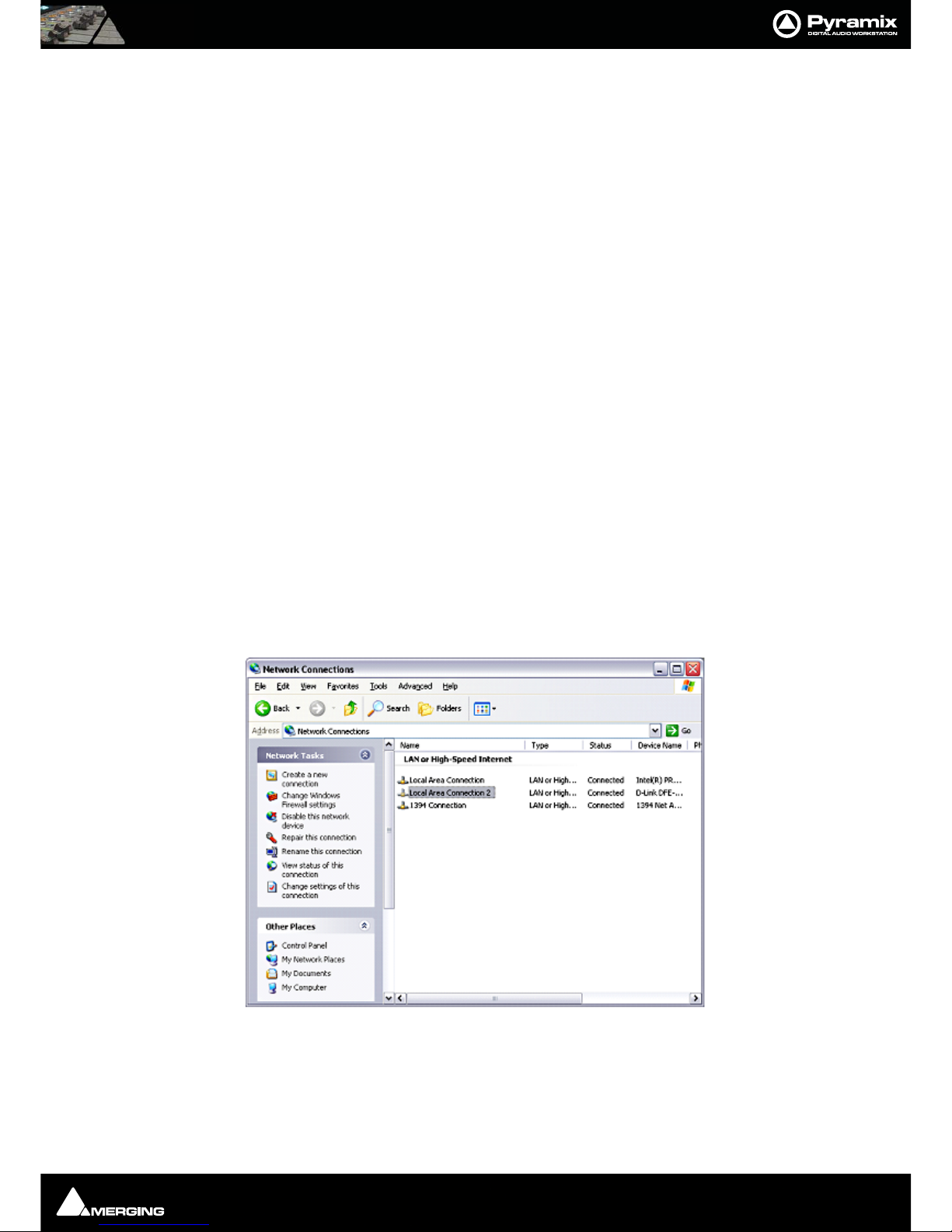
Manual PC TC/IP Address Configuration
If no admin DHCP server is available, manually give each of your machines a unique TCP/IP number. Use Start >
Connect to > Show all connections to open the Network Connections dialog.
Note: In this case, a second NIC has been added for the direct ISIS connection.
Page 14
ISIS User Guide : Chapter 4 - ISIS TC/IP Address Configuration
Page 14
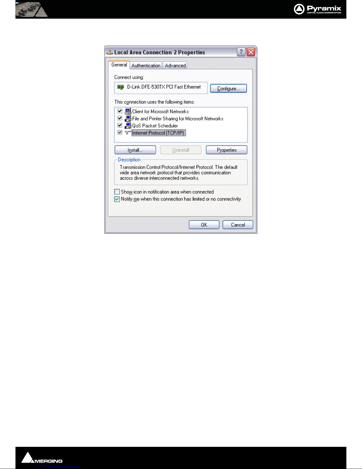
Right-click the relevant network connection and choose Properties from the list to open the Local Area Connection Properties dialog.
Page 15
ISIS User Guide : Chapter 4 - ISIS TC/IP Address Configuration
Page 15
Click on Internet Protocol (TCP/IP) to select it, then click on Properties to open the Internet Protocol (TCP/IP)
Properties dialog.
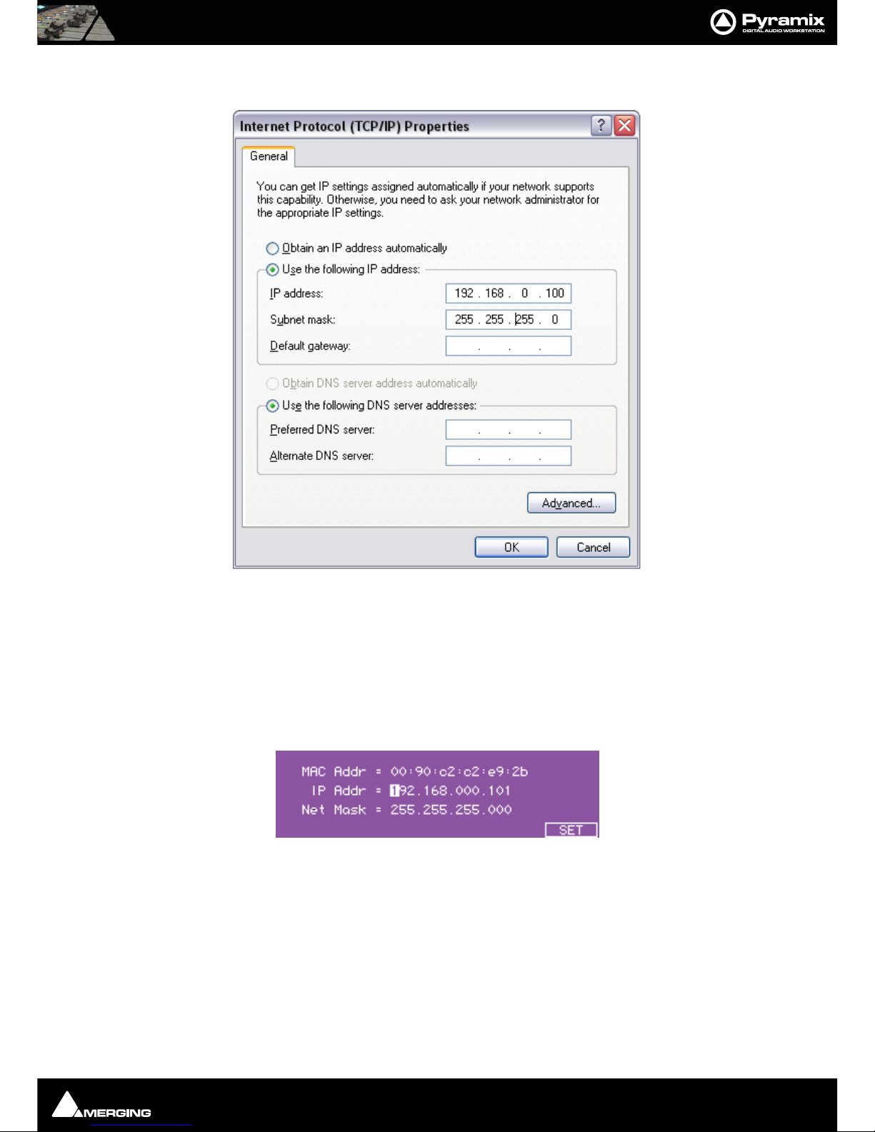
Click Use the following IP address: then click in the IP address: field and type in a suitable value, followed by
clicking in the Subnet mask: field and typing in a suitable value.
Typically, IP addresses can be, respectively: 192.168.0.3 (PMX) 192.168.0.4 ( VCube) and 192.168.0.5 (ISIS), with a
common Subnet mask being 255.255.255.0. No default gateway is necessary.
Setting the ISIS Static IP Address
----------------------------
First, Power up the ISIS while holding down the STOP key for about 5 seconds. This screen appears:
The screen shows the current IP configuration of the ISIS. It will either show any IP address that has been assigned
by DHCP or the static IP address that has been loaded internally.
This screen also shows the hardware MAC address of the ethernet interface in the ISIS Main Unit
To set the IP address, use the CURSOR LEFT and CURSOR RIGHT ISIS keys to select any digit in the IP Address
field.
Use the ISIS CURSOR UP and CURSOR DOWN keys to move between the IP Address and Net Mask fields.
To change the selected digit in either the IP Address or Net Mask fields, use the TRACK SELECT 1-10 keys at the
top of the ISIS
Page 16
ISIS User Guide : Chapter 4 - ISIS TC/IP Address Configuration
Page 16
For example TRACK KEY 1 = '1', TRACK KEY 2 = '2' ... TRACK KEY 10 = '0'
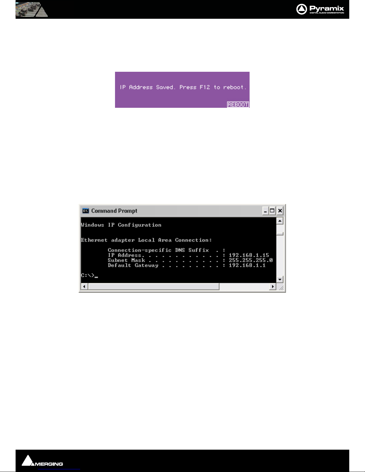
When the IP Address and Net Mask have been set as required, press the SET key (F12). This will save the IP address
and Net Mask as the internal static settings to be used if no other settings are assigned by DHCP.
After you press the SET key this screen appears:
Press the REBOOT key (F12) to reboot the ISIS (or switch the power-off and on again).
Note: The IP configuration can only be saved when there is an established electrical connection between the ISIS and either a Pyramix workstation or Ethernet switch.
Viewing the IP Address
The currently assigned IP Address can be seen in the ISIS Configuration dialog (see image Chapter 5, first page).
Checking IP Configuration
To check the IP Configuration of the machine you are working on do the following: Open a Command Prompt window. (Start > All programs > Accessories > Command Prompt) then type in the following command: IPCONFIG
followed by Enter. The IP configuration for the machine will be shown like this:
Checking Network Connections
Using "Ping":
To check that the connections you have set up are operational do the following:
Open a Command Prompt window. (Start > All programs > Accessories > Command Prompt) then type in the
following command:
PING 192.168.0.3 (or whatever TCP/IP address is currently assigned to the workstation or device you wish to
check) followed by Enter then wait for the machine to reply. Repeat the process for all other connected Workstations / Controllers.
Using Windows Explorer:
In a Windows Explorer window, right-click on My Network Places and choose Explore > Entire Network /
Microsoft Windows Network / Workgroup or Domain (choose whichever is appropriate) then verify that all
Pyramix and VCube workstations can search/see each other on the network, including shared hard drives and
folders. Having all machines in the same "Workgroup" helps. (default workgroup is either "WORKGROUP" or
"MSHOME")
Page 17
ISIS User Guide : Chapter 5 - LCD Contrast & LED Brightness
Page 17
Note: With Windows XP, it may take some time for the TCP/IP lists to be appropriately
updated to reflect the complete network topology on all machines. (Particularly when
additional computers are added to a large existing network). Please allow for time for
these operations to be properly carried out in the background. It may in fact take something like 10 to 50 minutes depending on the size of the network. (In certain situations,
E.g. a small 2 machine peer-to-peer network, rebooting both machines may speed up
the process).
Chapter 5 - LCD Contrast & LED Brightness
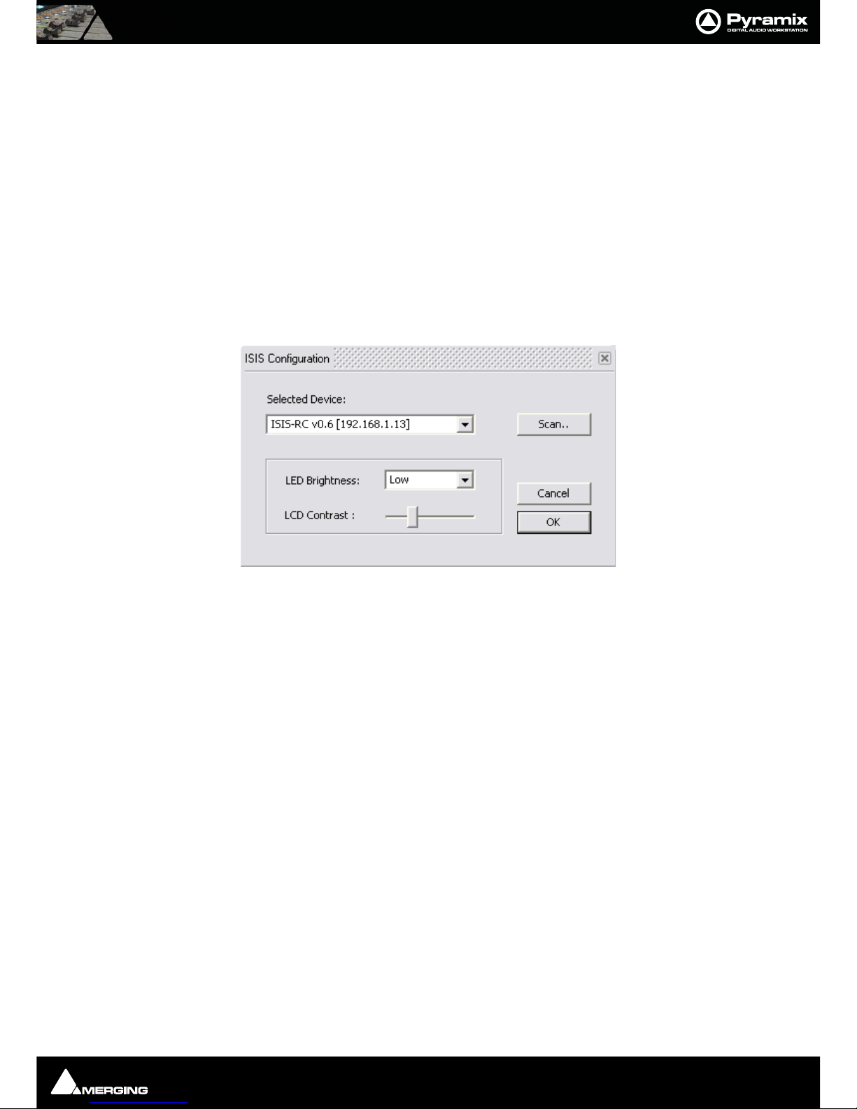
If lighting conditions require, the ISIS LCD contrast and LED brightness are adjustable. Go to Settings > All Settings and click on Controller in the Remote Control folder to open the Controllers pane. Click on ISIS or what-
ever you named the ISIS controller in the The following controllers are installed list: Click on Properties to open
the Controller Properties dialog. Click on Properties to open the ISIS Configuration dialog.
LCD Contrast
Simply click and drag on the LCD Contrast : slider to adjust the contrast. Changes are immediately visible on the
ISIS display.
LED Brightness
The LED Brightness: combo box offers a choice of Low, Medium or High brightness levels. Any change is immedi-
ately reflected in the ISIS LEDs.
When adjustments are complete, click on the OK button to accept the changes and close the dialog. Alternatively,
click on Cancel to reject any changes and close the dialog. Click on OK in the Controller Properties dialog to
close it flowed by OK in the Pyramix Settings window to close it.
Page 18

ISIS User Guide : Chapter 6 - The Default Configuration
Page 18
Chapter 6 - The Default Configuration
ISIS is fully functional from the moment it is installed thanks to the default configuration. Almost every ISIS key is
user programmable but we suggest that you take some time to explore and become familiar with the default configuration before changing any key functions.
Surface Labels
The black legends on the ISIS control surface indicate the default key functions
The SHIFT key
Many keys have alternative functions accessed by holding down the SHIFT key while pressing the function key.
Orange legends on the ISIS control surface indicate SHIFTed functions.
Channel Strip Functions
By default, the channel strip on the ISIS Main Unit is assigned as a Master/Monitor Strip.
In the Master/Monitor Strip, the controls function as follows:
• ENCODER - Monitor Volume
• ENCODER (Press) - Reset Monitor Reference Volume
• PLAY - Master automation Play SHIFT + PLAY - Master/Monitor bus Play
• WRITE - Master automation Write SHIFT + WRITE Master/Monitor bus Write
PLAY & WRITE lit - Auto-Write
PLAY & WRITE off - Off/Isolate
• MUTE - Monitor volume mute
• SOLO - Monitor Volume dim
• FA DE R - Master Mix gain
The channel strip on the ISIS Main Unit can also be remapped to control any Pyramix Mixer Strip.
Please see Chapter 5 - User Configuration for details.
Page 19

ISIS User Guide : Chapter 6 - The Default Configuration
Page 19
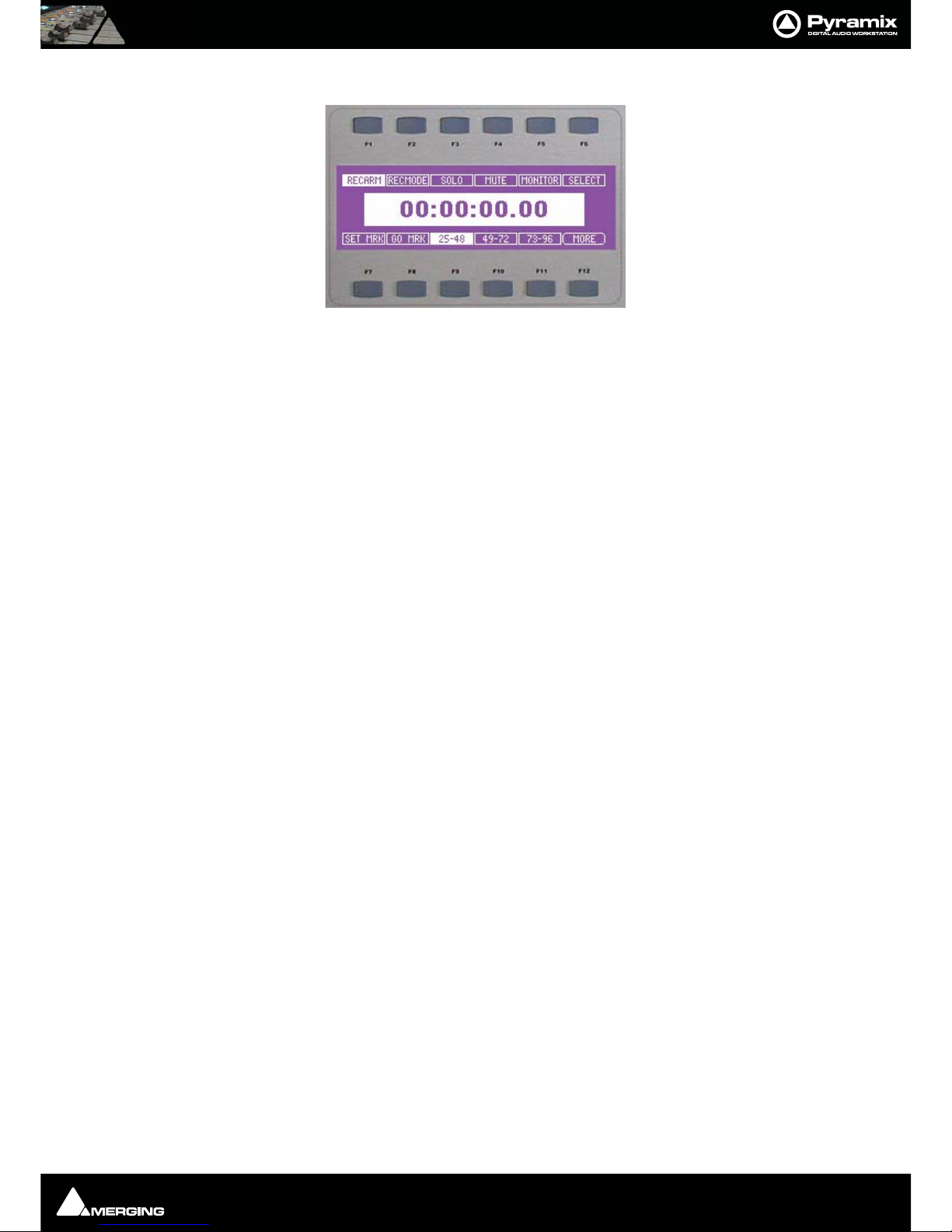
LCD Display and Function Soft Keys
The LCD display shows the main Time Scale Bar's current Playhead Cursor position TimeCode value in the centre of
every page. The Function soft keys labeled F1 to F12 are arranged in two rows of six above and below the LCD display. Current function of each key is shown in the LCD display.
This is the first fixed default page you will see when the ISIS is enabled either in the Settings menu or by loading a
project that already has ISIS enabled.
Navigating LCD Pages
F12, labeled MORE, cycles through all available pages. F12 is currently a fixed assignment so MORE is available in
all pages. The pages appear in this order:
• Track Select Key functions and Markers (fixed page)
• Machine Select (fixed page)
• Default User Page 1 (User definable)
• Any other User Pages (defined by the user)
• Monitoring (fixed page)
A subsequent press on MORE returns to the first page.
Direct Access to LCD Pages
Pressing and holding the F12 (MORE) key and one of the 1-24 keys gives direct access to the LCD page corresponding to that number. Choosing a number with no corresponding LCD page simply takes you to the highest
number page that exists.
Page 20
ISIS User Guide : Chapter 6 - The Default Configuration
Page 20
Track Select Key Functions and Markers Page
The first fixed LCD page determines the function of the track select keys and sets and locates Markers.
By default the Key 1 to 24 (the Track Select keys) are assigned to the functions SELECTOR 1 to SELECTOR 24 (and
SELECTOR 25 to SELECTOR 48 as SHIFT functions). Providing these assignments are not altered by the user, in
this page the F1 to F6 keys are is used to determine how the Track Select keys function on the corresponding
track.
F1 RECARM (Record Arm) A single press on the relevant Track select Key arms the track for recording, a second
press returns to Safe (replay) Use this for simple recordings where speed and simplicity are important.
F2 RECMODE (Record Mode) A single press on the relevant Track select Key arms the track for recording, a second
press arms for Punch In mode and a third press returns to Safe (replay). Use this instead of F1 for more complex
sessions where Punch record is to be employed.
F3 Solo
F4 Mute
F5 MONITOR A press on the relevant Track Select key sets the Monitoring mode, cycling through Replay, Input
and Auto
F6 Select A press on the relevant Track Select key selects the track.
F7 enters Set Marker mode
A marker numbered from 1 to 10 will be set at the current Playhead Cursor position when the corresponding
Track Select key is pressed. The Marker shown on the Pyramix screen will have two numbers. The first, in brackets,
shows the number of the corresponding Track Select key (and keyboard Hotkey) and the second shows the number of the Marker in the Markers list.
F8 enters Goto Marker mode The transport will locate to a Marker when the Track Select key corresponding to an
existing marker is pressed.
F9 25 - 48 Select track access mode from 25 to 48
F10 49 - 72 Select track access mode from 49 to 72
F11 73 - 96 Select track access mode from 73 - 96
F12 MORE
Global Shortcuts
Shift + F1 RECARM arm all tracks, if all armed unarm all
Shift + F2 RECMODE toggle through rec mode available for all tracks
Shift + F3 SOLO unsolo all the soloed tracks
Shift + F4 MUTE unmute all the muted tracks
Shift + F5 MONITOR toggle through monitor mode available for all tracks
Page 21
ISIS User Guide : Chapter 6 - The Default Configuration
Page 21
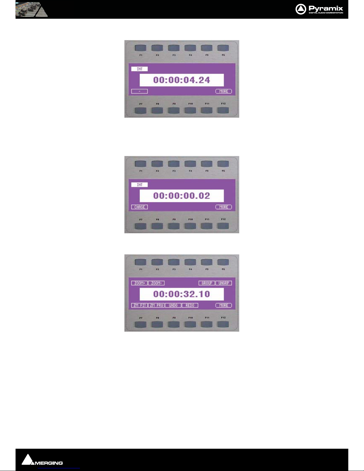
Machine Select page
This page shows up to 5 machines on F1 to F5 (F1, the Internal Machine, is always present). Pressing F1 to F5
selects the corresponding machine. F7 to F11 labels show the current chase status of the machine above. Pressing F7 to F11 controls the CHASE state of the corresponding machine. Pressing SHIFT plus
F7 to F11 controls the AUTO CHASE state of the corresponding machine.
First User page (default)
The assignments on this page can be changed by the user. As supplied the First user Page has the following functions:
F1 ZOOM + (Zoom In)
F2 ZOOM - (Zoom Out)
F3 No assignment
F4 No Assignment
F5 GROUP
F6 UNGRP (Ungroup)
F7 ZM FIT (Zoom to fit in window)
Page 22

ISIS User Guide : Chapter 6 - The Default Configuration
Page 22
F6 ZM PREV (Zoom Previous)
F9 UNDO
F10 REDO
F11 No assignment
F12 MORE
Monitor page
This page controls the Pyramix Monitor functions as follows:
F1 L Mute Front Left speaker output. With SHIFT Mute Left Inner speaker output.
F2 C Mute Front Centre speaker output.
F3 R Mute Front Right speaker output. With SHIFT Mute Right Inner speaker output.
F4 INPUT + Monitor Next Input. With SHIFT Monitor Previous Input
F5 SPKR + Monitor Next Output Speaker Set. With SHIFT Monitor Previous Output Speaker
Set
F6 DMIX+ Monitor Next Output Downmix. With SHIFT Monitor Previous Output Downmix
F7 LS Mute Left Surround Speaker Output
F8 LFE Mute Subwoofer Output
F9 RS Mute Right Surround Speaker Output -
F10 RESET Reset Speakers
F11 OPMODE Monitor Operation Mode. Cyles through Mute, Solo and SoloX functions for the Speaker
Mute F keys
F12 MORE
Page 23

ISIS User Guide : Chapter 6 - The Default Configuration
Page 23
Other Keys Default Function Mapping
Transport Control Group
REWIND = Fast Rewind
REV PLAY = Play Reverse
STOP = Stop
PLAY = Play
FF = Fast Forward
REC = Record
Jog Wheel Group
SHUTTLE = Jog Wheel Mode - Shuttle + SHIFT = Jog Wheel Mode - Jump
JOG = Jog Wheel Mode - Jog + SHIFT = Jog Wheel Mode - Loop Jog
< NUDGE = Nudge -1 Frame
> NUDGE = Nudge +1 Frame
FADE IN = Trim Fade In
FADE OUT = Trim Fade Out
SYNC P = Set Sync Point to Cursor + SHIFT = Send Sync Point to Cursor
FREEZE = Freeze External Machine
TRIM IN = Trim In
TRIM OUT = Trim Out
CURSOR L = Select Previous Clip
CURSOR R = Select Next Clip
CURSOR UP = Select Previous Track
CURSOR DOWN = Select Next Track
MOVE CLIP = Move
SLIP MEDIA = Slip Media
MARK IN = Mark In to Cursor
MARK OUT = Mark Out to Cursor
Page 24

ISIS User Guide : Chapter 6 - The Default Configuration
Page 24
Edit Group
SHIFT = Shift (Fixed Assignment)
AUTO-RIPPLE = Auto-Ripple
SEL CLIP = Select Clip(s) under Cursor
SHIFT CLEAR = Undo Selection
SEL IN = Set Selection Start to Cursor
SHIFT CUT IN =Trim In to Cursor
SEL OUT = Set Selection End to Cursor
SHIFT CUT OUT = Trim Out to Cursor
SPLIT = Split Clip(s) at Cursor
SHIFT TRIM =Trim
DELETE = Delete
SHIFT UNDO =Undo
CUT = Cut
SHIFT REDO =Redo
COPY = Copy
SHIFT FILL = Fill Selection
PAS TE = Pa ste
SHIFT REPLACE = Replace Selection
Page 25

ISIS User Guide : Chapter 7 - Jog/Shuttle Tuning
Page 25
Chapter 7 - Jog/Shuttle Tuning
To fine-tune jog/shuttle performance, please go to the Jog Wheel Settings section of the Settings > All Settings
> Application > Jog/Chase page.
Jog Wheel Settings
Controller The combo box offers a choice of hardware controller presets if ISIS is not already
selected, select it.
Auto Jog on move When ticked, any movement of the ISIS Jog Wheel enters Jog mode. When not
ticked, the ISIS JOG button must be pressed to enter Jog mode.
Auto-Solo Selection When ticked, all tracks in the current selection are Solo'd when jogging.
Speed ceiling Sets the maximum jog speed from a choice of 1X, 2X, 4X or 8X play speed
Smoothing Filter The Smoothing Filter parameter determines the length of the "fade in" and "fade
out" when beginning and ending scrubbing. Enter the required value in the box
expressed in video frames.
Flywheel inertia Low follows the actual movements as sent by the jog wheel. High passes the
actual movement through a smoothing filter. So, when the slider is set to Low the
Smoothing Filter parameters have no effect.
For sound to picture work where tight sync to picture is required use a setting
biased to Low. For a more pronounced flywheel effect choose a Higher setting.The
Middle position is a good starting point.
Transient response accelerator Optimizes Pyramix's reactivity to jog moves, settings range from
Smooth to Accurate.
When the slider approaches Accurate there may be some strange undesirable
effects.
Jog - sensitivity - seconds per revolution
Sets the time moved in one revolution of the jog wheel. Type the required value in
the box.
Shuttle - sensitivity - revolution to get nominal
Sets the fraction of a revolution required to maintain nominal speed. E.g. an entry
of 0.25 will require a quarter of a turn clockwise to achieve nominal speed.
Jump - sensitivity - number of revolutions to cross over the timeline
Sets the number of revolutions of the jog wheel required to traverse the visible
timeline. I.e. actual speed depends on Zoom factor.
Note: Note: If any of the Jog Wheel Settings are altered, the combo box changes to show
User Defined to reflect this. User defined settings can be saved for future use with the
Load and Save Pyramix settings functions.
Page 26

ISIS User Guide : Chapter 8 - User Configuration
Page 26
Chapter 8 - User Configuration
The ISIS is a very flexible controller. User configurations to suit individual applications and user preferences can be
constructed and stored for future use. Configurations can be stored in libraries and with individual projects.
User configuration is undertaken as follows:
Choose Settings > All Settings > Project > Controller Mapping . Click on ISIS in the The following controllers
are installed: list and click on Properties to open the ISIS Control Mapping window. (Or double-click the list
entry.)
Note: Note: The dialog opens ready to configure the Main ISIS Controller. To configure
the Fader Expansion Unit click on the Fader Expansion tab in the top left corner of the
window to switch the left-hand pane to the Fader Expansion Unit.
Mapping Functions to ISIS Keys
The right-hand pane has tabbed pages listing every mappable function in Pyramix. To map a function to an ISIS
key or fader strip simply click on the required function to highlight it and click on the destination ISIS key in the
left-hand, Controller, pane to highlight it.
Note: Note: Most ISIS keys can each have two functions assigned to them, Function and
Shift Function. Therefore when clicking in the Controller pane, be sure to click in the
appropriate column as well as row.
When the desired Pyramix function and ISIS key are both highlighted, simply click on the Assign button.
The controller pane will update to reflect the new mapping.
Page 27

ISIS User Guide : Chapter 8 - User Configuration
Page 27
Removing a Mapping
To remove a mapping from an ISIS control:
In the Controller pane highlight the Function or Shift Function you wish to remove. Then simply click on the
Remove button.
The controller pane will update to reflect the new mapping.
Special Mappings
Selector
In the Track s tab page the functions Selector 1 to Selector 48 are special mappings to enable ISIS to switch the
function of the Track Select keys between RECARM, RECMODE, SOLO, MUTE and SELECT using the function
keys. Similarly, when the functions Set Marker Selector and Goto Marker Selector are mapped to LCD function
keys, they are used in conjunction with the Track Select Keys to set and locate markers.
Control Strip
Control strips do not have a SHIFT mapping because the SHIFT functions are part of the Mixer Strip mapping. If a
Control Strip is mapped to a surround Master/Monitor strip, the Play and Write buttons control the global Mixer
automation. Used with SHIFT they control the Master/Monitor bus automation.
Invalid Mappings
Certain mappings are invalid. E.g. a Mixer Strip to an ISIS key. If you inadvertently attempt to make such a mapping
a warning dialog will appear and the mapping will not be allowed.
LCD User Pages
As detailed above, User Page 1 has default functions already assigned to it. We suggest you leave User Page 1
alone until you are confident about User Mapping.
At the bottom of the Controller pane there are two tabs for User Page 1 and New User Page…
Clicking on the New User Page tab opens the ISIS Control Create New LCD Page dialog.
Click on Ye s to create a new User Page. The Function Key entries will go blank and a new tab will appear labeled
User Page X (X is the User Page number incremented from the last existing User Page.
Mapping functions to LCD Function keys is carried out in the same manner as mapping functions to the other ISIS
keys and strips with these differences.
• The LCD Function Keys do not have a SHIFTed function.
• Double-clicking in the Label field of a Function key allows the Label to be changed.
Note: Note: Labels can be up to six characters long including spaces.
Page 28

ISIS User Guide : Chapter 8 - User Configuration
Page 28
Mapping Mixer Strips to ISIS Controller Strips
The fader control strip on the ISIS remote controller can also be remapped to control any Pyramix Mixer Strip.
When assigned as a Mixer Strip (Mixer Strip 1, Mixer Strip 2 etc..), the controls function as:
• ENCODER Mixer channel Pan/Balance (with SHIFT Front/Rear)
• ENCODER (Press)
• PLAY Mixer Strip Play
• WRITE Mixer Strip Write
• MUTE Mixer channel Mute
• SOLO Mixer channel Solo
• FA DE R Mixer channel Gain
Note: Stereo strips behave in the same way as Pyramix strips with Mirror Y Linking
applied in the Surround Control window. The linking does not have to be made in Pyramix, it is part of the mapping.
Master/Monitor Strip
When the fader control strip on the ISIS Main Unit or a fader control strip on the ISIS Fader Expander is assigned as
a Master/Monitor Strip, the controls function as follows:
• ENCODER Monitor Volume
• ENCODER (Press) Reset Monitor Reference Volume
• PLAY Master automation play
• WRITE Master automation write
• MUTE Monitor volume mute
• SOLO Monitor Volume dim
• FA DE R Bus gain
Automation
Note: The automation buttons behave differently when assigned to Mixer Strips as
opposed to Master/Monitor Bus Strips.
In a control strip mapped to a Mixer Strip the PLAY and WRITE keys toggle on and off independently and control
the Strip's automation mode as follows:
• PLAY Off / WRITE Off = Isolate
• PLAY On / WRITE Off = Play
• PLAY Off / WRITE On = Record
• PLAY On / WRITE On = Auto-Write
In a control strip mapped to a Master/Monitor Bus the PLAY and WRITE keys toggle on and off and exclusively.
I.e. only one can be lit at a time. They control the Strip's automation mode as follows:
• PLAY Off / WRITE Off = Master Automation Off
• PLAY On / WRITE Off = Master Automation Play
• PLAY Off / WRITE On = Master Automation Record
Page 29

ISIS User Guide : Chapter 8 - User Configuration
Page 29
Saving and loading Mappings
User Mappings
Clicking on the Load or Save buttons opens a Windows File Browser. ISIS Template Files with .map extension can
be saved or loaded at will. Clicking on Load Default opens this dialog:
Click on Ye s to overwrite the current ISIS mapping with the default mapping or No to cancel.
Default mappings
Clicking on Save Default opens this dialog:
Click on Ye s to set the current mapping as the default mapping for all projects or No to cancel.
Mappable Functions
A complete list of mappable functions can be found in Appendix I
Tips and Tricks
Auto-Solo
When any of the Jog modes are activated (Jog, Tri m, Fade etc.) you may only wish to listen to the selection. Check
the Auto-Solo Selection box in the Settings > All Settings > Application > Jog/Chase : Jog Settings section. If
you wish to keep one or more tracks audible that are not part of the selection simply check the SF (solo-safe) box
on the strip.
Page 30

ISIS User Guide : Chapter 9 - ISIS Fader Expansion
Page 30
Chapter 9 - ISIS Fader Expansion
The ISIS Fader Expansion Unit offers greatly increased mixing capabilities.
• The eight Control Strips are identical to the Control Strip on the ISIS main Unit.
• By default, the cursor keys are unmapped.
• The fader control strips are automatically assigned to Pyramix mixer strips in banks of 8.
• The ten keys on the left of the unit bank switch the faders. Pressing '1-8' will assign the faders to Mixer
Strip 1-8, pressing '9-16' will assign the faders to Mixer Strip 9-16 etc.
• When used in conjunction with the latching PRESET key, these buttons switch between the ten possible
Mixer PRESETS.
•Each Mixer PRESET allows any Pyramix Mixer strip to be assigned to any physical ISIS Control Strip.
•Mixer PRESETS are assigned in the Fader Expansion page of the ISIS Control Mapping Window.
Page 31

ISIS User Guide : Chapter 10 - Crossfade Editing with ISIS
Page 31
Chapter 10 - Crossfade Editing with ISIS
ISIS has very powerful editing capabilities in conjunction with the Fade Editor in Pyramix. To access these features
you will need to load a template file into ISIS as Follows:
• Load the Xfades mapping file: go to All Settings > Project > Controller Mapping and select the ISIS
entry in the The following controllers are installed list by clicking on it.
•Click on the Properties button to open the ISIS Control Mapping window.
•Click on Load to open a browser window and navigate to C:\Program Files\Merging Technolo-
gies\Pyramix Virtual Studio\Templates\Isis\Xfade Editing and select the ISIS Template XFadesMapping 2LCD.map file.
•Click on the Open button to close the browser and load the mapping.
•Click on OK to exit the ISIS Control Mapping dialog.
You will now find that there are two new ISIS LCD Pages. The first is for control:
Crossfade Page
F1 T- LOCK When selected Trim operations affect both sides of the crossfade
F2 AU O Audition cross-fade Out
F3 AU I Audition cross-fade In
F4 AU X Audition cross-fade
F5 PREV Jump to Previous crossfade
F6 NEXT Jump to Next crossfade
F7 --| Trim outgoing Cue
F6 |\ Adjust fade Out
F9 /| Adjust fade In
F10 |-- Trim incoming Cue
F11 UNDO Undoes all trim and fade adjustments since the crossfade was selected this time
F12 MORE
Page 32
ISIS User Guide : Chapter 10 - Crossfade Editing with ISIS
Page 32
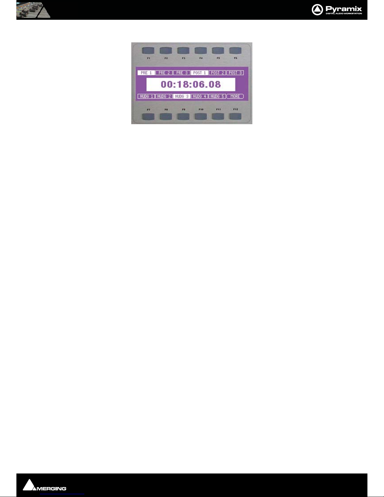
Crossfade Parameters
The second page is for choosing parameters:
F1-F3 Select the audition Pre-roll preset values (1 to 3)(as in the Fade Editor)
F4-F6 Select the audition Post-roll preset values (1 to 3) (as in the Fade Editor)
F7-F11 Select the Nudge preset value. (1 to 5)
F12 MORE
Note: Note: Pre and Post Roll Settings are made in All Settings > Application > Playback/Record in the Pre/Post Roll Settings section.
Nudge value settings are made in All Settings > Application > Editing in the Nudge
settings section.
Operation
With these tools, you can both jog-wheel and nudge-edit the cross-fades in the same context:
Select the operation (Tr im , Fade) with the left hand on the LCD page and adjust the value with the right hand
using either the jog-wheel or the nudge arrows.
Note: Note: When going from nudge to jog-wheel, you need to re-select the wheel
mode (jog or shuttle) manually.
When you are happy with the current cross-fade NEXT accepts the changes you've made and takes you straight to
the next cross-fade, open and ready for adjustment. Using these tools it is possible to edit, for example dialogue,
very rapidly.
Page 33

ISIS User Guide : Appendix 1 - Mappable Functions
Page 33
Appendix 1 - Mappable Functions
Mappable functions are arranged in tabbed pages on the right-hand side of the ISIS Control Mapping window.
The following tables show all functions available for mapping to ISIS with default keyboard shortcuts and brief
function descriptions. For fuller explanations of any of the functions please see the main Pyramix User Manual.
Mixer
Master/Monitor Strip
Mixer Strip 1
to
Mixer Strip 80
Monitor
Surround Mix Input
Surround Mix Input
Surround Mix Input
Surround Mix Input
Surround Mix Input
Surround Mix Input
Surround Mix Input
Next Input
Next Output DownMix
Next Output SpeakerSet
Previous Input
Previous Output DownMix
Previous Output SpeakerSet
None Speakers
L Speakers
C Speakers
R Speakers
Ls Speakers
Rs Speakers
Lfe Speakers
Lc Speakers
Rc Speakers
Cs Speakers
Center Speakers
Operation Mode Speakers
Reset Speakers
Volu me
Volume Dim
Volume Mute
Volume Ref
Active Machine
Toggle machines NUM PLUS Toggle between machines
Stop K, NUM 0 Stop
Pause Pause
Play L Play
Record NUM DECIMAL Record
Fast Forward SHIFT + F8 Fast Forward
Fast Rewind SHIFT + F 7 Fast Rewi nd
Scan Forward CTRL + F8 Scan Forward
Scan Rewind CTRL + F7 Scan Rewind
Start HOME, SHIFT + F5 Start
End END, SHIFT + F6 End
Play Reverse CTRL + SPACE, J Play Reverse
Play 1/2 SHIFT + SPACE Play 1/2
Play 1/2 Reverse CTRL + SHIFT + SPACE Play 1/2 Reverse
Mixer
Monitor
Active Machine
Page 34

ISIS User Guide : Appendix 1 - Mappable Functions
Page 34
Play 1/4 ALT + SPACE Play 1/4
Play 1/4 Reverse CTRL + ALT + SPACE Play 1/4 Reverse
Play 1/16 SHIFT + ALT + SPACE Play 1/16
Play 1/16 Reverse CTRL + SHIFT + ALT + SPACE Play 1/16 Reverse
Play 2x Play 2x
Play 2x Reverse Play 2x Reverse
Play 4x P Play 4x
Play 4x Reverse U Play 4x Reverse
Toggle Play/Stop SPACE Toggle Play/Stop
Toggle Play/Pause NUM ENTER Toggle Play/Pause
Tog gle P lay /Rec ord Toggle Play/Record
Goto TimeCode Goto TimeCode
Nudge +1 frame Nudge +1 frame
Nudge -1 frame Nudge -1 frame
Set Loop In Set Loop In
Set Loop Out Set Loop Out
Goto Loop In Goto Loop In
Goto Loop Out Goto Loop Out
Chase CTRL + F1 Chase
Store Chase Offset Store Chase Offset
Jog-Wheel Mode - Jog Jog-Wheel Mode - Jog
Jog-Wheel Mode - Shuttle Jog-Wheel Mode - Shuttle
Jog-Wheel Mode - Loop Jog-Wheel Mode - Loop
Jog-Wheel Mode - Jump Jog-Wheel Mode - Jump
Jog-Wheel Mode - Off Jog-Wheel Mode - Off
Automation
Automation Off Automation system is disabled
Automation Play Automation system will playback any previously recorded automation
data
Automation Write Automation system will playback any previously recorded automation
data and record new automation data for all enabled controls
Automation Snapshot Creates an automation key frame at cursor position, for all armed automa-
tion controls
Automation Snapshot Range Places automation key frames at the in /out cursor positions, for all cur-
rently armed automation controls
Delete Selected Points Deletes all automation points inside selected region
Cut Selected Points Cuts all automation points inside selected region
Copy Selected Points Copies all automation points inside selected region
Paste Points to Cursor Pastes all copied or cut automation points at the cursor on selected track
Paste Points to Original TC Pastes all copied or cut automation points at original TimeCode on
selected track
Auto-Write Mode - Write & Release Sets the Auto-Write Mode to Write & Release
Auto-Write Mode - Write & Hold Sets the Auto-Write Mode to Write & Hold
Auto-Write Mode - Update & Release Sets the Auto-Write Mode to Update & Release
Auto-Write Mode - Update & Hold Sets the Auto-Write Mode to Update & Hold
Release Mode - Snap Sets the Automation Release Mode to Snap
Release Mode - Auto-Release Sets the Automation Release Mode to Auto-Release
Release Mode - Write to Next Sets the Automation Release Mode to Write to Next
Release Mode - Write to End Sets the Automation Release Mode to Write to End
Release Auto-Writing CTRL + ALT + ESC Releases all controls currently recording automation
Automation Tracks Enables the automation versions for a specific control to be displayed.
Locate control in the tree view, double-click on control to update the
Automation Track Versions window
Automation Settings Opens automation settings dialog
Clips
Select All CTRL + A Select all clips on Timeline
Select All to Mark In CTRL + I Select all clips on Timeline, to Mark In Point
Automation
Clips
Page 35

ISIS User Guide : Appendix 1 - Mappable Functions
Page 35
Select All between Marks CTRL + B Select all clips on Timeline, between In/Out Marks
Select All from Mark Out CTRL + J Select all clips on Timeline, from Mark Out Point
Select Source F9 Select all clips on current audio track
Select Online Clips Select all clips that reference currently mounted Media
Select Offline Clips Select all clips that reference no currently mounted Media
Deselect All ESC, CTRL + D Deselect all currently selected clips
Select Previous Clip Num LEFT Select clip to left of currently selected clip
Select Next Clip Num RIGHT Select clip to right of currently selected clip
Add Previous Clip to Selection SHIFT + Num LEFT Apply selection to clip to left of currently selected clip
Add Next Clip to Selection SHIFT + Num RIGHT Apply selection to clip to right selected clip
Add all Preceding Clips to Selection Apply selection to all clips preceding selected clip
Add all Following Clips to Selection Apply selection to all clips following selected clip
Nudge to Previous Edit SHIFT + ALT + LEFT Nudges selected clip left (earlier in time) to the previous edit points in the
track or marks in the editor
Nudge to Next Edit SHIFT + ALT + RIGHT Nudges the selected clip right (later in time) to the next edit points in the
track or marks in the editor
Nudge to Left ALT + LEFT Nudges selected clip left (earlier in time) by an amount equal to the cur-
rent Nudge setting
Nudge to Right ALT + RIGHT Nudges the selected clip right (later in time) by an amount equal to the
current Nudge setting
Nudge to Left Custom ALT + PGUP Nudges the selected clip left (earlier in time) by an amount entered with
the keyboard
Nudge to Right Custom ALT + PGDOWN Nudges the selected clip right (later in time) by an amount entered with
the keyboard
Nudge to Left Custom in Bars/Beats Nudges the selected clip left (earlier in time) by an amount entered in
Bars/Beats with the keyboard
Nudge to Right Custom in Bars/Beats Nudges the selected clip right (later in time) by an amount entered in
Bars/Beats with the keyboard
Nudge In to Left Nudges selected clip start left (earlier in time) by an amount equal to the
current Nudge setting
Nudge In to Right Nudges the selected clip start right (later in time) by an amount equal to
the current Nudge setting
Nudge Out to Left Nudges selected clip end left (earlier in time) by an amount equal to the
current Nudge setting
Nudge Out to Right Nudges the selected clip end right (later in time) by an amount equal to
the current Nudge setting
Nudge Media to Left Nudges selected clip media left (earlier in time) by an amount equal to
the current Nudge setting
Nudge Media to R ight Nudges the selected clip media right (later in time) by an amount equal to
the current Nudge setting
Move Up ALT + UP Moves selected clip or region up to the adjacent track above it
Move Down ALT + DOWN Moves selected clip or region up to the adjacent track below it
Move Up with Fade CTRL + ALT + UP Moves selected clip or region up to the adjacent track above it. If there is
another clip on the adjacent track at that location, it will interact with it by
crossfading
Move Down with Fade CTRL + ALT + DOWN Moves selected clip or region up to the adjacent track below it. If there is
another clip on the adjacent track at that location, it will interact with it by
crossfading
Nudge Setting 1 CTRL + 1 Apply Nudge Setting 1
Nudge Setting 2 CTRL + 2 Apply Nudge Setting 2
Nudge Setting 3 CTRL + 3 Apply Nudge Setting 3
Nudge Setting 4 CTRL + 4 Apply Nudge Setting 4
Nudge Setting 5 CTRL + 5 Apply Nudge Setting 5
Set Sync Point to Cursor CTRL + M Sets a sync point at current cursor position
Send Sync Point to Cursor CTRL + ALT + M Sends(moves) the currently selected Clip so that its Sync Point is aligned
with the current position of the Playhead Cursor
Group CTRL + G Groups together all selected clips in the Timeline
Ungroup CTRL + U Ungroups members of a selected group clip in the Timeline
Lock CTRL + L Locks selected clips so that they can no longer be edited or moved in the
Timeline
Unlock CTRL + K Unlocks selected locked clips so that they can be edited
Lock Horizontal Drag Clips cannot be dragged horizontally (left to right)
Clip Gain CTRL + SHIFT + G Displays an audio fader to set the audio level for the selected clips
Mute Clip CTRL + SHIFT + M Mutes all selected clips
Rename Opens Rename Clips dialog
Edit Fade near Cursor Q Opens Fade Editor with fade near cursor ready for editing
Edi t Fade nea r Mouse W Open s Fade Ed itor Allo ws with fade near current mouse position ready for
editing
Fade In New SHIFT + F9 Apply new Fade In
Fade In Edit SHIFT + F10 Edit Fade In
Fade In Default SHIFT + F11 Apply Fade In Default
Fade In Default Curve SHIFT + F12 Apply Fade In Default Curve
Fade In Power Lin ear Apply Fa de In Power L inear
Page 36

ISIS User Guide : Appendix 1 - Mappable Functions
Page 36
Fade In Tension Linear Apply Fade In Tension Linear
Fade In dB Linear Apply Fade In dB Linear
Fade In Cosin e Apply Fade In Co sine
Fade In Root Cosine Apply Fade In Root Cosine
Fade Out New ALT + F9 Apply new Fade Out
Fade Out Edit ALT + F10 Edit Fade Out
Fade Out Default ALT + F11 Fade Out Default
Fade Out Default Curve ALT + F12 Apply Fade Out Default Curve
Fade Out Power Linear Apply Fade Out Power Linear
Fade Out Tension Linear Apply Fade Out Tension Linear
Fade Out dB Linear Apply Fade Out dB Linear
Fade Out Cosine Apply Fade Out Cosine
Fade Out Root Cosine Apply Fade Out Root Cosine
X Fade New CTRL + F9 Apply new Cross Fade
X Fade Edit CTRL + F10 Edit Cross Fade
X Fade Default CTRL + F11 Cross Fade Default
X Fade Default Curve CTRL + F12 Apply Cross Fade Default Curve
X Fade Power Linear Apply Cross Fade Power Linear
X Fade Tension Linear Apply Cross Fade Tension Linear
X Fade dB Linear Apply Cross Fade dB Linear
X Fade Cosine Apply Cross Fade Cosine
X Fade Root Cosine Apply Cross Fade Root Cosine
Envelope Reset CTRL + R Reset gain envelope for clip under mouse pointer
Envelope Reset Selection CTRL + SHIFT + R Reset gain envelope for whole selection
Envelope Copy to Selection CTRL + SHIFT + C Copy envelope of clip under the mouse pointer to whole selection
Envelope Punch CTRL + P Punch envelope of clip under the mouse pointer
Envelope Punch Selection CTRL + SHIFT + P Punch envelope of whole selection
Waveform follow Track Clip Waveform display will always correspond to the setting for the entire
track in the Track information and Settings panel
Waveform force Waveform Clip always shows the waveform display regardless of waveform display
settings for the track
Waveform force Name Clip always shows the clip name regardless of waveform display settings
for the track
Generate Waveform Generate waveform data for selected clip
Selection Properties Opens Selection Properties display window
Properties Opens Clip Properties display window
Selection
Nudge to Left CTRL + SHIFT + LEFT Nudge selection to left
Nudge to Right CTRL + SHIFT + RIGHT Nudge selection to right
Nudge Start to Left CTRL + ALT + LEFT Nudge selection start to right
Nudge Start to Right CTRL + ALT + RIGHT Nudge selection start to left
Nudge End to Left CTRL + SHIFT + ALT + LEFT Nudge selection end to right
Nudge End to Right CTRL + SHIFT + ALT + RIGHT Nudge selection end to left
Move Selection Up CTRL + UP Move selection to track above its current position
Move Selection Down CTRL + DOWN Move selection to track below its current position
Grow Selection Up CTRL + SHIFT + UP Apply current selection to the track above its current position
Grow Selection Down CTRL + SHIFT + DOWN Apply current selection to the track below its current position
Narrow Selection Up CTRL + SHIFT + ALT + DOWN Remove current selection from the track above its current position
Narrow Selection Down CTRL + SHIFT + ALT + UP Remove current selection from the track below its current position
Set Cursor to Selection Start ; Position Playhead Cursor to start point of selection
Set Cursor to Selection Start with Preroll Position Playhead Cursor to start point of selection, adding the defined
Preroll value
Set Cursor to Selection Start with Preroll #2 Position Playhead Cursor to start point of selection, adding the defined
Preroll #2 value
Set Cursor to Selection Start with Preroll #3 Position Playhead Cursor to start point of selection, adding the defined
Preroll #3 value
Set Cursor to Selection End # Position Playhead Cursor to end point of selection
Set Selection Start to Cursor [ Position start point of selection to Playhead Cursor position
Set Selection End to Cursor ] Position end point of selection to Playhead Cursor position
Select between Gates Position sets the Selection between selected track group Gates
Gates to Selection Set the Gates around current selection
Select Clip(s) under Cursor
Cause the clip(s) positioned under current Playhead Cursor position to
become selected. This only applies to clips on selected audio track
Undo Selection BACKSPACE Cancel last selection command
Selection
Page 37

ISIS User Guide : Appendix 1 - Mappable Functions
Page 37
Redo Selection SHIFT + BACKSPACE Cancel (redo) last Undo Selection command
Undo / Redo Selection CTRL + BACKSPACE Toggle between last Undo / Redo Selection command
Settings
All Settings ALT + G Opens General Settings Window
Project Settings CTRL + F Information Panel about current project
Mixer Settings SHIFT + ALT + M Opens Mixer Settings Window
Keyboard Shortcut Editor CTRL + SHIFT + ALT + C Customize Keyboard Shortcuts (and export this table as Rich Text Format)
Macro Editor CTRL + SHIFT + ALT + M Customize Macros
Interface Editor Customize Interface
Tracks
New Audio Track CTRL + SHIFT + N Creates new audio tracks on the Timeline
New Virtual Track CTRL + SHIFT + T Creates new virtual tracks on the Timeline
Delete CTRL + SHIFT + DELETE Removes currently selected track from the Timeline
Delete to Last CTRL + SHIFT + ALT + DELETEDeletes all tracks from currently selected tracks to the last track in the
Timeline
Auto-connect Automatically connect all tracks sequentially to any available mixer inputs
Select All Clips CTRL + SHIFT + A Selects and highlights all clips on the selected track
Select All Clips to Mark In CTRL + SHIFT + I Selects all clips on the track from the beginning of the composition up to
the mark in
Select All Clips between Marks CTRL + SHIFT + B Selects all clips on the track between the Mark In and Mark Out
Select All Clips from Mark Out CTRL + SHIFT + J Selects all clips on the track from the Mark Out to the end of the composi-
tion
Deselect All Clips CTRL + SHIFT + D Deselects all clips on selected track
Ripple Opens the Ripple Tracks window
Extend Opens the Extend Tracks window
Select Previous Track Group Selects track group above the currently selected track group
Select Next Track Group Selects track group below the currently selected track track group
Duplicate Selected Track Group Duplicates currently selected track group
Auto Create/Delete Track Groups Track Groups are automatically created when inserting clips requires this
Select Previous Track UP Selects audio track above currently selected track
Select Next Track DOWN Selects audio track below currently selected track
Deselect Track SHIFT + ESC Deselects currently selected audio track
Auto Select Tracks Audio track is automatically selected on any click/move to its content
Synchronize Tracks & Strips Audio track and associated mixer strip are always selected together
Rec Ready Selector
Rec Mode Selector
Solo Selector
Mute Selector
Monitor Selector
Trac k Selec tor
Set Marker Selector
Goto Marker Selector
Selector 1
To
Selector 48
View
Show Ghosts ALT + H Shows a ghost image of clips on related virtual tracks
Show Media ALT + J Shows full extent of underlying media for selected clip as a red line on the
track above and below the selected clip
Frames ALT + F Sets TimeCode display resolution to frames
Samples ALT + S Sets TimeCode display resolution to samples
[ms] ALT + [ Sets TimeCode display resolution milli-seconds
CD frames ALT + C Sets TimeCode display resolution to CD frames
Display as CD time Displays Cursor TimeCode like a CD player
Settings
Tra cks
View
Page 38

ISIS User Guide : Appendix 1 - Mappable Functions
Page 38
Larger SHIFT + ALT + 2 Increase the size of the waveform display
Smaller SHIFT + ALT + 1 Decrease the size of the waveform display
x1 ALT + 5 Sets magnification factor of waveform display to 1x
x2 ALT + 6 Sets magnification factor of waveform display to 2x
x4 ALT + 7 Sets magnification factor of waveform display to 4x
x8 ALT + 8 Sets magnification factor of waveform display to 8x
x16 Sets magnification factor of waveform display to 16x
x32 Sets magnification factor of waveform display to 32x
x64 Sets magnification factor of waveform display to 64x
dB ALT + 9 Sets waveform display to decibels
Auto-Scale Waveform ALT + 0 Sets waveform display to automatically display an optimal waveform
Show Full Waveform Sets waveform display to display a waveform that is fully colored even at
sample level (like peak display)
Show Waveform Origin Sets waveform display to display a waveform that also shows the 0dB ori-
gin at sample level
Show Dynamic Waveform Sets waveform display to display a waveform that shows the dynamic
range for each pixel
Hide Clip Name when Waveform Shown Hides clip names when waveform is displayed
Fit in window ALT + 1 Adjusts horizontal magnification (zoom level) of Composition Editor main
window to fit the selected clip or region
Previous zoom ALT + 2 Returns timeline view to the previous zoom resolution and location
Zoom In ALT + 3 Zooms in by a factor of 2x, centered around the middle of the Timeline
Zoom Out ALT + 4 This command zooms out by a factor of 2x, centered around the middle
of the Timeline
Recall Preset Zoom 1 CTRL + ALT + 1 Recall Preset Zoom 1
Recall Preset Zoom 2 CTRL + ALT + 2 Recall Preset Zoom 2
Recall Preset Zoom 3 CTRL + ALT + 3 Recall Preset Zoom 3
Recall Preset Zoom 4 CTRL + ALT + 4 Recall Preset Zoom 4
Recall Preset Zoom 5 CTRL + ALT + 5 Recall Preset Zoom 5
Set Preset Zoom 1 CTRL + SHIFT + ALT + 1 Set Preset Zoom 1
Set Preset Zoom 2 CTRL + SHIFT + ALT + 2 Set Preset Zoom 2
Set Preset Zoom 3 CTRL + SHIFT + ALT + 3 Set Preset Zoom 3
Set Preset Zoom 4 CTRL + SHIFT + ALT + 4 Set Preset Zoom 4
Set Preset Zoom 5 CTRL + SHIFT + ALT + 5 Set Preset Zoom 5
Auto Zoom Selection SHIFT + F4 Timeline automatically zooms-in to any selection
Show all Tracks Show (Unhide) all Tracks and Expand (Uncollapse) all Track Groups
Hide Tracks without selection Hide all tracks that have nothing selected
Fit View to 1 Track Fit current View to 1 Track
Fit View to 2 Tracks Fit current View to 2 Tracks
Fit View to 4 Tracks Fit current View to 4 Tracks
Fit View to 8 Tracks Fit current View to 8 Tracks
Fit View to 16 Tracks Fit current View to 16 Tracks
Fit View to All Tracks Fit current View to All Tracks
Enlarge Track Size Enlarge current Track Size
Reduce Track Size Reduce current Track Size
Scroll Timeline Left CTRL + ALT + PGUP Scroll the whole Timeline to the left
Scroll Timeline Right CTRL + ALT + PGDOWN Scroll the whole Timeline to the right
Scroll Timeline Up CTRL + SHIFT + PGUP Scroll the whole Timeline up
Scroll Timeline Down CTRL + SHIFT + PGDOWN Scroll the whole Timeline down
Fixed Cursor while playing CTRL + ALT + F Static playhead, scrolling Timeline
Free Cursor while playing CTRL + ALT + D Playhead cursor is allowed to move off screen during playback
Transport ALT + T Displays Large Transport Control
Mixer ALT + M Displays Mixer
Monitor Displays Monitoring Section
Media Management ALT + N Displays Media Management folders
Global libraries ALT + L Displays Global Libraries
Fade Library Displays Fade library
TimeCode Toolbar Displays the whole TimeCode Toolbar
Feet ALT + D Displays the Feet Scale
Feet Settings Opens Feet Settings Dialog
Bars & Beats ALT + B Displays Bars & Beats Scale
Bars & Beats Settings Opens Bars & Beats Settings Dialog
Tempo Map Displays Tempo Map
Source - Destination Displays Source / Destination TimeCodes
Transport Toolbar Displays Transport Toolbar
Automation Toolbar Displays Automation Toolbar
Information ALT + I Displays Information Window
On the Air ALT + R Displays On the Air Window
I/O Status ALT + O Displays I/O Status Window
Overview ALT + F1 Show Overview Tab
EDL ALT + F2 Show EDL Tab
Document Libraries ALT + F3 Show Document Libraries Tab
Trac ks Show Tr acks Tab
Trac k Groups Show Track Gro ups Tab
Page 39

ISIS User Guide : Appendix 1 - Mappable Functions
Page 39
Playlists Show Playlists Tab
Workspaces Show Workspaces Tab
Selection Show Selection Tab
Fade Editor Show Fade Editor Tab
Markers ALT + F4 Show Markers Tab
CD Show CD Tab
Notes ALT + F5 Show Notes Tab
Machines ALT + F6 Show Machines Tab
Media Management ALT + F7 Show Media Management Tab
Global Libraries ALT + F8 Show Global Libraries Tab
All Settings ALT + G Displays the General Settings Window
Mixer Settings SHIFT + ALT + M Displays Mixer Settings Window
Keyboard Shortcut Editor CTRL + SHIFT + ALT + C Customize Keyboard Shortcuts (and export this table as Rich Text Format)
Macro Editor CTRL + SHIFT + ALT + M Customize Macros
Interface Editor Customize Interface
Workspaces
Save Workspace 1 Save Workspace 1
To
Save Workspace 10 Save Workspace 10
Update Current Workspace Update Current Workspace
Recall Workspace 1 Recall Workspace 1
To
Recall Workspace 10 Recall Workspace 10
Recall Previous Workspace Toggles backwards through the list of available Workspaces
Recall Next Workspace F10 Toggles forwards through the list of available Workspaces
Fade Editor
Open Editor Open Editor
Accept && Close Editor Accept changes and close Editor
Restore && Close Editor Restore changes and close Editor
Restore Fade Restore fade
Undo Fade Change Undo fade change
Previous Fade Previous fade
Next Fade Nest fade
Xify Crossfade
Show Faders && Control Show Faders and Control
Show Parameters && Options Show Parameters and Options
Fit Fade Fit fade
Zoom In Zoom In
Zoom Out Zoom Out
No Auto-Center No Auto-center
Auto-Center Fade Auto-center fade
Auto-Center Reference Point Auto-center reference point
Free Zoom Free zoom
Auto-Zoom Auto-zoom
Auto-Zoom/Free Auto-zoom/free
Timeline Zoom Timeline zoom
Zoom Preset 1 Zoom preset#1
To
Zoom Preset 5 Zoom preset#5
Nudge Out Gain Less Nudge Out Gain Less
Nudge Out Gain More Nudge Out Gain More
Nudge In Gain Less Nudge In Gain Less
Nudge In Gain More Nudge In Gain More
Workspaces
Fade Editor
Page 40

ISIS User Guide : Appendix 1 - Mappable Functions
Page 40
Nudge Intercept Less Nudge Intercept Less
Nudge Intercept More Nudge Intercept More
Nudge Asymmetry Less Nudge Asymmetry Less
Nudge Asymmetry More Nudge Asymmetry More
Nudge Out Length Less Nudge Out Length Less
Nudge Out Length More Nudge Out Length more
Nudge In Length Less Nudge In Length Less
Nudge In Length More Nudge In Length More
Nudge Out Position Left Nudge Out Position Left
Nudge Out Position Right Nudge Out Position Right
Nudge In Position Left Nudge In Position Left
Nudge In Position Right Nudge In Position Right
Nudge In Media Left Nudge In Media Left
Nudge In Media Right Nudge In Media Right
Nudge Out Media Left Nudge In Media Left
Nudge Out Media Right Nudge In Media Right
Link Length Link Length
Mirror Length Mirror Length
Link Position Link Position
Fade Safe Fade Safe
Force Safe Force Safe
Audition X Fade Audition Cross-Fade
Audition X Fade with Ref Audition Cross-Fade with Reference
Audition Out with Curve Audition Out with Curve
Audition Out without Curve Audition Out without Curve
Audition Out after Fade Audition Out after Fade
Audition Out with Curve with Ref Audition Out with Curve with Reference
Audition Out without Curve with Ref Audition Out without Curve with Reference
Audition Out after Fade with Ref Audition Out after Fade with Reference
Audition Out Original Material Audition Out Original Material
Audition In with Curve Audition In with Curve
Audition In without Curve Audition In without Curve
Audition In before Fade Audition In after Fade
Audition In with Curve with Ref Audition In with Curve with Reference
Audition In without Curve with Ref Audition In without Curve with Reference
Audition In before Fade with Ref Audition In after Fade with Reference
Audition In Original Material Audition In Original Material
Audition Pre-Roll 1 Audition Pre-Roll 1
Audition Pre-Roll 2 Audition Pre-Roll 2
Audition Pre-Roll 3 Audition Pre-Roll 3
Audition Post-Roll 1 Audition Post-Roll 1
Audition Post-Roll 2 Audition Post-Roll 2
Audition Post-Roll 3 Audition Post-Roll 3
Audition Speed 100% Audition Speed 100%
Audition Speed 80% Audition Speed 80%
Audition Speed 66% Audition Speed 66%
Audition Speed 50% Audition Speed 50%
Audition Speed 25% Audition Speed 25%
Audition Solo Audition Solo
Audition Loop Audition Loop
Audition After Nudge Audition After Nudge
Set Memory 1 Set Memory 1
To
Set Memory 6 Set Memory 6
Recall Memory 1 Recall Memory 1
To
Recall Memory 6 Recall Memory 6
Load Default X Curve Load Default X Curve
Load Default X Preset Load Default X Preset
Save Default X Preset Save Default X Preset
Load Default Out Curve Load Default Out Curve
Load Default Out Preset Load Default Out Preset
Save Default Out Preset Save Default Out Preset
Load Default In Curve Load Default In Curve
Load Default In Preset Load Default In Preset
Save Default In Preset Save Default In Preset
Page 41

ISIS User Guide : Appendix 1 - Mappable Functions
Page 41
Internal Machine
Stop Stop
Pause Pause
Play Play
Record Record
Fast Forward Fast Forward
Fast Rewind Fast R ewind
Scan Forward NUM 2 Scan Forward
Scan Rewind NUM 1 Scan Rewind
Start Start
End End
Play Reverse Play Reverse
Play 1/2 Play 1/2
Play 1/2 Reverse Play 1/2 Reverse
Play 1/4 Play 1/4
Play 1/4 Reverse Play 1/4 Reverse
Play 1/16 Play 1/16
Play 1/16 Reverse Play 1/16 Reverse
Play 2x Play 2x
Play 2x Reverse Play 2x Reverse
Play 4x Play 4x
Play 4x Reverse Play 4x Reverse
Toggle Play/Stop Toggle Play/Stop
Toggle Play/Pause Toggle Play/Pause
Tog gle P lay /Rec ord Toggle Play/Record
Toggle Play/Stop Record Safe Toggle Play/Stop without stopping any pending Record
Play with Preroll Play with Preroll
Play with Preroll #2 Play with Preroll #2
Play with Preroll #3 Play with Preroll #3
Punch Selection CTRL + NUM DECIMAL Punch Selection
Punch Selection with Preroll SHIFT + NUM DECIMAL Punch Selection with Preroll
Punch Selection with Preroll #2 Punch Selection with Preroll #2
Punch Selection with Preroll #3 Punch Selection with Preroll #3
Auto-punch with Preroll Auto-punch with Preroll
Auto-punch with Preroll #2 Auto-punch with Preroll #2
Auto-punch with Preroll #3 Auto-punch with Preroll #3
Remake last Punch (In only) CTRL + SHIFT + NUM DECIMALRepeat last Punch operation (Punch In only)
Remake last Punch (In - Out) SHIFT + ALT + NUM DECIMALRepeat last Punch operation
Play Selection NUM 3 Play Selection
Loop Selection SHIFT + NUM 3 Loop Selection
Play between Marks CTRL + NUM 3 Play between Marks
Loop between Marks CTRL + SHIFT + NUM 3 Loop between Marks
Play between Gates Play between selected track group Gates
Loop between Gates Loop between selected track group Gates
Audition Pre NUM DIVIDE Audition Pre
Audition Pre (Preroll #2) SHIFT + NUM DIVIDE Audition Pre (Preroll #2)
Audition Pre (Preroll #3) CTRL + NUM DIVIDE Audition Pre (Preroll #3)
Audition NUMMULTAudition
Audition (Pre/Postroll #2) SHIFT + NUMMULT Audition (Pre/Postroll #2)
Audition (Pre/Postroll #3) CTRL + NUMMULT Audition (Pre/Postroll #3)
Audition Post NUM SUB Audition Post
Audition Post (Postroll #2) SHIFT + NUM SUB Audition Post (Postroll #2)
Audition Post (Postroll #3) CTRL + NUM SUB Audition Post (Postroll #3)
Audition Gate In Pre Audition selected track groups Gate In Pre
Audition Gate In Pre (Preroll #2) Audition selected track groups Gate In Pre (Preroll #2)
Audition Gate In Pre (Preroll #3) Audition selected track groups Gate In Pre (Preroll #3)
Audition Gate In Audition selected track groups Gate In
Audition Gate In (Pre/Postroll #2) Audition selected track groups Gate In (Pre/Postroll #2)
Audition Gate In (Pre/Postroll #3) Audition selected track groups Gate In (Pre/Postroll #3)
Audition Gate In Post Audition selected track groups Gate In Post
Audition Gate In Post (Postroll #2) Audition selected track groups Gate In Post (Postroll #2)
Audition Gate In Post (Postroll #3) Audition selected track groups Gate In Post (Postroll #3)
Audition Gate Out Pre Audition selected track groups Gate Out Pre
Audition Gate Out Pre (Preroll #2) Audition selected track groups Gate Out Pre (Preroll #2)
Audition Gate Out Pre (Preroll #3) Audition selected track groups Gate Out Pre (Preroll #3)
Internal Machine
Page 42

ISIS User Guide : Appendix 1 - Mappable Functions
Page 42
Audition Gate Out Audition selected track groups Gate Out
Audition Gate Out (Pre/Postroll #2) Audition selected track groups Gate Out (Pre/Postroll #2)
Audition Gate Out (Pre/Postroll #3) Audition selected track groups Gate Out (Pre/Postroll #3)
Audition Gate Out Post Audition selected track groups Gate Out Post
Audition Gate Out Post (Postroll #2) Audition selected track groups Gate Out Post (Postroll #2)
Audition Gate Out Post (Postroll #3) Audition selected track groups Gate Out Post (Postroll #3)
Goto TimeCode Goto TimeCode
Nudge +1 frame Nudge +1 frame
Nudge -1 frame Nudge -1 frame
Set Loop In Set Loop In
Set Loop Out Set Loop Out
Goto Loop In Goto Loop In
Goto Loop Out Goto Loop Out
Loop On/Off Loop On/Off
Chase Chases the incoming LTC, VITC, RS-422 or VT
Store Chase Offset Store Chase Offset
Auto-Chase Automatically enters in Chase Mode if not the Active Machine
Freeze External Machines Freeze all External Machines at their current TimeCode
Cursor Auto-Return after playing CTRL + ALT + C Auto Return On/Off
Macro Tools
Wait for Cursor Update System Waits for Playhead Cursor position to reach system position
before launching next command in macro
Wait for Next TimeCode Interrupt System Waits for next Video Interrupt before launching next command in
macro
Wait for Active Machine Stop System Waits for Active Machine to Stop before launching next command
in macro
Wait for Active Machine Ru nning System Waits for Active Machine to Start before launching next command
in macro
Wait for Internal Machine Stop System Waits for Internal Machine to Stop before launching next com-
mand in macro
Wait for Internal Machine Running System Waits for Internal Machine to Start before launching next com-
mand in macro
Wait for Internal Machine Chasing Locked System Waits for Internal Machine to Lock incoming TimeCode before
launching next command in macro
Wait for External Machine Stop System Waits for External Machine to Stop before launching next com-
mand in macro
Wait for External Machine Running System Waits for External Machine to Start before launching next com-
mand in macro
Store Cursor Memory 0 Stores current Playhead Cursor position in temporary memory location #0
To
Store Cursor Memory 9 Stores current Playhead Cursor position in temporary memory location #9
Recall Cursor Memory 0 Move Playhead Cursor to position previously stored in temporary mem-
ory location #0
To
Recall Cursor Memory 9 Move Playhead Cursor to position previously stored in temporary mem-
ory location
Macros
Rehearse Pre Selection Start
Rehearse Pre Selection End
Rehearse Post Selection Start
Rehearse Post Selection End
Rehearse Selection Start
Rehearse Selection End
Slip
Copy and Clear
Extend Selection to Start
Extend Selection to End
Show Start
Macro Tools
Macros
Page 43

ISIS User Guide : Appendix 1 - Mappable Functions
Page 43
Show End
Left Gate to In Point-Sonic S-F7
2sec to Right Gate-Sonic A-F7
Adjust Gain-Sonic C-esc
All-Sonic A- Analog Black to Marks-Sonic S-F10
Audio I/O-Sonic CS-A
Background Mgr-Sonic N/A
Play Between Gates-Sonic A-F8
Play between In/Out-Sonic A-F5
Clear In/out-Sonic N/A
Clear In point-Sonic N/A
Clear Out point-Sonic N/A
Comment-Sonic F12
Create new Xfade-Sonic A-esc
Cue-Sonic C-1
Del&Ripple w/in Xfade-Sonic F4
Del&Ripple w/out Xfade-Sonic A-F4
Del w/ Black Fade-Sonic F3
Del w/Xfade-Sonic A-F3
Del Xfade-Sonic CS-E
Desk-Sonic F14
Edit Fade-Sonic CS-F
Edit List-Sonic CS-Esc
Edited Black to Marks-Sonic S-F9
EDL-Sonic F13
End of track-Sonic F10
Erase Mark-Sonic C-F9
External Devices-Sonic CS-M
Fast sync to Matching-Sonic
Find&Set Points-Sonic A-
Create Segments From gates-Sonic CS-G
From I n Point-Sonic F6
From LeftGate 2sec-Sonic A-F6
From OutPoint-Sonic F8
Full-So nic N/A
In-Sonic C-2
Create Segments In Place-Sonic
Index-Sonic F11
Ins&Ripple w/Black Fade-Sonic A-F2
Ins&Ripple w/Xfade-Sonic F2
Ins w/Black Fade-Sonic A-F1
Ins w/Xfade-Sonic F1
Large-Sonic N/A
Left Edge to Left Gate-Sonic S-F2
Left Edge to wherever-Sonic
Left Gate to next edit-Sonic S-F5
Left Gate to next Mark-Sonic S-F6
Left Gate to Out Point-Sonic S-F8
Loop&Fill-Sonic CS-F4
Mount EDL-Sonic N/A
Mount Source in Sync-Sonic N/A
Move In Point to Out point-Sonic CS-
Move In Point-Sonic SC-[
Move Out Point -Sonic SC-]
Move to In Point-Sonic C-F7
Move to Left Gate -Sonic C-F5
Move to Out Point-Sonic C-F8
Move to Right Gate-Sonic C-F6
Move to Wherever-Sonic N/A
New EDL-Sonic A-N
New Project-Sonic N/A
New Soundfile-Sonic N/A
Nudge Left Both Points-Sonic CSA-
Nudge left In Point-Sonic CSA-[
Nudge left Out Point-Sonic CSA-]
Nudge Right in point-Sonic CA-[
Nudge Right Out point-Sonic CA-]
Nudge right Both Points-Sonic CA-
Open EDL-Sonic C-F13
Open Project-Sonic N/A
Open Soundfile-Sonic N/A
Open Video-Sonic N/A
Out-Sonic A3
Play 1.0-Sonic A-1
Play 10.0 -Sonic N/A
Play 2.0-Sonic A-2
Page 44

ISIS User Guide : Appendix 1 - Mappable Functions
Page 44
Play 30.0-Sonic N/A
Play 5.0-Sonic A-3
Record Soundfile-Sonic N/A
Save AS-Sonic S-S
Redo Edit-Sonic /
Segment End-Sonic A-F10
Segment start-Sonic A-F9
Small-Sonic C-6
Standard-Sonic C-7
Start of Track-Sonic F9
Stop Record-Sonic CS-F9
Sync Mark-Sonic A-F11
Sync Mark to Left Gate-Sonic S-F4
Sync Mark to Wherever-Sonic S-F3
Sync to Left Gates-Sonic C-F1
Sync to Matching-Sonic N/A
Tiny-Sonic N/A
To in point-Sonic F5
To o ut Po int -So nic F 7
Tran spor t Pane l-Sonic F15
Undo Edit -Sonic A-Z
Create Segments With Delete-Sonic
Create Segments With Delete Ripple-Sonic
Zoom around InPoint-Sonic CS-F5
Zoom around OutPoint-Sonic CS-F6
Zoom to 1.0-Sonic C-1
Zoom to 2.0-Sonic C-2
Zoom to 30.0-Sonic C-5
Zoom to 5.0-Sonic C-3
Zoom to Entire EDL CS-F7
Wherever
Store TC
Project
New CTRL + N Create a new Editing Project or Digitizing session
New from Template Create a new Project based on a Template
Open CTRL + O Open an existing Editing Project or Digitizing session
Save CTRL + S Save current Project. If not previously saved, the Save As window will
appear
Save As Save current Project with a new name
Save as Template Save current Project as a Template
Save as Version 4.1 Save current Project as Version 4.1
Save as Version 4.3 Save current Project as Version 4.3
Close Close current Project. If file has changed, the Save window will appear
Information && Settings CTRL + F Opens Project Information and Settings Window
Import... Opens InterChange Import Manager
Export... Opens InterChange Export Manager
Import from Tape (Capture) Capture (record) into current Project from an external device
Export to Tape (Auto Edit) Export (playback) current composition to an external device
Archive Creates a copy of current project with all associated files to another loca-
tion
Consolidate CTRL + H Create an optimized set of media files for current project
Convert Convert entire project to another sampling rate
Stretch / Pitch Stretch or Pitch change entire project from 24fps to 25fps (4% time com-
pression or pitch down) or 25fps to 24fps (4.17% time expansion or pitch
up)
Resample Change the speed (and pitch) of entire project by resampling its media
(Typically for 0.1% pull-up or pull down operations)
Relink to New Media Reconform current project or selection by relinking to new media
Load Change EDL Reconform current project by loading a Change EDL
Render CTRL + W Render project or current selection to a new file
Mix Down CTRL + Y Mix current project or selection down to a new file through the mixer
Generate CD Image / SACD Edited Master Generate a CD Image from the current project
Surround Post-processing Encode current composition in a different Surround format such as AC3 or
DTS
Mount Referenced Media Mount all media referenced by the current project
Auto-Mount Media Media are automatically mounted when dragged onto the timeline
Show Used Media ALT + U Highlight (in Media Manager window) all media used in current project
Select Online Clips Select all clips that reference a currently mounted Media
Select Offline Clips Select all clips that reference no currently mounted Media
Clean Up Media Delete all media not used by the current project
Project
Page 45

ISIS User Guide : Appendix 1 - Mappable Functions
Page 45
Exit Closes Pyramix and prompts you to save if project has changed
Cursor and Marks
Nudge Cursor to Previous Edit CTRL + SHIFT + ALT + TAB Nudge Cursor to Previous Edit
Nudge Cursor to Next Edit CTRL + ALT + TAB udge Cursor to Next Edit
Nudge Cursor to Previous Clip SHIFT + TAB Nudge Cursor to Previous Clips
Nudge Cursor to Next Clip TAB Nudge Cursor to Next Clip
Nudge Cursor to Previous Clip Fade CTRL + SHIFT + TAB Nudge Cursor to Previous Clip Fade
Nudge Cursor to Next Clip Fade CTRL + TAB Nudge Cursor to Next Clip Fade
Nudge Cursor to Previous Marker Nudge Cursor to Previous Marker
Nudge Cursor to Next Marker Nudge Cursor to Next Marker
Nudge Cursor to Previous CD Marker Nudge Cursor to Previous CD Marker
Nudge Cursor to Next CD Marker Nudge Cursor to Next CD Marker
Nudge Cursor to Left LEFT Nudge Cursor to Left
Nudge Cursor to Right RIGHT Nudge Cursor to Right
Nudge Cursor to Left with Region Nudge Cursor to Left and update nearest selection boundary to this loca-
tion
Nudge Cursor to Right with Region Nudge Cursor to Right and update nearest selection boundary to this
location
Nudge Cursor to Left Custom PGUP, - Nudge Cursor to Left by an amount entered with the Keyboard
Nudge Cursor to Right Custom PGDOWN, = Nudge Cursor to Right by an amount entered with the Keyboard
Nudge Cursor to Left Custom in Bars/Beats Nudge Cursor to Left by an amount entered in Bars/Beats with the Key-
board
Nudge Cursor to Right Custom in Bars/Beats Nudge Cursor to Right by an amount entered in Bars/Beats with the Key-
board
Nudge Cursor to Previous Foot Nudge Cursor to Previous Foot
Nudge Cursor to Next Foot Nudge Cursor to Next Foot
Nudge Cursor to Previous Foot Frame Nudge Cursor to Previous Foot Frame
Nudge Cursor to Next Foot Frame Nudge Cursor to Next Foot Frame
Nudge Cursor to Previous Bar Nudge Cursor to Previous Bar
Nudge Cursor to Next Bar Nudge Cursor to Next Bar
Nudge Cursor to Previous Beat Nudge Cursor to Previous Beat
Nudge Cursor to Next Beat Nudge Cursor to Next Beat
Nudge Cursor to Previous Grid Step Nudge Cursor to Previous Grid Step
Nudge Cursor to Next Beat Grid Step Nudge Cursor to Next Grid Step
Nudge Mark In to Left SHIFT + LEFT Nudge Mark In to Left
Nudge Mark In to Right SHIFT + RIGHT Nudge Mark In to Right
Nudge Mark In to Left Custom SHIFT + PGUP Nudge Mark In to Left by an amount entered with the Keyboard
Nudge Mark In to Right Custom SHIFT + PGDOWN Nudge Mark In to Right by an amount entered with the Keyboard
Nudge Mark In to Left Custom in Bars/Beats Nudge Mark In to Left by an amount entered in Bars/Beats with the Key-
board
Nudge Mark In to Right Custom in Bars/Beats Nudge Mark In to Right by an amount entered in Bars/Beats with the Key-
board
Nudge Mark Out to Left CTRL + LEFT Nudge Mark Out to Left
Nudge Mark Out to Right CTRL + RIGHT Nudge Mark Out to Right
Nudge Mark Out to Left Custom CTRL + PGUP Nudge Mark Out to Left by an amount entered with the Keyboard
Nudge Mark Out to Right Custom CTRL + PGDOWN Nudge Mark Out to Right by an amount entered with the Keyboard
Nudge Mark Out to Left Custom in Bars/Beats Nudge Mark Out to Left by an amount entered in Bars/Beats with the Key-
board
Nudge Mark Out to Right Custom in Bars/Beats Nudge Mark Out to Right by an amount entered in Bars/Beats with the
Keyboard
Nudge Gate In to Left Nudge Gate In to Left
Nudge Gate In to Right Nudge Gate In to Right
Nudge Gate Out to Left Nudge Gate Out to Left
Nudge Gate Out to Right Nudge Gate Out to Right
Goto TimeCode NUM 6 Position Playhead Cursor to a specific TimeCode
Goto Foot SHIFT + NUM 6 Position Playhead Cursor to a specific Foot
Goto Beat CTRL + NUM 6 Position Playhead Cursor to a specific Beat
Cursor to Mark In NUM 4 Moves Playhead Cursor to the Mark In
Cursor to Mark Out NUM 5 Moves Playhead Cursor to the Mark Out
Cursor to Gate In Moves Playhead Cursor to the selected track group Gate In
Cursor to Gate Out Moves Playhead Cursor to selected track group Gate Out
Cursor to Selected Marker SHIFT + ENTER Moves Playhead Cursor to Selected Marker
Cursor to Start of Selected Track Moves Playhead Cursor to start position of first clip on selected track
Cursor to End of Selected Track Moves Playhead Cursor to end position of first clip on selected track
Cursor and Marks
Page 46

ISIS User Guide : Appendix 1 - Mappable Functions
Page 46
Auto Center on Goto Timeline automatically centers display to new Playhead Cursor position
when the Goto TimeCode command is used
Mark In to Cursor NUM 7, F7 Moves Mark In to Playhead Cursor
Mark Out to Cursor NUM 8, F8 Moves Mark Out to Playhead Cursor
Gate In to Cursor Moves selected track group Gate In to Playhead Cursor
Gate Out to Cursor Moves selected track group Gate Out to Playhead Cursor
Marks to Selection ENTER Moves Mark Out to current selection
Lock Marks CTRL + SHIFT + L Prevents Mark In/Out points from being changed
Hide Marks Removes Mark In/Out cursors
Add Marker to Cursor NUM 9 Adds a new Marker to current Playhead Cursor Position
Prompt for Marker Name at insertion System prompts for Marker Name and Color at insertion
Delete Selected Marker SHIFT + DELETE Deletes currently selected Marker
Move Selected Marker to Cursor CTRL + ENTER Moves selected Marker to current Playhead Cursor Position
Set Marker 1 SHIFT + 1 Set Marker #1 to current Playhead Cursor Position
To
Set Marker 10 SHIFT + 0 Set Marker #10 to current Playhead Cursor Position
Goto Marker 1 1 Set Playhead Cursor position to Marker #1
To
Goto Marker 10 0 Set Playhead Cursor position to Marker #10
Select Previous Marker Selects the previous (left)Marker
Select Next Marker Selects the next (right)Marker
Show Cursor Automatically centers Timeline display to Playhead Cursor
Show Mark In Automatically centers Timeline display to Mark In
Show Mark Out Automatically centers Timeline display to Mark Out
Show Gate In Automatically centers the Timeline display to the selected track group
Gate In
Show Gate Out Automatically centers the Timeline display to the selected track group
Gate Out
Show Selected Marker Automatically centers the Timeline display to selected Marker
Add CD Start Marker to Cursor SHIFT + ALT + ENTER Adds CD Stop marker at Playhead Cursor
Add CD Stop Marker to Cursor CTRL + ALT + ENTER Adds CD Start marker at Playhead Cursor
Add CD Index Marker to Cursor CTRL + SHIFT + ALT + ENTER Adds a CD Index marker at Playhead Cursor
Delete Selected CD Marker SHIFT + ALT + DELETE Deletes selected CD Marker
CD Mark Groups SHIFT + ALT + GCD Markers Groups are automatically placed on the Timeline
Digitizing Session
Record F5 Start record
Auto Edit F6 Start a time tagged recording
Pause F7 Pause recording
Stop F8 Stop recording
Play F9 Play current recording
Accept F10 Accept current recording
Cancel F11 Erase current recording
Edit
Undo CTRL + Z, F5 Cancels last edit command
Redo CTRL + SHIFT + Z, F6 Cancels last Undo command
Delete DELETE Deletes currently selected clip/selection
Cut CTRL + X, F2 Cuts current selection and saves it on the clipboard
Copy CTRL + C, F3 Copies current selection and saves it on the clipboard
Paste to Cursor CTRL + V, F4 Inserts clipboard contents beginning at current cursor position
Paste Tail to Cursor Inserts clipboard contents ending at current cursor position
Paste Sync Point to Cursor Inserts clipboard contents with sync point placed at current cursor posi-
tion
Paste && Place Opens the Placement Tool for more extensive placement options
Paste to Original TimeCode SHIFT + ALT + V Inserts clipboard contents at pasted clip's original source time code posi-
tion
Paste to End of Selection Inserts clipboard contents beginning at end of the current selection
Fill Selection CTRL + SHIFT + V Substitutes clipboard contents for selected clip or region
Replace Selection CTRL + SHIFT + ALT + V Substitutes clipboard contents for selected clip or region and ripple sub-
sequent clips if necessary
Loop Selection Substitutes clipboard contents looped to fill selection for selected clip or
region
Digitizing Session
Edit
Page 47

ISIS User Guide : Appendix 1 - Mappable Functions
Page 47
Fit Selection Enables inserted clips to be fitted into specified regions on the timeline.
Requires Timezone plug-in
Delete and Ripple CTRL + DELETE Deletes current selection and ripples subsequent material
Cut and Ripple CTRL + ALT + X Cuts current selection and saves it on the clipboard and ripples subse-
quent material
Paste and Ripple CTRL + ALT + V Inserts clipboard contents starting at cursor position, and ripples subse-
quent material
Insert Silence CTRL + ALT + S Inserts blank space (silence) into to current selection
Delete and Join Deletes current selection and ripples end of clip
Cut and Join Cuts current selection and saves it on the clipboard and ripples end of clip
Delete and Ripple to Black Deletes current selection and ripples all following butted or crossfaded
clips
Cut and Ripple to Black Cuts current selection and saves it on the clipboard and ripples all follow-
ing butted or crossfaded clips
Split CTRL + T Splits selected clips into two clips at the point where the Playhead Cursor
crosses them
Unsplit Joins two previously split clips
Trim CTRL + SHIFT + X Adjusts both ends of the selected Clip(s) to the current region selection
Trim In to Cursor Adjusts the Start of the selected Clip(s) to the Cursor position
Trim Out to Cursor Adjusts the End of the selected Clip(s) to the Cursor position
Stretch CTRL + SHIFT + S Stretches or squeezes a clip by dragging
Reverse Reverses selected clip
Normalize CTRL + ALT + N normalizes selected clip
Consolidate CTRL + Q Makes a selective backup of the media segments used in the Composition
Spread CTRL + SHIFT + E Inserts space (silence) between selected clips
Abut to selected CTRL + E All clips on a track between Mark In and Mark Out are abutted to the
selected clip between the marks
Automatic Silence Removal Opens the Automatic Silence Removal window
Delete with Media Removes selected clip from the composition, and deletes associated
media file(s)
Update Media Original TC Updates the Media files Original source TC for all selected clips to their
TimeCode position in the composition. CANNOT BE UNDONE
Auto-Edit Source to Destination Executes appropriate Source/Destination 2, 3 or 4 point editing operation
depending on the Gates status
Overwrite Source to Destination Overwrites content between the Destination Track Group Gates with con-
tent between Source Track Group Gates
Insert Source to Destination Inserts content between Source Track Group Gates to Destination Track
Group Gates
Replace Source to Destination Replaces content between Destination Track Group Gates with content
between Source Track Group Gates by rippling the Destination
Fit Source to Destination Replaces content between Destination Track Group Gates with content
between Source Track Group Gates by stretching the Source
Auto Set Destination Gate In after Edit Destination Gate In point is automatically set to current Gate Out point
after any Source-Destination operation
Auto Select Destination after Edit Destination Track Group is automatically selected after any Source-Desti-
nation operation
Limit 1 Gate Sources to End/Beginning of Clip Source material between Source Gate and end of clip under the Gate
instead of whole track is copied to Destination
3 Gates Auto-Edit does Overwrite When 2 Gates are set in a Source and 1 is set in the Destination then Auto-
Edit performs an Overwrite operation
3 Gates Auto-Edit does Insert When 2 Gates are set in a Source and 1 is set in the Destination then Auto-
Edit performs an Insert operation
Move Wheel moves selection
Trim In Wheel trims In point
Trim Out Wheel trims Out point
Trim Fade In Wheel trims Fade In
Trim Fade Out Wheel trims Fade Out
Trim Fade In X Wheel trims Fade In Symmetrically
Trim Fade Out X Wheel trims Fade Out Symmetrically
Trim Sync Point Wheel trims Sync Point
Slide Media Wheel slides Media
Accept Current Edit Accept current Wheel Edit
Abort Current Edit Abort current Wheel Edit
Auto-Ripple 'All Insert or Remove operations ripple rest of track(s)
Auto-Crossfade The default crossfade (defined in the Fade Editor Tab Window) is applied
to any Paste and Source-Destination operation
Enable Automation Cut/Copy/Paste All Cut / Copy / Paste operation include Automation Tracks
Update Original TC on Move Updates original source TimeCode of any copied/moved selection to the
position it was just before moving it
Snap Off Snap mode is disabled
Snap to Edits Snap mode is set to Edits
Snap to Scale Snap mode is set to Scale
Snap to Feet Scale Snap mode is set to Feet Scale
Snap to Bars && Beats Grid Snap mode is set to Bars & Beats Grid
Snap Cursor Cursor also snaps following current mode
Page 48

ISIS User Guide : Appendix 1 - Mappable Functions
Page 48
Snap Region Selection Selection also snaps following current mode
Snap Selection Head Snap mode is set to Head of selection
Snap Selection Tail Snap mode is set to Tail of selection
Snap Selection Sync Point Snap mode is set to Sync Point of selection
Overwrite Pastes contents of Clipboard at Playhead cursor position overwriting any
existing clip(s) on the track
Insert Track Pastes contents of Clipboard at Playhead Cursor Position Inserting a track
if the operation would overwrite any existing clips Track
Remove Removes selection retaining sync of subsequent clips
Remove && Ripple Removes selection and Ripples subsequent clips
Don't Snap Paste follows existing Insert and Remove modes
Head to End Snap Head of Clipboard contents to End of last Clip on track
Tail to Beginning Snap Tail of Clipboard contents to Beginning of first Clip on track
Head to Nearest Snap Head of Clipboard contents to Nearest Clip
Tail to Nearest Snap Tail of Clipboard contents to Nearest Clip
Snap to Original TimeCode Snap Clipboard contents to Original TimeCode
External Machines
Stop Stop
Pause Pause
Play Play
Record Record
Fast Forward NUM 2 Fast Forward
Fast Rewind NUM 1 Fast Rewind
Scan Forward Scan Forward
Scan Rewind Scan Rewind
Start Start
End End
Play Reverse Play Reverse
Play 1/2 Play 1/2
Play 1/2 Reverse Play 1/2 Reverse
Play 1/4 Play 1/4
Play 1/4 Reverse Play 1/4 Reverse
Play 1/16 Play 1/16
Play 1/16 Reverse Play 1/16 Reverse
Play 2x Play 2x
Play 2x Reverse Play 2x Reverse
Play 4x Play 4x
Play 4x Reverse Play 4x Reverse
Toggle Play/Stop Toggle Play/Stop
Toggle Play/Pause Toggle Play/Pause
Tog gle P lay /Rec ord Toggle Play/Record
Goto TimeCode NUM 6 Goto TimeCode
Nudge +1 frame NUMMULT Nudge +1 frame
Nudge -1 frame NUM DIVIDE Nudge -1 frame
Set Loop In NUM 7 Set Loop In
Set Loop Out NUM 8 Set Loop Out
Goto Loop In NUM 4 Goto Loop In
Goto Loop Out NUM 5 Goto Loop Out
Chase Chases the Active Machine
Store Chase Offset Store Chase Offset
Auto-Chase Automatically enters in Chase Mode if not the Active Machine
Eject NUM SUBEject
Enable Record On/Off Enable Record On/Off
Record Ready V1 Record Ready V1
Record Ready A1 Record Ready A1
To
Record Ready A8 Record Ready A8
Goto Locator 1 Goto Locator 1
To
Goto Locator 10 Goto Locator 10
Set Locator 1 Set Locator 1
To
Set Locator 10 Set Locator 10
External Machines
Page 49

ISIS User Guide : Appendix 1 - Mappable Functions
Page 49
Appendix II - Technical Specifications
• ISIS-RC communication: 10BaseT Ethernet over TCP/IP
• ISIS-FE communication: to/from ISIS-RC over RS-232
• LCD screen: backlit monochrome blue Dot Matrix 240 * 64 pixels
• Motorized fader resolution: 1024 steps (10 bit)
• Continuous rotary control action with LED position indicators
• Jog wheel resolution: 100 pulses per rotation
• Power Supply: 12V at 2.5A DC, Pin (centre) POSITIVE, Sleeve (Outer) NEGATIVE
• Max power consumption: ISIS-RC 11Watt, ISIS-FE 24 Watt
• Size: 450mm (W), 300mm (D), 80mm (H)
• Weight : ISIS-RC 3.5 kg, ISIS-FE 3.8 kg
Page 50
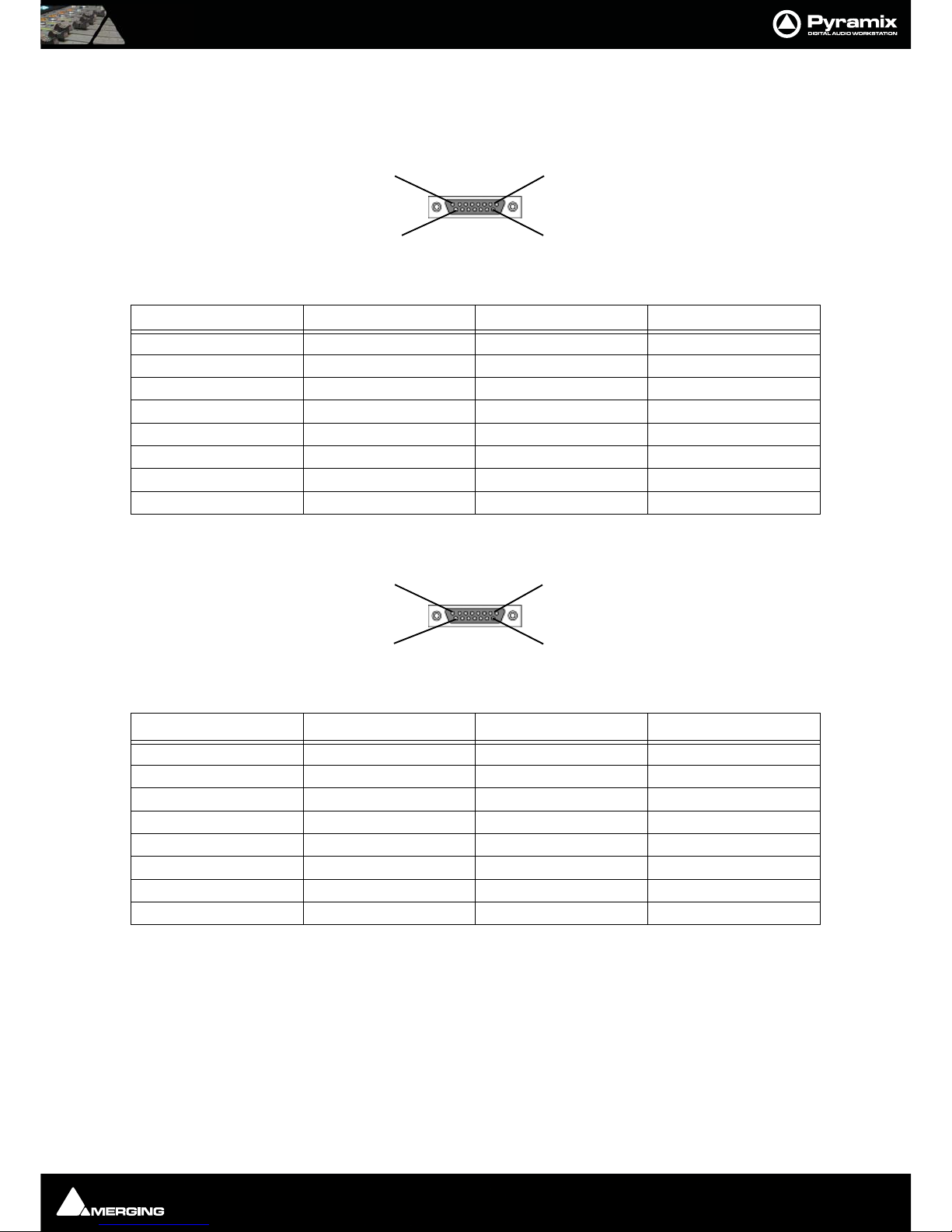
ISIS User Guide : Appendix III - Expansion Connector Pin-out
Page 50
Appendix III - Expansion Connector Pin-out
Main Unit rear panel connector
DB15 Female Connector
Fader Expansion Unit rear panel connector
DB15 Male Connector
Cable Specification
Maximum approved length: 1.5M
Cable Type: ALPHA CABLE, 7-PAIR, 24AWG, SCREENED.
Part number: 5477C-100
Note: Drain wire is connected to Pin 11 and must be insulated with sleeving.
Signal DB-15-F Signal DB-15-F
DC POWER OUT 1 DC POWER OUT 9
DC POWER OUT 2 DC POWER OUT 10
DC POWER OUT 3 GROUND 11
GROUND 4 GROUND 12
GROUND 5 RS232 RX2 13
RS232 TX2 6 GROUND 14
GROUND 7 RS232 RX1 15
RS232 TX1 8
Signal DB-15-M Signal DB-15-M
DC POWER IN 1 DC POWER IN 9
DC POWER IN 2 DCPOWER IN 10
DCPOWER IN 3 GROUND 11
GROUND 4 GROUND 12
GROUND 5 RS232 TX2 13
RS232 RX2 6 GROUND 14
GROUND 7 RS232 TX1 15
RS232 RX1 8
8
15
1
9
1
9
8
15
Page 51

ISIS User Guide : Appendix IV - Troubleshooting / FAQ
Page 51
Appendix IV - Troubleshooting / FAQ
ISIS not communicating with PC
If the ISIS does not appear to be communicating with Pyramix first check that ISIS is enabled in Settings > All Settings > Remote Control > Controller by selecting the ISIS entry in the list and clicking on Properties to open the
Controller Properties dialog. If the ISIS is not enabled, click the check box to enable it, click OK to close the dia-
log and click on Apply Changes to Controller to enable. If the ISIS does not respond, disable then re-enable it.
If the ISIS still fails to respond check that there is an IP address shown in the Selected Device: combo box of the
ISIS Configuration dialog and that the address is appropriate for your network configuration. If an IP address is
shown but is inappropriate then please see Setting the ISIS Static IP Address on page 15. If no IP address is
shown, check the physical connections and network topology.
Page 52

ISIS User Manual : Index
Page 52
ISIS User Manual : Index
A
Automation 28
C
Cable Specification 50
CE Notice 6
Channel Strip Functions 18
Checking IP Configuration 16
Checking Network Connections 16
Connections 9
Contact 7
Crossfade Editing 31
Crossfade Page 31
Crossfade Parameters 32
D
Default Configuration 18
Default mappings 29
Direct Access to LCD Pages 19
drivers 10
E
Edit 24
Expansion Connector Pin-out 50
EXPANSION Socket 10
F
FAQ 51
FCC Notice 6
First User page 21
Function Soft Keys 19
G
Global Shortcuts 20
I
Initial Configuration 11
Installation 9
Introduction 8
Invalid Mappings 27
ISIS Fader Expansion 30
ISIS Warranty 6
J
Jog Wheel 23
Jog Wheel Settings 25
L
LCD Contrast 17
LCD Display 19
LCD User Pages 27
LED Brightness 17
M
Machine Select page 21
Manual PC TC/IP Address Configuration 13
Mappable Functions 29, 33
Mapping Functions to ISIS Keys 26
Mapping Mixer Strips to ISIS Controller Strips 28
Master/Monitor Strip 28
Monitor page 22
N
Navigating LCD Pages 19
O
Overview 8
P
Positioning 9
Power Jack 10
Power up sequence 11
R
Removing a Mapping 27
RJ-45 Jack 10
S
Setting the ISIS Static IP Address 15
Software 10
Special Mappings 27
STATIC DANGER NOTICE 6
Page 53

ISIS User Manual : Index :
1 - 53
Static IP Address
15
Surface Labels 18
System Requirements 9
T
TC/IP Address Configuration 13
Technical Specifications 49
Tips and Tricks 29
Track Select Key Functions 20
Transport Control 23
U
User Configuration 26
User Mappings 29
User page (default) 21
V
Viewing the IP Address 16
W
Windows XP SP2 Firewall 13
Page 54

ISIS User Manual : Index : Index
Page 54
A
Automation 28
C
Cable Specification 50
CE Notice 6
Channel Strip Functions 18
Checking IP Configuration 16
Checking Network Connections 16
Connections 9
Contact 7
Crossfade Editing 31
Crossfade Page 31
Crossfade Parameters 32
D
Default Configuration 18
Default mappings 29
Direct Access to LCD Pages 19
drivers 10
E
Edit 24
Expansion Connector Pin-out 50
EXPANSION Socket 10
F
FAQ 51
FCC Notice 6
First User page 21
Function Soft Keys 19
G
Global Shortcuts 20
I
Initial Configuration 11
Installation 9
Introduction 8
Invalid Mappings 27
ISIS Fader Expansion 30
ISIS Warranty 6
J
Jog Wheel 23
Jog Wheel Settings 25
L
LCD Contrast 17
LCD Display 19
LCD User Pages 27
LED Brightness 17
M
Machine Select page 21
Manual PC TC/IP Address Configuration 13
Mappable Functions 29, 33
Mapping Functions to ISIS Keys 26
Mapping Mixer Strips to ISIS Controller Strips 28
Master/Monitor Strip 28
Monitor page 22
N
Navigating LCD Pages 19
O
Overview 8
P
Positioning 9
Power Jack 10
Power up sequence 11
R
Removing a Mapping 27
RJ-45 Jack 10
S
Setting the ISIS Static IP Address 15
Software 10
Special Mappings 27
STATIC DANGER NOTICE 6
Static IP Address 15
Surface Labels 18
System Requirements 9
T
TC/IP Address Configuration 13
Technical Specifications 49
Tips and Tricks 29
Track Select Key Functions 20
Transport Control 23
U
User Configuration 26
Index
Page 55

ISIS User Manual : Index : Index
Page 55
User Mappings 29
User page (default) 21
V
Viewing the IP Address 16
W
Windows XP SP2 Firewall 13
 Loading...