


User Guide
300Mbps Multi-Mode Wireless N Router
MW302R
REV1.0.0
1910080049

COPYRIGHT & TRADEMARK
Specications are subject to change without notice. is a registered
trademark of MERCUSYS TECHNOLOGIES CO., LTD. Other brands and product names are
trademarks or registered trademarks of their respective holders.
No part of the specications may be reproduced in any form or by any means or used to make
any derivative such as translation, transformation, or adaptation without permission from
MERCUSYS TECHNOLOGIES CO., LIMITED. Copyright © 2020 MERCUSYS TECHNOLOGIES
CO., LIMITED. All rights reserved.
http://www.mercusys.com

CE Mark Warning
This is a class B product. In a domestic environment, this product may cause radio interference,
in which case the user may be required to take adequate measures.
OPERATING FREQUENCY (the maximum transmitted power)
2400 MHz -2483.5 MHz(20dBm)
EU declaration of conformity
MERCUSYS hereby declares that the device is in compliance with the essential requirements and
other relevant provisions of directives 2014/53/EU, 2009/125/EC, 2011/65/EU and (EU)2015/863.
The original EU declaration of conformity may be found at http://www.mercusys.com/en/ce.
RF Exposure Information
This device meets the EU requirements (2014/53/EU Article 3.1a) on the limitation of exposure
of the general public to electromagnetic elds by way of health protection.
The device complies with RF specications when the device used at 20 cm from your body.
Продукт сертифіковано згідно с правилами системи УкрСЕПРО на відповідність
вимогам нормативних документів та вимогам, що передбачені чинними законодавчими
актами України.
Safety Information
Ǵ Keep the device away from water, re, humidity or hot environments.
Ǵ Do not attempt to disassemble, repair, or modify the device.
Ǵ Do not use damaged charger or USB cable to charge the device.
Ǵ Do not use any other chargers than those recommended.
Ǵ Do not use the device where wireless devices are not allowed.
Ǵ Adapter shall be installed near the equipment and shall be easily accessible.
Ǵ
Use only power supplies which are provided by manufacturer and in the original
packing of this product. If you have any questions, please don't hesitate to contact us.
Please read and follow the above safety information when operating the device. We cannot
guarantee that no accidents or damage will occur due to improper use of the device. Please
use this product with care and operate at your own risk.

NCC Notice
注意!
依據 低功率電波輻射性電機管理辦法
第十二條 經型式認證合格之低功率射頻電機,非經許可,公司、商號或使用者均不得擅自變更
頻率、加大功率或變更原設計之特性或功能。
第十四條 低功率射頻電機之使用不得影響飛航安全及干擾合法通信;經發現有干擾現象時,應
立即停用,並改善至無干擾時方得繼續使用。前項合法通信,指依電信規定作業之無線電信。
低功率射頻電機需忍受合法通信或工業、科學以及醫療用電波輻射性電機設備之干擾。
BSMI Notice
安全諮詢及注意事項
• 請使用原裝電源供應器或只能按照本產品注明的電源類型使用本產品。
• 清潔本產品之前請先拔掉電源線。請勿使用液體、噴霧清潔劑或濕布進行清潔。
• 注意防潮,請勿將水或其他液體潑灑到本產品上。
• 插槽與開口供通風使用,以確保本產品的操作可靠並防止過熱,請勿堵塞或覆蓋開口。
• 請勿將本產品置放於靠近熱源的地方。除非有正常的通風,否則不可放在密閉位置中。
• 請不要私自打開機殼,不要私自拆開機殼或自行維修,如產品有故障請與原廠或代理商聯繫。
限用物質含有情況標示聲明書
產品元件名
稱
鉛
Pb
鎘
Cd
PCB ○ ○ ○ ○ ○ ○
外殼
電源供應器
○ ○ ○ ○ ○ ○
— ○ ○ ○ ○ ○
備考 1. " 超出 0.1 wt %" 及 " 超出 0.01 wt %" 系指限用物質之百分比含量超出百
分比含量基準值。
備考 2. " ○ " 系指該項限用物質之百分比含量未超出百分比含量基準值。
備考 3. "—" 系指該項限用物質為排除項目。
限用物質及其化學符號
汞
Hg
六價鉻
CrVI
多溴聯苯
PBB
多溴二苯醚
PBDE

Explanation of the symbols on the product label
Symbol Explanation
Class II equipment
AC voltage
DC voltage
Polarity of output terminals
Indoor use only
Energy efficiency Marking
RECYCLING
This product bears the selective sorting symbol for Waste electrical and electronic equipment
(WEEE). This means that this product must be handled pursuant to European directive 2012/19/
EU in order to be recycled or dismantled to minimize its impact on the environment.
User has the choice to give his product to a competent recycling organization or to the retailer
when he buys a new electrical or electronic equipment.

Contents
Conventions . . . . . . . . . . . . . . . . . . . . . . . . . . . . . . . . . . . . . . . . . . . . . . . . . . . . . . . . . . . . . . .1
Chapter 1. Introduction . . . . . . . . . . . . . . . . . . . . . . . . . . . . . . . . . . . . . . . . . . . . . . . . . . .2
1. 1. Product Overview. . . . . . . . . . . . . . . . . . . . . . . . . . . . . . . . . . . . . . . . . . . . . . . . . . . . . . . . . . . . . . . . . . 2
1. 2. Product Appearance. . . . . . . . . . . . . . . . . . . . . . . . . . . . . . . . . . . . . . . . . . . . . . . . . . . . . . . . . . . . . . . 2
1. 2. 1. The Front Panel . . . . . . . . . . . . . . . . . . . . . . . . . . . . . . . . . . . . . . . . . . . . . . . . . . . . . . . . . . . . . 2
1. 2. 2. The Rear Panel . . . . . . . . . . . . . . . . . . . . . . . . . . . . . . . . . . . . . . . . . . . . . . . . . . . . . . . . . . . . . . 3
Chapter 2. Connect to the Internet . . . . . . . . . . . . . . . . . . . . . . . . . . . . . . . . . . . . . . . .4
2. 1. Position Your Router . . . . . . . . . . . . . . . . . . . . . . . . . . . . . . . . . . . . . . . . . . . . . . . . . . . . . . . . . . . . . . . 4
2. 2. Connect to the Internet . . . . . . . . . . . . . . . . . . . . . . . . . . . . . . . . . . . . . . . . . . . . . . . . . . . . . . . . . . . . 4
2. 2. 1. Wireless Router Mode . . . . . . . . . . . . . . . . . . . . . . . . . . . . . . . . . . . . . . . . . . . . . . . . . . . . . . . 4
2. 2. 2. Access Point Mode. . . . . . . . . . . . . . . . . . . . . . . . . . . . . . . . . . . . . . . . . . . . . . . . . . . . . . . . . . 6
2. 2. 3. Range Extender Mode. . . . . . . . . . . . . . . . . . . . . . . . . . . . . . . . . . . . . . . . . . . . . . . . . . . . . . . 7
2. 2. 4. WISP Mode . . . . . . . . . . . . . . . . . . . . . . . . . . . . . . . . . . . . . . . . . . . . . . . . . . . . . . . . . . . . . . . . . 9
Chapter 3. Log In to the Router . . . . . . . . . . . . . . . . . . . . . . . . . . . . . . . . . . . . . . . . . . 10
Chapter 4. Configure the Router in Wireless Router Mode . . . . . . . . . . . . . . . 11
4. 1. Operation Mode . . . . . . . . . . . . . . . . . . . . . . . . . . . . . . . . . . . . . . . . . . . . . . . . . . . . . . . . . . . . . . . . . .11
4. 2. Network . . . . . . . . . . . . . . . . . . . . . . . . . . . . . . . . . . . . . . . . . . . . . . . . . . . . . . . . . . . . . . . . . . . . . . . . . .13
4. 2. 1. Status. . . . . . . . . . . . . . . . . . . . . . . . . . . . . . . . . . . . . . . . . . . . . . . . . . . . . . . . . . . . . . . . . . . . . .13
4. 2. 2. Internet . . . . . . . . . . . . . . . . . . . . . . . . . . . . . . . . . . . . . . . . . . . . . . . . . . . . . . . . . . . . . . . . . . . .14
4. 2. 3. MAC Clone . . . . . . . . . . . . . . . . . . . . . . . . . . . . . . . . . . . . . . . . . . . . . . . . . . . . . . . . . . . . . . . . .21
4. 2. 4. LAN . . . . . . . . . . . . . . . . . . . . . . . . . . . . . . . . . . . . . . . . . . . . . . . . . . . . . . . . . . . . . . . . . . . . . . .22
4. 2. 5. IPTV/VLAN . . . . . . . . . . . . . . . . . . . . . . . . . . . . . . . . . . . . . . . . . . . . . . . . . . . . . . . . . . . . . . . . .22
4. 2. 6. DHCP Server. . . . . . . . . . . . . . . . . . . . . . . . . . . . . . . . . . . . . . . . . . . . . . . . . . . . . . . . . . . . . . .23
4. 2. 7. Dynamic DNS . . . . . . . . . . . . . . . . . . . . . . . . . . . . . . . . . . . . . . . . . . . . . . . . . . . . . . . . . . . . . .25
4. 2. 8. Static Routing. . . . . . . . . . . . . . . . . . . . . . . . . . . . . . . . . . . . . . . . . . . . . . . . . . . . . . . . . . . . . . 26
4. 3. Wireless . . . . . . . . . . . . . . . . . . . . . . . . . . . . . . . . . . . . . . . . . . . . . . . . . . . . . . . . . . . . . . . . . . . . . . . . . .27
4. 3. 1. Wireless Settings . . . . . . . . . . . . . . . . . . . . . . . . . . . . . . . . . . . . . . . . . . . . . . . . . . . . . . . . . .27
4. 3. 2. Guest Network . . . . . . . . . . . . . . . . . . . . . . . . . . . . . . . . . . . . . . . . . . . . . . . . . . . . . . . . . . . . .29
4. 3. 3. Wireless Schedule . . . . . . . . . . . . . . . . . . . . . . . . . . . . . . . . . . . . . . . . . . . . . . . . . . . . . . . . .30
4. 3. 4. WPS . . . . . . . . . . . . . . . . . . . . . . . . . . . . . . . . . . . . . . . . . . . . . . . . . . . . . . . . . . . . . . . . . . . . . . .31
4. 3. 5. Additional Settings . . . . . . . . . . . . . . . . . . . . . . . . . . . . . . . . . . . . . . . . . . . . . . . . . . . . . . . . .32

4. 4. NAT Forwarding. . . . . . . . . . . . . . . . . . . . . . . . . . . . . . . . . . . . . . . . . . . . . . . . . . . . . . . . . . . . . . . . . . .33
4. 4. 1. Port Forwarding . . . . . . . . . . . . . . . . . . . . . . . . . . . . . . . . . . . . . . . . . . . . . . . . . . . . . . . . . . . .34
4. 4. 2. Port Triggering . . . . . . . . . . . . . . . . . . . . . . . . . . . . . . . . . . . . . . . . . . . . . . . . . . . . . . . . . . . . .35
4. 4. 3. UPnP. . . . . . . . . . . . . . . . . . . . . . . . . . . . . . . . . . . . . . . . . . . . . . . . . . . . . . . . . . . . . . . . . . . . . . .36
4. 4. 4. DMZ . . . . . . . . . . . . . . . . . . . . . . . . . . . . . . . . . . . . . . . . . . . . . . . . . . . . . . . . . . . . . . . . . . . . . . .38
4. 5. Parental Controls . . . . . . . . . . . . . . . . . . . . . . . . . . . . . . . . . . . . . . . . . . . . . . . . . . . . . . . . . . . . . . . . .39
4. 6. QoS . . . . . . . . . . . . . . . . . . . . . . . . . . . . . . . . . . . . . . . . . . . . . . . . . . . . . . . . . . . . . . . . . . . . . . . . . . . . . .41
4. 7. Security . . . . . . . . . . . . . . . . . . . . . . . . . . . . . . . . . . . . . . . . . . . . . . . . . . . . . . . . . . . . . . . . . . . . . . . . . . 42
4. 7. 1. Firewall. . . . . . . . . . . . . . . . . . . . . . . . . . . . . . . . . . . . . . . . . . . . . . . . . . . . . . . . . . . . . . . . . . . . .42
4. 7. 2. Access Control. . . . . . . . . . . . . . . . . . . . . . . . . . . . . . . . . . . . . . . . . . . . . . . . . . . . . . . . . . . . .43
4. 7. 3. IP & MAC Binding. . . . . . . . . . . . . . . . . . . . . . . . . . . . . . . . . . . . . . . . . . . . . . . . . . . . . . . . . . . 45
4. 8. IPv6 . . . . . . . . . . . . . . . . . . . . . . . . . . . . . . . . . . . . . . . . . . . . . . . . . . . . . . . . . . . . . . . . . . . . . . . . . . . . . .46
4. 8. 1. IPv6 Status. . . . . . . . . . . . . . . . . . . . . . . . . . . . . . . . . . . . . . . . . . . . . . . . . . . . . . . . . . . . . . . . .46
4. 9. System . . . . . . . . . . . . . . . . . . . . . . . . . . . . . . . . . . . . . . . . . . . . . . . . . . . . . . . . . . . . . . . . . . . . . . . . . . .49
4. 9. 1. Firmware Upgrade. . . . . . . . . . . . . . . . . . . . . . . . . . . . . . . . . . . . . . . . . . . . . . . . . . . . . . . . . .49
4. 9. 2. Backup & Restore . . . . . . . . . . . . . . . . . . . . . . . . . . . . . . . . . . . . . . . . . . . . . . . . . . . . . . . . . .50
4. 9. 3. Change Password. . . . . . . . . . . . . . . . . . . . . . . . . . . . . . . . . . . . . . . . . . . . . . . . . . . . . . . . . .51
4. 9. 4. Local Management. . . . . . . . . . . . . . . . . . . . . . . . . . . . . . . . . . . . . . . . . . . . . . . . . . . . . . . . . 51
4. 9. 5. Remote Management . . . . . . . . . . . . . . . . . . . . . . . . . . . . . . . . . . . . . . . . . . . . . . . . . . . . . .52
4. 9. 6. System Log . . . . . . . . . . . . . . . . . . . . . . . . . . . . . . . . . . . . . . . . . . . . . . . . . . . . . . . . . . . . . . . . 54
4. 9. 7. Diagnostics . . . . . . . . . . . . . . . . . . . . . . . . . . . . . . . . . . . . . . . . . . . . . . . . . . . . . . . . . . . . . . . .55
4. 9. 8. Time . . . . . . . . . . . . . . . . . . . . . . . . . . . . . . . . . . . . . . . . . . . . . . . . . . . . . . . . . . . . . . . . . . . . . . . 56
4. 9. 9. Reboot . . . . . . . . . . . . . . . . . . . . . . . . . . . . . . . . . . . . . . . . . . . . . . . . . . . . . . . . . . . . . . . . . . . . . 58
4. 9. 10. LED Control. . . . . . . . . . . . . . . . . . . . . . . . . . . . . . . . . . . . . . . . . . . . . . . . . . . . . . . . . . . . . . . 58
Chapter 5. Configure the Router in Access Point Mode . . . . . . . . . . . . . . . . . . 60
5. 1. Operation Mode . . . . . . . . . . . . . . . . . . . . . . . . . . . . . . . . . . . . . . . . . . . . . . . . . . . . . . . . . . . . . . . . . .60
5. 2. Firmware Upgrade . . . . . . . . . . . . . . . . . . . . . . . . . . . . . . . . . . . . . . . . . . . . . . . . . . . . . . . . . . . . . . . .61
5. 2. 1. Backup & Restore . . . . . . . . . . . . . . . . . . . . . . . . . . . . . . . . . . . . . . . . . . . . . . . . . . . . . . . . . .62
5. 3. Administration. . . . . . . . . . . . . . . . . . . . . . . . . . . . . . . . . . . . . . . . . . . . . . . . . . . . . . . . . . . . . . . . . . . . 63
5. 3. 1. Change Password. . . . . . . . . . . . . . . . . . . . . . . . . . . . . . . . . . . . . . . . . . . . . . . . . . . . . . . . . .63
5. 3. 2. Local Management. . . . . . . . . . . . . . . . . . . . . . . . . . . . . . . . . . . . . . . . . . . . . . . . . . . . . . . . . 63
5. 3. 3. System Log . . . . . . . . . . . . . . . . . . . . . . . . . . . . . . . . . . . . . . . . . . . . . . . . . . . . . . . . . . . . . . . . 64
5. 4. Diagnostics. . . . . . . . . . . . . . . . . . . . . . . . . . . . . . . . . . . . . . . . . . . . . . . . . . . . . . . . . . . . . . . . . . . . . . .65
5. 4. 1. Time . . . . . . . . . . . . . . . . . . . . . . . . . . . . . . . . . . . . . . . . . . . . . . . . . . . . . . . . . . . . . . . . . . . . . . . 66
5. 5. Reboot . . . . . . . . . . . . . . . . . . . . . . . . . . . . . . . . . . . . . . . . . . . . . . . . . . . . . . . . . . . . . . . . . . . . . . . . . . .68
5. 6. LED Control . . . . . . . . . . . . . . . . . . . . . . . . . . . . . . . . . . . . . . . . . . . . . . . . . . . . . . . . . . . . . . . . . . . . . .68
Chapter 6. Configure the Router in Range Extender Mode . . . . . . . . . . . . . . . 70

6. 1. Operation Mode . . . . . . . . . . . . . . . . . . . . . . . . . . . . . . . . . . . . . . . . . . . . . . . . . . . . . . . . . . . . . . . . . .70
6. 2. Firmware Upgrade . . . . . . . . . . . . . . . . . . . . . . . . . . . . . . . . . . . . . . . . . . . . . . . . . . . . . . . . . . . . . . . .71
6. 3. Backup & Restore. . . . . . . . . . . . . . . . . . . . . . . . . . . . . . . . . . . . . . . . . . . . . . . . . . . . . . . . . . . . . . . . . 72
6. 4. Administration. . . . . . . . . . . . . . . . . . . . . . . . . . . . . . . . . . . . . . . . . . . . . . . . . . . . . . . . . . . . . . . . . . . . 73
6. 4. 1. Change Password. . . . . . . . . . . . . . . . . . . . . . . . . . . . . . . . . . . . . . . . . . . . . . . . . . . . . . . . . .73
6. 4. 2. Local Management. . . . . . . . . . . . . . . . . . . . . . . . . . . . . . . . . . . . . . . . . . . . . . . . . . . . . . . . . 73
6. 5. System Log. . . . . . . . . . . . . . . . . . . . . . . . . . . . . . . . . . . . . . . . . . . . . . . . . . . . . . . . . . . . . . . . . . . . . . .74
6. 5. 1. Time . . . . . . . . . . . . . . . . . . . . . . . . . . . . . . . . . . . . . . . . . . . . . . . . . . . . . . . . . . . . . . . . . . . . . . . 75
6. 6. Reboot . . . . . . . . . . . . . . . . . . . . . . . . . . . . . . . . . . . . . . . . . . . . . . . . . . . . . . . . . . . . . . . . . . . . . . . . . . .76
6. 7. LED Control . . . . . . . . . . . . . . . . . . . . . . . . . . . . . . . . . . . . . . . . . . . . . . . . . . . . . . . . . . . . . . . . . . . . . .77
Chapter 7. Configure the Router in WISP Mode . . . . . . . . . . . . . . . . . . . . . . . . . . 79
7. 1. Operation Mode . . . . . . . . . . . . . . . . . . . . . . . . . . . . . . . . . . . . . . . . . . . . . . . . . . . . . . . . . . . . . . . . . .79
7. 2. Network . . . . . . . . . . . . . . . . . . . . . . . . . . . . . . . . . . . . . . . . . . . . . . . . . . . . . . . . . . . . . . . . . . . . . . . . . .80
7. 2. 1. Status. . . . . . . . . . . . . . . . . . . . . . . . . . . . . . . . . . . . . . . . . . . . . . . . . . . . . . . . . . . . . . . . . . . . . .80
7. 2. 2. Internet . . . . . . . . . . . . . . . . . . . . . . . . . . . . . . . . . . . . . . . . . . . . . . . . . . . . . . . . . . . . . . . . . . . .82
7. 2. 3. MAC Clone . . . . . . . . . . . . . . . . . . . . . . . . . . . . . . . . . . . . . . . . . . . . . . . . . . . . . . . . . . . . . . . . . 89
7. 2. 4. LAN . . . . . . . . . . . . . . . . . . . . . . . . . . . . . . . . . . . . . . . . . . . . . . . . . . . . . . . . . . . . . . . . . . . . . . .90
7. 2. 5. DHCP Server . . . . . . . . . . . . . . . . . . . . . . . . . . . . . . . . . . . . . . . . . . . . . . . . . . . . . . . . . . . . . . .90
7. 2. 6. Dynamic DNS . . . . . . . . . . . . . . . . . . . . . . . . . . . . . . . . . . . . . . . . . . . . . . . . . . . . . . . . . . . . . .92
7. 2. 7. Static Routing . . . . . . . . . . . . . . . . . . . . . . . . . . . . . . . . . . . . . . . . . . . . . . . . . . . . . . . . . . . . . .93
7. 3. Wireless . . . . . . . . . . . . . . . . . . . . . . . . . . . . . . . . . . . . . . . . . . . . . . . . . . . . . . . . . . . . . . . . . . . . . . . . . .95
7. 3. 1. Wireless Settings . . . . . . . . . . . . . . . . . . . . . . . . . . . . . . . . . . . . . . . . . . . . . . . . . . . . . . . . . .95
7. 3. 2. Guest Network . . . . . . . . . . . . . . . . . . . . . . . . . . . . . . . . . . . . . . . . . . . . . . . . . . . . . . . . . . . . .96
7. 3. 3. Wireless Schedule . . . . . . . . . . . . . . . . . . . . . . . . . . . . . . . . . . . . . . . . . . . . . . . . . . . . . . . . .97
7. 3. 4. WPS . . . . . . . . . . . . . . . . . . . . . . . . . . . . . . . . . . . . . . . . . . . . . . . . . . . . . . . . . . . . . . . . . . . . . . .98
7. 3. 5. Additional Settings . . . . . . . . . . . . . . . . . . . . . . . . . . . . . . . . . . . . . . . . . . . . . . . . . . . . . . . 100
7. 4. NAT Forwarding. . . . . . . . . . . . . . . . . . . . . . . . . . . . . . . . . . . . . . . . . . . . . . . . . . . . . . . . . . . . . . . . . 101
7. 4. 1. Port Forwarding . . . . . . . . . . . . . . . . . . . . . . . . . . . . . . . . . . . . . . . . . . . . . . . . . . . . . . . . . . 101
7. 4. 2. Port Triggering . . . . . . . . . . . . . . . . . . . . . . . . . . . . . . . . . . . . . . . . . . . . . . . . . . . . . . . . . . . 103
7. 4. 3. UPnP . . . . . . . . . . . . . . . . . . . . . . . . . . . . . . . . . . . . . . . . . . . . . . . . . . . . . . . . . . . . . . . . . . . . 104
7. 4. 4. DMZ . . . . . . . . . . . . . . . . . . . . . . . . . . . . . . . . . . . . . . . . . . . . . . . . . . . . . . . . . . . . . . . . . . . . . 105
7. 5. Parental Controls . . . . . . . . . . . . . . . . . . . . . . . . . . . . . . . . . . . . . . . . . . . . . . . . . . . . . . . . . . . . . . . 106
7. 6. QoS . . . . . . . . . . . . . . . . . . . . . . . . . . . . . . . . . . . . . . . . . . . . . . . . . . . . . . . . . . . . . . . . . . . . . . . . . . . . 109
7. 7. Security . . . . . . . . . . . . . . . . . . . . . . . . . . . . . . . . . . . . . . . . . . . . . . . . . . . . . . . . . . . . . . . . . . . . . . . . 110
7. 7. 1. Firewall. . . . . . . . . . . . . . . . . . . . . . . . . . . . . . . . . . . . . . . . . . . . . . . . . . . . . . . . . . . . . . . . . . . 110
7. 7. 2. Access Control. . . . . . . . . . . . . . . . . . . . . . . . . . . . . . . . . . . . . . . . . . . . . . . . . . . . . . . . . . . 110
7. 7. 3. IP & MAC Binding. . . . . . . . . . . . . . . . . . . . . . . . . . . . . . . . . . . . . . . . . . . . . . . . . . . . . . . . . 112
7. 8. IPv6 . . . . . . . . . . . . . . . . . . . . . . . . . . . . . . . . . . . . . . . . . . . . . . . . . . . . . . . . . . . . . . . . . . . . . . . . . . . . 114

7. 8. 1. IPv6 Status. . . . . . . . . . . . . . . . . . . . . . . . . . . . . . . . . . . . . . . . . . . . . . . . . . . . . . . . . . . . . . . 114
7. 9. System . . . . . . . . . . . . . . . . . . . . . . . . . . . . . . . . . . . . . . . . . . . . . . . . . . . . . . . . . . . . . . . . . . . . . . . . . 117
7. 9. 1. Firmware Upgrade. . . . . . . . . . . . . . . . . . . . . . . . . . . . . . . . . . . . . . . . . . . . . . . . . . . . . . . . 117
7. 9. 2. Backup & Restore . . . . . . . . . . . . . . . . . . . . . . . . . . . . . . . . . . . . . . . . . . . . . . . . . . . . . . . . 117
7. 9. 3. Change Password. . . . . . . . . . . . . . . . . . . . . . . . . . . . . . . . . . . . . . . . . . . . . . . . . . . . . . . . 118
7. 9. 4. Local Management. . . . . . . . . . . . . . . . . . . . . . . . . . . . . . . . . . . . . . . . . . . . . . . . . . . . . . . 119
7. 9. 5. Remote Management . . . . . . . . . . . . . . . . . . . . . . . . . . . . . . . . . . . . . . . . . . . . . . . . . . . . 120
7. 9. 6. System Log . . . . . . . . . . . . . . . . . . . . . . . . . . . . . . . . . . . . . . . . . . . . . . . . . . . . . . . . . . . . . . 121
7. 9. 7. Diagnostics . . . . . . . . . . . . . . . . . . . . . . . . . . . . . . . . . . . . . . . . . . . . . . . . . . . . . . . . . . . . . . 122
7. 9. 8. Time . . . . . . . . . . . . . . . . . . . . . . . . . . . . . . . . . . . . . . . . . . . . . . . . . . . . . . . . . . . . . . . . . . . . . 123
7. 9. 9. Reboot . . . . . . . . . . . . . . . . . . . . . . . . . . . . . . . . . . . . . . . . . . . . . . . . . . . . . . . . . . . . . . . . . . . 125
7. 9. 10. LED Control. . . . . . . . . . . . . . . . . . . . . . . . . . . . . . . . . . . . . . . . . . . . . . . . . . . . . . . . . . . . . 125
Appendix: FAQ (Frequently Asked Questions) . . . . . . . . . . . . . . . . . . . . . . . . . . . 127

Conventions
The router or MW302R, or device mentioned in this User Guide stands for MW302R
300Mbps Multi-Mode Wireless N Router without any explanations.
Features available in the router may vary by model and software version. Router availability
may also vary by region or ISP. All images, steps, and descriptions in this guide are only
examples and may not reflect your actual router experience.
More Info
Specifications and the latest software can be found at the product page at the official
website http://www.mercusys.com.
The Quick Installation Guide can be found where you find this guide or inside the package
of the router.
Speed/Coverage Disclaimer
*Maximum wireless signal rates are the physical rates derived from IEEE Standard 802.11
specifications. Actual wireless data throughput and wireless coverage are not guaranteed
and will vary as a result of 1) environmental factors, including building materials, physical
objects, and obstacles, 2) network conditions, including local interference, volume and
density of traffic, product location, network complexity, and network overhead, and 3) client
limitations, including rated performance, location, connection, quality, and client condition.
1
Chapter 1
Chapter 1. Introduction
1. 1. Product Overview
The router integrates 3-port Switch, Firewall, NAT-Router and Wireless AP. Powered by 2x2
MIMO technology, the router delivers exceptional range and speed, which can fully meet
the need of Small Office/Home Office (SOHO) networks and the users demanding higher
networking performance.
1. 2. Product Appearance
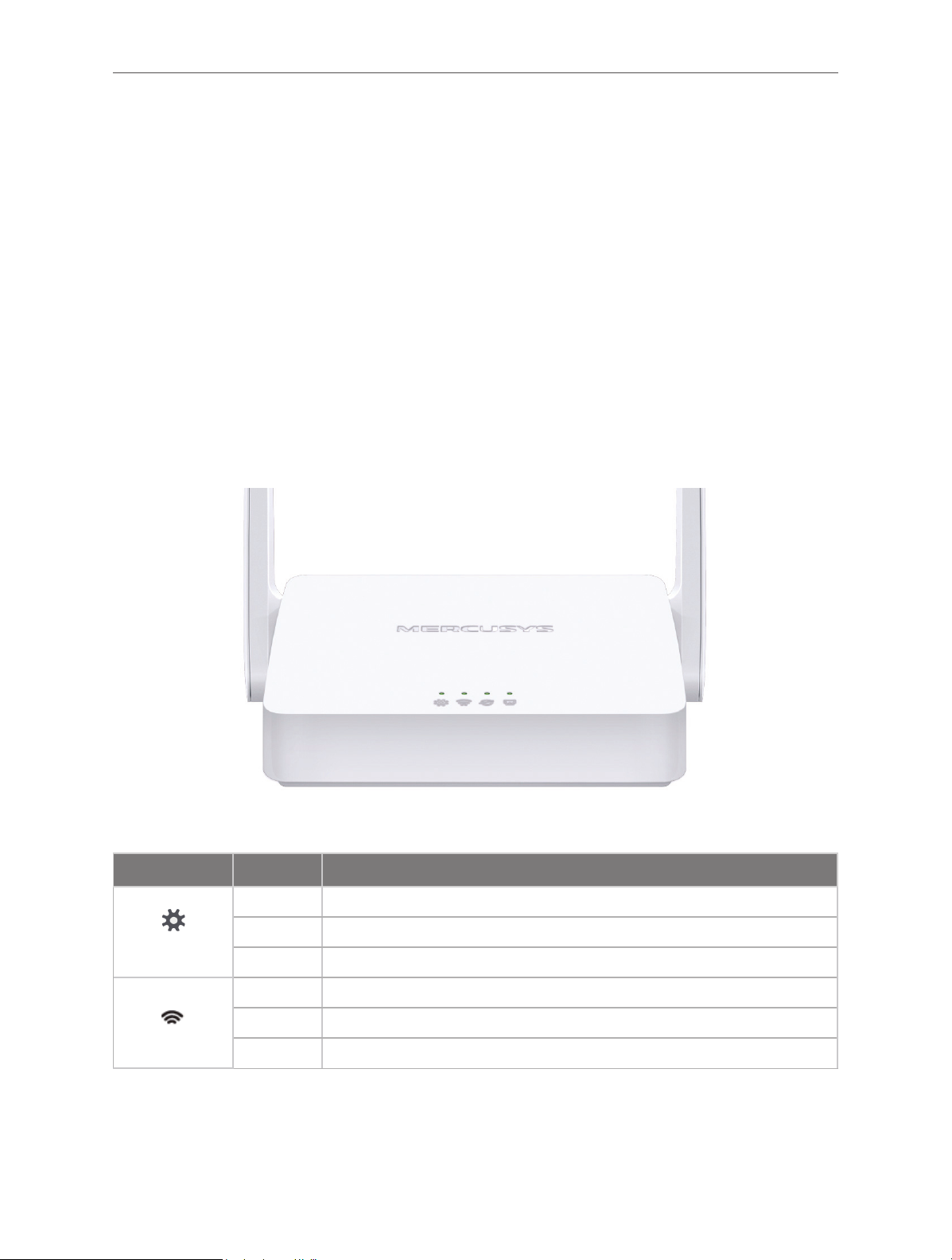
1. 2. 1. The Front Panel
The router’s LEDs are located on the front panel (View from left to right).
Name Status Indication
Off Power is off.
(SYS)
(WIFI)
Flashing The system is starting up or firmware is being upgraded*.
On Power is on.
Off The Wireless function is disabled.
Flashing WPS connection is in progress. This may take up to 2 minutes.
On The Wireless function is enabled.
2
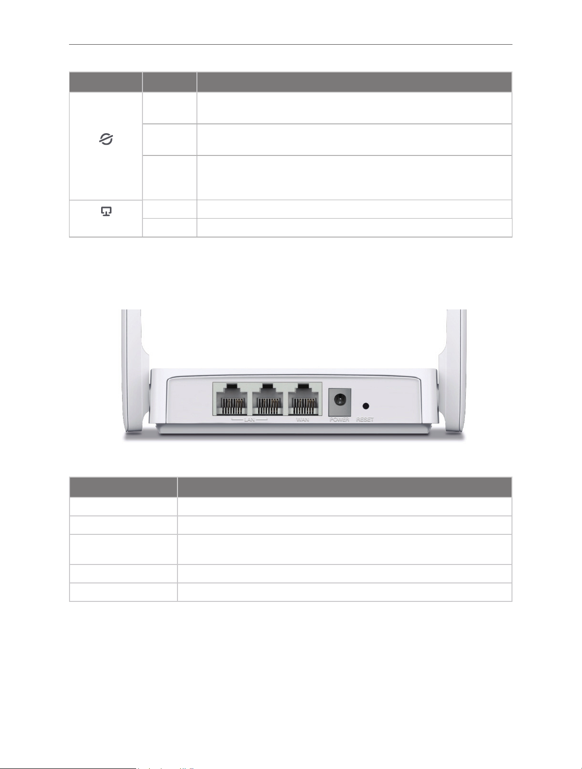
Name Status Indication
Chapter 1
Off
Flashing
(WAN)
On
Off Neither LAN port is connected.
(LAN)
* To avoid device damage, do not disconnect or power off your router during upgrade.
On At least one LAN port is connected.
Router Mode/Access Point Mode: The WAN port is not connected.
Range Extender/WISP Mode: The router is not connected to the host network.
Router Mode: The WAN port is connected, but internet is not available.
WISP Mode: Internet is not available.
Router/WISP Mode: Internet is available.
Access Point Mode: The WAN port is connected.
Range Extender Mode: The router is connected to the host network.
1. 2. 2. The Rear Panel
The following items are located on the rear panel (View from left to right).
Item Description
LAN Ports These ports connect the router to the local devices.
WAN Port This port is where you will connect the router to the DSL/cable Modem, or Ethernet.
POWER Socket
RESET Button Press and hold this button for more than 5 seconds to reset the router.
Wireless Antennas To receive and transmit the wireless data.
The power socket is where you will connect the power adapter. Please use the
power adapter provided with this router.
3

Chapter 2
Chapter 2. Connect to the Internet
2. 1. Position Your Router
• The product should not be located in a place where it will be exposed to moisture or
excessive heat.
• Place the router in a location where it can be connected to multiple devices as well as to
a power source.
• Make sure the cables and power cord are safely placed out of the way so they do not
create a tripping hazard.
• The router can be placed on a shelf or desktop.
• Keep the router away from devices with strong electromagnetic reference, such as
Bluetooth devices, cordless phones and microwaves.
Generally, the router is placed on a horizontal surface, such as on a shelf or desktop. The
device also can be mounted on the wall as shown in the following figure.
Note:
The diameter of the screw head, 4mm<D<7.5mm, and the distance of two screws is 58.5mm. The screw that project from the
wall need around 3.5mm based, and the length of the screw need to be at least 20mm to withstand the weight of the product.
2. 2. Connect to the Internet
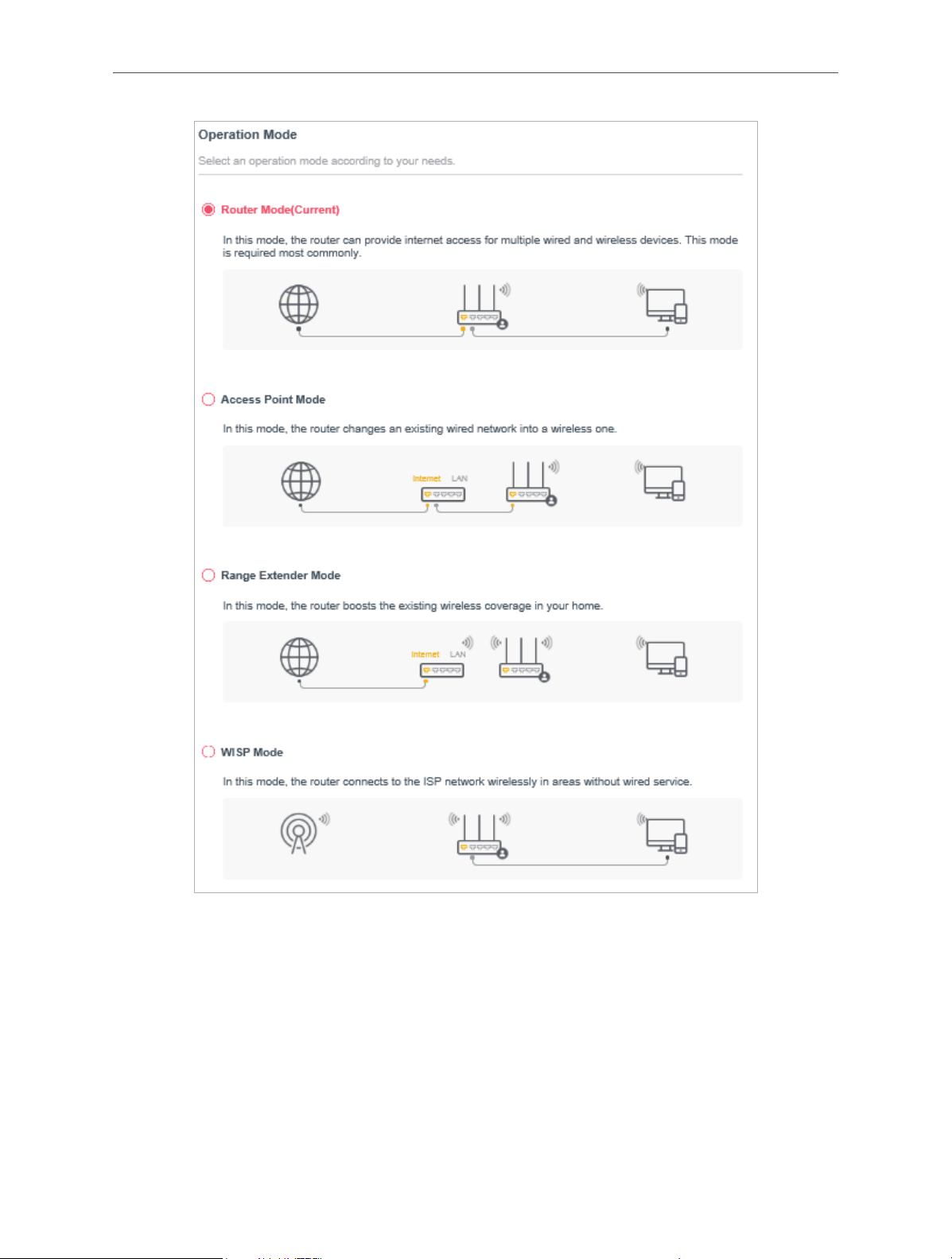
The Router provides four working modes: Wireless Router, Access Point, Range Extender
and WISP. You can choose the mode to better suit your network needs and follow the guide
to complete the configuration.
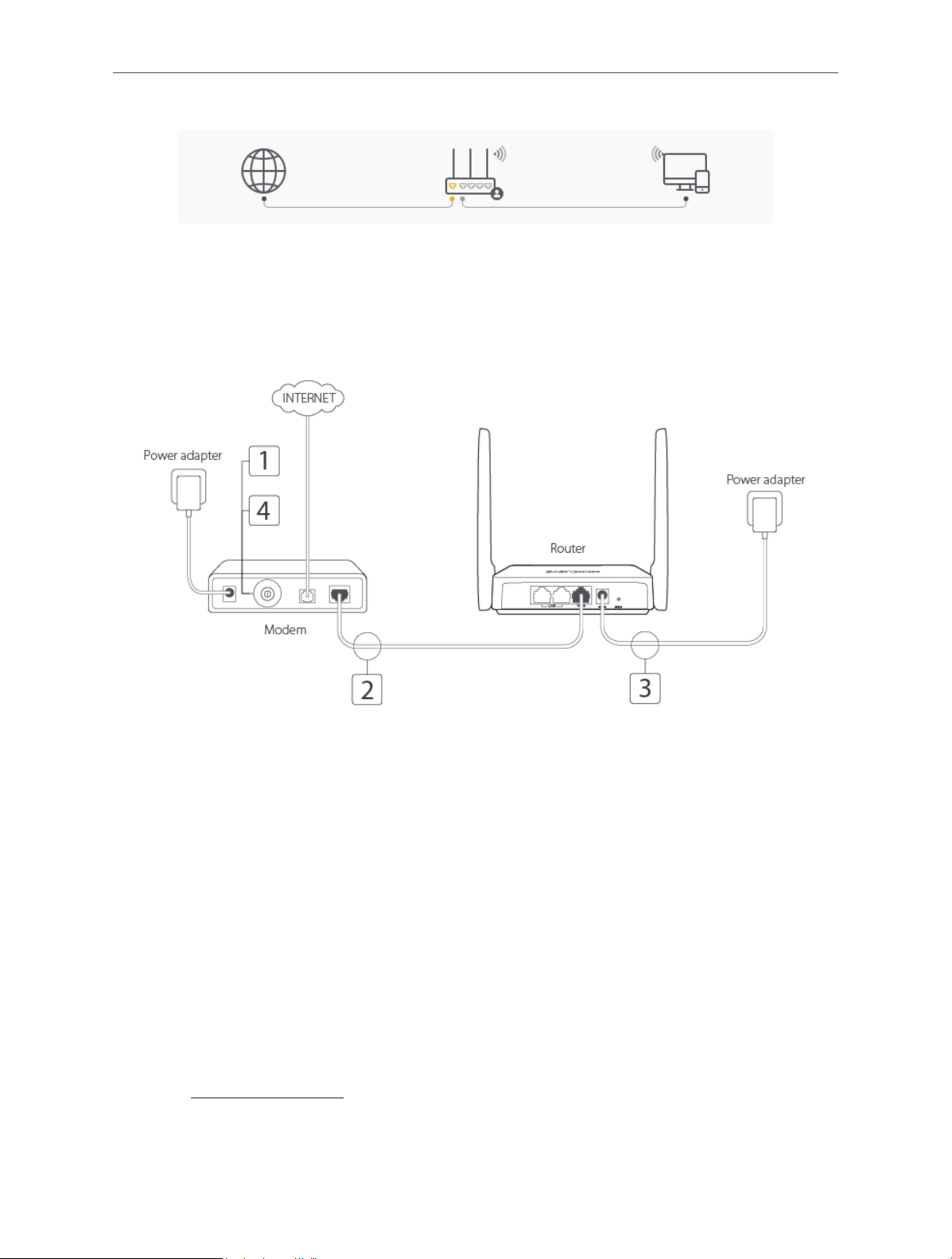
2. 2. 1. Wireless Router Mode
In this mode, the router can provide internet access for multiple wired and wireless devices.
This mode is required most commonly.
4
Chapter 2
1. Follow the steps below to connect your router.
If your Internet connection is through an Ethernet cable from the wall instead of through a
DSL/Cable/Satellite modem, connect the Ethernet cable directly to the router’s Internet port,
then follow steps 4 and 5 to complete the hardware connection.
1 ) Turn off the modem, and remove the backup battery if it has one.
2 ) Connect the modem to the router’s WAN port with an Ethernet cable.
3 ) Turn on the modem, and then wait about 2 minutes for it to restart.
4 ) Connect the power adapter to the router.
2. Connect your computer to the router.
• Method 1: Wired
Turn off the Wi-Fi on your computer and connect the devices as shown below.
• Method 2: Wirelessly
1 ) Find the SSID (Network Name) printed on the label at the bottom of the router.
2 ) Click the network icon of your computer or go to Wi-Fi Settings of your smart device,
and then select the SSID to join the network.
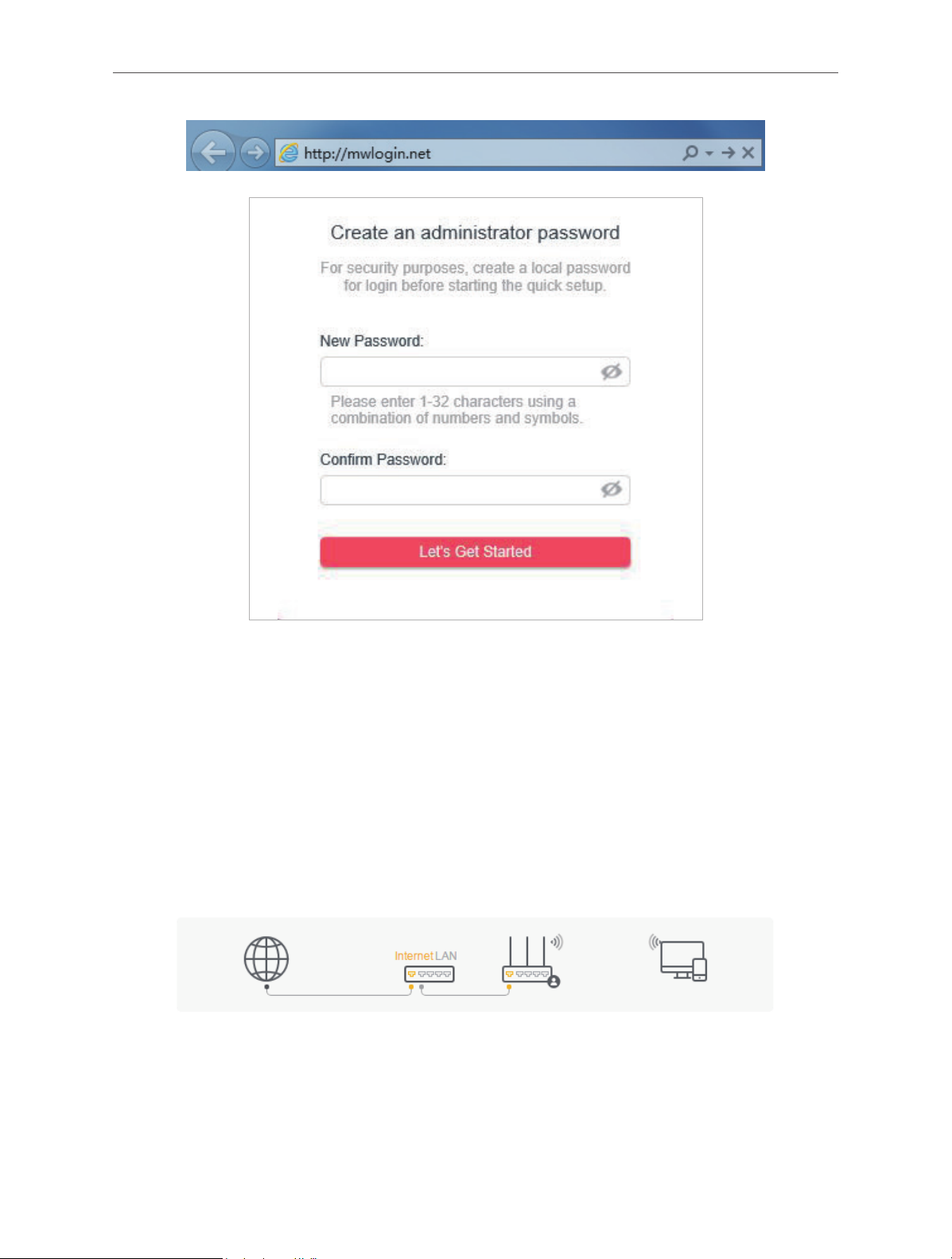
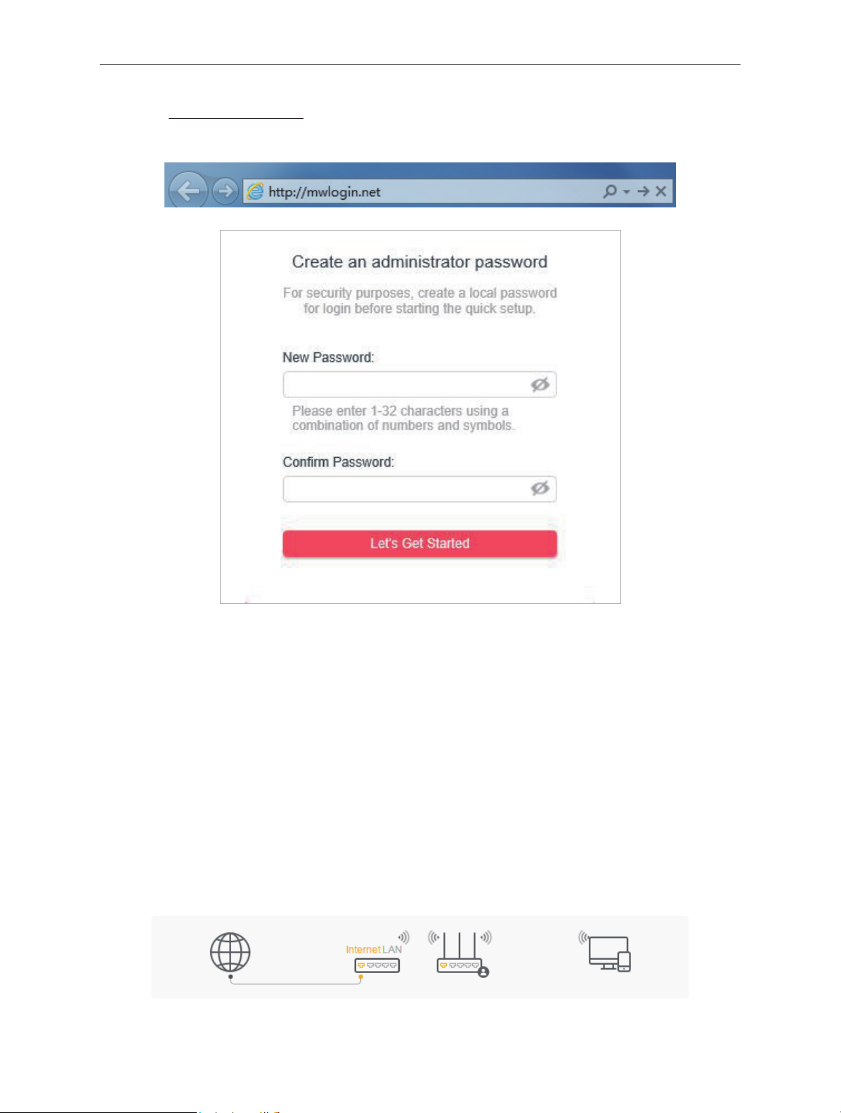
3. Enter http://mwlogin.net in the address bar of a web browser. Create a password to log
in.
5
Chapter 2
Note:
If the above screen does not pop-up, it means that your IE Web-browser has been set to a proxy. Go to menu Tools >
Internet Options > Connections > LAN Settings, in the screen that appears, untick the Using Proxy checkbox, and click
OK.
4. Follow the Quick Setup to set up the internet connection.
5. Enjoy! For wireless devices, you may have to reconnect to the wireless network if you
have customized the SSID (wireless name) and password during the configuration.
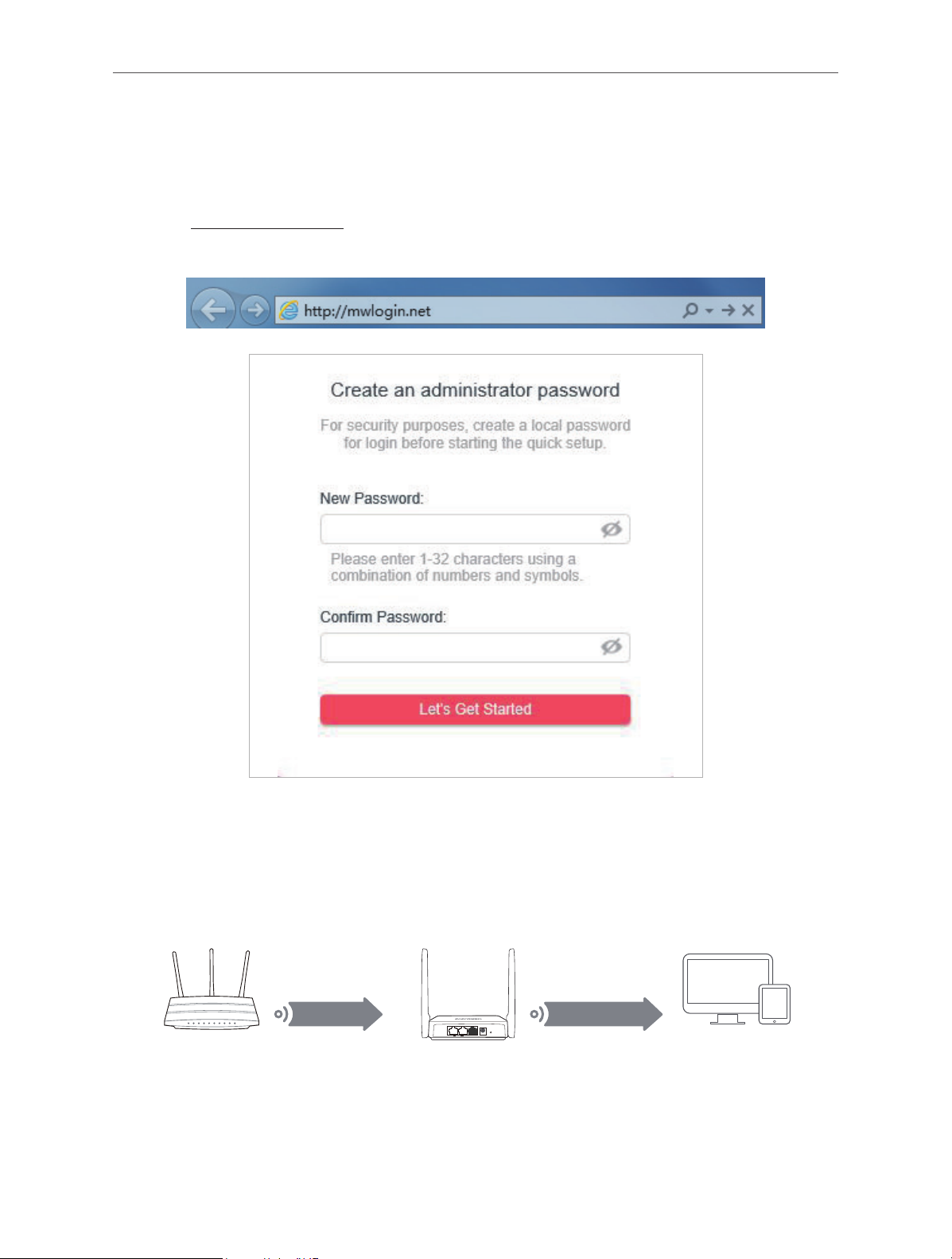
2. 2. 2. Access Point Mode
In this mode, the router changes an existing wired network into a wireless one.
1. Connect the power adapter to the router.
2. Connect the router’s WAN port (recommended) to your wired host router’s LAN port via
an Ethernet cable as shown above.
3. Connect a computer to the router via an Ethernet cable or wirelessly by using the SSID
(network name) printed on the bottom label of the router.
6
Chapter 2
4. Enter http://mwlogin.net in the address bar of a web browser. Create a password to log
in.
Note:
If the above screen does not pop-up, it means that your IE Web-browser has been set to a proxy. Go to menu Tools >
Internet Options > Connections > LAN Settings, in the screen that appears, untick the Using Proxy checkbox, and click OK.
5. Click Change Mode in the top right corner and select Access Point Mode. Wait for the
router to reboot.
6. Follow the Quick Setup to set up the internet connection.
7. Enjoy! Connect to the wireless network by using the SSID (network name) and password
of the router.
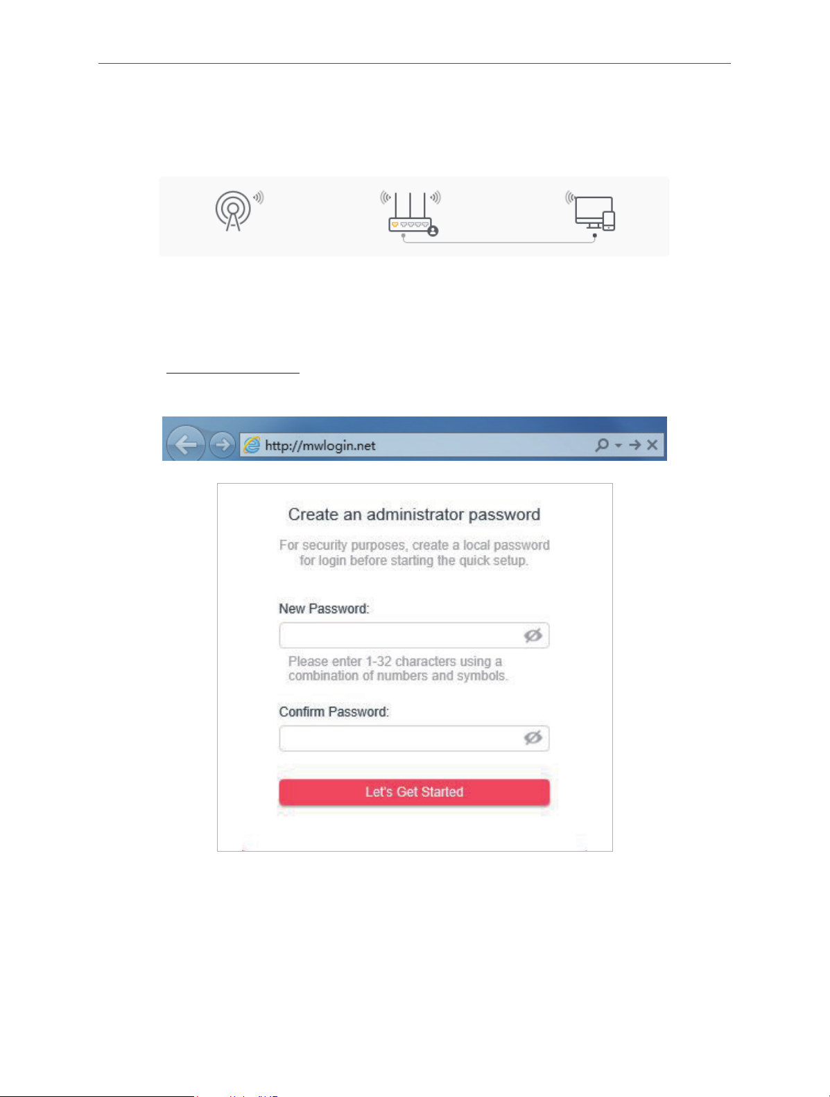
2. 2. 3. Range Extender Mode
In this mode, the router boosts the existing wireless coverage in your home.
7
Chapter 2
DevicesHost Router Router
1. Connect the power adapter to the router.
2. Connect a computer to the router via an Ethernet cable or wirelessly by using the SSID
(wireless name) printed on the bottom label of the router.
3. Enter http://mwlogin.net in the address bar of a web browser. Create a password to log
in.
4. Click Change Mode in the top right corner and select Range Extender Mode. Wait for
the router to reboot.
5. Follow the Quick Setup to set up the internet connection.
6. Relocate: Place the router between your host router and the Wi-Fi dead zone. The location
you choose must be within the range of your existing host network.
Extended NetworkHost Network
LAN WAN
POWER
RESET
7. Enjoy! You can customize the SSID and password of the extended network.
8
Chapter 2
2. 2. 4. WISP Mode
In this mode, the router connects to the ISP network wirelessly in areas without wired service.
1. Connect the power adapter to the router and power on the router.
2. Connect a computer to the router via an Ethernet cable or wirelessly by using the SSID
(wireless name) printed on the bottom label of the router.
3. Enter http://mwlogin.net in the address bar of a web browser. Create a password to log
in.
4. Click Change Mode in the top right corner and select WISP Mode. Wait for the router to
reboot.
5. Follow the Quick Setup to set up the internet connection.
6. Enjoy! Connect your devices to the wireless network and enjoy the internet.
9
Chapter 3
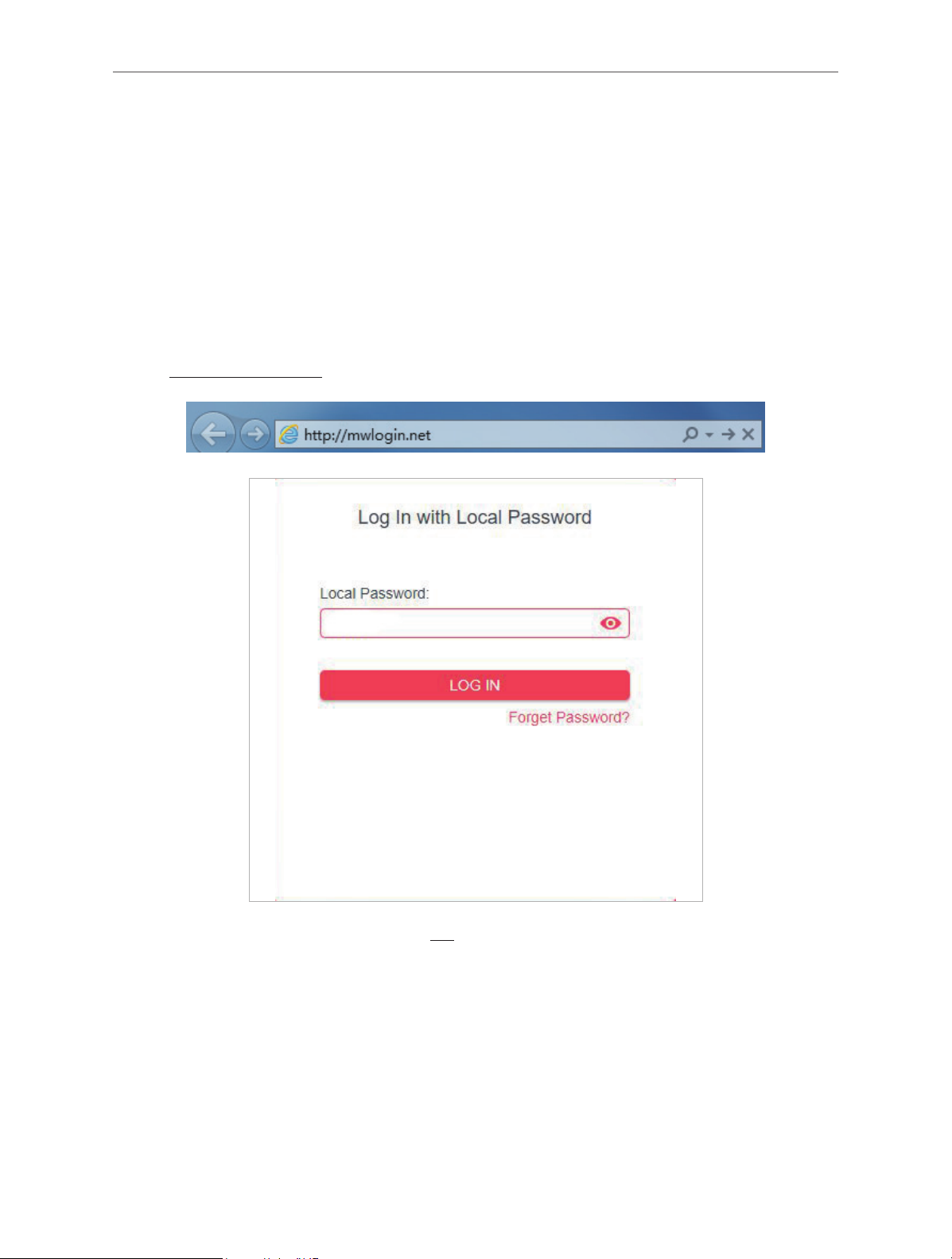
Chapter 3. Log In to the Router
This chapter introduces how to log in to the web management page of the router.
With the web-based utility, it is easy to configure and manage the router. The web-based utility
can be used on any Windows, Macintosh or UNIX OS with a Web browser, such as Microsoft
the Internet Explorer, Mozilla Firefox or Apple Safari.
Follow the steps below to log in to your router.
1. Set up the TCP/IP Protocol in Obtain an IP address automatically mode on your computer.
2. Visit http://mwlogin.net, and log in with the password you set for the router.
Note:
If the login window does not appear, please refer to the FAQ section.
10

Chapter 4
Chapter 4. Congure the Router in
Wireless Router Mode
This chapter presents how to configure the various features of the router working as a
wireless router.
It contains the following sections:
• Operation Mode
• Network
• Wireless
• NAT Forwarding
• Parental Controls
• QoS
• Security
• IPv6
• System
4. 1. Operation Mode
1. Visit http://mwlogin.net, and log in with the password you set for the router.
2. Go to Advanced > Operation Mode.
3. Select the working mode as needed and click SAVE.
11
Chapter 4
12
Chapter 4
4. 2. Network
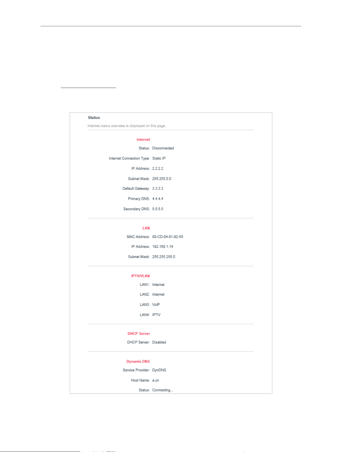
4. 2. 1. Status
1. Visit http://mwlogin.net, and log in with password you set for the router.
2. Go to Advanced > Network > Status. You can view the current status information of the
router.
• Internet - This field displays the current settings of the internet, and you can configure
them on the Advanced > Network > Internet page.
13

Chapter 4
• Status - Indicates whether the router has been connected to the internet.
• Internet Connection Type - Indicates the way in which your router is connected to
the internet.
• IP Address - The WAN IP address of the router.
• Subnet Mask - The subnet mask associated with the WAN IP address.
• Default Gateway - The Gateway currently used is shown here. When you use
Dynamic IP as the internet connection type, click Renew or Release here to obtain
new IP parameters dynamically from the ISP or release them.
• Primary & Secondary DNS - The IP addresses of DNS (Domain Name System)
server.
• LAN - This field displays the current settings of the LAN, and you can configure them on
the Advanced > Network > LAN page.
• MAC Address - The physical address of the router.
• IP Address - The LAN IP address of the router.
• Subnet Mask - The subnet mask associated with the LAN IP address.
• DHCP Server - This field displays the current settings of DHCP (Dynamic Host
Configuration Protocol) Server, and you can configure them on the Network > DHCP
Server page.
• DHCP Server - Indicates whether the DHCP server is enabled of disabled. It is
enabled by default and the router acts as a DHCP server.
• IP Address Pool - The IP address range for the DHCP server to assign IP addresses.
• Dynamic DNS - This field displays the current settings of the Dynamic DNS (Domain
Name System), and you can configure them on the Advanced > Network > Dynamic DNS
page.
• Service Provider - The Dynamic DNS service provider you have signed up for.
• Host Name - The Domain Name you have entered in the Dynamic DNS page.
• Status - The status of the Dynamic DNS service connection.
4. 2. 2. Internet
1. Visit http://mwlogin.net, and log in with the password you set for the router.
2. Go to Advanced > Network > Internet.
3. Set up the internet connection and click SAVE.
Dynamic IP
If your ISP provides the DHCP service, please select Dynamic IP, and the router will
automatically get IP parameters from your ISP.
Click RENEW to renew the IP parameters from your ISP.
14
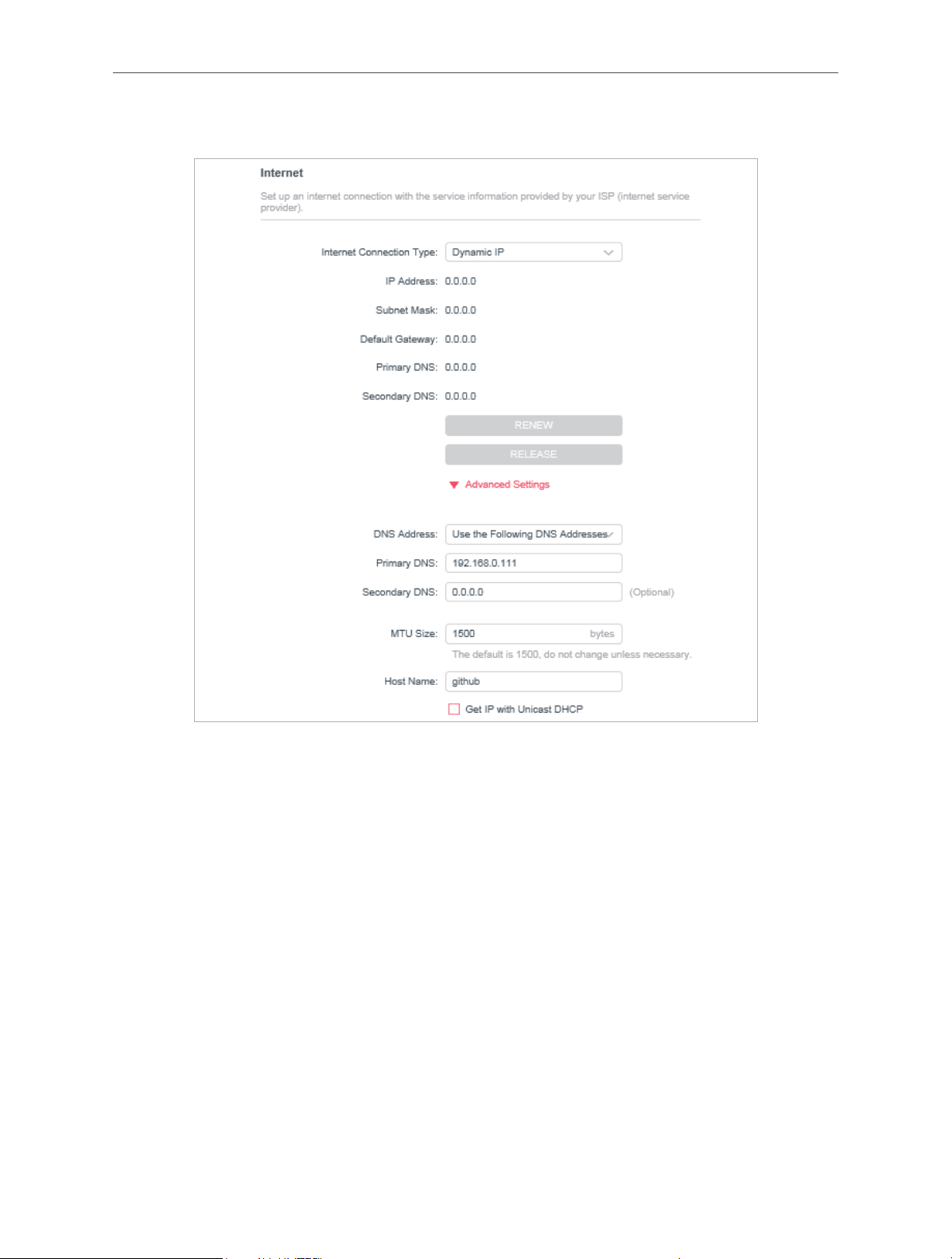
Click RELEASE to release the IP parameters.
Chapter 4
• MTU Size - The normal MTU (Maximum Transmission Unit) value for most Ethernet
networks is 1500 Bytes. It is not recommended that you change the default MTU size
unless required by your ISP.
• Host Name - This option specifies the name of the router.
• Get IP with Unicast DHCP - A few ISPs’ DHCP servers do support the broadcast applications. If
you cannot get the IP address normally, you can choose this option (it is rarely required).
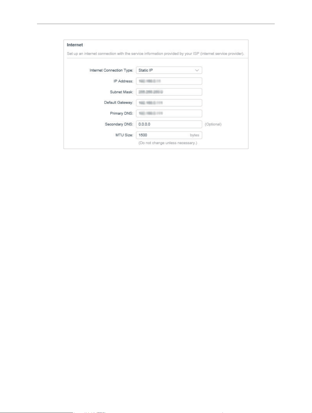
Static IP
If your ISP provides a static or fixed IP address, subnet mask, default gateway and DNS
setting, please select Static IP.
15
Chapter 4
• IP Address - Enter the IP address in dotted-decimal notation provided by your ISP.
• Subnet Mask - Enter the subnet mask in dotted-decimal notation provided by your ISP.
Normally 255.255.255.0 is used as the subnet mask.
• Default Gateway - Enter the gateway IP address in dotted-decimal notation provided by
your ISP.
• Primary/Secondary DNS - (Optional) Enter one or two DNS addresses in dotted-decimal
notation provided by your ISP.
• MTU Size - The normal MTU (Maximum Transmission Unit) value for most Ethernet
networks is 1500 bytes. It is not recommended that you change the default MTU size
unless required by your ISP.
PPPoE
If your ISP provides PPPoE connection, select PPPoE.
16
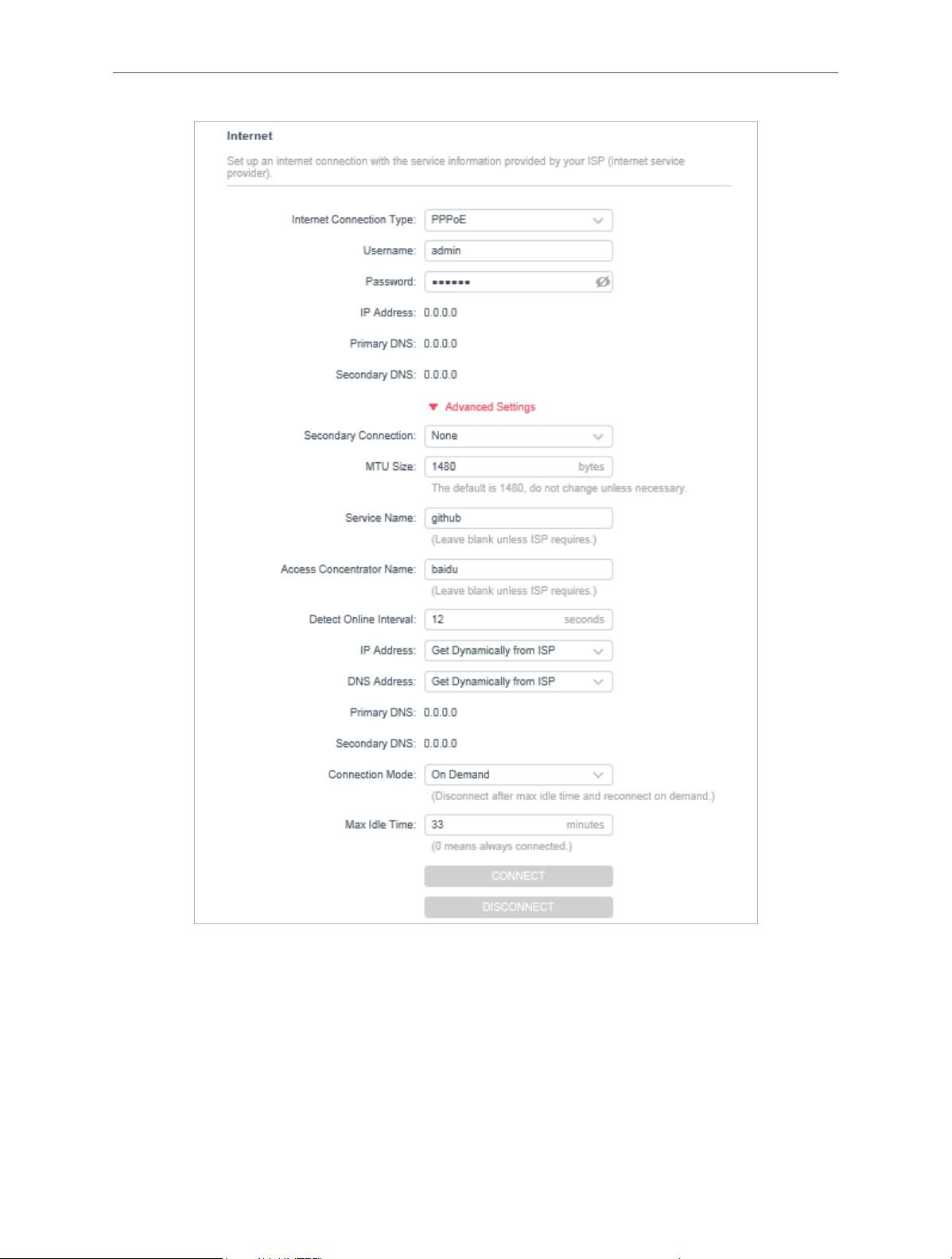
Chapter 4
• Username/Password - Enter the user name and password provided by your ISP. These
fields are case-sensitive.
• Secondary Connection - It’s available only for PPPoE connection. If your ISP provides
an extra connection type, select Dynamic IP or Static IP to activate the secondary
connection.
• MTU Size - The default MTU size is 1480 bytes. It is not recommended that you change
the default MTU size unless required by your ISP.
17

Chapter 4
• Service Name - The service name should not be configured unless you are sure it is
necessary for your ISP. In most cases, leaving these fields blank will work.
• Access Concentrator Name - The access concentrator name should not be configured
unless you are sure it is necessary for your ISP. In most cases, leaving these fields blank
will work.
• Detect Online Interval - The router will detect Access Concentrator online at every
interval. The default value is 10. You can input the value between 0 and 120. The value 0
means no detect.
• IP Address - The default setting is to get an IP address dynamically from your ISP. If your
ISP does not automatically assign IP addresses to the router, please select Use the
Following IP Address and enter the IP address provided by your ISP in dotted-decimal
notation.
• DNS Address - The default setting is to get an IP address dynamically from your ISP. If
your ISP does not automatically assign DNS addresses to the router, please select Use
the Following DNS Addresses and enter the IP address in dotted-decimal notation of
your ISP’s primary DNS server. If a secondary DNS server address is available, enter it as
well.
• Connection Mode - Select an appropriate connection mode that determines how to
connect to the internet.
• Auto - In this mode, the internet connection reconnects automatically any it gets
disconnected.
• On Demand - In this mode, the internet connection will be terminated automatically
after a specified inactivity period (Max Idle Time) and be re-established when you
attempt to access the internet again.
• Time-based - In this mode, the internet connection is only established in a specific
timeframe. If this option is selected, enter the start time and end time. Both are in
HH:MM format.
• Manual - In this mode, the internet connection is controlled manually by clicking the
Connect/Disconnect button. This mode also supports the Max Idle Time function
as On Demand mode. Enter a maximum time (in minutes), the internet connection
can be inactive before it is terminated into the Max Idle Time. The default value is
15 minutes. If you want the internet connection remains active all the time, enter 0
(zero).
Note:
Sometimes the connection cannot be terminated although you have specified the Max Idle Time because some applications
are visiting the internet continually in the background.
L2TP
If your ISP provides L2TP connection, please select L2TP.
18
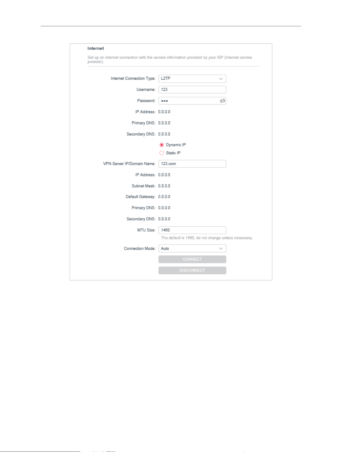
Chapter 4
• Username/Password - Enter the username and password provided by your ISP. These
fields are case-sensitive.
• VPN Server IP/ Domain Name - Enter the VPN server’s IP address or domain name
provided by your ISP.
• MTU Size - The default MTU size is “1460” bytes, which is usually fine. It is not
recommended that you change the default MTU Size unless required by your ISP.
• Connection Mode
• Auto - In this mode, the internet connection reconnects automatically any it gets
disconnected.
• On Demand - In this mode, the internet connection will be terminated automatically
after a specified inactivity period (Max Idle Time) and be re-established when you
attempt to access the internet again.
19
Chapter 4
• Manual - In this mode, the internet connection is controlled manually by clicking the
Connect/Disconnect button. This mode also supports the Max Idle Time function
as On Demand mode. Enter a maximum time (in minutes), the internet connection
can be inactive before it is terminated into the Max Idle Time. The default value is
15 minutes. If you want the internet connection remains active all the time, enter 0
(zero).
Note:
Sometimes the connection cannot be terminated although you have specified the Max Idle Time because some applications
are visiting the internet continually in the background.
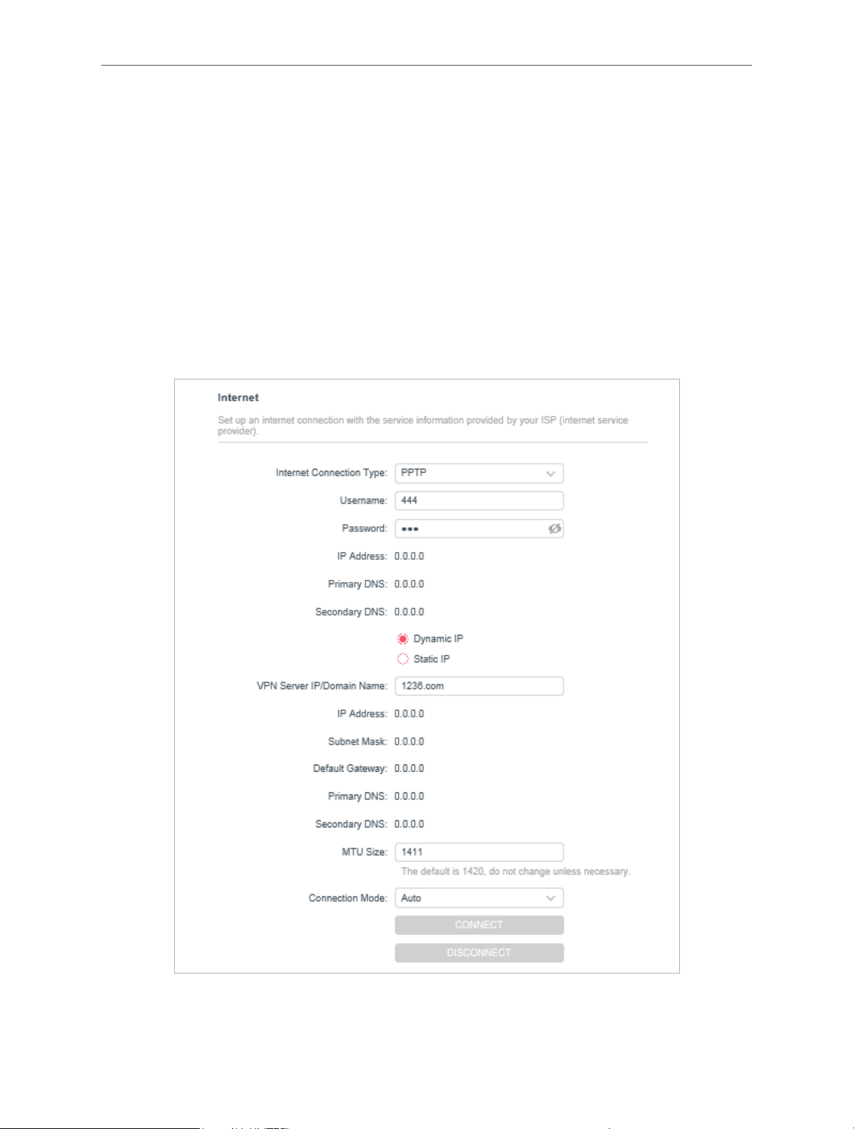
PPTP
If your ISP provides PPTP connection, please select PPTP.
• Username/Password - Enter the username and password provided by your ISP. These
fields are case-sensitive.
20
Chapter 4
• VPN Server IP/ Domain Name - Enter the VPN server’s IP address or domain name
provided by your ISP.
• MTU Size - The default MTU size is “1420” bytes, which is usually fine. It is not
recommended that you change the default MTU Size unless required by your ISP.
• Connection Mode
• Auto - In this mode, the internet connection reconnects automatically any it gets
disconnected.
• On Demand - In this mode, the internet connection will be terminated automatically
after a specified inactivity period (Max Idle Time) and be re-established when you
attempt to access the internet again.
• Manual - In this mode, the internet connection is controlled manually by clicking the
Connect/Disconnect button. This mode also supports the Max Idle Time function
as On Demand mode. Enter a maximum time (in minutes), the internet connection
can be inactive before it is terminated into the Max Idle Time. The default value is
15 minutes. If you want the internet connection remains active all the time, enter 0
(zero).
Note:
Sometimes the connection cannot be terminated although you have specified the Max Idle Time because some applications
are visiting the internet continually in the background.
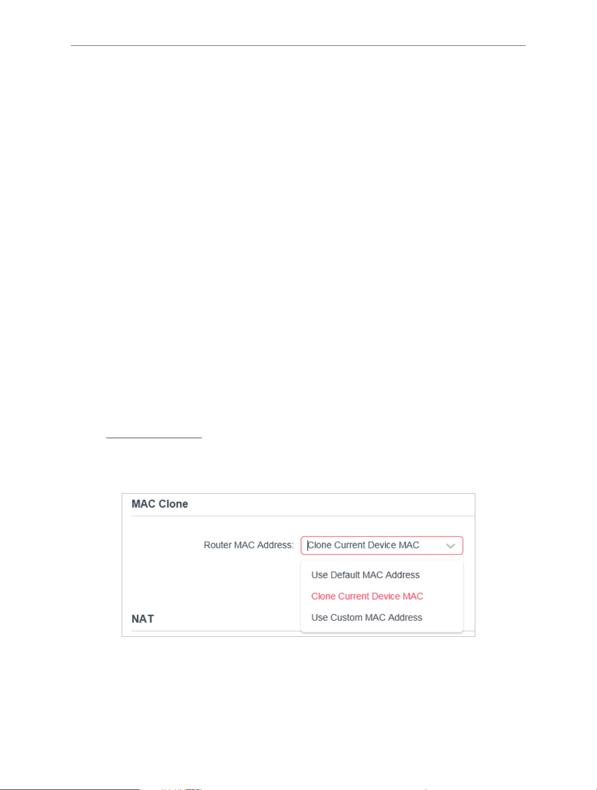
4. 2. 3. MAC Clone
1. Visit http://mwlogin.net, and log in with the password you set for the router.
2. Go to Advanced > Network > Internet and locate the MAC Clone section.
3. Configure Router MAC Address and click SAVE.
• Use Default MAC Address - Do not change the default MAC address of your router
in case the ISP does not bind the assigned IP address to the MAC address.
• Use Current MAC Address - Select to copy the current MAC address of the
computer that is connected to the router, in case the ISP binds the assigned IP
address to the MAC address.
21

Chapter 4
• Use Custom MAC Address - Select if your ISP requires you to register the MAC
address and enter the correct MAC address in this field, in case the ISP binds the
assigned IP address to the specific MAC address.
Note:
• You can only use the MAC Address Clone function for PCs on the LAN.
• If you have changed the WAN MAC address when the WAN connection is PPPoE, it will not take effect until the connection is
re-established.
4. 2. 4. LAN
1. Visit http://mwlogin.net, and log in with the password you set for the router.
2. Go to Advanced > Network > LAN.
3. Configure the IP parameters of the LAN and click SAVE.
• MAC Address - The physical address of the LAN ports. The value can not be changed.
• IP Address - Enter the IP address in dotted-decimal notation of your router (the default
one is 192.168.1.1).
• Subnet Mask - An address code that determines the size of the network. Normally
255.255.255.0 is used as the subnet mask.
Note:
• If you have changed the IP address, you must use the new IP address to log in.
• If the new IP address you set is not in the same subnet as the old one, the IP address pool in the DHCP Server will be
configured automatically, but the Virtual Server and DMZ Host will not take effect until they are re-configured.
4. 2. 5. IPTV/VLAN
1. Visit http://mwlogin.net, and log in with the password you set for the router.
2. Go to Advanced > Network > IPTV/VLAN.
3. Configure IPTV/VLAN settings if you want to enjoy IPTV or VoIP service, or if your ISP
requires VLAN tags.
22

Chapter 4
• IPTV/VLAN - Select to enable the IPTV feature.
• Mode - Select the appropriate mode according to your ISP.
• LAN 1/2 - Assign your LAN port to whether function as the internet supplier or as the IPTV
supplier.
4. 2. 6. DHCP Server
By default, the DHCP (Dynamic Host Configuration Protocol) Server is enabled and the
router acts as a DHCP server; it dynamically assigns TCP/IP parameters to client devices
from the IP Address Pool. You can change the settings of DHCP Server if necessary, and
you can reserve LAN IP addresses for specified client devices.
• To specify the IP address that the router assigns:
1. Visit http://mwlogin.net, and log in with the password you set for the router.
2. Go to Advanced > Network > DHCP Server and locate the DHCP Server section.
1. Tick the Enable checkbox.
2. Enter the starting and ending IP addresses in the IP Address Pool.
3. Enter other parameters if the ISP offers. The Default Gateway is automatically filled in
and is the same as the LAN IP address of the router.
23

Chapter 4
4. Click SAVE.
Note:
To use the DHCP server function of the router, you must configure all computers on the LAN as Obtain an IP Address
automatically.
• To reserve an IP address for a specified client device:
1. Visit http://mwlogin.net, and log in with the password you set for the router.
2. Go to Advanced > Network > DHCP Server and locate the Address Reservation
section.
3. Click Add in the Address Reservation section.
4. Click VIEW CONNECTED DEVICES and select the you device you want to reserve an IP
for. Then the MAC and IP Address will be automatically filled in. You can also enter the
MAC and IP address of the client device.
• To check the DHCP client list:
1. Visit http://mwlogin.net, and log in with the password you set for the router.
2. Go to Advanced > Network > DHCP Server and locate the DHCP Client List section. You
can see the device information of the list.
3. Click Refresh to see the current attached devices.
24

Chapter 4
4. 2. 7. Dynamic DNS
The router offers the DDNS (Dynamic Domain Name System) feature, which allows the
hosting of a website, FTP server, or e-mail server with a fixed domain name (named by
yourself) and a dynamic IP address. Thus your friends can connect to your server by
entering your domain name no matter what your IP address is. Before using this feature, you
need to sign up for DDNS service providers such as www.comexe.cn, www.dyndns.org, or
www.noip.com. The Dynamic DNS client service provider will give you a password or key.
1. Visit http://mwlogin.net, and log in with the username and password you set for the
router.
2. Go to Advanced > Network > Dynamic DNS.
3. Select the DDNS Service Provider: NO-IP or DynDNS. If you don’t have a DDNS account,
you have to register first by clicking Register Now.
4. Enter the Username for your DDNS account.
5. Enter the Password for your DDNS account.
6. Enter the Domain Name you received from dynamic DNS service provider here.
7. If your service provider is NO-IP, select WAN IP binding to ensure that the domain name
is bound to the WAN IP of this router.
25

Chapter 4
8. Click LOGIN AND SAVE.
4. 2. 8. Static Routing
Static Routing is a form of routing that is configured manually by a network administrator or
a user by adding entries into a routing table. The manually-configured routing information
guides the router in forwarding data packets to the specific destination.
I want to:
Visit multiple networks and servers at the same time.
For example, in a small office, my PC can surf the internet through Router A, but I also want
to visit my company’s network. Now I have a switch and Router B. I connect the devices
as shown in the following figure so that the physical connection between my PC and my
company’s server is established. To surf the internet and visit my company’s network at the
same time, I need to configure the static routing.
Router A
LAN: 192.168.1.1
LAN WAN
POWER
RESET
Switch
192.168.1.100
Router B
LAN WAN
POWER
RESET
LAN: 192.168.1.2
PC
Company’s server
WAN: 172.30.30.100
172.30.30.1
How can I do that?
1. Change the routers’ LAN IP addresses to two different IP addresses on the same subnet.
Disable Router B’s DHCP function.
2. Visit http://mwlogin.net, and log in with the password you set for Router A.
3. Go to Advanced > Network > Routing and locate the Static Routing section.
4. Click Add and finish the settings according to the following explanations:
26

Chapter 4
• Network Destination - The destination IP address that you want to assign to a
static route. This IP address cannot be on the same subnet with the WAN IP or
LAN IP of Router A. In the example, the IP address of the company network is the
destination IP address, so here enter 172.30.30.1.
• Subnet Mask - The Subnet Mask determines which portion of an IP address is the
network portion, and which portion is the host portion.
• Default Gateway - The IP address of the gateway device to which the data packets
will be sent. This IP address must be on the same subnet with the router’s IP which
sends out data. In the example, the data packets will be sent to the LAN port of
Router B and then to the Server, so the default gateway should be 192.168.1.2.
• Interface - Determined by the port (WAN/LAN) that sends out data packets. In the
example, the data are sent to the gateway through the LAN port of Router A, so LAN
should be selected.
• Description - Enter a description for this static routing entry.
5. Click SAVE.
6. Check the Routing Table below. If you can find the entry you’ve set, the static routing is
set successfully.
4. 3. Wireless
4. 3. 1. Wireless Settings
1. Visit http://mwlogin.net, and log in with the password you set for the router.
2. Go to Advanced > Wireless > Wireless Settings.
3. Configure the wireless settings for the wireless network and click SAVE.
27

Chapter 4
• 2.4GHz - Select this checkbox to enable the 2.4GHz wireless network.
• Network Name (SSID) - Enter a value of up to 32 characters. The same Name (SSID) must
be assigned to all wireless devices in your network.
• Hide SSID - Select this checkbox if you want to hide the 2.4GHz network name (SSID)
from the Wi-Fi network list. In this case, you need to manually join the network.
• Security - Select an option from the Security drop-down list.
• None - No security. It is highly recommend you enable the wireless security to
protect your wireless network from unauthorized access.
• WPA-PSK/WPA2-Personal - It’s the WPA/WPA2 authentication type based on pre-
shared passphrase. It’s also the recommended security type.
• WPA /WPA2-Enterprise - It’s based on Radius Server.
• WEP - It is based on the IEEE 802.11 standard.
• Version - Keep default version value.
• Encryption - Select Auto, TKIP or AES. We recommend you keep the default settings.
• Transmit Power - Select High, Middle or Low to specify the data transmit power. The
default and recommended setting is High.
• Channel Width - Select a channel width (bandwidth) for the wireless network.
• Channel - Select an operating channel for the wireless network. It is recommended to
leave the channel to Auto, if you are not experiencing the intermittent wireless connection
issue.
• Mode - You can choose the appropriate “Mixed” mode.
4. 3. 2. Guest Network
Guest Network allows you to provide Wi-Fi access for guests without disclosing your host
network. When you have guests in your house, apartment, or workplace, you can create a
28

Chapter 4
guest network for them. In addition, you can customize guest network settings to ensure
network security and privacy.
• Create a Guest Network
1. Visit http://mwlogin.net, and log in with the password you set for the router.
2. Go to Wireless or Advanced > Wireless > Guest Network.
3. Enable the Guest Network function.
4. Create a network name for your guest network.
5. Select the Security type and create the Password of the guest network.
6. Click SAVE. Now you guests can access your guest network using the SSID and
password you set!
• Customize Guest Network Options
1. Visit http://mwlogin.net, and log in with the password you set for the router.
2. Go to Advanced > Wireless > Guest Network. Locate the Guest Permissions section.
3. Customize guest network options according to your needs.
• Allow guests to see each other
Tick this checkbox if you want to allow the wireless clients on your guest network to
communicate with each other via methods such as network neighbors and Ping.
• Allow guests to access my local network
Tick this checkbox if you want to allow the wireless clients on your guest network to
communicate with the devices connected to your router’s LAN ports or main network
via methods such as network neighbors and Ping.
4. Click SAVE. Now you can ensure network security and privacy!
29

Chapter 4
4. 3. 3. Wireless Schedule
The wireless function can be automatically off at a specific time when you do not need the
wireless function.
1. Visit http://mwlogin.net, and log in with the password you set for the router.
2. Go to Advanced > Wireless > Wireless Schedule.
3. Enable the Wireless Schedule function.
4. Click Add to specify a wireless off period during which you need the wireless off
automatically, and click SAVE.
Note:
• The effective wireless schedule is based on the time of the router. You can go to Advanced > System > Time to modify the
time.
• The wireless network will be automatically turned on after the time period you set.
30

Chapter 4
4. 3. 4. WPS
WPS (Wi-Fi Protected Setup) can help you to quickly and securely connect to a network.
This section will guide you to add a new wireless device to your router’s network quickly via
WPS.
Note:
The WPS function cannot be configured if the wireless function of the router is disabled. Please make sure the wireless
function is enabled before configuration.
1. Visit http://mwlogin.net, and log in with the password you set for the router.
2. Go to Advanced > Wireless > WPS.
3. Follow one of the following two methods to connect your client device to the router’s Wi-
Fi network.
Method ONE: Using a PIN
• Connects via the Client’s PIN
1. Keep the WPS Status as Enabled and select Client’s PIN.
2. Enter the PIN of your device and click CONNECT. Then your device will get connected to
the router.
• Connects via the Router’s PIN
1. Keep the WPS Status as Enabled and select Router’s PIN.
31

Chapter 4
2. Enter the router’s PIN on your personal device. You can also generate a new one.
Note:
PIN (Personal Identification Number) is an eight-character identification number preset to each router. WPS supported devices
can connect to your router with the PIN.
Method TWO: Push the WPS Button
Click Start on the screen. Within two minutes, press the WPS button on your device. A
Device-( XX-X X-XX-X X-XX-X X) Connected message should appear on the screen and the
LED should change from blinking to solid on, indicating successful WPS connection.
Note:
XX-XX-XX-XX-XX-XX is the MAC address of your device.
4. 3. 5. Additional Settings
1. Visit http://mwlogin.net, and log in with the password you set for the router.
2. Go to Advanced > Wireless > Additional Settings.
3. Configure the advanced settings of your wireless network and click Save.
Note:
If you are not familiar with the setting items on this page, it’s strongly recommended to keep the provided default values;
otherwise it may result in lower wireless network performance.
32

Chapter 4
• Enable WMM - WMM function can guarantee the packets with high-priority messages
being transmitted preferentially.
• Enable Short GI - It is recommended to enable this function, for it will increase the data
capacity by reducing the guard interval time.
• AP Isolation - This function isolates all connected wireless stations so that wireless
stations cannot access each other through WLAN.
• Beacon Interval - Enter a value between 40-1000 milliseconds for Beacon Interval here.
Beacon Interval value determines the time interval of the beacons. The beacons are the
packets sent by the router to synchronize a wireless network. The default value is 100.
• RTS Threshold - Here you can specify the RTS (Request to Send) Threshold. If the packet
is larger than the specified RTS Threshold size, the router will send RTS frames to a
particular receiving station and negotiate the sending of a data frame. The default value is
2346.
• DTIM Interval - This value determines the interval of the Delivery Traffic Indication
Message (DTIM). A DTIM field is a countdown field informing clients of the next window for
listening to broadcast and multicast messages. When the router has buffered broadcast
or multicast messages for associated clients, it sends the next DTIM with a DTIM Interval
value. You can specify the value between 1-255 Beacon Intervals. The default value is 1,
which indicates the DTIM Interval is the same as Beacon Interval.
• Group Key Update Period - Enter a number of seconds (minimum 30) to control the time
interval for the encryption key automatic renewal. The default value is 0, meaning no key
renewal.
33

Chapter 4
4. 4. NAT Forwarding
The router’s NAT (Network Address Translation) feature makes the devices on the LAN
use the same public IP address to communicate on the internet, which protects the local
network by hiding IP addresses of the devices. However, it also brings about the problem
that external hosts cannot initiatively communicate with the specified devices in the local
network.
With the forwarding feature, the router can traverse the isolation of NAT so that clients on
the internet can reach devices on the LAN and realize some specific functions.
The Mercusys router includes four forwarding rules. If two or more rules are set, the priority
of implementation from high to low is Port Forwarding, Port Triggering, UPNP and DMZ.
4. 4. 1. Port Forwarding
When you build up a server in the local network and want to share it on the internet, Port
Forwarding can realize the service and provide it to internet users. At the same time Port
Forwarding can keep the local network safe as other services are still invisible from the
internet.
Port Forwarding can be used to set up public services in your local network, such as HTTP,
FTP, DNS, POP3/SMTP and Telnet. Different service uses different service port. Port 80 is
used in HTTP service, port 21 in FTP service, port 25 in SMTP service and port 110 in POP3
service. Please verify the service port number before the configuration.
I want to:
Share my personal website I’ve built in local network with my friends through the internet.
For example, the personal website has been built in my home PC (192.168.1.100). I hope
that my friends on the internet can visit my website in some way. My PC is connected to the
router with the WAN IP address 218.18.232.154.
Personal Website
Home
LAN
Router
LAN WAN
POWER
RESET
WAN: 218.18.232.154
1. Set your PC to a static IP address, for example 192.168.1.100.
2. Visit http://mwlogin.net, and log in with the password you set for the router.
3. Go to Advanced > NAT Forwarding > Port Forwarding.
34

4. Click Add.
Chapter 4
5. Click VIEW COMMON SERVICES and select HTTP. The External Port, Internal Port and
Protocol will be automatically filled in.
6. Click VIEW CONNECTED DEVICES and select your home PC. The Device IP
Address will be automatically filled in. Or enter the PC’s IP address 192.168.1.100
manually in the Device IP Address field.
7. Click SAVE.
Note:
• It is recommended to keep the default settings of Internal Port and Protocol if you are not clear about which
port and protocol to use.
• If the service you want to use is not in the Common Services list, you can enter the corresponding
parameters manually. You should verify the port number that the service needs.
• You can add multiple virtual server rules if you want to provide several services in a router. Please note that
the External Port should not be overlapped.
Done!
Users on the internet can enter http:// WAN IP (in this example: http:// 218.18.232.154) to
visit your personal website.
Note:
• If you have changed the default External Port, you should use http:// WAN IP: External Port to visit the
website.
• The WAN IP should be a public IP address. For the WAN IP is assigned dynamically by the ISP, it is
recommended to apply and register a domain name for the WAN referring to Dynamic DNS. Then users on
the internet can use http:// domain name to visit the website.
35

Chapter 4
4. 4. 2. Port Triggering
Port triggering can specify a triggering port and its corresponding external ports. When a
host in the local network initiates a connection to the triggering port, all the external ports
will be opened for subsequent connections. The router can record the IP address of the
host. When the data from the internet return to the external ports, the router can forward
them to the corresponding host. Port triggering is mainly applied to online games, VoIPs,
video players and common applications including MSN Gaming Zone, Dialpad, Quick Time 4
players and more.
Follow the steps below to configure the port triggering rules:
1. Visit http://mwlogin.net, and log in with the password you set for the router.
2. Go to Advanced > NAT Forwarding > Port Triggering.
3. Click Add.
4. Click VIEW COMMON SERVICES, and select the desired application. The Triggering Port,
Triggering Protocol and External Port will be automatically filled in. The following picture
takes application MSN Gaming Zone as an example.
5. Click SAVE.
Note:
• You can add multiple port triggering rules as needed.
• The triggering ports can not be overlapped.
• If the application you need is not listed in the Common Services list, please enter the parameters manually. You should verify
the external ports the application uses first and enter them in External Ports field. You can input at most 5 groups of ports
(or port sections). Every group of ports must be set apart with “,”. For example, 2000-2038, 2050-2051, 2085, 3010-3030.
36

Chapter 4
4. 4. 3. UPnP
The UPnP (Universal Plug and Play) protocol allows the applications or host devices
to automatically find the front-end NAT device and send request to it to open the
corresponding ports. With UPnP enabled, the applications or host devices on the local
network and the internet can freely communicate with each other realizing the seamless
connection of the network. You may need to enable the UPnP if you want to use applications
for multiplayer gaming, peer-to-peer connections, real-time communication (such as VoIP
or telephone conference) or remote assistance, etc.
Tips:
• UPnP is enabled by default in this router.
• Only the application supporting UPnP protocol can use this feature.
• UPnP feature needs the support of operating system (e.g. Windows Vista/ Windows 7/ Windows 8, etc. Some of operating
system need to install the UPnP components).
For example, when you connect your Xbox to the router which is connected to the internet
to play online games, UPnP will send request to the router to open the corresponding ports
allowing the following data penetrating the NAT to transmit. Therefore, you can play Xbox
online games without a hitch.
LAN
LAN WAN
WAN
POWER
RESET
RouterXbox
If necessary, you can follow the steps to change the status of UPnP.
1. Visit http://mwlogin.net, and log in with the password you set for the router.
2. Go to Advanced > NAT Forwarding > UPnP and toggle on or off according to your needs.
37

Chapter 4
4. 4. 4. DMZ
When a PC is set to be a DMZ (Demilitarized Zone) host in the local network, it is totally
exposed to the internet, which can realize the unlimited bidirectional communication
between internal hosts and external hosts. The DMZ host becomes a virtual server with
all ports opened. When you are not clear about which ports to open in some special
applications, such as IP camera and database software, you can set the PC to be a DMZ
host.
Note:
DMZ is more applicable in the situation that users are not clear about which ports to open. When it is enabled, the DMZ host is
totally exposed to the internet, which may bring some potential safety hazards. If DMZ is not in use, please disable it in time.
I want to:
Make the home PC join the internet online game without port restriction.
For example, due to some port restriction, when playing the online games, you can log in
normally but cannot join a team with other players. To solve this problem, set your PC as a
DMZ host with all ports opened.
How can I do that?
1. Assign a static IP address to your PC, for example 192.168.1.100.
2. Visit http://mwlogin.net, and log in with the password you set for the router.
3. Go to Advanced > NAT Forwarding > DMZ and select Enable DMZ.
4. Click VIEW CONNECTED DEVICES and select your PC. The DMZ Host IP
Address will be automatically filled in. Or enter the PC’s IP address 192.168.1.100
manually in the DMZ Host IP Address field.
38

Chapter 4
5. Click SAVE.
Done!
You’ve set your PC to a DMZ host and now you can make a team to game with other players.
4. 5. Parental Controls
Parental Controls allows you to set up unique restrictions on internet access for each
member of your family. You can block inappropriate content, set daily limits for the total time
spent online and restrict internet access to certain times of the day.
I want to:
Block access to inappropriate online content for my child’s devices, restrict internet
access to 2 hours every day and block internet access during bed time (10 PM to 7 AM) on
weekdays.
How can I do that?
1. Visit http://mwlogin.net, and log in with the password you set for the router.
2. Go to Advanced > Parental Controls.
3. Click Add to create a profile for a family member.
4. Add basic profile information.
39

1 ) Enter a Name for the profile to make it easier to identify.
Chapter 4
2 ) Under Devices, click
.
3 ) Select the devices that belong to this family member. Access restrictions will be
applied to these devices. Click ADD when finished.
Note: Only devices that have previously been connected to your router’s network are listed here. If you are
unable to find the device you want to add, connect it to your network and then try again.
4 ) Click NEXT.
5. Block content for this profile.
1 ) Enter the key word of the website that you want to block. Click if want to block
multiple websites.
2 ) Click NEXT.
6. Set time restrictions on internet access.
40

Chapter 4
1 ) Enable Time Limits on Monday to Friday and Saturday & Sunday then set the
allowed online time to 2 hours each day.
2 ) Enable Bed Time on School Nights (Sun to Thur) and use the up/down arrows or
enter times in the fields. Devices under this profile will be unable to access the
internet during this time period.
3 ) Click SAVE.
Note: The effective time limits are based on the time of the router. You can go to Advanced > System > Time to modify
the time.
Done!
The amount of time your child spends online is controlled and inappropriate content is
blocked on their devices.
4. 6. QoS
QoS (Quality of Service) is designed to ensure the efficient operation of the network when
come across network overload or congestion. Devices set as high priority will be allocated
more bandwidth and so continue to run smoothly even when there are many devices
connected to the network.
41

Chapter 4
I want to:
Ensure a fast connection of my computer while I play online games for the next 2 hours.
How can I do that
1. Visit http://mwlogin.net, and log in with the password you set for the router.
2. Go to Advanced > QoS.
3. Tick the Enable checkbox of QoS.
4. Enter the maximum upload and download bandwidths provided by your internet service
provider, and then click SAVE. 1Mbps equals to 1,000Kbps.
5. Find your computer in the Device Priority section and toggle on Priority. Select 4 hours
from the drop-down list of Timing. Your computer will be prioritized for the next 4 hours.
Done!
You can now enjoy playing games without lag on your computer for the next 4 hours.
4. 7. Security
This function allows you to protect your home network from cyber attacks and unauthorized
users by implementing these network security functions.
4. 7. 1. Firewall
The SPI (Stateful Packet Inspection) Firewall protects the router from cyber attacks and
validate the traffic that is passing through the router based on the protocol. This function is
enabled by default.
42

Chapter 4
1. Visit http://mwlogin.net, and log in with the password you set for the router.
2. Go to Advanced > Security > Firewall, and configure the parameters as you need. It’s
recommended to keep the default settings.
4. 7. 2. Access Control
Access Control is used to block or allow specific client devices to access your network (via
wired or wireless) based on a list of blocked devices (Blacklist) or a list of allowed devices
(Whitelist).
I want to:
Block or allow specific client devices to access my network (via wired or wireless).
How can I do that?
1. Visit http://mwlogin.net, and log in with the password you set for the router.
2. Go to Advanced > Security > Access Control.
3. Select the access mode to either block (recommended) or allow the device(s) in the list.
To block specific device(s):
1 ) Select Blacklist and click SAVE.
2 ) Click Add and select devices you want to be blocked. You can see the devices have
been added to the blacklist.
43

To allow specific device(s):
1 ) Select Whitelist and click SAVE.
Chapter 4
2 ) Add devices to the whitelist.
• Add connected devices
Click Select From Device List and select the devices you want to be allowed.
• Add unconnected devices
44

Chapter 4
Click Add Manually and enter the Device Name and MAC Address of the device you
want to be allowed.
Done!
Now you can block or allow specific client devices to access your network (via wired or
wireless) using the Blacklist or Whitelist.
4. 7. 3. IP & MAC Binding
IP & MAC Binding, namely, ARP (Address Resolution Protocol) Binding, is used to bind
network device’s IP address to its MAC address. This will prevent ARP Spoofing and other
ARP attacks by denying network access to a device with matching IP address in the Binding
list, but unrecognized MAC address.
I want to:
Prevent ARP spoofing and ARP attacks.
How can I do that?
1. Visit http://mwlogin.net, and log in with the password you set for the router.
2. Go to Advanced > Security > IP & MAC Binding.
3. Enable IP & MAC Binding and click SAVE.
4. Bind your device(s) according to your need.
To bind the connected device(s):
Locate the ARP List section and enable Bind to bind the IP and MAC addresses of a
specific device.
45

Chapter 4
To add a binding entry:
1 ) Click Add in the Binding List section.
2 ) Click VIEW CONNECTED DEVICES and select the device you want to bind. Or enter
the MAC Address and IP Address that you want to bind.
3 ) Click ADD.
4. 8. IPv6
This function allows you to enable IPv6 function and set up the parameters of the router’s
Wide Area Network (WAN) and Local Area Network (LAN).
4. 8. 1. IPv6 Status
1. Visit http://mwlogin.net, and log in with the password you set for the router.
2. Go to Advanced > IPv6, and you can view the current IPv6 status information of the
router.
3. Enable IPv6 and select the mode: Router or Pass-Through (Bridge).
• If you select Router:
46

Fill in WAN and LAN information as required by different connection types.
• Normal: The default connection type.
1 ) Configure the WAN settings.
Chapter 4
2 ) Configure the LAN settings. Fill in Address Prefix provided by your ISP.
3 ) Click SAVE.
• PPPoE: Select this type if your ISP uses PPPoEv6, and provides a username and
password.
1 ) Configure the WAN settings.
47

Chapter 4
2 ) Configure the LAN settings. Fill in Address Prefix provided by your ISP.
• Tunnel 6to4: Select this type if your ISP uses 6 to 4 deployment fort assigning
address.
1 ) Configure the WAN settings.
48

2 ) Configure the LAN settings.
Chapter 4
• If you select Pass-Through (Bridge):
Click SAVE. No configuration is required.
4. 9. System
4. 9. 1. Firmware Upgrade
Mercusys is dedicated to improving and richening the product features, giving users a
better network experience. We will release the latest firmware at Mercusys official website
www.mercusys.com. You can download the latest firmware file from the Support page of
our website and upgrade the firmware to the latest version.
49

Chapter 4
1. Download the latest firmware file for the router from our website www.mercusys.com.
2. Visit http://mwlogin.net, and log in with the password you set for the router.
3. Go to Advanced > System > Firmware Upgrade.
4. Click BROWSE to locate the downloaded firmware file, and click UPGRADE.
4. 9. 2. Backup & Restore
The configuration settings are stored as a configuration file in the router. You can backup
the configuration file in your computer for future use and restore the router to the previous
settings from the backup file when needed.
1. Visit http://mwlogin.net, and log in with the password you set for the router.
2. Go to Advanced > System > Backup & Restore.
To backup configuration settings:
Click BACK UP to save a copy of the current settings in your local computer. A “.bin“ file of
the current settings will be stored in your computer.
To restore configuration settings:
1. Click BROWSE to locate the backup configuration file stored in your computer, and click
RESTORE.
2. Wait a few minutes for the restoring and rebooting.
50

To reset the router to factory default settings:
1. Click FACTORY RESTORE to reset the router.
Chapter 4
2. Wait a few minutes for the restoring and rebooting.
Note:
• During the resetting process, do not turn off or reset the router.
• We strongly recommend you back up the current configuration settings before resetting the router.
4. 9. 3. Change Password
1. Visit http://mwlogin.net, and log in with the password you set for the router.
2. Go to Advanced > System > Administration, and focus on the Change Password section.
3. Enter the old password, then a new password twice (both case-sensitive). Click SAVE.
4. Use the new password for future logins.
4. 9. 4. Local Management
1. Visit http://mwlogin.net, and log in with the password you set for the router.
2. Go to Advanced > System > Administration, and focus on the Local Management
section.
51

• Allow all LAN connected devices to manage the router:
Select All Devices for Local Managers.
• Allow specific devices to manage the router:
1. Select Specified Devices for Local Managers and click SAVE.
Chapter 4
2. Click Add Device.
3. Click VIEW CONNECTED DEVICES and select the device to manage the router from the
Connected Devices list, or enter the MAC address of the device manually.
4. Specify a Description for this entry.
5. Click SAVE.
4. 9. 5. Remote Management
1. Visit http://mwlogin.net, and log in with the password you set for the router.
52

Chapter 4
2. Go to Advanced > System > Administration, and focus on the Remote Management
section.
• Forbid all devices to manage the router remotely:
Do not tick the Enable checkbox of Remote Management.
• Allow all devices to manage the router remotely:
1. Tick the Enable checkbox of Remote Management.
2. Keep the HTTP port as default setting (recommended) or enter a value between 1024 and
65535.
3. Select All Devices for Remote Managers.
4. Click SAVE.
Devices on the internet can log in to http://Router’s WAN IP address:port number (such as
http://113.116.60.229:1024) to manage the router.
Tips:
• You can find the WAN IP address of the router on Network Map > Internet.
• The router’s WAN IP is usually a dynamic IP. Please refer to Dynamic DNS if you want to log in to the router through a
domain name.
• Allow a specific device to manage the router remotely:
53

Chapter 4
1. Tick the Enable checkbox of Remote Management.
2. Keep the HTTP port as default setting (recommended) or enter a value between 1024 and
65535.
3. Select Specified Device for Remote Managers.
4. In the Only this IP Address field, enter the IP address of the remote device to manage the
router.
5. Click SAVE.
Devices using this WAN IP can manage the router by logging in to http://Router’s WAN
IP:port number (such as http://113.116.60.229:1024).
Tips: The router’s WAN IP is usually a dynamic IP. Please refer to Dynamic DNS if you want to log in to the router through a
domain name.
4. 9. 6. System Log
1. Visit http://mwlogin.net, and log in with the password you set for the router.
2. Go to Advanced > System > System Log, and you can view the logs of the router.
54

Chapter 4
3. Click SAVE TO LOCAL to save the system logs to a local disk.
4. 9. 7. Diagnostics
Diagnostic is used to test the connectivity between the router and the host or other
network devices.
1. Visit http://mwlogin.net, and log in with the password you set for the router.
2. Go to Advanced > System > Diagnostics.
3. Enter the information:
1 ) Choose Ping or Tracert as the diagnostic tool to test the connectivity.
• Ping is used to test the connectivity between the router and the tested host, and
measure the round-trip time.
55

Chapter 4
• Tracert is used to display the route (path) your router has passed to reach the
tested host, and measure transit delays of packets across an Internet Protocol
network.
2 ) Enter the IP Address or Domain Name of the tested host.
3 ) Modify the Ping Count number and the Ping Packet Size. It’s recommended to
keep the default value.
4 ) If you have chosen Tracert, you can modify the Traceroute Max TTL. It’s
recommended to keep the default value.
4. Click START to begin the diagnostics.
The figure below indicates the proper connection between the router and the Yahoo server
(www.Yahoo.com) tested through Ping.
The figure below indicates the proper connection between the router and the Yahoo server
(www.Yahoo.com) tested through Tracert.
4. 9. 8. Time
This function allows you to set the time manually or to configure automatic time
synchronization. The router can automatically update the time from an NTP server via the
internet.
1. Visit http://mwlogin.net, and log in with the password you set for the router.
2. Go to Advanced > System > Time.
• To set System Time:
56

Chapter 4
1. Select the way in which the router gets its time: Get from Internet, Get from Managing
Device, Manually.
2. Select your local Time Zone.
3. Enter the address or domain of the NTP Server 1 or NTP Server 2.
4. Click SAVE.
• To set up Daylight Saving Time:
1. Tick the Enable box of Daylight Saving Time.
2. Select the start time from the drop-down list in the Start fields.
3. Select the end time from the drop-down list in the End fields.
4. Click SAVE.
Note:
This setting will be used for some time-based functions such as firewall. You must specify your time zone once you log in to
the router successfully; otherwise, time-based functions will not take effect.
57

Chapter 4
4. 9. 9. Reboot
Some settings of the router will take effect only after rebooting, and the system will
reboot automatically. You can also reboot the router to clear cache and enhance running
performance.
1. Visit http://mwlogin.net, and log in with the password you set for the router.
2. Go to Advanced > System > Reboot, and you can restart your router.
• To reboot the router manually:
Click REBOOT, and wait a few minutes for the router to reboot.
• To set the router to reboot regularly:
1. Tick the Enable box of Reboot Schedule.
2. Specify the Reboot Time when the router reboots and Repeat to decide how often it
reboots.
3. Click SAVE.
4. 9. 10. LED Control
The LED of the router indicates its activities and status. You can enable the Night Mode
feature to specify a time period during which the LED is off.
1. Visit http://mwlogin.net, and log in with the password you set for the router.
2. Go to Advanced > System > LED Control.
3. Enable Night Mode.
58

Chapter 4
4. Specify the LED off time, and the LED will be off during this period every day.
Note: The effective LED off time is based on the time of the router. You can go to Advanced > System > Time to modify the
time.
5. Click SAVE.
59

Chapter 5
Chapter 5. Congure the Router in
Access Point Mode
This chapter presents how to configure the various features of the router working as an
access point.
It contains the following sections:
• Operation Mode
• Firmware Upgrade
• Backup & Restore
• Administration
• System Log
• Diagnostics
• Time
• Reboot
• LED Control
5. 1. Operation Mode
1. Visit http://mwlogin.net, and log in with the password you set for the router.
2. Go to System > Operation Mode.
3. Select the working mode as needed and click SAVE.
60

Chapter 5
5. 2. Firmware Upgrade
Mercusys is dedicated to improving and richening the product features, giving users a
better network experience. We will release the latest firmware at Mercusys official website
www.mercusys.com. You can download the latest firmware file from the Support page of
our website and upgrade the firmware to the latest version.
1. Download the latest firmware file for the router from our website www.mercusys.com.
2. Visit http://mwlogin.net, and log in with the password you set for the router.
3. Go to System > Firmware Upgrade.
4. Click BROWSE to locate the downloaded firmware file, and click UPGRADE.
61

Chapter 5
5. 2. 1. Backup & Restore
The configuration settings are stored as a configuration file in the router. You can backup
the configuration file in your computer for future use and restore the router to the previous
settings from the backup file when needed.
1. Visit http://mwlogin.net, and log in with the password you set for the router.
2. Go to System > Backup & Restore.
To backup configuration settings:
Click BACK UP to save a copy of the current settings in your local computer. A “.bin“ file of
the current settings will be stored in your computer.
To restore configuration settings:
1. Click BROWSE to locate the backup configuration file stored in your computer, and click
RESTORE.
2. Wait a few minutes for the restoring and rebooting.
62

To reset the router to factory default settings:
1. Click FACTORY RESTORE to reset the router.
2. Wait a few minutes for the restoring and rebooting.
Note:
• During the resetting process, do not turn off or reset the router.
• We strongly recommend you back up the current configuration settings before resetting the router.
5. 3. Administration
Chapter 5
5. 3. 1. Change Password
1. Visit http://mwlogin.net, and log in with the password you set for the router.
2. Go to System > Administration, and focus on the Change Password section.
3. Enter the old password, then a new password twice (both case-sensitive). Click SAVE.
4. Use the new password for future logins.
5. 3. 2. Local Management
1. Visit http://mwlogin.net, and log in with the password you set for the router.
2. Go to System > Administration, and focus on the Local Management section.
• Allow all LAN connected devices to manage the router:
Select All Devices for Local Managers.
63

• Allow specific devices to manage the router:
1. Select Specified Devices for Local Managers and click SAVE.
Chapter 5
2. Click Add Device.
3. Click VIEW CONNECTED DEVICES and select the device to manage the router from the
Connected Devices list, or enter the MAC address of the device manually.
4. Specify a Description for this entry.
5. Click SAVE.
5. 3. 3. System Log
1. Visit http://mwlogin.net, and log in with the password you set for the router.
2. Go to System > System Log, and you can view the logs of the router.
64

Chapter 5
3. Click SAVE TO LOCAL to save the system logs to a local disk.
5. 4. Diagnostics
Diagnostic is used to test the connectivity between the router and the host or other
network devices.
1. Visit http://mwlogin.net, and log in with the password you set for the router.
2. Go to System > Diagnostics.
3. Enter the information:
1 ) Choose Ping or Tracert as the diagnostic tool to test the connectivity.
65

Chapter 5
• Ping is used to test the connectivity between the router and the tested host, and
measure the round-trip time.
• Tracert is used to display the route (path) your router has passed to reach the
tested host, and measure transit delays of packets across an Internet Protocol
network.
2 ) Enter the IP Address or Domain Name of the tested host.
3 ) Modify the Ping Count number and the Ping Packet Size. It’s recommended to
keep the default value.
4 ) If you have chosen Tracert, you can modify the Traceroute Max TTL. It’s
recommended to keep the default value.
4. Click START to begin the diagnostics.
The figure below indicates the proper connection between the router and the Yahoo server
(www.Yahoo.com) tested through Ping.
The figure below indicates the proper connection between the router and the Yahoo server
(www.Yahoo.com) tested through Tracert.
5. 4. 1. Time
This function allows you to set the time manually or to configure automatic time
synchronization. The router can automatically update the time from an NTP server via the
internet.
1. Visit http://mwlogin.net, and log in with the password you set for the router.
66

Chapter 5
2. Go to System > Time.
• To set System Time:
1. Select the way in which the router gets its time: Get from Internet, Get from Managing
Device, Manually.
2. Select your local Time Zone.
3. Enter the address or domain of the NTP Server 1 or NTP Server 2.
4. Click SAVE.
• To set up Daylight Saving Time:
1. Tick the Enable box of Daylight Saving Time.
2. Select the start time from the drop-down list in the Start fields.
3. Select the end time from the drop-down list in the End fields.
4. Click SAVE.
Note:
This setting will be used for some time-based functions such as firewall. You must specify your time zone once you log in to
the router successfully; otherwise, time-based functions will not take effect.
67

Chapter 5
5. 5. Reboot
Some settings of the router will take effect only after rebooting, and the system will
reboot automatically. You can also reboot the router to clear cache and enhance running
performance.
1. Visit http://mwlogin.net, and log in with the password you set for the router.
2. Go to System > Reboot, and you can restart your router.
• To reboot the router manually:
Click REBOOT, and wait a few minutes for the router to reboot.
• To set the router to reboot regularly:
1. Tick the Enable box of Reboot Schedule.
2. Specify the Reboot Time when the router reboots and Repeat to decide how often it
reboots.
3. Click SAVE.
5. 6. LED Control
The LED of the router indicates its activities and status. You can enable the Night Mode
feature to specify a time period during which the LED is off.
1. Visit http://mwlogin.net, and log in with the password you set for the router.
2. Go to System > LED Control.
68

3. Enable Night Mode.
Chapter 5
4. Specify the LED off time, and the LED will be off during this period every day.
Note: The effective LED off time is based on the time of the router. You can go to Advanced > System > Time to modify the
time.
5. Click SAVE.
69

Chapter 6
Chapter 6. Congure the Router in
Range Extender Mode
This chapter presents how to configure the various features of the router working as a range
extender.
It contains the following sections:
• Operation Mode
• Firmware Upgrade
• Backup & Restore
• Administration
• System Log
• Time
• Reboot
• LED Control
6. 1. Operation Mode
1. Visit http://mwlogin.net, and log in with the password you set for the router.
2. Go to System > Operation Mode.
3. Select the working mode as needed and click SAVE.
70

Chapter 6
6. 2. Firmware Upgrade
Mercusys is dedicated to improving and richening the product features, giving users a
better network experience. We will release the latest firmware at Mercusys official website
www.mercusys.com. You can download the latest firmware file from the Support page of
our website and upgrade the firmware to the latest version.
1. Download the latest firmware file for the router from our website www.mercusys.com.
2. Visit http://mwlogin.net, and log in with the password you set for the router.
3. Go to System > Firmware Upgrade.
4. Click BROWSE to locate the downloaded firmware file, and click UPGRADE.
71

Chapter 6
6. 3. Backup & Restore
The configuration settings are stored as a configuration file in the router. You can backup
the configuration file in your computer for future use and restore the router to the previous
settings from the backup file when needed.
1. Visit http://mwlogin.net, and log in with the password you set for the router.
2. Go to System > Backup & Restore.
To backup configuration settings:
Click BACK UP to save a copy of the current settings in your local computer. A “.bin“ file of
the current settings will be stored in your computer.
To restore configuration settings:
1. Click BROWSE to locate the backup configuration file stored in your computer, and click
RESTORE.
2. Wait a few minutes for the restoring and rebooting.
72

To reset the router to factory default settings:
1. Click FACTORY RESTORE to reset the router.
2. Wait a few minutes for the restoring and rebooting.
Note:
• During the resetting process, do not turn off or reset the router.
• We strongly recommend you back up the current configuration settings before resetting the router.
6. 4. Administration
Chapter 6
6. 4. 1. Change Password
1. Visit http://mwlogin.net, and log in with the password you set for the router.
2. Go to System > Administration, and focus on the Change Password section.
3. Enter the old password, then a new password twice (both case-sensitive). Click SAVE.
4. Use the new password for future logins.
6. 4. 2. Local Management
1. Visit http://mwlogin.net, and log in with the password you set for the router.
2. Go to System > Administration, and focus on the Local Management section.
• Allow all LAN connected devices to manage the router:
Select All Devices for Local Managers.
73

• Allow specific devices to manage the router:
1. Select Specified Devices for Local Managers and click SAVE.
Chapter 6
2. Click Add Device.
3. Click VIEW CONNECTED DEVICES and select the device to manage the router from the
Connected Devices list, or enter the MAC address of the device manually.
4. Specify a Description for this entry.
5. Click SAVE.
6. 5. System Log
1. Visit http://mwlogin.net, and log in with the password you set for the router.
2. Go to System > System Log, and you can view the logs of the router.
74

Chapter 6
3. Click SAVE TO LOCAL to save the system logs to a local disk.
6. 5. 1. Time
This function allows you to set the time manually or to configure automatic time
synchronization. The router can automatically update the time from an NTP server via the
internet.
1. Visit http://mwlogin.net, and log in with the password you set for the router.
2. Go to System > Time.
• To set System Time:
75

Chapter 6
1. Select the way in which the router gets its time: Get from Internet, Get from Managing
Device, Manually.
2. Select your local Time Zone.
3. Enter the address or domain of the NTP Server 1 or NTP Server 2.
4. Click SAVE.
• To set up Daylight Saving Time:
1. Tick the Enable box of Daylight Saving Time.
2. Select the start time from the drop-down list in the Start fields.
3. Select the end time from the drop-down list in the End fields.
4. Click SAVE.
Note:
This setting will be used for some time-based functions such as firewall. You must specify your time zone once you log in to
the router successfully; otherwise, time-based functions will not take effect.
6. 6. Reboot
Some settings of the router will take effect only after rebooting, and the system will
reboot automatically. You can also reboot the router to clear cache and enhance running
performance.
1. Visit http://mwlogin.net, and log in with the password you set for the router.
2. Go to System > Reboot, and you can restart your router.
• To reboot the router manually:
Click REBOOT, and wait a few minutes for the router to reboot.
76

Chapter 6
• To set the router to reboot regularly:
1. Tick the Enable box of Reboot Schedule.
2. Specify the Reboot Time when the router reboots and Repeat to decide how often it
reboots.
3. Click SAVE.
6. 7. LED Control
The LED of the router indicates its activities and status. You can enable the Night Mode
feature to specify a time period during which the LED is off.
1. Visit http://mwlogin.net, and log in with the password you set for the router.
2. Go to System > LED Control.
3. Enable Night Mode.
77

Chapter 6
4. Specify the LED off time, and the LED will be off during this period every day.
Note: The effective LED off time is based on the time of the router. You can go to Advanced > System > Time to modify the
time.
5. Click SAVE.
78

Chapter 7
Chapter 7. Congure the Router in
WISP Mode
This chapter presents how to configure the various features of the router working in WISP
mode.
It contains the following sections:
• Operation Mode
• Network
• Wireless
• NAT Forwarding
• Parental Controls
• QoS
• Security
• IPv6
• System
7. 1. Operation Mode
1. Visit http://mwlogin.net, and log in with the password you set for the router.
2. Go to Advanced > Operation Mode.
3. Select the working mode as needed and click SAVE.
79

Chapter 7
7. 2. Network
7. 2. 1. Status
1. Visit http://mwlogin.net, and log in with password you set for the router.
2. Go to Advanced > Network > Status. You can view the current status information of the
router.
80

Chapter 7
• Internet - This field displays the current settings of the internet, and you can configure
them on the Advanced > Network > Internet page.
• Status - Indicates whether the router has been connected to the internet.
• Internet Connection Type - Indicates the way in which your router is connected to
the internet.
• IP Address - The WAN IP address of the router.
• Subnet Mask - The subnet mask associated with the WAN IP address.
81

Chapter 7
• Default Gateway - The Gateway currently used is shown here. When you use
Dynamic IP as the internet connection type, click Renew or Release here to obtain
new IP parameters dynamically from the ISP or release them.
• Primary & Secondary DNS - The IP addresses of DNS (Domain Name System)
server.
• LAN - This field displays the current settings of the LAN, and you can configure them on
the Advanced > Network > LAN page.
• MAC Address - The physical address of the router.
• IP Address - The LAN IP address of the router.
• Subnet Mask - The subnet mask associated with the LAN IP address.
• DHCP Server - This field displays the current settings of DHCP (Dynamic Host
Configuration Protocol) Server, and you can configure them on the Network > DHCP
Server page.
• DHCP Server - Indicates whether the DHCP server is enabled of disabled. It is
enabled by default and the router acts as a DHCP server.
• IP Address Pool - The IP address range for the DHCP server to assign IP addresses.
• Dynamic DNS - This field displays the current settings of the Dynamic DNS (Domain
Name System), and you can configure them on the Advanced > Network > Dynamic DNS
page.
• Service Provider - The Dynamic DNS service provider you have signed up for.
• Host Name - The Domain Name you have entered in the Dynamic DNS page.
• Status - The status of the Dynamic DNS service connection.
7. 2. 2. Internet
1. Visit http://mwlogin.net, and log in with the password you set for the router.
2. Go to Advanced > Network > Internet.
3. Set up the internet connection and click SAVE.
Dynamic IP
If your ISP provides the DHCP service, please select Dynamic IP, and the router will
automatically get IP parameters from your ISP.
Click RENEW to renew the IP parameters from your ISP.
Click RELEASE to release the IP parameters.
82

Chapter 7
• MTU Size - The normal MTU (Maximum Transmission Unit) value for most Ethernet
networks is 1500 Bytes. It is not recommended that you change the default MTU size
unless required by your ISP.
• Host Name - This option specifies the name of the router.
• Get IP with Unicast DHCP - A few ISPs’ DHCP servers do support the broadcast applications. If
you cannot get the IP address normally, you can choose this option (it is rarely required).
Static IP
If your ISP provides a static or fixed IP address, subnet mask, default gateway and DNS
setting, please select Static IP.
83

Chapter 7
• IP Address - Enter the IP address in dotted-decimal notation provided by your ISP.
• Subnet Mask - Enter the subnet mask in dotted-decimal notation provided by your ISP.
Normally 255.255.255.0 is used as the subnet mask.
• Default Gateway - Enter the gateway IP address in dotted-decimal notation provided by
your ISP.
• Primary/Secondary DNS - (Optional) Enter one or two DNS addresses in dotted-decimal
notation provided by your ISP.
• MTU Size - The normal MTU (Maximum Transmission Unit) value for most Ethernet
networks is 1500 bytes. It is not recommended that you change the default MTU size
unless required by your ISP.
PPPoE
If your ISP provides PPPoE connection, select PPPoE.
84

Chapter 7
• Username/Password - Enter the user name and password provided by your ISP. These
fields are case-sensitive.
• Secondary Connection - It’s available only for PPPoE connection. If your ISP provides
an extra connection type, select Dynamic IP or Static IP to activate the secondary
connection.
• MTU Size - The default MTU size is 1480 bytes. It is not recommended that you change
the default MTU size unless required by your ISP.
85

Chapter 7
• Service Name - The service name should not be configured unless you are sure it is
necessary for your ISP. In most cases, leaving these fields blank will work.
• Access Concentrator Name - The access concentrator name should not be configured
unless you are sure it is necessary for your ISP. In most cases, leaving these fields blank
will work.
• Detect Online Interval - The router will detect Access Concentrator online at every
interval. The default value is 10. You can input the value between 0 and 120. The value 0
means no detect.
• IP Address - The default setting is to get an IP address dynamically from your ISP. If your
ISP does not automatically assign IP addresses to the router, please select Use the
Following IP Address and enter the IP address provided by your ISP in dotted-decimal
notation.
• DNS Address - The default setting is to get an IP address dynamically from your ISP. If
your ISP does not automatically assign DNS addresses to the router, please select Use
the Following DNS Addresses and enter the IP address in dotted-decimal notation of
your ISP’s primary DNS server. If a secondary DNS server address is available, enter it as
well.
• Connection Mode - Select an appropriate connection mode that determines how to
connect to the internet.
• Auto - In this mode, the internet connection reconnects automatically any it gets
disconnected.
• On Demand - In this mode, the internet connection will be terminated automatically
after a specified inactivity period (Max Idle Time) and be re-established when you
attempt to access the internet again.
• Time-based - In this mode, the internet connection is only established in a specific
timeframe. If this option is selected, enter the start time and end time. Both are in
HH:MM format.
• Manual - In this mode, the internet connection is controlled manually by clicking the
Connect/Disconnect button. This mode also supports the Max Idle Time function
as On Demand mode. Enter a maximum time (in minutes), the internet connection
can be inactive before it is terminated into the Max Idle Time. The default value is
15 minutes. If you want the internet connection remains active all the time, enter 0
(zero).
Note:
Sometimes the connection cannot be terminated although you have specified the Max Idle Time because some applications
are visiting the internet continually in the background.
L2TP
If your ISP provides L2TP connection, please select L2TP.
86

Chapter 7
• Username/Password - Enter the username and password provided by your ISP. These
fields are case-sensitive.
• VPN Server IP/ Domain Name - Enter the VPN server’s IP address or domain name
provided by your ISP.
• MTU Size - The default MTU size is “1460” bytes, which is usually fine. It is not
recommended that you change the default MTU Size unless required by your ISP.
• Connection Mode
• Auto - In this mode, the internet connection reconnects automatically any it gets
disconnected.
• On Demand - In this mode, the internet connection will be terminated automatically
after a specified inactivity period (Max Idle Time) and be re-established when you
attempt to access the internet again.
87

Chapter 7
• Manual - In this mode, the internet connection is controlled manually by clicking the
Connect/Disconnect button. This mode also supports the Max Idle Time function
as On Demand mode. Enter a maximum time (in minutes), the internet connection
can be inactive before it is terminated into the Max Idle Time. The default value is
15 minutes. If you want the internet connection remains active all the time, enter 0
(zero).
Note:
Sometimes the connection cannot be terminated although you have specified the Max Idle Time because some applications
are visiting the internet continually in the background.
PPTP
If your ISP provides PPTP connection, please select PPTP.
• Username/Password - Enter the username and password provided by your ISP. These
fields are case-sensitive.
88

Chapter 7
• VPN Server IP/ Domain Name - Enter the VPN server’s IP address or domain name
provided by your ISP.
• MTU Size - The default MTU size is “1420” bytes, which is usually fine. It is not
recommended that you change the default MTU Size unless required by your ISP.
• Connection Mode
• Auto - In this mode, the internet connection reconnects automatically any it gets
disconnected.
• On Demand - In this mode, the internet connection will be terminated automatically
after a specified inactivity period (Max Idle Time) and be re-established when you
attempt to access the internet again.
• Manual - In this mode, the internet connection is controlled manually by clicking the
Connect/Disconnect button. This mode also supports the Max Idle Time function
as On Demand mode. Enter a maximum time (in minutes), the internet connection
can be inactive before it is terminated into the Max Idle Time. The default value is
15 minutes. If you want the internet connection remains active all the time, enter 0
(zero).
Note:
Sometimes the connection cannot be terminated although you have specified the Max Idle Time because some applications
are visiting the internet continually in the background.
7. 2. 3. MAC Clone
1. Visit http://mwlogin.net, and log in with the password you set for the router.
2. Go to Advanced > Network > Internet and locate the MAC Clone section.
3. Configure Router MAC Address and click SAVE.
• Use Default MAC Address - Do not change the default MAC address of your router
in case the ISP does not bind the assigned IP address to the MAC address.
• Use Current MAC Address - Select to copy the current MAC address of the
computer that is connected to the router, in case the ISP binds the assigned IP
address to the MAC address.
89

Chapter 7
• Use Custom MAC Address - Select if your ISP requires you to register the MAC
address and enter the correct MAC address in this field, in case the ISP binds the
assigned IP address to the specific MAC address.
Note:
• You can only use the MAC Address Clone function for PCs on the LAN.
• If you have changed the WAN MAC address when the WAN connection is PPPoE, it will not take effect until the connection is
re-established.
7. 2. 4. LAN
1. Visit http://mwlogin.net, and log in with the password you set for the router.
2. Go to Advanced > Network > LAN.
3. Configure the IP parameters of the LAN and click SAVE.
• MAC Address - The physical address of the LAN ports. The value can not be changed.
• IP Address - Enter the IP address in dotted-decimal notation of your router (the default
one is 192.168.1.1).
• Subnet Mask - An address code that determines the size of the network. Normally
255.255.255.0 is used as the subnet mask.
Note:
• If you have changed the IP address, you must use the new IP address to log in.
• If the new IP address you set is not in the same subnet as the old one, the IP address pool in the DHCP Server will be
configured automatically, but the Virtual Server and DMZ Host will not take effect until they are re-configured.
7. 2. 5. DHCP Server
By default, the DHCP (Dynamic Host Configuration Protocol) Server is enabled and the
router acts as a DHCP server; it dynamically assigns TCP/IP parameters to client devices
from the IP Address Pool. You can change the settings of DHCP Server if necessary, and
you can reserve LAN IP addresses for specified client devices.
• To specify the IP address that the router assigns:
1. Visit http://mwlogin.net, and log in with the password you set for the router.
2. Go to Advanced > Network > DHCP Server and locate the DHCP Server section.
90

Chapter 7
1. Tick the Enable checkbox.
2. Enter the starting and ending IP addresses in the IP Address Pool.
3. Enter other parameters if the ISP offers. The Default Gateway is automatically filled in
and is the same as the LAN IP address of the router.
4. Click SAVE.
Note:
To use the DHCP server function of the router, you must configure all computers on the LAN as Obtain an IP Address
automatically.
• To reserve an IP address for a specified client device:
1. Visit http://mwlogin.net, and log in with the password you set for the router.
2. Go to Advanced > Network > DHCP Server and locate the Address Reservation
section.
3. Click Add in the Address Reservation section.
4. Click VIEW CONNECTED DEVICES and select the you device you want to reserve an IP
for. Then the MAC and IP Address will be automatically filled in. You can also enter the
MAC and IP address of the client device.
91
 Loading...