

Page 1
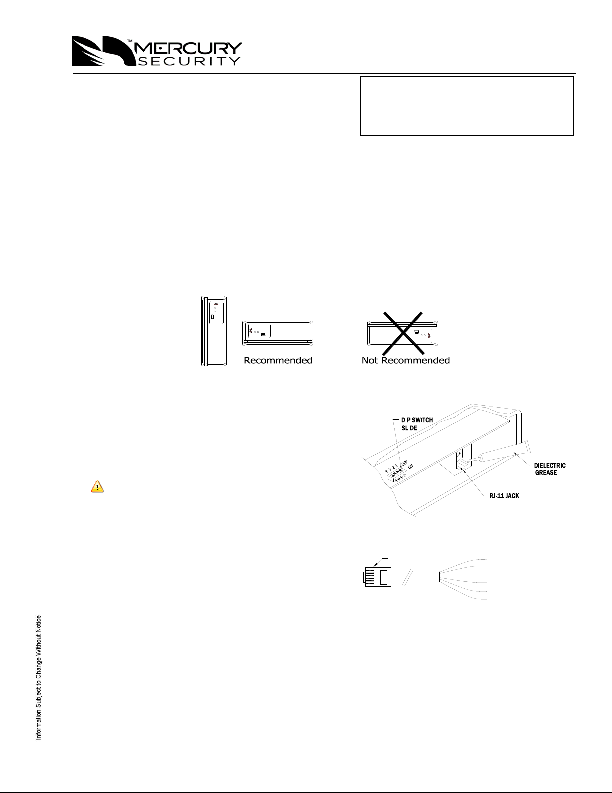
www.mercury-security.com
2355 MIRA MAR AVE. LONG BEACH, CA 90815-1755, (562)986-9105 FAX (562) 986-9205
This device complies with part 15 of the FCC Rules.
Operation is subject to the following two conditions: (1) This
device may not cause harmful interference, and (2) this
device must accept any interference received, including
interference that may cause undesired operation.
MODULAR PLUG
1 (RED) +5 or +12Vdc
2 (GRN) DATA 0/DATA
3 (WHT) DATA 1/CLOCK
4 (BRN) LED
5 (ORG) BUZZER/LED/CP
6 (BLK) GROUND
depends on model
MR5 Magnetic Card Reader
Installation and Specifications
1. General:
The MR5 magnetic stripe card reader is designed for reading standard or high-coercivity magnetic stripe
cards. The reader has a TTL interface with selectable clock/data and data 1/data 0 signaling. A bi-color
LED and a buzzer are standard. The following paragraphs describe instructions for installing and
maintaining the card reader.
2. Mounting the Reader:
Find a suitable location to anchor the reader mounting bracket. The reader may be mounted vertically or
horizontally. See recommended orientation. The mounting of the reader does not require a junction box.
However, rigid conduit is required for outdoor application. A single gang junction box may be used to
provide transition to rigid conduit. If a single gang junction box is used, a wall plate (optional) is available
to cover the junction box. The reader is then secured to the mounting bracket using a UNC6-32 3/8
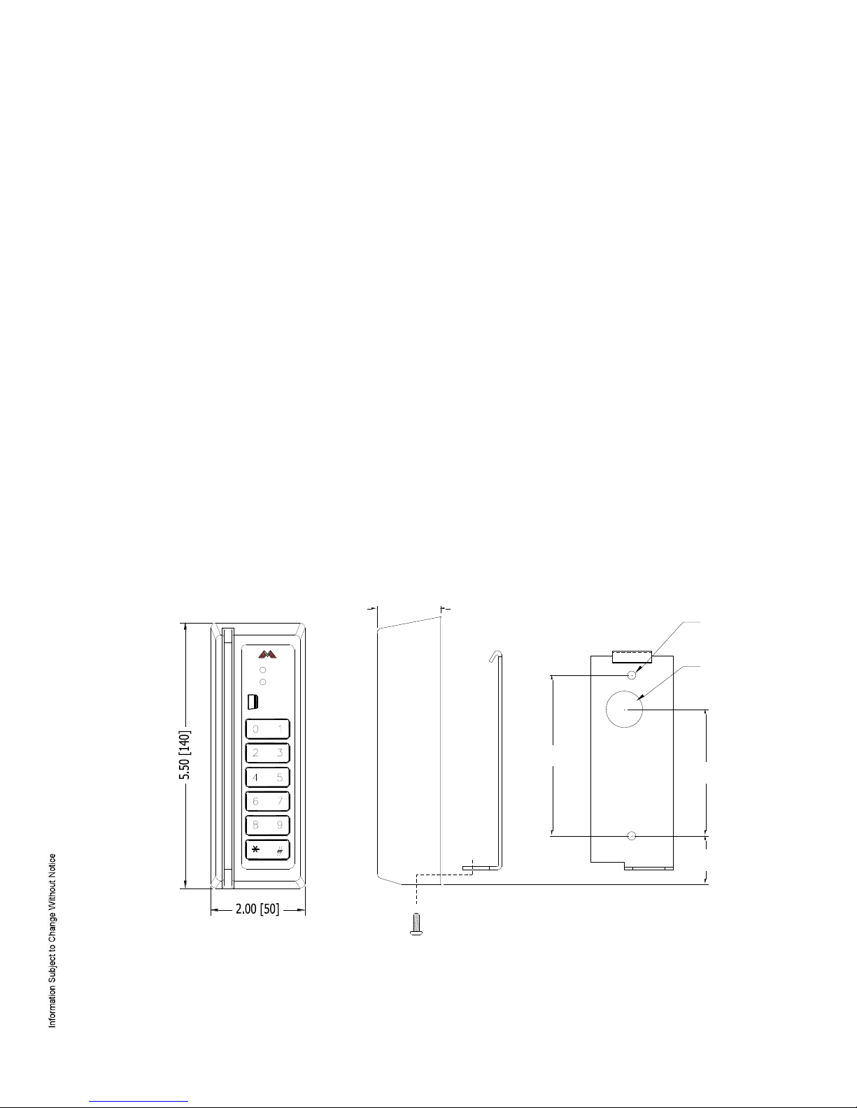
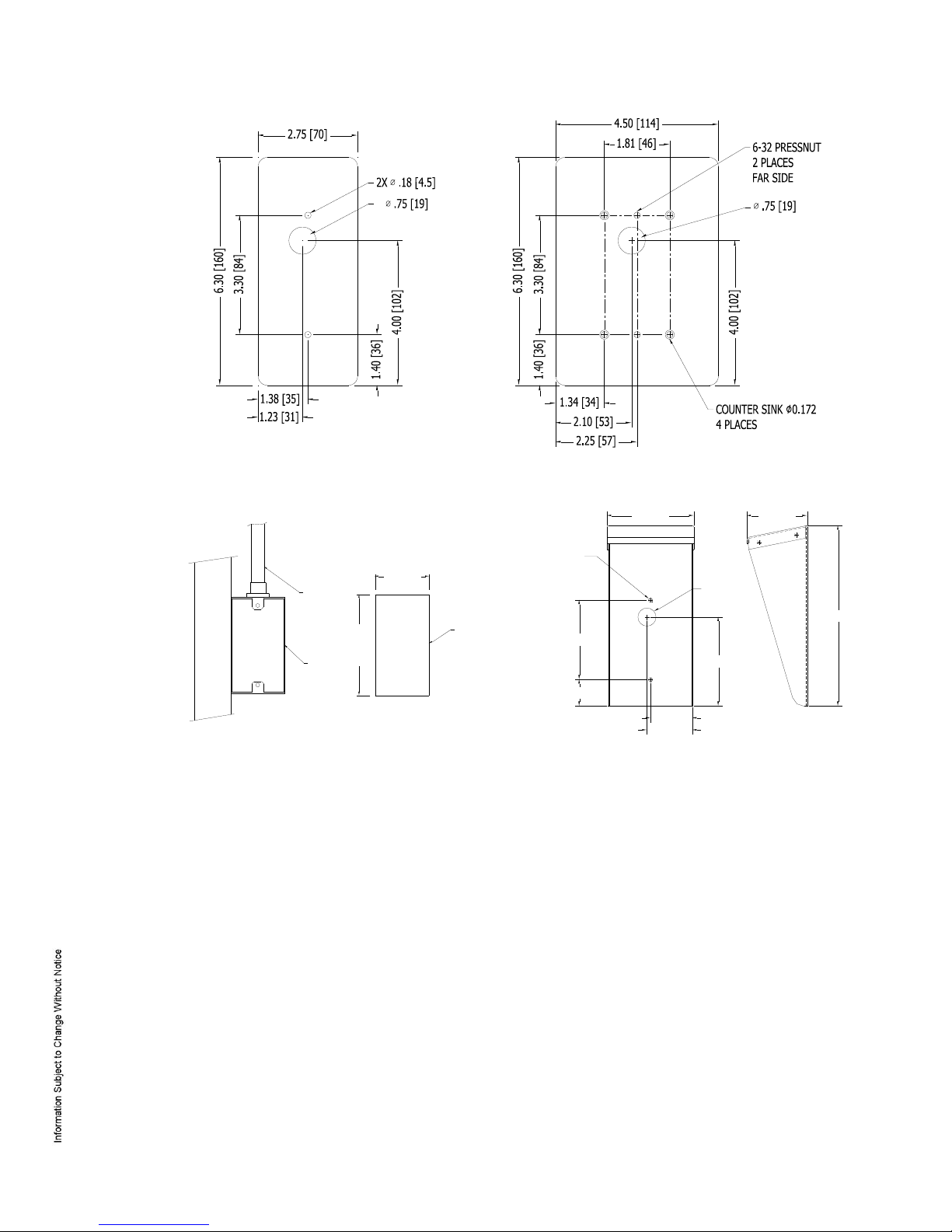
screw. Refer to figures for reader dimensions and typical junction box usage.
3. Weather Proofing the Reader:
MR5 reader is rated for outdoor use over extended
temperature. A tube of dielectric grease is supplied for
the installer to coat field connections to seal out moisture.
After field connection/configuration is made, the grease is
to be applied on the DIP switch slides and the modular
jack to seal out moisture. Squeeze some grease into the
modular jack before connecting the cable.
Do not use sealant to seal reader case to wall.
Doing so will trap water in the reader and may cause
damage to the reader.
4. TTL Interface and Reader Wiring:
The TTL interface has the standard 6-wire interface widely
used in the access control application. The reader has a
RJ-11 modular jack for easy field connection. A short
piece of pre-terminated cable is supplied with each reader
for field wiring. Refer to pin number if the pre-terminated
cable is not used. Cable with wires of 24 AWG or larger
are recommended for field wiring. If a shielded cable is used, connect the cable shield to either earth
ground or signal ground at one end only.
CONFIDENTIAL: For installation and maintenance use only. DO NOT distribute.
Mercury Security © 2015 MR5 DOC 10107-0012 REV 2.00 Page 1
Page 2
SW-4
SW-3
SW-2
SW-1
SELECTION
OFF X X
OFF
Clock/Data (MAG stripe) Output
OFF X X
ON
Data 1/Data 0 (Wiegand) Output
OFF
X
OFF
X
Single Wire LED Control, HI=Red, Low=Green
OFF X ON
X
Two Wire LED Control, No Buzzer Control
OFF
OFF X X
Normal LED Drive
OFF
ON X X
Inverted LED Drive
OFF X X
X
Reserved For Test - set to OFF
5. Grounding the Reader:
To avoid ESD (electro-static discharge) interfering with the operation of the reader, the reader casing
shall be grounded. This can be accomplished by tying the mounting bracket to earth ground locally (e.g.
grounded conduit).
6. Reader Configuration:
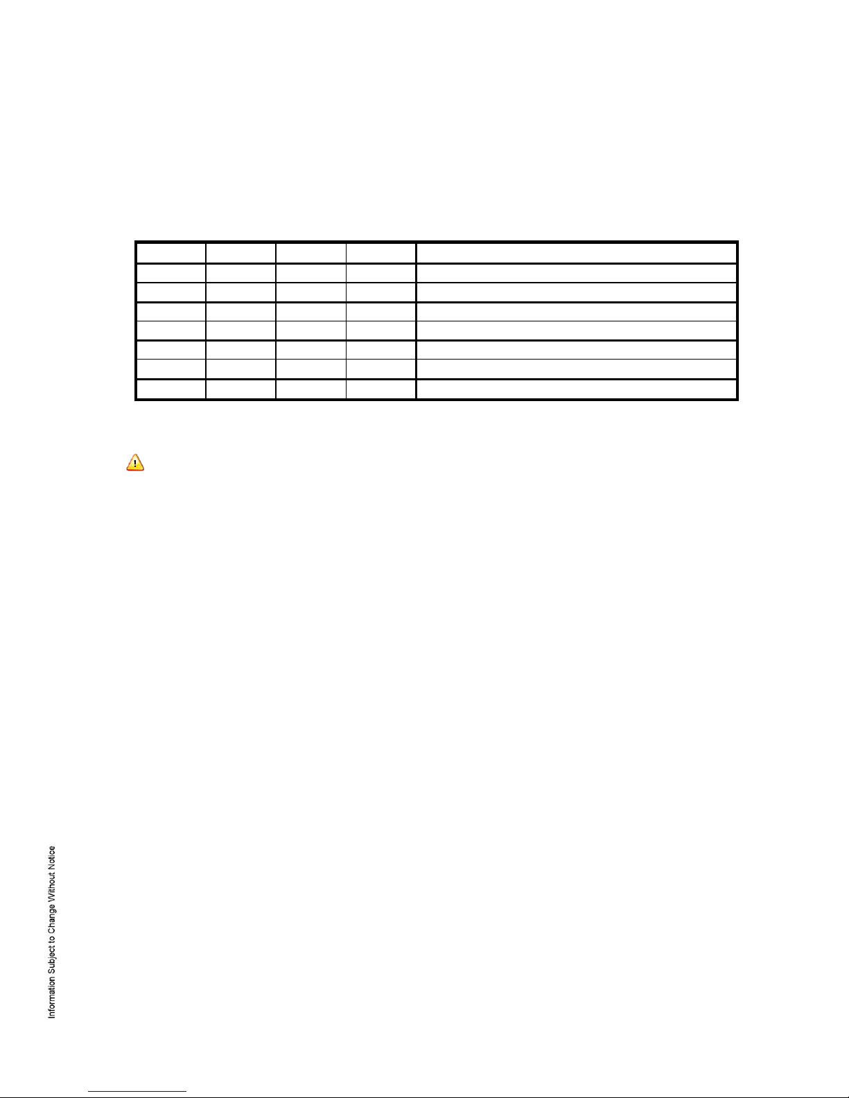
The DIP switches on the MR5 reader are used to configure the reader. See table below:
X = don’t care
7 Reader Verification:
Verify proper connection and correct supply voltage to the reader before applying power!
The reader performs a self-test when power is first applied to the unit. If power-on test is successfully
completed. The reader will turn on the LED for approximately 1 second and sound the buzzer for 1 short
beep. The reader is ready for normal operation.
8. Maintenance:
The readers are designed to provide continuous service with minimal routine maintenance. However,
contaminants (such as magnetic oxides from badges and dirt) tend to accumulate on the read head.
Without regular cleaning, these contaminants will shorten the read head life and increase the probability
of card read error. A maintenance schedule should be developed base on the card reader environment
(dirty or clean) and the usage frequency (light traffic or heavy traffic). Extreme case may require daily
cleaning.
Head cleaning may be done by using a disposable, pre-saturated magnetic head cleaning card. These
cards are readily obtainable from office supply distributors.
The reader exterior surface is covered with high strength polymer and polyester membrane. It may be
cleaned with a soft cloth and mild detergent if required.
9. Specifications:
The reader is for use in low voltage, class 2 circuits only.
Power: Voltage: 5 Volt Model: 5.8 Vdc (4.9 to 6.4 Vdc)
12 Volt Model: 12 Vdc (10.2 to 13.8 Vdc)
Current: 50 mA (20 mA typical)
Data output: data 1/data 0 or clock/data, switch selectable
LED input: 1-wire mode: input not driven: LEDs off
2-wire mode: input < 0.8 Vdc: Red LED on (Inverted, Red LED off)
Mercury Security © 2015 MR5 DOC 10107-0012 REV 2.00 Page 2
input > 3.5 Vdc: Red LED on (Inverted, Green LED on)
input < 0.8 Vdc: Green LED on (Inverted, Red LED on)
Page 3
1.00 [25]
DIMENSION: INCH [mm]
2.60 [66]
3.30 [84]
1.30 [33]
2X Ø.18 [4.5]
MOUNTING HOLE
Ø.75 [19]
Specifications (continued):
Buzzer/LED/CP: 1-wire mode: input not driven or > 3.5 Vdc: buzzer off
input < 0.8 Vdc: buzzer on
2-wire mode: input < 0.8 Vdc: Green LED on (Inverted, Green LED off)
Card Present output<0.8 Vdc while reader is outputting data
optional (CP)
Mechanical: Dimension: 1.95in. (50mm) W x 1.30in. (33mm) H x 5.50in. (140mm) L
Weight: 10 oz. (284 g) nominal
Material: Case: die cast aluminum, gray powder coat standard or
black (optional)
Mounting bracket: 18 gauge stainless steel
Wall plate: 18 gauge CRS, gray powder coat standard or
black (optional)
Weather shield: 18 gauge stainless steel
Card: 75 bpi, ANSI X4.16, Track 2 standard, Speed 3 to 50 ips
Read Head: 1,000,000 passes typical
Distance: 500 feet (152m) with 18 AWG wires.
Environmental: Temperature: -55 to +85 degrees C, storage
-40 to +75 degrees C, operating
Humidity: 0-100 % RHNC, standard
14. Reader Mounting Dimensions:
Mercury Security © 2015 MR5 DOC 10107-0012 REV 2.00 Page 3
Page 4
Optional Single Gang Wall Plate - part# WP-10
Optional Double Gang Wall Plate - part# WP-20
Fitting Rigid Conduit to Junction Box
Optional Weather Shield - part# WS-10
1/2" RIGID
1-GANG
CONDUIT
BOX
WALL STUD
2.25 [57]
4.20 [107]
WALL OPENING
FOR J-BOX
2X Ø .18 [4.5]
3.30 [84]
1.10 [28]
3.60 [91]
3.70 [94]
1.90 [48]
7.50 [190]
1.75 [44]
2.50 [64]
Ø.75 [19]
Warranty
Mercury Security warrants the product is free from defects in material and workmanship under normal use
and service with proper maintenance for two years from the date of factory shipment. Mercury Security
assumes no responsibility for products damaged by improper handling or installation. This warranty is
limited to the repair or replacement of the defective unit.
There are no expressed warranties other than set forth herein. Mercury Security does not make, nor
intends, nor does it authorize any agent or representative to make any other warranties, or implied
warranties, and expressly excludes and disclaims all implied warranties of merchantability or fitness for a
particular purpose.
Returns must be accompanied by a Return Material Authorization (RMA) number obtained from customer
service, and prepaid postage and insurance.
Liability
The Interface should only be used to control exits from areas where an alternative method for exit is
available. This product is not intended for, nor is rated for operation in life-critical control applications.
Mercury Security is not liable under any circumstances for loss or damage caused by or partially caused
by the misapplication or malfunction of the product. Mercury Security’s liability does not extend beyond
the purchase price of the product.
Mercury Security © 2015 MR5 DOC 10107-0012 REV 2.00 Page 4
 Loading...