

Page 1
Systems Monitor
Operation Manual
THIS MANUAL DESCRIBES THE SMARTCRAFT GAUGE
SYSTEMS AVAILABLE FOR YOUR BOAT
2004, Mercury Marine
90-895202 204
Page 2

0
Page 3

TABLE OF CONTENTS
Legend 3. . . . . . . . . . . . . . . . . . . . . . . . . . . . . . . . . . . . . . . . . . . . . .
Basic Operation 4. . . . . . . . . . . . . . . . . . . . . . . . . . . . . . . . . . . . .
Initial Power Up (Or After Master Reset) 4. . . . . . . . . . . . . .
Master Reset 6. . . . . . . . . . . . . . . . . . . . . . . . . . . . . . . . . . . . . . . .
Standard Display Screens 7. . . . . . . . . . . . . . . . . . . . . . . . . . . .
Shallow Water Alarm 11. . . . . . . . . . . . . . . . . . . . . . . . . . . . . .
Warning System 12. . . . . . . . . . . . . . . . . . . . . . . . . . . . . . . . . . . .
Warning Display Screens 12. . . . . . . . . . . . . . . . . . . . . . . . . .
CAL 1 Calibration 14. . . . . . . . . . . . . . . . . . . . . . . . . . . . . . . . . . .
CAL 2 Calibration 20. . . . . . . . . . . . . . . . . . . . . . . . . . . . . . . . . . .
Fuel Tank Calibration 22. . . . . . . . . . . . . . . . . . . . . . . . . . . . . .
NOTE:This manual shows all the Monitor display screens that
are available. Depending on your type of engine, not all these
screens will apply.
1
Page 4

2
Page 5

LEGEND
A =
B =
C =
D =
E =
F =
I =
L =
N =
O =
P =
S =
T=
U=
= Engine
= Fuel
= Water Temperature
= Water Pressure
= Oil
= Alarm
3
Page 6
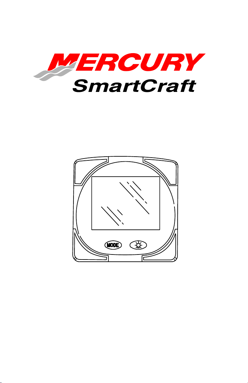
BASIC OPERATION
The Monitor is an LCD multi-function display gauge. A variety of
displays can be activated using the
button.
Pressing the
tachometer (RPM), fuel flow, power trim position, engine temp,
water pressure, battery voltage, range (if calibrated), and water
depth (if equipped with transducer).
The Monitor will power up when the ignition is turned on.
The display includes a backlight which allows you to read it at night.
The backlight brightness is adjustable using
In the event of a warning alarm, the warning icon(s)
displayed.
button scrolls the following displays: fuel used,
button.
will be
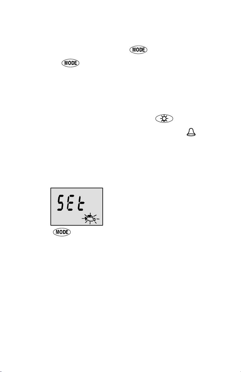
Initial Power Up (Or After Master Reset)
Unit will display software level then flash the word “SEt” in
conjunction with engine icon, indicating it is ready to start the
auto–detect procedure.
Press the button.
AUTO-DETECTION
The unit will begin it’s “Auto-detection” of engine type procedure. In
this procedure the Monitor checks with the engine control module
(ECM) to see what type of engine you have and presets the data
monitoring screens accordingly, (e.g., If Monitor detects an inboard
engine connected to the data network it will turn off all engine/drive
TRIM functions as these functions are not used in an inboard engine
installation). The intention is to make initial setup easier. It also checks
for other Monitors to allow for appropriate engine location and station
location setting. When setting up monitors for multi–engine or
multi–station installations, perform a power up or a master reset on all
monitors before performing the auto–detect function. Once all of the
monitors display ”SEt” then, perform auto–detect on the monitors.
4
Page 7
BASIC OPERATION
Initial Power Up (Or After Master Reset)
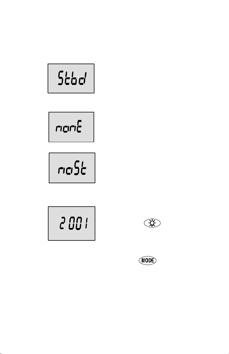
INITIAL AUTO-DETECTION ERROR MESSAGES:
Flashing “Stbd” – More than one of
the engine computers (ECMs) are
configured as a starboard engine.
The engines must be programmed
for proper engine location using a
DDT or Quicksilver Diagnostic Tool.
Flashing “nonE” – The gauge does
not see any engine computers
(ECMs). Please check wiring for bad
connections and for proper amount
of terminator resistors.
Flashing “noSt” – None of the
engine computers (ECMs) are
configured as a starboard engine.
Engines may not be compatible or
must be programmed for proper
engine location by using a DDT or
Quicksilver Diagnostic Tool.
Flashing “2001” – You will need to
manually select your engine type.
Use the button to scroll
through the choices. Stnd = Stern
Drive, Inbd = Inboard, JEtd = Jet
Drive, Out2 = Outboard 2 Stroke,
Out4 = Outboard 4 Stroke.
Press to continue.
5
Page 8
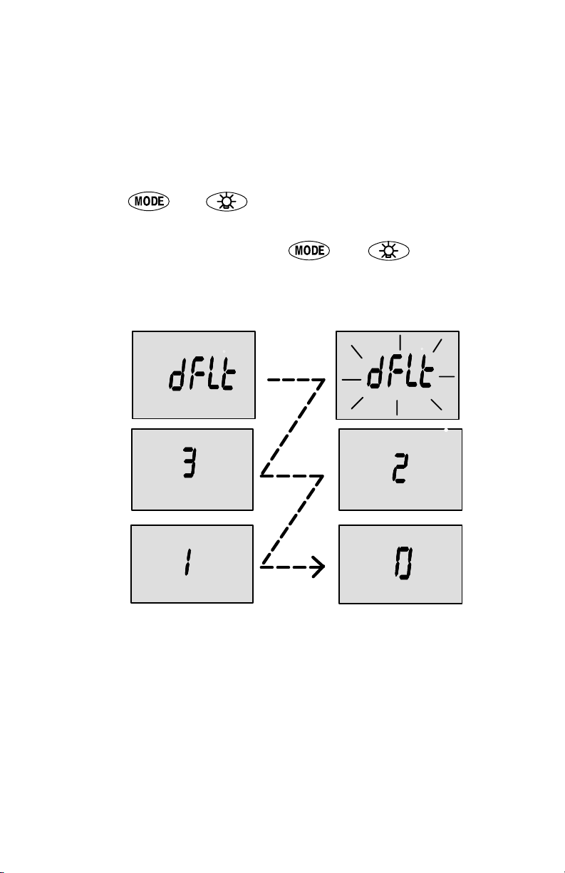
MASTER RESET
You can return the gauge back to factory presets through the Master
Reset command.
IMPORTANT: Performing a master reset will reset the unit back
to all factory defaults, thus eliminating any installation
calibrations performed during set up of product.
1. Hold in
see the word “dFLt”. Let go of the buttons.
2. Immediately press and hold in
unit counts down to zero “0”.
3. The “SEt” message flashing on the screen indicates that the
unit has been reset to factory defaults.
and for approximately 12 seconds. You will
and again until the
6
Page 9
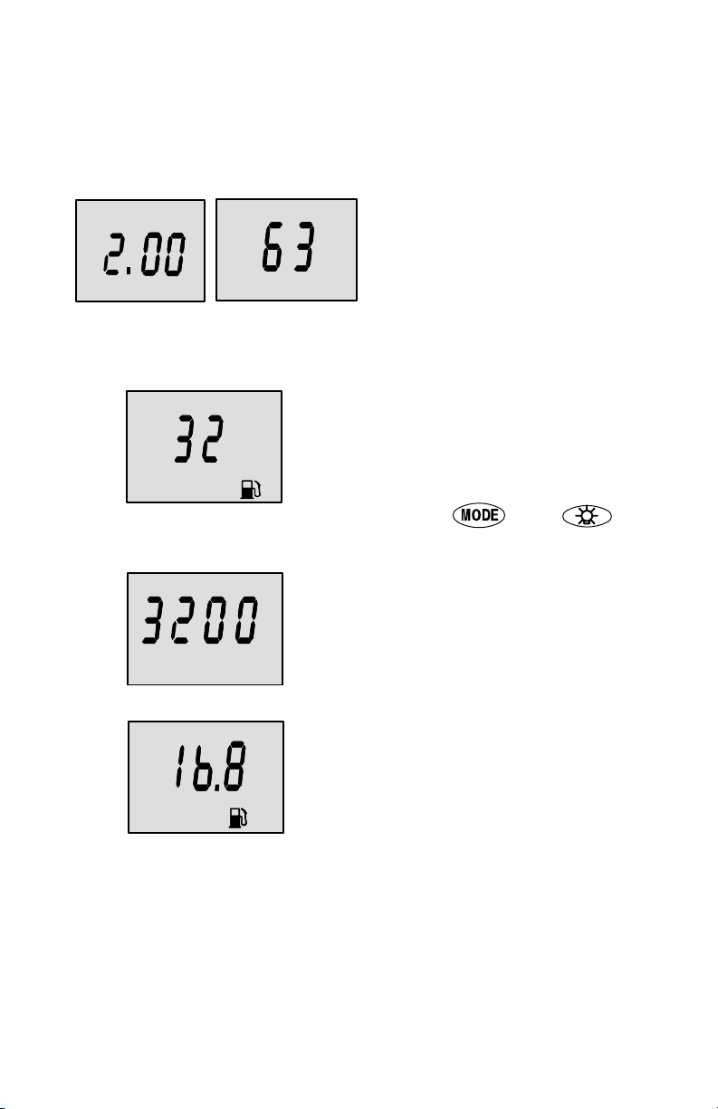
STANDARD DISPLAY SCREENS
NOTE:This manual shows all the Monitor display screens that are
available. Depending on your type of engine, not all these screens
will apply.
Start Up
At start up, a momentary (1
second) screen displays the
Hrs
Software Version Engine Hours
Gal
current monitor software
version, followed by a 4 second
display showing hours of engine
use.
Fuel Used
Displays approximate fuel used
since the last reset. Reset will
return display back to 0.
You can Reset anytime by
pressing and
buttons together momentarily.
RPM
Gal/h
Engine RPM
Tachometer – Displays engine
speed in Revolutions Per
Minute (RPM).
Fuel Flow
Displays current estimated
individual engine fuel
consumption in Gallons per
hour (Gal/hr) or Liters per hour
(Ltr/hr).
(continued on next pge)
7
Page 10

STANDARD DISPLAY SCREENS
TRIM
Psi
Trim Position
Displays trim position of the propulsion unit up to the maximum
trim position, and then displays
the trailer position.
0 = down,
10 = full trim
25 = full trailer.
NOTE: This screen can be set to
pop up whenever the trim switch
is used. Refer to the CAL 1 Calibrations.
Engine Temperature
Displays the engine temperature in degrees Fahrenheit (°F)
or Celsius (°C).
Water Pressure
Displays the engine temperature in degrees Fahrenheit (°F)
or Celsius (°C).
Oil Temperature
Displays the engine oil temperature
in degrees Fahrenheit (°F) or
Celsius (°C).
(continued on next pge)
8
Page 11

STANDARD DISPLAY SCREENS
Oil Pressure
Displays engine oil pressure in Psi
or Bar.
Battery Voltage
Displays voltage level (condition)
Volt
of battery.
Range
Miles
Range
Displays estimated range
based on current fuel consumption and fuel remaining in the
tank that is connected to the
system. The number displayed
is an estimate of the distance
you can travel on the remaining
fuel at current boat speed.
NOTE: Two requirements to activate this screen,
1.You must perform the fuel
tank calibration in CAL 2. Refer
to the CAL 2 Calibrations Section.
2.You must have a speed input
device connected to the system
(paddle wheel or pitot pressure
transducer).
(continued on next pge)
9
Page 12

STANDARD DISPLAY SCREENS
Depth
Ft
MPH
o
Water Depth
Displays the depth of water under the transducer if connected.
NOTE: You must have a depth
transducer (purchased separately) connected to the system in order for this screen to operate.
Vessel Speed
Displays the vessel speed.
Seawater Temperature
Displays the water temperature.
F
10
Page 13

Shallow Water Alarm
You can set an alarm to trigger whenever the boat moves into water
shallower than the alarm level.
Setting Shallow Water Alarm.
1. The water depth screen must be displayed. Be sure Depth is
turned on in CAL 2. Refer to CAL 2 Calibration Section.
2. Press both
and buttons together for 3 seconds.
3. The alarm on or off menu will appear.
4. Press the
button to toggle to ON.
Depth
5. Push button to save.
6. The depth number will be flashing. Press the
button to set
the flashing number to desired alarm depth. 100 ft maximum
depth and 2 ft minimum depth.
Depth
7. Push button to save.
11
Page 14

WARNING SYSTEM
When a problem is detected with the engine, the warning display
screens will alert the operator to the potential problem. Refer to the
Engine Operation, Maintenance and Warranty Manual for
explanation of the problem and the correct action to take.
If problem can cause immediate engine damage, the Engine Guardian
System will respond to the problem by limiting engine power. Immediately reduce throttle speed to idle. Refer to the Engine Operation,
Maintenance and Warranty Manual for further explanation of the
problem and the correct action to take.
If the mode button is pressed to a different screen, the flashing alarm
signal will remain flashing to indicate there still is a problem.
Warning Display Screens
IMPORTANT: Refer to the Engine Operation, Maintenance and
Warranty Manual for further explanation of the problem and the
correct action to take.
Engine Overheat
The Bell and Temperature icons
are displayed. There is insufficient water pressure in the cooling system.
Low Oil Reserve
The bell and oil icons are displayed. The oil level is critically
low in the engine mounted oil
reservoir tank. (Outboard only)
Low Water Pressure
The Bell and Water Pressure
icons are displayed. There is insufficient water pressure in the
cooling system.
(continued on next pge)
12
Page 15

WARNING SYSTEM
Warning Display Screens
IMPORTANT: Refer to the Engine Operation, Maintenance and
Warranty Manual for further explanation of the problem and the
correct action to take.
Water in Fuel
The Bell and Fuel Icon are displayed. Water in the water-separating fuel filter reached the full
level.
Engine Overspeed
The Bell icon is displayed. The
engine speed exceeded the
maximum allowable RPM.
Engine Malfunction
The Bell and Engine Icon will
appear to inform the driver that
an engine problem occurred.
Oil Pump Fault / Low Oil
Pressure
The Bell, Engine and oil icons
are displayed. The oil pump has
stopped functioning electrically.
No lubricating oil is being supplied to the engine.
13
Page 16

CAL 1 CALIBRATION
Cal1 Display Calibrations:
•(On or Off) Trim Pop up Screen
•Trim Calibration
•English or Metric Units Selection
•Range/Distance Units Selection
•(On or Off) Depth, Trim, Engine Temperature, Oil Pressure, Oil
Temperature, Water Pressure, Volts, Engine Hours,Speed, Seawater Temperature and Data Simulator pages.
1. Turn ignition key to the on position.
2. Press and hold
CAL 1 calibration screen.
NOTE:Press and hold
played will open the depth calibration menu.
NOTE:Press and hold
the CAL 1 calibration screen.
and for 3 seconds to bring up the
and when depth screen is dis-
and for 3 seconds to get out of
Cal 1 Start Screen
Press the button to move to the next calibration screen.
Tri
m
Trim Pop-up Screen
(Turn on or off)
Select whether you want the
power trim display screen to pop
up whenever the trim switch is
activated
.
1. Have the number “flashing” on display screen.
2. Press the
1 = on
0 = off
3. Press the
button to select.
button to move to the next function.
14
Page 17

CAL 1 CALIBRATION
Trim
Trim Sensor
0.0 Setting
(Full Trim in Position)
1. The word “Trim” and down arrow should be blinking.
2. Trim unit to the full Down/In position.
3. Press the
4. Press the
button to save.
button to advance to 10.0 setting.
Trim Trim Sensor
10.0 Setting
(Full Trim Out Position)
5. The word “Trim” and down and up arrows should be blinking.
6. Trim unit out to the maximum trim (not trailer) position.
7. Press the
8. Press the
button to save.
button to advance to 25.0 setting.
Trim
Trim Sensor
25.0 Setting
(Full Trailer Out Position)
9. The word “Trim” and up arrow should be blinking.
10. Use the trim switch and trim unit out to the maximum trailer posi-
tion.
11. Press the
12. Press the
button to save.
button to move to the next function.
15
Page 18

CAL 1 CALIBRATION
SAE English System
F
Gal
Psi
Ft
1. Press the
2. Press the
Range
Miles
1. Press the
2. Press the
Metric System
Ltr M
English or Metric
Select whether you want the
C
readings in the SAE English
Bar
system or the Metric system.
button to toggle between units.
button to move to the next function.
Range Readings
Miles
NMiles
Km
button to toggle between units.
button to move to the next function.
Select whether you want the
readings in Miles, Nautical Miles
or Kilometers.
Depth Display
(on or off)
Select whether you want the
depth screen to be displayed.
1. Press the
2. Press the
1. Press the
2. Press the
button to select on or off.
button to move to the next function.
Trim
Trim Display (on or off)
Select whether you want the
trim screen to be displayed.
button to select on or off.
button to move to the next function.
16
Page 19

CAL 1 CALIBRATION
Coolant Temperature
Display (on or off)
Select whether you want the
coolant temperature screen to
be displayed.
1. Press the
2. Press the
button to select on or off.
button to move to the next function.
Oil Pressure Display
(on or off)
Select whether you want the oil
pressure screen to be displayed.
1. Press the
2. Press the
button to select on or off.
button to move to the next function.
Oil Temperature Display (on or off)
Select whether you want the oil
temperature screen to be displayed.(Outboard only)
1. Press the button to select on or off.
2. Press the
button to move to the next function.
17
Page 20

CAL 1 CALIBRATION
Water Pressure Display
(on or off)
Select whether you want the
water pressure screen to be displayed.
1. Press the
2. Press the
1. Press the
2. Press the
Hrs
1. Press the
button to select on or off.
button to move to the next function.
Battery Voltage Display
(on or off)
Volt
button to select on or off.
button to move to the next function.
Select whether you want the
battery voltage screen to be displayed.
Engine Hours Display
(on or off)
Select whether you want the engine hours screen to be displayed.
button to select on or off.
2. Press the
button to move to the next function.
Vessel Speed Display
(on or off)
Select whether you want vessel
speed screen to be displayed.
18
Page 21

1. Press the button to select on or off.
2. Press the
1. Press the
2. Press the
1. Press the
2. Press the
screen .
button to move to the next function.
Seawater Temperature
Display (on or off)
Select whether you want seawater temperature screen to be
displayed.
button to select on or off.
button to move to the next function.
Simulator Display (on
or off)
Select whether you want seawater temperature screen to be
displayed.
button to select on or off.
button to move to the Calibration selection
1. Press and hold
CAL 1 calibration screen or press the
ibration screen.
and for 3 seconds to get out of the
Calibration Selection
Screen
Select between Cal1, Cal2, or to
exit the calibration mode..
to go to CAL 2 cal-
19
Page 22

CAL 2 CALIBRATION
CAL2 Display Calibrations:
•Paddle Wheel Speed Sensor Frequency Setting
•Pitot Water Pressure Speed Sensor Input Setting
•Pitot Water Pressure Speed Sensor Multiplier
•Fuel Tank Calibration
1. Turn ignition key to the on position.
2. Press and hold
CAL 1 calibration screen. Press and hold
for 3 seconds to bring up the CAL 2 calibration screen.
NOTE:Press and hold
the CAL 2 calibration screen.
and for 3 seconds to bring up the
and again
and for 3 seconds to get out of
Cal 2 Start Screen
Press the button to move to the next calibration screen.
Pitot Water Pressure
Sensor Input
Select the pressure input of the
Pitot water pressure sensor on
the engine.
NOTE:The standard speed input on production Mercury Outboards is 100 PSI. Certain High
Performance applications may
require a 200 PSI input.
1. Press the
0 =No Pitot pressure sensor
1 = 100 PSI
2 = 200 PSI
2. Press the
button to select.
button to move to the next function.
20
Page 23

CAL 2 CALIBRATION
Paddle Wheel Speed
Sensor Frequency
Frequency can be changed to
Miles
match requirements of different
sensors. 4.9 is the frequency of
the paddle wheel speed sensor
provided by Mercury Marine.
Press the
Press the
Press the
button to save and move to the next function.
Seawater Temperature
Display (on or off)
Indicates if a seawater temperature sensor is installed.
NOTE: You must have a Mercury paddlewheel or depth/temp
transducer (purchased separately) connected to the system
in order for this screen to operate .
button to save and move to the next function.
Pitot Multiplier Screen
Allows you to adjust the
speedometer value to match
another speedometer, such as
a GPS.
NOTE: The multiplier ranges
from 0.5 to 1.5.
button to save and move to the next function.
21
Page 24

CAL 2 CALIBRATION
Fuel Tank Calibration
THERE ARE THREE METHODS TO SET UP THE FUEL TANK
LEVEL MONITORING FEATURE:
First: Do nothing. Linear readout based on raw sensor values. This
mode does not factor in irregular tank shapes.
Second: By following the tank calibration default procedure, which
is done without actually adding fuel to the tank. The Monitor will supply an estimated range value based on default sensor values. This
mode does not factor in irregular tank shapes.
Third: By following the tank calibration procedure completely, which
includes adding fuel at certain calibration points. Monitor will display
an estimated range value that factors in the tank shape.
22
Page 25

CAL 2 CALIBRATION
CAL 2 Calibration
Tank 1 (fuel) Capacity
Setting
“t1” = tank 1
1. Press the button until “t1” is displayed. “t1” = tank 1.
2. Press
displayed.
NOTE:The word “no” will not go away unless the gauge sees a tank
connected to the system. With no tank connected, you will not be able
to enter a capacity.
3. Enter the capacity of tank 1 in gallons/liters using the
4. Press the
tion.
once more. The word “no” and the fuel icon will be
key.
button to save and move to the next func-
Tank 2 Capacity Setting
NOTE:Tank 2 does not have to
be a fuel tank. It could represent
an oil tank for example.
“t2” = tank 2
1. Press the button until “t2” is displayed. “t2” = tank 2.
2. Press
displayed.
NOTE:The word “no” will not go away unless the gauge sees a tank
connected to the system. With no tank connected, you will not be able
to enter a capacity.
once more. The word “no” and the fuel icon will be
3. Enter the capacity of tank 2 in gallons using the
4. Press the
tion.
button to save and move to the next func-
23
key.
Page 26

CAL 2 CALIBRATION
Tank 1 Calibration
Once the capacities have been
entered, you need to select
whether you want to calibrate
fuel tank 1 ” ’t1”.
NOTE: The gauge will not let you
calibrate the fuel tank until the capacity had been entered).
1. Press the
then press
button to select 1= on, 0 = off. Selecting “1” and
to continue fuel tank calibration.
Tank 1 Calibration 0%
Setting
Have the fuel tank level at
empty.
2. Press the
vance to 25% setting.
Gal
button to save. Press the button to ad-
Tank 1 Calibration 25%
Setting
Gal
25 Percent Fuel to Add
3. Add the displayed amount of fuel to the fuel tank.
4. Press the
vance to 50% setting.
button to save. Press the button to ad-
Adding the amount of fuel shown
will raise fuel tank level to 25 percent.
NOTE:The quantity of “Fuel to
Add” is determined by the fuel
tank capacity number entered.
24
Page 27

CAL 2 CALIBRATION
Tank 1 Calibration 50%
Setting
Gal
50 Percent
5. Add the displayed amount of fuel to the fuel tank.
Fuel to Add
Adding the amount of fuel shown
will raise fuel tank level to 50 percent.
NOTE:The quantity of “Fuel to
Add” is determined by the fuel
tank capacity number entered.
6. Press the
vance to 75% setting.
button to save. Press the button to ad-
Tank 1 Calibration 75%
Setting
Gal
75 Percent
7. Add the displayed amount of fuel to the fuel tank.
8. Press the
vance to full% setting.
Fuel to Add
button to save. Press the button to ad-
Adding the amount of fuel shown
will raise fuel tank level to 75 percent.
NOTE:The quantity of “Fuel to
Add” is determined by the fuel
tank capacity number entered.
Tank 1 Calibration Full
Setting
Gal
Full Percent
9. Add the amount of fuel to fill the fuel tank.
Fuel to Add
Add the amount of fuel to fill the
fuel tank.
10. Press the
vance to next function.
button to save. Press the button to ad-
25
Page 28

CAL 2 CALIBRATION
Tank 2 Calibration
Select whether you want to calibrate tank 2.
NOTE: Tank 2 does not have to
be a fuel tank. It could represent
an oil tank for example.
NOTE: The gauge will not let you
calibrate the tank until the capacity had been entered).
1. Press the
2. Press the
continue tank 2 calibration.
3. Press the
button until “t2” is displayed. “t2” = tank 2.
button to select 1= on, 0 = off. Selecting “1” will
button to continue.
Tank 2 Calibration Icon
Selection
Select one of three icons for
tank 2 display screen. (oil, water/waste, fuel).
1. Press the
button, select which icon you want tank 2 to be, (oil, fuel,
or water/waste).
NOTE:If you choose oil or water/waste icon, no further tank 2 calibration will be needed. If tank 2 will be for fuel, continue tank 2 procedure.
2. Press the
button, you will see a blinking icon. Using the
button to continue.
Tank 2 Calibration 0%
Setting
Gal
Have the fuel tank level at
empty.
3. Press the
vance to 25% setting.
button to save. Press the button to ad-
26
Page 29

CAL 2 CALIBRATION
Tank 2 Calibration 25%
Setting
Gal
25 Percent Fuel to Add
4. Add the displayed amount of fuel to the fuel tank.
Adding the amount of fuel shown
will raise fuel tank level to 25 percent.
NOTE :The quantity of fuel to add
is determined by the fuel tank capacity number entered.
5. Press the
vance to 50% setting.
button to save. Press the button to ad-
Tank 2 Calibration 50%
Setting
Gal
50 Percent
6. Add the displayed amount of fuel to the fuel tank.
7. Press the
vance to 75% setting.
Fuel to Add
button to save. Press the button to ad-
Adding the amount of fuel shown
will raise fuel tank level to 50 percent.
NOTE:The quantity of fuel to add
is determined by the fuel tank capacity number entered.
27
Page 30

CAL 2 CALIBRATION
Tank 2 Calibration 75%
Setting
Gal
75 Percent
8. Add the displayed amount of fuel to the fuel tank.
Fuel to Add
Adding the amount of fuel shown
will raise fuel tank level to 75 percent.
NOTE:The quantity of fuel to add
is determined by the fuel tank capacity number entered.
9. Press the
vance to full% setting.
button to save. Press the button to ad-
Tank 2 Calibration Full
Setting
Gal
Full Percent Fuel to Add
10. Add the amount of fuel to fill the fuel tank.
11. Press and hold
CAL 2 calibration screen.
and for 3 seconds to get out of the
Add the amount of fuel to fill the
fuel tank.
28
 Loading...