

Page 1

SERVICE
MAIN MENU
MANUAL
Number 14
Sterndrive Units
Printed in U.S.A. 90-818177-3 APRIL 2001
Alpha One
Generation II
2001, Mercury Marine
Page 2

MerCruiser #14 Sterndrive Units
90-818177-3
MerCruiser #14 Sterndrive Units
90-818177-3
90- i
Page 3

SERVICE MANUAL NUMBER 14
INDEX
GENERAL INFORMATION
IMPORTANT INFORMATION
Section 1A - General Information
Table of Contents
How To Use This Manual 1A-2. . . . . . . . . . . . .
Page Numbering 1A-2. . . . . . . . . . . . . . . . .
Introduction 1A-3. . . . . . . . . . . . . . . . . . . . . . . .
Special Product Information 1A-3. . . . . . . .
Directional References 1A-3. . . . . . . . . . . . . . .
Propeller Rotation 1A-4. . . . . . . . . . . . . . . . . . .
Serial Number Locations and
Engine Designation Decal 1A-4. . . . . . . . . . .
Sterndrive Unit Serial Number
Location 1A-5. . . . . . . . . . . . . . . . . . . . . . . .
1
A
Decal Application 1A-5. . . . . . . . . . . . . . . . . . .
Decal Removal 1A-5. . . . . . . . . . . . . . . . . . .
Instructions for “Wet” Application 1A-5. . .
Painting Procedures 1A-7. . . . . . . . . . . . . . . . .
Cleaning & Painting Aluminum
Propellers & Gear Housings 1A-7. . . . . . .
90-818177--3 APRIL 2001 Page 1A-1
Page 4
GENERAL INFORMATION SERVICE MANUAL NUMBER 14
INDEX
How To Use This Manual
This Manual is divided into sections which represent major components and systems.
Some sections are further divided into parts which more fully describe the component.
Sections and parts are listed at the front of this manual.
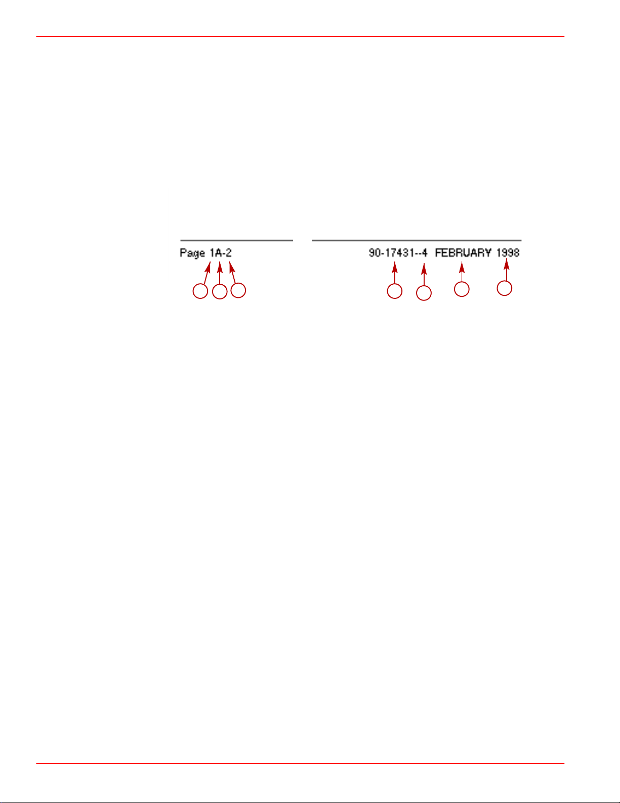
Page Numbering
Two number groups appear at the bottom of each page. Following is an example and
description.
a
a- Section Number
b- Section Part
c- Page Number
d- Manual Part Number
e- Revision Number
f-Month Printed
g- Year Printed
c
b
d
e
f
g
Page 1A-2 90-818177--3 APRIL 2001
Page 5
SERVICE MANUAL NUMBER 14
INDEX
Introduction
This comprehensive overhaul and repair manual is designed as a service guide for the
Mercury MerCruiser models previously listed. It provides specific information, including
procedures for disassembly, inspection, assembly and adjustment, to enable dealers and
service mechanics to repair these products.
Before attempting repairs, it is suggested that the procedure be read to gain knowledge of
the methods and tools used and the cautions and warnings required for safety.
Special Product Information
During production of these models, special product improvements and changes have been
made to increase product reliability and performance. Such changes to a sterndrive
assembly component(s) are covered in the “Special Information” portion of the appropriate
sterndrive assembly section. (Refer to the section “Index”.) Serial number breaks are
provided, where applicable, for ease of identification.
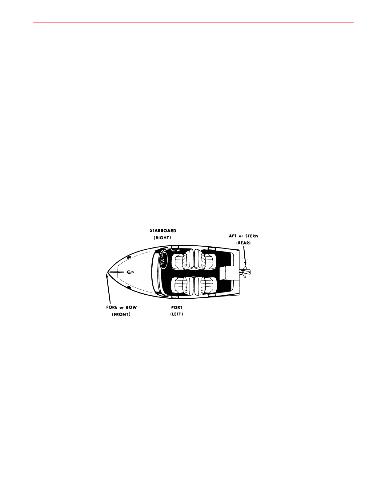
Directional References
Front of boat is bow; rear is stern. Starboard side is right side; port side is left side. In this
service manual, all directional references are given as they appear when viewing boat from
stern, looking toward bow.
GENERAL INFORMATION
90-818177--3 APRIL 2001 Page 1A-3
Page 6
GENERAL INFORMATION SERVICE MANUAL NUMBER 14
INDEX
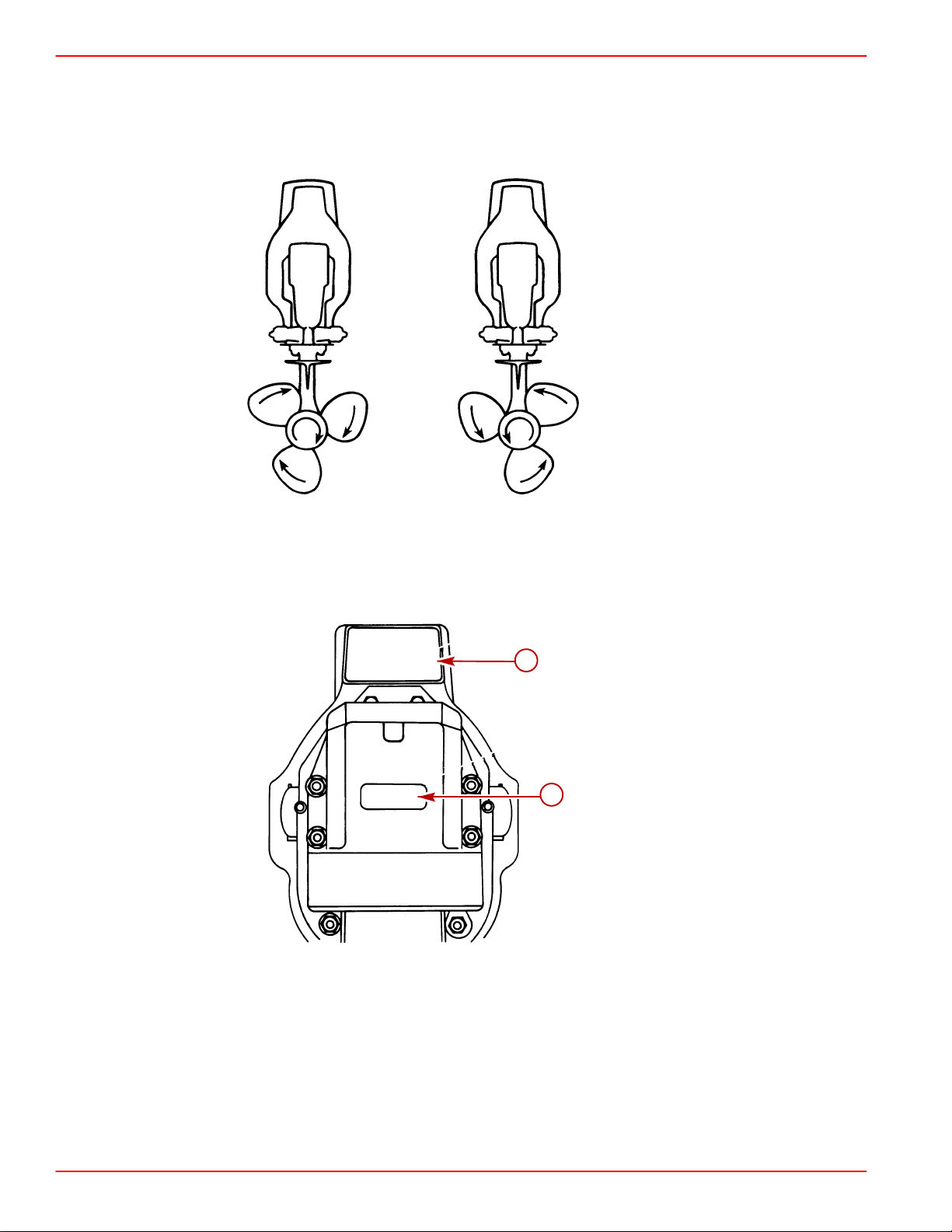
Propeller Rotation
Propeller rotation for sterndrive can be right hand or left hand rotation as viewed from the
aft end of the propeller.
Right Hand Rotation Left Hand Rotation
Serial Number Locations and Engine Designation Decal
a
b
a-Transom Assembly Serial Number
b-Engine Designation Decal
22031
Page 1A-4 90-818177--3 APRIL 2001
Page 7
SERVICE MANUAL NUMBER 14
INDEX
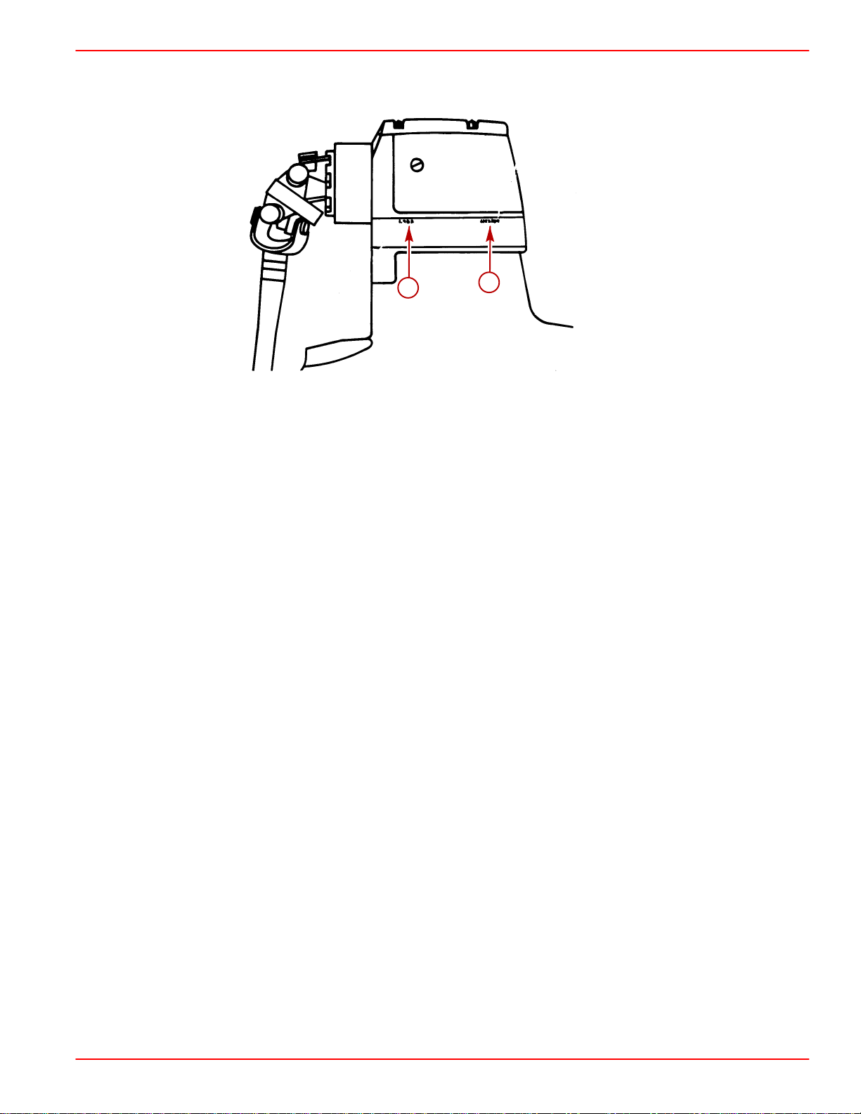
Sterndrive Unit Serial Number Location
GENERAL INFORMATION
Sterndrive Unit Serial Number Location - Port Decal
(Also Located Under Decal On Housing)
a-Sterndrive Unit Serial Number
b-Sterndrive Unit Gear Ratio
Decal Application
Decal Removal
1. Mark decal location before removal to assure proper alignment of new decal.
2. Carefully soften decal and decal adhesive with a heat gun or heat blower while removing
old decal.
3. Clean decal contact area with a 1:1 mixture of isopropyl alcohol and water.
b
a
22026
4. Thoroughly dry decal contact area and check for a completely cleaned surface.
Instructions for “Wet” Application
NOTE: The following decal installation instructions are provided for a “Wet” installation. All
decals should be applied wet.
TOOLS REQUIRED
1. Plastic Squeegee*
2. Stick Pin
3. Dish Washing Liquid/Detergent without ammonia** “Joy” and “Drift” are compatible
for this process.
** Automotive Body Filler Squeegee
** Do not use a soap that contains petroleum based
solvents.
90-818177--3 APRIL 2001 Page 1A-5
Page 8

GENERAL INFORMATION SERVICE MANUAL NUMBER 14
INDEX
SERVICE TIP: Placement of decals using the “Wet” application will allow time to
position decal. Read entire installation instructions on this technique before
proceeding.
TEMPERATURE
IMPORTANT: Installation of vinyl decals should not be attempted while in direct
sunlight. Air and surface temperature should be between 60°F (15°C) and 100°F
(38°C) for best application.
SURFACE PREPARATION
IMPORTANT: Do not use a soap or any petroleum based solvents to clean application
surface.
Clean entire application surface with mild dish washing liquid and water. Rinse surface
thoroughly with clean water.
DECAL APPLICATION
1
1. Mix
/2 ounce (16 ml) of dish washing liquid in one gallon (4 l) of cool water to use as
wetting solution.
NOTE: Leave protective masking, if present, on the face of decal until final steps of decal
installation. This will ensure that the vinyl decal keeps its shape during installation.
2. Place the decal face down on a clean work surface and remove the paper backing from
“adhesive side” of decal.
3. Using a spray bottle, flood the entire “adhesive side” of the decal with the pre-mixed
wetting solution.
4. Flood area where the decal will be positioned with wetting solution.
5. Position pre-wetted decal on wetted surface and slide into position.
6. Starting at the center of the decal, “lightly” squeegee out the air bubbles and wetting
solution with overlapping strokes to the outer edge of the decal. Continue going over the
decal surface until all wrinkles are gone and adhesive bonds to the cowl surface.
7. Wipe decal surface with soft paper towel or cloth.
8. Wait 10 - 15 minutes.
9. Starting at one corner, “carefully and slowly” pull the masking off the decal surface at
a 180° angle.
NOTE: To remove any remaining bubbles, pierce the decal at one end of the bubble with
stick pin and press out the entrapped air or wetting solution with your thumb (moving toward
the puncture).
Page 1A-6 90-818177--3 APRIL 2001
Page 9

SERVICE MANUAL NUMBER 14
INDEX
Painting Procedures
Cleaning & Painting Aluminum Propellers & Gear Housings
WARNING
Avoid serious injury from flying debris. Avoid serious injury from airborne
particles. Use eye and breathing protection with proper ventilation.
PROPELLERS
1. Sand the entire area to be painted with 3M 120 Regalite Polycut or coarse Scotch-Brite,
disc or belts.
2. Feather edges of all broken paint edges. Try not to sand through the primer.
3. Clean the surface to be painted using PPG Industries DX330 Wax and Grease Remover
or equivalent (Xylene or M.E.K.).
4. If bare metal has been exposed, use Quicksilver’s Light Gray Primer.
5. Allow a minimum of 1 hour dry time and no more than 1 week before applying the finish
coat.
6. Apply the finish coat using Quicksilver ’s EDP Propeller Black.
GENERAL INFORMATION
GEAR HOUSINGS
The following procedure should be used in refinishing gear housings. This procedure will
provide the most durable paint system available in the field. The materials recommended
are of high quality and approximate marine requirements. The following procedure will
provide a repaint job that compares with a properly applied factory paint finish. It is
recommended that the listed materials be purchased from a local Ditzler Automotive Finish
Supply Outlet. The minimum package quantity of each material shown is sufficient to
refinish several gear housings.
Procedure:
1. Wash gear housing with a muriatic acid base cleaner to remove any type of marine
growth, and rinse with water, if necessary.
2. Wash gear housing with soap and water, then rinse.
3. Sand blistered area with 3M 180 grit sandpaper or P180 Gold Film Disc to remove paint
blisters only. Feather edge all broken paint edges.
4. Clean gear housing thoroughly with (DX-330) wax and grease remover.
5. Spot repair surfaces where bare metal is exposed with (DX-503) alodine treatment.
IMPORTANT: Do not use any type of aerosol spray paints as the paint will not properly
adhere to the surface nor will the coating be sufficiently thick to resist future paint
blistering.
6. Mix epoxy chromate primer (DP-40) with equal part catalyst (DP-401) per
manufacturers instructions, allowing proper induction period for permeation of the
epoxy primer and catalyst.
IMPORTANT: Do not paint sacrificial zinc trim tab or zinc anode.
7. Cut out a cardboard “plug” for trim pump pocket to keep paint off of mating surface to
maintain good continuity circuitry between trim tab and gear housing.
90-818177--3 APRIL 2001 Page 1A-7
Page 10

GENERAL INFORMATION SERVICE MANUAL NUMBER 14
INDEX
8. Allow a minimum of one hour drying time and no more than one week before top coating
assemblies.
9. Use Ditzler Urethane DU9000 for Mercury Black and DU33414M for Sea Ray White.
Catalyze the colors with Ditzler DU5 catalyst mixed 1:1 ratio. Reduce with solvents per
Ditzler label.
CAUTION
Be sure to comply with instructions on the label for ventilation and respirators.
Using a spray gun, apply one half to one mil even thickness. Let dry, flash off for
five minutes and apply another even coat of one half to one mil film thickness. This
urethane paint will dry to the touch in a matter of hours, but will remain sensitive
to scratches and abrasions for a few days.
10. The type of spray gun used will determine the proper reduction ratio of the paint.
Page 1A-8 90-818177--3 APRIL 2001
Page 11

SERVICE MANUAL NUMBER 14
INDEX
GENERAL INFORMATION
THIS PAGE IS INTENTIONALLY BLANK
90-818177--3 APRIL 2001 Page 1A-9
Page 12

GENERAL INFORMATION SERVICE MANUAL NUMBER 14
INDEX
THIS PAGE IS INTENTIONALLY BLANK
Page 1A-10 90-818177--3 APRIL 2001
Page 13

SERVICE MANUAL NUMBER 14
MAINTENANCE
IMPORTANT INFORMATION
Section 1B - Maintenance
Table of Contents
Trim Pump Specifications 5A-2. . . . . . . . . . . .
Valve Pressure Specifications 5A-2. . . . . .
Maintenance Schedules 1B-2. . . . . . . . . . . . . .
Maintenance Intervals 1B-2. . . . . . . . . . . . .
Gas Sterndrive 1B-2. . . . . . . . . . . . . . . . . . . . . .
Routine Maintenance * 1B-2. . . . . . . . . . . .
Scheduled Maintenance * 1B-3. . . . . . . . . .
Quicksilver Maintenance Products 1B-4. . . . .
Lubricating Shift Cable Pivot Points 1B-4. . . .
Lubricating Propeller Shaft 1B-4. . . . . . . . . . .
Lubricating Steering System 1B-5. . . . . . . . . .
Power Steering Models 1B-5. . . . . . . . . . . .
Manual Steering Models 1B-5. . . . . . . . . . .
Lubricating Tie Bar Pivot Points 1B-6. . . . . . .
Models With Control Valve Mounted
On Starboard Transom Assembly 1B-6. .
Models With Control Valve Mounted
On Port Transom Assembly 1B-6. . . . . . .
Lubricating Transom and Gimbal
Assembly ,Hinge Pins and Gimbal Bearing . . . .
1B-7
Checking and Adding Sterndrive Oil 1B-8. . .
Models Without Drive Unit Gear
Lube Monitor 1B-8. . . . . . . . . . . . . . . . . . . .
Models With Gear Lube Monitor 1B-9. . . .
1
B
Checking Lubricant for Water 1B-10. . . . . . .
Changing Lubricant 1B-12. . . . . . . . . . . . . . .
General Maintenance 1B-14. . . . . . . . . . . . . . . .
Maintaining Power Package
Exterior Surfaces 1B-14. . . . . . . . . . . . . . . .
Steering Head and Remote
Control Maintenance 1B-14. . . . . . . . . . . . .
Checking Quicksilver MerCathode
System 1B-14. . . . . . . . . . . . . . . . . . . . . . . . .
Maintaining Anodic Trim Tab or
Plate 1B-14. . . . . . . . . . . . . . . . . . . . . . . . . . .
Checking Optional Quicksilver
Anti-Corrosion Anode Kit 1B-14. . . . . . . . . .
Boat Bottom Care 1B-15. . . . . . . . . . . . . . . .
Antifouling Paint 1B-15. . . . . . . . . . . . . . . . . .
Maintaining Ground Circuit
Continuity 1B-15. . . . . . . . . . . . . . . . . . . . . . .
Power Package Layup (Out of
Season Storage) 1B-16. . . . . . . . . . . . . . . . . . .
Engine 1B-16. . . . . . . . . . . . . . . . . . . . . . . . . .
Sterndrive 1B-16. . . . . . . . . . . . . . . . . . . . . . .
Power Package Recommissioning 1B-18. . . . .
Engine 1B-18. . . . . . . . . . . . . . . . . . . . . . . . . .
Sterndrive 1B-18. . . . . . . . . . . . . . . . . . . . . . .
90-818177--3 APRIL 2001 Page 1B-1
Page 14
MAINTENANCE SERVICE MANUAL NUMBER
Maintenance Schedules
Maintenance Intervals
Maintenance intervals and the tasks to be performed, as shown in this current schedule, or
as found in a previously printed schedules, are generally based on an average boating
application and environment. However, individual operating habits and personal
maintenance preferences can have an impact on the suggested intervals. In consideration
of these factors, Mercury MerCruiser has adjusted some maintenance intervals and
corresponding tasks to be performed. In some cases, this may allow for more individual
tasks to be performed in a single visit to the serving dealer, rather than multiple visits.
Therefore, it is very important that the boat owner and servicing dealer discuss the current
Maintenance Schedule and develop appropriate maintenance intervals to coincide with the
individual operating habits, environment, and maintenance requirements.
CAUTION
Always disconnect battery cables from battery BEFORE working around electrical
systems components to prevent injury to yourself and damage to electrical system
should a wire be accidentally shorted.
Gas Sterndrive
Routine Maintenance *
Each Day Start Each Day End Weekly
Check crankcase oil (interval can be extended based on experience).
If operating in salt, brackish or polluted waters, flush cooling system after each use.
Check drive unit oil level, trim pump oil level and power steering pump fluid level.
Check water pickups for debris or marine growth. Check water strainer and clean. Check coolant level.
Inspect drive unit anodes and replace if 50 percent eroded.
Inspect fuel pump sight tube and have pump replaced if fuel is present.
Check battery connections and fluid level.
Lubricate propeller shaft and the retorque nut (if operating in only freshwater, this maintenance may be
extended to every four months).
Operating in Saltwater Only: treat engine surface with corrosion guard.
Every Two
Months
* Only perform maintenance which applies to your particular power package.
Page 1B-2 90-818177--3 APRIL 2001
Page 15

SERVICE MANUAL NUMBER 14
Gas Sterndrive (Continued)
Scheduled Maintenance *
MAINTENANCE
Annually
Every 100
Hours or Annu-
ally
Every 200
Hours or 3
Years
Every 300
Hours or 3
Years
Every 2 Years Every 5 Years
Touch-up paint power package and spray with corrosion guard.
Change crankcase oil and filter.
Change drive unit oil and retorque connection of gimbal ring to steering shaft.
Replace fuel filter.
Check steering system and remote control for loose, missing or damaged parts. Lubricate cables and
linkages.
Inspect U-joints, splines and bellows. Check clamps. Check engine alignment. Lubricate U-joint splines.
Lubricate gimbal bearing and engine coupler.
Check continuity circuit for loose or damaged connections. Test MerCathode unit output on Bravo models.
Retorque engine mounts.
Check spark plugs, wires, distributor cap and ignition timing. Check and adjust idle speed.
Clean flame arrestor and crankcase ventilation hoses. Replace PCV valve.
Check electrical system for loose, damaged or corroded fasteners.
Inspect condition and tension of belts.
Check cooling system and exhaust system hose clamps for tightness. Inspect both systems for damage
or leaks.
Disassemble and inspect seawater pump and replace worn components.
Clean seawater section of closed cooling system. Clean, inspect and test pressure cap.
Replace coolant.
* Only perform maintenance which applies to your particular power package.
Whichever occurs first.
Lubricate engine coupler every 50 hours if operated at idle for prolonged periods of time.
Interval will be reduced if not using extended life coolant.
90-818177--3 APRIL 2001 Page 1B-3
Page 16

MAINTENANCE SERVICE MANUAL NUMBER
Quicksilver Maintenance Products
We recommend the use of Quicksilver Maintenance Products where specified.
Lubricating Shift Cable Pivot Points
a
22245
a-SAE 20 Or 30 Engine Oil
Lubricating Propeller Shaft
a
70134
a-Special Lubricant 101, 2-4-C Marine Lubricant With Teflon Or Perfect Seal With
Teflon (Listed In Order Of Effectiveness)
Page 1B-4 90-818177--3 APRIL 2001
Page 17
SERVICE MANUAL NUMBER 14
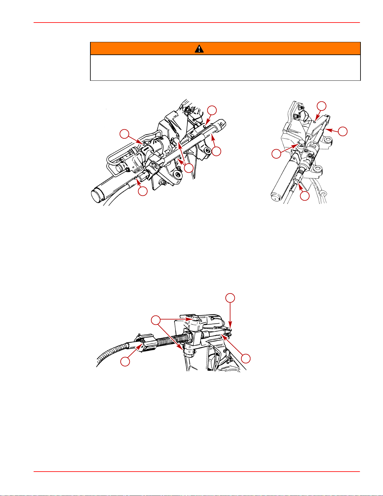
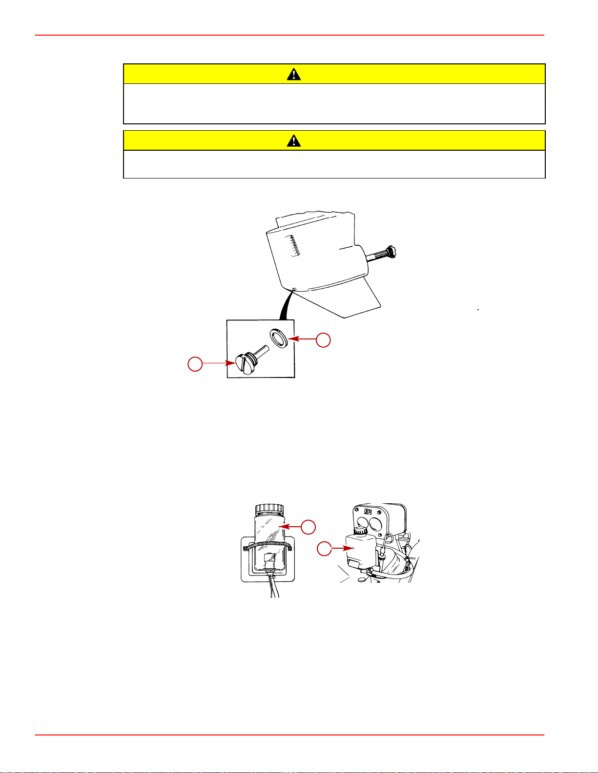
Lubricating Steering System
Transom end of steering cable MUST BE fully retracted into cable housing when
lubricating cable. If cable is lubricated while extended, hydraulic lock of cable could
occur.
Power Steering Models
MAINTENANCE
WARNING
b
Earlier Style Control Valve Later Style Control Valve
a-Steering Cable Grease Fitting - 2-4-C Marine Lubricant With Teflon
b-Control Valve Grease Fitting - 2-4-C Marine Lubricant With Teflon
c-Steering Cable End - Special Lubricant 101
d-Pivot Point - Sae 20 Or 30 Engine Oil
e-Pivot Bolts - Special Lubricant 101
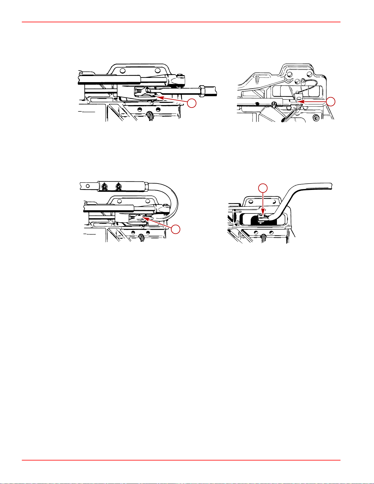
Manual Steering Models
d
d
c
c
e
e
a
22023
a
71901
c
d
a
a-Steering Cable Grease Fitting - 2-4-C Marine Lubricant With Teflon
b-Steering - Cable End And Exposed Portion - Special
Lubricant 101
c-Pivot Points - SAE 20 Or 30 Engine Oil
d-Pivot Bolts - Special Lubricant 101
90-818177--3 APRIL 2001 Page 1B-5
b
22055
Page 18
MAINTENANCE SERVICE MANUAL NUMBER
Lubricating Tie Bar Pivot Points
Models With Control Valve Mounted On Starboard Transom Assembly
a
22079
Starboard Engine Port Engine
a-SAE 20 Or 30 Engine Oil
Models With Control Valve Mounted On Port Transom Assembly
a
a
22079
Port Engine Starboard Engine
a-SAE 20 Or 30 Engine Oil
a
22079
22079
Page 1B-6 90-818177--3 APRIL 2001
Page 19
SERVICE MANUAL NUMBER 14
MAINTENANCE
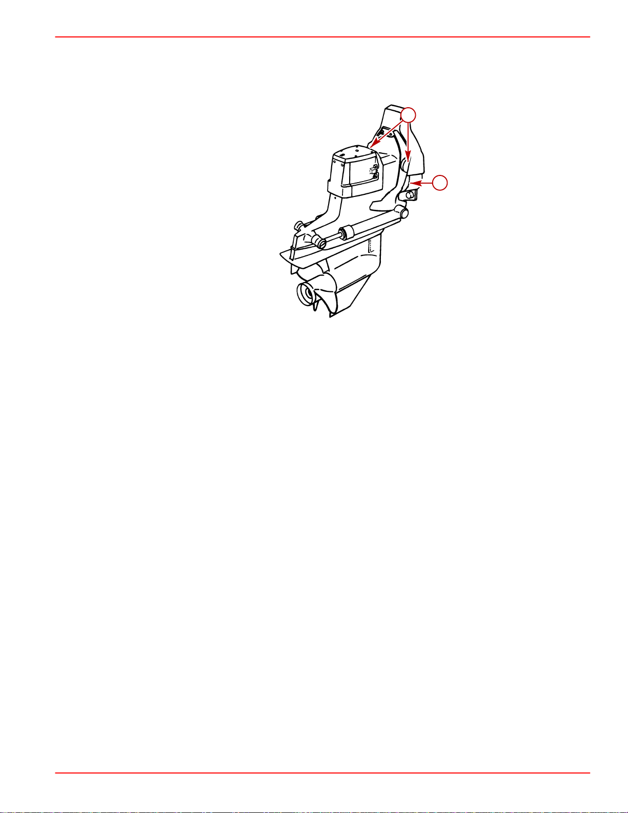
Lubricating Transom and Gimbal Assembly ,Hinge Pins and
Gimbal Bearing
a
b
50072
a-Hinge Pins (One On Each Side)
b-Gimbal Bearing Grease Fitting - Quicksilver U-Joint And Gimbal Bearing
Grease
90-818177--3 APRIL 2001 Page 1B-7
Page 20
MAINTENANCE SERVICE MANUAL NUMBER
Checking and Adding Sterndrive Oil
IMPORTANT: Position sterndrive unit in DOWN/IN position so that anti-ventilation
plate is level.
Models Without Drive Unit Gear Lube Monitor
CAUTION
On models with Gear Lube Monitor, that have a dipstick in driveshaft housing cover:
DO NOT REMOVE DIPSTICK - DO NOT CHECK OIL LEVEL WITH DIPSTICK. Removal
of dipstick results in oil level raising/overfill condition, which can cause oil seal
damage; if left open, drive unit will overflow.
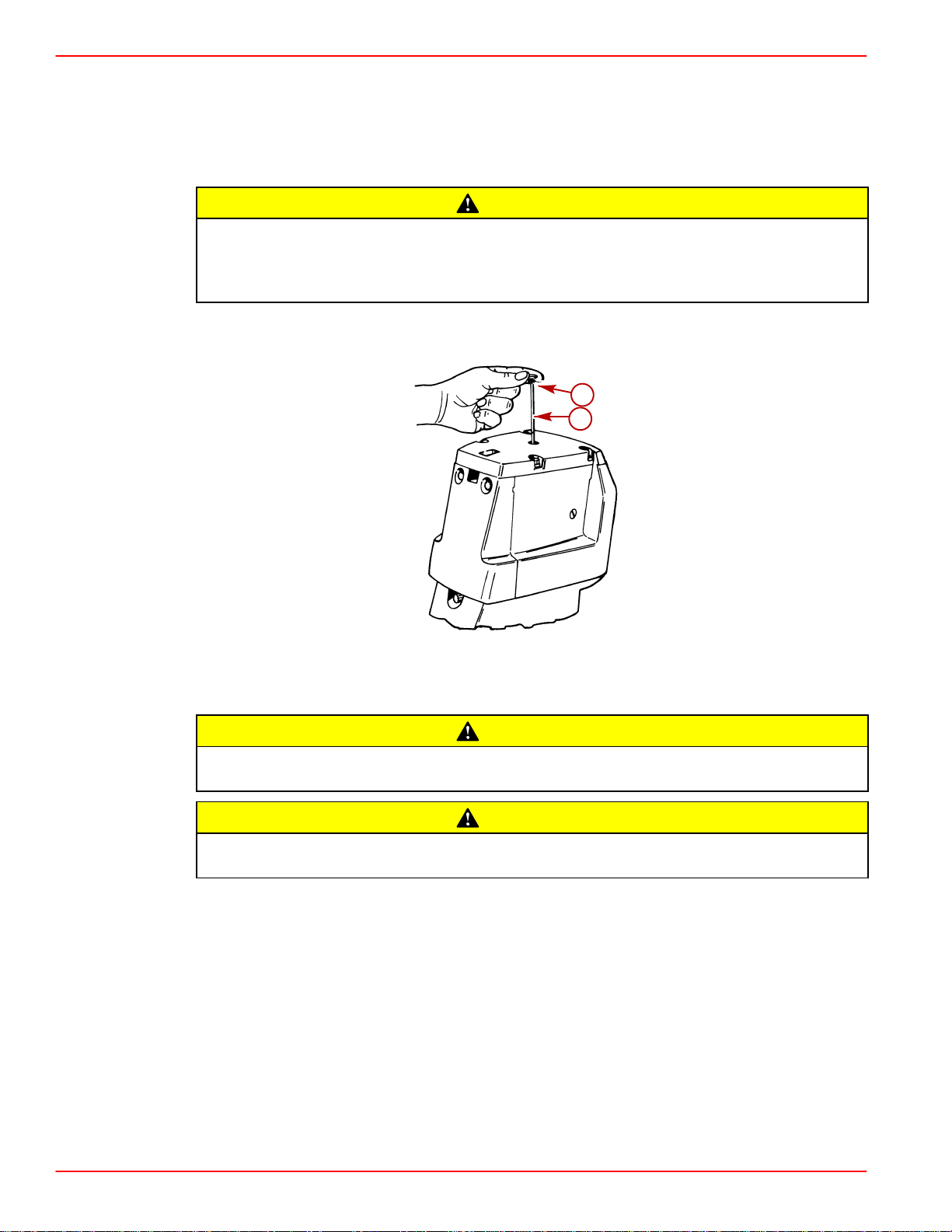
1. Check oil level - oil should come up to line on dipstick. If oil is at proper level, reinstall oil
dipstick and sealing washer. If oil is low, proceed to Step 2.
b
a
22098
a-Oil Dipstick
b-Sealing Washer (On Threads)
CAUTION
DO NOT attempt to fill drive unit through oil vent hole, as air will be trapped in drive
unit and unit will be damaged from lack of lubrication.
CAUTION
If more than 2 fl. oz. (59 ml) of oil is required to fill drive unit, an oil leak may exist.
Find and correct cause of leak before unit is placed in operation.
2. If oil level is low, reinstall dipstick; then, remove oil fill/drain plug and insert lubricant
pump into oil fill/drain hole.
Page 1B-8 90-818177--3 APRIL 2001
Page 21
SERVICE MANUAL NUMBER 14
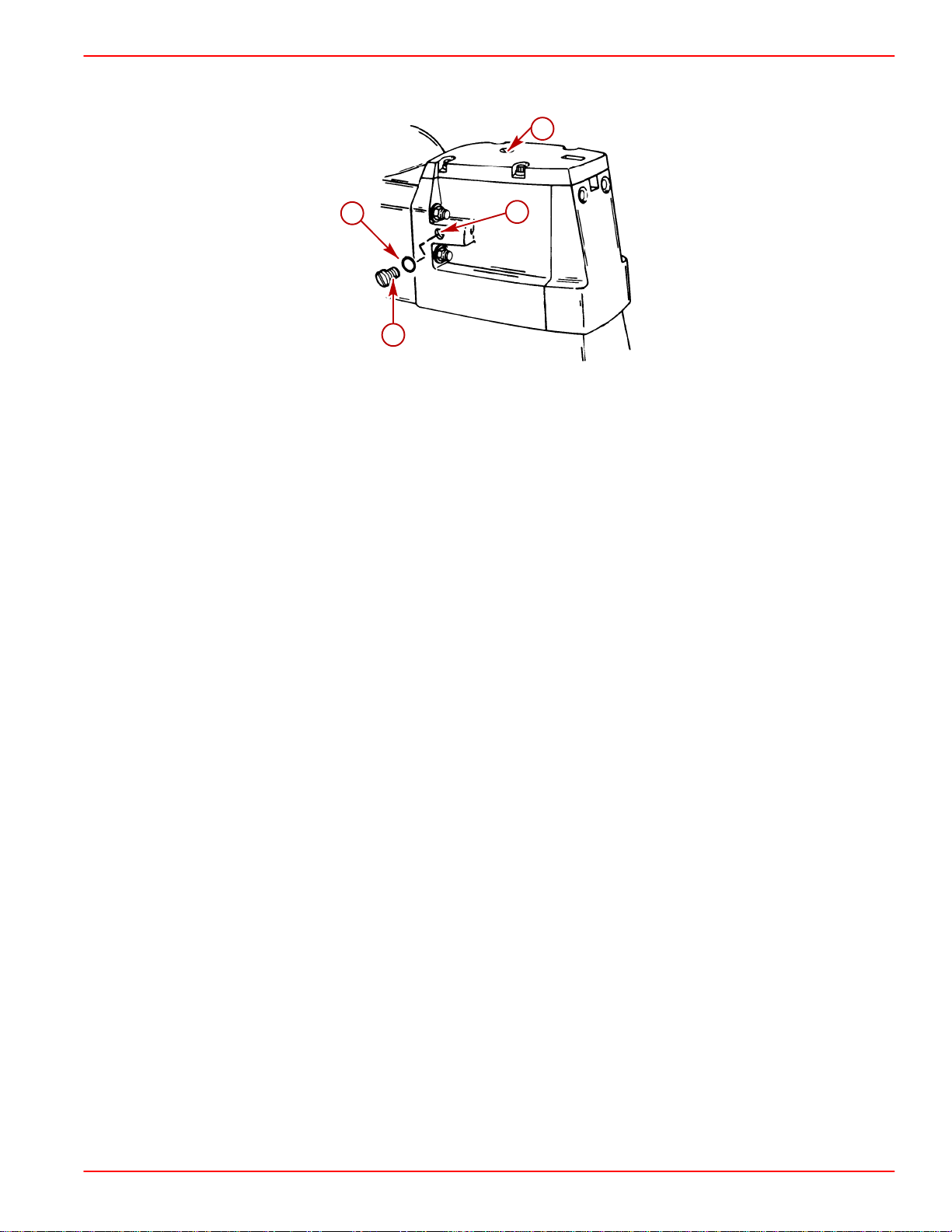
3. Remove oil vent plug; then, fill drive unit (through oil fill/drain unit hole) with oil until an
air-free stream of oil flows out of oil vent hole.
a
a-Oil Vent Plug
b-Sealing Washer Or O-ring
c-Oil Fill/Drain Plug
d-Sealing Washer Or O-ring
22101
MAINTENANCE
b
22095
d
c
22101
22103
4. Without removing lubricant pump from fill/drain hole, reinstall vent plug and sealing
washer (or O-ring if equipped). Torque to 40 lb-in. (4 Nm).
5. Remove lubricant pump and quickly reinstall fill/drain plug and sealing washer (or O-ring
if equipped). Torque to 40 lb-in. (4 Nm).
6. Recheck oil level, using dipstick.
Models With Gear Lube Monitor
IMPORTANT: Position drive unit in DOWN/IN position, verify that the anti-ventilation
plate is level.
NOTE: Drive unit oil level is checked at gear lube monitor.
Gear Lube
Monitor
decal
IMPORTANT: Oil level in gear lube monitor will rise and fall during drive operation;
always check oil level when drive is cool and engine is shut down.
50323
a
b
50028
a-Round Gear Lube Monitor
b-Square Gear Lube Monitor
90-818177--3 APRIL 2001 Page 1B-9
71990
Page 22
MAINTENANCE SERVICE MANUAL NUMBER
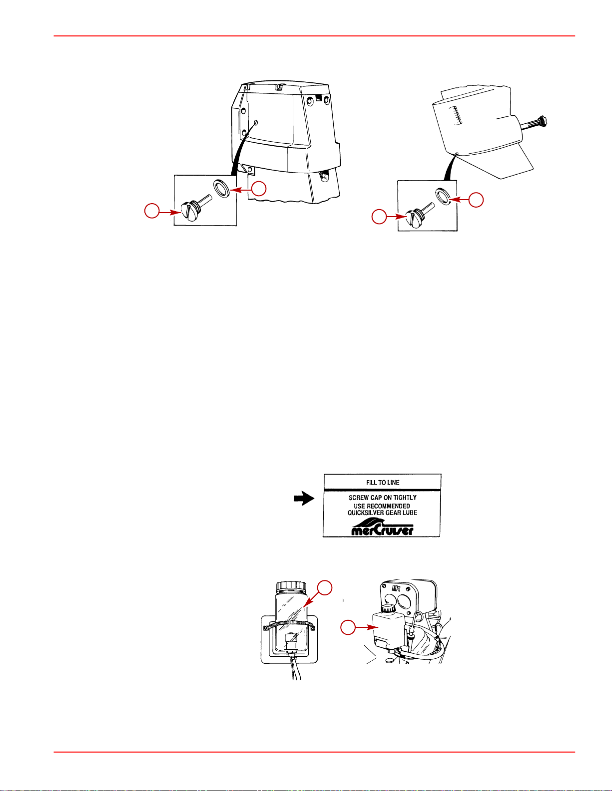
1. Fill gear lube monitor to “FULL” line on decal. Lubricate O-ring seal on gear lube monitor
neck with sterndrive oil, to ensure ease of installing and removing cap, and install gear
lube monitor cap. Do not overtighten cap - 1/4 turn, after cap contacts seal, is sufficient.
CAUTION
On models with Gear Lube Monitor, that have a dipstick in driveshaft housing cover:
DO NOT REMOVE DIPSTICK - DO NOT CHECK OIL LEVEL WITH DIPSTICK. Removal
of dipstick results in oil level raising/overfill condition, which can cause oil seal
damage; if left open, drive unit will overflow.
2. Check oil level in gear lube monitor.
Checking Lubricant for Water
Periodically inspect lubricant for water to ensure that drive unit seals are not leaking.
MODELS WITHOUT DRIVE UNIT GEAR LUBE MONITOR
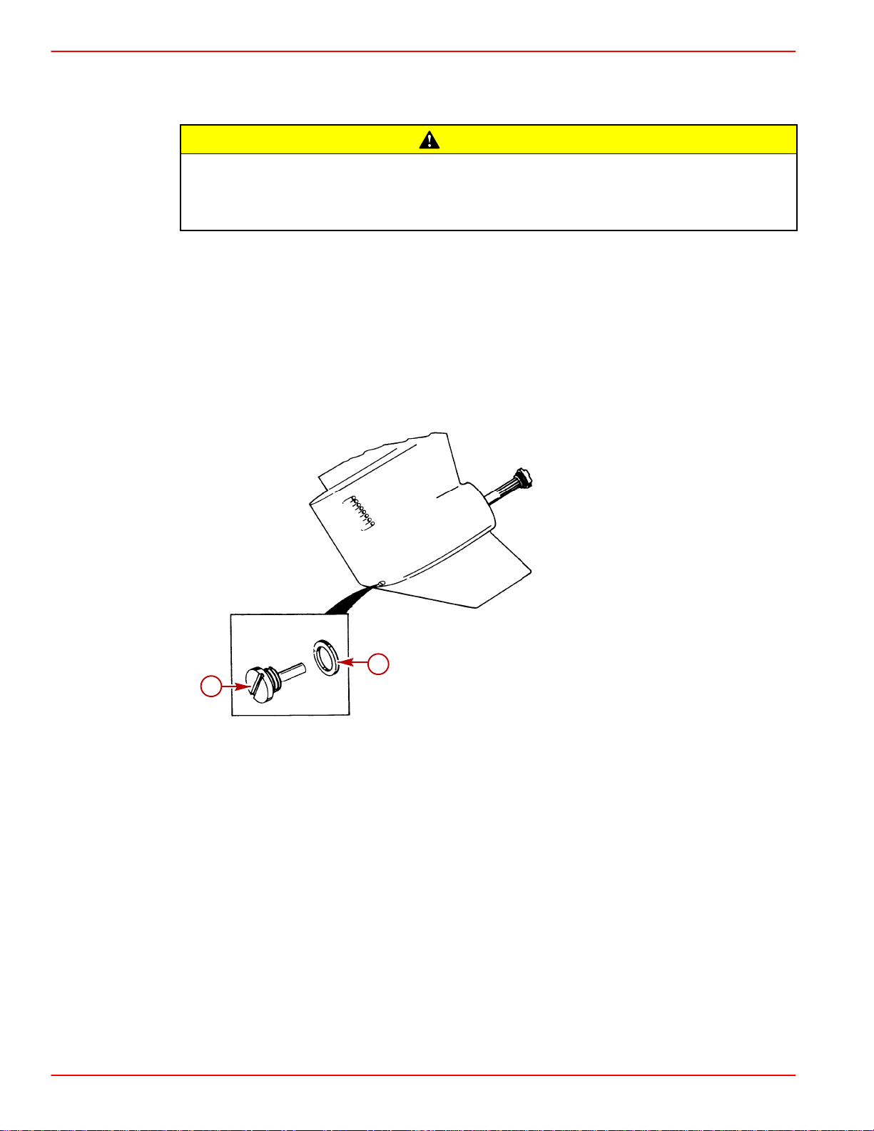
1. Trim drive unit to the full Trim UP/OUT position.
2. Remove fill/drain plug to take a sample of lubricant. If water is observed or if lubricant
appears discolored, drive unit is leaking and must be resealed.
b
a
22101
a-Fill/Drain Plug
b-Sealing Washer Or O-ring
3. Reinstall fill/drain plug. Torque to 40 lb-in. (4.0 Nm).
22103
Page 1B-10 90-818177--3 APRIL 2001
Page 23
SERVICE MANUAL NUMBER 14
MODELS WITH GEAR LUBE MONITOR
Check for water at bottom of gear lube monitor , and/or if oil appears discolored, a water leak
is indicated somewhere in the drive unit, and drive unit must be resealed.
If more than 2 fl. oz. (59ml) of Quicksilver High Performance Gear Lube is required
to fill gear lube monitor, a seal may be leaking. Find and correct cause of leak before
unit is placed in operation.
IMPORTANT: If drive unit has set overnight or longer, check for water in drive unit,
as follows:
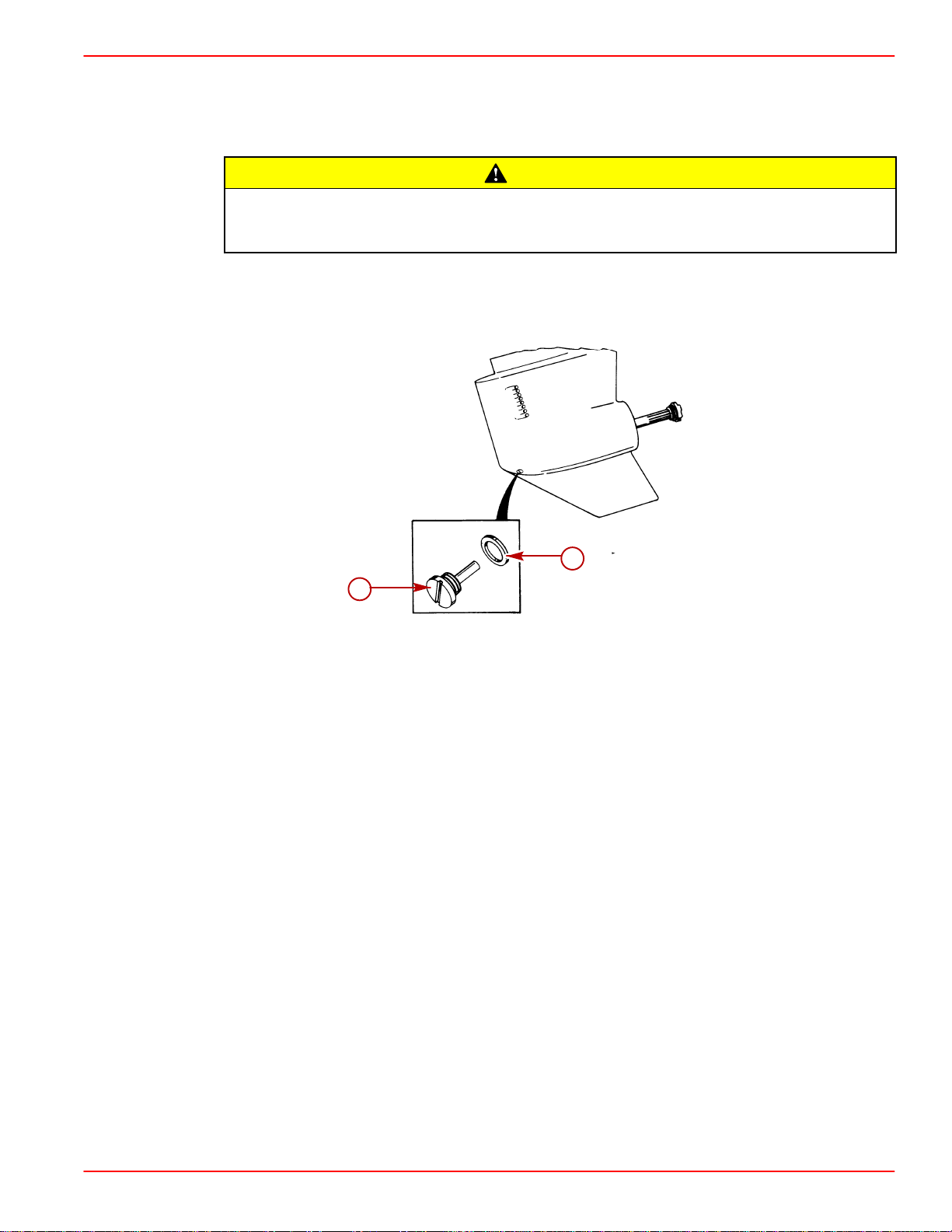
1. Trim drive unit to full Trim UP/OUT position.
MAINTENANCE
CAUTION
b
a
22101
a-Oil Fill/Drain Plug
b-Sealing Washer or O-ring
2. Remove fill/drain plug to sample lubricant. If water runs out, and/or if lubricant appears
discolored, drive unit is leaking and must be resealed.
3. Reinstall fill/drain plug. Torque to 40 lb-in. (4 Nm).
22103
90-818177--3 APRIL 2001 Page 1B-11
Page 24
MAINTENANCE SERVICE MANUAL NUMBER
Changing Lubricant
CAUTION
If any water drains from fill/drain hole, or if oil color appears discolored, a leak in
drive unit may exist. Find and correct cause of leak before placing unit back in
operatIon.
CAUTION
DO NOT attempt to fill drive unit through oil vent holes, as air will be trapped in drive
unit and unit will be damaged from lack of lubrication.
1. Trim drive unit to full Trim UP/OUT position.
b
a
a-Oil Fill/Drain Plug
b-Sealing Washer or O-ring
2. Models with drive unit Gear Lube Monitor, only: remove drive unit gear lube monitor
from bracket, remove cap, empty contents of gear lube monitor into suitable container
and discard. Clean gear lube monitor thoroughly, and return gear lube monitor to
bracket. Do not refill at this time. Check condition of hose and hose connections - replace
as necessary.
22101
22103
a
b
50028 71990
a-Round Gear Lube Monitor
b-Square Gear Lube Monitor
3. All models: remove drive unit vent plug, and fill/drain plug; allow lubricant to drain
completely.
Page 1B-12 90-818177--3 APRIL 2001
Page 25
SERVICE MANUAL NUMBER 14
4. Trim drive unit to full DOWN/IN position, with anti-ventilation plate level, to complete
draining process.
MAINTENANCE
d
b
c
a
50072
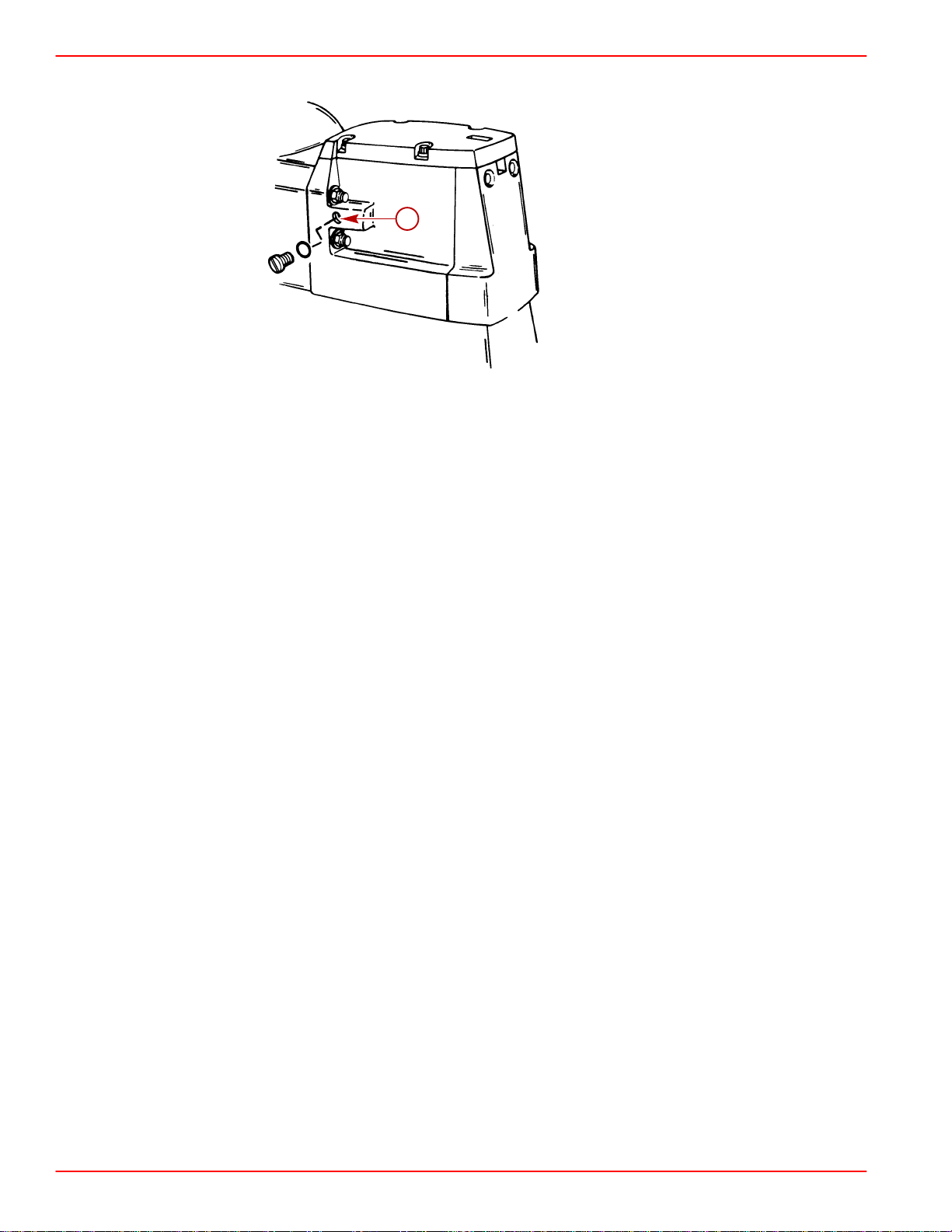
a-Oil Vent Plug
b-Sealing Washer Or O-ring
c-Vent Hole
d-Dipstick
5. Using lubricant pump, fill drive unit through fill/drain hole with lubricant until oil is even
with bottom edge of vent hole.
6. Without removing lubricant pump from fill/drain hole, reinstall oil vent plug and sealing
washer.
a. Non-Gear Lube Monitor Models: torque oil vent plug to 40 lb-in. (4 Nm).
b. Gear Lube Monitor Models: tighten oil vent plug snugly; do not torque at this time.
7. All models: remove lubricant pump and quickly reinstall fill/drain plug and sealing
washer. Torque to 40 lb-in. (4 Nm).
Models with Gear Lube Monitor:
8. Remove oil vent plug and sealing washer (with drive unit in full DOWN/IN position).
9. Fill gear lube monitor bottle with Quicksilver High-Performance Gear Lube. When oil
starts to run out the vent hole (gear lube hose between drive unit and gear lube bottle
becomes filled), reinsert vent plug. Torque to 40 lb-in. (4 Nm).
10. Fill gear lube monitor to “FULL” line on decal. Lubricate O-ring seal on gear lube monitor
neck with sterndrive oil, to ensure ease of installing and removing cap. Install gear lube
monitor cap. Do not overtighten.
90-818177--3 APRIL 2001 Page 1B-13
Page 26
MAINTENANCE SERVICE MANUAL NUMBER
11. All models: recheck oil level after first use.
a
50072
a-Vent Hole
General Maintenance
Maintaining Power Package Exterior Surfaces
Entire Power Package should be sprayed at recommended intervals with Quicksilver
Corrosion Guard. Follow instructions on can for proper application.
At least once each year, entire Power Package should be cleaned and external surfaces that
have become bare should be repainted with Quicksilver Primer and Spray Paint.
Steering Head and Remote Control Maintenance
Lubricate steering head and remote control with 2-4-C Marine Lubricant with Teflon. Inspect
steering head and remote control for ease of operation.
Checking Quicksilver MerCathode System
If boat is equipped with a Quicksilver MerCathode System, system should be tested to
ensure that it is providing adequate output to protect underwater metal parts on boat. Test
should be made where boat is moored, using Quicksilver Reference Electrode and Test
Meter.Refer to section 7.
Maintaining Anodic Trim Tab or Plate
Each sterndrive unit is equipped with a sacrificial anodic trim tab (or plate on later models)
to help protect underwater metal parts from galvanic corrosion. Because of its
self-sacrificing nature, trim tab (or plate) MUST BE replaced if eroded 50% or more. An
anodic plate is the new service replacement for the anodic trim tab. Install the anodic plate
in place of the anodic trim tab. Refer to Section 7.
Checking Optional Quicksilver Anti-Corrosion Anode Kit
If boat is equipped with Quicksilver Anti-Corrosion Anode Kit, inspect anode and replace if
eroded to less than 50% of its original size. Carefully follow installation instructions, that
accompany new Anode Kit, to ensure proper installation.
Page 1B-14 90-818177--3 APRIL 2001
Page 27
SERVICE MANUAL NUMBER 14
Boat Bottom Care
To achieve maximum performance and fuel economy, boat bottom MUST BE kept clean.
Accumulation of marine growth or other foreign matter can greatly reduce boat speed and
increase fuel consumption. To ensure best performance and efficiency, periodically clean
boat bottom in accordance with manufacturer’s recommendations.
In some areas, it may be advisable to paint the bottom to help prevent marine growth. Refer
to the following information for special notes about the use of antifouling paints.
Antifouling Paint
IMPORTANT: Corrosion damage that results from the improper application of
antifouling paint will not be covered by the limited warranty.
Painting Boat Hull or Boat T ransom: Antifouling paint may be applied to boat hull and boat
transom but you must observe the following precautions:
IMPORTANT: DO NOT paint anodes or MerCathode System reference electrode and
anode, as this will render them ineffective as galvanic corrosion inhibitors.
MAINTENANCE
IMPORTANT: If antifouling protection is required for boat hull or boat transom
copper or tin base paints, if not prohibited by law, can be used. If using copper or tin
based antifouling paints, observe the following:
• Avoid an electrical interconnection between the Mercury MerCruiser Product,
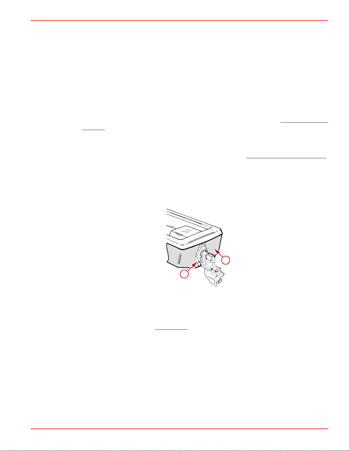
Anodic Blocks, or MerCathode System and the paint by allowing a minimum of 1-1/2
in. (40mm) UNPAINTED area on transom of the boat around these items.
a
b
71176
a-Painted Boat Transom
b-Minimum 1-1/2 in. (40 mm) UNPAINTED Area Around Transom Assembly
NOTE: Drive unit and transom assembly can be painted with a good quality marine paint
or an antifouling paint that DOES NOT contain copper, tin, or any other material that could
conduct electrical current. Do not paint drain holes, anodes, MerCathode system, and items
specified by boat manufacturer.
,
Maintaining Ground Circuit Continuity
The transom assembly and sterndrive unit are equipped with a ground wire circuit, to ensure
good electrical continuity between engine, transom assembly and sterndrive components.
Good continuity is essential for the MerCathode System to function effectively. Refer to
Section 7.
90-818177--3 APRIL 2001 Page 1B-15
Page 28

MAINTENANCE SERVICE MANUAL NUMBER
Power Package Layup (Out of Season Storage)
Engine
Refer to appropriate Engine Service Manual.
Sterndrive
1. Lubricate steering system. Refer to Section 6.
2. Lubricate transom gimbal housing assembly swivel shaft, gimbal bearing, and propeller
shaft. Refer to Section 4 and Section 1-B.
3. Lubricate sterndrive unit U-joint shaft splines and cross bearings. Refer to Section 3-A.
4. Inspect U-joint bellows for cracks or other signs of deterioration. Check bellows clamps
for tightness. Refer to Section 4.
5. Check engine alignment. Refer to Engine Service Manual.
6. Change sterndrive unit oil. Refer to Section 1-B.
Page 1B-16 90-818177--3 APRIL 2001
Page 29
SERVICE MANUAL NUMBER 14
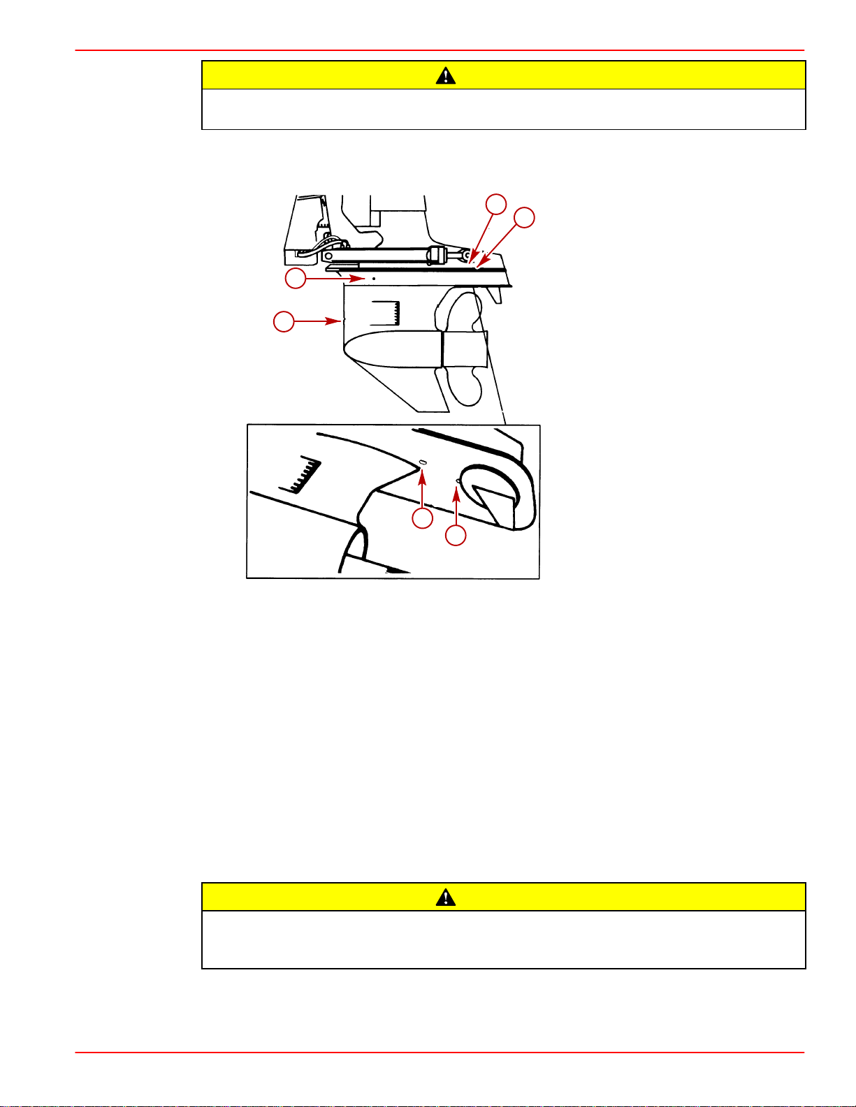
Water holes in sterndrive unit MUST BE open to allow water to drain, or trapped water may freeze and cause severe damage to housings.
7. Using a piece of wire, check water drain holes in sterndrive unit to ensure that they are
open.
MAINTENANCE
CAUTION
e
b
d
a
71216
f
c
70134
Sterndrive Unit Water Drain Holes
a-Speedometer Pitot Tube
b-Trim Tab Cavity Vent Hole
c-Trim Tab Cavity Drain Passage
d-Gear Housing Water Drain Hole (One Each - Port and
Starboard)
e-Gear Housing Cavity Vent Hole
f-Gear Housing Cavity Drain Hole
8. Inspect sterndrive for damage. Repair or replace damaged components.
9. Clean sterndrive exterior surfaces and repaint any bare metal surfaces with Quicksilver
Primer and Spray Paint. Refer to Section 1-B.
10. After paint has dried spray entire sterndrive with Quicksilver Corrosion Guard. Refer to
Section 1-B.
CAUTION
Store sterndrive unit in the full trim DOWN/IN position. U-joint bellows may develop
a “set” if unit is stored in raised position and may fail when unit is returned to service.
11. Place sterndrive unit in the full trim DOWN/IN position.
12. Store battery. Refer to battery manufacturer’s instructions.
90-818177--3 APRIL 2001 Page 1B-17
Page 30

MAINTENANCE SERVICE MANUAL NUMBER
Power Package Recommissioning
Engine
Refer to appropriate Engine Service Manual.
Sterndrive
1. Perform ALL maintenance specified for completion “At Least Once Each Year” in
“Maintenance Chart” (Refer to Section 1-B), except items which were performed at the
time of sterndrive layup.
2. Install fully-charged battery. Clean battery cable clamps and terminals and reconnect
cables. Be sure to tighten clamps securely. Apply a thin coat of petroleum based grease
to clamps and terminals to help retard corrosion.
3. After recommissioning and starting engine, check steering system and shift control for
proper operation.
Page 1B-18 90-818177--3 APRIL 2001
Page 31

SERVICE MANUAL NUMBER 14
MAINTENANCE
THIS PAGE IS INTENTIONALLY BLANK
90-818177--3 APRIL 2001 Page 1B-19
Page 32

MAINTENANCE SERVICE MANUAL NUMBER
THIS PAGE IS INTENTIONALLY BLANK
Page 1B-20 90-818177--3 APRIL 2001
Page 33

SERVICE MANUAL NUMBER 14
TROUBLESHOOTING
IMPORTANT INFORMATION
Section 1C - Troubleshooting
Table of Contents
Troubleshooting 1C-3. . . . . . . . . . . . . . . . . . . . .
Sterndrive Unit Troubleshooting 1C-3. . . . . . .
Sterndrive Unit Will Not Slide Into
Bell Housing 1C-3. . . . . . . . . . . . . . . . . . . . .
Drive Unit Does Not Shift Into Gear;
Remote Control Shift Handle Moves 1C-3
Drive Unit Does Not Shift Into Gear;
Remote Control Shift Handle Does
Not Move 1C-3. . . . . . . . . . . . . . . . . . . . . . .
Drive Unit Shifts Hard 1C-4. . . . . . . . . . . . .
Drive Unit In Gear, Will Not Shift Out
Of Gear 1C-4. . . . . . . . . . . . . . . . . . . . . . . . .
Gear Housing Noise 1C-4. . . . . . . . . . . . . .
Drive Shaft Housing Noise 1C-5. . . . . . . . .
Drive Shaft Housing Noise
(Continued) 1C-6. . . . . . . . . . . . . . . . . . . . .
Drive Shaft Housing Noise
(Continued) 1C-7. . . . . . . . . . . . . . . . . . . . .
Performance Troubleshooting 1C-8. . . . . . . . .
Low WOT Engine Rpm 1C-8. . . . . . . . . . . .
High WOT Engine Rpm 1C-8. . . . . . . . . . . .
Propeller Ventilating/Cavitating 1C-8. . . . .
Poor Boat Performance And/Or
Poor Maneuverability-Bow Too Low 1C-8.
Poor Boat Performance And/Or
Poor Maneuverability-Bow Too High 1C-9
Power Steering 1C-9. . . . . . . . . . . . . . . . . . . . .
Hard Steering - Helm And Cable 1C-9. . . .
Hard Steering (Engine Running)
- Power Steering System 1C-10. . . . . . . . . .
Power Steering System External
Fluid Leaks 1C-10. . . . . . . . . . . . . . . . . . . . . .
Compact Hydraulic Steering 1C-11. . . . . . . . . .
Important Information 1C-11. . . . . . . . . . . . .
Helm Becomes Jammed
During Filling 1C-11. . . . . . . . . . . . . . . . . . . .
System Difficult To Fill 1C-11. . . . . . . . . . . . .
Steering Hard To Turn 1C-11. . . . . . . . . . . . .
Helm Unit Bumpy - Requires
Too Many Turns 1C-11. . . . . . . . . . . . . . . . . .
Power Trim Electrical System 1C-12. . . . . . . . .
Power Trim Pump Motor Will Not Run
In The OUT/UP Or IN/DOWN
Direction 1C-12. . . . . . . . . . . . . . . . . . . . . . . .
Power Trim Pump Motor Will Not Run
In The OUT/UP Or IN/DOWN
Direction 1C-13. . . . . . . . . . . . . . . . . . . . . . . .
Power Trim Pump Motor Runs In
The OUT/UP Direction, But Not In
The IN/DOWN Direction 1C-13. . . . . . . . . . .
Power Trim Pump Motor Runs In
The OUT/UP Direction, But Not In
The IN/DOWN Direction 1C-14. . . . . . . . . . .
1
C
Power Trim Pump Motor Runs In
The IN/DOWN Direction, But Not
In The OUT/UP Direction-Both
Trim And Trailer Switches
Inoperative- 1C-14. . . . . . . . . . . . . . . . . . . . .
Power Trim Pump Motor Runs In
The IN/DOWN Direction, But Not
In The OUT/UP Direction-Both
Trim And Trailer Switches
Inoperative 1C-14. . . . . . . . . . . . . . . . . . . . . .
Trim Control OUT/UP Trim Switch
Inoperative 1C-15. . . . . . . . . . . . . . . . . . . . . .
Trim Control Trailer Switch
Inoperative 1C-15. . . . . . . . . . . . . . . . . . . . . .
Trim System Functions While
Unattended 1C-15. . . . . . . . . . . . . . . . . . . . . .
Power Trim System Wiring Diagram 1C-16. . .
Power Trim Hydraulic System 1C-17. . . . . . . . .
Drive Unit Cannot Be Trimmed
OUT/UP Or Trims Slowly Or
With Jerky Movements 1C-17. . . . . . . . . . . .
Drive Unit Will Not Stay In Trimmed
OUT/UP Position 1C-17. . . . . . . . . . . . . . . . .
Sterndrive Unit Trails OUT/UP On
Deceleration Or When Shifting Into
Reverse 1C-17. . . . . . . . . . . . . . . . . . . . . . . .
Oil Foams Out Of Pump Fill/Vent
Screw 1C-18. . . . . . . . . . . . . . . . . . . . . . . . . .
Sterndrive Unit Cannot Be
Lowered From UP Position Or
Lowers With Jerky Movements 1C-18. . . . .
Sterndrive Unit Will Not Stay In
Full UP Position For Extended
Periods 1C-18. . . . . . . . . . . . . . . . . . . . . . . . .
Sterndrive Will Not Stay In The
Trimmed OUT/UP Position When
Underway 1C-19. . . . . . . . . . . . . . . . . . . . . . .
Sterndrive Unit Trails OUT/UP
On Deceleration Or When Shifting
Into Reverse 1C-19. . . . . . . . . . . . . . . . . . . .
Oil Foams Out Of Pump Fill/Vent
Screw 1C-19. . . . . . . . . . . . . . . . . . . . . . . . . .
Trim Motor Runs But Does Not
Pump Oil 1C-19. . . . . . . . . . . . . . . . . . . . . . . .
Trim Pump Runs Slowly In Both
Directions 1C-19. . . . . . . . . . . . . . . . . . . . . . .
Trim Pump Runs Slowly With A
Laboring Sound 1C-19. . . . . . . . . . . . . . . . . .
90-818177--3 APRIL 2001 Page 1C-1
Page 34

TROUBLESHOOTING SERVICE MANUAL NUMBER 14
Table of Contents (continued)
Power Trim Hydraulic Schematic 1C-20. . . . . .
Auto Trim II Electrical System 1C-21. . . . . . . . .
Pump Motor Will Not Run UP Or
DOWN In Either Manual Or Auto
Mode 1C-21. . . . . . . . . . . . . . . . . . . . . . . . . . .
Pump Motor Will Not Stop Running
Down In Auto Mode 1C-22. . . . . . . . . . . . . .
Pump Motor Will Not Run Up Or
Down In Auto Mode 1C-22. . . . . . . . . . . . . .
Trim System Completely Inoperative
In Manual Mode 1C-23. . . . . . . . . . . . . . . . .
Pump Motor Will Run UP, But Not
Down In Both Manual And Auto
Modes 1C-23. . . . . . . . . . . . . . . . . . . . . . . . . .
Pump Motor Runs Down, But Not
UP In Both The Manual And Auto
Modes 1C-23. . . . . . . . . . . . . . . . . . . . . . . . . .
Pump Motor Will Run Down, But
Not UP In Auto Mode 1C-24. . . . . . . . . . . . .
Pump Motor Will Run UP, But Not
DOWN In Auto Mode 1C-24. . . . . . . . . . . . .
Trim DOWN/IN Switch Inoperative
In Manual Trim Control 1C-24. . . . . . . . . . . .
Trim UP/OUT Switch Inoperative
In Manual Trim Control 1C-25. . . . . . . . . . . .
Trailer Switch In Manual, Trim
Control Inoperative 1C-25. . . . . . . . . . . . . . .
Boat Is On Plane Well Before
Drive Unit Begins To Trim Out 1C-25. . . . .
Boat Is Not On Plane Before
Drive Unit Begins To Trim Out 1C-25. . . . .
Auto Trim II System Wiring Diagram 1C-26. . .
Corrosion Protection 1C-26. . . . . . . . . . . . . . . . .
Corrosion On Underwater Parts,
Without MerCathode Or Impressed Current
Protection 1C-27. . . . . . . . . . . . . . . . . . . . . . .
Corrosion On Underwater Parts,
With MerCathode Or Impressed
Current Protection 1C-28. . . . . . . . . . . . . . . .
Corrosion On Underwater Parts,
With MerCathode Or Impressed
Current Protection 1C-30. . . . . . . . . . . . . . . .
Testing Procedure for Corrosion
Protection 1C-31. . . . . . . . . . . . . . . . . . . . . . .
MerCathode Controller 1C-32. . . . . . . . . . . .
Shift System Troubleshooting 1C-33. . . . . . . . .
Troubleshooting Shift Problems 1C-34. . . . .
Checking for Excessive Play 1C-36. . . . . . .
Isolating Excessive Play 1C-40. . . . . . . . . . .
Checking Remote Control Shift
Cable Output 1C-42. . . . . . . . . . . . . . . . . . . .
Checking Cutout Switch Timing
(Models With Roller Type Switch) 1C-43. .
Checking Cutout Switch Timing
(Models With Plunger Type Switch) 1C-45.
Checking Operation 1C-47. . . . . . . . . . . . . . .
Page 1C-2 90-818177--3 APRIL 2001
Page 35

SERVICE MANUAL NUMBER 14
Troubleshooting
This section is a guide for performance and product troubleshooting. Referrals to specific
sections of this manual are made where special tests or repair procedures are to be
performed.
Because of the relationship between Power Package components (engine and sterndrive),
it will be necessary in some cases to simultaneously refer to the appropriate Engine Service
Manual for further troubleshooting information.
Effective troubleshooting is best enhanced by:
• Personal product knowledge and experience of the trained mechanic/technician.
• Allowing adequate time for testing and analysis.
• Utilizing these charts as a “guide” - a starting point.
Sterndrive Unit Troubleshooting
Sterndrive Unit Will Not Slide Into Bell Housing
Cause Special Instructions
TROUBLESHOOTING
U-joint shaft splines not aligned with
engine coupler splines.
Engine not aligned. Check engine alignment.
Gimbal bearing not properly installed.
Damaged U-joint shaft splines and/or
engine coupler splines.
Rotate propeller shaft
COUNTERCLOCKWISE to align splines.
Check engine alignment to determine if
gimbal bearing is cocked or improperly
installed in gimbal housing.
Inspect and replace if necessary.
Drive Unit Does Not Shift Into Gear; Remote Control Shift Handle Moves
NOTE:For additional information on troubleshooting, refer to SECTION 2A and see
“Troubleshooting Shift Problems.”
Cause Special Instructions
Shift cables improperly adjusted. Adjust shift cables.
Shift cables not connected. Install and adjust shift cables.
Inner core wire broken or loose. Reconnect or replace inner core wire.
Drive Unit Does Not Shift Into Gear; Remote Control Shift Handle Does Not
Move
NOTE:For additional information on troubleshooting, refer to SECTION 2A and see
“Troubleshooting Shift Problems.”
Cause Special Instructions
Control box not properly assembled. Properly reassemble control box.
Broken or damaged linkage in control box. Repair linkage.
Controls improperly adjusted-cable end
guide hitting brass barrel.
90-818177--3 APRIL 2001 Page 1C-3
Adjust shift cables.
Page 36

TROUBLESHOOTING SERVICE MANUAL NUMBER 14
Drive Unit Shifts Hard
NOTE:For additional information on troubleshooting, refer to SECTION 2A and see
“Troubleshooting Shift Problems.”
Cause Special Instructions
Shift cables improperly adjusted. Adjust shift cables.
Damaged remote control or drive unit shift
cable.
Shift cable too short (sharp bends) or too
long (loops and long bends).
Corroded shift cables.
Internal wear in remote control box. Repair as needed.
Shift cable attaching nuts too tight (end
cannot pivot).
Shift cable pivot ends are corroded or not
lubricated.
Drive Unit In Gear, Will Not Shift Out Of Gear
NOTE:For additional information on troubleshooting, refer to SECTION 2A and see
“Troubleshooting Shift Problems.”
Cause
Shift cable broken. Replace cable and adjust.
Cable end not connected in drive unit. Remove and reinstall drive unit.
Remote control damaged. Repair or replace remote control.
Replace cable(s) and adjust.
Select and install proper length cable.
Replace, adjust and check for water
leakage.
Properly install nuts.
Clean and lubricate.
Special Instructions
Internal shift mechanism damage. Repair or replace as necessary.
Gear Housing Noise
Metal particles in drive unit lubricant.
Propeller incorrectly installed.
Propeller shaft bent.
Incorrect gear shimming.
Worn or damaged gears and/or bearings
caused by impact, overheating or
improper shimming.
Cause Special Instructions
Disassemble, clean and inspect and
replace necessary components. (Refer to
SECTION 3B, 3C or 3D)
Inspect mounting hardware. Install
propeller correctly.
Inspect and replace if necessary. (Refer to
SECTION 3B, 3C or 3D)
Check gear housing backlash and pinion
gear height. (Refer to SECTION 3B, 3C or
3D)
Disassemble, inspect and replace. (Refer
to SECTION 3B, 3C or 3D)
Page 1C-4 90-818177--3 APRIL 2001
Page 37

SERVICE MANUAL NUMBER 14
Drive Shaft Housing Noise
TROUBLESHOOTING
Cause Special Instructions
Engine flywheel housing contacting inner
transom plate or exhaust pipe.
Propeller with untrue or out-of-balance
blades.
Abnormal sterndrive operation.
U-joint cross and bearing assembly
retaining rings improperly installed or of
incorrect size.
Excessive side-to-side play in U-joint
cross and bearing assemblies.
U-joint bearing caps contacting U-joint
bellows retention sleeve.
U-joint cross and bearings rough.
O-rings missing or flattened out on U-joint
shaft causing shaft to rattle against ID of
gimbal bearing.
Determine cause for interference (loose
engine mounts, transom too thin, etc.) and
correct as necessary.
Repair or replace, as required.
Instruct operator on proper operating
technique.
Make sure that proper thickness retaining
rings are used and that rings are fully
seated in U-joint bearing cap grooves.
(Refer to SECTION 3A)
Replace cross and bearing assembly.
Make sure proper cross and bearing
assemblies are used. If interference is
severe, replace cross and bearing
assembly and / or sleeve assembly.
Replace assemblies. Signs of scoring,
galling or roughness are the result of lack
of lubricant. (Refer to SECTION 3A)
Install new O-rings. (Refer to SECTION
3A)
90-818177--3 APRIL 2001 Page 1C-5
Page 38

TROUBLESHOOTING SERVICE MANUAL NUMBER 14
Drive Shaft Housing Noise (Continued)
Cause Special Instructions
Remove U-joint coupling end yoke and
insert into gimbal bearing and engine
Worn U-joint shaft splines and/or engine
coupler splines.
Engine alignment incorrect or engine
coupler crooked.
Gimbal bearing rough.
Loose gimbal bearing.
Gimbal bearing not fully seated in gimbal
housing.
Excessive clearance between gimbal ring
and gimbal housing. This could cause
misalignment between bell housing and
gimbal housing and also may allow gimbal
ring to vibrate up and down.
Improperly installed or failed rear engine
mounts. This will affect engine alignment,
but usually is not detectable with engine
alignment tool.
coupling. Rotate shaft back and forth. If
play is excessive, replace U-joint coupling
end yoke and/or engine coupler, as
necessary.
Adjust alignment. Ensure that alignment
tool moves in and out of coupler freely.
After proper alignment has been obtained,
check for a crooked coupler by rotating
engine coupler 1/2 turn and rechecking
alignment. If proper alignment is no longer
observed, coupler is crooked and must be
replaced. (Refer to SECTION 2)
Replace gimbal bearing. (Refer to
SECTION 4)
IMPORTANT: Gimbal bearing and carrier
MUST BE replaced as an assembly be-
cause they are a matched set. Failure to
do this may result in a loose bearing fit in
carrier.
Reinstall bearing assembly using a new
tolerance ring if carrier is loose in gimbal
housing. If bearing is loose in carrier,
bearing assembly must be replaced.
(Refer to SECTION 4)
Drive bearing assembly into place.
Check and adjust clearance. (Refer to
SECTION 4)
Check for uneven mount height, or loose
or soft mounts. Make sure there is
clearance between flywheel housing and
fiber washer. If no clearance exists,
mounts have probably sagged. Install
mounts correctly or replace, as necessary.
Page 1C-6 90-818177--3 APRIL 2001
Page 39

SERVICE MANUAL NUMBER 14
Drive Shaft Housing Noise (Continued)
Cause Special Instructions
Boat transom too thin. Thickness: 2 in.
(51 mm) minimum, 2-1/4 in. (57 mm)
maximum.
Boat transom thickness uneven. This could
affect engine to transom assembly
alignment and is usually not detectable with
alignment tool. Variation: 1/8 in. (3 mm)
maximum.
Bell housing contacting gimbal ring. This
would cause knocking in the fully trimmed
IN position only.
Stringer height uneven or transom
assembly installed cocked on boat
transom. This will affect engine alignment,
but is usually not detectable with
alignment tool.
TROUBLESHOOTING
Add thickness to transom.
Repair boat as necessary.
Check for soft or split trim cylinder
bushings and loose or worn hinge pin
bushings. (Refer to SECTION 5B)
Measure the distance between the engine
flywheel housing and the inner transom
plate on both sides. If distances are
uneven, the problem may be due to
uneven stringer height or a cocked
transom assembly. Adjust the stringer
height or relocate the transom cutout as
required.
Weak boat transom or boat bottom that
flexes under power and causes engine
misalignment - this condition will usually
cause engine coupler failure.
Rear engine mount attaching hardware
improperly installed or missing.
Engine mounting holes drilled off-center in
inner transom plate engine supports or
engine flywheel housing
Misalignment between bell housing,
gimbal housing and engine coupler.
This condition can sometimes be detected
by having someone apply force to the top
of the drive unit while watching the inner
transom plate. If movement can be
observed, the transom is weak and must
be repaired.
Reinstall hardware correctly.
Make sure the holes are equally spaced
fore and aft and are equal distance from
the centerline.
Contact your service center and arrange
to have a technical service representative
check the unit using a special gauge.
90-818177--3 APRIL 2001 Page 1C-7
Page 40

TROUBLESHOOTING SERVICE MANUAL NUMBER 14
Performance Troubleshooting
Low WOT Engine Rpm
Cause Special Instructions
Improper drive unit trim angle. Properly adjust drive unit trim angle.
Damaged propeller. Repair or replace.
Improper propeller pitch.
Dirty or damaged boat bottom. Clean and/or resurface boat bottom.
Drive installation too low on transom.
Permanent “hook” in boat bottom (some
boats are built with a slight “hook” for
correct boat performance).
“Power hook” or weak boat bottom.
High WOT Engine Rpm
Propeller ventilating. Determine cause for ventilation.
Improper propeller pitch.
Propeller hub slipping. Replace hub or replace propeller.
Water test boat using a lower pitch
propeller.
Contact boat manufacturer for installation
specifications.
Check for a hook in the boat bottom by
placing a straight edge, at least 6 ft. (2 m)
long, under the bottom edge of the
transom. If a hook is found, contact the
boat manufacturer.
Water test boat. Boat will perform normally
until hook develops at high speed, then
loss of rpm and speed will occur. Contact
boat manufacturer.
Cause Special Instructions
Water test boat using a higher pitch
propeller.
Drive installation too high on transom.
Engine coupler hub spun. Replace coupler.
Contact boat manufacturer for installation
specifications.
Propeller Ventilating/Cavitating
Cause Special Instructions
Drive unit trimmed too high. Trim drive unit IN/DOWN.
Incorrect propeller. Install correct propeller.
Poor Boat Performance And/Or Poor Maneuverability-Bow Too Low
Cause Special Instructions
Improper drive unit trim angle. Properly adjust drive unit trim angle.
Redistribute boat load to stern. If bow
Boat is bow heavy.
Boat is underpowered.
overweight is caused by permanently
installed fuel tank(s), contact the boat
manufacturer.
Check horsepower to weight ratio. Contact
the boat manufacturer.
Page 1C-8 90-818177--3 APRIL 2001
Page 41

SERVICE MANUAL NUMBER 14
Permanent hook in boat bottom (some
boats are built with a slight hook for
correct boat performance).
Power hook or weak boat bottom.
Check for a hook in the boat bottom by
placing a straight edge, at least 6 ft. (2 m)
long, under the bottom edge of the
transom. If a hook is found, contact the
boat manufacturer.
Water test boat. Boat will perform normally
until hook develops at high speed, then
loss of rpm and speed will occur. Contact
boat manufacturer.
TROUBLESHOOTING
Poor Boat Performance And/Or Poor Maneuverability-Bow Too High
Cause Special Instructions
Improper drive unit trim angle. Properly adjust drive unit trim angle.
Redistribute boat load to bow. If stern
Boat is stern heavy.
Propeller pitch too high.
Permanent rocker in boat bottom (some
boats are built with a slight rocker for
correct boat performance).
Power hook or weak boat bottom.
overweight is caused by permanently
installed fuel tank(s), contact the boat
manufacturer.
Water test the boat using a lower pitch
propeller.
Check for a rocker in the boat bottom by
placing a straight edge, at least 6 ft. (2 m)
long, under bottom edge of the transom. If
a rocker is found, contact the boat
manufacturer.
Water test boat. Boat will perform normally
until hook develops at high speed, then
loss of rpm and speed will occur. Contact
boat manufacturer.
Power Steering
If Power Package is equipped with Power Steering, first determine if problem is caused by
the Power Steering System or the Ride Guide portion of the Steering System.
1. Remove clevis pin which attaches steering cable to power steering unit piston rod end
clevis. Remove clevis pin which secures piston rod end clevis to sterndrive steering
lever.
2. Turn steering wheel through entire steering range. If steering difficulty is encountered,
it is located in the Ride Guide Steering System. If steering wheel turns with ease,
problem is located in Power Steering System.
Hard Steering - Helm And Cable
Cause Special Instructions
Damaged steering cable. Replace cable. (Refer to SECTION 2)
Steering cable too short (sharp bends) or
too long (loops and long bends).
Steering cable corroded or not lubricated. Lubricate or replace the cable.
Over-lubed cable. Replace cable.
RideGuide rack or rotary head not
lubricated.
Select and install proper length cable.
(Refer to SECTION 2A)
Disassemble and lubricate.
90-818177--3 APRIL 2001 Page 1C-9
Page 42

TROUBLESHOOTING SERVICE MANUAL NUMBER 14
Hard Steering (Engine Running) - Power Steering System
Cause Special Instructions
Low power steering pump fluid level. Check fluid level. (Refer to SECTION 6A)
Loose power steering pump drive belt.
Air in system.
Fluid leak.
If the above 4 steps do not solve the
problem, test the power steering system.
Power Steering System External Fluid Leaks
Cause Special Instructions
Pump reservoir leaking at fill cap
(reservoir too full).
Pump reservoir leaking at fill cap (air or
water in fluid).
Loose hose connections. Tighten hose connections.
Damaged hose. Replace hose.
Bad cylinder piston rod seal. Replace cylinder.
Adjust belt tension. (Refer to SECTION
6A)
Cycle to remove air. (Refer to SECTION
6A)
Locate and correct source of leak.
(Refer to SECTION 6A)
Test power steering system. (Refer to
SECTION 6A)
Remove fluid to bring to proper level.
Locate source of air or water and correct.
Air may enter because of low reservoir
fluid level or internal pump leak. Test
pump. (Refer to SECTION 6A)
Damaged or worn control valve seals. Replace cylinder.
Bad power steering pump seals and
O-rings.
Cracked or porous metal parts. Replace part(s).
Repair pump. (Refer to SECTION 6A)
Page 1C-10 90-818177--3 APRIL 2001
Page 43

SERVICE MANUAL NUMBER 14
Compact Hydraulic Steering
Important Information
Whenever a troubleshooting solution calls for removal from vessel and/or dismantling of
steering system components, such work must be carried out by a qualified marine
mechanic. The following is offered as a guide only and neither Mercury MerCruiser nor the
helm manufacturer are responsible for any consequences resulting from incorrect repairs.
Most faults occur when the installation instructions are not followed and usually show up
immediately upon filling the system. The most common faults encountered and their likely
cause and solution are provided in the following.
Sometimes when returning the steering wheel from a locked position, a slight resistance
may be felt and a clicking noise may be heard. This should not be mistaken as a fault, as
it is a completely normal situation caused by the releasing of the lockspool in the system.
Avoid serious injury or death due to FIRE or EXPLOSION. Be sure that engine compartment is well ventilated and that no gasoline vapors are present to prevent the
possibility of a FIRE or EXPLOSION.
Helm Becomes Jammed During Filling
TROUBLESHOOTING
WARNING
Blockage in the line between the helm(s)
and the cylinder(s).
System Difficult To Fill
Air in system. Review filling instructions.
Steering Hard To Turn
Steering cylinder pivot bushings are too
tight or trunion is bent, causing
mechanical binding.
Restrictions in hoses. Find restrictions and correct.
Air in hydraulic fluid. See filling and purging instructions.
Cause Special Instructions
Make certain that hoses were not kinked
or pinched during installation. If so, the
hose must be removed and replaced.
Cause Special Instructions
Cause Special Instructions
To test, disconnect clevis from steering
lever and turn the steering wheel. If it now
turns easy, correct cause of mechanical
binding. Please note that excessively
loose connections to steering cylinder or
steering lever can also cause mechanical
binding.
Wrong hydraulic fluid has been used to fill
steering system.
Drain system and fill with approved
hydraulic fluid.
Helm Unit Bumpy - Requires Too Many Turns
Cause Special Instructions
Dirt in inlet check of helm pump. Replace helm unit.
90-818177--3 APRIL 2001 Page 1C-11
Page 44

TROUBLESHOOTING SERVICE MANUAL NUMBER 14
Power Trim Electrical System
NOTE:Refer to “Power Trim System Wiring Diagram.”
Power Trim Pump Motor Will Not Run In The OUT/UP Or IN/DOWN Direction
SOLENOIDS DO NOT CLICK
Cause Special Instructions
Bad electrical connection at the 110 amp
fuse or at the battery or the harness came
unplugged from the pump
20 amp fuse blown.
Power trim pump battery cables or wiring
harness connections corroded or loose.
Trim control wiring harness connector
loose or corroded.
110 amp fuse blown (does not apply to
intermittent problem).
Open circuit in trim control wiring
harness.
Thermal circuit breaker in pump motor
open.
Check all electrical connection points
Determine cause for the blown fuse and
correct before replacing fuse.
NOTE:If fuse blows while trimming OUT/UP
or raising drive unit, problem may be due to
grounded trim limit switch leads. To check
for grounded condition, disconnect trim limit
switch leads at bullet connector 14, 15, 16
and 17. If drive unit can now be raised (using
“Trailer” switch), trim limit switch or leads are
grounded.
Clean and/or tighten connections 1, 2, 4,
10, 11, 12 and 18 as necessary.
Clean and secure connection 13 as
necessary.
Check for voltage at terminal 4. If no
voltage indicated, determine cause of
blown fuse.
Check for battery voltage at terminal 8
while trimming OUT/UP and at terminal 6
while trimming OUT/UP. If no voltage is
indicated, check trim control for a loose or
corroded connection or a damaged power
supply lead in harness.
Replace commutator end plate assembly.
Page 1C-12 90-818177--3 APRIL 2001
Page 45

SERVICE MANUAL NUMBER 14
TROUBLESHOOTING
Power Trim Pump Motor Will Not Run In The OUT/UP Or IN/DOWN Direction
BOTH SOLENOIDS CLICK
Cause Special Instructions
Check for battery voltage at terminals 5
Faulty solenoids or loose or corroded
connections.
Pump motor brushes stuck, corroded or
worn out.
Armature commutator dirty. Clean or replace armature as required.
while trimming OUT/UP. If no voltage is
indicated, check connections 2, 3, 4 and 5
and/or replace solenoids.
Clean or replace as required.
Armature faulty.
Field and frame faulty.
Water or oil in motor. Replace motor assembly.
Pump gears frozen.
Power trim pump harness or trim control
harness shorted between OUT/UP and
IN/DOWN circuit (pump trying to run in
OUT/UP and IN/DOWN direction
simultaneously).
Test for shorted, open or grounded
condition and replace if needed.
Check for open or grounded condition.
Replace field and frame assembly if
needed.
Replace pump valve body and gear
assembly.
Disconnect BLU/WHI lead from solenoid
terminal 8. If pump motor will now run in
the OUT/UP direction, a short in the
harness exists. Repair or replace harness
as needed.
Power Trim Pump Motor Runs In The OUT/UP Direction, But Not In The
IN/DOWN Direction
IN/DOWN SOLENOID DOES NOT CLICK
Cause Special Instructions
Loose or dirty solenoid connections. Check connections 6 and 7 and clean
and/or tighten as required.
Open IN/DOWN circuit in trim control or
pump wiring harness.
Solenoid faulty. Replace solenoid.
Check for battery voltage at terminal 6
while trimming OUT/UP. If no voltage is
indicated, check for a loose or corroded
OUT/UP circuit connection, damaged
OUT/UP circuit lead or a faulty OUT/UP
trim switch. Repair or replace as required.
90-818177--3 APRIL 2001 Page 1C-13
Page 46

TROUBLESHOOTING SERVICE MANUAL NUMBER 14
Power Trim Pump Motor Runs In The OUT/UP Direction, But Not In The
IN/DOWN Direction
IN/DOWN SOLENOID CLICKS
Cause Special Instructions
Loose or dirty solenoid connections.
Faulty solenoid.
Faulty IN/DOWN field winding. Replace field and frame assembly.
Check connections 4 and 5. Clean and/or
tighten as necessary.
Check for battery voltage at terminal 5
while trimming IN/DOWN. If no voltage is
indicated, replace solenoid.
Power Trim Pump Motor Runs In The IN/DOWN Direction, But Not In The
OUT/UP Direction-Both Trim And Trailer Switches Inoperative-
OUT/UP SOLENOID DOES NOT CLICK
Cause Special Instructions
Loose or dirty solenoid connections.
Open OUT/UP circuit trim control or
pump wiring harness.
Check connections 8 and 9. Clean and/or
tighten as necessary.
Check for battery voltage at terminal 8
while trimming OUT/UP. If no voltage is
indicated, check for a loose or corroded
OUT/UP circuit connection, blown fuse (if
trim control is equipped), damaged
OUT/UP circuit lead or a faulty OUT/UP
trim switch. Repair or replace as
necessary.
Faulty solenoid. Replace solenoid.
Power Trim Pump Motor Runs In The IN/DOWN Direction, But Not In The
OUT/UP Direction-Both Trim And Trailer Switches Inoperative
OUT/UP SOLENOID CLICKS
Cause Special Instructions
Loose or dirty solenoid connections.
Faulty solenoid.
Faulty OUT/UP field winding. Replace solenoid.
Check connections 2 and 3. Clean and/or
tighten as necessary.
Check for battery voltage at terminal 3
while trimming OUT/UP. If no voltage is
indicated, replace solenoid.
Page 1C-14 90-818177--3 APRIL 2001
Page 47

SERVICE MANUAL NUMBER 14
Trim Control OUT/UP Trim Switch Inoperative
TRAILER SWITCH OPERATES
Cause Special Instructions
TROUBLESHOOTING
Trim limit switch lead bullet connectors
loose or corroded.
Faulty trim limit switch or leads.
Open trim control OUT/UP circuit.
Trim Control Trailer Switch Inoperative
TRIM OUT/UP SWITCH FUNCTIONS
Cause Special Instructions
Open trim control trailer circuit.
Clean and/or tighten connections 14, 15,
16 and 17 as necessary.
Disconnect trim limit switch leads from trim
harness. Connect a continuity meter
between leads 16 and 17. Continuity
should be indicated with drive unit in full
IN/DOWN position. If not, check for
damaged leads or poor connections. If this
is not the cause, replace limit switch.
Check for a loose or corroded OUT/UP
circuit connection, damaged OUT/UP
circuit lead or faulty OUT/UP trim switch.
Repair or replace as necessary.
Check for a faulty trailer switch, loose or
corroded connections or damaged trailer
circuit lead.
Trim System Functions While Unattended
Cause Special Instructions
Faulty trim or trailer switch. Replace switch.
Shorted trim pump harness or trim control
harness.
Repair or replace as required.
90-818177--3 APRIL 2001 Page 1C-15
Page 48

TROUBLESHOOTING SERVICE MANUAL NUMBER 14
Power Trim System Wiring Diagram
12
11
18
b
10
a
c
1
8
9
3
2
17
f
d
4
13
e
7
5
6
g
BLK = BLACK
BLU = BLUE
BRN = BROWN
GRY = GRAY
GRN = GREEN
ORN = ORANGE
PNK = PINK
PUR = PURPLE
RED = RED
TAN = TAN
WHT = WHITE
YEL = YELLOW
LIT = LIGHT
DRK = DARK
15
16
h
14
NOTE:Numbered callouts refer to Power Trim Electrical System Troubleshooting Chart.
a-20 Amp Fuse
b-Ground Bolt (Floor Mount)
c-UP Solenoid
d-110 Amp Fuse
e-DOWN Solenoid
f-Trim/Trailer Switch
g-Neutral Switch to Instrument Wiring Harness
h-Trim Limit Switch
Page 1C-16 90-818177--3 APRIL 2001
Page 49

SERVICE MANUAL NUMBER 14
TROUBLESHOOTING
Power Trim Hydraulic System
NOTE:Refer to “Power Trim Hydraulic Schematic.”
Drive Unit Cannot Be Trimmed OUT/UP Or Trims Slowly Or With Jerky
Movements
Cause Special Instructions
Power trim pump oil level low.
Air in trim system.
O-rings damaged on Manual Release
Valve (if equipped) or valve not completely
closed.
Insufficient pump pressure or pump.
shuttle valve stuck.
Hoses reversed on one cylinder only. Connect hoses 7 and 8 correctly.
Trim cylinder(s) binding.
Gimbal housing-to-trim pump hydraulic
hose pinched.
Up pressure relief valve has dirt particles
under check ball.
Check for cause of low oil level and
correct. Add oil and bleed trim system.
Check for cause of entry and correct. Add
oil to pump and bleed air from system.
Replace valve and/or close completely.
Test. If shuttle 1 is stuck, replace pump
adaptor (Refer to SECTION 5A). If
pressure is low, replace adaptor or attempt
to repair by replacing the following
components:
D OUT/UP Pressure Relief Valve
D Thermal Relief Valve
Check for cause of binding (bent piston
rod, scored cylinder). Repair or replace as
necessary.
Replace hose 7.
Replace with a new valve kit.
Drive Unit Will Not Stay In Trimmed OUT/UP Position
Cause Special Instructions
Air in trim system.
Shuttle valve (poppet valve). Check for dirt. Install new poppet valve.
Check for cause of entry. Fill and bleed
system.
Sterndrive Unit Trails OUT/UP On Deceleration Or When Shifting Into Reverse
UNIT THUMPS WHEN SHIFTING
Cause Special Instructions
Test according to appropriate service
Trim pump IN/DOWN circuit leaking
internally.
90-818177--3 APRIL 2001 Page 1C-17
manual. Replace adaptor or attempt to
repair by replacing the pilot check valves
or seals. (Install Trim Pump Rebuild Kit)
Page 50

TROUBLESHOOTING SERVICE MANUAL NUMBER 14
Oil Foams Out Of Pump Fill/Vent Screw
Cause Special Instructions
Contaminated oil.
Oil level low.
Flush system with clean oil refill pump and
bleed trim system.
Check for cause of low oil level and
correct. Add oil to pump and bleed
system.
Sterndrive Unit Cannot Be Lowered From UP Position Or Lowers With Jerky
Movements
Cause Special Instructions
Air in trim system.
Low oil level. Add oil.
Insufficient IN/DOWN pressure or shuttle
valve stuck.
Trim cylinder(s) binding.
Gimbal housing-to-trim pump hydraulic
hose pinched.
Hoses reversed on one trim cylinder only. Reconnect hoses correctly.
Check for cause of entry. Fill and bleed
trim system.
Test. If shuttle 1 is stuck, replace pump
adaptor. (Refer to SECTION 5A) If
pressure is low, replace adaptor or attempt
to repair by replacing the following items:
D IN/DOWN pressure relief valve 1
Check for cause of binding. Repair or
replace as necessary.
Replace hose 8.
Drive unit binding in gimbal ring. Check for cause of binding and replace.
Down pressure relief valve (6) has dirt
particles under check ball.
Replace with a new valve kit.
Sterndrive Unit Will Not Stay In Full UP Position For Extended Periods
Cause Special Instructions
External leakage.
Pump OUT/UP circuit leaking internally.
Trim cylinder(s) leaking internally and
pump DOWN circuit leaking internally
(both must be faulty to cause this
problem).
Check for cause and correct. Add oil to
pump and bleed trim system.
Test. (Refer to SECTION 5A) Replace
adaptor 2 or attempt to repair by replacing
the following:
D Thermal relief valve 4
D Poppet valve seals 9
Rebuild cylinders 5 Repair or replace
adaptor 2 as required.
Page 1C-18 90-818177--3 APRIL 2001
Page 51

SERVICE MANUAL NUMBER 14
TROUBLESHOOTING
Sterndrive Will Not Stay In The Trimmed OUT/UP Position When Underway
Cause Special Instructions
Air in trim system.
Leaky poppet valve. Install repair kit for poppet valve 1.
Check for cause of entry. Fill and bleed
system.
Sterndrive Unit Trails OUT/UP On Deceleration Or When Shifting Into Reverse
UNIT THUMPS WHEN SHIFTING
Cause Special Instructions
Trim cylinders(s) leaking internally.
Trim pump IN/DOWN circuit leaking
internally.
Test. (Refer to SECTION 5A) Rebuild or
replace cylinders as necessary.
Test. (Refer to SECTION 5A) Replace
adaptor or attempt to repair by replacing
the following:
D Pilot check valves or seals 9
D Install trim pump rebuild kit
Oil Foams Out Of Pump Fill/Vent Screw
Cause Special Instructions
Contaminated oil.
Oil level low.
Flush system with clean oil refill pump and
bleed trim system.
Check for cause of low oil level and
correct. Add oil to pump and bleed
system.
Trim Motor Runs But Does Not Pump Oil
Cause Special Instructions
Broken coupler between the pump and the
motor.
Plugged pick-up screens. Replace pick-up screens.
Replace the coupler.
Trim Pump Runs Slowly In Both Directions
Cause Special Instructions
Check the condition of the oil It may be
contaminated and thick like honey.
Remove the reservoir and clean out the
contaminated oil.
Trim Pump Runs Slowly With A Laboring Sound
Cause Special Instructions
A possible tight adaptor pump gear or
water or oil in the motor.
Replace the pump assembly in the
adaptor or replace the electric motor
assembly.
90-818177--3 APRIL 2001 Page 1C-19
Page 52
TROUBLESHOOTING SERVICE MANUAL NUMBER 14
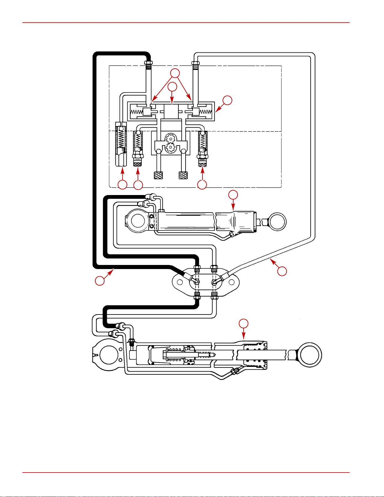
Power Trim Hydraulic Schematic
9
1
2
4 6
3
5
7
1-Shuttle
2-Pump Adaptor
3-UP/OUT Pressure Relief Valve
4-Thermal Relief Valve
5-Trim Cylinder
6-IN/DOWN Pressure Relief Valve
7-UP/OUT Hose
8-IN/DOWN Hose
9-Poppet Valves
8
5
73552
Page 1C-20 90-818177--3 APRIL 2001
Page 53

SERVICE MANUAL NUMBER 14
TROUBLESHOOTING
Auto Trim II Electrical System
NOTE:Refer to “Auto Trim II System Wiring Diagram.”
Pump Motor Will Not Run UP Or DOWN In Either Manual Or Auto Mode
SOLENOIDS CLICK
Cause Special Instructions
Pump positive battery cable connection
loose or corroded.
110 amp fuse blown or loose or corroded
solenoid connection.
Pump motor brushes stuck, corroded or
worn out.
Armature commutator dirty. Clean or replace.
Armature faulty. Test and replace if bad.
Field and frame faulty. Test and replace if bad.
Pump gears frozen. Replace pump.
Trim harness shorted between UP and
DOWN circuit.
SOLENOIDS DO NOT CLICK
Pump negative battery cable loose,
corroded or damaged.
Mode switch wiring harness connector is
loose at pump.
Faulty thermal circuit breaker in pump
motor.
Open circuit in mode switch wiring
harness.
No power to mode switch.
Faulty mode switch.
Check cable 14.
Check for voltage at terminal 5.
Clean or replace.
Disconnect blue-white lead 2 from
solenoid terminal. If pump motor will now
run in the DOWN direction, a short in the
harness is indicated.
Cause Special Instructions
Check cable 13 for damage or a loose or
corroded connection.
Secure connection 47.
Connect a jumper wire between terminals
1 and 7. If pump now operates, circuit
breaker is faulty and field and frame
assembly must be replaced.
With ignition switch in RUN position and
mode switch in MANUAL mode, check for
voltage at terminal 8 while trimming UP
and terminal 12 while rimming DOWN. If
no voltage is indicated, refer to items 5
and 6 immediately following.
Check for voltage at terminal 25 (with
ignition switch in RUN position). If no
voltage is indicated, check power lead for
a poor connection.
Check for voltage at terminal 24 (with
mode switch in AUTO mode) and terminal
26 (with switch in the MANUAL mode).
Replace switch if no voltage is indicated.
90-818177--3 APRIL 2001 Page 1C-21
Page 54

TROUBLESHOOTING SERVICE MANUAL NUMBER 14
Pump Motor Will Not Stop Running Down In Auto Mode
TRIM UP/OUT SWITCH AND TRAILER SWITCH INOPERATIVE IN MANUAL MODE
NOTE:An internal timer in the control module stops the pump motor 50 seconds after this
problem condition occurs.
Cause
Loose or dirty solenoid connection. Check connections 7 and 8.
Check for voltage at terminal 8 while
trimming UP (in MANUAL mode). If
Faulty solenoid.
Loose or corroded trim limit switch lead
connections.
Faulty trim limit switch.
Open circuit in wiring harness.
Faulty control module. Replace.
voltage exists, an open condition in
solenoid is indicated and solenoid must be
replaced. If no voltage is indicated, refer to
steps 3 through 6 following.
Check connections 32 and 36.
Disconnect trim limit switch leads 32 and
36 and connect a continuity meter
between leads. Continuity should exist
with drive unit in DOWN position. If not,
readjust or replace switch as necessary.
Check leads 30, 35, 46 and 2 for loose or
corroded connections or damage.
Pump Motor Will Not Run Up Or Down In Auto Mode
MANUAL MODE FUNCTIONS PROPERLY
Special Instructions
Cause Special Instructions
Control module 20 amp fuse blown.
Open in control module battery cables or
wiring harness.
Faulty mode switch.
Faulty control module. Replace.
Determine cause for blown fuse and
correct before replacing fuse.
Check cables 16 and 18 and lead 20.
Check for voltage at terminal 24 and 25
with switch in AUTO mode. If voltage
exists at terminal 25, but not 24, switch is
faulty.
Page 1C-22 90-818177--3 APRIL 2001
Page 55

SERVICE MANUAL NUMBER 14
TROUBLESHOOTING
Trim System Completely Inoperative In Manual Mode
AUTO MODE FUNCTIONS PROPERLY
Cause Special Instructions
Check for voltage at terminal 26 with
Faulty mode switch.
Open circuit in wiring harness.
mode switch in MANUAL mode. If no
voltage is indicated, replace switch.
Check leads 27 and 33 for loose or
corroded connections or damage.
Pump Motor Will Run UP, But Not DOWN In Both Manual And Auto Modes
DOWN SOLENOID DOES NOT CLICK
Cause Special Instructions
Loose or dirty solenoid connections. Check connections 4, 7 and 12.
Check for voltage at terminal 12 while
trimming Down (in MANUAL mode). If no
voltage is indicated, repeat test at terminal
Faulty mode switch or open in DOWN
circuit.
22 and 23. If voltage exists at terminal 23,
but not at 22, switch is faulty. If voltage is
present at terminal 22, check leads 3 and
48 and connector 47 for an open
condition.
Faulty DOWN solenoid. Replace solenoid.
DOWN SOLENOID CLICKS
Cause Special Instructions
Loose or dirty solenoid connections. Check connections 10 and 11.
Check for voltage at terminal 11 while
Faulty solenoid.
Faulty DOWN field winding. Replace field and frame.
trimming Down (in MANUAL mode). If no
voltage is indicated, replace solenoid.
Pump Motor Runs DOWN, But Not UP In Both The Manual And Auto Modes
UP SOLENOID CLICKS
Cause Special Instructions
Loose or dirty solenoid connections. Check connections 5 and 6.
Check for voltage at terminal 6 while
Faulty solenoid.
Faulty UP field winding. Replace field and frame.
trimming UP. If no voltage is indicated,
replace solenoid.
90-818177--3 APRIL 2001 Page 1C-23
Page 56

TROUBLESHOOTING SERVICE MANUAL NUMBER 14
Pump Motor Will Run DOWN, But Not UP In Auto Mode
MANUAL MODE FUNCTIONS PROPERLY
Cause Special Instructions
Open circuit in control module sense
lead.
Faulty control module. Replace.
Check lead 17 for loose or corroded
connections or damage.
Pump Motor Will Run UP, But Not DOWN In Auto Mode
MANUAL MODE FUNCTIONS PROPERLY
Cause Special Instructions
Check for voltage at terminal 21 and 22
Faulty mode switch.
Open circuit in wiring.
Faulty control module. Replace.
while turning ignition switch to RUN
position (in AUTO mode). If voltage exists
at 21 but not at 22, switch is faulty.
Check lead 19 for a loose or corroded
connection or damage.
Trim DOWN/IN Switch Inoperative In Manual Trim Control
TRIM UP/OUT SWITCH AND TRAILER SWITCH FUNCTION, AUTO MODE FUNCTIONS
PROPERLY
Cause Special Instructions
Faulty DOWN switch in manual trim
control.
Open circuit in wiring harness.
Faulty mode switch.
Check for voltage at terminal 38 while
trimming DOWN (in MANUAL mode). If no
voltage is indicated, switch is faulty.
Check for voltage at terminal 23 while
trimming DOWN. If no voltage is present,
check leads 28 and 34 for a loose or
corroded connection or damage.
Check for voltage at terminal 22 while
trimming DOWN. If no voltage exists,
switch is faulty.
Page 1C-24 90-818177--3 APRIL 2001
Page 57

SERVICE MANUAL NUMBER 14
Trim UP/OUT Switch Inoperative In Manual Trim Control
TRIM DOWN/IN SWITCH FUNCTIONS, AUTO MODE FUNCTIONS PROPERLY
Cause Special Instructions
TROUBLESHOOTING
Trim 20 amp fuse “43” blown (if equipped).
Open in power supply lead to trim and
trailer switch.
Faulty trim UP/OUT switch (applies only to
trim controls where it is necessary to
actuate trim UP switch in order for trailer
switch to function).
Determine cause for blown fuse and
correct before replacing fuse.
Check voltage at terminal 44. If no voltage
is indicated, check lead 45 for a poor
connection or damage.
Check for voltage at terminal 40 while
actuating trim UP/OUT switch. Replace
switch if no voltage is indicated.
Trailer Switch In Manual, Trim Control Inoperative
TRIM UP/OUT SWITCH FUNCTIONS
Cause Special Instructions
Check for voltage at terminal 41 and 42
while actuating trailer switch. If voltage
Faulty trailer switch.
Opening in wiring.
exists at terminal 42, but not at terminal
41, a faulty switch is indicated. If no
voltage exists at terminal 42, check power
supply lead for an opening.
Check lead 39 for damage or a loosened
or corroded connection.
Boat Is On Plane Well Before Drive Unit Begins To Trim Out
Cause Special Instructions
Control module adjustment incorrect. Adjust. (Refer to SECTION 5)
Faulty control module. Replace control module.
Boat Is Not On Plane Before Drive Unit Begins To Trim Out
Cause Special Instructions
Control module adjustment incorrect. Adjust. (Refer to SECTION 5)
Faulty control module. Replace control module.
90-818177--3 APRIL 2001 Page 1C-25
Page 58
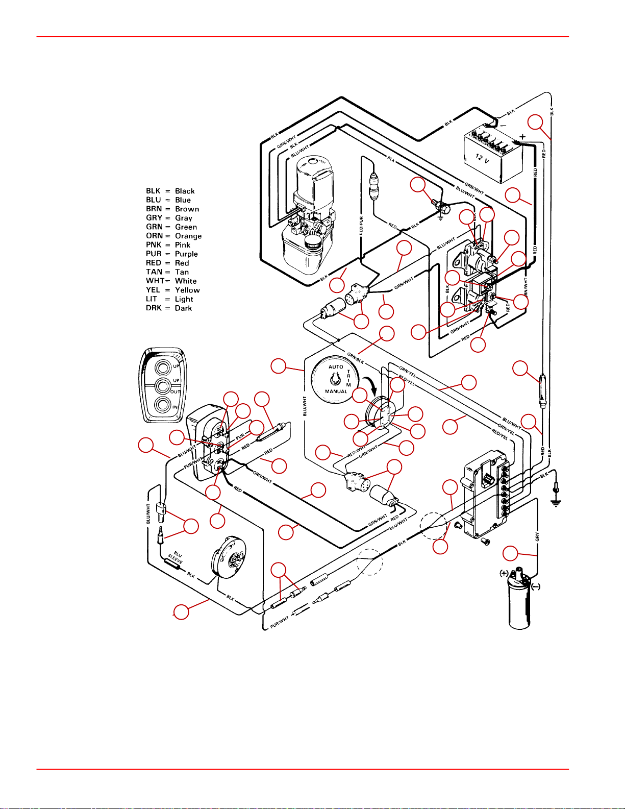
TROUBLESHOOTING SERVICE MANUAL NUMBER 14
Auto Trim II System Wiring Diagram
18
1
14
8
7
39
40
36
38
37
41
42
44
43
46
45
32
33
34
27
13
25
47
24
26
48
2
9
23
12
4
11
19
20
30
31
3
21
22
28
29
6
5
10
15
16
17
35
22178
Corrosion Protection
NOTE:Refer to “MerCathode Controller Wiring Diagram.”
Page 1C-26 90-818177--3 APRIL 2001
Page 59

SERVICE MANUAL NUMBER 14
TROUBLESHOOTING
Corrosion On Underwater Parts, Without MerCathode Or Impressed Current
Protection
Cause Special Instructions
Sacrificial anode(s) consumed. Replace anode(s) when 50% consumed.
Stainless steel propeller installed.
Sacrificial anode(s) not grounded to drive.
Loss of continuity between underwater
parts & ground.
Shore power causing overload of anode(s)
and/or MerCathode.
Paint on drive heavily worn (exposing
more metal).
Add MerCathode (impressed current
protection) or additional sacrificial anodes.
Remove anode(s), clean contact surface,
reinstall and check continuity.
Provide good ground connections.
Disconnect shore power or install
Quicksilver isolator.
Prime and repaint and/or install additional
anode(s).
Sacrificial anode(s) painted. Remove paint or replace anode(s).
Drive tilted so far that anode(s) are out of
the water.
Only power trim cylinders are corroded.
Corrosion in area of exhaust outlets.
Exhaust deposits can cause corrosion.
Corrosion occurring after unit removed
from saltwater.
Corrosion and/or salt build up between
mating parts.
Leave drive down, install additional anode
(below waterline) or transom mount a
MerCathode.
Provide good ground to drive. All parts
must be grounded.
Remove deposits with marine or auto wax.
Wash exterior and flush interior with fresh
water.
Exclude moisture from between mating
parts with Quicksilver 2-4-C with Teflon.
Stainless Steel parts corroding:
Tightly wrapped fishing line or foreign
material excludes oxygen, causing
corrosion.
Iron particles, such as from a wire brush,
Clean parts, remove foreign material,
ensure continuity.
cause rusting.
Propeller pitting can occur if electrical
continuity is lost.
90-818177--3 APRIL 2001 Page 1C-27
Page 60

TROUBLESHOOTING SERVICE MANUAL NUMBER 14
Corrosion On Underwater Parts, With MerCathode Or Impressed Current
Protection
DRIVE CORRODING
Cause Special Instructions
Poor connection between reference
electrode (BRN) lead or anode (ORN) lead
and MerCathode controller.
Faulty MerCathode reference electrode.
Faulty MerCathode controller.
Too much cathode (such as stainless
steel).
Loss of continuity between sterndrive
components and ground.
Sacrificial anodes consumed, painted or
inoperative.
MerCathode reference electrode or anode
painted.
Clean and/or tighten connection. Repair
wiring.
Disconnect reference electrode lead
(BRN) from the controller “R” terminal.
Connect the lead to positive (+) terminal of
a digital multi-meter (set on 0-2000
millivolt scale). Connect negative (–) meter
lead to negative (–) battery terminal. Note
meter reading; then repeat the test with a
test silver/silver chloride reference
electrode held behind the drive. The same
reading should be obtained in both cases.
If not, replace the reference electrode.
With anode and reference electrode leads
connected to controller, connect a jumper
wire between “R” and negative(–)
terminals on controller. Connect positive
(+) lead of volt meter (set on 0-20 scale) to
“A” terminal on controller. Connect the
negative (–) meter lead to the negative (–)
controller terminal. Reading should be as
follows:
D Freshwater Areas = 11.5 volts
minimum
D Seawater Areas = 3.55 volts
minimum
If the reading is low, replace the controller.
MerCathode system overpowered by large
quantity of stainless steel below the
waterline.
Ensure continuity (check continuity wires
and washers).
Replace anodes.
Remove paint or replace anode or
MerCathode reference electrode.
Page 1C-28 90-818177--3 APRIL 2001
Page 61

SERVICE MANUAL NUMBER 14
DRIVE CORRODING - CONTINUED
Cause Special Instructions
No power to MerCathode controller.
TROUBLESHOOTING
Connect positive (+) lead of volt meter (set
on 0-20 volt scale) to positive (+) terminal
on the controller and negative (-) volt
meter lead to negative (-) terminal. Meter
should indicate battery voltage. Check for
blown fuse (if equipped) on a standard
MerCathode system. Clean the connection
or repair wiring as required.
Check the fuse in the hot lead.
Check battery.
MerCathode system not functioning
Check for loose connections at controller
and battery
Check the grounding wire between the
drive and the controller.
90-818177--3 APRIL 2001 Page 1C-29
Page 62

TROUBLESHOOTING SERVICE MANUAL NUMBER 14
Corrosion On Underwater Parts, With MerCathode Or Impressed Current
Protection
DRIVE OVER-PROTECTED
Cause Special Instructions
Disconnect reference electrode lead
(BRN) from “R” terminal on controller.
Connect the lead to the positive (+)
terminal of a digital multimeter (set on
0-2000 millivolt scale). Connect the
Faulty MerCathode reference electrode.
Faulty MerCathode controller.
Stray current corrosion (electrical current
leaves a metal conductor and creates a
path through the water).
Poor connection between the MerCathode
reference electrode lead (BRN) and the
“R” terminal on the controller.
negative (-) meter lead to the negative (-)
battery terminal. Note the meter reading;
then repeat the test with a test silver/silver
chloride reference electrode held behind
the drive. The same reading should be
obtained in both cases. If not, replace the
reference electrode.
Check controller output. If the hull
potential indicates overprotection, remove
the reference electrode lead from the
controller. If the controller is off (no
impressed current called for) the voltage
between the negative (BLK) and the
between the negative (BLK) and the
anode should be less than 1 volt. Measure
amperage; with the reference electrode
disconnected, the amperage between the
negative on the controller and the anode
terminal should be less than 1 milli-amp.
Replace the controller if needed.
Disconnect electrical components one at a
time and observe the multimeter reading
until you eliminate the high reading.
Correct the source of the stray current.
Clean and/or tighten the connection.
Repair wiring as needed.
Check the fuse in the hot lead.
Check the battery.
MerCathode system not functioning.
Page 1C-30 90-818177--3 APRIL 2001
Check for loose connections at
controller and battery.
Check the grounding wire between the
sterndrive and the controller.
Page 63

SERVICE MANUAL NUMBER 14
Testing Procedure for Corrosion Protection
1. Unplug shore power (if equipped).
2. Measure hull potential with silver/silver chloride reference electrode and digital volt/ohm
meter.
READINGS
TROUBLESHOOTING
Potential Diagnosis
Saltwater
Freshwater
CORROSION SYMPTOMS
• Paint blistering (usually on sharp edges)
• Loosely adhering white corrosion products on exposed aluminum surfaces (do not
confuse these with tenaciously clinging calcium carbonate deposits)
Below 850 millivolts
Drive is corroding.
(Refer to “Drive Corroding”)
Between 850 - 1100
millivolts
Above 1100 millivolts
Drive is protected
Drive is overprotected.
(Refer to “Drive Corroding”)
Potential Diagnosis
Below 750 millivolts
Drive is corroding.
(Refer to “Drive Corroding”)
Between 750 - 1050
millivolts
Above 1050 millivolts
Drive is protected
Drive is overprotected.
(Refer to “Drive Corroding”)
• Aluminum pitting
90-818177--3 APRIL 2001 Page 1C-31
Page 64

TROUBLESHOOTING SERVICE MANUAL NUMBER 14
MerCathode Controller
a
b
c
a-Controller
b-20 Amp Fuse
c-Electrode
73596
Page 1C-32 90-818177--3 APRIL 2001
Page 65
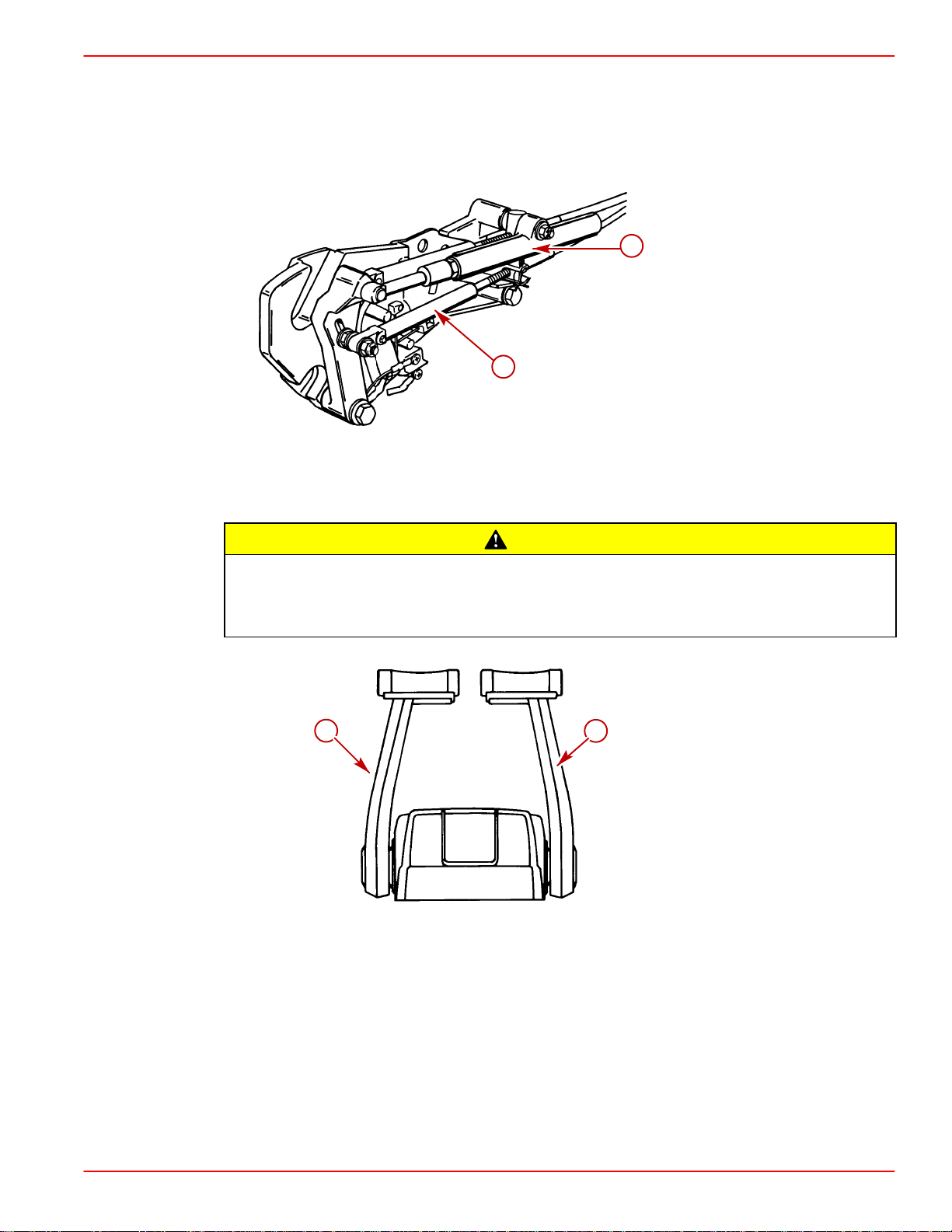
SERVICE MANUAL NUMBER 14
Shift System Troubleshooting
NOTE:Some models may be equipped with a shift assist assembly. The only difference with
these models is that the remote control shift cable attaching hardware is slightly longer. Shift
cable adjustment is the same as all other versions.
a-Shift Assist Assembly
b-Remote Control Shift Cable
TROUBLESHOOTING
a
b
50308
CAUTION
If the boat is equipped with A REMOTE CONTROL THAT HAS SEPARATE SHIFT AND
THROTTLE LEVERS, this shift assist assembly should NOT be used. The use of the
shift assist assembly with this type of remote control can cause the shift lever to
move out of gear unexpectedly.
a
a-Shift Lever
b-Throttle Lever
b
23159
90-818177--3 APRIL 2001 Page 1C-33
Page 66

TROUBLESHOOTING SERVICE MANUAL NUMBER 14
Troubleshooting Shift Problems
NOTE:The following information is provided to assist an installer in troubleshooting if hard
shifting or chucking/racheting is encountered when shifting into forward gear.
1. When installing the control box in the side panel of the boat, make sure that the cables
have enough clearance to operate. This is necessary because the cables move up and
down when the shift handle is moved. If the control box is mounted too far back toward
any fiberglass structure, the cables will be interfered with. This will cause very hard
shifting.
NOTE:The control box housing can be rotated in 30° increments to improve cable routing.
74688
74689
Proper Cable Bend Improper Cable Bend
2. Make sure that when the shift cable from the control box is led through the side gunnel
of the hull, it does not have any extremely sharp bends in it as this will cause the stiff
shifting.
3. Before installing the shift cable into the control box, extend the stainless rod eye end of
the cable and grease it with 2-4-C Marine Lubricant with Teflon. Move it back and forth
to allow even distribution of the grease.
22005
4. Do not strap or clamp the control cables to any other cables or rigid structure within
3 ft. (914 mm) of the control box.
5. Be sure the cable is not permanently kinked.
6. Make sure there is proper clearance for cable movement when the control box is
installed in the side panel. The cables must have room to move up and down when the
control handle is shifted into either forward or reverse.
7. Ensure that the engine was not set down on the intermediate shift cable during
installation, as this will crush the inner cable tubing and cause improper and/or stiff
shifting.
Page 1C-34 90-818177--3 APRIL 2001
Page 67
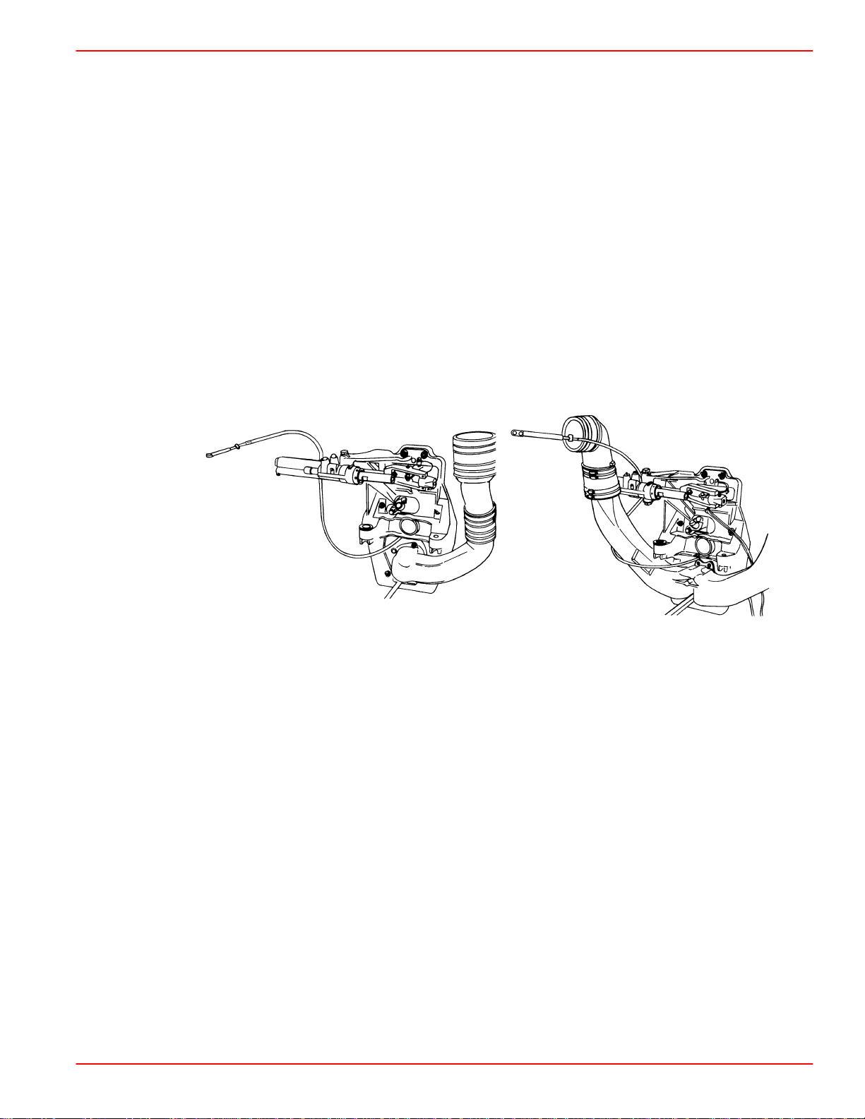
SERVICE MANUAL NUMBER 14
8. DO NOT fasten the shift cable with straps or clamps to any other cable within 5 ft.
(1524 mm) of the shift plate.
9. DO NOT fasten the shift cable to the transom with any type of plastic clips or fasteners
within 5 ft. (1524 mm) of the shift plate.
10. DO NOT over tighten the throttle or shift cable attaching nuts at the engine end. Barrel
and cable end must be free to rotate on the mounting stud.
11. Check the intermediate shift cable routing from the transom assembly to the shift plate
as follows:
a. The cable should come through the transom, above the exhaust pipe and make a
b. The cable should then be routed under the starboard rear engine mount and turned
c. Then route the cable behind the power steering valve and loop over to the shift plate
Following this routing will prevent the engine coupler from damaging the cable.
TROUBLESHOOTING
turn toward the starboard side of the boat between the exhaust pipe and the engine
flywheel housing.
toward the transom.
on the engine. Connect it to the anchor points on the shift plate.
74903
4 Cylinder Inline Model V6 and V8 Models
74901
90-818177--3 APRIL 2001 Page 1C-35
Page 68
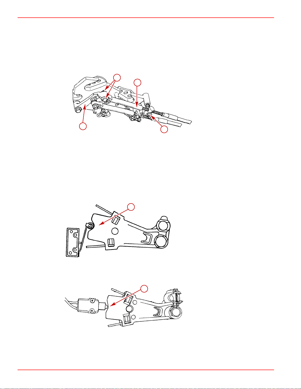
TROUBLESHOOTING SERVICE MANUAL NUMBER 14
Checking for Excessive Play
Checking for excessive play in the drive unit shift system can be done with the boat in the
water or on land. Refer to the appropriate procedure:
BOAT OUT OF WATER (ENGINE OFF)
1. Disconnect remote control shift cable.
c
a
b
d
a-Remote Control Shift Cable
b-Plastic Shift Lever
c-Clevis Pin and Cotter Pin
d-Locknut and Washer
IMPORTANT: When pushing or pulling on drive unit shift cable in the following steps,
apply just enough pressure so that V-notch starts moving. Then ease up slightly. Use
a fine tip marking device to mark threaded tube to obtain an accurate measurement.
22267
a
22058
Roller Type Switch
a-V-notch
a
75225
Plunger Type Switch
a-V-notch
2. Check for excessive play in drive unit shift system:
Page 1C-36 90-818177--3 APRIL 2001
Page 69
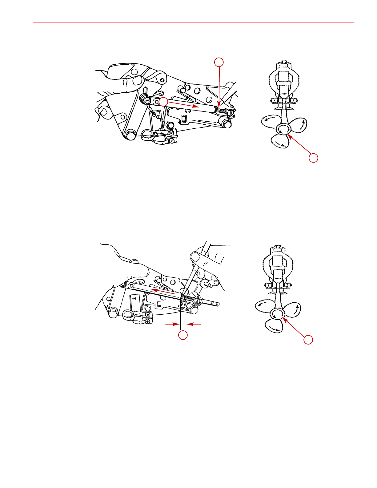
SERVICE MANUAL NUMBER 14
a. Place drive unit into gear by pushing in on drive unit shift cable while rotating
b. Place a mark on shift cable threaded tube against edge of end guide.
TROUBLESHOOTING
propeller shaft counterclockwise until it stops to ensure full clutch engagement.
c
a
50499
b
22266
a-Drive Unit Shift Cable
b-Propeller Shaft - Rotate
c-Threaded Tube - Mark Here
c. While maintaining pressure on propeller shaft in a counterclockwise direction (to
keep clutch locked with gear), lightly pull out on drive unit shift cable end guide and
place another mark on threaded tube.
d. Measure distance between both marks. Distance should be 9/16 in. (14 mm) or
less.
a
b
a-9/16 in. (14 mm) Or Less
b-Propeller Shaft - Maintain Pressure
If play is 9/16 in (14 mm) or less: No further attention to drive unit is needed. Proceed with
adjustments.
If play is more than 9/16 in. (14 mm): Drive unit must be removed to further isolate
excessive play.
90-818177--3 APRIL 2001 Page 1C-37
22266
Page 70
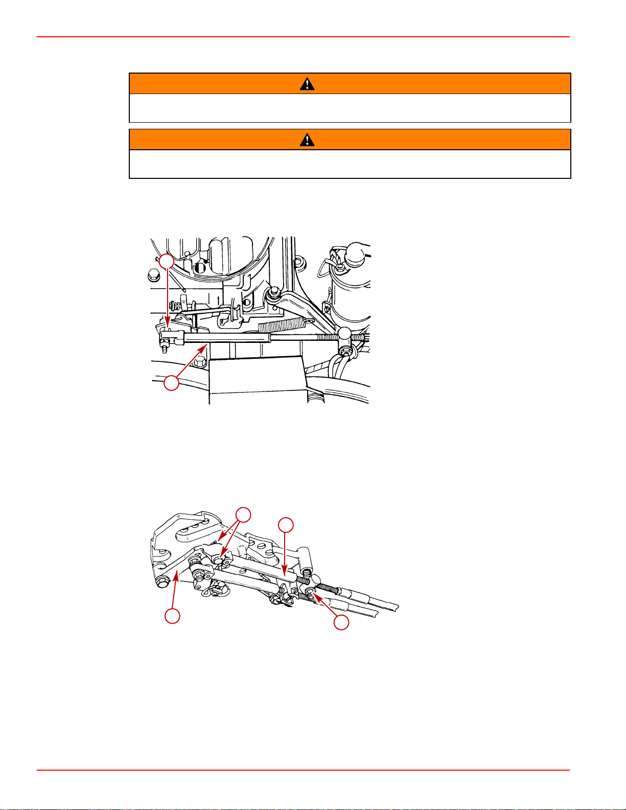
TROUBLESHOOTING SERVICE MANUAL NUMBER 14
BOAT IN WATER (ENGINE RUNNING)
WARNING
At least two people will be needed for the following procedure, one person to check
the adjustment and one person to stay at the control station of the boat.
WARNING
Ensure boat is secured to dock and precautions have been taken to avoid damage
to boat prior to placing drive unit into gear.
1. Start engine and let it warm up to normal operating temperature (Refer to operating
procedures in Operation and Maintenance Manual).
2. Disconnect throttle cable.
b
a
Carburetor Model Shown (Others Similar)
a-Throttle Cable End Guide
b-Carburetor Throttle Lever
3. Disconnect Remote Control Shift Cable.
c
a
b
a-Remote Control Shift Cable
b-Plastic Shift Lever
c-Clevis Pin And Cotter Pin
d-Locknut And Washer
d
22062
22267
Page 1C-38 90-818177--3 APRIL 2001
Page 71
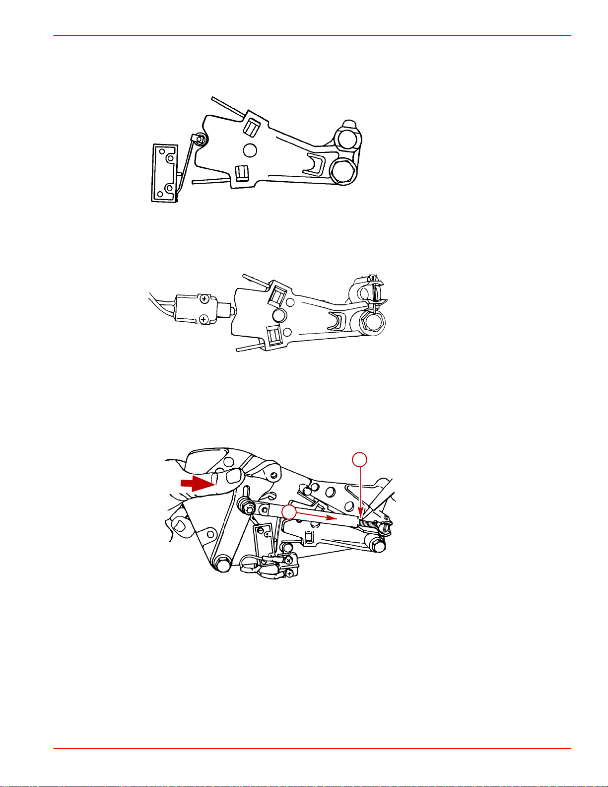
SERVICE MANUAL NUMBER 14
IMPORTANT: When pushing or pulling on drive unit shift cable, in the following steps,
apply just enough pressure so that V-notch moves; then ease up slightly. Use a fine
tip marking device to mark threaded tube to obtain an accurate measurement.
Roller Type Switch
TROUBLESHOOTING
22058
Plunger Type Switch
4. Check for excessive play in drive unit shift system as follows:
a. Push in on drive unit shift cable.
b. Place a mark on shift cable threaded tube against cable end guide.
b
a
a-Drive Unit Shaft Cable
b-Threaded Tube
75225
50499
c. Lightly pull on drive unit shift cable end guide and place another mark on threaded
tube.
90-818177--3 APRIL 2001 Page 1C-39
Page 72
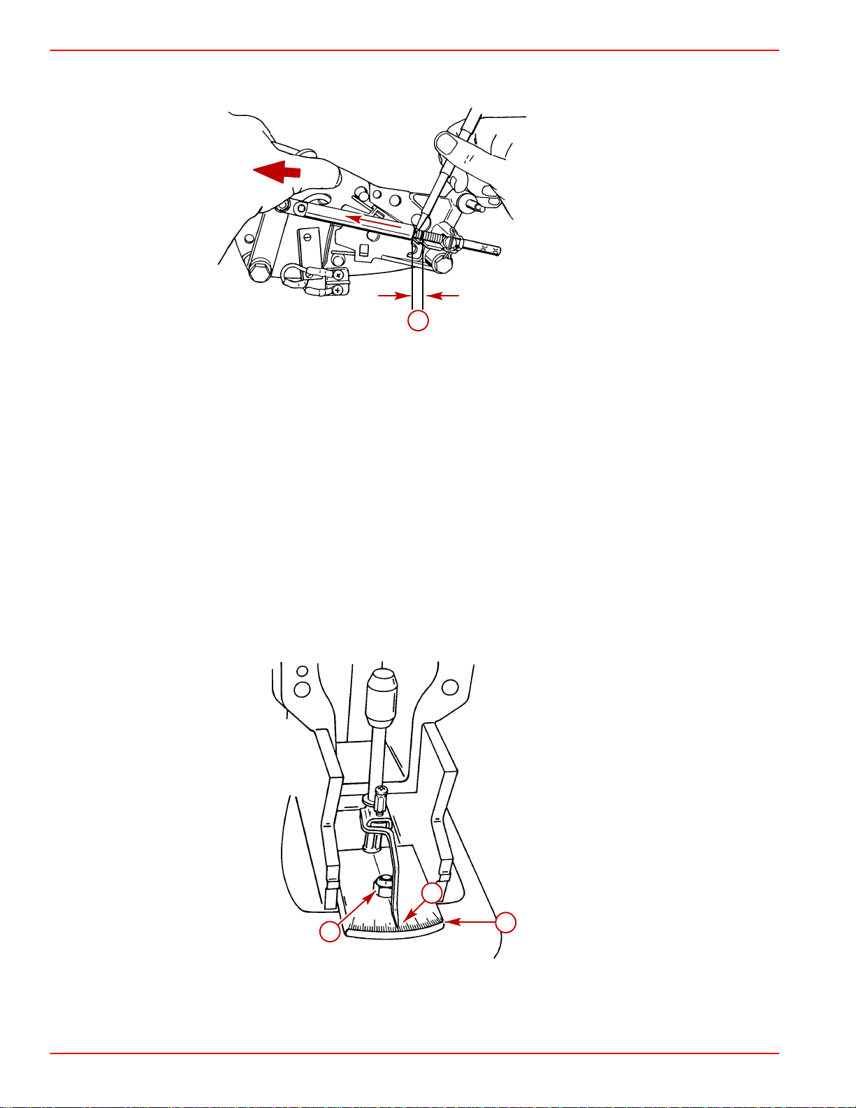
TROUBLESHOOTING SERVICE MANUAL NUMBER 14
d. Measure distance between both marks. Distance should be 9/16 in. (14 mm) or
less.
a-9/16 in (14 mm) Or Less
If play is 9/16 in. (14 mm) or less: No further attention to drive unit is needed. Proceed with
adjustments.
If play is more than 9/16 in. (14 mm): Drive unit must removed to further isolate excessive
play.
Isolating Excessive Play
NOTE:Refer to the end of this section for templates and patterns needed to fabricate similar
tools.
1. To determine shift shaft rotational end play, use a tool such as the one shown, to
measure degrees of play in the shift shaft, with clutch locked and held in gear.
NOTE:Tool pattern on p. 1C - 45.
a. While maintaining pressure on propeller shaft to keep clutch locked with gear, lightly
turn shift shaft coupler counterclockwise. Make note of pointer location.
a
50497
a
c
a-Pointer - Installed on Shift Shaft
b-Scale (1_ Increments)
c-Nut - Hand Tight Only
Page 1C-40 90-818177--3 APRIL 2001
b
50498
Page 73
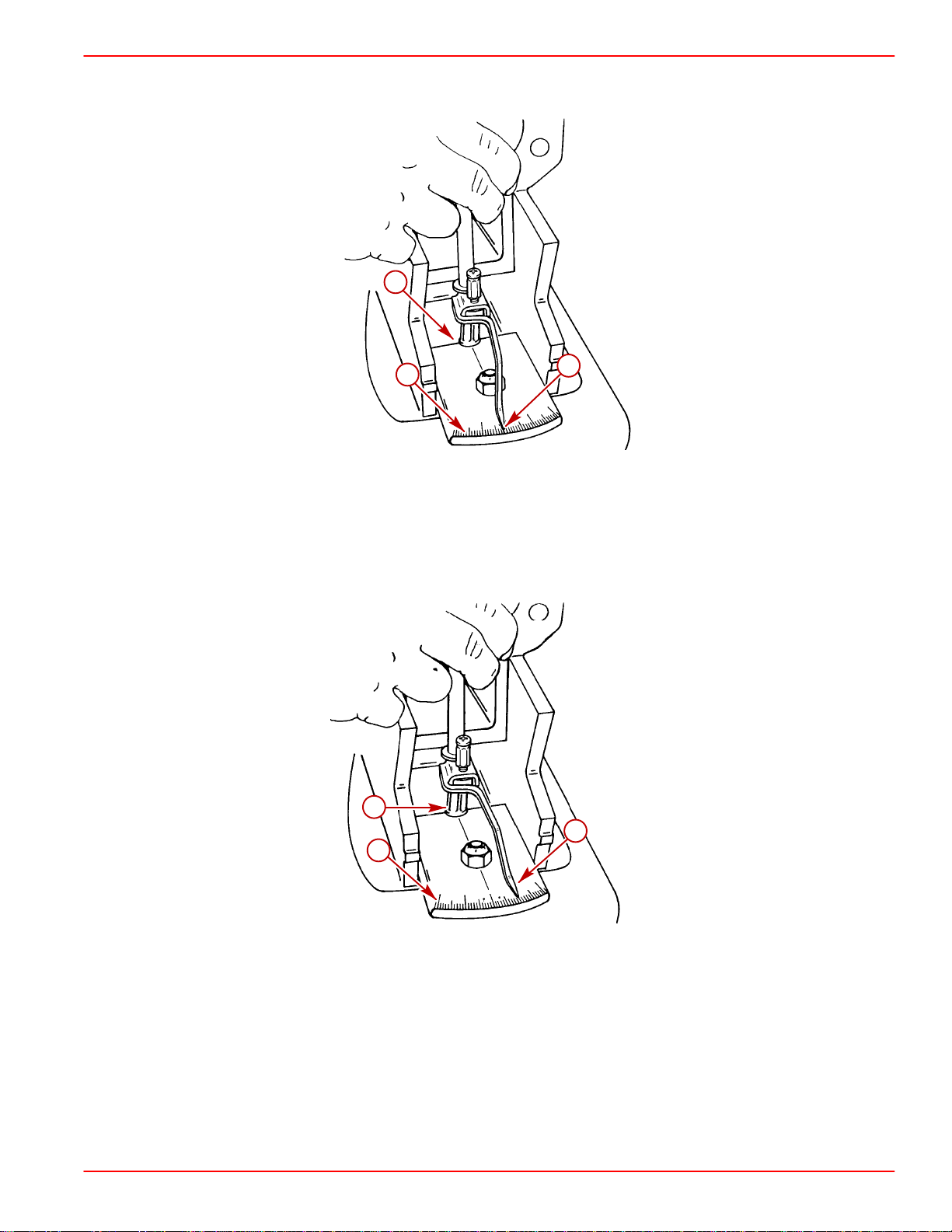
SERVICE MANUAL NUMBER 14
b. Rotate shift shaft coupler clockwise while simultaneously turning propeller shaft
TROUBLESHOOTING
counterclockwise until clutch locks into gear. Make note of pointer location on scale.
a
c
b
50498
a-Shift Shaft Coupler
b-Pointer
c-Scale
c. While maintaining pressure on propeller shaft to keep clutch locked with gear, lightly
turn shift shaft coupler counterclockwise. Make note of pointer location.
a
b
c
50498
a-Shift Shaft Coupler
b-Pointer
c-Scale
d. Determine total degrees of movement.
If 12_ or less: problem is with the drive unit shift cable, upper shift shaft assembly and lever
assembly.
If more then 12_: problem is with gear case shift spool assembly.
Whichever the case, refer to appropriate section for repair of applicable components.
90-818177--3 APRIL 2001 Page 1C-41
Page 74

TROUBLESHOOTING SERVICE MANUAL NUMBER 14
Checking Remote Control Shift Cable Output
IMPORTANT: Remote control must provide a shift cable travel (at the shift plate end)
of 2-7/8 in. (73 mm) to 3-1/8 in. (80 mm) with a 15-20 lb. (6.8-9 kg) load applied to the
cable end guide.
Models W ith Shift Assist:
shift cable and using the shift assist assembly (provided) to place the proper load on the shift
cable (drive unit shift cable should not be installed).
Models Without Shift Assist:
pulling on the remote guide, to place the proper load, [15-20 lb. (6.8-9Kg)], on the shift cable.
1. Place remote control into gear:
Right Hand Rotation Drive Unit - Forward gear wide-open-throttle position.
Left Hand Rotation Drive Unit - Reverse gear wide-open-throttle position.
Place a mark on threaded tube against edge of cable end guide.
2. Place remote control into the opposite gear. Measure the distance between the edge
of the shift cable end guide and the mark line in step 1. Total shift cable output must not
be less than 2-7/8 in. (73 mm) or more than 3-1/8 (80 mm). If output is incorrect, remote
control and/or shift cable must be replaced.
This measurement can be taken by installing the remote control
This measurement can be taken by lightly pushing and
d
b
a
With Shift Assist Assembly
a-Shift Assist Assembly
b-Remote Control Shift Cable - Retracted
c-Place a Mark On Tube Against Edge Of Cable End Guide
d-Remote Control Shift Cable - Extended
e-Measurement Taken from Mark To Edge Of Cable End
Guide: 2-7/8 in. (73 mm) To 3-1/8 in. (80 mm)
a
c
e
50368
Page 1C-42 90-818177--3 APRIL 2001
Page 75

SERVICE MANUAL NUMBER 14
TROUBLESHOOTING
c
a
b
a
e
Without Shift Assist Assembly
a-Shift Cable end Guide
b-Remote Control Shift Cable - Lightly Pull On End Guide
c-Place A Mark On Tube Against Edge Of Cable End Guide
d-Remote Control Shift Cable - Lightly Push In On End Guide
e-Measurement Taken From Mark To Edge Of Cable End
Guide 2-7/8 in. (73 mm) to 3-1/8 in. (80 mm)
d
50499
Checking Cutout Switch Timing (Models With Roller Type Switch)
1. Disconnect Cutout Switch WHITE/GREEN wire from terminal block or bullet conector.
2. Connect ohmmeter positive (+) lead to cutout switch WHITE/GREEN wire and
ohmmeter negative (–) lead to cutout switch black wire at terminal block.
3. Set Ohmmeter on Rx1 scale.
c
a
b
a-Terminal Block
b-Cutout Switch WHITE/GREEN Wire
c-Cutout Switch BLACK Wire
50497
90-818177--3 APRIL 2001 Page 1C-43
Page 76

TROUBLESHOOTING SERVICE MANUAL NUMBER 14
NOTE:Refer to the end of this section for the pattern and dimensions needed to fabricate
a similar tool.
Slowly move cutout switch roller off of its seat. Circuit should close (full continuity reading)
when roller is moved 1/8 in. (3 mm). Use the 1/8 in. rod on the end of special tool to gauge
this movement.
b
a
50497
a-Special Tool
b-1/8 in. (3 mm)
If switch closes too early (less than 1/8 in.): Roller must be bent away from its seat.
If switch closes too late (more than 1/8 in.): Roller must be bent toward its seat.
c
a
b
50499
a-Lever
b-Roller
c-Special Tool
Page 1C-44 90-818177--3 APRIL 2001
Page 77

SERVICE MANUAL NUMBER 14
4. Once cutout switch is timed properly, reconnect wires at terminal block and coat
terminals with Liquid Neoprene.
TROUBLESHOOTING
a
b
a-BLACK Wires
b-WHITE/GREEN Wires
Checking Cutout Switch Timing (Models With Plunger Type Switch)
1. While holding the retainer nuts on the back of the shift plate, loosen the two phillips head
screws on the shift cutoff switch and slowly move the switch either forward or aft.
c
b
a
d
a-Switch/Plunger Pin
b-Activating Lever Assembly
c-1/32’in. (0.8 mm) Adjustment
d-Two Screws
50499
75225
90-818177--3 APRIL 2001 Page 1C-45
Page 78
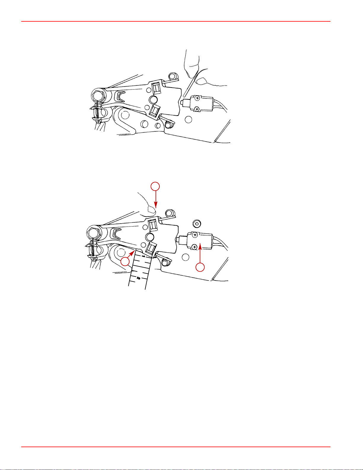
TROUBLESHOOTING SERVICE MANUAL NUMBER 14
2. Adjust switch to locate plunger pin to 1/32 in (0.8 mm). between plunger pin and
activating lever assembly.
75679
3. Slowly move activating lever assembly off until cutout switch opens or closes. Circuit
should open or close when the activating lever assembly is moved 3/16 +/– 1/32 in.
(4.8 +/– 0.8 mm).
b
b
a
75225
a-Cutout Switch
b-Movement of Activating Lever Assembly
4. After adjustments are made and are within 3/16 +/– 1/32 in. (4.8 +/– 0.8 mm), tighten
the screws on the cutout switch. After tightening screws, recheck the plunger pin
position.
Page 1C-46 90-818177--3 APRIL 2001
Page 79

SERVICE MANUAL NUMBER 14
Checking Operation
1. Reconnect throttle cable.
2. Place boat in water and start engine. Check the following:
a. Shift into forward and reverse gear, verify clutch engages before engine begins to
b. Accelerate engine in forward and reverse gear to ensure engine does not shut down.
c. Check that shift cutout switch roller is centered in notch of shift cutout lever, with drive
d. Shift from IN gear position to neutral, ensure drive unit is in neutral before remote
TROUBLESHOOTING
accelerate.
unit in forward and reverse gear.
control shift lever comes to neutral detent position.
90-818177--3 APRIL 2001 Page 1C-47
Page 80

TROUBLESHOOTING SERVICE MANUAL NUMBER 14
THIS PAGE IS INTENTIONALLY BLANK
Page 1C-48 90-818177--3 APRIL 2001
Page 81

SERVICE MANUAL NUMBER 14
POINTER
TROUBLESHOOTING
SIDE VIEW
BEND AS SHOWN
TOP VIEW
5 - 1/2 in. (140mm)
1/16 in. (1.6mm) Dia. STIFF WIRE
1/16 in.
(1.6mm)
SCALE
PASTE TO HEAVY
CUTOUT SWITCH
ADJUSTMENT TOOL
STOCK PAPER OR CARDBOARD
50375
90-818177--3 APRIL 2001 Page 1C-49
(3mm)
1/8 in. Dia.
Page 82

TROUBLESHOOTING SERVICE MANUAL NUMBER 14
THIS PAGE IS INTENTIONALLY BLANK
Page 1C-50 90-818177--3 APRIL 2001
Page 83

SERVICE MANUAL NUMBER 14
REMOVAL, INSTALLATION AND ADJUSTMENT
Table of Contents
REMOVAL, INSTALLATION AND ADJUSTMENTS
Section 2A - All Models
2
Sterndrive Unit Removal 2A-2. . . . . . . . . . . . .
Sterndrive Unit Installation 2A-6. . . . . . . . . . . .
Remote Control Shift Cable
Adjustment (Drive Unit Installed) 2A-13. . . . . .
Troubleshooting Shift Problems 2A-22. . . . .
Propeller Installation 2A-23. . . . . . . . . . . . . .
Transom Assembly Removal 2A-25. . . . . . . . .
Power Steering Models 2A-25. . . . . . . . . . . .
Manual Steering Models 2A-26. . . . . . . . . . .
Transom Assembly Installation 2A-31. . . . . . . .
Power Steering Models 2A-36. . . . . . . . . . . .
Manual Steering Models 2A-38. . . . . . . . . . .
A
90-818177--3 APRIL 2001 Page 2A-1
Page 84
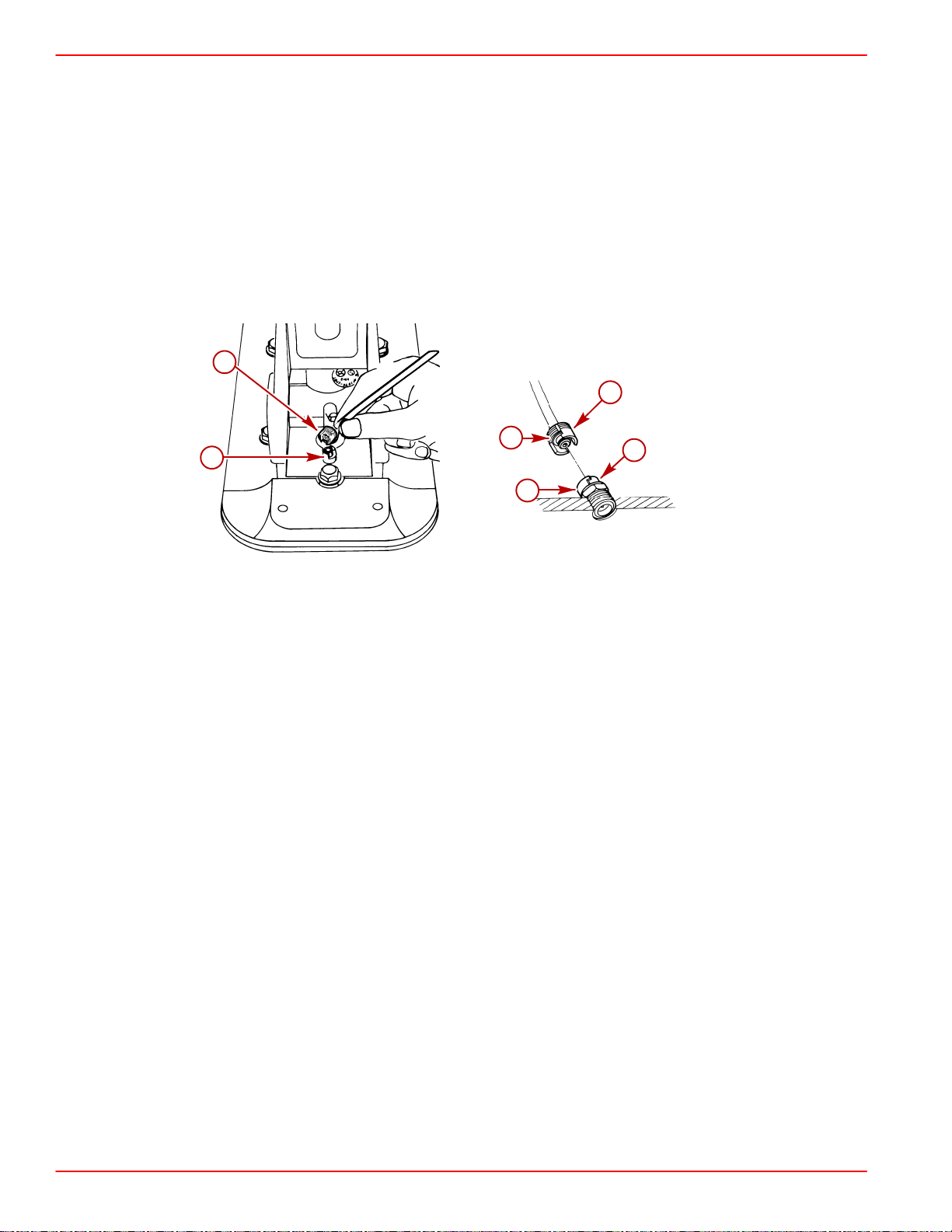
REMOVAL, INSTALLATION AND ADJUSTMENTS SERVICE MANUAL NUMBER 14
Sterndrive Unit Removal
1. Move remote control shift lever into the FORWARD gear position on standard rotation
gear cases, or REVERSE on counter rotation gear cases.
2. Press trailer button on control handle to raise drive unit to trailer position / full-up position.
3. Raise the drive unit to gain access to area between gimbal housing and sterndrive
immediately atop the transom end of the anti-ventilation plate.
4. Disconnect speedometer fittings following a. or b. as appropriate:
a. Grasp the top half of the plastic fitting, turn counterclockwise and pull up to
disengage locking device.
a
a
c
b
b
75580
1997-1/2 and Earlier Model Speedometer Connector
a-Speedometer Connector, Male End
b-Speedometer Connector, Female End
c-Alignment Slots
c
70025
Page 2A-2 90-818177--3 APRIL 2001
Page 85
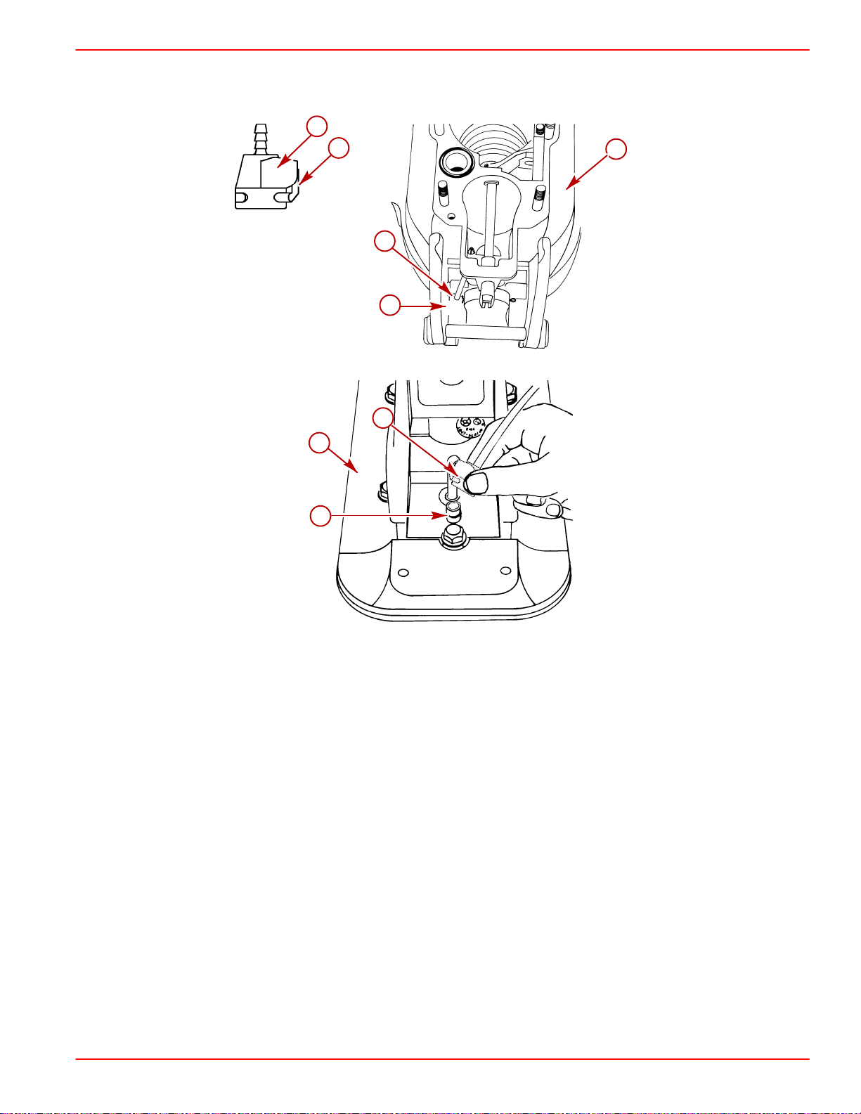
SERVICE MANUAL NUMBER 14
b. Push in on the release button on the female end of the speedometer connector. Pull
to remove.
a
75502
REMOVAL, INSTALLATION AND ADJUSTMENTS
d
b
c
a
75581
a
f
e
75513
1998 and Later Model Speedometer Connector
a-Speedometer Connector, Female End
b-Bell Housing
c-Sta-Strap
d-Release Button
e-Speedometer Connector, Male End
f-Drive Unit
IMPORTANT: When lifting drive with other than hydraulic system, secure the drive
unit with a suitable lifting device so that the drive unit will not fall.
5. Lower drive unit to full IN/DOWN position.
90-818177--3 APRIL 2001 Page 2A-3
Page 86
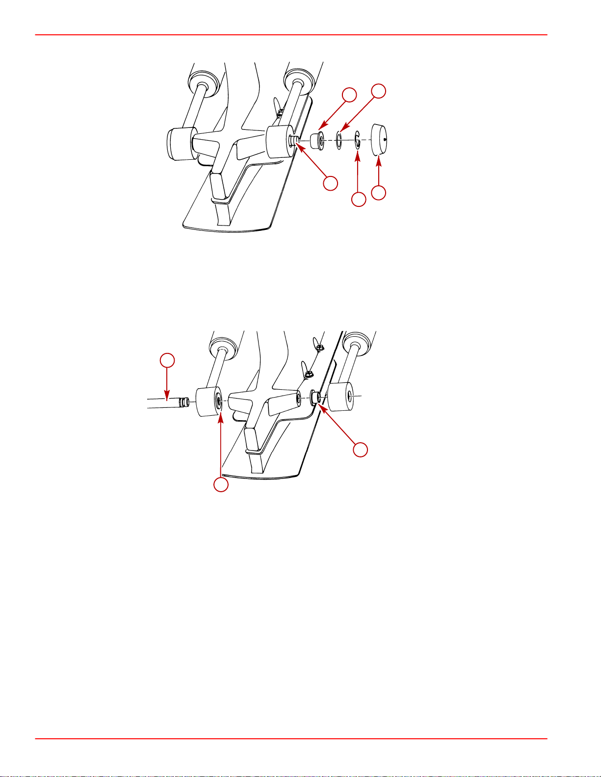
REMOVAL, INSTALLATION AND ADJUSTMENTS SERVICE MANUAL NUMBER 14
6. Remove power trim cylinders (aft end) from drive unit.
a-Aft Anchor Pin
b-Bushings (4)
c-Flat Washers (2)
d-E-ring Clips (2)
e-Plastic Caps (2)
a
b
c
a
e
d
70027
b
a-Aft Anchor Pin
b-Bushings
b
70026
Page 2A-4 90-818177--3 APRIL 2001
Page 87
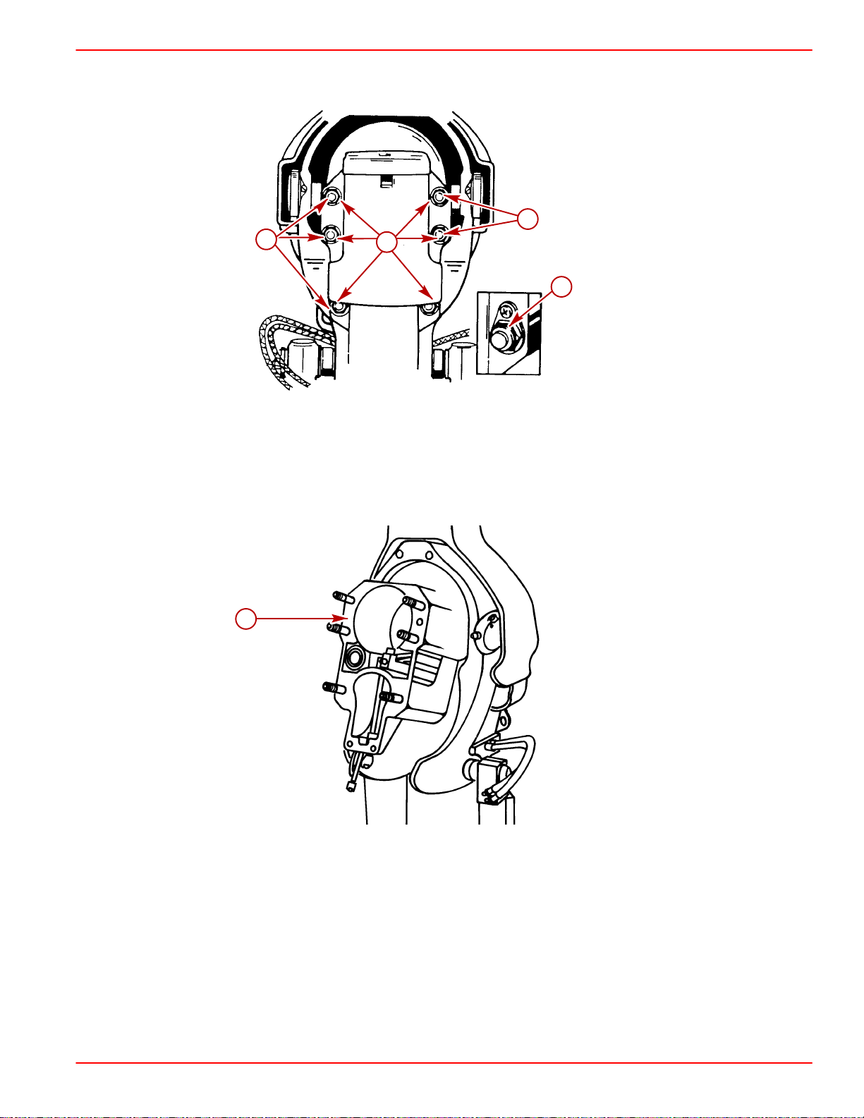
SERVICE MANUAL NUMBER 14
7. Remove the 6 locknuts and 5 washers that hold the drive unit to the transom unit and
remove sterndrive unit.
a-Locknuts (6)
b-Washers (5)
c-Ground Plate
REMOVAL, INSTALLATION AND ADJUSTMENTS
b
b
a
c
22062
8. Remove bell housing gasket.
a
a-Bell Housing Gasket
70085
90-818177--3 APRIL 2001 Page 2A-5
Page 88

REMOVAL, INSTALLATION AND ADJUSTMENTS SERVICE MANUAL NUMBER 14
Sterndrive Unit Installation
1. Install and align engine. Refer to appropriate engine service manual.
IMPORTANT: Rubber gasket must be properly positioned and glued in bell housing
bore before installing drive unit or water may leak into boat.
2. Ensure that rubber gasket and water passage O-ring are properly positioned in bell
housing.
3. Coat entire stud and threads with 2-4-C Marine Lubricant with Teflon.
c
a
75684
b
a-Rubber Gasket
b-Water Passage O-ring
c-Studs
4. Coat drive unit pilot, U-joint shaft O-rings and U-joint shaft splines with Engine
Coupler Spline Grease.
a
70022
b
c
70114
a-Drive Unit Pilot
b-U-joint Shaft O-rings
c-U-joint Shaft Splines
5. Snap the Shift Slide Stabilizer Tool onto stud directly below shift slide and position as
shown.
Page 2A-6 90-818177--3 APRIL 2001
Page 89
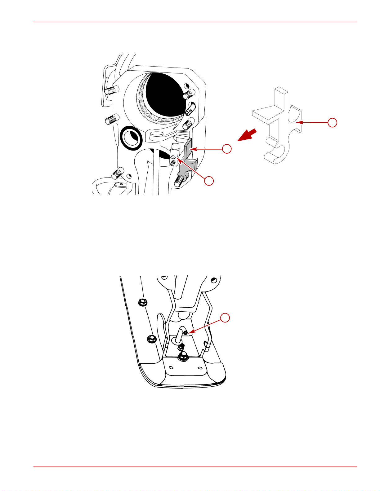
SERVICE MANUAL NUMBER 14
6. Position bell housing shift slide so that slot in intermediate shaft coupler is positioned
straight fore and aft. Do this by placing remote control shift lever in: FORWARD gear
WOT position for RH drive or REVERSE gear position for LH drive unit.
REMOVAL, INSTALLATION AND ADJUSTMENTS
75684
a
a
75199
b
75198
a-Shift Shaft Slide Stabilizer Tool
b-Shift Slide
IMPORTANT: Shift slide assembly is free to rotate on core wire. Therefore, be careful
that shift slide remains in upright position and is properly engaged with shift shaft
lever while installing drive unit.
7. Position drive unit shift shaft so that is straight forward by turning shift shaft clockwise
while simultaneously turning propeller shaft counterclockwise.
a
70033
a-Drive Unit Shift Shaft Coupler
IMPORTANT: Be sure to install RH or LH drive unit on the appropriate transom
assembly when making dual engine installations. The LH rotation drive unit can be
identified by the decal on the back side of the upper drive shaft housing, which
states: “Alpha One - Counter Rotation” or has an L on the propshaft
90-818177--3 APRIL 2001 Page 2A-7
Page 90

REMOVAL, INSTALLATION AND ADJUSTMENTS SERVICE MANUAL NUMBER 14
8. Place gasket on bell housing.
a
70048
Without Gear Lube Monitor
(Shown Without Shift Slide Stabilizer Tool For Visual Clarity)
a-Gasket
NOTE: If equipped with Gear Lube Monitor BE SURE to install the gasket with the hole for
oil passage.
a
b
With Gear Lube Monitor
(Shown Without Shift Slide Stabilizer Tool For Visual Clarity)
a-Gasket
b-Oil Passage Hole
9. Install sterndrive unit:
a. Position trim cylinder straight back (over top of acceleration plate). Be careful not to
scratch acceleration plate or trim cylinders.
70048
b. Guide U-joint shaft through gimbal bearing and into engine coupler while
simultaneously guiding shift slide into drive shaft housing. Make sure shift slide
remains upright and engaged with bell housing shift shaft lever.
c. After the U-joint shaft has begun to enter the engine coupler, remove the Shift Slide
Stabilizer Tool.
Page 2A-8 90-818177--3 APRIL 2001
Page 91

SERVICE MANUAL NUMBER 14
d. Ensure that the stud is thoroughly coated with Quicksilver 2-4-C Marine Lubricant
IMPORT ANT: If drive unit will not slide all the way into bell housing, ensure shift shaft
couplers are positioned properly and all O-rings are greased. Do not force drive unit
into position.
e. If necessary, rotate propeller shaft counterclockwise slightly to help align U-joint
10. Secure drive unit to bell housings using fasteners as shown. Torque to 50 lb-ft (68 NSm).
REMOVAL, INSTALLATION AND ADJUSTMENTS
with Teflon.
shaft splines with engine coupler splines. Then slide drive unit into bell housing.
a
b
22062
a-Locknut and Flat Washers
b-Locknut and Continuity Circuit Washer (No Flat Washer at this Location)
11. Return remote control shift lever to the neutral position.
12. Install trim cylinders on aft end of drive unit with hardware as shown. Coat all
components, except plastic caps, with Quicksilver Special Lube 101 upon installation.
Push-fit plastic caps onto ends of aft anchor pins.
a. Insert one bushing in each inboard hole of both trim cylinders.
b. Align the bores of the trim cylinders with that of the drive unit.
c. Insert the aft anchor pin through one of the trim cylinders, the drive unit bore and then
the other trim cylinder until it protrudes equally on both sides of the unit.
90-818177--3 APRIL 2001 Page 2A-9
Page 92

REMOVAL, INSTALLATION AND ADJUSTMENTS SERVICE MANUAL NUMBER 14
NOTE: Distance between the trim cylinders and the drive unit anchor pin bore is
exaggerated for visual clarity.
a
b
b
70026
a-Aft Anchor Pin
b-Bushings
d. Install the two remaining bushings onto the aft anchor pin ends and fit into bore of
trim cylinders.
e. Install the flat washers.
f. Install the E-ring clips.
NOTE: The inboard grooves of the aft anchor pin are for E-ring clips, and wider, outboard
grooves are for securing plastic caps.
c
e
a
b
d
70027
a-Aft Anchor Pin
b-Bushings
c-Flat Washers (2)
d-E-ring Clips (2)
e-Plastic Caps (2)
13. Raise drive to gain access to area between gimbal housing and sterndrive, immediately
atop the transom end of the anti-ventilation plate.
14. Connect speedometer fittings following a. or b. as appropriate:
Page 2A-10 90-818177--3 APRIL 2001
Page 93

SERVICE MANUAL NUMBER 14
a. Align the plastic fittings, push down and turn clockwise to engage locking device.
REMOVAL, INSTALLATION AND ADJUSTMENTS
a
c
b
75580
1997-1/2 and Earlier Model Speedometer Connector
a-Male End Of Speedometer Fitting
b-Female End Of Speedometer Fitting
c-Alignment Slots
b
a
c
70025
90-818177--3 APRIL 2001 Page 2A-11
Page 94

REMOVAL, INSTALLATION AND ADJUSTMENTS SERVICE MANUAL NUMBER 14
b. Push the release button and slide the female portion of the speedometer connector
over the male portion.
b
c
a
75581
a-Speedometer Connector, Female End
b-Bell Housing
c-Sta-Strap
b
c
a
1998 and Later Model Speedometer Connector
a-Speedometer Connector, Male End
b-Speedometer Connector, Female End
c-Gear Housing
75513
Page 2A-12 90-818177--3 APRIL 2001
Page 95
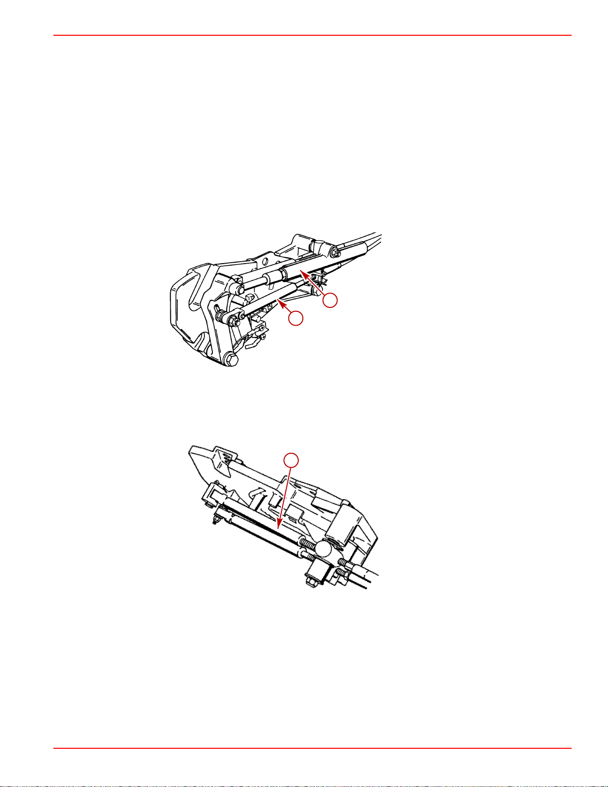
SERVICE MANUAL NUMBER 14
REMOVAL, INSTALLATION AND ADJUSTMENTS
Remote Control Shift Cable Adjustment (Drive Unit Installed)
NOTE: The illustrations on the following pages show models that have a shift plate that is
mounted on the exhaust elbow. The shift mechanism components on the 3.0L model are
located on the top of the valve cover or on the starboard harness bracket. The procedure
for making the adjustments is the same.
IMPORT ANT: Shift cable adjustment for a right hand (RH) rotation drive unit is different than the procedure for adjusting a left hand (LH) rotation drive unit. Be sure to
refer to the appropriate procedure when performing the following steps.
IMPORTANT: Drive unit must be installed.
IMPORTANT: DO NOT run engine.
1. Remove remote control shift cable and shift assist assembly (if installed).
a
b
With Shift Assist Assembly
a-Shift Assist Assembly
b-Remote Control Shift Cable
a
50308
50310
Without Shift Assist Assembly
a-Remote Control Shift Cable
90-818177--3 APRIL 2001 Page 2A-13
Page 96
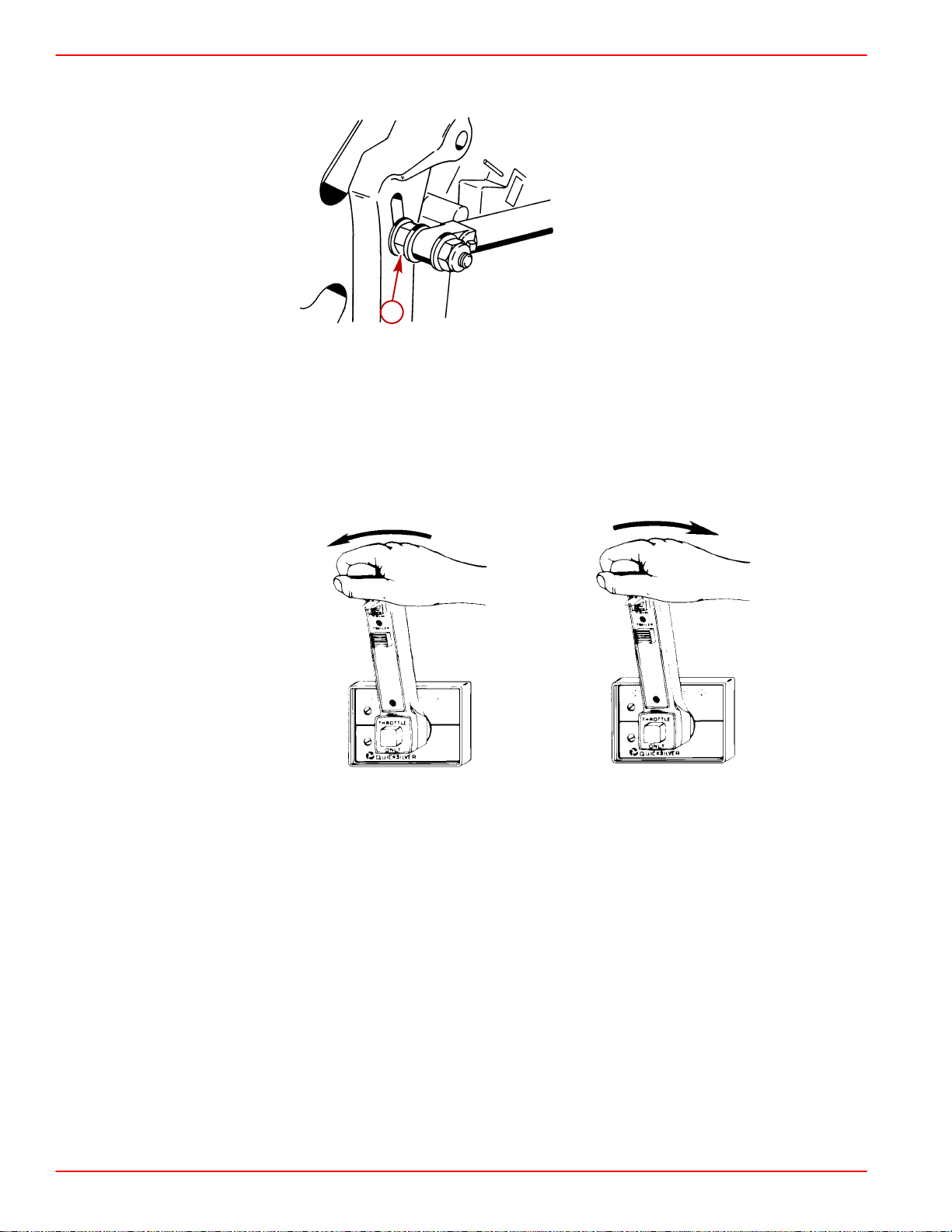
REMOVAL, INSTALLATION AND ADJUSTMENTS SERVICE MANUAL NUMBER 14
2. Ensure shift lever adjustable stud is located in the slot at the end closest to the shift lever
pivot point. If necessary, loosen stud and align stud in the slot, then retighten stud.
50309
a
a-Adjustable Stud
3. Shift remote control as stated in a. or b.:
a. Right Hand (RH) Rotation Drive Unit - forward gear, past detent, into wide-open-
throttle position.
b. Left Hand (LH) Rotation Drive Unit - reverse gear, past detent, into
wide-open-throttle position.
N
F
(RH)
4. Place drive unit into gear by pushing in on drive unit shift cable, while simultaneously
rotating propeller shaft counterclockwise until shaft stops, to ensure full clutch engagement. Maintain a light pressure on the drive unit shift cable to hold it at the end of its travel
(this removes all slack from the cable).
R
R
(LH)
Page 2A-14 90-818177--3 APRIL 2001
Page 97
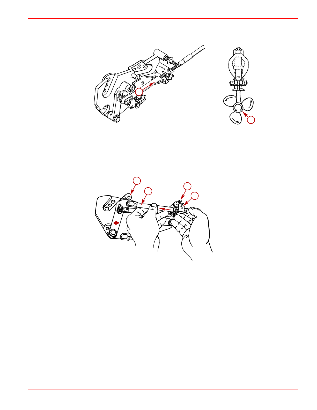
SERVICE MANUAL NUMBER 14
IMPORTANT: Do not use excessive force when holding pressure on the drive unit
shift cable. Excessive force would be indicated by movement of the V-notch of the
actuator lever assembly.
REMOVAL, INSTALLATION AND ADJUSTMENTS
a
b
22266
a-Drive Unit Shift Cable - Push In
b-Propeller Shaft - Rotate Counterclockwise
5. Lightly pull on remote control shift cable end guide (to remove slack from remote control
and cable) and adjust brass barrel as necessary to align attaching points with shift lever
clevis pin hole and stud. Be sure to maintain light pressure on drive unit shift cable.
c
d
a
b
50309
a-End Guide
b-Brass Barrel
c-Shift Lever Clevis Pin Hole
d-Stud
90-818177--3 APRIL 2001 Page 2A-15
Page 98
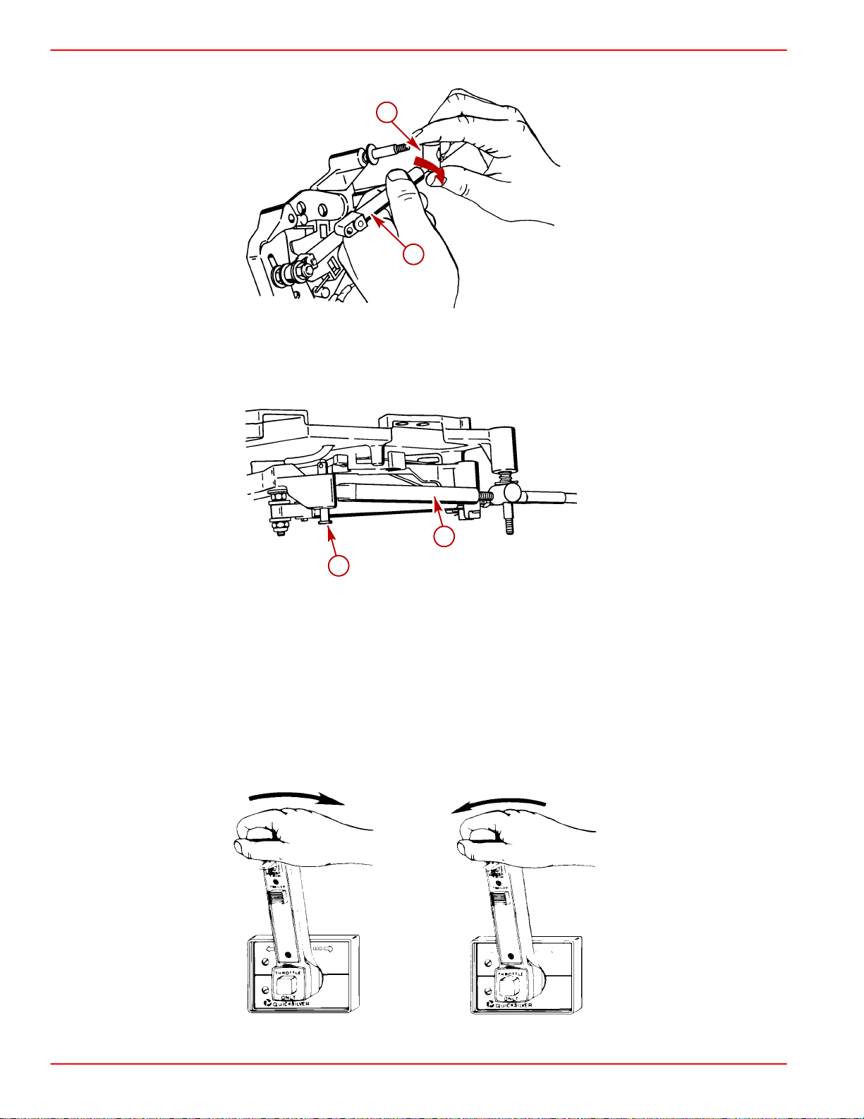
REMOVAL, INSTALLATION AND ADJUSTMENTS SERVICE MANUAL NUMBER 14
6. After cable has been aligned, turn brass barrel 4 turns away from cable end guide.
b
a
50308
e-End Guide
f-Brass Barrel
7. Temporarily install remote control shift cable on stud and install clevis pin.
a
b
a-Remote Control Shift Cable
b-Clevis Pin
8. Shift remote control as stated in a. or b. :
a. Right Hand (RH) Rotation Drive Unit - reverse gear, past detent, into wide-open-
throttle position.
b. Left Hand (LH) Rotation Drive Unit - forward gear, past detent, into wide-open-
throttle position.
(RH)
(LH)
N
R
F
R
50308
Page 2A-16 90-818177--3 APRIL 2001
Page 99
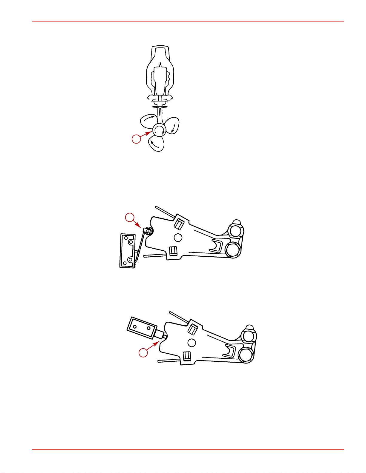
SERVICE MANUAL NUMBER 14
9. Simultaneously rotate propeller shaft clockwise until shaft stops to ensure full clutch en-
gagement.
REMOVAL, INSTALLATION AND ADJUSTMENTS
a
a-Propeller Shaft - Rotate Clockwise
10. Perform a. or b. as appropriate:
a. On Models with Earlier Type Switch: check shift cutout switch lever position. Roll-
er must be centered.
a
a-Shift Cutout Switch Roller
b. On Models with Later Type Switch: check shift cutout switch plunger position. Pin
must be centered.
22267
22058
a
75128
a-Shift Cutout Switch Plunger
11. If roller or plunger pin is not centered:
a. Ensure adjustable stud is at bottom of slot in shift lever.
b. Check remote control for proper shift cable output [3 in. (76 mm)
c. If a and b are correct, ensure drive unit shift cable is not crushed or kinked. (If drive
unit shift cable is binding, the shift cutout switch roller or plunger pin will move off
center when shifting “into” and “out of” forward and reverse).
90-818177--3 APRIL 2001 Page 2A-17
± 1/8 in. (3 mm)].
Page 100

REMOVAL, INSTALLATION AND ADJUSTMENTS SERVICE MANUAL NUMBER 14
NOTE: If shift cable was damaged during installation, install new shift cable assembly , then
repeat shift cable adjustment procedure.
CAUTION
Improper installation of the shift assist assembly could result in damage or malfunction to the shift control box.
For Commander 3000 Controls, if shift assist assembly attaching points do not align, verify
controller is in the neutral position. Remove the shift cable and reposition the adjustment
barrel as required to allow the shift assembly to be installed with no effort.
For ALL other controls, if shift assist assembly attaching points do not align, push in or
pull out on end of shift assist assembly to install. Do not attempt to readjust shift cable.
Page 2A-18 90-818177--3 APRIL 2001
 Loading...