

Page 1
Identification Record
41269
a
b
Please record the following information:
The serial numbers are the manufacturer’s keys to numerous engineering details
that apply to your Cummins MerCruiser Diesel product. When contacting Cummins
MerCruiser Diesel (CMD) about service, always specify model and serial numbers.
Refer to the engine operation and maintenance manual available from the engine
manufacturer for the location of the engine data tag, which contains the engine serial
number and model number.
90-866938081 509
*866938081*
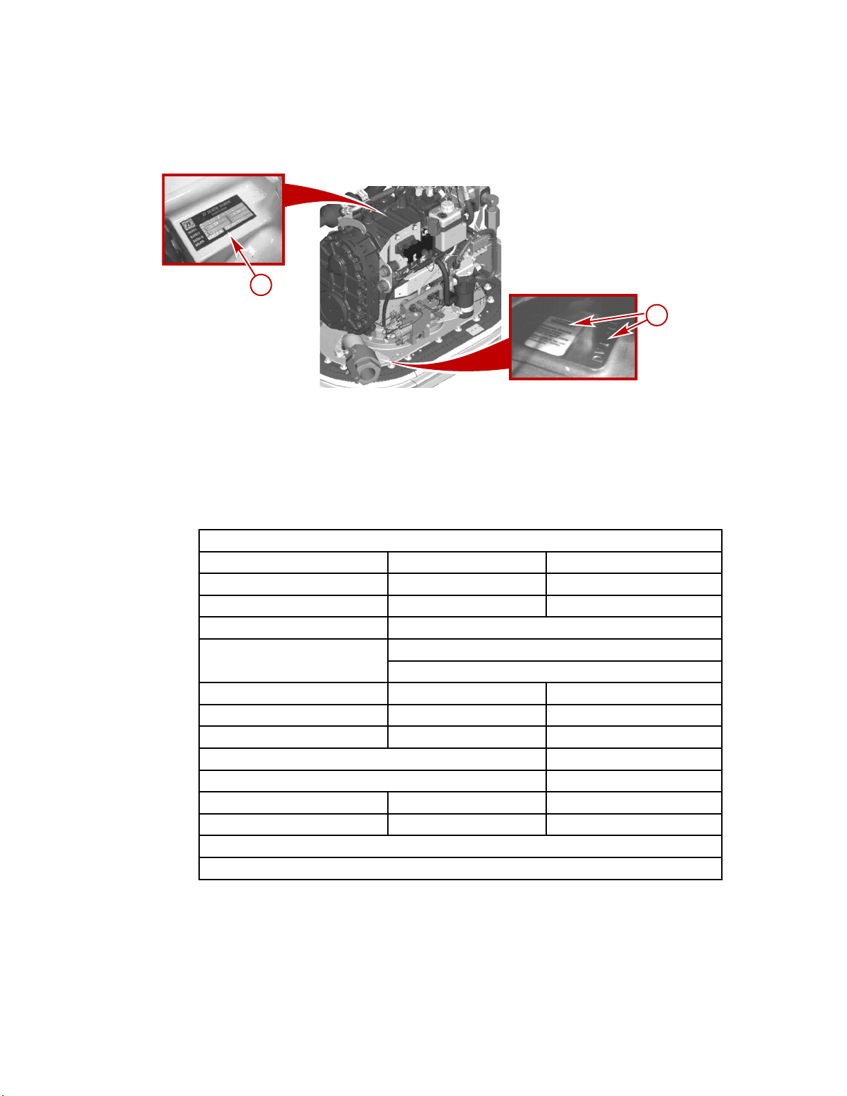
Drive serial number locations
a - Transmission serial number plate b - Drive serial number decal and
stamping
Please record the following information:
Drive Serial Numbers Zeus Drive Serial Number Transmission Serial Number
Port
Starboard
Engine Model and Horsepower Engine Serial Number
/
Propeller Information Propeller Part Number Pitch
Front ‑
Rear ‑
Boat Hull Identification Number (HIN) Purchase Date
Boat Manufacturer Boat Model Boat Length
.
Exhaust Gas Emissions Certificate Number (Europe Only)
The description and specifications contained herein were in effect at the time this
guide was approved for printing. CMD, whose policies are based on continuous
improvement, reserves the right to discontinue models at any time or to change
specifications or designs without notice and without incurring obligation.
Mercury Marine, Fond du Lac, Wisconsin, U.S.A. Printed in U.S.A.
©2009, Mercury Marine
Port
Starboard
/
/
© 2009 Mercury Marine CMD Zeus 3000 Series Pod Drive Models
Page 2
Mercury, Mercury Marine, MerCruiser, Mercury MerCruiser, Mercury Racing, Mercury
Precision Parts, Mercury Propellers, Mariner, Quicksilver, #1 On The Water, Alpha,
Bravo, Bravo Two, Pro Max, OptiMax, Sport‑Jet, K‑Planes, MerCathode, RideGuide,
SmartCraft, Zero Effort, VesselView, Zeus, Axius, Total Command, M with Waves logo,
Mercury with Waves logo, and SmartCraft logo are all trademarks or registered trademarks
of Brunswick Corporation. Mercury Product Protection logo is a registered service mark of
Brunswick Corporation.
Welcome
You have selected one of the finest marine power packages available. It incorporates
numerous design features to ensure operating ease and durability.
With proper care and maintenance, you will thoroughly enjoy using this product for many
boating seasons. To ensure maximum performance and carefree use, we ask that you
thoroughly read this manual, which contains specific instructions for using and maintaining
your product. We suggest that this manual remain with the product for reference whenever
you are on the water.
Thank you for purchasing one of our Cummins MerCruiser Diesel products. We sincerely
hope your boating will be pleasant.
Cummins MerCruiser Diesel
Warranty Message
The product you have purchased comes with a limited warranty from Cummins
MerCruiser Diesel; the terms of the warranty are set forth in the Warranty Sections of this
manual. The warranty statement contains a description of what is covered, what is not
covered, the duration of coverage, how to best obtain warranty coverage, important
disclaimers and limitations of damages, and other related information. Please review
this important information.
Read This Manual Thoroughly
IMPORTANT: If you do not understand any portion of this manual, contact your dealer for
a demonstration of the actual starting and operating procedures.
Notice
Throughout this publication, and on your power package, dangers, warnings, cautions, and
notices, accompanied by the International Hazard Symbol
installer and user to special instructions concerning a particular service or operation that
may be hazardous if performed incorrectly or carelessly. Observe them carefully.
These Safety Alerts alone cannot eliminate the hazards that they signal. Strict compliance
with these special instructions while performing the service, plus common sense
operation, are major accident prevention measures.
Indicates a hazardous situation which, if not avoided, will result in death or serious
injury.
Indicates a hazardous situation which, if not avoided, could result in death or serious
injury.
DANGER
!
WARNING
!
!
, may be used to alert the
Page 3
CAUTION
!
Indicates a hazardous situation which, if not avoided, could result in minor or moderate
injury.
NOTICE
Indicates a situation which, if not avoided, could result in engine or major component
failure.
IMPORTANT: Identifies information essential to the successful completion of the task.
NOTE: Indicates information that helps in the understanding of a particular step or action.
WARNING
!
The operator (driver) is responsible for the correct and safe operation of the boat, the
equipment aboard and the safety of all occupants aboard. We strongly recommend that
the operator read this Operation, Maintenance and Warranty Manual and thoroughly
understand the operational instructions for the power package and all related accessories
before the boat is used.
WARNING
!
The engine exhaust from this product contains chemicals known to the state of California
to cause cancer, birth defects or other reproductive harm.
Page 4

Page 5

TABLE OF CONTENTS
Section 1 - Limited Warranty
Warranty Information...............................................2
Warranty Registration—United States and
Canada.............................................................2
Warranty Registration—Outside the United
States and Canada...........................................2
High Output Recreational Use World‑Wide
Limited Warranty..............................................3
Section 2 - Getting to Know Your Power Package
General Information...............................................14
Models Covered.............................................14
Drive Serial Number and Decal Placement....14
Features and Controls...........................................14
E‑Stop (Emergency Stop) Switch, If
Equipped........................................................14
Instrumentation...............................................15
VesselView...................................................15
SmartCraft Speedometer and Tachometer
Digital Gauges (If Equipped)........................15
System Link Digital Gauges (If Equipped)...16
Electronic Helm Steering................................17
Intermittent Commercial Use World‑Wide
Limited Warranty..............................................7
Zeus Drive Limited Warranty Against Corrosion
(Worldwide)....................................................10
Emission Warranty.........................................11
Transfer Of Warranty......................................11
Dual‑Handle Electronic Remote Control (ERC)—
Features and Operation.................................17
Operation.....................................................17
Basic Joystick Operation................................18
Electrical System Overload Protection...........18
Vessel Interface Panel (VIP) Overload
Protection.....................................................19
Overload Protection for the DC Voltage
Regulator System, If Equipped ...................19
Overload Protection for Other Circuits.........20
Galvanic Isolator and Monitor.........................20
Section 3 - On the Water
Safe Boating Suggestions.....................................25
Be Alert to Carbon Monoxide Poisoning........26
Good Ventilation...........................................26
Poor Ventilation ...........................................27
Basic Boat Operation.............................................27
Freezing Temperature and Cold Weather
Operation........................................................27
Drain Plug and Bilge Pump............................28
Protecting People in the Water.......................28
While the Boat is Moving..............................28
While the Boat is Stationary.........................29
Wave and Wake Jumping..............................29
Impact with Underwater Hazards...................29
Zeus Drive Impact Protection.........................30
Zeus Drive Alignment.....................................31
Conditions Affecting Boat Operation.....................31
Weight Distribution (Passengers and Gear)
Inside the Boat...............................................31
Bottom Of Boat...............................................31
Cavitation.......................................................31
Ventilation.......................................................31
Propeller Selection.........................................31
Getting Started......................................................32
Break‑In Period (New or With Replacement
Gears)............................................................32
DC Voltage Regulator Switch, If Equipped.....32
Starting and Stopping the Engines.................33
Normal Starting............................................33
Normal Stopping..........................................35
Starting an Engine Using the VIP SmartStart
Switch...........................................................35
Stopping the Engine Using the VIP SmartStart
Switch...........................................................37
Traditional Maneuvering with Steering and
Thrust.............................................................38
To Maneuver the Boat in Forward................38
To Steer the Boat in Tight Turns at Low
Speeds.........................................................38
To Spin the Boat on its Axis at Low Speeds 39
Maneuvering with the Joystick.......................39
90-866938081 MAY 2009 Page i
Page 6

Trim Tabs......................................................43
Automatic Control....................................... 43
Manual Control............................................44
Using Trim Tab Offset.................................44
Special Digital Throttle and Shift (DTS)
Features........................................................45
Troll and Throttle Response........................46
Dock............................................................47
Throttle Only............................................... 47
Single Lever (1 Lever) Operation................48
Synchronizing the Engines......................... 49
Cruise Control............................................... 49
Helm Transfer.......................................................50
Requesting Helm Transfer............................ 50
Helm Transfer and Precision Pilot.................51
Precision Pilot.......................................................51
Precision Pilot Trackpad Features................ 51
General Information.................................... 51
Standby.......................................................51
Standby and Active Lights.......................... 52
Power Icon..................................................53
Skyhook (If Equipped)...................................53
Engaging (Activating) Skyhook...................55
The Skyhook Screen in VesselView........... 57
Disengaging (Deactivating) Skyhook..........57
Auto Heading................................................ 58
Engaging Auto Heading..............................58
Course Adjustment Using the Turn Buttons or
Joystick....................................................... 59
To Resume a Heading ...............................60
Disengaging Auto Heading......................... 60
Response Button...........................................62
Track Waypoint............................................. 62
Engaging Track Waypoint Mode.................63
Disengaging Track Waypoint Mode............64
Turn Buttons or Joystick in Track Waypoint
Mode...........................................................64
Auto Heading Button in Track Waypoint
Mode ..........................................................64
Acknowledging a Turn During a Waypoint
Arrival..........................................................64
Waypoint Sequence....................................66
Contingent Operations......................................... 68
Steering—Emergency Alternative Method....68
Port Engine Only Operation.......................... 69
Gear Engagement—Emergency Procedure. 69
Steering and Trim—Manual Override........... 70
Procedure for a Stuck Steering Control
Valve...........................................................72
Procedure for a Stuck Trim Tab Control
Valve...........................................................73
End of First Season Checkup...............................73
Section 4 - Specifications
Drive Gear Lubricant............................................ 76
Transmission........................................................76
Steering Actuator and Trim Oil.............................76
Section 5 - Maintenance
Product Responsibilities.......................................80
Owner and Operator Responsibilities........... 80
Dealer Responsibilities..................................80
Do‑It‑Yourself Maintenance Suggestions......80
Inspection......................................................81
Drive Service Point Locations.............................. 82
Starboard...................................................... 82
Port................................................................82
Top................................................................83
Drop Box....................................................... 83
Maintenance Schedules.......................................83
Application.....................................................83
Routine Maintenance.................................... 84
Scheduled Maintenance................................84
Maintenance Log...........................................85
Drive Cover, If Equipped...................................... 87
Approved Paints...................................................76
Approved Lubricants............................................ 76
Removing the Drive Cover............................87
Cleaning and Inspecting the Drive Cover......87
Installing the Drive Cover..............................88
Drive Gear Lube...................................................90
Drive Gear Lubrication.................................. 90
Checking....................................................... 91
Filling.............................................................93
Changing.......................................................94
With the Boat in the Water..........................94
With the Boat Out of the Water...................97
Steering Actuator and Trim—Hydraulic Oil.......... 99
Checking....................................................... 99
Filling...........................................................100
Changing.....................................................102
Transmission Oil (Fluid) and Filter.....................102
Checking.....................................................102
Page ii 90-866938081 MAY 2009
Page 7

Filling............................................................104
Changing......................................................106
Seawater System................................................110
Draining the Seawater System.....................110
Boat out of the Water.................................110
Boat in the water........................................112
Checking the Seawater Pickup on the Drive 115
Seawater Strainer.........................................116
Flushing the Seawater System.....................116
Battery.................................................................116
Gauges................................................................116
Checking Gauges.........................................116
Cleaning Gauges..........................................117
Electrical System.................................................117
Cooling System and Exhaust System.................117
Lubrication...........................................................117
Driveshaft Slip‑Joint ....................................117
Driveshaft U‑Joints ......................................119
Propeller Shaft..............................................121
Corrosion and Corrosion Protection....................122
The Causes of Corrosion.............................122
Corrosion Protection.....................................122
Anodes and MerCathode System ...............123
Reference Electrode Wire of the MerCathode
System.........................................................124
MerCathode Anode......................................124
Checking....................................................124
Replacing...................................................124
MerCathode System Testing........................124
Trim Tab Anode............................................125
Checking....................................................125
Replacing...................................................125
Continuity Circuits........................................126
Inhibiting Corrosion......................................127
Painting the Boat..........................................127
Propellers............................................................128
Propeller Removal........................................128
Propeller Repair...........................................129
Propeller Installation.....................................130
Section 6 - Storage
Storage Descriptions...........................................134
Drive Storage.......................................................134
Cold Weather (Freezing Temperature)
Storage.........................................................134
Seasonal and Extended Storage
Instructions...................................................135
Section 7 - Troubleshooting
Diagnosing Electronically Controlled Fuel System
Problems.............................................................138
Electrical Connections.........................................138
Troubleshooting Charts.......................................138
Troubleshooting Engine Related Problems..138
Check VesselView First................................138
Poor Performance........................................139
Joystick.........................................................139
Engine Storage.............................................135
Battery Storage....................................................135
Recommissioning................................................135
Engine..........................................................135
Drive.............................................................136
Power Package............................................136
Electronic Remote Controls..........................139
Steering System...........................................140
Trim Tabs.....................................................141
Boat Response Changes.............................141
Battery Will Not Charge................................141
Gauges and Instrumentation........................142
Galvanic Isolator...........................................142
Section 8 - Customer Assistance Information
Owner Service Assistance...................................144
Marine Repair Logistics................................144
Local Repair Service....................................144
Service Away From Home............................144
Stolen Power Package.................................144
Attention Required After Submersion...........144
90-866938081 MAY 2009 Page iii
Replacement Service Parts..........................144
Parts and Accessories Inquiries...................145
Resolving a Problem....................................145
Page 8

Customer Service Literature...............................145
English Language..........................................145
Other Languages...........................................146
Andre sprog...................................................146
Andere talen..................................................146
Muut kielet.....................................................146
Autres langues...............................................146
Andere Sprachen...........................................146
Altre lingue.....................................................146
Section 9 - Pre-Delivery Information
Andre språk...................................................146
Outros Idiomas..............................................147
Otros idiomas.................................................147
Andra språk...................................................147
Allej glþssej....................................................147
Ordering Literature.............................................147
United States and Canada............................147
Outside the United States and Canada.........147
Pre‑Delivery Information.....................................150
Dealer Pre‑Delivery Checklist for Zeus Products
(Before Delivery to the Customer)......................150
Skyhook (If Equipped)...................................150
Before Starting—Key Off...............................151
Before Starting—Key On...............................151
Engines Running at the Dock........................151
Sea Trial........................................................152
After On Water Test.......................................152
Skyhook (If Equipped)...................................152
Page iv 90-866938081 MAY 2009
Page 9

Section 1 - Limited Warranty
Section 1 - Limited Warranty
Table of Contents
Warranty Information............................................ 2
Warranty Registration—United States and
Canada............................................................2
Warranty Registration—Outside the United
States and Canada.........................................2
High Output Recreational Use World‑Wide
Limited Warranty.............................................3
1
Intermittent Commercial Use World‑Wide
Limited Warranty.............................................7
Zeus Drive Limited Warranty Against Corrosion
(Worldwide)...................................................10
Emission Warranty........................................11
Transfer Of Warranty....................................11
90-866938081 MAY 2009 Page 1
Page 10

Section 1 - Limited Warranty
Warranty Information
Warranty Registration—United States and Canada
The CMD warranty registration center will coordinate warranty registration for both
CMD/Cummins and Mercury Marine products, only one Warranty Registration Form
is required to be filed for each engine/drive system.
1. To ensure that your warranty coverage begins promptly, your selling dealer should fill
out the Warranty Registration Card completely and mail it to the factory immediately
upon sale of the new product.
2. The Warranty Registration Card identifies the name and address of the original
purchaser, product model and serial number(s), date of sale, type of use and selling
dealer’s code, name, and address. The dealer also certifies that you are the original
purchaser and user of the product. A temporary Owner Warranty Registration Card will
be presented to you when you purchase the product.
3. Upon receipt of the Warranty Registration Card at the factory, you will be sent an owner
resource guide that includes your warranty registration confirmation. If you do not
receive your owner resource guide within 60 days from date of new product sale, please
contact your selling dealer.
4. Because of your selling dealer’s ongoing interest in your satisfaction, the product
should be returned to him for warranty service.
5. The product warranty is not effective until the product is registered at the factory.
NOTE: Registration lists must be maintained by the factory and dealer on marine products
sold in the United States in the event that a safety recall notification under the Federal Boat
Safety Act is required.
6. You may change your registration address at any time, including at time of warranty
claim, by calling CMD or sending a letter or fax with your name, old address, new
address, and engine serial number to CMD's warranty registration department. Your
dealer can also process this change of information.
United States customers or dealers may contact:
Cummins MerCruiser Diesel LLC, Inc.
Attn: Warranty Registration Department
4500 Leeds Avenue - Suite 301
Charleston, South Carolina 29405-9987
1-800-668-0407
Fax Fax 843-745-1616
Warranty Registration—Outside the United States and Canada
1. It is important that your selling dealer fills out the Warranty Registration Card completely
and mails it to the Cummins MerCruiser Diesel Distributor or Cummins MerCruiser
Diesel Authorized Dealer responsible for administering the warranty registration and
claim program for your area.
2. The Warranty Registration Card identifies your name and address, product model and
serial numbers, date of sale, type of use and the selling distributor's and dealer's code
number, name and address. The distributor or dealer also certifies that you are the
original purchaser and user of the product.
Page 2 90-866938081 MAY 2009
Page 11

Section 1 - Limited Warranty
3. A copy of the Warranty Registration Card, designated as the Purchaser's Copy, MUST
be given to you immediately after the card has been completely filled out by the selling
distributor or dealer. This card represents your factory registration identification, and
should be retained by you for future use when required. Should you ever require
warranty service on this product, your dealer may ask you for the Warranty Registration
Card to verify date of purchase and to use the information on the card to prepare the
warranty claim forms.
4. In some countries, the Cummins MerCruiser Diesel Distributor or Cummins MerCruiser
Diesel Authorized Dealer will receive the Factory Copy of the Warranty Registration
Card from your distributor or dealer. If you receive a plastic Warranty Registration
Card, you may discard the Purchaser's Copy that you received from the distributor or
dealer when you purchased the product. Ask your distributor or dealer if this plastic
card program applies to you. Center will issue you a permanent (plastic) Warranty
Registration Card within 30 days after
5. For further information concerning the Warranty Registration Card and its relationship
to Warranty Claim processing, refer to the International Warranty. See Table of
Contents. IMPORTANT: Registration lists must be maintained by the factory and dealer
in some countries by law. It is our desire to have ALL products registered at the factory
should it ever be necessary to contact you. Make sure your Cummins MerCruiser Diesel
Distributor or Cummins MerCruiser Diesel Authorized Dealer fills out the warranty
registration card immediately and sends the factory copy to the Marine Power
International Service Center for your area.
High Output Recreational Use World‑Wide Limited Warranty
Engines and Drive Systems Included in this Coverage
Marine Propulsion
Zeus 3000 Series Pod Drive
Products Warranted
This limited warranty applies to new Engines and Drive Systems sold by Cummins MerCruiser Diesel LLC.
Inc., herein after "CMD", that are branded as Cummins MerCruiser Diesel products and used in Marine
applications anywhere in the world where CMD approved service is available1. and delivered to the first user
on or after September 1, 2007. This limited warranty excludes all Engines branded and sold as Cummins Marine
Diesel products. The ’Product’ consists of a new CMD Engine and Drive System, as well as accessories, which
are approved and supplied by CMD and Cummins, and which are either installed by CMD or a CMD authorized
distributor. These Products have the following designation:
High Output Rating
Intended for use in variable load applications where full power is limited to one (1) hour out of every eight (8)
hours of operation. Reduced power operation must be at or below cruise speed. Cruise speed is dependent on
the engine Rated Speed (RPM):
Engine Rated Speed (RPM)
2000–2800 RPM 200 RPM
2801–3500 RPM 300 RPM
3501–4500 RPM 400 RPM
This rating is for pleasure (non‑revenue generating) applications that operate 500 hours or less per year.
Cruise Speed
(Reduction from Engine Rated Speed (RPM)
1. Locations in the United States and Canada are listed in the Cummins United States and Canada Sales and Service Directory;
other locations are listed in the Cummins International Sales and Service Directory.
90-866938081 MAY 2009 Page 3
Page 12

Section 1 - Limited Warranty
Base Engine and Drive Limited Warranty
This limited warranty covers any failures of the Product, under normal use and service, which result from a
defect in CMD material or factory workmanship (Warrantable Failure) Underwater impact damage is not a
warrantable failure. Coverage begins with the retail sale of the Engine and Drive by CMD and continues for the
Duration stated in the following table. The Duration commences on either the date of delivery of the Product to
the first user, or the date the unit is first leased, rented or loaned, or when the Product has been operated for
125 hours, whichever occurs first. Commercial use of this product voids the warranty. Commercial use is defined
as any work or employment related use of the product, or any use of the product which generates income, for
any part of the warranty period, even if the product is only occasionally used for such purposes.
Two Year Limited Warranty—Limited Warranty Coverage
Coverage Duration
(whichever occurs
first)
Coverage Category
Base Engine Warranty 24 1000 Yes Yes Yes Yes
Extended Major Components 72 3000 Yes Yes Yes Yes
Extended Major Components Limited Warranty
The Extended Major Components Limited Warranty provision is concurrent with the Base Engine and Drive
Limited Warranty and continues beyond the expiration of the Base Engine and Drive Limited Warranty for an
additional four years or 2000 hours whichever occurs first. The Extended Major Components Limited Warranty
covers Warrantable Failures of the following Engine and Drive parts or castings (Covered parts):
Engine:
Engine Cylinder Block and Head Casting
Engine Camshaft and Crankshaft Forging
Engine Connecting Rod Forging
Engine Gear Train Gears:
—Crankshaft Gear
—Camshaft and Camshaft Idler Gear
—Accessory Drive Gear
—Fuel Pump Gear
Engine Gear Cover Casting
Flywheel Housing Casting
Months Hours Parts Labor
Repair Charge Paid by CMD
Removal and Installation
Labor
Travel
Bushing and bearing failures are NOT covered.
Drive:
Marine Gear Housing
Marine Gear Drop Box Housing
Steering Actuator Housing Casting
Drive Mid‑section Casting
Lower Gear Housing Casting – (Underwater Impact Damage Excluded)
Trim Tab Casting – (Underwater Impact Damage Excluded)
Bearing Carrier Casting – (Underwater Impact Damage Excluded)
Drive Shaft – (Less U‑joints)
Intermediate Shaft – (Underwater Impact Damage Excluded)
Clamp Rings
Steering and Trim Oil Tank
Skeg – (Underwater Impact Damage Excluded)
Page 4 90-866938081 MAY 2009
Page 13

Consumer Products
The warranty on Consumer Products in the United States is a limited warranty. CMD IS NOT RESPONSIBLE
FOR INCIDENTAL OR CONSEQUENTIAL DAMAGES. Any implied warranties applicable to Consumer
Products terminate concurrently with the expiration of the express warranties applicable to the Product. In the
United States, some states do not allow the exclusion of incidental or consequential damages, or limitations on
how long an implied warranty lasts, so the limitations or exclusions herein may not apply to you.
These warranties are made to all Owners in the chain of distribution and Coverage continues to all
subsequent Owners until the end of the periods of Coverage.
CMD Responsibilities
During the Base Engine and Drive Limited Warranty
CMD will pay for all parts and labor needed to repair the damage to the Product resulting from a Warrantable
Failure when performed during normal business hours. All labor costs will be paid in accordance with Cummins
and Mercury Marine's published Standard Repair Time guidelines. When it is necessary for mechanics to make
on‑site warranty repairs, CMD will pay reasonable travel expenses, including meals, mileage and lodging, for
mechanics to travel to and from the repair dock.
CMD will pay for the lubricating oil, antifreeze, filter elements, and other maintenance items that are not reusable
due to the Warrantable Failure.
CMD will pay for reasonable labor costs for Engine and Drive System removal and reinstallation when necessary
to repair a Warrantable Failure.
During the Extended Major Components Limited Warranty
CMD will pay for parts and labor for the repair or, at its option, the replacement of the defective covered part
and any covered part damaged by a warrantable failure of the defective covered part.
Owner Responsibilities
During the Base Engine and Drive Limited Warranty and the Extended Major Components Limited
Warranty
Owner is responsible for the cost of lubricating oil, antifreeze, filter elements, and other maintenance items
replaced during warranty repairs unless such items are not reusable due to the Warrantable Failure.
During the Extended Major Components Limited Warranties
Owner is responsible for the cost of all parts and labor required for the repair except for the defective Covered
Part and any Covered Part damaged by a Warrantable Failure of the defective Covered Part.
Owner is responsible for the operation and maintenance of the Product as specified in the applicable
Cummins, MerCruiser, or CMD Operation and Maintenance Manual. Owner is also responsible for providing
proof that all recommended maintenance has been performed.
Exceeding the operational parameters of the HO rating will void this warranty. The owner of the boat is ultimately
responsible for ensuring the engine and drive system is properly operated and maintained. The warranty will
be void on any Engines and Drives that are misapplied, not maintained properly or misused.
Before the expiration of the applicable warranty, Owner must notify a CMD distributor, authorized dealer, or
other repair location approved by CMD of any Warrantable Failure and make the Engine and Drive System
available for repair by such facility. Locations in the United States and Canada are listed in the Cummins
U.S. and Canada Sales and Service Directory; other locations are listed in the Cummins International Sales
and Service Directory.
In the event of any Product failure, Owner is responsible for the cost of towing the boat to the repair dock and
for all associated docking, storage, and harbor charges.
Owner is responsible for communication expenses, meals, lodging, and similar costs incurred as a result of a
Warrantable Failure.
Owner is responsible for maintaining the Engine hour meter in good working order at all times and to ensure
that the hour meter accurately reflects the total hours of operation of the Product.
Owner is responsible for the costs to investigate complaints, unless the problem is caused by a defect in CMD
material or factory workmanship.
Owner is responsible for non‑Engine and non‑Drive System repairs, "downtime" expenses, cargo damage,
fines, all applicable taxes, all business costs, and other losses resulting from a Warrantable Failure.
Section 1 - Limited Warranty
90-866938081 MAY 2009 Page 5
Page 14

Section 1 - Limited Warranty
Limitations
CMD is not responsible for failures or damage resulting from what CMD determines to be abuse or neglect,
including, but not limited to: operation without adequate coolants or lubricants; over‑fueling; over‑speed; lack
of system maintenance to the engine and drive: improper storage, starting, warm‑up, run‑in or shutdown
practices, corrosion of Engine or Drive due to lack of maintenance; unauthorized modifications to the Engine
or Drive. CMD is also not responsible for failures caused by incorrect oil or fuel or by water, dirt or other
contaminants in the fuel or oil.
CMD is not responsible for failure resulting from:
1. Use or application of the Product inconsistent with its rating designation set forth above.
2. Incorrect installation.
3. Engines that do not reach rated RPM because of issues unrelated to the engine (for example, overloading
the vessel, selecting an engine with insufficient horsepower for the vessel, improper gear and/or propeller
selection, inadequate hull maintenance, etc.).
4. Use of improper propellers.
5. The lack of completing published maintenance procedures.
Before a claim for excessive oil consumption will be considered, Owner must submit adequate documentation
to show that oil consumption exceeds CMD published standards.
CMD does not warrant accessories or parts that are not supplied by Cummins/Mercury Marine Factory.
CMD is not responsible for failures of maintenance Components supplied by Cummins/Mercury Marine beyond
90 days After the coverage duration start date. Maintenance Components include, but are not limited to: sea
water pump impellers; sacrificial anodes; oil filters; fuel filters; air filters; water filters; and fuel/water separator
filters.
Except for the accessories noted previously, CMD does not warrant accessories which bear the name of another
company.
Parts used in warranty repairs may be new Cummins/Mercury Marine parts, or Cummins / Mercury
Marine‑approved rebuilt or repaired parts. CMD is Not responsible for failures resulting from the use of Parts
not supplied by Cummins/Mercury Marine.
A new Cummins/Mercury Marine part or Cummins / Mercury Marine‑approved rebuilt part used to replace a
Warranted Part assumes the identity of the Warranted Part it replaced and is entitled to the remaining coverage
hereunder.
CMD DOES NOT COVER WEAR OR WEAROUT OF COVERED PARTS.
CMD IS NOT RESPONSIBLE FOR INCIDENTAL OR CONSEQUENTIAL DAMAGES.
THESE WARRANTIES SET FORTH HEREIN ARE THE SOLE WARRANTIES MADE BY CMD IN REGARD
TO THESE ENGINES AND DRIVES. CMD MAKES NO OTHER WARRANTIES, EXPRESS OR IMPLIED, OR
OF MERCHANTABILITY OR FITNESS FOR A PARTICULAR PURPOSE.
In the United States2. and Canada, this warranty gives you specific legal rights, and you may also have other
rights which vary from state to state.
Outside the United States
rights which cannot be affected or limited by the terms of this warranty.
Nothing in this warranty excludes or restricts any contractual rights the Owner may have against third parties.
2.
and Canada, in case of consumer sales, in some countries the Owner has statutory
2. United States includes American Samoa, the Commonwealth of Northern Mariana Island, Guam, Puerto Rico and the U.S. Virgin
Islands.
Page 6 90-866938081 MAY 2009
Page 15

Intermittent Commercial Use World‑Wide Limited Warranty
Engines and Drive Systems Included in this Coverage
Marine Propulsion
Zeus 3000 Series Pod Drive
Products Warranted
This limited warranty applies to new Engines and Drive Systems sold by Cummins MerCruiser Diesel LLC.
Inc., herein after "CMD", that are branded as Cummins MerCruiser Diesel products and used in Marine
applications anywhere in the world where CMD approved service is available1. and delivered to the first user
on or after September 1, 2007. This limited warranty excludes all Engines branded and sold as Cummins Marine
Diesel products. The ’Product’ consists of a new CMD Engine and Drive System, as well as accessories, which
are approved and supplied by CMD and Cummins, and which are either installed by CMD or a CMD authorized
distributor. These Products have the following designation:
Intermittent Rating
This power rating is intended for intermittent use in variable load applications where full power is limited to two
hour out of every eight hours of operation. Also, reduced power must be at or below 200 RPM of the maximum
rated RPM. This power rating is an ISO3046 Fuel Stop Rating and is for applications that operate less than
1500 hours per year.
Base Engine and Drive Limited Warranty
This limited warranty covers any failures of the Product, under normal use and service, which result from a
defect in CMD material or factory workmanship (Warrantable Failure) Underwater impact damage is not a
warrantable failure. Coverage begins with the retail sale of the Engine and Drive by CMD and continues for the
Duration stated in the following table. The Duration commences on either the date of delivery of the Product to
the first user, or the date the unit is first leased, rented or loaned, or when the Product has been operated for
50 hours, whichever occurs first.
Section 1 - Limited Warranty
Two Year Limited Warranty—Limited Warranty Coverage
Coverage Duration
(whichever occurs
first)
Coverage Category
Base Engine Warranty 24 3000 Yes Yes Yes Yes
CMD Responsibilities
During the Engine and Drive Limited Warranty
CMD will pay for all parts and labor needed to repair the damage to the Product resulting from a Warrantable
Failure when performed during normal business hours. All labor costs will be paid in accordance with Cummins
and Mercury Marine's published Standard Repair Time guidelines. When it is necessary for mechanics to make
on‑site warranty repairs, CMD will pay reasonable travel expenses, including meals, mileage and lodging, for
mechanics to travel to and from the repair dock.
CMD will pay for the lubricating oil, antifreeze, filter elements, and other maintenance items that are not reusable
due to the Warrantable Failure.
CMD will pay for reasonable labor costs for Engine and Drive removal and reinstallation when necessary to
repair a Warrantable Failure.
1. Locations in the United States and Canada are listed in the Cummins United States and Canada Sales and Service Directory;
other locations are listed in the Cummins International Sales and Service Directory.
Months Hours Parts Labor
Repair Charge Paid by CMD
Removal and Installation
Labor
Travel
90-866938081 MAY 2009 Page 7
Page 16

Section 1 - Limited Warranty
Owner Responsibilities
During the Base Engine and Drive Limited Warranty
Owner is responsible for the cost of lubricating oil, antifreeze, filter elements, and other maintenance items
replaced during warranty repairs unless such items are not reusable due to the Warrantable Failure.
Owner is responsible for the operation and maintenance of the Product as specified in the applicable
Cummins, MerCruiser, or CMD Operation and Maintenance Manual. Owner is also responsible for providing
proof that all recommended maintenance has been performed. This warranty does not cover normal wear and
tear of covered parts. Before the expiration of the applicable warranty, Owner must notify a CMD service
provider, distributor, authorized dealer, or other repair location approved by CMD of any Warrantable Failure
and make the Engine available for repair by such facility. Locations in the United States and Canada are listed
in the Cummins U.S. and Canada Sales and Service Directory; other locations are listed in the CMD International
Sales and Service Directory.
Owner is responsible for the cost of lubricating oil, antifreeze, filter elements, and other maintenance items
replaced during warranty repairs unless such items are not reusable due to the Warrantable Failure.
Owner is responsible for communication expenses, meals, lodging, and similar costs incurred as a result of a
Warrantable Failure.
Owner is responsible for non‑Engine and non‑Drive repairs, "downtime" expenses, cargo damage, fines, all
applicable taxes, all business costs, and other losses resulting from a Warrantable Failure. In the event of any
Product failure, Owner is responsible for the cost of towing the boat to the repair dock and for all associated
docking and harbor charges.
Owner is responsible for maintaining the Engine hourmeter in good working order at all times and to ensure
that the hourmeter accurately reflects the total hours of operation of the Product. Owner is responsible for the
costs to investigate complaints, unless the problem is caused by a defect in CMD material or factory
workmanship.
Limitations
1. Maintenance Component Limitations:
CMD is not responsible for failures or damage resulting from what CMD determines to be abuse or neglect,
including, but not limited to: operation without adequate coolants or lubricants; over‑fueling; over‑speed; lack
of system maintenance to the engine and drive: improper storage, starting, warm‑up, run‑in or shutdown
practices, corrosion of Engine or Drive due to lack
of maintenance; unauthorized modifications to the Engine or Drive. CMD is also not responsible for failures
caused by incorrect oil or fuel or by water, dirt or other contaminants in the fuel or oil.
CMD is not responsible for failure resulting from:
1. Use or application of the Product inconsistent with its rating designation set forth above.
2. Incorrect installation.
3. Engines that do not reach rated RPM because of issues unrelated to the engine (for example, overloading
the vessel, selecting an engine with insufficient horsepower for the vessel, improper gear and/or propeller
selection, inadequate hull maintenance, etc.).
4. Use of improper propellers.
5. The lack of completing published maintenance procedures.
2. Other Component Limitations:
CMD does not warrant components that are not supplied by CMD Factory.
3. CMD supplied alternators and starters limitation:
Warranty coverage is limited to 2 years or 2,000 hours, whichever expires first.
Page 8 90-866938081 MAY 2009
Page 17

Consumer Products
Section 1 - Limited Warranty
The warranty on Consumer Products in the United States is a limited warranty. CMD IS NOT RESPONSIBLE
FOR INCIDENTAL OR CONSEQUENTIAL DAMAGES. Any implied warranties applicable to Consumer
Products terminate concurrently with the expiration of the express warranties applicable to the Product. In the
United States, some states do not allow the exclusion of incidental or consequential damages, or limitations on
how long an implied warranty lasts, so the above limitations or exclusions may not apply to you. CMD is not
responsible for failures or damage resulting from what CMD determines to be abuse or neglect, including, but
not limited to: operation without adequate coolants or lubricants; over‑fueling; over‑speeding; lack of
maintenance of cooling, lubricating or intake systems; improper storage, starting, warm‑up, run‑in or shutdown
practices; unauthorized modifications to the engine. CMD is also not responsible for failures caused by incorrect
oil or fuel or by water, dirt or other contaminants in the fuel or oil.
CMD is not responsible for failures resulting from:
1. Use or application of the Product inconsistent with its rating designation set forth above.
2. Incorrect installation.
Before a claim for excessive oil consumption will be considered, Owner must submit adequate documentation
to show that oil consumption exceeds CMD published standards.
CMD is not responsible for failures of maintenance components supplied by CMD beyond 90 days after the
coverage duration start date. Maintenance components include, but are not limited to: sea water pump
impellers; zinc plugs; oil filters; fuel filters; air filters; water filters; fuel/water separator filters. Parts used in
warranty repairs may be new CMD parts, CMD‑approved rebuilt parts, or repaired parts. CMD is not responsible
for failures resulting from the use of parts not supplied by CMD. A new CMD or CMD‑approved rebuilt part used
to replace a Warranted Part assumes the identity of the Warranted Part it replaced and is entitled to the
remaining coverage hereunder.
CMD DOES NOT COVER WEAR OR WEAROUT OF COVERED PARTS.
CMD IS NOT RESPONSIBLE FOR INCIDENTAL OR CONSEQUENTIAL DAMAGES.
THESE WARRANTIES SET FORTH HEREIN ARE THE SOLE WARRANTIES MADE BY CMD IN REGARD
TO THESE ENGINES AND DRIVES. CMD MAKES NO OTHER WARRANTIES, EXPRESS OR IMPLIED, OR
OF MERCHANTABILITY OR FITNESS FOR A PARTICULAR PURPOSE.
90-866938081 MAY 2009 Page 9
Page 18

Section 1 - Limited Warranty
Zeus Drive Limited Warranty Against Corrosion (Worldwide)
What Is Covered
Cummins MerCruiser Diesel warrants the Zeus Drive (Product) will not be rendered inoperative as a direct
result of corrosion for the period of time described below.
Duration of Coverage
This limited corrosion warranty provides coverage for three (3) years / 1500 Hours from either the date the
product is first sold, or the date on which the product is first put into service, whichever occurs first. The
repair and replacement of parts, or the performance of service under this warranty does not extend the life
of this warranty beyond its original expiration date. Unexpired warranty coverage can be transferred to
subsequent purchaser upon proper reregistration of the product. Warranty coverage is terminated for used
product repossessed from a retail customer, purchased at auction, from a salvage yard, or from an insurance
company that obtained the product as a result of an insurance claim.
Conditions That Must Be Met to Obtain Warranty Coverage
Corrosion prevention devices specified in the Operation, Maintenance, and Warranty manual must be in use
on the boat, and routine maintenance outlined in the Operation, Maintenance, and Warranty manual must
be timely performed (including without limitation the replacement of sacrificial anodes, use of specified
lubricants, and touch‑up of nicks and scratches) in order to maintain warranty coverage. Cummins
MerCruiser Diesel reserves the right to make warranty coverage contingent upon proof of proper
maintenance.
What Cummins MerCruiser Diesel Will Do
Cummins MerCruiser Diesel and Mercury's sole and exclusive obligation under this warranty is limited to,
at our option, repairing a corroded part, replacing such part or parts with new or CMD / Mercury
Marine‑certified, remanufactured parts, or refunding the purchase price of the CMD / Mercury product.
CMD / Mercury reserves the right to improve or modify products from time to time without assuming an
obligation to modify products previously manufactured.
How to Obtain Warranty Coverage
The customer must provide Cummins MerCruiser Diesel with reasonable access to the product for warranty
service and a reasonable opportunity to repair the product. Cummins MerCruiser Diesel dealer will arrange
for the inspection and any covered repair. If the service provided is not covered by this warranty, purchaser
shall pay for all related labor and material, and any other expenses associated with that service. Purchaser
shall not, unless requested by Cummins MerCruiser Diesel, ship the product or parts of the product directly
to Cummins MerCruiser Diesel. Proof of registered ownership must be presented to the dealer at the time
warranty service is requested in order to obtain coverage.
What Is Not Covered
This limited warranty does not cover electrical system corrosion; corrosion resulting from damage; corrosion
that causes purely cosmetic damage; abuse or improper service; corrosion to accessories, instruments, or
steering systems; damage due to marine growth; replacement parts (parts purchased by the customer);
products used in a commercial application. Commercial use is defined as any work‑related or
employment‑related use of the product, or any use of the product that generates income, for any part of
warranty period, even if the product is only occasionally used for such purposes.
Page 10 90-866938081 MAY 2009
Page 19

Emission Warranty
Product Warranted
This Emission Warranty applies to new Engines certified to United States EPA 40 CFR 94 sold by CMD that
are installed in vessels flagged or registered in the Unites States.
Coverage
CMD warrants to the first user and each subsequent purchaser that the Engine is designed, built, and
equipped so as to conform at the time of sale by CMD with all U.S. Federal emission regulations applicable
at the time of manufacture and that it is free from defects in workmanship or material which would cause it
not to meet these regulations within the longer of the following periods:
1. High Output Recreational use: five years or 500 hours of operation, whichever occurs first. Intermittent
2. The Base Engine Warranty.
Limitations
The owner may elect to have maintenance, replacement, or repair of the emission control parts performed
by a facility other than a CMD distributor, an authorized dealer or a repair location approved by CMD, and
may elect to use parts other than new genuine Cummins/Mercury Marine or Cummins / Mercury
Marine‑approved rebuilt parts and assemblies for such maintenance, replacement or repair; however, the
cost of such service or parts and subsequent failures resulting from such service or parts will not be covered
under this emission control system warranty.
Failures, except those resulting from a defect in materials, or factory workmanship, are not covered by the
WARRANTY.
CMD IS NOT RESPONSIBLE FOR INCIDENTAL OR CONSEQUENTIAL DAMAGES.
In the United States
other rights which vary from state to state.
Outside the United States
statutory rights which cannot be affected or limited by the terms of this warranty.
Nothing in this warranty excludes or restricts any contractual rights the Owner may have against third parties
Section 1 - Limited Warranty
1.2.
Commercial use: five years or 5000 hours of operation, whichever occurs first. The Emissions Warranty
starts from the date of delivery of the Engine to the first user, or the date the unit is first leased,
rented, or loaned, or when the Engine has been operated for 50 hours, whichever occurs first, or
2.
and Canada, this warranty gives you specific legal rights, and you may also have
2.
and Canada, in case of consumer sales, in some countries the Owner has
Transfer Of Warranty
The limited warranty is transferable to a subsequent purchaser, but only for the remainder
of the unused portion of the limited warranty. This will not apply to products used for
commercial applications.
To transfer the warranty to the subsequent owner, send or fax a copy of the bill of sale or
purchase agreement, new owner's name, address and engine serial number to CMD's
warranty registration department.
In the United States mail to:
Cummins MerCruiser Diesel LLC, Inc.
Attn: Warranty Registration Department
4500 Leeds Avenue - Suite 301
Charleston, South Carolina 29405
1-800-668-0407
Fax Fax 843-745-1616
Upon processing the transfer of warranty, CMD will send registration verification to the new
owner of the product by mail. There is no charge for this service.
For products purchased outside the United States and Canada, contact the Cummins
MerCruiser Diesel Distributor or Cummins MerCruiser Diesel distributor in your country.
1. Locations in the United States and Canada are listed in the Cummins United States and Canada Sales and Service Directory;
other locations are listed in the Cummins International Sales and Service Directory.
2. United States includes American Samoa, the Commonwealth of Northern Mariana Islands, Guam, Puerto Rico, and the U.S. Virgin
Islands.
90-866938081 MAY 2009 Page 11
Page 20

Section 1 - Limited Warranty
Notes:
Page 12 90-866938081 MAY 2009
Page 21

Section 2 - Getting to Know Your Power Package
Table of Contents
Section 2 - Getting to Know Your Power Package
General Information............................................ 14
Models Covered............................................14
Drive Serial Number and Decal Placement
......................................................................14
Features and Controls........................................ 14
E‑Stop (Emergency Stop) Switch, If Equipped
......................................................................14
Instrumentation.............................................15
VesselView ............................................. 15
SmartCraft Speedometer and Tachometer
Digital Gauges (If Equipped) .................. 15
System Link Digital Gauges (If Equipped)
............................................................... 16
Electronic Helm Steering...............................17
Dual‑Handle Electronic Remote Control (ERC)
—Features and Operation.............................17
Operation ............................................... 17
Basic Joystick Operation...............................18
Electrical System Overload Protection..........18
Vessel Interface Panel (VIP) Overload
Protection ............................................... 19
Overload Protection for the DC Voltage
Regulator System, If Equipped ............. 19
Overload Protection for Other Circuits
............................................................... 20
Galvanic Isolator and Monitor.......................20
2
90-866938081 MAY 2009 Page 13
Page 22
Section 2 - Getting to Know Your Power Package
41269
a
b
34014
a
34022
a
b
General Information
Models Covered
Models Covered Serial Number
Zeus 3000 Series Pod Drive 0M963371 and above
Drive Serial Number and Decal Placement
Serial numbers are the manufacturer's key to numerous engineering details that apply to
your drive.
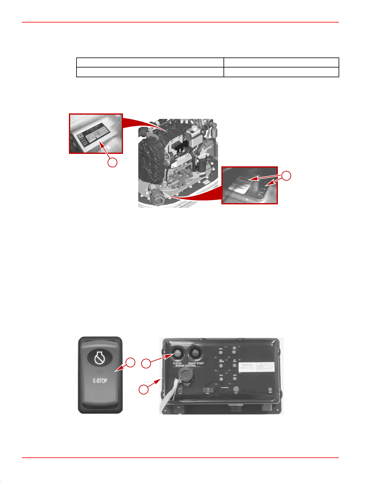
Drive serial number locations
a - Transmission serial number plate
b - Drive serial number decal and stamping
Refer to the engine owners manual supplied with the engine for the location of the engine
data tag that contains the engine serial number and model number.
Features and Controls
E‑Stop (Emergency Stop) Switch, If Equipped
An E‑stop (emergency stop) switch turns off the engines in an emergency situation, such
as a person overboard or a tangled propeller. When activated, an E‑stop switch interrupts
the power supply to the engine and transmission. If the boat is equipped with an E‑stop
switch at the helm, the E‑stop switch turns off all of the engines. The E‑stop switch on a
Vessel Interface Panel (VIP) turns off only the engine connected to VIP.
Typical E‑stop switch at the helm
a - E‑stop switch b - VIP
E-stop switch on a typical VIP
Page 14 90-866938081 MAY 2009
Page 23
Section 2 - Getting to Know Your Power Package
27198
Activation of an E‑stop switch stops the engine, or engines, immediately, but the boat can
continue to coast for some distance depending upon the velocity and degree of any turn
at shutdown. While the boat is coasting, it can cause injury to anyone in the boat's path as
seriously as the boat would when under power.
We recommend instructing other occupants on proper starting and operating procedures
should they need to operate the engine in an emergency.
Accidental or unintended activation of the switch during normal operation is also
possible, which can cause any or all of the following potentially hazardous situations:
• Occupants can be thrown forward due to unexpected loss of forward motion, and
passengers in the front of the boat could be ejected over the bow and possibly struck
by the propulsion or steering components.
• The operator can lose power and directional control in heavy seas, strong current, or
high winds.
• The operator can lose control when docking.
Restarting an engine using the key switch or start button after an E‑stop shutdown without
first turning the key switch to the off position for at least 30 seconds will restart the engine
but cause fault codes to be set. Unless you are in a potentially hazardous situation, turn
the key switch off and wait at least 30 seconds before restarting the engine or engines. If
after restarting some fault codes are still being displayed, contact your Authorized
Cummins MerCruiser Diesel Repair Facility.
Instrumentation
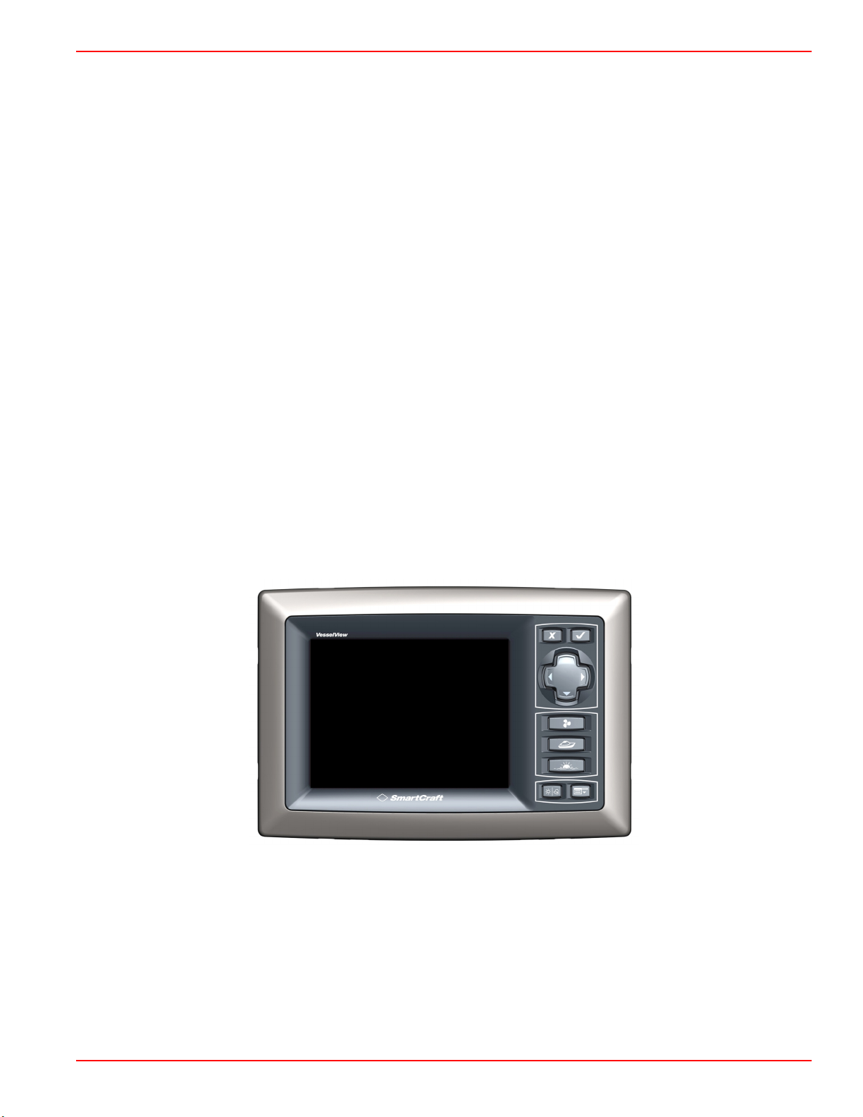
VESSELVIEW
VesselView is the primary information source for the Zeus drive, all engine information,
fault codes, tank levels, boat direction, and calibrations. For more information, refer to the
VesselView Operators Manual.
VesselView
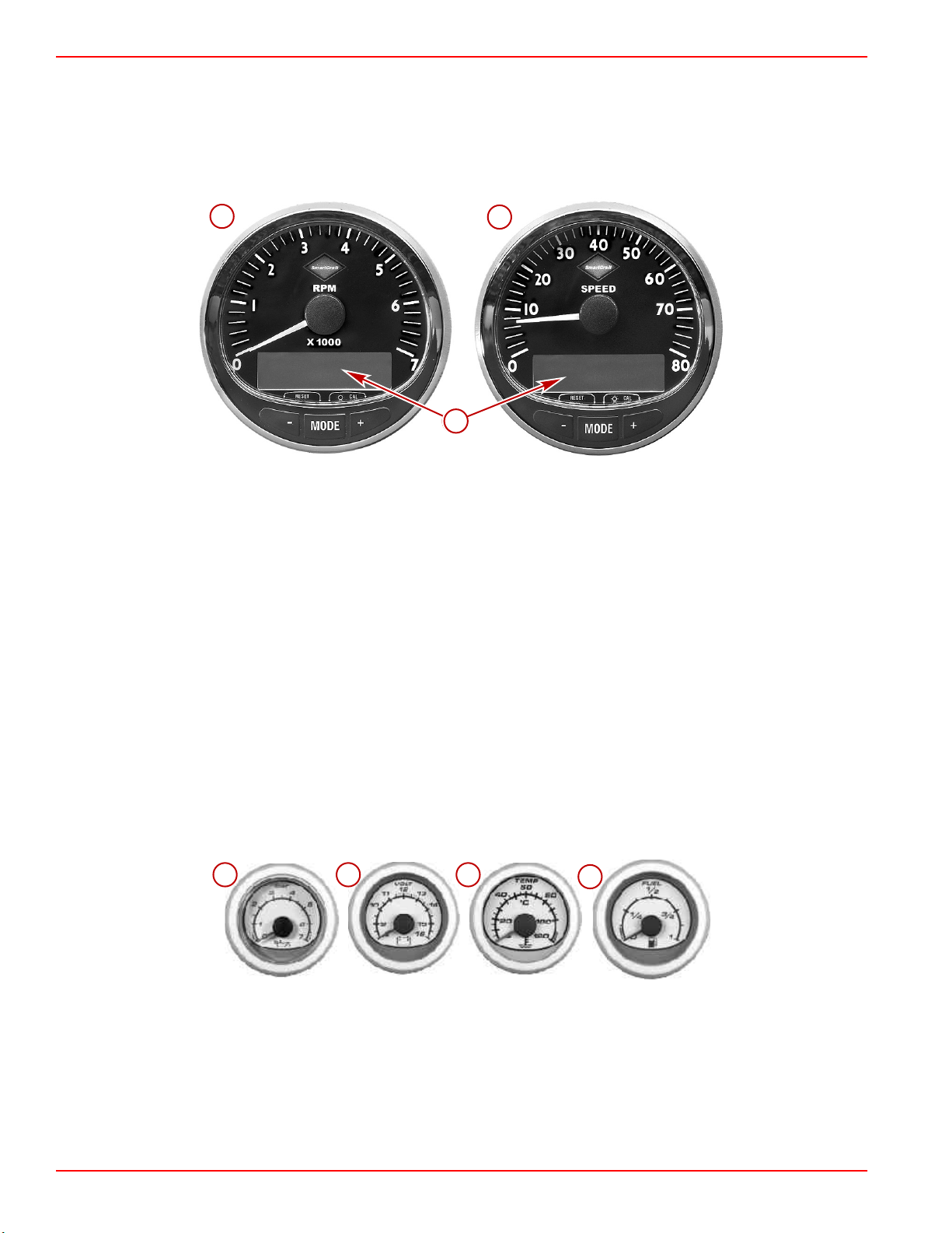
SMARTCRAFT SPEEDOMETER AND TACHOMETER DIGITAL GAUGES (IF EQUIPPED)
The Cummins MerCruiser Diesel SmartCraft instrument package augments the
information provided by VesselView. The instrument package may display:
• Engine RPM
• Boat speed
• Coolant temperature
• Oil pressure
90-866938081 MAY 2009 Page 15
Page 24
Section 2 - Getting to Know Your Power Package
24575
a
b
c
c
abc
d
37925
• Battery voltage
• Fuel consumption
• Engine operating hours
• And more
Typical SmartCraft tachometer and speedometer
a - Tachometer
b - Speedometer
c - LCD System View display
The SmartCraft instrument package also aids in identifying the fault codes associated with
the engine audio warning system. The SmartCraft instrument package displays critical
engine alarm data and other potential problems on its LCD display.
For basic operation information on the SmartCraft Instrument package and for details on
the warning functions monitored by the system, refer to the manual provided with your
gauge package.
SYSTEM LINK DIGITAL GAUGES (IF EQUIPPED)
Some instrumentation packages include gauges that augment the information provided by
VesselView and the SmartCraft Tachometer and Speedometer. The owner and operator
should be familiar with all the instruments and their functions on the boat. Because of the
large variety of instrumentation and manufacturers, have your boat dealer explain the
gauges and normal readings that appear on your boat.
The following types of digital gauges may be included with your power package.
Typical System Link digital gauges
Page 16 90-866938081 MAY 2009
Page 25
Section 2 - Getting to Know Your Power Package
a
b
c
d
Item Gauge Indicates
a Oil pressure gauge Engine oil pressure
b Voltmeter Battery voltage
c Water temperature gauge Engine operating temperature
d Fuel gauge Quantity of fuel in tank
Electronic Helm Steering
The Electronic Helm Steering is a true drive‑by‑wire system that controls the steering
through electronic signals. The feel of the steering is created by computer‑designated
resistance.
We recommend that you drive carefully until you have a chance to explore the Zeus
system's handling characteristics in an open area without obstructions or other boat
traffic, and you are familiar with the boat's responses. The first few maneuvers at speed
can be more abrupt than expected.
Dual‑Handle Electronic Remote Control (ERC)—Features and Operation
OPERATION
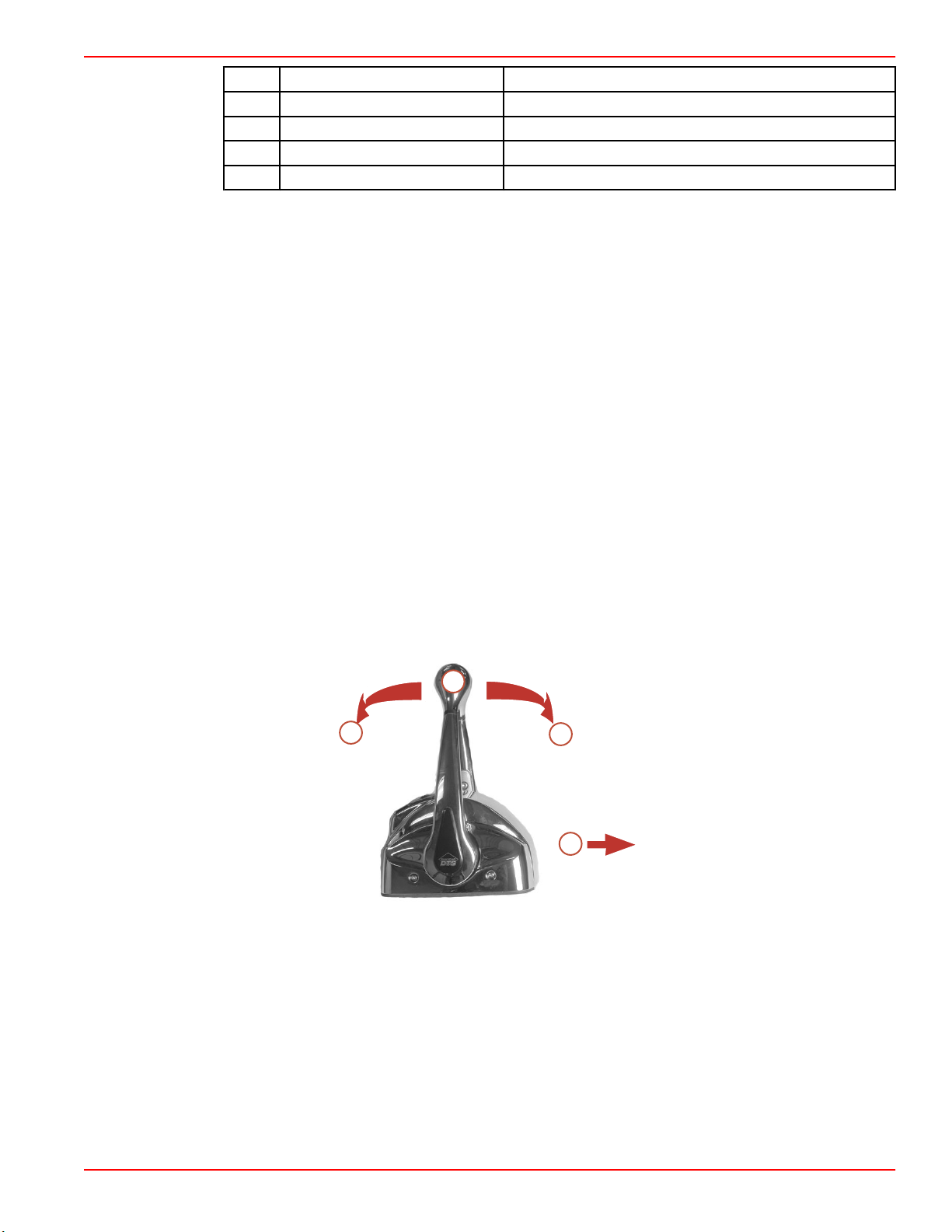
The electronic remote control (ERC) handle controls the operation of shift and throttle. Push
the control handle forward from neutral to the first detent for forward gear. Continue pushing
the handle forward to increase speed. Pull the control handle from the forward position to
the neutral position to decrease speed and eventually stop. Pull the control handle back
from neutral to the first detent for reverse gear. Continue pulling the handle back to increase
speed in reverse.
NOTE: In certain modes, gear position is determined by the position of the shift valves on
the transmission, not the position of the ERC levers. When using the joystick or while in
Skyhook, the computer moves the transmission in and out of gear even though the handles
are in neutral.
28086
a - Neutral
b - Forward
c - Reverse
d - Bow of boat
The amount of force needed to move the ERC handles and to move the ERC handles
through the detents is adjustable to help prevent unwanted motion of the handle in rough
water.
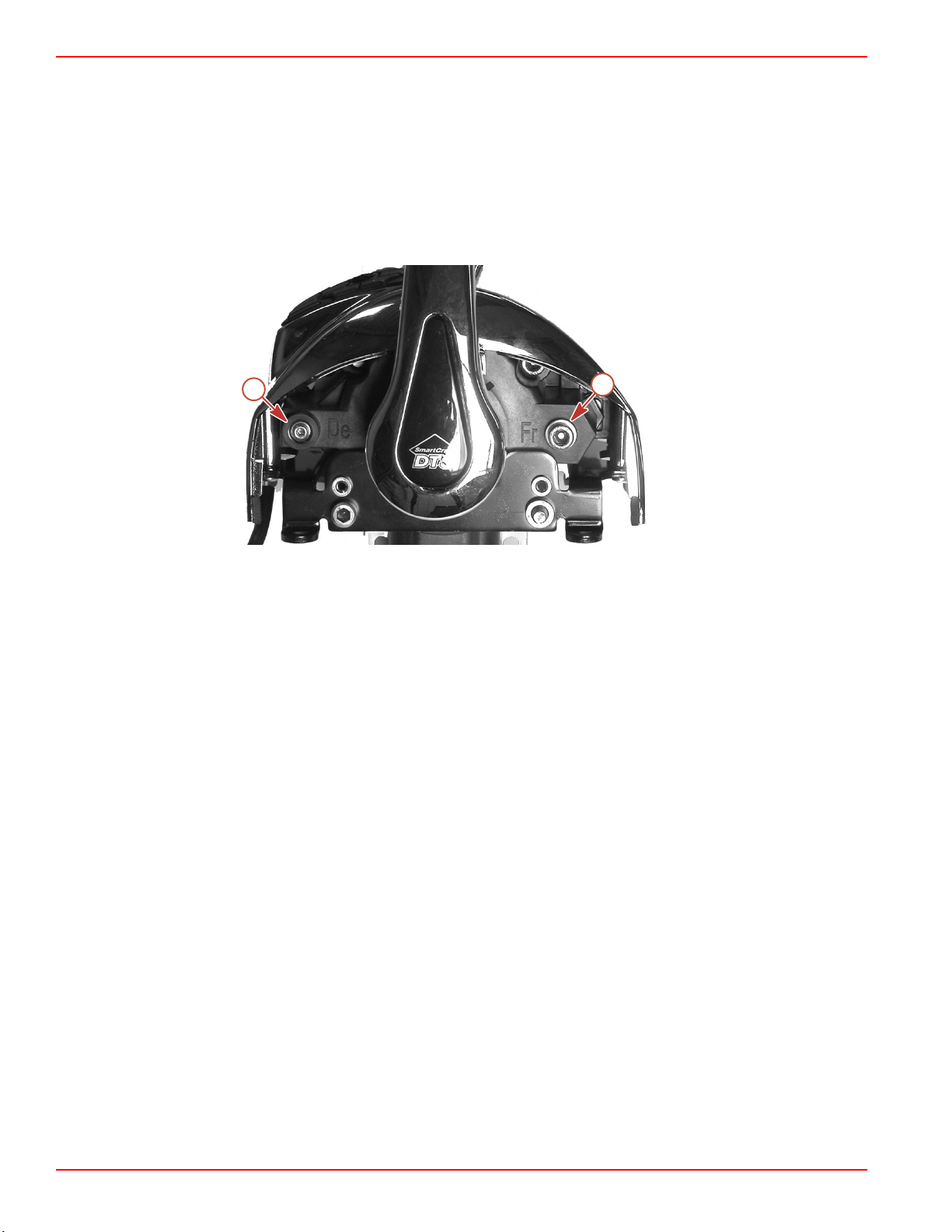
To adjust the ERC handle detent tension:
1. Remove the side cover of the handle needing adjustment.
90-866938081 MAY 2009 Page 17
Page 26
Section 2 - Getting to Know Your Power Package
a
b
2. Turn the adjustment screw clockwise to increase tension on the control handle and
counter‑clockwise to decrease tension.
3. Adjust to tension desired.
To adjust ERC handle tension:
1. Remove the side cover of the handle needing adjustment.
2. Turn the adjustment screw clockwise to increase tension on the control handle and
counter‑clockwise to decrease tension.
3. Adjust to tension desired.
Starboard side cover removed, port similar
a - Detent tension adjustment screw, labeled "De"
b - Handle tension adjustment screw, labeled "Fr"
Basic Joystick Operation
The joystick offers precise, intuitive control of your boat during low speed and docking
maneuvers. The joystick translates the movement of the joystick into similar movement in
the boat. Engine speed is limited in this mode to prevent unacceptable boat dynamics
during maneuvers.
While operation with the joystick is easy to learn, we recommend that you drive the boat
in the traditional way until you can spend time in an open area free of obstructions and
traffic to learn how your boat responds to inputs. Further, we recommend that you
occasionally practice maneuvering in the traditional way to maintain your traditional drive
docking skills in case joystick control is temporarily not available.
Refer to Section 2—Maneuvering with the Joystick, for complete information concerning
joystick operation.
Electrical System Overload Protection
If an electrical overload occurs, a fuse or a circuit breaker opens. Find and correct the cause
for the electrical overload before replacing the fuse or resetting the circuit breaker.
NOTE: In an emergency, when you must operate the engine and cannot locate or correct
the cause for the electrical overload (high current draw), turn off or disconnect all the
accessories connected to the engine and instrumentation wiring. Reset the circuit breaker
or replace the fuse. If the circuit remains open, the electrical overload has not been
eliminated. Contact your Cummins MerCruiser Diesel Authorized Repair Facility to check
the electrical system.
28087
Page 18 90-866938081 MAY 2009
Page 27
Section 2 - Getting to Know Your Power Package
33923
a
b
c
d
e
f
Circuit breakers and fuses provide protection for the electrical system as indicated. The
circuit breakers and fuses are located in various locations throughout the boat. Have your
dealer show you the location and identify the circuit that they protect.
After finding and correcting the cause of the overload, reset the circuit breaker by pressing
the reset button.
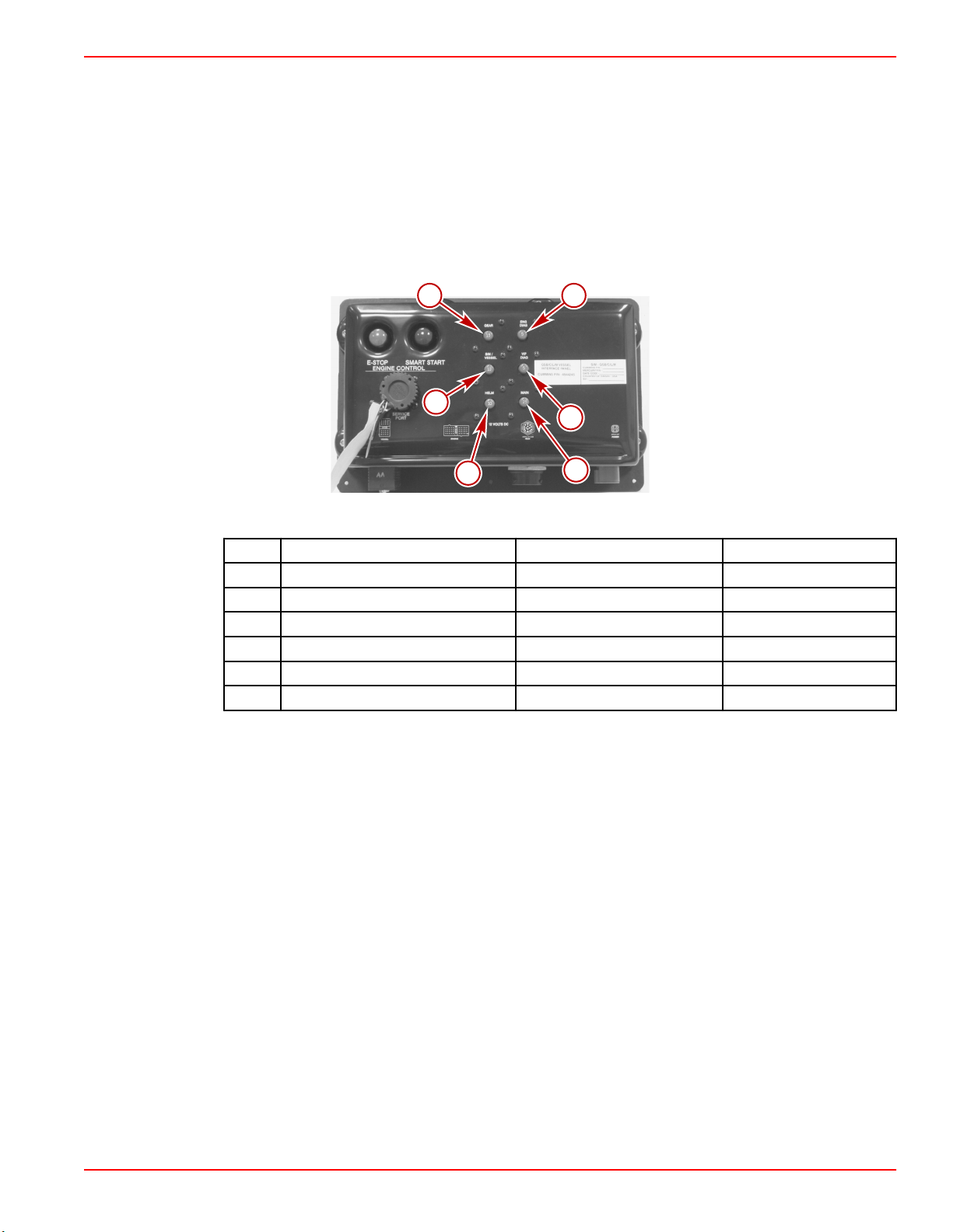
VESSEL INTERFACE PANEL (VIP) OVERLOAD PROTECTION
The Vessel Interface Panel (VIP) contains six circuit breakers that help protect the
transmission harness, engine harness, vessel sensor harness, and helm harness.
NOTE: A VIP for each engine is located in the engine room.
All similar
Item Circuit Breaker Rating Protection Location on VIP
a 15 A Gear Upper left
b 10 A SIM/Vessel Middle left
c 10 A Helm Lower left
d 5 A Engine Diagnostics Upper right
e 5 A VIP Diagnostics Middle right
f 25 A Main Lower right
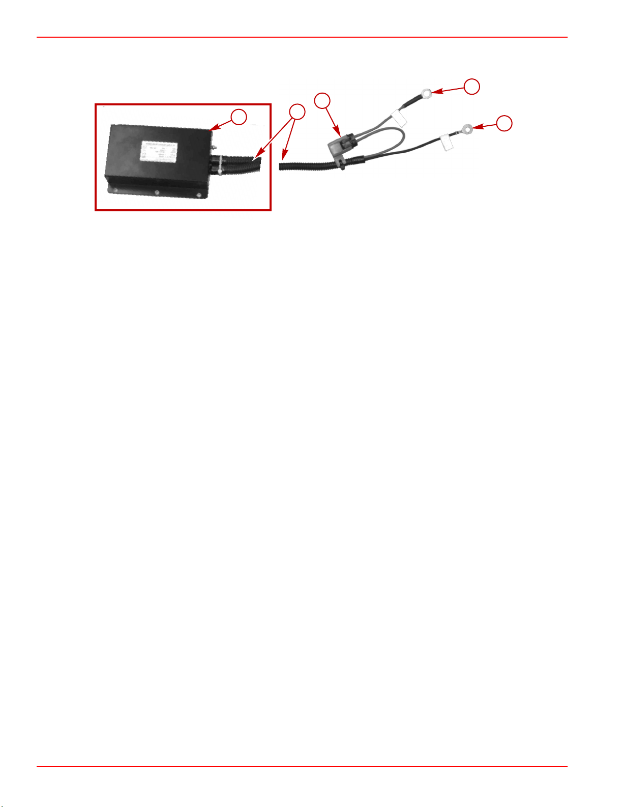
OVERLOAD PROTECTION FOR THE DC VOLTAGE REGULATOR SYSTEM, IF EQUIPPED
If the vessel is equipped with a 24‑volt system, a DC voltage regulator is required to supply
12‑volt power to the VIP and the other 12‑volt circuits. The power package manufacturer
provides a protective fuse for the 24‑volt DC to 12‑volt DC voltage regulator system, if
equipped. The spade‑style, in‑line fuse is located in the harness between the voltage
regulator and the 24‑volt battery system. The fuse protects the wiring and the regulator
against overloads.
90-866938081 MAY 2009 Page 19
Page 28
Section 2 - Getting to Know Your Power Package
BATTERY +
BATTERY -
a
b
c
d
e
37994
NOTE: For additional information on the on‑off switch for the DC voltage regulator, refer
to
Section 3—Getting Started
.
a - DC voltage regulator
b - Wiring to DC voltage regulator
c - 30 ampere fuse and holder
The boat manufacturer may replace the fuse and holder with a circuit breaker. Have your
boat manufacturer or dealer show you the location and identify the fuse or circuit breaker
for your reference.
OVERLOAD PROTECTION FOR OTHER CIRCUITS
Other circuits may be protected by circuit breakers or fuses installed by the boat
manufacturer and can vary in appearance and location.
For example, the MerCathode system has a 20‑amp in‑line fuse in the wire that connects
from the positive (+) battery terminal to the positive (+) terminal on the controller. If the fuse
is defective (open), the system will not operate, resulting in a loss of corrosion
protection. Have your dealer show you the location of and service procedures for the
fuse.
Ask your dealer for the location and operation instructions of all overload protection
devices.
Galvanic Isolator and Monitor
These power packages feature anodes as standard equipment to help protect them from
galvanic corrosion under moderate conditions. The MerCathode System and sacrificial
anodes provide corrosion protection under normal usage.
Boats connected to AC shore power require additional protection to prevent destructive
low‑voltage galvanic currents from passing through the shore‑power ground wire. A
Quicksilver Galvanic Isolator or equivalent isolation device is recommended to block the
passage of these currents while providing a path to ground for dangerous fault (shock)
currents.
IMPORTANT: If AC shore power is not isolated from boat ground, the MerCathode System
and anodes may be unable to handle the increased galvanic corrosion potential.
d - To 24‑volt battery system positive
( +)
e - To 24‑battery system negative (–)
Page 20 90-866938081 MAY 2009
Page 29

Section 2 - Getting to Know Your Power Package
41272
A Quicksilver Galvanic Isolator kit includes an audio and visual monitor to alert you to faults
that occur. The monitor is a microprocessor controlled, solid state device that will test the
integrity of the Quicksilver Galvanic Isolator and the safety grounding lead. This device will
also supply impressed current to the drive to aid in corrosion protection.
WARNING
!
Improperly conducted AC shore power is an electric shock hazard that can result in
damage and injury. The AC grounding conductor green wire must be connected between
the boats electrical system and the shore power connection in order to provide a path for
fault current and to assist the MerCathode in preventing galvanic corrosion on drive
components. Install a galvanic isolator or similar isolation device in the AC shore power
system in the vessel. Consult a qualified marine electrician for more information.
IMPORTANT: If the Galvanic Isolator alarm sounds and the monitor will not respond to the
reset button, AC fault current may be present and the shore power safety grounding
conductor circuit to shore may be an open circuit. Disconnect shore power immediately.
Refer to Troubleshooting—Galvanic Isolator for an explanation of the conditions or
faults that may be displayed by the monitor.
Galvanic Isolator Monitor and conditions
NOTE: If your vessel is equipped with a galvanic isolator from a manufacturer other than
Quicksilver, refer to the instructions provided by the manufacturers.
90-866938081 MAY 2009 Page 21
Page 30

Section 2 - Getting to Know Your Power Package
Notes:
Page 22 90-866938081 MAY 2009
Page 31

Table of Contents
Section 3 - On the Water
Section 3 - On the Water
Safe Boating Suggestions.................................. 25
Be Alert to Carbon Monoxide Poisoning.......26
Good Ventilation ..................................... 26
Poor Ventilation ..................................... 27
Basic Boat Operation.......................................... 27
Freezing Temperature and Cold Weather
Operation......................................................27
Drain Plug and Bilge Pump...........................28
Protecting People in the Water.....................28
While the Boat is Moving ........................ 28
While the Boat is Stationary ................... 29
Wave and Wake Jumping.............................29
Impact with Underwater Hazards..................29
Zeus Drive Impact Protection........................30
Zeus Drive Alignment....................................31
Conditions Affecting Boat Operation.................. 31
Weight Distribution (Passengers and Gear)
Inside the Boat..............................................31
Bottom Of Boat..............................................31
Cavitation......................................................31
Ventilation.....................................................31
Propeller Selection........................................31
Getting Started.................................................... 32
Break‑In Period (New or With Replacement
Gears)...........................................................32
DC Voltage Regulator Switch, If Equipped
......................................................................32
Starting and Stopping the Engines................33
Normal Starting ...................................... 33
Normal Stopping .................................... 35
Starting an Engine Using the VIP SmartStart
Switch ..................................................... 35
Stopping the Engine Using the VIP
SmartStart Switch .................................. 37
Traditional Maneuvering with Steering and
Thrust............................................................38
To Maneuver the Boat in Forward .......... 38
To Steer the Boat in Tight Turns at Low
Speeds ................................................... 38
To Spin the Boat on its Axis at Low Speeds
............................................................... 39
Maneuvering with the Joystick......................39
Trim Tabs......................................................43
Automatic Control ................................... 43
Manual Control ....................................... 44
Using Trim Tab Offset ............................ 44
Special Digital Throttle and Shift
......................................................................45
Troll and Throttle Response ................... 46
Dock ....................................................... 47
Throttle Only ........................................... 47
Single Lever (1 Lever) Operation ........... 48
Synchronizing the Engines ..................... 49
Cruise Control...............................................49
Helm Transfer..................................................... 50
Requesting Helm Transfer............................50
Helm Transfer and Precision Pilot.................51
Precision Pilot..................................................... 51
Precision Pilot Trackpad Features................51
General Information ............................... 51
Standby .................................................. 51
Standby and Active Lights ...................... 52
Power Icon ............................................. 53
Skyhook (If Equipped)...................................53
Engaging (Activating) Skyhook .............. 55
The Skyhook Screen in VesselView ......57
Disengaging (Deactivating) Skyhook .....57
Auto Heading................................................58
Engaging Auto Heading ......................... 58
Course Adjustment Using the Turn Buttons
or Joystick .............................................. 59
To Resume a Heading .......................... 60
Disengaging Auto Heading .................... 60
Response Button...........................................62
Track Waypoint.............................................62
Engaging Track Waypoint Mode ............ 63
Disengaging Track Waypoint Mode ....... 64
Turn Buttons or Joystick in Track Waypoint
Mode ...................................................... 64
Auto Heading Button in Track Waypoint
Mode ..................................................... 64
Acknowledging a Turn During a Waypoint
Arrival ..................................................... 64
Waypoint Sequence ............................... 66
Contingent Operations........................................ 68
Steering—Emergency Alternative Method....68
Port Engine Only Operation..........................69
Gear Engagement—Emergency Procedure
......................................................................69
Steering and Trim—Manual Override...........70
Procedure for a Stuck Steering Control
Valve ...................................................... 72
(DTS) Features
3
90-866938081 MAY 2009 Page 23
Page 32

Section 3 - On the Water
Procedure for a Stuck Trim Tab Control
Valve ...................................................... 73
End of First Season Checkup............................. 73
Page 24 90-866938081 MAY 2009
Page 33

Safe Boating Suggestions
In order to safely enjoy the waterways, familiarize yourself with local and all other
governmental boating regulations and restrictions, and also consider the following
suggestions.
• Know and obey all nautical rules and laws of the waterways.
Cummins MerCruiser Diesel strongly recommends that all powerboat operators complete
a boating safety course. Courses are offered in the U.S.A. by the U.S. Coast Guard
Auxiliary, the Power Squadron, the Red Cross, and your state or provincial boating law
enforcement agency. Inquiries may be made to the Boating Hotline at 1‑800‑368‑5647 or
the Boat U.S. Foundation at 1‑800‑336‑BOAT.
• Perform safety checks and required maintenance. Follow a regular schedule and
ensure that all repairs are properly made.
• Check safety equipment on board. Here are some suggestions of the types of safety
equipment to carry when boating:
Approved fire extinguishers
Paddle or oar
Signal devices: flashlight, rockets or flares, flag, and whistle or horn
Section 3 - On the Water
Transistor radio
Tools necessary for minor repairs
First aid kit and instructions
Anchor and extra anchor line
Waterproof storage containers
Manual bilge pump and extra drain plugs
Spare operating equipment, batteries, bulbs, and fuses
Drinking water
Compass and map or chart of the area
Watch for signs of weather change and avoid foul weather and rough-sea
•
boating.
Tell someone where you are going and when you expect to return.
•
• Passenger boarding. Stop the engine whenever passengers are boarding,
unloading, or are near the back (stern) of the boat. Shifting the drive unit into neutral is
not sufficient.
• Use personal flotation devices. Federal law requires that there be a U. S. Coast
Guard–approved, wearable‑type life jacket (personal flotation device), correctly sized
and readily accessible for every person aboard, plus a throwable cushion or ring. We
strongly advise that everyone wear a life jacket at all times while in the boat.
• Prepare other boat operators. Instruct at least one person aboard in the basics of
starting and operating the engine and handling the boat in case the driver becomes
disabled or falls overboard.
• Do not overload your boat. Most boats are rated and certified for maximum load
(weight) capacities (refer to your boat capacity plate). Know your boat’s operating and
loading limitations. Know if your boat will float if full of water. When in doubt, contact
your authorized Cummins MerCruiser Diesel dealer/distributor or the boat
manufacturer.
90-866938081 MAY 2009 Page 25
Page 34

Section 3 - On the Water
• Ensure that everyone in the boat is properly seated. Do not allow anyone to sit or
•
•
• Be alert. The operator of the boat is responsible by law to maintain a proper lookout
• Never drive your boat directly behind a water skier in case the skier falls. As an
• Watch fallen skiers. When using your boat for water skiing or similar activities, always
• Report accidents. Boat operators are required by law to file a Boating Accident Report
ride on any part of the boat that was not intended for such use. This includes the backs
of seats, gunwales, transom, bow, decks, raised fishing seats, and any rotating fishing
seat; anywhere that sudden unexpected acceleration, sudden stopping, unexpected
loss of boat control or sudden boat movement could cause a person to be thrown
overboard or into the boat. Ensure that all passengers have a proper seat and are in it
before any boat movement.
Never be under the influence of alcohol or drugs while boating (it is the law).
Alcohol or drugs impairs your judgment and greatly reduce your ability to react
quickly.
Know your boating area and avoid hazardous locations.
by sight and hearing. The operator must have an unobstructed view particularly to the
front. No passengers, load, or fishing seats should block the operator's view when
operating the boat above idle or planing transition speed. Watch out for others, keep
your eyes on the the water, and be aware of your wake.
example, your boat traveling at 40 km/h (25 MPH) will overtake a fallen skier who was
61 m (200 ft.) in front of you in five seconds.
keep a fallen or down skier on the operator’s side of the boat while returning to attend
to the skier. The operator should always have the down skier in sight and never back
up to the skier or anyone in the water.
with their state boating law enforcement agency when their boat is involved in certain
boating accidents. A boating accident must be reported if 1) there is loss of life or
probable loss of life, 2) there is personal injury requiring medical treatment beyond first
aid, 3) there is damage to boats or other property where the damage value exceeds
US $500.00 or 4) there is complete loss of the boat. Seek further assistance from local
law enforcement.
Be Alert to Carbon Monoxide Poisoning
Carbon monoxide is present in the exhaust fumes of all internal combustion engines
including the outboards, sterndrives and inboard engines that propel boats, as well as the
generators that power various boat accessories. Carbon monoxide is a deadly gas that is
odorless, colorless and tasteless.
Early symptoms of carbon monoxide poisoning, which should not be confused with
seasickness or intoxication, include headache, dizziness, drowsiness and nausea.
WARNING
!
Carbon monoxide poisoning can lead to unconsciousness, brain damage, or death. Keep
the boat well ventilated while at rest or underway and avoid prolonged exposure to carbon
monoxide.
GOOD VENTILATION
Ventilate the passenger area, open the side curtains or forward hatches to remove
fumes.
Page 26 90-866938081 MAY 2009
Page 35

1. Example of desired air flow through the boat.
POOR VENTILATION
Under certain conditions, permanently enclosed or canvas enclosed cabins or cockpits with
insufficient ventilation may draw in carbon monoxide. Install one or more carbon monoxide
detectors in your boat.
Although the occurrence is rare, on a very calm day, swimmers and passengers in an open
area of a stationary boat that contains or is near an operating engine may be exposed to
a hazardous level of carbon monoxide.
1. Examples of poor ventilation while a boat is stationary:
Section 3 - On the Water
mc79553-1
a
a - Operating the engine when the boat
is moored in a confined space
2. Examples of poor ventilation while a boat is moving:
a
a - Operating the boat with the trim angle
of the bow too high
Basic Boat Operation
Freezing Temperature and Cold Weather Operation
IMPORTANT: If the boat is operated during periods of freezing temperature, take
precautions to prevent freezing damage to the power package. Damage caused by freezing
is not covered by Cummins MerCruiser Diesel Limited Warranty.
NOTICE
Water trapped in the seawater section of the cooling system can cause corrosion or
freeze damage. Drain the seawater section of the cooling system immediately after
operation or before any length of storage in freezing temperatures. If the boat is in the
water, keep the seacock closed until restarting the engine to prevent water from flowing
back into the cooling system. If the boat is not fitted with a seacock, leave the water inlet
hose disconnected and plugged.
b
b - Mooring close to another boat with its
engine operating
b
b - Operating the boat with no forward
hatches open (station wagon effect)
mc79554-1
mc79556-1
NOTE: As a precautionary measure, attach a tag to the key switch or steering wheel of the
boat reminding the operator to open the seacock or unplug and reconnect the water inlet
hose before starting the engine.
In order to operate the engine in temperatures of 0° C (32° F) or lower, observe the following
instructions:
90-866938081 MAY 2009 Page 27
Page 36

Section 3 - On the Water
21604
• At the end of each daily operation, completely drain the seawater section of the cooling
system to protect against damage by freezing.
• At the end of each daily operation, drain the water from the water separator, if
equipped. Fill the fuel tank at end of daily operation to prevent condensation.
• Use the required permanent‑type antifreeze solution to protect components against
damage by freezing.
• Use proper cold weather lubrication oil; ensure that the crankcase contains a sufficient
amount.
• Make certain that the battery is of sufficient size and is fully charged. Check that all
other electrical equipment is in optimum condition.
• At temperatures of –20° C (–4° F) and below, use a coolant heater to improve cold
starting.
• If operating in arctic temperatures of –29° C (–20° F) or lower, consult your Cummins
MerCruiser Diesel Authorized Repair Facility for information about special cold weather
equipment and precautions.
See Section 6 for cold weather or extended storage related information.
Drain Plug and Bilge Pump
The engine compartment in your boat is a natural place for water to collect. For this
reason, boats are normally equipped with a drain plug, a bilge pump, or both a drain plug
and a bilge pump. Install the drain plug and check the operation of the bilge pump, if
equipped, before putting the boat in the water.
Check these items on a regular basis to ensure that the level of water does not come into
contact with your power package. Components on your engine will be damaged if
submerged.
Damage caused by submersion is not covered by the Cummins MerCruiser Diesel Limited
Warranty.
Protecting People in the Water
WHILE THE BOAT IS MOVING
A person in the water may find it very difficult to take quick action to avoid a boat heading
in their direction, even at slow speeds.
Always slow down and exercise extreme caution any time you are boating in an area where
there might be people in the water.
Whenever a boat is moving (even coasting) and the gear shift is in neutral, there is sufficient
force by the water on the propeller to cause the propeller to rotate. This neutral propeller
rotation can cause serious injury.
Page 28 90-866938081 MAY 2009
Page 37

WHILE THE BOAT IS STATIONARY
27301
A spinning propeller, a moving boat, or any solid device attached to the boat can cause
serious injury or death to swimmers. Stop the engine immediately whenever anyone in
the water is near your boat.
Shift into neutral and shut off the engines before allowing people to swim or be in the water
near your boat.
Do not allow people to swim around the boat with the Skyhook Electronic Anchor
engaged. The Skyhook Electronic Anchor causes the drives to move and the propellers to
turn without notice. Having the engines in neutral does not protect the swimmers.
Swimmers in the area of the propellers are at risk of getting injured.
Wave and Wake Jumping
Wave or wake jumping can cause serious injury or death from occupants being thrown
within or out of the boat. Avoid wave or wake jumping whenever possible.
WARNING
!
WARNING
!
Section 3 - On the Water
Operating recreational boats over waves and wakes is a natural part of boating.
However, when this activity is done with enough speed to force the boat hull partially or
completely out of the water, certain hazards arise, particularly when the boat re‑enters the
water.
The primary concern is the boat changing direction while in the midst of the jump. In such
cases the landing may cause the boat to violently veer in a new direction. Such a sharp
change in direction or turn can cause occupants to be thrown out of their seats or out of
the boat.
Impact with Underwater Hazards
Reduce speed and proceed with caution whenever you are driving a boat in shallow water
or in areas where the waters are suspected of having floating or underwater obstacles that
could be struck by the underwater drive components, skegs, or the boat bottom.
mc79680-1
90-866938081 MAY 2009 Page 29
Page 38

Section 3 - On the Water
IMPORTANT: The most important thing you can do to help reduce injury or impact damage
from striking a floating or underwater object is control the boat speed. Under these
conditions, reduce boat speed to a minimum.
The following demonstrate some, but not all, examples of what can happen if the boat
strikes a floating or underwater object:
• The boat could move in a new direction. Such an unexpected change in direction or
• A rapid reduction in speed. This can cause occupants to be thrown forward, even out
• Impact damage to the underwater drive components, skeg, or boat.
Keep in mind that one of the most important things you can do to help reduce injury or
impact damage in these situations is control the boat speed when driving in waters known
to have underwater obstacles.
After striking a submerged object, stop the engine as soon as possible and inspect the
drive systems for any broken or loose parts, and the hull for any damage. If damage is
present or suspected, the power package should be taken to an Authorized Cummins
MerCruiser Diesel Repair Facility for a thorough inspection and any necessary repair.
The boat should be checked for hull fractures, transom fractures, and water leaks.
turn can throw occupants out of their seats or out of the boat.
of the boat.
WARNING
!
Operating a boat with impact damage can result in product damage, serious injury, or
death. If the boat experiences an impact, have an Authorized Cummins MerCruiser
Diesel Repair Facility inspect the vessel and power package and perform repairs as
necessary.
Operating with damaged underwater drive components or boat bottom could cause
additional damage to other parts of the power package, or could affect control of the
boat. If continued operation is necessary, do so at greatly reduced speeds.
Zeus Drive Impact Protection
IMPORTANT: Although the design of the Zeus drive provides some impact protection, no
design can ensure total protection from impact damage under all conditions.
The Zeus drive has some impact protection by design, since the drive is mounted in a
tunnel above the bottom of the hull. If the drive strikes a floating or submerged object while
the boat is moving, the skeg is designed to break away, absorbing some of the impact and
possibly reducing damage to the propellers and the exposed lower part of the drive. In
extreme cases, large fixed or floating objects struck by the skeg and the exposed lower
part of the drive may cause the lower part of the drive to shear off. This shearing off of the
lower part of the drive is a design feature to protect the hull and drive system.
NOTE: If the lower part of the drive shears off due to a severe impact, make immediate
note of the GPS location to assist in recovery efforts. If recovery of the damaged parts of
the drive is possible, return the damaged parts to your Authorized Cummins MerCruiser
Diesel Repair Facility for possible repair and reuse.
If an impact occurs and damage is present or suspected, if the boat does not respond as
it should, or if water is present in the gear lube monitor bottle, have your boat inspected at
the nearest Authorized Cummins MerCruiser Diesel Repair Facility.
Operating in reverse gear offers less impact protection. Use extreme caution when
operating in shallow water or where underwater objects are known to be present. Use
extreme care to prevent striking submerged objects while operating in reverse.
Page 30 90-866938081 MAY 2009
Page 39

Zeus Drive Alignment
The Zeus Drives are aligned by the boat manufacturer, and must not be adjusted by anyone
other than your Cummins MerCruiser Diesel Authorized Service and Repair Facility. The
Zeus drives automatically recalibrate to this setting at each startup. The drives do not need
to be re‑aligned under normal use.
Conditions Affecting Boat Operation
Weight Distribution (Passengers and Gear) Inside the Boat
Shifting weight to the rear (stern):
• Causes the bow to bounce in choppy water.
• Increases the danger of a following wave splashing into the boat when coming off
plane.
• Can cause the boat to porpoise at extremes.
Shifting weight to the front (bow):
• Improves ease of planing.
• Improves rough water ride.
• Can cause the boat to veer back and forth (bow steer) at extremes.
Section 3 - On the Water
Bottom Of Boat
Cavitation
Ventilation
To maintain maximum speed, the boat bottom should be:
• Clean and free of barnacles and marine growth.
• Straight and smooth (fore and aft).
Marine vegetation can accumulate when the boat is docked. Remove this growth before
operation; it can clog the water inlets and outlets, causing the engine to overheat.
Cavitation occurs when water flow cannot follow the contour of a fast‑moving underwater
object, such as a gear housing or a propeller. Cavitation increases propeller speed while
reducing boat speed. Cavitation can seriously erode the surface of the gear housing or the
propeller. Common causes of cavitation are:
• Weeds or other debris snagged on the propeller
• Bent propeller blade
• Raised burrs or sharp edges on the propeller
Ventilation is caused by surface air or exhaust gases that are introduced around the
propeller resulting in propeller speed‑up and a reduction in boat speed. Air bubbles strike
the propeller blade and cause erosion of the blade surface. If allowed to continue, eventual
blade failure (breakage) will occur. Excessive ventilation is usually caused by:
• A missing propeller diffuser ring.
• A damaged propeller or gear housing, which allows exhaust gases to escape between
propeller and gear housing.
Propeller Selection
IMPORTANT: The installed propellers must allow the engine to reach engine Rated Speed
(RPM) with the boat fully loaded and with all customer stores on board. With the boat less
than fully loaded the engines should reach engine Rated Speed (RPM) with less than a
100% load. Use the VesselView display to verify engine RPM and percent load.
90-866938081 MAY 2009 Page 31
Page 40

Section 3 - On the Water
It is the responsibility of the boat manufacturer or the selling dealer to equip the power
package with the correct propellers. Refer to the engine Information Data Tag located on
the engine for the specified engine Rated Speed (RPM). Information for the location of the
engine data tag can be found in the engine owners manual.
If full throttle engine RPM is below the engine Rated Speed (RPM), the propellers will have
to be changed to prevent loss of performance and possible engine damage.
After initial propeller selection, certain issues may require a propeller with a lower pitch.
They include:
• Operating with increased load (additional passengers or gear).
• Shifting the center of gravity of the vessel.
• The addition of towers or canvas.
• Fouling of the hull and running gear.
• High ambient temperatures.
• Operating at high elevation.
It is the responsibility of the boat owner to ensure that the correct propellers are installed
at delivery and maintained over the life of the boat. Because of the many variables of boat
design, only testing will determine the best propeller for a particular boat. If the engine is
not able to reach the engine Rated Speed (RPM), contact your boat builder, boat dealer,
or an Authorized Cummins MerCruiser Diesel Repair Facility for assistance in propeller
selection. A list of propellers for the Zeus drive can be located in the Zeus drive parts
manual. Refer to the Zeus drive Mercury Parts Manual—90-879150112.
Getting Started
Break‑In Period (New or With Replacement Gears)
Always perform these procedures on new drive units. This break‑in procedure allows the
proper seating of drive unit gears and related components, which greatly reduces the
likelihood of problems.
• Avoid full throttle starts.
• Do not operate at any one constant speed for extended periods of time.
• Do not exceed 75% of full throttle during the first 5 hours. During the next 5 hours,
operate at intermittent full throttle.
• Shift the drive into forward gear a minimum of 10 times during break‑in, with run‑in time
at moderate RPM after each shift.
• After the first 25 hours and not to exceed 30 hours, change the transmission fluid and
filter including the transmission fluid in the drop box, if equipped.
• After the first 25 hours and not to exceed 30 hours, change the gear lube in the drive
including the gear lube in the gear lube monitor.
DC Voltage Regulator Switch, If Equipped
If the vessel is equipped with a 24‑volt system, a DC voltage regulator is required to supply
12‑volt power to the VIP and the other 12‑volt circuits. To allow the regulator to be turned
on and off a switch is provided by the boat manufacturer. The switch is on a separate
circuit.
Switching the power on provides regulated power to the VIP and other 12‑volt circuits to
allow the vessel to start. Switching the DC voltage regulator off prevents the regulator from
drawing power when the vessel is not operated.
Have your manufacturer or dealer show you the location and identify the DC voltage
regulator switch for reference.
Page 32 90-866938081 MAY 2009
Page 41

1. Turn the switch on before attempting to start the engine.
a
b
41198
2. Leave the switch on when the vessel is operating.
3. Turn the switch off when the vessel is not operating.
Starting and Stopping the Engines
Your Zeus power package is equipped with a SmartStart system, as well as an engine start
and stop system for emergency use , that is remotely mounted on the VIP for each
engine. The VIP is usually located in the engine room.
In normal circumstances, start and stop the engine from the helm using the start/stop button
of the SmartStart system.
Refer to Section 2—Getting to Know Your Power Package for additional information on
the E‑stop switch used for emergency stopping of the engines.
NORMAL STARTING
1. Perform the drive checks listed in Section 5—Routine Maintenance, Each Day Start
and When Refueling.
2. Perform the checks and steps listed in the engine's operation and maintenance manual
available for this package.
3. Open the seacock for the seawater return. Rotate the handle in the direction indicated
by the arrow.
Section 3 - On the Water
Drive cover removed for clarity
a - Handle in open position
b - Seawater return (overboard) seacock
90-866938081 MAY 2009 Page 33
Page 42

Section 3 - On the Water
a
b
c
41197
4. Open the seacock for the seawater inlet. Rotate the handle in the direction indicated
5. Open the seacock (if equipped) for any accessory equipment.
NOTE: When the key switch is turned to the on position the neutral LED lights, on the ERC
trackpad, flash on and off if the ERC handles are not in the neutral position. Before starting
the engines the ERC handles must be in neutral position, as indicated by the neutral
indicator lights on continuously.
6. Move the ERC handles to the neutral position.
NOTE: Ask your dealer for the location of the key switches if the key switches are not
located at the helm.
7. Turn the key switch to the on position for each engine to be started.
8. Verify it is safe to start the engines.
9. Corresponding to the engine you want to start, do one of the following:
by the arrow.
Typical inlet seacock—port orientation
a - Seacock for seawater inlet
b - Handle in open position
c - Former position (closed)
• Press and release the "START/STOP" switch, if equipped with optional SmartStart
switch panel.
• Turn the key switch to the start position.
The control system automatically controls the starter to achieve a successful start.
28082
Typical SmartStart switch
Page 34 90-866938081 MAY 2009
Page 43

NORMAL STOPPING
a
b
41199
a
c
b
41196
1. Move the ERC handles to the neutral position.
2. Corresponding to the engine you want to stop, and depending on your equipment, do
3. After stopping the engines you may close the seacocks. Rotate the handles in the
Section 3 - On the Water
one of the following:
• Press and release the "START/STOP" switch, if equipped with optional SmartStart
switch panel. Then, turn the respective key switch to the off position.
• Turn the respective key switch to the off position for each engine stopped.
direction indicated by the arrows.
Drive cover removed for clarity
a - Seacock for seawater return
b - Handle in closed position
Typical inlet seacock—port orientation
a - Seacock for seawater inlet
b - Former position (open)
c - Handle in closed position
STARTING AN ENGINE USING THE VIP SMARTSTART SWITCH
You may desire to start an engine from the engine room or under certain circumstances
the engine control systems may not be able to automatically start an engine. The engines
can be started using the "SMARTSTART" (stop/start) switch on the VIP for each engine.
1. Perform the drive checks listed in Section 5-Routine Maintenance, Each Day Start
and When Refueling.
2. Perform the checks and steps listed in the engine's operation and maintenance manual
available for this package.
90-866938081 MAY 2009 Page 35
Page 44

Section 3 - On the Water
a
b
41198
a
b
c
41197
3. Open the seacock for the seawater return. Rotate the handle in the direction indicated
4. Open the seacock for the seawater inlet. Rotate the handle in the direction indicated
by the arrow.
Drive cover removed for clarity
a - Handle in open position
b - Seawater return (overboard) seacock
by the arrow.
Typical inlet seacock—port orientation
a - Seacock for seawater inlet
b - Handle in open position
c - Former position (closed)
5. Open the seacock (if equipped) for any accessory equipment.
NOTE: When the key switch is turned to the on position the neutral LED lights, on the ERC
trackpad, flash on and off if the ERC handles are not in the neutral position. Before starting
the engines the ERC handles must be in neutral position, as indicated by the neutral
indicator lights on continuously.
6. Move the ERC handles to the neutral position.
NOTE: Ask your dealer for the location of the key switches if the key switches are not
located at the helm.
7. Turn the key switch to the on position for each engine to be started.
8. Verify it is safe to start the engines.
9. In the engine room, locate the VIP for each engine.
Page 36 90-866938081 MAY 2009
Page 45

10. Press and release the green "SMARTSTART" (start/stop) switch on the VIP
33930
a
b
33930
a
b
corresponding to the engine being started. The control system automatically controls
the starter to achieve a successful start.
Typical VIP
a - Red "E‑STOP" switch—for emergency use only
b - Green "SMARTSTART" (start/stop) switch
STOPPING THE ENGINE USING THE VIP SMARTSTART SWITCH
You may desire to stop an engine from the engine room or under certain circumstances
the engine control system may not be able to automatically stop an engine. The engines
can be stopped using the "SMARTSTART" (stop/start) switch on the VIP for each engine.
1. Move the ERC handles to the neutral position.
2. Locate the VIP for each engine in the engine room.
3. When the engines are running, press and release the green "SMARTSTART" (stop/
start) switch for each engine you want to stop.
Section 3 - On the Water
Typical VIP
a - Red "E‑STOP" switch—for emergency use only
b - Green "SMARTSTART" (start/stop) switch
4. Turn the key switch to the off position for each engine that was stopped.
90-866938081 MAY 2009 Page 37
Page 46

Section 3 - On the Water
a
b
41199
a
c
b
41196
5. After stopping the engines you may close the seacocks. Rotate the handles in the
direction indicated by the arrows.
Drive cover removed for clarity
a - Seacock for seawater return
b - Handle in closed position
Typical inlet seacock—port orientation
a - Seacock for engine seawater inlet
b - Former position (open)
c - Handle in closed position
Traditional Maneuvering with Steering and Thrust
You can maneuver your Zeus‑equipped vessel much like a traditional inboard boat.
However, the Zeus drive system expands the maneuvering capability of your vessel at both
slow and planing speeds. At slow speeds, the drive system is capable of directing the thrust
to produce more responsive turning of the vessel. The Zeus drive system features
counter‑rotating propellers that do not produce any sideways motion when accelerating or
slowing down.
NOTE: During slow‑speed turning with the wheel, the drive on the inside turns as much as
42° to create very tight turns. Different from traditional boats, to tighten the turn, you can
increase power to the inside drive.
TO MANEUVER THE BOAT IN FORWARD
Place one or both engines in forward gear and steer with the steering wheel as you would
any comparable boat.
TO STEER THE BOAT IN TIGHT TURNS AT LOW SPEEDS
1. To turn the boat in tight turns at low speeds, turn the wheel in the direction of the turn.
2. To increase the turn rate of the boat after the wheel is completely turned, you may
increase the power to the inside drive.
Page 38 90-866938081 MAY 2009
Page 47

TO SPIN THE BOAT ON ITS AXIS AT LOW SPEEDS
25911
1. Center the steering wheel.
2. To spin to the right, place the starboard engine in reverse and the port engine in
forward.
3. To spin to the left, place the port engine in reverse and the starboard engine in
forward.
4. To increase the rate of turn, simultaneously adjust each ERC lever for more throttle.
Maneuvering with the Joystick
The joystick provides single lever interface to maneuver the vessel. Operating the vessel
with the joystick is well suited for close quarter operations and when docking. The joystick
causes the control system to independently control each pod angle and thrust to move or
rotate the boat in a desired direction. For example, if you move the joystick sideways, the
control system commands the boat in the sideways direction.
The joystick gives three axis control: fore and aft, port and starboard, and rotational, or any
combination thereof. For example, moving the joystick to port causes the boat to move
sideways to port. Rotating the joystick causes the boat to rotate around its center. You can
move and rotate the joystick at the same time, allowing for very intricate movements for
maneuvering in tight quarters.
The control system automatically attempts to dampen bow and stern swinging (referred to
as yaw) during joystick operation. An on‑board sensor measures the yaw rate of the boat
and actively counteracts the yaw motion of the boat. Factors, such as wind, water
conditions or vessel loading, may act upon the vessel beyond the systems capability to
correct yaw. Manual yaw correction may be required when commanding the boat in the
fore and aft, port and starboard, or diagonal directions. To correct for unintended yaw
during any maneuver just rotate the joystick in the direction the bow is desired to rotate.
The following table gives some limited examples of the basic responses to inputs from the
joystick. The joystick is proportional, which means that the farther from the center the
joystick is moved, the more thrust is applied to the boat in that direction.
To maneuver the boat with the joystick:
1. Move both electronic remote control (ERC) levers to the neutral position.
2. Move the joystick in the direction that you want the boat to move, or twist the joystick
in the direction that you want the boat to rotate. The joystick can be moved and rotated
at the same time.
Joystick Input and Boat Response Table
Section 3 - On the Water
Joystick Input
24704
Boat Response
Boat at rest
(shown from light gray to dark gray)
Movement
90-866938081 MAY 2009 Page 39
Page 48

Section 3 - On the Water
25928
25927
25929
25931
Joystick Input Boat Response
Boat moves forward
24705
Boat moves aft
Movement
(shown from light gray to dark gray)
24706
24707
Boat moves to starboard
without rotating
Boat moves to port
without rotating
24708
Page 40 90-866938081 MAY 2009
Page 49

Section 3 - On the Water
25926
37774
25924
25923
Joystick Input Boat Response
Boat moves diagonally
forward and to the
starboard without rotating
24709
NOTE: In this maneuver
move and twist the
joystick for yaw
correction, if required.
Boat moves diagonally
forward and rotates
starboard for yaw
correction
Movement
(shown from light gray to dark gray)
24715
24710
Boat moves diagonally aft
and to the starboard
without rotating
Boat moves diagonally aft
and to the port without
rotating
24711
90-866938081 MAY 2009 Page 41
Page 50

Section 3 - On the Water
25925
25921
25920
25916
Joystick Input Boat Response
Boat moves diagonally
forward and to the port
without rotating
24712
Boat rotates clockwise
Movement
(shown from light gray to dark gray)
24713
Boat rotates counter
clockwise
24714
Boat moves diagonally
forward and to the
starboard while rotating
clockwise
24715
Page 42 90-866938081 MAY 2009
Page 51

Section 3 - On the Water
25918
25917
25930
Joystick Input Boat Response
Boat moves diagonally
forward and to the
starboard while rotating
counterclockwise
24718
Boat moves diagonally
forward and to the port
while rotating
counterclockwise
Movement
(shown from light gray to dark gray)
Trim Tabs
AUTOMATIC CONTROL
The Zeus drive comes equipped with an automatic trim tab control feature that operates
through the vessel control system to provide basic performance and efficiency
improvements under normal conditions.
The automatic trim tab control feature can be engaged (turned on) or disengaged (turned
off). To engage the feature, press the "AUTO" trim tab button once. The trim tabs will
automatically adjust as the speed of the boat is changed. Pressing it again will disengage
the feature.
With the automatic trim tab control feature engaged the port and starboard trim tab switches
can be used to adjust the tabs (offset) for natural conditions that affect the attitude of the
boat. This setting of the trim tab offset continues until the automatic control feature is
disengaged and engaged again or when the key switch is cycled (turned off and on).
24719
Boat moves to the port
while rotating clockwise
24720
90-866938081 MAY 2009 Page 43
Page 52

Section 3 - On the Water
Manual trim tab control is available to allow trim tab adjustment when not using the
automatic trim tab control feature. See Manual Control.
NOTE: The port or starboard manual trim tab rocker switches allow some control of the
attitude of the vessel. As an example, to achieve a port bow down attitude, you may press
the port bow down rocker switch to deploy the trim tab on the starboard drive and provide
the requested vessel attitude adjustment.
MANUAL CONTROL
To manually control or adjust the offset of the trim tabs for your conditions, use the individual
port or starboard trim tab switches as needed. Manually adjusted trim tabs will stay in the
position set by the operator until the key switch is cycled off and on or the "AUTO" button
is pressed. If the "AUTO" button is pressed, the automatic trim tab control feature is
engaged and the trim tabs move to a position based on boat speed. See Automatic
Control.
NOTE: When controlled manually the trim tabs do not move during acceleration unless
the operator presses the trim tab buttons.
USING TRIM TAB OFFSET
Automatic or manual control of trim tab offset could be beneficial in the following
conditions.
26318
Typical automatic and manual trim tab switches
During initial acceleration the trim tabs are automatically adjusted (automatic
control) or must be manually adjusted (manual control) to bring the boat on plane
faster (bow down), to improve forward visibility, and use less power. As the boat
comes on plane in automatic control, the trim tabs are brought up so the boat does
Getting on Plane
Smoothing the Ride
Correcting a List
not run with the bow too far down. For the best performance as the boat comes
on plane in manual control, the port and starboard trim tabs must be adjusted up
so the boat does not run with the bow too far down. In automatic control, the trim
tabs can be adjusted (offset) with the port and starboard trim tab switches for best
performance when the boat conditions are temporarily outside the normal
operating conditions.
To avoid an uncomfortable, jarring ride in certain sea conditions, adjust the trim
tabs using either automatic control or manual control. As the wave throws the bow
up trim tabs dampen the boat's reaction, leveling and smoothing the ride. In a
following sea, put the trim tabs up. This allows the bow to lift, offsetting the
waves, which lift the stern. In milder water some boats gently porpoise. Lower the
trim tabs, a little at a time, until the lope disappears.
A boat list (leaning to port or starboard) can be caused by unbalanced load or
several sea and weather conditions. Using the port or starboard trim tab
switches, individual trim tab adjustments can be made in automatic control or
manual control to correct a list.
Page 44 90-866938081 MAY 2009
Page 53

In controlled speed zones, many boats start to fall off plane as speed
c
def
g
bah
Low Speed Trim
decreases, thereby reducing visibility. In automatic control or manual control,
lowered trim tabs keep the boat on plane longer at lower speeds while maintaining
a level boat attitude.
Special Digital Throttle and Shift (DTS) Features
The DTS system features several alternate operational modes for the electronic remote
control (ERC) levers. Most of the listed features can be operated simultaneously and can
help you with:
• Warming the engines.
• Trolling the vessel.
• Docking the vessel.
• Synchronizing the engines.
• Dual helm station transfer.
Section 3 - On the Water
28090
ERC with DTS trackpad
Item Control Function
Illuminate when the transmission is in the neutral gear
a "NEUTRAL" lights
b "TROLL"
c "TRANSFER"
d "DOCK"
e "THROTTLE ONLY"
f "1 LEVER"
g "SYNC"
h "+" (increase) and "–" (decrease)
position. The lights flash when the engine is in throttle only
mode.
Troll reduces the propeller speed to lower than that of engine
speed for the first 25% of lever travel.
Allows boat control to be transferred to a different helm. Refer
to Dual Helm Station Transfer.
Reduces the throttle capacity to approximately 50% of normal
throttle.
Allows the boat operator to increase engine RPM for
warm‑up, without shifting the transmission into gear.
Enables the throttle and shift functions of both engines to be
controlled by the starboard lever.
Turns the auto‑synchronization feature off or on. Refer to
Synchronizing Engines.
Increases and decreases idle speed only. The RPM range
varies depending on application and engine model.
NOTE: Not all functions may be active.
90-866938081 MAY 2009 Page 45
Page 54

Section 3 - On the Water
TROLL AND THROTTLE RESPONSE
Troll mode allows the vessel to operate at very low speeds by controlling the
transmission. The transmission is capable of reducing the propeller speed lower than the
engine speed. Lever control is adjusted so that trolling occurs within the first 25% of lever
travel. From 26% to 100% lever travel the engine operates between idle speed and
maximum rated engine speed.
31463
"TROLL" button
To engage Troll mode:
1. Place both ERC levers in neutral.
2. Press the "TROLL" button, located on the DTS trackpad attached to the ERC levers.
3. Place either ERC lever into gear.
4. The "TROLL" button lights when the lever or levers are moved out of neutral.
5. The RPM of the engines do not change for the first 25% of ERC lever travel while the
transmissions allow some slippage at lower speeds. Engine RPM rises through the
remaining 75% of lever travel.
To disengage Troll mode:
1. Bring both ERC levers to neutral.
2. Press the "TROLL" button. The "TROLL" button light turns off.
Page 46 90-866938081 MAY 2009
Page 55

DOCK
THROTTLE ONLY
Section 3 - On the Water
Dock mode reduces the percent of throttle throughout the range by 50%. This allows better
control of engine power in close quarter situations.
31464
"DOCK" button
To engage Dock mode:
1. Place both ERC levers in neutral.
2. Press the "DOCK" button located on the DTS trackpad attached to the ERC levers.
3. The "DOCK" button light turns on.
4. Place either ERC lever into gear.
5. The engines raise the RPM at a proportionally lower RPM for the ERC lever position,
and with half the power that is usually available.
To disengage Dock mode:
NOTE: Dock only disengages with the levers in a detent.
1. Bring both ERC levers to forward, neutral, or reverse detent.
2. Press the "DOCK" button. Dock mode disengages and the "DOCK" button light turns
off.
To engage Throttle Only mode:
1. Place both ERC levers in neutral.
90-866938081 MAY 2009 Page 47
Page 56

Section 3 - On the Water
2. Press the "THROTTLE ONLY" button, located on the DTS trackpad.
"THROTTLE ONLY" button
3. The "THROTTLE ONLY" button light illuminates and the neutral lights blink.
4. Place either ERC lever into gear.
5. The RPM of the engines can be raised, while the transmissions remain in neutral.
To disengage Throttle Only mode:
NOTE: Pressing the "THROTTLE ONLY" button while the ERC levers are in gear, turns
off the button light, but the boat remains in Throttle Only mode until you place the levers in
neutral.
1. Bring both ERC levers to neutral. Throttle Only will not disengage unless the ERC levers
are in neutral.
2. Press the "THROTTLE ONLY" button. The "THROTTLE ONLY" button light turns off.
3. Notice that the neutral lights remain on.
SINGLE LEVER (1 LEVER) OPERATION
The Zeus single lever (1 Lever) feature simplifies engine management during rough sea
conditions by allowing you to grasp a single lever to command both engines
simultaneously.
To engage the single lever (1 Lever) mode:
1. Place both ERC levers in neutral.
2. Press the "1 LEVER" button located on the DTS trackpad attached to the ERC levers.
31465
31466
"1 LEVER" button
Page 48 90-866938081 MAY 2009
Page 57

3. The "1 LEVER" button light turns on.
4. Place the starboard ERC lever into gear.
5. The engine RPM raises and lowers simultaneously while the transmissions remain in
the same gear.
To disengage the single lever (1 Lever) mode:
1. Place both ERC levers in neutral.
2. Press the "1 LEVER" button. The "1 LEVER" button light turns off.
SYNCHRONIZING THE ENGINES
The system features an automatic engine synchronization feature called Sync. Sync
engages automatically at key‑up. The synchronization feature monitors the position of both
ERC levers. If both levers are within 10% of one another, the port engine synchronizes to
the starboard engine's RPM.
VesselView shows an orange icon if the RPM of the engines are not within 10% of each
other, and the icon turns green when they synchronize. The icon turns grey when Sync
mode is off.
To disengage Sync mode:
1. Place the ERC levers in any detent.
2. Press the "SYNC" button.
Section 3 - On the Water
31467
"SYNC" button
To re‑engage Sync mode, press the "SYNC" button.
Cruise Control
The VesselView system features integrated throttle cruise control called Cruise, which
allows the operator to limit the peak RPM of choice below wide open throttle (WOT). Refer
to the owners manual provided with your VesselView for operation instructions.
These additional notes are exclusive to your package:
• You can change or disengage Cruise through the VesselView screen at any time.
• Cruise resets when the key is turned off.
• If the cruise limit is changed while the levers are at WOT, Cruise gradually changes to
the new speed.
• Cruise does not disengage if the ERC levers are at a higher engine speed than the
actual RPM. Bring the levers back to the forward detent, then use VesselView to
disengage Cruise.
• Skyhook does not function if Cruise is engaged.
90-866938081 MAY 2009 Page 49
Page 58

Section 3 - On the Water
SYNC
1 LEVER
NEUTRAL
TROLL
THROTTLE
ONLY
DOCK
TRANSFER
+
-
22593
Helm Transfer
Some boats are designed to allow control of the vessel from more than one location. These
locations are commonly referred to as helms or stations. Helm transfer is a term used to
describe the method of transferring control from one helm (or station) to another helm.
Avoid serious injury or death from loss of boat control. The boat operator should never
leave the active station while engine is in gear. Helm transfer should only be attempted
while both stations are manned. One‑person helm transfer should only be performed
while engine is in neutral.
The helm transfer function allows the boat operator to select which helm is in control of the
vessel. Before a transfer can be initiated the ERC levers at the active helm and at the helm
intended for the transfer must be in the neutral position.
NOTE: If you attempt to transfer helm control when the ERC levers are not in neutral, a
beep will sound and the helm transfer will not succeed until the levers at the helms are
moved to neutral and transfer is requested again.
Some fault codes may appear on VesselView if other control or navigation functions are
attempted after the helm transfer procedure is started. To remove the fault codes it may
be necessary to cycle the key switch off and on, and then restart the helm transfer
procedure. Ensure that other control and navigation inputs are performed after helm
transfer is complete to avoid setting fault codes.
WARNING
!
The ERC levers must be in neutral to perform a helm transfer. While in neutral your vessel
could drift and collide with objects nearby resulting in damage. Keep an adequate look
out while performing the helm transfer.
To avoid damage, use extra care when attempting a helm transfer while the vessel is close
to docks, piers, or other fixed items or when near other vessels.
Requesting Helm Transfer
NOTE: Any movement of the joystick or ERC levers after pressing the "TRANSFER" button
terminates the helm transfer request. A single beep sounds and the transfer button light
turns off signaling the end of the transfer request.
To request the transfer of vessel control from one helm to another:
1. At the helm you are requesting be made active and with the ERC levers in neutral,
press the "TRANSFER" button one time. After the "TRANSFER" button is pressed, the
transfer button light turns on and one beep will sound confirming the impending
transfer.
NOTICE
"TRANSFER" button
Page 50 90-866938081 MAY 2009
Page 59

NOTE: If the ERC levers at the helms are not in neutral, the neutral lights will flash. Move
all the ERC levers to neutral and the neutral light should then be on.
2. With the "TRANSFER" button light and neutral light on, press the "TRANSFER" button
a second time to complete the helm transfer.
3. When the helm transfer is complete, another beep sounds and the transfer button light
turns off.
NOTE: If the helm transfer is not completed in ten seconds the request is automatically
cancelled and a double beep sounds. Control will remain at the existing active helm. Press
the "TRANSFER" button again to restart helm transfer.
4. The helm where the transfer request was initiated is now active and controls the
vessel.
Helm Transfer and Precision Pilot
Transferring control from an active helm to an inactive helm (from one station to another
station) affects the functionality of Precision Pilot modes. Some of the affects are listed.
• Auto Heading mode is disengaged when the ERC levers are moved to neutral for helm
transfer. You must re‑engage Auto Heading at the newly active helm.
• Requesting a helm transfer causes Pilot to go to Standby mode. You will need to input
information at the new helm in control.
• If engaged, Skyhook will disengage when the "TRANSFER" button is pressed the
second time. You must engage Skyhook at the the newly active helm.
• The Resume feature for Auto Heading does not transfer automatically. After engaging
the previous Auto Heading course at the newly active helm, the resume feature works
the same as at any active station.
• In Track Waypoint mode the control of the route and display of route data on your chart
plotter does not automatically transfer to the chart plotter at the requested helm. You
must turn on the chart plotter at the newly active helm, input the waypoint or waypoint
route to be tracked, and re‑engage Track Waypoint.
Section 3 - On the Water
Precision Pilot
Precision Pilot Trackpad Features
GENERAL INFORMATION
Precision Pilot trackpad features includes:
• Precision Pilot (or Pilot) functions are controlled through the Pilot trackpad only.
• Pilot screens are located under the Environment chapter of VesselView.
• The "TURN" buttons provide a 10° course correction for each press to the port or
starboard.
• The "AUTO HEADING", "TRACK WAYPOINT", and "WAYPOINT SEQUENCE"
buttons engage automatic course and heading modes.
• The steering wheel feels locked into a detent when Auto Heading or Track Waypoint
are engaged. Manually overcoming the detent force of the steering wheel automatically
puts Pilot into Standby mode.
STANDBY
The elements of the Standby screen are:
• In standby mode, the display shows a digital compass value and the angle of the
drives.
• The compass value is the actual current heading from Pilot.
90-866938081 MAY 2009 Page 51
Page 60

Section 3 - On the Water
31408
b
c
a
d
a
b
• On the right side of the screen, an icon labeled "OFF" indicates that Pilot is not
NOTE: Not all of the functions of Precision Pilot work when DTS functions are engaged.
Disengage the DTS functions to use the functions of Precision Pilot.
engaged.
Standby screen on VesselView
a - "OFF" icon
b - Heading
c - Drive angle reference
d - Engine RPM
STANDBY AND ACTIVE LIGHTS
Precision Pilot is disengaged (off) when the "STANDBY" light is illuminated. You must press
the button for Auto Heading, Track Waypoint, or Skyhook to engage a mode.
When the "ACTIVE" light is illuminated one mode of Precision Pilot is engaged (on).
a - "STANDBY" light
b - "ACTIVE" light
27695
Page 52 90-866938081 MAY 2009
Page 61

POWER ICON
a
b
c
Section 3 - On the Water
The power icon located on the buttons for Skyhook, Auto Heading, and Track Waypoint
indicate that the buttons can engage or disengage the Precision Pilot function they
perform.
27696
Buttons with Power icons
a - "SKYHOOK" button
b - "AUTO HEADING" button
c - TRACK WAYPOINT" button
If you press a button that has the power icon when that button light is on, the light turns
off for that button and the "STANDBY" light illuminates.
If you press a button that has the power icon when that button light is off, the light turns
on for that button, a single beep sounds, and the "ACTIVE" light illuminates, unless another
mode is currently active. If another mode is currently active, press the button on the active
mode to disengage it, then press the button for the new mode.
If you press a button with the power icon
for that button, a single beep sounds, and the "ACTIVE" light illuminates.
Skyhook (If Equipped)
Your vessel may be equipped with a station keeping feature called Skyhook. Skyhook
automatically maintains the heading and position of the boat within about 3 meters (10
feet) of a set position. The control system for Skyhook uses GPS and compass heading
information to automatically control shift, throttle and steering to keep the boat in
approximately one position.
The Skyhook feature can hold your boat nearly stationary, for example, while you wait for
a space at the fuel dock, or while waiting for a bridge to open. You can also use Skyhook
to maintain your boat's position when the water is too deep for an anchor.
To unlock and be able to use this feature you will have to contact your Authorized Cummins
MerCruiser Diesel Repair Facility.
when that button light is off, the light turns on
90-866938081 MAY 2009 Page 53
Page 62

Section 3 - On the Water
Skyhook should not be used when the boat is next to a dock, or any other object, including
other anchored boats. Because Skyhook holds the boat in an approximate position, not a
precise one, it can cause your boat to collide with objects close to the boat causing damage
to the boat and the nearby objects. Occasionally the Skyhook system may apply a brief
surge in power while holding a position. This may cause a person standing near the edge
of the boat to lose their balance and fall.
A rotating propeller, a moving boat, or a device attached to a moving boat can cause
serious injury to people in the water. When Skyhook is engaged, the propellers rotate
and the boat moves to maintain the position of the boat. Stop the engines immediately
whenever anyone is in the water near the boat.
To engage Skyhook the drives must be shifted into neutral. However, after engaging
Skyhook the drive response is not the same as with drives normally shifted into neutral.
The propellers will turn when Skyhook is activated, and propeller rotation may not be
obvious. As in all boats when the engines are running, it is important to ensure no one is
in the water near the boat and to make sure passengers are secure. Compliance with this
practice is even more important when Skyhook is engaged.
Before engaging (activating) Skyhook the operator must:
• Inform passengers how Skyhook operates, to stay out of the water and off the swim
• Check to see no one is on the swim platform, or in the water anywhere near the boat.
When Skyhook is engaged the operator must:
• Remain at the helm and maintain a vigilant watch.
• Disengage (deactivate) Skyhook if anyone enters the water or approaches the boat
The capability of Skyhook to maintain the position of the boat in a current is dependent on
the characteristics of the boat. If you notice your boat drifting sideways while Skyhook is
engaged, move the bow or stern more directly into the current to help reduce the effects
of the current.
WARNING
!
platform, and to be alert for any sudden shifts in the boats position.
from the water.
WARNING
!
When the Skyhook is engaged, the boat stays in a preset position; however, Skyhook
can disengage unexpectedly. When Skyhook disengages, the boat does not hold the
preset position and may drift, causing the potential of damage or personal injury. The
helm operator must be able to take control of the boat when using Skyhook.
Skyhook relies on an operational GPS receiver and operational heading sensor.
Occasionally, due to imperfect satellite communications, the GPS signal may be
temporarily unavailable. Skyhook continues to operate through a GPS signal outage for
up to 10 seconds, but automatically disengages if the GPS signal outage persists. If
Skyhook disengages, you are alerted by the sound of a horn and the indicator light on the
Precision Pilot keypad for the "SKYHOOK" button turns off. In such a circumstance, the
boat will drift with the wind or current because the engines continue to run but the drive
units are now in neutral.
Page 54 90-866938081 MAY 2009
Page 63

Skyhook performance is largely dictated by the performance of the onboard Zeus GPS
33798
8M0034159
33824
system. The Zeus GPS system is accurate within 3 meters (10 feet) when receiving a Wide
Area Augmentation System (WAAS) correction. WAAS is a system of satellites and ground
stations that provide GPS signal corrections, allowing for more accurate positioning of your
GPS. When WAAS is not available, the performance of the system maintains the boat
within 20 meters (60 feet) of the desired position.
ENGAGING (ACTIVATING) SKYHOOK
IMPORTANT: Activities in the water near the vessel while Skyhook is engaged may result
in injury. The Captain (or operator) and passengers should read and observe the warning
labels on the boat before Skyhook is engaged.
Section 3 - On the Water
Label adjacent to the Precision Pilot trackpad
Label in the vicinity of the transom boarding area
IMPORTANT: If either of the labels cannot be located or are not legible, they must be
replaced before engaging Skyhook. For replacement labels, contact the manufacturer of
your boat, your Cummins distributor, or an Authorized Cummins MerCruiser Diesel Repair
Facility.
1. Move the ERC levers to neutral and bring the boat to a stop. Skyhook will not engage
until the boat is in neutral and at a speed slow enough for safe engagement.
2. Inform passengers how Skyhook operates, to stay out of the water and off the swim
platform, and to be alert for any sudden shifts in the boats position.
3. Check to see no one is on the swim platform, or in the water anywhere near the boat.
90-866938081 MAY 2009 Page 55
Page 64

Section 3 - On the Water
33920
A rotating propeller, a moving boat, or a device attached to a moving boat can cause
serious injury to people in the water. When Skyhook is engaged, the propellers rotate
and the boat moves to maintain the position of the boat. Stop the engines immediately
whenever anyone is in the water near the boat.
4. Press the "SKYHOOK" button to request engagement and operation of Skyhook.
WARNING
!
27698
"SKYHOOK" button
5. A safety popup (warning screen) appears on VesselView. Read and observe the safety
pop‑up.
Skyhook warning screen on VesselView
6. Press the X‑button on VesselView to close the safety pop‑up.
NOTE: Pressing the "SKYHOOK" button will also close the safety pop‑up and then
disengage Skyhook.
7. The Skyhook system engages, and a one second solid horn beep sounds one time.
The trackpad "SKYHOOK" button light stops blinking and remains on indicating
Skyhook is engaged.
NOTE: Some boat manufacturers include additional (secondary) systems of sounds,
lights, or other sources to alert you and your passengers that Skyhook is engaged. See
your boat manufacturer for information about additional Skyhook notification systems, if
equipped.
8. The VesselView "SKYHOOK" screen displays a green circle with the word "ON" when
Skyhook engages. Refer to The Skyhook Screen in VesselView.
NOTE: The boat may reverse automatically if it passed the position it was asked to hold—
where the "SKYHOOK" button was first pressed.
Page 56 90-866938081 MAY 2009
Page 65

9. When Skyhook is engaged you must remain at the helm and maintain a vigilant
a
b
c
d
watch. Disengage Skyhook if anyone enters the water or approaches the boat from the
water.
10. Press the "SKYHOOK" button a second time to put Precision Pilot in standby. All lights
other than "STANDBY" turn off.
11. To disengage Skyhook, refer to Disengaging (Deactivating) Skyhook .
THE SKYHOOK SCREEN IN VESSELVIEW
In Skyhook mode VesselView displays a special Skyhook screen. The elements of the
Skyhook screen are:
• RPM of the engines.
• The rotation angle of the boat icon shows the yaw of the boat relative to its position
when Skyhook was first engaged.
• The horizontal and vertical displacement of the vessel from the cross hairs is
proportional to the position error reported by the GPS.
• Each gradation of color in the circular target on the VesselView screen is equivalent to
5 meters of error. If the boat exceeds 20 meters of error, then the boat is located at the
edge of the circle. The boat continues to try to correct until Skyhook is disengaged.
Section 3 - On the Water
27716
Skyhook screen on VesselView
a - Location where Skyhook is set
b - Location where boat is relative to set location
c - 5 meter gradation
d - Engine RPM
When Skyhook is engaged (VesselView displays Skyhook "ON" screen), the onboard
computer control system controls the engines and shifts the drives automatically. Do not
allow people in the water around the boat while Skyhook is engaged. Activities in the water
near the vessel while Skyhook is engaged may result in injury.
DISENGAGING (DEACTIVATING) SKYHOOK
IMPORTANT: Both engines and drives must be operational for Skyhook to function. If the
necessary reference signals from an engine or drive become unavailable, Skyhook
automatically disengages.
1. To disengage the Skyhook, do one of the following:
• Press the "SKYHOOK" button on the Precision Pilot trackpad.
• Move any ERC lever out of neutral.
• Move the joystick.
90-866938081 MAY 2009 Page 57
Page 66

Section 3 - On the Water
a
b
c
a
NOTE: In each method, the light on the Precision Pilot trackpad for the "SKYHOOK" button
will turn off.
2. A single horn beep sounds when the feature disengages.
Auto Heading
In some Precision Pilot modes—"Auto Heading," "Track Waypoint," and "Waypoint
Sequence"—the boat navigates a preset course. The boat does not automatically
respond to hazards such as other watercraft, obstacles, swimmers, or underwater
terrain. Collision with these hazards could cause boat damage, serious injury, or death.
The operator must stay at the helm, ready to evade hazards and warn others of course
changes.
Auto Heading allows the boat to automatically maintain a compass heading while the boat
is underway.
ENGAGING AUTO HEADING
1. Place at least one running engine in forward gear.
NOTE: Auto Heading does not function with the ERC levers in neutral or reverse.
2. Steer the boat to the desired compass heading.
3. Press the "AUTO HEADING" button to engage the Auto Heading mode. The button
illuminates and a single horn beep sounds acknowledging engagement. A double horn
beep sounds if Auto Heading does not engage.
WARNING
!
27700
a - "TURN" (course adjust) buttons
b - "RESUME" button
c - "AUTO HEADING" button
4. Display the Autopilot screen on VesselView. See Mode Display in VesselView.
5. On the VesselView screen for Autopilot, the mode indicator changes from "OFF" to
"AUTO".
6. The steering wheel will self‑center and be held in an electronic detent position.
NOTE: If for any reason, you must turn the steering wheel, you will need to apply sufficient
force to overcome the electronic detent.
7. Precision Pilot holds the compass heading the boat was following when the "AUTO
HEADING" button was pressed and Auto Heading engaged.
Page 58 90-866938081 MAY 2009
Page 67

8.
31409
a
b
9. To adjust your course while "AUTO HEADING" is engaged, see Course Adjustment
Using the Turn Buttons or Joystick.
10. To disengage Auto Heading refer to Disengaging Auto Heading.
11. Press the "AUTO HEADING" button a second time, Auto Heading goes to Standby
mode and all lights other than "STANDBY" turn off.
COURSE ADJUSTMENT USING THE TURN BUTTONS OR JOYSTICK
While in "AUTO HEADING" mode, the "TURN" buttons (course adjust buttons) change the
set course heading each time they are pressed. Tapping the joystick left or right adjusts
your course for each tap.
1. Press the "TURN" button in the direction of the desired heading change. Each press
of the button changes the desired heading by 10°.
Section 3 - On the Water
27699
a - Port "TURN" button
b - Starboard "TURN" button
2. Move (press) the joystick in the desired direction to make small adjustments in the
chosen heading. Each recognized movement adjusts the chosen heading by 1°.
90-866938081 MAY 2009 Page 59
Page 68

Section 3 - On the Water
a
b
c
a
NOTE: The joystick must move over 50% of its travel for the movement to be recognized
as input.
TO RESUME A HEADING
The "RESUME" button light is on if the previous course heading is available to resume.
IMPORTANT: The previous heading can only be resumed within one minute of Auto
Heading being disengaged or if the boat has not turned more than 180°.
Press the "RESUME" button to resume the previous heading if you:
• Turned the steering wheel and disengaged Auto Heading.
• Pressed one of the "TURN" (course adjust) buttons with Auto Heading engaged.
24707
Adjusting heading to starboard
27700
a - "TURN" button
b - "RESUME" button
c - "AUTO HEADING" button
DISENGAGING AUTO HEADING
1. Disengage the Auto Heading mode with any of the following actions:
• Place the ERC handles for both engines in neutral. The "AUTO HEADING" button
light turns off and the Standby light comes on.
• Turn the steering wheel beyond the electronic detent. The "AUTO HEADING"
button light turns off and the Resume light comes on.
Page 60 90-866938081 MAY 2009
Page 69

Section 3 - On the Water
a
b
c
a
31408
b
c
a
d
• Press the "AUTO HEADING" button on the Precision Pilot keypad. The "AUTO
HEADING" button light turns off and the Standby light comes on.
27700
a - "TURN" button
b - "RESUME" button
c - "AUTO HEADING" button
2. A single horn beep sounds and the mode indicator changes from "AUTO" to "OFF".
3. If Auto Heading disengaged because the steering wheel was turned, the Resume
button light turns on. While the Resume button light is on, you can press the
"RESUME" button to resume the course in Auto Heading. See To Resume a
Heading. If you do not wish to resume the course, press the "AUTO HEADING" button
once to engage Standby and press it again to turn the Auto Heading mode off.
a - Mode indicator—"OFF" or "AUTO"
b - Current heading
c - Drive positions
d - Engine RPM
4. If the ERC Handles were moved to neutral, Auto Heading turns off the "STANDBY"
light turns on. You cannot resume your course by pressing the "RESUME" button. See
To Resume a Heading.
5. If Auto Heading disengaged because the "AUTO HEADING" button was pressed, the
"AUTO HEADING" button light turns off and the Standby light comes on. Press the
"AUTO HEADING" button a second time and the Standby light goes off, Auto Heading
is disengaged, and the mode is off.
90-866938081 MAY 2009 Page 61
Page 70

Section 3 - On the Water
Response Button
1. Press the "RESPONSE" button to increase or decrease how aggressively the vessel
NOTE: Each time you press the "RESPONSE" button, the button light blinks to indicate
you changed the response setting for that mode.
reacts to programmed changes when in the Pilot modes. How aggressively the vessel
reacts equals a response setting in VesselView.
27704
Track Waypoint
Response button
2. Press the "RESPONSE" button again to increase how aggressively the vessel reacts
to programmed changes. The initial button press shows the current response setting.
Pressing the button as many as three times will increase how aggressively the vessel
reacts by three and then decrease it by returning to the first response setting.
Number of blinks Response setting indicated Aggressiveness of correction
1 1 Mild (for gentle or calm conditions)
2 2 Medium (for moderate conditions)
3 3 Aggressive (for severe conditions)
3. The value setting for the current amount of response appears on the Auto Heading
page in VesselView.
WARNING
!
In some Precision Pilot modes—"Auto Heading," "Track Waypoint," and "Waypoint
Sequence"—the boat navigates a preset course. The boat does not automatically
respond to hazards such as other watercraft, obstacles, swimmers, or underwater
terrain. Collision with these hazards could cause boat damage, serious injury, or death.
The operator must stay at the helm, ready to evade hazards and warn others of course
changes.
Track Waypoint allows the boat to automatically navigate to a specific waypoint or
sequence of waypoints, called a waypoint route. This feature is intended for use in open
waters, free from obstructions above and below the waterline.
When the Track Waypoint feature is activated and the boat is in operation:
• The helm must never be unattended. The feature is not designed to allow unattended
operation of the vessel.
• The operator must remain at the helm at all times.
Page 62 90-866938081 MAY 2009
Page 71

• It must not be used as the sole source of navigation.
IMPORTANT: Track Waypoint can only be used with chart plotters approved by CMD.
Waypoint data needs to be provided to VesselView by a third party chart plotter. Refer to
your chart plotter's user manual for details.
The accuracy of the feature can be affected by environmental conditions and incorrect
use. Observe the following information when using the Track Waypoint and Waypoint
Sequencing feature.
Waypoint data—distance settings
Between waypoints Greater than 1.0 nautical mile (1.15 mile)
Arrival alarms No less than 0.1 nautical mile (0.12 mile)
ENGAGING TRACK WAYPOINT MODE
To engage the Track Waypoint mode of Precision Pilot:
1. Turn on the chart plotter and select a single waypoint or waypoint route to be tracked.
2. Place at least one ERC handle in forward gear. Track Waypoint does not function if
both handles are in neutral or reverse.
3. Manually steer the boat to the direction of the first waypoint and hold the boat steady
at a safe operating speed.
4. Press the "TRACK WAYPOINT" button on the Precision Pilot keypad. The "TRACK
WAYPOINT" button light turns on and a single horn beep sounds, indicating Track
Waypoint engaged. Pilot tracks to the first waypoint on the chart plotter course. Two
horn beeps sound if Track Waypoint does not engage.
Section 3 - On the Water
27701
"TRACK WAYPOINT" button
5.
The VesselView "TRACK WAYPOINT" screen displays on VesselView for one second
after pressing the "TRACK WAYPOINT" button. The display shows the digital heading
that the boat is traveling, the angles of the drives, and engine speed in RPM. See Mode
Display in VesselView.
90-866938081 MAY 2009 Page 63
Page 72

Section 3 - On the Water
31413
NOTE: This display screen is activated during VesselView calibration. The GPS system
generates the displayed heading based on magnetic North.
Track Waypoint screen
NOTE: Precision Pilot will not initiate turns when Track Waypoint mode is engaged. Turn
features are only available in Auto Heading mode.
DISENGAGING TRACK WAYPOINT MODE
1. Disengage the Track Waypoint mode by one of the following methods:
• Press the "TRACK WAYPOINT" button on the Precision Pilot keypad. The
"TRACK WAYPOINT" button light goes off and Pilot goes to Standby. The
"STANDBY" light turns on
• Turn the steering wheel hard enough to overcome the force feedback and Pilot
goes to Standby.
• Move both ERC levers back to neutral and Pilot goes to Standby.
• Press either "TURN" button and Pilot goes to Auto Heading mode.
• Press the "AUTO HEADING" button and Pilot goes to Auto Heading mode.
• Turn off the chart plotter and Pilot goes to Standby.
2. You can resume the Track Waypoint heading within one minute, if the vessel has not
turned too far and the "RESUME" light is still on or flashing.
TURN BUTTONS OR JOYSTICK IN TRACK WAYPOINT MODE
While in "TRACK WAYPOINT" mode, using the left or right "TURN" buttons on the keypad
or using the joystick changes the mode to "AUTO HEADING."
AUTO HEADING BUTTON IN TRACK WAYPOINT MODE
While in "TRACK WAYPOINT" mode, pressing the "AUTO HEADING" button causes Pilot
to change to "AUTO HEADING" mode.
ACKNOWLEDGING A TURN DURING A WAYPOINT ARRIVAL
IMPORTANT: Track Waypoint mode does not automatically turn the boat upon arrival at
a plotted waypoint.
Page 64 90-866938081 MAY 2009
Page 73

Section 3 - On the Water
31411
1. When the boat enters an waypoint arrival zone as indicated by the chart plotter, a short
horn beep sounds and the "WAYPOINT SEQUENCING" button light starts blinking to
inform the operator to make a turn.
27703
"WAYPOINT SEQUENCE" button
2. If the Waypoint Sequence mode has not been engaged, the "WAYPOINT
SEQUENCE" icon light blinks at the arrival zone.
Waypoint Sequence icon light
90-866938081 MAY 2009 Page 65
Page 74

Section 3 - On the Water
31414
3. VesselView displays a pop‑up screen warning. The operator must determine it is safe
to turn the boat. If so, press the "WAYPOINT SEQUENCE" button to acknowledge that
it is safe for Pilot to automatically turn the boat and maneuver to the new course.
4. If the waypoint is not acknowledged, the boat continues on its current heading.
5. At the end of the Track Waypoint course, input a new route or take control of the
boat. Otherwise, the boat reverts to Auto Heading mode and continues on its last course
heading.
WAYPOINT SEQUENCE
1. Place the ERC lever or levers into forward. "WAYPOINT SEQUENCE" does not
engage if the levers are in neutral or reverse.
2. If the Track Waypoint button light is not on, press the "TRACK WAYPOINT" button.
3. Press the "WAYPOINT SEQUENCE" button to engage Waypoint Sequence mode.
Pop‑up screen warning
27703
"WAYPOINT SEQUENCE" mode button
Page 66 90-866938081 MAY 2009
Page 75

Section 3 - On the Water
31411
4. A horn beep sounds on VesselView and the green circle icon on the Pilot screen will
display "TRACK." The "TRACK" icon on the VesselView screen should illuminate.
Waypoint Sequence TRACK icon
5. If you are in a waypoint arrival zone set by the chart plotter, Waypoint Sequence mode
only informs Precision Pilot it is OK to proceed to next waypoint. Waypoint Sequence
mode acts as a waypoint acknowledge function and Precision Pilot sounds a horn beep
when in the zone.
WARNING
!
In some Precision Pilot modes—"Auto Heading," "Track Waypoint," and "Waypoint
Sequence"—the boat navigates a preset course. The boat does not automatically
respond to hazards such as other watercraft, obstacles, swimmers, or underwater
terrain. Collision with these hazards could cause boat damage, serious injury, or death.
The operator must stay at the helm, ready to evade hazards and warn others of course
changes.
6.
Pressing the enter button to acknowledge that it is OK to turn. The enter button is in
the upper right corner of VesselView and has a check mark symbol. Once
acknowledged, Pilot tracks to the next waypoint in the route.
90-866938081 MAY 2009 Page 67
Page 76

Section 3 - On the Water
31414
31412
7. Stay alert; the boat turns automatically in this mode. The operator must know if it is
8. If you are not in a previously set waypoint arrival zone, "WAYPOINT SEQUENCE"
safe to turn when the vessel is entering a waypoint arrival zone. Inform passengers
that the boat automatically turns so they can be prepared.
Waypoint acknowledge screen
mode starts auto sequencing to the waypoints in the route. Acknowledge that you
understand the information presented by the pop‑up screen warning and press the
enter button—the button with a check mark symbol.
Pop‑up screen warning
9. Press the "TRACK WAYPOINT" button. The "WAYPOINT SEQUENCE" button light
turns on and a single horn beep sounds.
10. Press the "TRACK WAYPOINT" button a second time to put Precision Pilot in Standby
mode. All lights other than "STANDBY" turn off.
Contingent Operations
Steering—Emergency Alternative Method
If the electronic steering wheel ceases to operate, the engine throttle handles (ERC
handles), trim tabs, and the vessel joystick should still operate. Engine throttles and trim
tabs can be used as an emergency alternative for steering in open water where there are
no objects or other vessels in close vicinity.
Page 68 90-866938081 MAY 2009
Page 77

To maintain steering and course heading, closely observe the amount of engine speed
used with each throttle handle. Trim tabs can be adjusted to assist in steering the vessel.
An operator should regularly practice steering the vessel in this manner to be familiar with
using their vessel's throttles and trim tabs for steering.
The joystick can be used as an alternative method of steering when operating the vessel
in close vicinity of objects, docks, and other vessels. Engine RPM is limited with joystick
operation.
Port Engine Only Operation
The force feedback feature of the steering wheel is only available when the starboard key
switch is in the on position. If the starboard key switch is off or there has been damage to
the starboard electrical system, the steering wheel will be monitored by the port control
system.
However, if only the port side is operational, or only the port key switch is in the on
position, the steering wheel will not have end stops provided by the force feedback
system. In this case, the drive will always turn in the direction that the steering wheel is
being rotated until the mechanical limits of the drive are reached. If there is damage to the
port electrical system, the steering wheel will operate normally with complete force
feedback and end stops.
The boat can operate as a single‑engine vessel. Note that joystick and station keeping are
not available in this condition. However, Zeus features redundant AutoPilot systems, so
Auto Heading and Track Waypoint mode are still available during single‑engine
operation.
Section 3 - On the Water
Gear Engagement—Emergency Procedure
If a transmission or electrical system is damaged or has experienced a condition resulting
in a fault such that a transmission does not respond to the helm controls, it is possible to
manually engage a gear. In an emergency you can manually place a transmission into gear
by using a suitable wrench to actuate the appropriate gear shifting solenoid.
Note the following:
• It is better to use one drive that works properly than locking and operating the drive that
is not functioning properly. This procedure is for when both drives are not responding
to helm control.
• Auto Heading and Track Waypoint will work when emergency gear engagement is in
use.
• Moving the ERC handle into reverse stops the engine.
Locking the transmission in gear using the emergency procedure renders the helm’s
shifting control inoperable. Drive carefully with the gear lock engaged. To shift out of
gear, turn the key switch to "OFF."
1. Determine the transmission that is not engaging a gear.
2. Stop the engines and remove the key from the key switch.
CAUTION
!
WARNING
!
Engine components and fluids are hot and can cause serious injury or death. Allow the
engine to cool before removing any components or opening any fluid hoses.
3. Remove the drive cover of the affected transmission. Refer to Section 5—The Drive
Cover.
90-866938081 MAY 2009 Page 69
Page 78

Section 3 - On the Water
a
b
a
41213
4. Locate the forward gear solenoid on the port side of the affected transmission (the wire
NOTE: Do not disturb the reverse gear solenoid on the starboard side of the transmission
(the wire is tagged "Reverse Gear").
5. Using a 3 mm hex‑head wrench, turn the solenoid screw in the center of the top of the
6. The transmission is now manually engaged in the gear and will not respond to the helm
is tagged "Forward Gear").
forward gear solenoid clockwise until it stops.
controls for shifting in and out of that gear.
a - Forward gear solenoid
b - Solenoid screw
A spinning propeller, a moving boat, or any solid device attached to the boat can cause
serious injury or death to swimmers. Stop the engine immediately whenever anyone in
the water is near your boat.
7. Ensure that the area around the propellers is clear before starting the engine since the
propeller will be turning whenever the engine is operating.
IMPORTANT: The engine does not start with the ERC lever in gear, even though the drive
is manually engaged in a gear.
8. When you are ready to start the engine, position the ERC lever in neutral gear before
turning the key switch to the start position.
NOTE: Due to the extra load of turning the drive gears and propeller, the starter may turn
slower when starting the engine connected to the drive in the emergency setting.
9. Use extra care and caution when operating your boat in this emergency mode. On the
drive with the manually engaged gear, you must turn that engine off to stop the propeller
from turning or providing thrust.
NOTE: Putting the drive with the gear manually engaged into reverse stops the engine.
10. Immediately take your boat to an Authorized Cummins MerCruiser Diesel Repair
Facility and inform them that the drive gear has been manually engaged.
Steering and Trim—Manual Override
The steering and trim system operate using a hydraulic manifold fitted with control
valves. If a malfunction occurs in the manifold for the steering and trim system, VesselView
should display a fault code. The steering actuator, trim cylinder, or both may not respond
to helm control resulting in the loss of normal steering or trim control.
WARNING
!
Page 70 90-866938081 MAY 2009
Page 79

Section 3 - On the Water
b
41303
a
CAUTION
!
A fault in the steering control valve or trim control valve will temporarily cause a
malfunction of the steering or trim helm controls on the affected drive. If you lose normal
steering or trim control, reduce speed to operate the boat safely.
The table provides a matrix of related drive and trim tab information in the event of a
malfunction or failure.
Failure
Mode
Steering
control
valve
stuck
Trim tab
control
valve
stuck
Fault Codes
Steering_Spool_Stuck_Fault
Tab_Spool_Stuck_Fault
Drive or
Tab
Position
Stuck in
any
position
Stuck in
any
position
Engine Management Boat Speed
• Fault code is
seen on
VesselView
• Drive is in
reduced
operation mode
• Engine throttle
percentage is
reduced
No effect on engine
management
The maximum boat speed that
can be achieved on a single
engine, with one engine shut
down, or with one drive that is not
steerable, will vary on different
models. Except in an
emergency, normal operation on
a single engine should not exceed
50% throttle.
Proceed at a reduced safe
operating speed within the duty
cycle.
In an emergency, if a steering or trim control valve is stuck, it may be possible to clear the
steering fault code by manually overriding the system. A decal with information about the
location of specific control valves is affixed to the drive cover (if equipped) and on the
bracket attached to the steering manifold on all models. Refer to the Procedure for a Stuck
Steering Control Valve or the Procedure for a Stuck Trim Tab Control Valve for
additional information.
a - Decal
b - Hydraulic manifold for steering and trim
90-866938081 MAY 2009 Page 71
Page 80

Section 3 - On the Water
a
b
c
41307
b
c
a
41309
Manual‑override buttons on front of manifold
a - Steer‑to‑starboard override button
b - Trim‑down override button
c - Hydraulic manifold
Manual‑override buttons on rear of manifold
a - Hydraulic manifold
b - Trim‑up override button
c - Steer‑to‑port override button
WARNING
!
Accidental engine starting can cause serious injury or death. Remove the key from the
ignition switch and engage the lanyard stop or E‑stop switch to prevent the engine from
starting when performing service or maintenance on the power package.
PROCEDURE FOR A STUCK STEERING CONTROL VALVE
1. Determine the drive that is not responding to steering control.
2. Shut down the engine and turn the key switch off. Wait at least 30 seconds, if
possible.
3. Restart the engine. Confirm the steering fault has cleared.
4. If the steering fault did not clear, repeat the start/stop routine up to three times.
5. If the steering fault does not clear using the above procedure, then shift the
transmission into neutral, shut down the engine, turn the key switch off, and alternately
push the port and starboard steering manual‑override buttons to release the spool.
Refer to the decal on the manifold bracket or on the port‑side of the drive cover, if
equipped, for additional information.
6. Restart the engine. At the helm, steer the drive to the port and starboard to confirm the
fault has cleared. If the Steering_Spool_Stuck fault remains, then shut down the engine
and turn the key switch off on the unresponsive drive. Operate on another engine and
drive. Refer to Port Engine Only Operation, if the starboard drive is shut down.
NOTE: Boat speed and maneuverability will be reduced.
Page 72 90-866938081 MAY 2009
Page 81

PROCEDURE FOR A STUCK TRIM TAB CONTROL VALVE
1. Determine the drive that is not responding to trim control.
2. Shut down the engine and turn the key switch off. Wait at least 30 seconds, if
possible.
3. Restart the engine. Confirm the trim tab fault has cleared.
4. If the trim tab fault did not clear, repeat the start/stop routine up to three times.
5. If the trim tab fault does not clear using the above procedure, then shift the transmission
into neutral, shut down the engine, turn the key switch off, and alternately push the
trim‑up and trim‑down manual‑override buttons to release the spool. Refer to the decal
on the manifold bracket or on the port‑side of the drive cover, if equipped, for additional
information.
6. Restart the engine. At the helm, trim the tab up and down to confirm the fault has
cleared. If the Tab_Spool_Stuck fault remains, then shut down the engine and turn the
key switch off on the unresponsive drive. Operate on another engine and drive. Refer
to Port Engine Only Operation, if the starboard drive is shut down.
NOTE: Boat speed and maneuverability will be reduced. Oversteer or boat listing may
occur with tab in the down position.
End of First Season Checkup
Section 3 - On the Water
At the end of the first season of operation, contact an Authorized Cummins MerCruiser
Diesel Repair Facility to discuss or perform scheduled maintenance items. See Section
5 if you are in an area where the product is operated continuously, year‑round, contact
your Authorized Cummins MerCruiser Diesel Repair Facility at the end of the first 500 hours
of operation or once yearly, whichever occurs first.
90-866938081 MAY 2009 Page 73
Page 82

Section 3 - On the Water
Notes:
Page 74 90-866938081 MAY 2009
Page 83

Table of Contents
Section 4 - Specifications
Section 4 - Specifications
Drive Gear Lubricant........................................... 76
Transmission...................................................... 76
Steering Actuator and Trim Oil........................... 76
Approved Paints................................................. 76
Approved Lubricants........................................... 76
4
90-866938081 MAY 2009 Page 75
Page 84

Section 4 - Specifications
Drive Gear Lubricant
Model
Zeus (during break‑in) 5‑1/4 L (5‑1/2 US qt)
Zeus (after break‑in) 5‑1/4 L (5‑1/2 US qt)
Transmission
IMPORTANT: Always use the dipstick to determine the exact quantity of lubricant (fluid)
required.
Transmission Without Drop Box
Description Fluid Capacity Fluid Type Fluid Part Number
Transmission only
(without drop box)
Transmission With Drop Box
Fluid Capacity
(includes the drive and
the gear lube monitor)
4 L (4‑1/4 US qt)
Fluid Type Fluid Part Number
Premium Gear
Lubricant
High Performance Gear
Lube
Synthetic Power
Steering Fluid SAE
0W‑30
92‑858058K01
92‑858064K01
92‑858077K01
Description Fluid Capacity Fluid Type Fluid Part Number
Transmission and drop
box
5‑1/4 L (5‑1/2 US qt)
Synthetic Power
Steering Fluid SAE
0W‑30
92‑858077K01
Transmission With Drop Box and Remote (Engine Mounted) Transmission Oil Cooler
Description Fluid Capacity Fluid Type Fluid Part Number
Transmission, drop box
and remote (engine
mounted) oil cooler
5‑1/2 L (6 US qt)
Synthetic Power
Steering Fluid SAE
0W‑30
92‑858077K01
Steering Actuator and Trim Oil
Description Fluid Capacity Fluid Type Fluid Part Number
Steering actuator and
trim system
5‑3/4–6 L
(6–6‑1/3 US qt)
Synthetic Power
Steering Fluid SAE
0W‑30
92‑858076K01 1/4 L (8 oz)
92‑858077K01 1 L (1 US qt)
Approved Paints
Description
Marine Cloud White (CMD part number: 4918660) Obtain locally
Mercury Light Gray Primer 92‑80287852
Mercury Phantom Black 92‑802878Q1
Part Number
Approved Lubricants
Tube Ref No.
120
Corrosion Guard Drive exterior surfaces 92-802878 55
Page 76 90-866938081 MAY 2009
Description Where Used Part No.
Page 85

Section 4 - Specifications
Tube Ref No. Description Where Used Part No.
42
Tube Ref No. Description Where Used Part No.
U-joint and Gimbal Bearing
Grease
Driveshaft slip-joint 92-802870A1
94
Anti-Corrosion Grease Propeller shafts 92-802867Q 1
90-866938081 MAY 2009 Page 77
Page 86

Section 4 - Specifications
Notes:
Page 78 90-866938081 MAY 2009
Page 87

Table of Contents
Section 5 - Maintenance
Section 5 - Maintenance
Product Responsibilities..................................... 80
Owner and Operator Responsibilities...........80
Dealer Responsibilities..................................80
Do‑It‑Yourself Maintenance Suggestions......80
Inspection......................................................81
Drive Service Point Locations............................. 82
Starboard......................................................82
Port................................................................82
Top................................................................83
Drop Box.......................................................83
Maintenance Schedules..................................... 83
Application.....................................................83
Routine Maintenance....................................84
Scheduled Maintenance................................84
Maintenance Log...........................................85
Drive Cover, If Equipped..................................... 87
Removing the Drive Cover............................87
Cleaning and Inspecting the Drive Cover......87
Installing the Drive Cover..............................88
Drive Gear Lube................................................. 90
Drive Gear Lubrication..................................90
Checking.......................................................91
Filling.............................................................93
Changing.......................................................94
With the Boat in the Water ..................... 94
With the Boat Out of the Water .............. 97
Steering Actuator and Trim—Hydraulic Oil......... 99
Checking.......................................................99
Filling...........................................................100
Changing.....................................................102
Transmission Oil (Fluid) and Filter.................... 102
Checking.....................................................102
Filling...........................................................104
Changing.....................................................106
Seawater System.............................................. 110
Draining the Seawater System....................110
Boat out of the Water ........................... 110
Boat in the water .................................. 112
Checking the Seawater Pickup on the Drive
....................................................................115
Seawater Strainer.......................................116
Flushing the Seawater System...................116
Battery.............................................................. 116
Gauges............................................................. 116
Checking Gauges........................................116
Cleaning Gauges........................................117
Electrical System.............................................. 117
Cooling System and Exhaust System............... 117
Lubrication........................................................ 117
Driveshaft Slip‑Joint ...................................117
Driveshaft U‑Joints .....................................119
Propeller Shaft............................................121
Corrosion and Corrosion Protection................. 122
The Causes of Corrosion............................122
Corrosion Protection...................................122
Anodes and MerCathode System ..............123
Reference Electrode Wire of the MerCathode
System........................................................124
MerCathode Anode.....................................124
Checking .............................................. 124
Replacing ............................................. 124
MerCathode System Testing.......................124
Trim Tab Anode..........................................125
Checking .............................................. 125
Replacing ............................................. 125
Continuity Circuits.......................................126
Inhibiting Corrosion.....................................127
Painting the Boat.........................................127
Propellers.......................................................... 128
Propeller Removal.......................................128
Propeller Repair..........................................129
Propeller Installation....................................130
5
90-866938081 MAY 2009 Page 79
Page 88

Section 5 - Maintenance
Product Responsibilities
Owner and Operator Responsibilities
It is the operator's responsibility to perform all safety checks, to ensure that all lubrication
and maintenance instructions are complied with for safe operation, and to return the unit
to a Cummins MerCruiser Diesel Authorized Repair Facility for a periodic checkup.
Normal maintenance service and replacement parts are the responsibility of the owner or
operator and as such, are not considered defects in workmanship or material within the
terms of the warranty. Individual operating habits and usage contribute to the need for
maintenance service.
Proper maintenance and care of your power package will ensure optimum performance
and dependability and will keep your overall operating expenses at a minimum. See your
Cummins MerCruiser Diesel Authorized Repair Facility for service aids.
Dealer Responsibilities
In general, a dealer's responsibilities to the customer include predelivery inspection and
preparation such as:
• Make certain that the power package and other equipment are in proper operating
condition before delivery.
• Make all necessary adjustments for maximum efficiency.
• Explain and demonstrate the operation of the power package and boat.
• Provide you with a copy of a Predelivery Inspection Checklist.
• Fill out the Warranty Registration Card completely and mail it to the factory immediately
upon sale of the new product. All power packages must be registered for warranty
purposes.
Do‑It‑Yourself Maintenance Suggestions
Present‑day marine equipment, such as your Cummins MerCruiser Diesel power
package, are highly technical pieces of machinery. Special fuel delivery systems provide
greater fuel economies, but also are more complex for the untrained mechanic.
If you are one of those persons who likes to do it yourself, here are some suggestions for
you.
• Do not attempt any repairs unless you are aware of the Cautions, Warnings, and
procedures required. Your safety is our concern.
• If you attempt to service the product yourself, we suggest you order the service manual
for that model. The service manual outlines the correct procedures to follow. It is written
for the trained mechanic, so there may be procedures you do not understand. Do not
attempt repairs if you do not understand the procedures.
• There are special tools and equipment that are required to perform some repairs. Do
not attempt these repairs unless you have these special tools and equipment. You can
cause damage to the product in excess of the cost a dealer would charge you.
• Also, if you partially disassemble an engine or drive assembly and are unable to repair
it, the dealer's mechanic must reassemble the components and test to determine the
problem. This will cost you more than taking it to the dealer immediately upon having
a problem. It may be a very simple adjustment to correct the problem.
• Do not telephone the dealer, service office, or the factory to attempt for them to
diagnose a problem or to request the repair procedure. It is difficult for them to diagnose
a problem over the telephone.
Your local Cummins MerCruiser Diesel Authorized Repair Facility is there to service your
power package. They have qualified factory‑trained mechanics.
Page 80 90-866938081 MAY 2009
Page 89

Inspection
37802
41456
Section 5 - Maintenance
It is recommended you have the Cummins MerCruiser Diesel Authorized Repair Facility
do periodic maintenance checks on your power package. Have them winterize it in the fall
and service it before the boating season. This will reduce the possibility of any problems
occurring during your boating season when you want trouble‑free boating pleasure.
Inspect your power package at regular intervals to help maintain top operating performance
and avoid potential problems before they occur. Check the entire power package
carefully, including all accessible engine and drive parts. For engine inspection
information, refer to the appropriate Cummins Marine Engine Operation and
Maintenance Manual .
1. Check for loose, damaged, or missing parts, hoses, and clamps. Tighten or replace as
necessary.
2. Check electrical connections and leads for damage.
3. Remove and inspect the propellers. If nicked, bent, or cracked, contact your Cummins
MerCruiser Diesel Authorized Repair Facility.
4. Repair nicks and corrosion damage on the power package exterior finish. Contact your
Cummins MerCruiser Diesel Authorized Repair Facility.
While inspecting the power package and drive, certain components can be damaged by
the weight of an individual and must not be used as a step. Decals on top of the drive
components indicate where no step is allowed. Do not step on components with a decal.
Decal placed where no step is allowed
The Zeus drive cover, if equipped, protects and separates some components after the drive
is installed. The drive cover provides added protection against damage to the hoses and
other components as a result of mechanical hose abrasion during operation or damage to
the hoses, such as being stepped on during service or maintenance. If equipped, keep the
drive cover installed except when removed for service.
Typical drive cover, if equipped
For information on removing the drive cover, refer to
Drive Cover, If Equipped.
90-866938081 MAY 2009 Page 81
Page 90

Section 5 - Maintenance
a
b
c
d
e
f
i
g
h
41394
j
d
e
c
f
g
41381
a
b
Drive Service Point Locations
Starboard
a - Seawater return (discharge) valve
b - Transmission fluid drain plug
c - Hydraulic oil cooler
d - Exhaust outlet connection
e - Engine seawater return outlet
f - Muffler seawater bypass
g - Seawater inlet seacock
h - Hydraulic oil drain plug
i - Gearcase drain plug
j - Hydraulic oil reservoir
Port
a - Seawater inlet seacock
b - Driveshaft (under shield, if equipped)
c - Driveshaft shield
d - Gear lube monitor fill
e - Hydraulic fluid filter
f - Trim tab and anode plates
g - Propeller shaft
Page 82 90-866938081 MAY 2009
Page 91

Top
a
b
d
c
g
e
f
h
41460
35639
Section 5 - Maintenance
a - Transmission dipstick
b - Gear lube monitor fill cap
c - Exhaust elbow
d - Driveshaft shield screws
Drop Box
Maintenance Schedules
e - Upper exhaust clamps
f - Lower exhaust clamps
g - Transmission filter
h - Anodes
Drain plug or cap
Application
90-866938081 MAY 2009 Page 83
The following schedules apply to the Zeus drive and driveshaft connection, not to the
Cummins engine. For the engine maintenance schedule and procedures, refer to the
Marine Recreational High Output Propulsion Units QSB and QSC Operation and
Maintenance Manual available from the manufacturer of the engine.
NOTE: In the maintenance lists, the word check means to visually inspect and then
accordingly, correct, replace, or repair the task item.
Page 92

Section 5 - Maintenance
Routine Maintenance
Task Interval Maintenance to be Performed
Each day start and when
refueling
Every two months of operation
Scheduled Maintenance
IMPORTANT: The drive gear case and gear lube monitor in the vessel have been filled
with break‑in gear lube. Break‑in gear lube must be changed after 25 hours and not to
exceed 30 hours of operation to prevent premature gear wear. The color of break‑in gear
lube is brown.
Drain the drive and gear lube monitor of the break‑in gear lube and fill with the specified
gear lubricant. Refer to Drive Gear Lube.
• Check the steering actuator and trim tab oil (fluid) level.
• Check the gear lube level in the gear lube monitor.
• Check the transmission oil (fluid) level.
• Check the battery connections and fluid level.
• Treat the power package components inside the boat with Corrosion
Guard to protect the product from corrosion.
• Ensure that the gauges and the wiring connections are secure. Clean
the gauges (every two months or every 50 hours, whichever occurs
first. If operating in saltwater, the interval is reduced to every 25 hours
or 30 days, whichever occurs first).
Page 84 90-866938081 MAY 2009
Page 93

Task Interval Maintenance to be Performed
After the first 25 hours of
operation and not to exceed 30
hours of operation
Every 250 hours of operation
or once a year (whichever
occurs first)
Every 500 hours of operation
or once a year (whichever
occurs first)
Every 1000 hours of operation
or two years (whichever occurs
first)
Whenever the VesselView
fault code is displayed
Section 5 - Maintenance
• Change the transmission oil (fluid) and filter, including the transmission
oil in the drop box, if equipped.
• Change the gear lube in the drive gearcase and gear lube monitor.
• Tighten the driveshaft connecting bolts and nuts to specification.
• Inspect and lubricate the driveshaft slip‑joint.
• Inspect the driveshaft U‑joints; lubricate if equipped with grease
fittings.
• Change the gear lube in the drive gearcase and gear lube monitor.
• Change the transmission oil (fluid) and filter, including the transmission
oil in the drop box, if equipped.
• Lubricate the propeller shaft splines and tighten the propeller nuts to
specification.
• Inspect the hydraulic system fittings and hoses found on the drive for
leaks or damage. Check the hose fittings for tightness.
• Check the bonding (continuity) circuit for loose or damaged
connections. Test the MerCathode® unit output.
• Inspect the electrical system for loose, damaged, or corroded
fasteners. Check for lose, damaged or corroded wiring and
connectors.
• Inspect the cooling system components found on the drive for damage
or leaks. Check the hose clamps on the hoses for tightness.
• Check that the water inlet openings on the seawater pickup are clean
and not obstructed.
• Inspect the exhaust system connections on the drive for damage or
leaks. Check the hose clamps on the hoses for tightness.
• Treat the power package components inside the boat with Corrosion
Guard to protect the product from corrosion.
• Replace the driveshaft U‑joints.
• Change the hydraulic oil and filter for the steering and trim system.
Maintenance Log
Record all maintenance performed on your power package here. Be sure to save all work
orders and receipts.
90-866938081 MAY 2009 Page 85
Page 94

Section 5 - Maintenance
Date Maintenance Performed Engine Hours
Page 86 90-866938081 MAY 2009
Page 95

Drive Cover, If Equipped
41462
e
c
a
b
f
f
d
a
a
Removing the Drive Cover
NOTE: The top of the drive cover contains an access panel which provides access to the
fill cap on the gear lube monitor and the transmission fluid dipstick without removing the
entire cover.
1. Remove the three upper screws (port and starboard) holding the side cover to the top
cover.
2. Remove the two lower screws holding the port side cover to the center section.
3. Remove the one lower screw holding the starboard side cover to the center section.
4. Remove the two side covers
5. Remove the two top screws.
6. Lift and remove the top of the drive cover.
Section 5 - Maintenance
Typical drive cover
a - Upper screw (6)
b - Lower screw (3)
c - Port side cover
d - Top of the drive cover
e - Starboard side cover
f - Top screw (2)
Cleaning and Inspecting the Drive Cover
1. Clean and wax the cover assembly often using marine cleaners and waxes.
2. Inspect the individual cover parts for cracks or damage; replace if cracked or
damaged.
90-866938081 MAY 2009 Page 87
Page 96

Section 5 - Maintenance
a
b
39497
c
a
b
39498
a
b
b
39590
Installing the Drive Cover
1. Carefully install the top cover on the drive. Align the cover with the two threaded holes
in the transmission where the lifting rings were removed.
a - Top cover
b - Threaded holes
2. Install one large washer on each of the top cover screws.
3. Install the two screws. Tighten the screws to specification.
a - Top cover screw
b - Washer
c - Torque wrench
Description Nm lb‑in. lb‑ft
Top cover screw 61 – 45
4. Install the starboard side cover using four screws.
a - Starboard cover
5. Align and insert the starboard cover into the groove of the H‑trim section on the port
b - Screw (4)
cover.
Page 88 90-866938081 MAY 2009
Page 97

Section 5 - Maintenance
a
a
b
a
c
NOTICE
PushSteer to POR T
PushSteer to STBD
Push-T rim Down
Push-T rim Up
Stee ring and Trim Manua l Override
Buttons.
Refer to Operation
manual for procedure.
8M0041040
d
41329
a
c
b
39506
6. Install the port side cover using five screws.
Typical port side cover
a - Screw (5)
b - Port cover
c - H‑trim
d - Information decal
7. Tighten the three lower and six upper cover screws to specification.
Description Nm lb‑in. lb‑ft
Cover upper screws 10 89 –
Cover lower screws 27 – 20
8. Install the hatch cover.
a. Insert the molded clip on the aft end of the hatch cover under the indented‑edge
of the cover top.
a - Hatch cover
b - Molded clip
c - Indented‑edge
b. Align the hatch cover with the opening in the top cover.
90-866938081 MAY 2009 Page 89
Page 98

Section 5 - Maintenance
39514
c. Press down evenly on the front end of the hatch cover. The hatch cover snaps
into its installed position.
Drive Gear Lube
Drive Gear Lubrication
Discharge of oil, coolant, or other engine/drive fluids into the environment is restricted by
law. Use caution not to spill oil, coolant, or other fluids into the environment when using
or servicing your boat. Be aware of the local restrictions governing the disposal or
recycling of waste, and contain and dispose of fluids as required.
Completing the hatch cover installation
NOTICE
The drive gear lubrication system includes a translucent white
monitor the level of the drive gear lubricant (lube). The monitor includes a switch that can
detect a low level of gear lubricant and set an audio or visual alarm.
The Checking and Filling procedures as provided are for situations where the gear
lubricant level in the monitor is low but lubricant is visible. Filling the monitor to the specified
level whenever lubricant is still visible in the monitor is correct.
In some events, such as a seal leaking, the gear lubricant level may have dropped low
enough that no lubricant is visible in the monitor. In these situations the operator should
have received an audible or visual alarm of a low gear lubricant level. If there has been an
audible or visual alarm for low gear lubricant level and the monitor is found empty, filling
the system through the gear lube monitor (when no lubricant is visible in the monitor) is not
correct and requires additional steps as outlined in the Event Summary table.
IMPORTANT: If the gear lube monitor is empty, air may be trapped in the drive lubrication
system by attempting to fill the monitor through the opening in the monitor. Trapped air
may cause the lubricant level to appear correct in the monitor but still be low or insufficient
in the system.
The steps for correct maintenance of the drive gear lubrication level can be summarized
by the following table:
Event Summary Table
Low without an alarm
Low with an alarm,
lubricant low but
visible in monitor
Event
‑plastic bottle that is used to
Task
Fill the gear lube monitor to the specified level. Refer to Filling.
Remove the drive side cover and fill the gear lube monitor to the specified level. Refer
to Filling.
Page 90 90-866938081 MAY 2009
Page 99

Checking
a
c
b
41152
a
c
b
39506
Section 5 - Maintenance
Event Task
Remove the drive side cover. Pressure fill the drive unit through the steering actuator
Monitor empty and
with an alarm
until the gear lube appears in the gear lube monitor at the "COLD FILL LEVEL" line.
Refer to the appropriate steps in Changing—With the Boat in the Water and fill the
drive through the steering actuator.
IMPORTANT: The gear lube level in the gear lube monitor rises and falls during drive
operation; always check the gear lube level when the drive is cool and the engine is shut
down.
NOTE: It is normal to add a small amount of gear lube between change intervals.
IMPORTANT: If the gear lube level is below the "COLD FILL LEVEL" line when checked
(especially after the first couple of times the boat is operated for a long period) or if gear
lube must be added frequently, there could be a lubricant loss, such as a seal leak. Leaks
could result in a lack of lubrication that will damage the drive. Inspect the drive if lubricant
loss occurs. Contact your Cummins MerCruiser Diesel Authorized Repair Facility.
1. On models equipped with a drive cover:
a. Inspect the gear lube level in the monitor.
a - Port side cover
b - Gear lube monitor
c - Access cover
b. If necessary, remove the access cover from the drive cover.
a - Access cover
b - Molded clip
c - Indented‑edge
c. Remove the cap from the gear lube monitor.
2. To check the drive gear lube with the optional drive cover removed, refer to Removing
the Drive Cover.
90-866938081 MAY 2009 Page 91
Page 100

Section 5 - Maintenance
41471
41467
a
b
41465
3. Inspect the gear lube level in the gear lube monitor. The gear lube level should be
NOTE: After the drive has been operated and the gear lube is hot, the fluid expands and
may be up to the "MAX OPERATING LEVEL" (hot full line).
between the "COLD FILL LEVEL" (cold full line) and the "MAX OPERATING
LEVEL" (hot full line).
"COLD FILL LEVEL" (cold full line)
"MAX OPERATING LEVEL" (hot full line)
IMPORTANT: If any water is visible at the bottom of the gear lube monitor or if the gear
lube appears discolored, contact your Cummins MerCruiser Diesel Authorized Repair
Facility immediately. These conditions may indicate a water leak in the drive.
4. If the level is lower than the "COLD FILL LEVEL" (cold full line), refer to Filling.
NOTE: The Premium Gear Lubricant used during the break‑in period is brown in color. The
color of High Performance Gear Lube, used after break‑in, is blue. Do not mix the gear
lubricants.
5. If the cap was removed, ensure that the gasket for the gear lube monitor cap is properly
positioned and install the cap. Do not overtighten.
a - Gear lube monitor
b - Cap
6. Install the drive cover if removed. Refer to Installing the Drive Cover.
7. If your model is equipped with a drive cover, install the access cover.
Page 92 90-866938081 MAY 2009
 Loading...