

Page 1

EU Compliance Statement
Attwood Corporation hereby declares that the Motorguide X3 trolling
motor is in compliance with the essential requirements and other relevant
provisions of the 99/5/EC R&TTE directive.
A copy of the original CE Declaration of Conformity is on our website at
http://www.motorguide.com/support/certifications.
Thank You
Thank you for choosing MotorGuide, one of the finest trolling motors
available. Years of experience have been committed to the goal of
producing the finest quality products. This led to MotorGuide's reputation
for strict quality control, excellence, durability, long‑lasting performance
and being the best at providing after‑the‑sale service and support.
Please read this manual carefully before operating your motor. This
manual has been prepared to assist you in the operation, safe use, and
care of your trolling motor.
Again, thank you for your confidence in MotorGuide.
Warranty Message
The product you have purchased comes with a Two Year Limited
Warranty from MotorGuide, the terms of the policy are set forth in the
Warranty Information section of this manual. The policy statement
contains a description of the duration of coverage, important disclaimers
and limitations of damages, and other related information. Please
review this important information.
The description and specifications contained herein were in effect at the
time this manual was approved for printing. MotorGuide, whose policy is
one of continued improvement, reserves the right to discontinue models at
any time, to change specifications, designs, methods, or procedures
without notice and without incurring obligation.
MotorGuide, Lowell, Michigan U.S.A.
Copyright and Trademark Information
© MERCURY MARINE. All rights reserved. Reproduction in whole or
in part without permission is prohibited.
Alpha, Axius, Bravo One, Bravo Two, Bravo Three, Circle M with Waves
Logo, K‑planes, Mariner, MerCathode, MerCruiser, Mercury, Mercury with
Waves Logo, Mercury Marine, Mercury Precision Parts, Mercury
Propellers, Mercury Racing, MotorGuide, OptiMax, Quicksilver, SeaCore,
Skyhook, SmartCraft, Sport‑Jet, Verado, VesselView, Zero Effort, Zeus,
#1 On the Water and We're Driven to win are registered trademarks of
Brunswick Corporation. Pro XS is a trademark of Brunswick Corporation.
Mercury Product Protection is a registered service mark of Brunswick
Corporation.
eng i
© 2014 Mercury Marine
X3-40/X3-45/X3-55/X3-70 90-8M0055861 1213
Page 2

eng ii
Page 3

Warranty Information
MotorGuide Limited Two Year Warranty............................................................ 1
General Information
Boater's Responsibilities..................................................................................... 3
Protecting People in the Water........................................................................... 3
Passenger Safety Message................................................................................ 3
Safe Boating Suggestions.................................................................................. 3
Product Overview
X3‑40/X3‑45/X3‑55/X3‑70 MotorGuide Trolling Motor........................................ 5
Specifications......................................................................................................6
Wiring and Battery Information
Wiring and Battery Information........................................................................... 8
Standard Practices and Procedures................................................................... 8
Battery Recommendations................................................................................. 8
Battery Precautions............................................................................................ 8
Wire and Cable Routing......................................................................................9
Wire Color Code Abbreviations........................................................................ 10
Battery Connection........................................................................................... 11
Trolling Motor Installation and Operation
Mount Bracket Installation................................................................................ 13
Permanent Foot Pedal Mounting (Optional)..................................................... 15
Installing the Motor into the Bow Mount............................................................16
Removing the Motor from the Bow Mount........................................................ 16
Stowing the Trolling Motor................................................................................ 17
Deploying the Trolling Motor............................................................................. 18
Adjusting the Steering Tension (Hand‑Operated Motors Only)........................ 19
Adjusting the Motor Depth................................................................................ 20
Directional Indicator—Cable Steer Models....................................................... 22
Speed Control—Cable Steer Models................................................................23
Speed Control................................................................................................... 24
eng iii
Page 4

Maintenance
Trolling Motor Care........................................................................................... 25
Inspection and Maintenance Schedule............................................................. 25
Lubrication Points............................................................................................. 26
Battery Inspection............................................................................................. 26
Propeller Replacement..................................................................................... 27
Adjusting the Steering Cable Tension.............................................................. 29
MotorGuide Accessories Inquiries.................................................................... 30
Troubleshooting
Trolling Motor Performance.............................................................................. 31
Owner Service Assistance
Mercury Marine Service Offices........................................................................ 33
iv eng
Page 5

MotorGuide Limited Two Year Warranty
KEEP YOUR ORIGINAL PURCHASE RECEIPT
1. To obtain warranty service, the purchaser should deliver or return the unit
(postage prepaid and insured) to any MotorGuide authorized service
center. DO NOT RETURN TO PLACE OF PURCHASE unless they are
an authorized service center. Motors purchased in other countries should
be returned to place of purchase. Products returned by mail should be
carefully packaged and include a note describing the nature of the
problem and/or service requested, customer address, and phone number.
A copy of the receipt, Bill of Sale, registration verification, or other proof of
purchase is required with the return of the product for warranty
consideration. Warranty claims will not be accepted without presentation
of purchase receipt for trolling motor, other verification of registration, or
Bill of Sale for boat package.
2. MotorGuide electric trolling motors are warranted to the original purchaser
to be free from defects in material and/or workmanship for two (2) years.
Warranty is NOT transferable to any subsequent purchaser.
3. MotorGuide, at its discretion, will repair or replace items covered under
the terms of this warranty. Neither MotorGuide nor MotorGuide service
dealers are responsible for damages to MotorGuide products due to
repairs performed by anyone other than the MotorGuide Factory Service
Center. Neither MotorGuide nor Mercury Marine is responsible for failure
or damage caused by improper installation, set‑up, preparation, or
previous service or repair errors.
4. Warranty coverage is available only to customers that purchase from a
dealer authorized by MotorGuide/Mercury Marine to distribute the product
in the country in which the sale occurred. Warranty coverage and duration
varies by the country in which the product resides. This warranty applies
to X3 series MotorGuide trolling motors sold and residing in the United
States. This Limited Warranty begins on the date the product is first sold
to a purchaser or the date on which the product is first put into service,
whichever occurs first. MotorGuide accessories are covered by this
Limited Warranty for a coverage period of one (1) year from the date of
retail sale. The repair or replacement of parts, or the performance of
service under this warranty, does not extend the life of this warranty
beyond its original expiration date. Promotional warranties are not
included in this statement and coverage may vary by promotion. Product
either sold or put into service more than six years from date of
manufacture is excluded from warranty coverage.
5. MotorGuide Composite Shaft Limited Lifetime Warranty. MotorGuide
composite shafts are warranted to the original retail purchaser to be free
of defects in material or workmanship for the lifetime of the original
purchaser. MotorGuide will provide a new composite shaft at no cost for
any composite shaft which contains a defect in material or workmanship.
The installation costs are the sole responsibility of the purchaser.
WARRANTY INFORMATION
eng 1
Page 6

6. This warranty does not apply to normal worn parts, i.e., worn cables,
adjustments, or product damage due to 1) neglect, lack of maintenance,
accident, abnormal operation or improper installation or service; 2) abuse,
i.e., bent metal columns, bent armature shafts, broken control cables, etc.,
accidents, modifications, misuse, excessive wear or damage caused by
an owner’s failure to provide reasonable and necessary installation or
care; 3) use of an accessory or part not manufactured by MotorGuide/
Mercury; 4) alteration or removal of parts; 5) opening the lower unit
(motor) by anyone other than the Factory Service Center will void this
warranty.
7. This warranty will not apply to haul‑out, launch, towing and storage,
transportation charges and/or travel time, telephone or rental charges of
any type, inconvenience, or loss of time or income, or other consequential
damages.
8. We reserve the right to improve the design of any trolling motor without
assuming any obligation to modify any trolling motor previously
manufactured.
9. Serialized "Service‑Repair" motors have a one (1) year warranty.
Nonserialized "Service‑Repair" electric trolling motors are NOT warranted.
"Service‑Repair" motor denotes a trolling motor sold by MotorGuide that
may be "used," but has been inspected and may have had minor repairs.
Original retail purchaser of a "Service‑Repair" motor is the first purchaser
of the motor after it is denoted as "Service‑Repair." "Service‑Repair"
motors have a blue sticker on the battery cable and box denoting
"Manufacturer Certified Service‑Repair Motor."
10. TERMINATION OF COVERAGE: Warranty coverage may be terminated
for repossessed product, or product purchased at auction, from a salvage
yard, from a liquidator, from an insurance company, from unauthorized
marine dealers or boatbuilders, or other third party entities.
11. ALL INCIDENTAL AND/OR CONSEQUENTIAL DAMAGES ARE
EXCLUDED FROM THIS WARRANTY, WARRANTIES OF
MERCHANTABILITY AND FITNESS ARE EXCLUDED FROM THIS
WARRANTY, IMPLIED WARRANTIES ARE LIMITED TO THE LIFE OF
THIS WARRANTY, SOME STATES DO NOT ALLOW LIMITATIONS ON
HOW LONG AN IMPLIED WARRANTY LASTS OR THE EXCLUSION
OR LIMITATION OF INCIDENTAL OR CONSEQUENTIAL DAMAGES,
SO THE ABOVE LIMITATIONS OR EXCLUSIONS MAY NOT APPLY TO
YOU. THIS WARRANTY GIVES YOU SPECIFIC LEGAL RIGHTS, AND
YOU MAY ALSO HAVE OTHER LEGAL RIGHTS WHICH MAY VARY
FROM STATE TO STATE.
WARRANTY INFORMATION
2 eng
Page 7
Boater's Responsibilities
The operator (driver) is responsible for the correct and safe operation of the
boat and safety of its occupants and general public. It is strongly recommended
that each operator (driver) read and understand this entire manual before
operating the trolling motor.
Be sure at least one additional person on board is instructed in the basic
operation of the trolling motor in case the driver is unable to operate the boat.
Protecting People in the Water
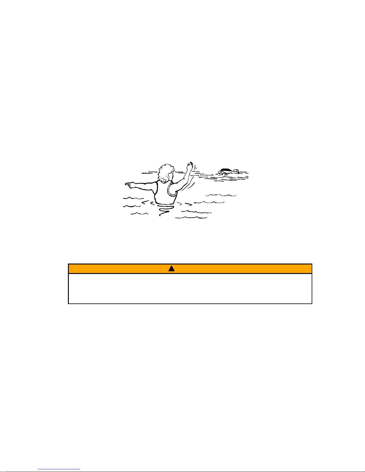
WHILE YOU ARE TROLLING
It is very difficult for a person in the water to take quick action to avoid a boat
heading in their direction, even at slow speeds.
21604
Always slow down and exercise extreme caution any time you are boating in an
area where there might be people in the water.
WHILE THE BOAT IS STATIONARY
!
WARNING
A spinning propeller, a moving boat, or any solid device attached to the boat
can cause serious injury or death to swimmers. Stop the trolling motor
immediately whenever anyone in the water is near your boat.
Shut off the trolling motor before allowing people to swim or be in the water
near your boat.
Passenger Safety Message
Whenever the boat is in motion, observe the location of all passengers. A
sudden reduction in boat speed, such as a sharp change of boat direction,
could throw them off the boat.
Safe Boating Suggestions
In order to safely enjoy the waterways, familiarize yourself with local and other
governmental boating regulations and restrictions, and consider the following
suggestions.
Use flotation devices. It is the law to have an approved personal flotation
device of suitable size for each person aboard and have it readily accessible.
GENERAL INFORMATION
eng 3
Page 8

Do not overload your boat. Most boats are rated and certified for maximum
load (weight) capacities, refer to your boat capacity plate. If in doubt, contact
your dealer or the boat's manufacturer.
Perform safety checks and required maintenance. Follow a regular
schedule and ensure all repairs are made properly.
Never be under the influence of alcohol or drugs while boating (it is the
law). Alcohol or drug use impairs your judgment and greatly reduces your
ability to react quickly.
Passenger boarding. Stop the trolling motor whenever passengers are
boarding or unloading.
Be alert. The operator of the boat is responsible by law to maintain a proper
lookout by sight and hearing. The operator must have an unobstructed view
particularly to the front. No passengers, load, or fishing seats should block the
operators view when operating the boat.
Underwater hazards. Reduce speed and proceed with caution whenever
navigating in shallow water.
Tripping hazards. To avoid a trip hazard, route all cables and wiring neatly
and out of the way.
Report accidents. Boat operators are required by law to file a Boating
Accident Report with their state boating law enforcement agency when their
boat is involved in certain boating accidents. A boating accident must be
reported if 1) there is loss of life or probable loss of life, 2) there is personal
injury requiring medical treatment beyond first aid, 3) there is damage to boats
or other property where the damage value exceeds $500.00 or 4) there is
complete loss of the boat. Seek further assistance from local law enforcement.
GENERAL INFORMATION
4 eng
Page 9
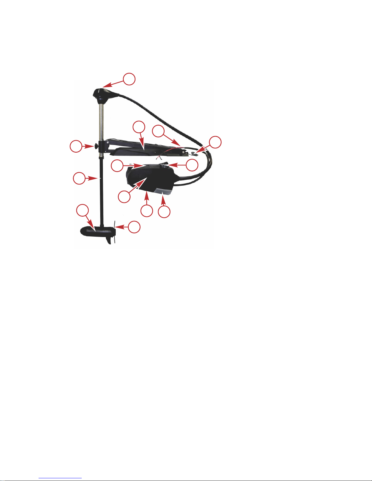
X3‑40/X3‑45/X3‑55/X3‑70 MotorGuide Trolling Motor
CABLE STEER MODELS
a - Directional indicator
b - Mount bracket
c - Battery cables
d - Latch release handle
e - Speed control
f - Three‑position switch
g - Foot pedal
h - Serial number decal
(under the foot pedal)
i - Momentary switch
j - Propeller
k - Lower unit
l - Composite column
m - Bracket door knob
a
h
b
c
d
e
f
g
i
j
k
l
m
54509
PRODUCT OVERVIEW
eng 5
Page 10
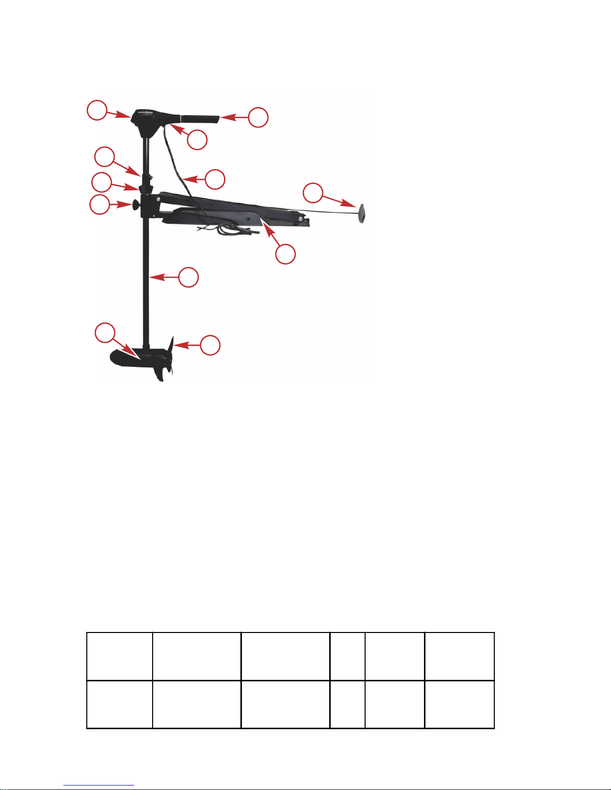
HAND-OPERATED MODELS
a - Top housing
b - Extendable speed control tiller handle
c - Serial number decal
d - Battery cables
e - Latch release handle
f - Mount bracket
g - Composite column
h - Propeller
i - Lower unit
j - Bracket door knob
k - Steering tension collar
l - Depth adjustment collar
Specifications
Model
Peak Thrust Shaft
Volt
s
Speeds
Forward/
Reverse
Control
X3‑45 FW
20.4 kgf
(45 lbf)
127.0 cm
(50 in.)
12 V 5/2
Extendable
Hand/
Twist‑Tiller
54512
a
b
c
d
e
f
g
h
i
j
k
l
PRODUCT OVERVIEW
6 eng
Page 11

Model Peak Thrust Shaft
Volt
s
Speeds
Forward/
Reverse
Control
X3‑55 FW
24.9 kgf
(55 lbf)
127.0 cm
(50 in.)
12 V 5/2
Extendable
Hand/
Twist‑Tiller
X3‑40 FW
18.1 kgf
(40 lbf)
106.7 cm
(42 in.)
12 V 5
Foot Pedal/
Cable
Steer
X3‑45 FW
20.4 kgf
(45 lbf)
91.4 cm
(36 in.)
12 V 5
Foot Pedal/
Cable
Steer
X3‑45 FW
20.4 kgf
(45 lbf)
114.3 cm
(45 in.)
12 V 5
Foot Pedal/
Cable
Steer
X3‑45 FW
20.4 kgf
(45 lbf)
127.0 cm
(50 in.)
12 V 5
Foot Pedal/
Cable
Steer
X3‑55 FW
24.9 kgf
(55 lbf)
91.4 cm
(36 in.)
12 V 5
Foot Pedal/
Cable
Steer
X3‑55 FW
24.9 kgf
(55 lbf)
106.7 cm
(42 in.)
12 V 5
Foot Pedal/
Cable
Steer
X3‑55 FW
24.9 kgf
(55 lbf)
114.3 cm
(45 in.)
12 V 5
Foot Pedal/
Cable
Steer
X3‑55 FW
24.9 kgf
(55 lbf)
127.0 cm
(50 in.)
12 V 5
Foot Pedal/
Cable
Steer
X3‑70 FW
31.8 kgf
(70 lbf)
114.3 cm
(45 in.)
24 V 5
Foot Pedal/
Cable
Steer
X3‑70 FW
31.8 kgf
(70 lbf)
127.0 cm
(50 in.)
24 V 5
Foot Pedal/
Cable
Steer
PRODUCT OVERVIEW
eng 7
Page 12

Wiring and Battery Information
!
WARNING
An operating or charging battery produces gas that can ignite and explode,
spraying out sulfuric acid, which can cause severe burns. Ventilate the area
around the battery and wear protective equipment when handling or servicing
batteries.
!
WARNING
Performing service or maintenance without first disconnecting the battery can
cause product damage, personal injury, or death due to fire, explosion,
electrical shock, or unexpected motor starting. Always disconnect the battery
cables from the battery before maintaining, servicing, installing, or removing
motor components.
Standard Practices and Procedures
When installing or removing this trolling motor, follow these guidelines:
• Disconnect the trolling motor from the trolling motor battery.
• Do not use the main engine battery to power the trolling motor.
Battery Recommendations
• Use a 12‑volt, deep cycle marine battery.
• Install a manual reset circuit breaker in line with the trolling motor positive
(+) leads within 180 cm (72 in.) of the batteries.
• If extending the existing wire beyond the standard battery cable, use
13 mm² (6‑gauge) battery cables.
Recommended MotorGuide Accessory Description
Part Number
6‑gauge battery cable and terminals with 50‑amp
manual reset circuit breaker
MM309922T
50‑amp manual reset circuit breaker MM5870
60‑amp manual reset circuit breaker 8M0064076
Battery Precautions
!
WARNING
An operating or charging battery produces gas that can ignite and explode,
spraying out sulfuric acid, which can cause severe burns. Ventilate the area
around the battery and wear protective equipment when handling or servicing
batteries.
WIRING AND BATTERY INFORMATION
8 eng
Page 13

When charging batteries, an explosive gas mixture forms in each cell. Part of
this gas escapes through holes in the vent plugs and may form an explosive
atmosphere around the battery if ventilation is poor. This explosive gas may
remain in or around the battery for several hours after it has been charged.
Sparks or flames can ignite this gas and cause an internal explosion, which
may shatter the battery.
The following precautions should be observed to prevent an explosion:
1. Do not smoke near batteries being charged or which have been charged
very recently.
2. Do not break live circuits at terminals of batteries, because a spark
usually occurs at the point where a live circuit is broken. Always be careful
when connecting or disconnecting cable clamps on chargers. Poor
connections are a common cause of electrical arcs which cause
explosions.
3. Do not reverse polarity of battery terminal to cable connections.
Wire and Cable Routing
• Route the trolling motor wires on the opposite side of the boat from other
boat wiring.
• The trolling motor should be connected to its own dedicated battery.
• Sensitive electronics, such as depth finders, should be connected to a
separate battery.
• Marine engines should have their own dedicated starting battery.
• All batteries should have a common ground.
WIRING AND BATTERY INFORMATION
eng 9
Page 14

Wire Color Code Abbreviations
Wire Color Abbreviations
BLK Black
BLU Blue
BRN Brown GRY Gray
GRN Green ORN or ORG Orange
PNK Pink PPL or PUR Purple
RED Red TAN Tan
WHT White YEL Yellow
LT or LIT Light DK or DRK Dark
WIRING AND BATTERY INFORMATION
10 eng
Page 15

Battery Connection
!
CAUTION
Disconnecting or connecting the battery cables in the incorrect order can
cause injury from electrical shock or can damage the electrical system.
Always disconnect the negative (‑) battery cable first and connect it last.
12-VOLT BATTERY CONNECTION
1. Install a 50‑amp (good) or 60‑amp (best) manual reset circuit breaker in
line with the trolling motor power cable positive (+) lead and the battery
positive (+) terminal. Connect the trolling motor positive lead to the trolling
motor battery positive (+) terminal.
2. Connect the black trolling motor power cable negative (–) lead to the
trolling motor battery negative (–) terminal.
3. Connect a common ground bond from the trolling motor battery negative
(–) terminal to the engine starting battery negative (–) terminal.
a - Power cables to trolling motor
b - Manual reset circuit breaker
c - Trolling motor battery
d - Engine starting battery
e - Power cables to engine
f - Common ground bond
24-VOLT BATTERY CONNECTION
1. Install a 50‑amp (good) or 60‑amp (best) manual reset circuit breaker in
line with the trolling motor power cable positive (+) lead and the trolling
motor battery B positive (+) terminal.
2. Connect the positive (+) trolling motor lead to the positive (+) terminal on
trolling motor battery B.
3. Connect a jumper wire (reference gray) between the negative (–) terminal
on battery B to the positive (+) terminal on battery A.
RED
BLK
BLK
REDRED
abc
e
f
d
45086
WIRING AND BATTERY INFORMATION
eng 11
Page 16

IMPORTANT: The jumper wire should be the same wire gauge as the
negative (–) and positive (+) power cables.
4. Connect the trolling motor negative (–) lead to the negative (–) terminal on
battery A.
5. Starting with the positive (+) lead, reconnect the battery cables to the
engine starting battery.
a - Power cables to trolling motor
b - Manual reset circuit breaker
c - Jumper wire (not supplied)
d - Negative (–) battery terminal
RED
BLK
a
b
c
d
37824
GRY
c
Battery A
Battery B
WIRING AND BATTERY INFORMATION
12 eng
Page 17

Mount Bracket Installation
a - X3 bow mount bracket
b - Latch release handle
c - Bracket door knob
IMPORTANT: Choose an area on the boat deck that allows a 7.6 cm (3 in.)
clearance between the bow of the boat and the column of the trolling motor.
1. Select an appropriate area on the deck of the boat to install the mount.
Ensure that the forward mounting screws will not penetrate the hull.
a - Clearance 7.6 cm (3.0 in.)
2. Place the bow mount base on the surface of the boat deck. Use the
mount base as a template to mark the locations of the front mounting
holes and the rear mounting holes on the mount base.
a
b
c
54513
54514
a
a
TROLLING MOTOR INSTALLATION AND OPERATION
eng 13
Page 18

IMPORTANT: A minimum of four mounting bolts are required to mount the
trolling motor to the boat. Spread the mounting bolts as far apart as practical
for the most secure mounting.
a - Mount bracket
mounting holes
3. Drill the mounting holes with a 7 mm (1/4 in.) diameter drill bit. Remove
any debris.
IMPORTANT: Using a larger drill bit, countersink the holes on fiberglass boats
to prevent cracking.
4. Insert the rubber isolators between the base of the mount and the boat
mounting surface. Place the tie‑down strap under the mount bracket,
hook‑and‑loop side down, with the buckle facing toward the outside of the
boat.
NOTE: If the trolling motor is being mounted to a carpeted boat deck, the
rubber isolators are not required.
a - Velcro tie‑down strap
b - Buckle
5. Install the steel washers and nylon locking nuts onto the mounting bolts
underneath the boat deck. Tighten them securely with (7/16 in.)
wrenches.
54516
a
a
a
a
a
a
b
a
54586
TROLLING MOTOR INSTALLATION AND OPERATION
14 eng
Page 19

IMPORTANT: If necessary, shim the rubber washers with 25 mm (1 in.)
outside diameter stainless steel washers to create a level mounting surface.
a - Mount bracket
b - Mounting bolt
c - Rubber isolator
d - Deck
e - Washer
f - Nylon locking nut
g - Carpet
6. Once installed, the bracket should fasten securely and evenly, with the
latch pins in the slots, and release with a light, easy pull on the rope
handle.
Permanent Foot Pedal Mounting (Optional)
1. Determine a suitable location for the foot pedal with the trolling motor
deployed and in the stowed position. Ensure that there are no
obstructions beneath the boat deck that would interfere with the mounting
screws, such as bulkheads or boat wiring.
2. Once a suitable location is chosen, mark the mounting holes, using the
foot pedal as a template.
3. Use a 3 mm (7/64 in.) drill bit to drill holes through the boat deck.
a
b
c
d
e
f
a
b
d
e
f
g
52406
TROLLING MOTOR INSTALLATION AND OPERATION
eng 15
Page 20

4. Use four #8 x 2 in. stainless steel screws to secure the foot pedal to the
boat deck.
54589
Installing the Motor into the Bow Mount
a - Steering tension collar
(hand‑operated models only)
b - Bracket door
c - Bracket door knob
1. Turn the bracket door knob counterclockwise to loosen and open the
bracket door.
2. Place the motor column into the bracket and close the door.
3. Turn the bracket door knob clockwise to tighten the motor column in the
bracket.
Removing the Motor from the Bow Mount
1. Turn the bracket door knob counterclockwise to loosen and open the
bracket door.
2. Remove the motor column from the bracket and close the door.
a
b
c
54517
TROLLING MOTOR INSTALLATION AND OPERATION
16 eng
Page 21

Stowing the Trolling Motor
!
WARNING
Rotating propellers can cause serious injury or death. Never start or operate
the motor out of water.
!
CAUTION
Moving parts, such as hinges and pivot points, can cause serious injury.
Keep away from moving parts when stowing, deploying, or tilting the motor.
1. Firmly grasp the latch release handle.
2. Snap the latch release handle to disengage the lock pin.
3. Continue to pull the latch release handle to raise the lower unit onto the
mount.
NOTE: Hand‑operated trolling motor shown in the illustration below.
a - Latch release handle
IMPORTANT: Gently raise the trolling motor out of the water. Do not release
the latch release handle until the lock pin is engaged.
a
54519
TROLLING MOTOR INSTALLATION AND OPERATION
eng 17
Page 22

4. Once the motor is in the stowed position, the lock pin engages to secure
the trolling motor.
a - X3 in the stowed position
5. Position the tie‑down strap over the composite column and through the
buckle. Pull it tight, then secure the hook‑and‑loop backing together to
secure the motor to the mount bracket.
a - Tie‑down strap
Deploying the Trolling Motor
!
WARNING
Rotating propellers can cause serious injury or death. Never start or operate
the motor out of water.
!
CAUTION
Moving parts, such as hinges and pivot points, can cause serious injury.
Keep away from moving parts when stowing, deploying, or tilting the motor.
!
CAUTION
Avoid possible serious injury from the motor dropping suddenly when
adjusting the motor depth. Firmly grasp the motor shaft with one hand when
raising or lowering the motor.
1. Remove the tie‑down strap securing the trolling motor to the mount
bracket.
2. Firmly grasp the latch release handle.
a
54520
a
54587
TROLLING MOTOR INSTALLATION AND OPERATION
18 eng
Page 23

3. Snap the latch release handle to disengage the lock pin.
4. Continue to maintain tension on the latch release handle while lowering
the trolling motor into the water.
IMPORTANT: Gently lower the trolling motor into the water. Do not release the
latch release handle until the lock pin is engaged.
a - Latch release handle
5. Once the motor is in the deployed position, the lock pin will engage to
secure the trolling motor.
a - X3 in the deployed position
Adjusting the Steering Tension (Hand‑Operated Motors Only)
Adjust the steering tension collar to increase or decrease the effort to turn the
motor freely.
1. To increase the steering tension, turn the steering tension collar
clockwise.
a
54519
a
54521
TROLLING MOTOR INSTALLATION AND OPERATION
eng 19
Page 24

2. To reduce the steering tension, turn the steering tension collar
counterclockwise.
a - Steering tension collar
Adjusting the Motor Depth
!
CAUTION
Avoid possible serious injury from dropping the motor when adjusting the
motor depth. Firmly grasp the motor shaft with one hand when raising or
lowering the motor.
HAND-OPERATED MODELS
Adjust the depth of the motor to improve trolling motor performance in various
water depths.
IMPORTANT: When adjusting the motor depth, ensure that the propeller
blades are fully submerged 15–30 cm (6–12 in.) below the water surface to
avoid ventilation.
1. Firmly grasp the column with one hand while holding the depth
adjustment collar.
2. Loosen the depth adjustment collar until the motor column slides freely.
3. Raise or lower the motor column until the propeller blades are submerged
15–30 cm (6–12 in.) below the water surface, then tighten the collar.
a - Depth adjustment collar
a
54522
a
54523
TROLLING MOTOR INSTALLATION AND OPERATION
20 eng
Page 25

CABLE STEER MODELS
IMPORTANT: When adjusting the motor depth, ensure that the propeller
blades are fully submerged 15–30 cm (6–12 in.) below the water surface to
avoid ventilation.
1. Firmly grasp the column with one hand.
2. Loosen the bracket door knob until the motor column slides freely.
3. Raise or lower the motor column until the propeller blades are submerged
15–30 cm (6–12 in.) below the water surface, then tighten the collar.
a - Bracket door knob
54573
a
TROLLING MOTOR INSTALLATION AND OPERATION
eng 21
Page 26

Directional Indicator—Cable Steer Models
The indicator provides directional information at a glance.
a - Directional indicator
b - Right turn ‑ toe down; motor steers boat to right (continue to press all
the way down for reverse)
c - Straight ahead ‑ foot pedal in middle
d - Left turn ‑ heel down; motor steers boat to left (continue to press all the
way down for reverse)
54533
c
b
a
d
TROLLING MOTOR INSTALLATION AND OPERATION
22 eng
Page 27
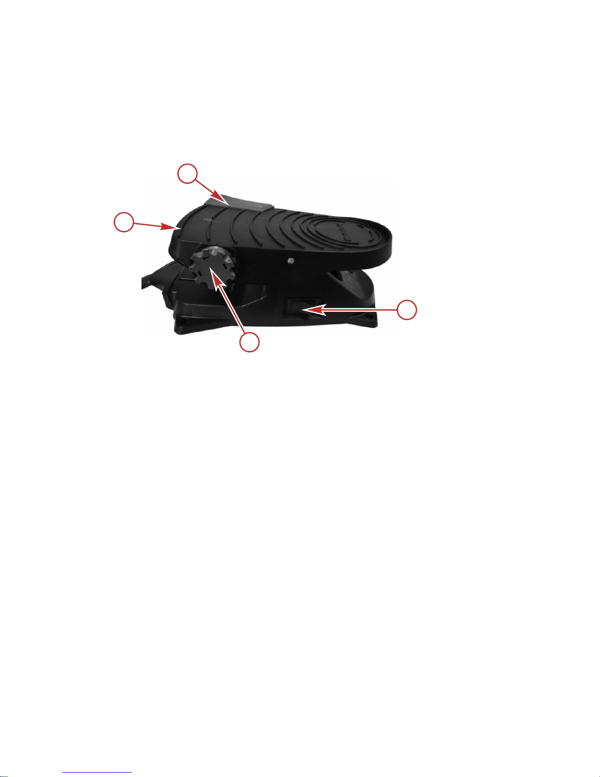
Speed Control—Cable Steer Models
FIVE-SPEED AND VARIABLE SPEED MOTORS
Foot operated motors are five‑speed models. Control the speed of your motor
by rolling the speed control knob with your hand or foot until you reach the
desired speed.
a - Foot pedal
b - Momentary switch
c - On/off/pedal switch
d - Speed control knob
•
Speed control knob: The speed control knob on a five‑speed motor is
numbered 0–5, and allows you to select one of five preset speeds, and
stop the motor.
•
Momentary switch: The momentary switch is located on the top right
corner of the foot pedal. The momentary switch works in conjunction with
the on/off/pedal switch when it is in the pedal position. When the
momentary switch is pressed, the motor will run at the selected speed as
long as the switch is pressed.
•
On/off/pedal switch: This three‑position switch provides three options for
operating the motor: on, pedal, or off.
a.
On: Allows the motor to run continuously at the speed selected by the
speed control knob, without the use of the momentary switch.
b.
Pedal: Allows the motor to activate with the momentary switch at the
speed selected by the speed control knob.
c.
Off: Turns the trolling motor off.
a
b
c
d
54534
TROLLING MOTOR INSTALLATION AND OPERATION
eng 23
Page 28
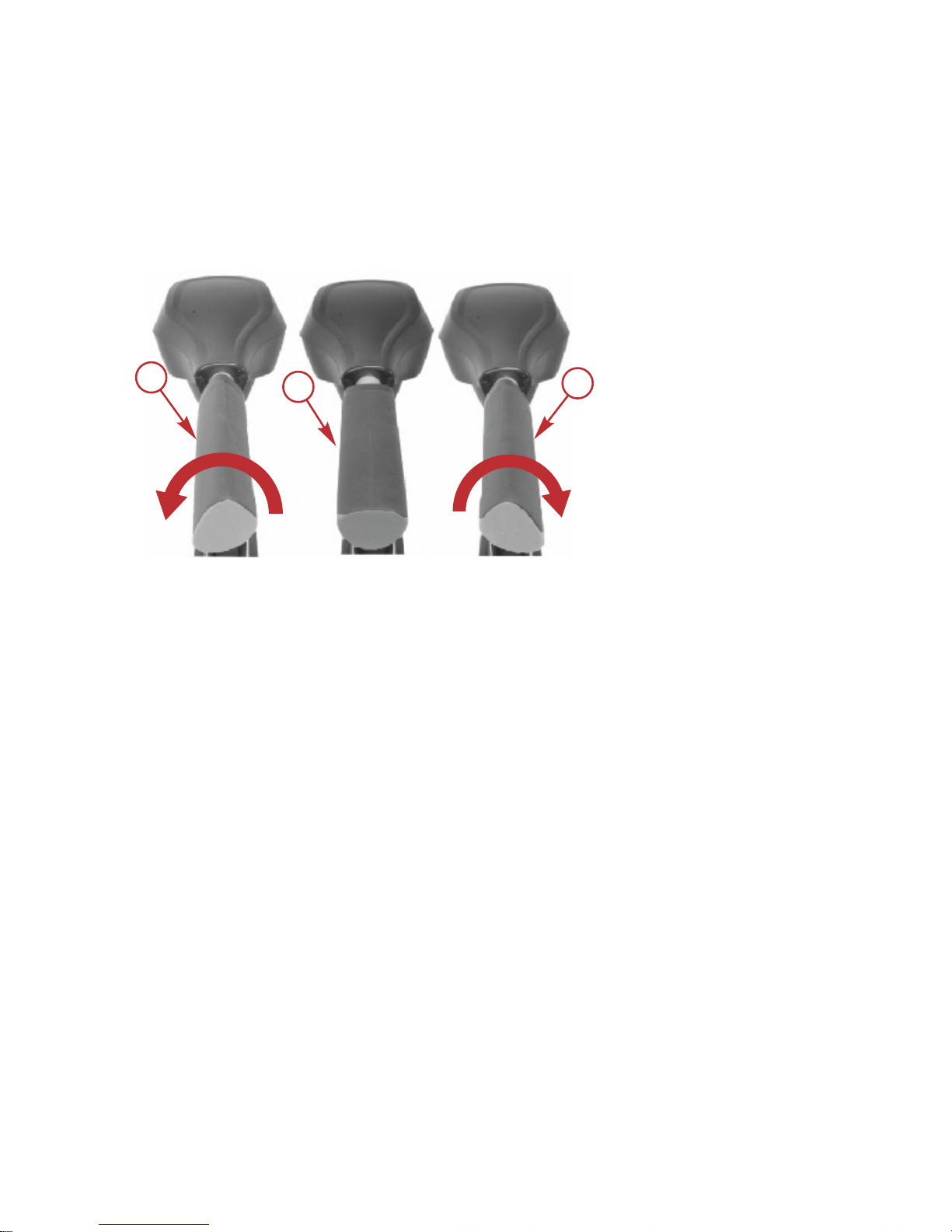
Speed Control
Adjust the speed control (five forward speeds and two reverse speeds) to the
desired direction and thrust level.
Rotate the twist‑tiller handle clockwise for forward movement and
counterclockwise for reverse movement. The "off" handle position stops the
motor.
a - Forward speed control (five speeds clockwise)
b - Off
c - Reverse speed control (two speeds counterclockwise)
b
45750
c
a
TROLLING MOTOR INSTALLATION AND OPERATION
24 eng
Page 29

Trolling Motor Care
To keep your trolling motor in the best operating condition and retain its
dependability, it is important that your trolling motor receive periodic inspections
and maintenance. We urge you to keep it maintained properly to ensure the
safety of you and your passengers.
!
WARNING
Neglecting to inspect, maintain, or repair your trolling motor can result in
product damage or serious injury or death. Do not perform maintenance or
service on your trolling motor if you are not familiar with the correct service
and safety procedures.
SELECTING REPLACEMENT PARTS
We recommend using original MotorGuide Certified Tough replacement parts.
Inspection and Maintenance Schedule
BEFORE EACH USE
• Check the trolling motor for tightness on the deck mount.
• Check the tightness of the battery lead connections.
• Visually inspect for loose or corroded wiring connections.
• Check the tightness of the propeller nut.
• Check the propeller blades for damage.
AFTER EACH USE
• Disconnect the battery cables from the power source.
• Check the propeller and the propeller shaft for debris such as weeds and
fishing line. Remove all debris.
• Rinse the trolling motor with clean water to remove dirt and dust that may
scratch the surface.
EVERY 100 HOURS OF USE OR ANNUALLY
•
Periodically lubricate all the pivot points. Refer to Lubrication Points.
• Check the tightness of bolts, nuts, and other fasteners.
•
Inspect the battery. Refer to Battery Inspection.
STORAGE PREPARATION
The major consideration in preparing the trolling motor for storage is to protect
it from corrosion and damage caused by freezing of trapped water.
Complete the appropriate care instructions to prepare the trolling motor for
storage. Store the trolling motor in a dry location where it will not be affected by
temperatures below ‑29 °C (‑20 °F).
MAINTENANCE
eng 25
Page 30
IMPORTANT: Trolling motors stored in temperatures below 0 °C (32 °F) should
be operated slowly for a minimum of 15 minutes before going above 30%
operation.
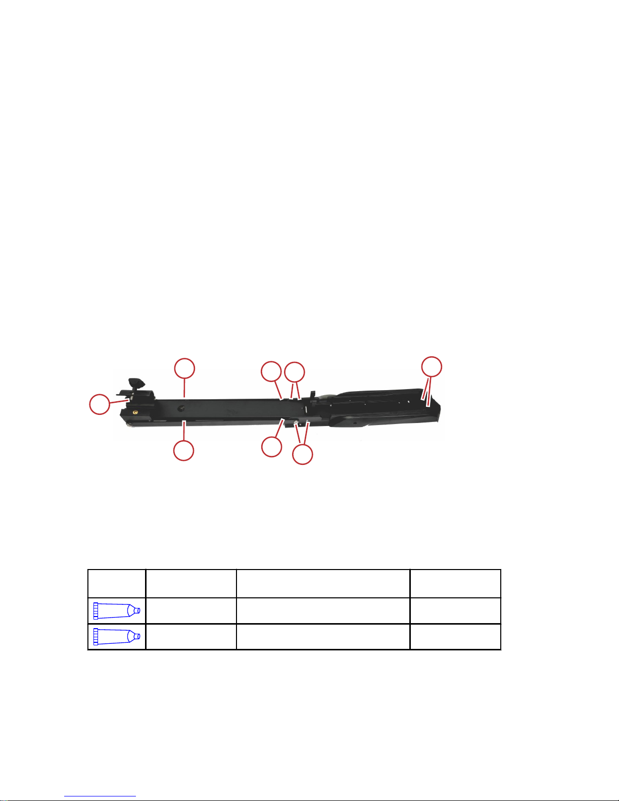
Lubrication Points
NOTE: Preferred lubricants can be obtained at any authorized MotorGuide or
Mercury Marine service center.
To reduce friction and quiet squeaks, lubricate the specified locations
periodically with the following lubricants:
• Bracket door knob threads ‑ 2‑4‑C with PTFE
• Latch pin hooks ‑ 2‑4‑C with PTFE
• Latch pins ‑ 2‑4‑C with PTFE
• Pivot pins ‑ 4‑Stroke 10W‑30 Outboard Oil
IMPORTANT: Never use an aerosol lubricant to grease or oil any part of the
unit. Many aerosol lubricants contain harmful propellants that can cause
damage to various parts of the trolling motor.
IMPORTANT: Do not allow any lubricant to contact the column sleeves in the
door bracket halves as trolling motor steering tension will be affected.
a - Latch pin hooks
b - Pivot pins
c - Bracket door knob threads
d - Latch pins
Tube Ref
No.
Description Where Used Part No.
95
2-4-C with PTFE
Latch pins, latch pin hooks, and bracket
door knob threads
92-802859A 1
110
4-Stroke 10W-30
Outboard Oil
Pivot pins 92-858045K01
Battery Inspection
The battery should be inspected at periodic intervals to ensure proper trolling
motor operation.
a
a
bb
b
b
d
54524
c
c
c
c
MAINTENANCE
26 eng
Page 31

IMPORTANT: Read the safety and maintenance instructions which accompany
your battery.
1. Ensure that the battery is secured to the vessel.
2. Ensure that the battery cable terminals are clean, tight, and correctly
installed. For installation instructions, refer to Battery Connection.
3. Ensure that the battery is equipped with a battery box to prevent
accidental shorting of the battery terminals.
Propeller Replacement
!
WARNING
Performing service or maintenance without first disconnecting the battery can
cause product damage, personal injury, or death due to fire, explosion,
electrical shock, or unexpected motor starting. Always disconnect the battery
cables from the battery before maintaining, servicing, installing, or removing
motor components.
REMOVING THE PROPELLER
1. Disconnect the power cables from the battery.
2. While holding the propeller blade with one gloved hand, use a 9/16 in.
wrench or a ratchet and a 9/16 in. socket to remove the propeller nut.
Remove the propeller nut and washer (or anode, for saltwater models).
IMPORTANT: Remove the propeller nut with a wrench or a ratchet and socket.
Using another tool may damage the propeller nut or shaft. If the propeller
cannot be removed easily, use a rubber mallet to lightly tap the back side of
the opposite blade. If the propeller cannot be removed, have the propeller
removed by an authorized dealer.
MAINTENANCE
eng 27
Page 32

NOTE: If the propeller pin is bent, replace the propeller pin.
53442
44663
INSTALLING THE PROPELLER
1. Rotate the motor shaft to insert the propeller pin horizontally.
a - Propeller pin
2. Install the propeller onto the motor shaft by engaging the propeller onto
the propeller pin.
44663
a
44664
MAINTENANCE
28 eng
Page 33

3. Install the washer (or anode, for saltwater models) onto the propeller shaft
then install the propeller nut. Tighten the propeller nut securely.
53442
4. Tighten the propeller nut another ¼ turn.
Adjusting the Steering Cable Tension
!
WARNING
Neglecting to inspect, maintain, or repair your trolling motor can result in
product damage or serious injury or death. Do not perform maintenance or
service on your trolling motor if you are not familiar with the correct service
and safety procedures.
The cable tension on the X3 trolling motor is preset at the factory. With time
and use, the cables may stretch slightly, requiring occasional adjustment. The
following procedure explains how to adjust the steering cable tension.
Use care while adjusting the steering cable tension. Excessive cable tension
will cause premature wear to the cables and pulleys, while excessively loose
tension may cause the cables to jump off of the pulleys, resulting in a loss of
steering control.
1. Remove the foot pedal from the boat deck if it has been secured with
screws.
2. Adjust the cable tension by turning the cable tension screw clockwise to
increase tension, and counterclockwise to decrease tension.
Bottom of foot pedal
a - Cable tension screw
a
54574
MAINTENANCE
eng 29
Page 34

MotorGuide Accessories Inquiries
Refer to www.motorguide.com for factory authorized accessories for all
MotorGuide trolling motors.
MAINTENANCE
30 eng
Page 35

Trolling Motor Performance
Symptom Possible Cause Resolution
Loss of power
Weak battery
Refer to Wiring and Battery
Information.
Loose or corroded battery
connections
Propeller is loose,
damaged, or off‑balance
Refer to Maintenance.
Wiring or electrical
connection faulty
Wire gauge from the battery
to the trolling motor is
insufficient. Six‑gauge wire
(13 mm²) is recommended.
Weeds, fishing line, or
debris wrapped around
propeller
Remove weeds, fishing line,
or debris from propeller.
Excessive noise,
vibration
Motor shaft is bent
Refer to Warranty
Information.
Propeller is loose,
damaged, or off‑balance
Refer to Maintenance.
Motor failure (all
speeds)
Weak battery
Refer to Wiring and Battery
Information.
Loose or corroded battery
connections
Electrical
Check the connector for a
loose or damaged
connection. Refer to Wiring
and Battery Information.
Fuse or circuit breaker is
open
Locate and correct the cause
of the overload. Then
replace the fuse or reset the
circuit breaker.
Motor failure (one
or more speeds)
Propeller is loose,
damaged, or off‑balance
Refer to Maintenance.
Wiring or electrical
connection faulty.
Refer to Warranty
Information.
TROUBLESHOOTING
eng 31
Page 36

Symptom Possible Cause Resolution
Difficulty removing
propeller
Bent propeller pin
Hold one blade and lightly
tap the opposite blade with a
rubber mallet.
Use a putty knife on both
sides of the propeller to
apply equal pressure.
Bent armature shaft Refer to service center.
Mount bracket
squeaks
Lock pins need
lubrication
Lubricate the lock pins on
the mount bracket with 2‑4‑C
with PTFE.
TROUBLESHOOTING
32 eng
Page 37

Mercury Marine Service Offices
For assistance, call, fax, or write. Please include your daytime telephone
number with mail and fax correspondence.
United States, Canada
Telephone
English ‑ (920) 929‑5040
Français ‑ (905) 636‑4751
Mercury Marine
W6250 W. Pioneer Road
P.O. Box 1939
Fond du Lac, WI 54936-1939
Fax
English ‑ (920) 929‑5893
Français ‑ (905) 636‑1704
Website www.mercurymarine.com
Australia, Pacific
Telephone (61) (3) 9791‑5822 Brunswick Asia Pacific Group
41–71 Bessemer Drive
Dandenong South, Victoria 3175
Australia
Fax (61) (3) 9706‑7228
Europe, Middle East, Africa
Telephone (32) (87) 32 • 32 • 11 Brunswick Marine Europe
Parc Industriel de Petit-Rechain
B-4800 Verviers,
Belgium
Fax (32) (87) 31 • 19 • 65
Mexico, Central America, South America, Caribbean
Telephone (954) 744‑3500 Mercury Marine
11650 Interchange Circle North
Miramar, FL 33025
U.S.A.
Fax (954) 744‑3535
Japan
Telephone 072‑233‑8888 Kisaka Co., Ltd.
4-130 Kannabecho Sakai-shi Sakai-ku
5900984 Osaka,
Japan
Fax 072‑233‑8833
Asia, Singapore
Telephone (65) 65466160 Brunswick Asia Pacific Group
T/A Mercury Marine Singapore Pte Ltd
29 Loyang Drive
Singapore, 508944
Fax (65) 65467789
OWNER SERVICE ASSISTANCE
eng 33
 Loading...