

Page 1
Page 2

Page 3

Table of Contents
Introductory Information ............... 1
Safety Restraints ................... 9
Starting Your Villager .................57
Warning Lights and Gauges ..............67
Instrument Panel Controls ............... 89
Steering Column Controls .............. 123
Features ...................... 135
Adjustable Rear Seating ............... 175
Electronic Sound Systems .............. 205
Driving Your Villager ................ 229
Roadside Emergencies ................ 255
Customer Assistance ................ 275
Reporting Safety Defects ............. 281
Accessories ..................... 287
Servicing Your Villager ............... 295
Quick Index .................... 375
Index........................ 385
Service Station Information ............. 404
Page 4

Introductory Information
To fully appreciate all of the features and options of your new
vehicle, we recommend that you thoroughly read through this
guide now and refer back to it when you have specific needs or
questions. For your own safety and the safety of your
passengers, it is important that you completely understand all
performance and care procedures before operating this vehicle.
For example, without reading further, would you know:
■ What to do if you get a flat tire? (Refer to Flat tire in the
Index)
■ What it means if the O/D OFF light is illuminated on your
instrument panel? (Refer to Overdrive in the Index)
■ How to engage the childproof safety lock on the sliding
door? (Refer to Childproof lock in the Index)
■ That your automatic transaxle will not shift out of PARK (P)
until you depress the brake pedal? (Refer to Gearshift in the
Index)
At Ford Motor Company, excellence is the continuous
commitment to achieve the best result possible. It is dedication
to learning what you want, determination to develop the right
concept, and execution of that concept with care, precision, and
attention to detail. In short, excellence means being the standard
by which others are judged.
Our Guiding Principles
■ Quality comes first. For your satisfaction, the quality of our
products and services must be our number one priority.
■ You are the focus of everything we do. Our work must be
done with you in mind, providing better products and
services than our competition.
1
Page 5

■ Continuous improvement is essential to our success. We
must strive for excellence in everything we do: in our
products — in their safety and value — and in our services,
our human relations, our competitiveness, and our
profitability.
■ Employee involvement is our way of life. We are a team.
We must treat one another with trust and respect.
■ Dealers and suppliers are our partners. We must maintain
mutually beneficial relationships with dealers, suppliers, and
our other business associates.
■ Integrity is never compromised. Our conduct worldwide
must be pursued in a manner that is socially responsible and
commands respect for its integrity and for its positive
contributions to society.
Congratulations on the purchase of your new vehicle. This
guide has information about the equipment and the options for
your new vehicle. You may not have bought all of the options
available to you. If you do not know which information applies
to your vehicle, talk to your dealer.
This guide describes equipment and gives specifications for
equipment that was in effect when this guide was approved for
printing. Ford may discontinue models or change specifications
or design without any notice and without incurring obligation.
NOTES and WARNINGS
NOTES give you additional information about the subject
matter you are referencing.
WARNINGS remind you to be especially careful in those areas
where carelessness can cause damage to your vehicle or
personal injury to yourself, your passengers or other people.
Please read all WARNINGS carefully.
2
Page 6

Introductory Information
RWARNING
Finding Information in This Guide
After you have read this guide once, you will probably return
to it when you have a specific question or need additional
information. To help you find specific information quickly, you
can use the Quick Index, Table of Contents, or the Index.
The Quick Index at the end of the book provides a page
number following each item which indicates where detailed
information can be found.
To use the Index, turn to the back of the book and search in the
alphabetical listing for the word that best describes the
information you need. If the word you chose is not listed, think
of other related words and look them up. We have designed the
Index so that you can find information under a technical term.
Canadian Owners — French Version
French Owner Guides can be obtained from your dealer or by
writing to Ford Motor Company of Canada, Limited, Service
Publications, P.O. Box 1580, Station B, Mississauga, Ontario L4Y
4G3.
As with any other member of your family, your new vehicle
requires routine care and regular check-ups. A separate
Maintenance Schedule and Record booklet is included to help you
keep track of all services performed and summarizes the
day-to-day services that are most important for keeping your
vehicle in good condition.
3
Page 7

Your vehicle is covered by three types of warranties: Basic
Vehicle Warranty, Extended Warranties on certain parts, and
Emissions Warranties.
Read your Warranty Information Booklet carefully to find out
about your vehicle’s warranties and your basic rights and
responsibilities.
If you lose your Warranty Information Booklet, you can get a new
one free of charge. Contact any Ford or Lincoln-Mercury dealer,
or refer to the addresses and phone numbers on the first page
of this owner guide.
More Protection for Your Vehicle
You can get more protection for your new car or light truck by
purchasing a Ford Extended Service Plan (Ford ESP). Ford ESP
is the only extended service program with the Ford name on it
and the only service contract backed by Ford Motor Company.
Ford ESP is an optional service contract, backed and
administered by Ford. It provides:
■ protection against repair costs after your Bumper to Bumper
Warranty expires;
and
■ other benefits during the warranty period (such as:
reimbursement for rentals; coverage for certain maintenance
and wear items).
You may purchase Ford ESP from any participating Ford Motor
Company dealer. There are several Ford ESP plans available in
various time-and-mileage combinations. Each plan can be
tailored to fit your own driving needs, including reimbursement
benefits for towing and rental. (In Hawaii, rules vary. See your
dealer for details.)
4
Page 8

Introductory Information
When you purchase Ford ESP, you receive peace-of-mind
protection throughout the United States and Canada, provided
by a network of more than 5,100 participating Ford Motor
Company dealers.
NOTE: Repairs performed outside the United States and
Canada are not eligible for ESP coverage.
This information is subject to change. Ask your dealer for
complete details about Ford ESP coverage.
Your new vehicle will go through an adjustment or break-in
period during the first 1,000 miles (1,600 km) of driving. During
the break-in period, you need to pay careful attention to how
you drive your vehicle.
■ Change your speed often as you drive. Do not drive at one
speed for a long time.
■ Use only the type of engine oil that Ford recommends. See
Engine oil recommendations in the Index. Do not use special
“break-in” oils.
■ Avoid sudden stops. Because your vehicle has new brake
linings, you should take these steps:
— Watch traffic carefully so that you can anticipate when to stop.
— Begin braking well in advance.
— Apply the brakes gradually.
The break-in period for new brake linings lasts for 100 miles
(160 km) of city driving or 1,000 miles (1,600 km) of highway
driving.
5
Page 9

Washing and Polishing Your Vehicle
Wash the outside of your vehicle, including the underside, with
a mild detergent.
DO NOT:
■ Wash your vehicle with hot water
■ Wash your vehicle while it sits in direct sunlight
■ Wash your vehicle while the body is hot
Pollen, bird droppings and tree sap can damage the paint,
especially in hot weather. Wash your vehicle as often as
necessary to keep it clean.
Take similar precautions if your vehicle is exposed to chemical
industrial fallout.
Paint damage resulting from fallout is not related to a defect in
paint materials or workmanship and therefore, is not covered by
warranty. Ford, however, believes that continual improvement
in customer satisfaction is a high priority. For this reason, Ford
has authorized their dealers to repair, at no charge to the
owner, the surfaces of new vehicles damaged by environmental
fallout within 12 months or 12,000 miles (20,000 km) of
purchase, whichever comes first. Customers may be required to
bring their vehicle in for inspection by a Ford representative.
Polish your vehicle to remove harmful deposits and protect the
finish.
6
Page 10

Introductory Information
Cleaning Chrome and Aluminum Parts
Wash chrome and aluminum parts with a mild detergent. Do
not use steel wool, abrasive cleaners, fuel or strong detergents.
Cleaning Plastic Parts
Some of your vehicle’s exterior trim parts are plastic. Clean with
a tar and road oil remover if necessary. Use a vinyl cleaner for
routine cleaning.
Do not clean plastic parts with thinners, solvents or
petroleum-based cleaners.
If you have your vehicle rustproofed, remove oversprayed
rustproofing with a tar and road oil remover. If rustproofing is
not removed from plastic and rubber parts, it can cause
deterioration.
7
Page 11

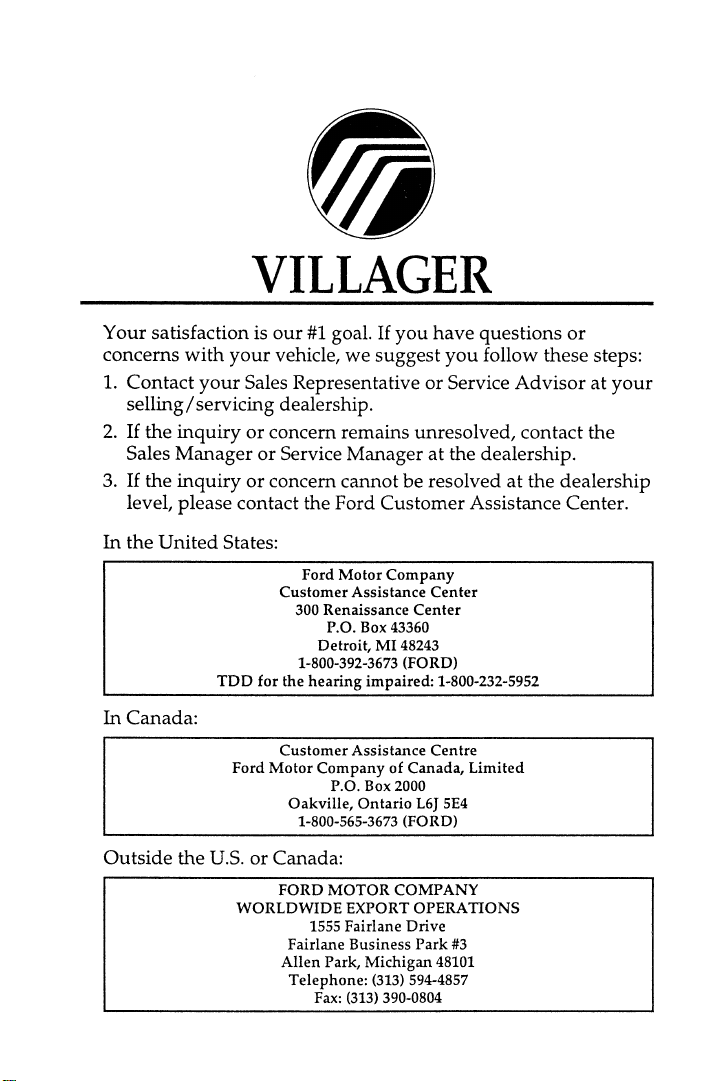
Safety Restraints
The use of safety belts helps to restrain you and your
passengers in case of a collision. In most states and in Canada
the law requires their use.
Safety belts provide best restraint when:
■ the seatback is upright
■ the occupant is sitting upright (not slouched)
■ the lap belt is snug and low on the hips
■ the shoulder belt is snug against the chest
■ the knees are straight forward
To help you remember to fasten your safety belt, a warning
light may come on and a chime may sound. See Safety Belt
Warning Light and Chime in the Warning Lights and Gauges
chapter.
See the following sections in this chapter for directions on how
to properly use these safety belts. Also see Safety Restraints for
Children in this chapter for special instructions about using
safety belts for children.
R WARNING
Make sure that you and your passengers wear safety
belts. Always drive and ride with your seatback upright
and the lap belt snug and low across the hips.
9
Page 12
R WARNING
Never wear the shoulder belt under the arm. Never
swing it around the neck over the inside shoulder. Never
use a single belt for more than one person or across more
than one seating position. Each seating position in your
vehicle has a specific safety belt assembly which is made
up of one buckle and one tongue that are designed to be
used as a pair. Failure to follow these precautions could
increase the risk and/or severity of injury in a collision.
R WARNING
Never drive or ride with a twisted or jammed safety belt.
If you cannot untwist or unjam the safety belt, see the
nearest qualified technician immediately.
R WARNING
Children should always ride with the seatback in the
fully upright position. When the seatback is not fully
upright, there is a greater risk that the child will slide
under the safety belt and be seriously injured in a
collision.
R WARNING
Never let a passenger hold a child on his or her lap
while the vehicle is moving. The passenger cannot
protect the child from injury in a collision.
R WARNING
Lock the doors of your vehicle before driving to lessen
the risk of the door coming open in a collision.
10
Page 13
Safety Restraints
While your vehicle is in motion, the combination lap and
shoulder belt adjusts to your movement. However, if you brake
hard, turn hard, or if your vehicle receives an impact of 5 mph
(8 km/h) or more, the lap and shoulder belt locks and helps to
reduce your forward movement.
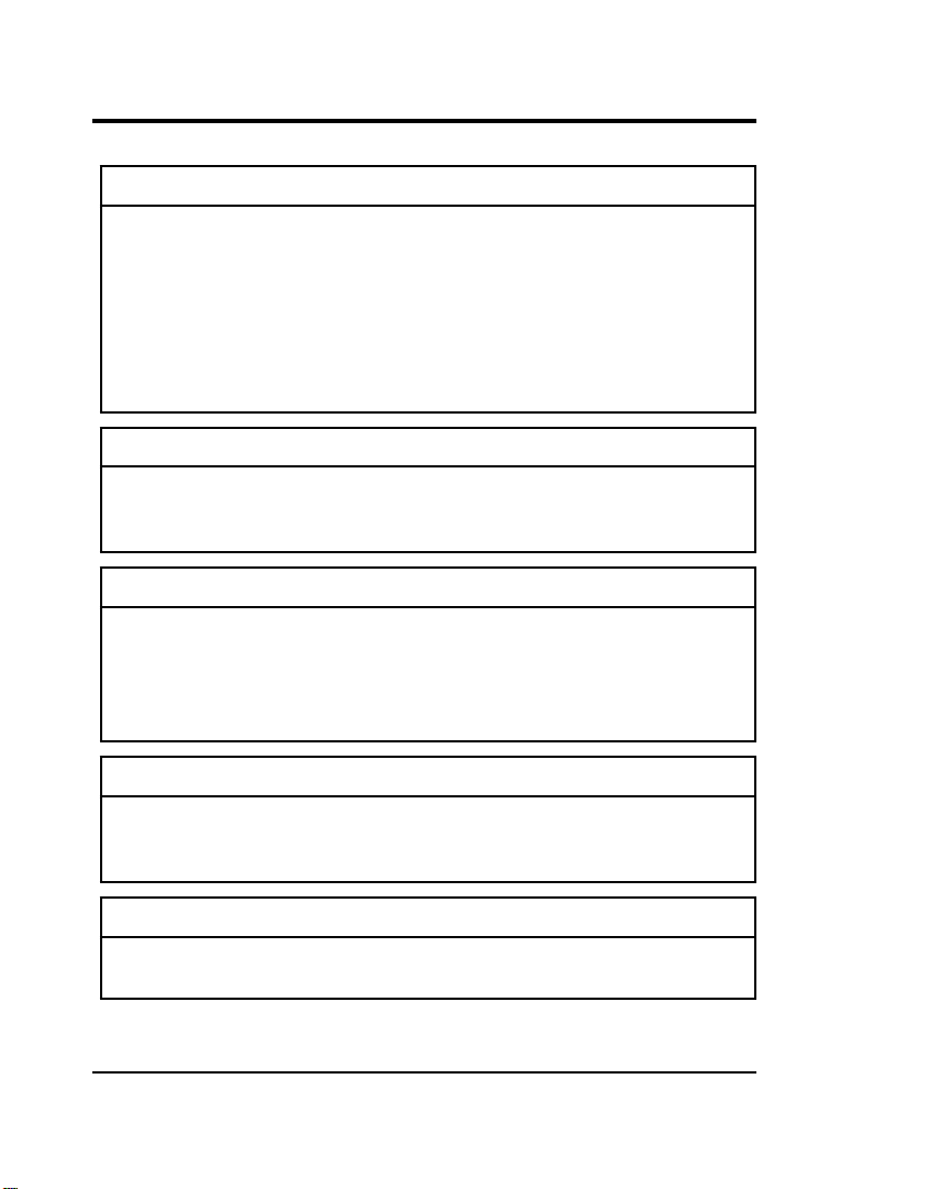
After you get into your vehicle, close the door and lock it. Then
adjust the seat to the position that suits you best.
To fasten the belt, pull the combination lap and shoulder belt
from the retractor so that the shoulder portion of the belt
crosses your shoulder and chest. Be sure the belt is not twisted.
If it is, remove the twist. Insert the belt tongue into the proper
buckle until you hear a snap and feel it latch. Make sure the
tongue is securely fastened to the buckle by pulling on tongue.
Fastening the front seat combination lap and shoulder belt
NOTE: Be sure to read and understand Important Safety Belt
Information at the beginning of this chapter.
11
Page 14
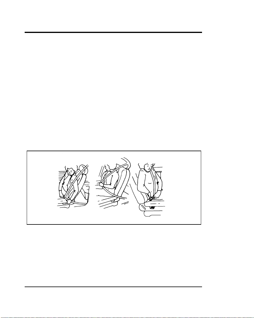
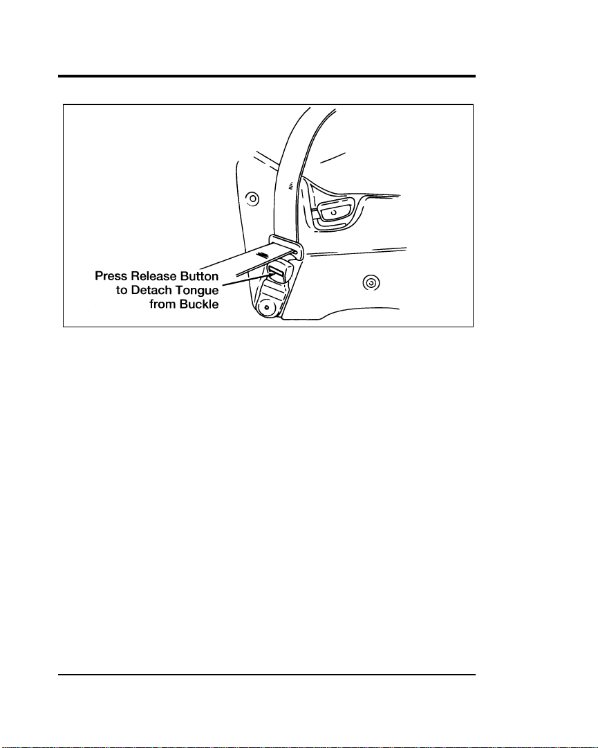
Unfastening the combination lap and shoulder belts — front and rear outboard
seating positions
Third-row passengers should be aware that the proper safety
belt for their seating position is slightly behind their seat. They
should not use the second-row safety belts which are in front of
the third seat.
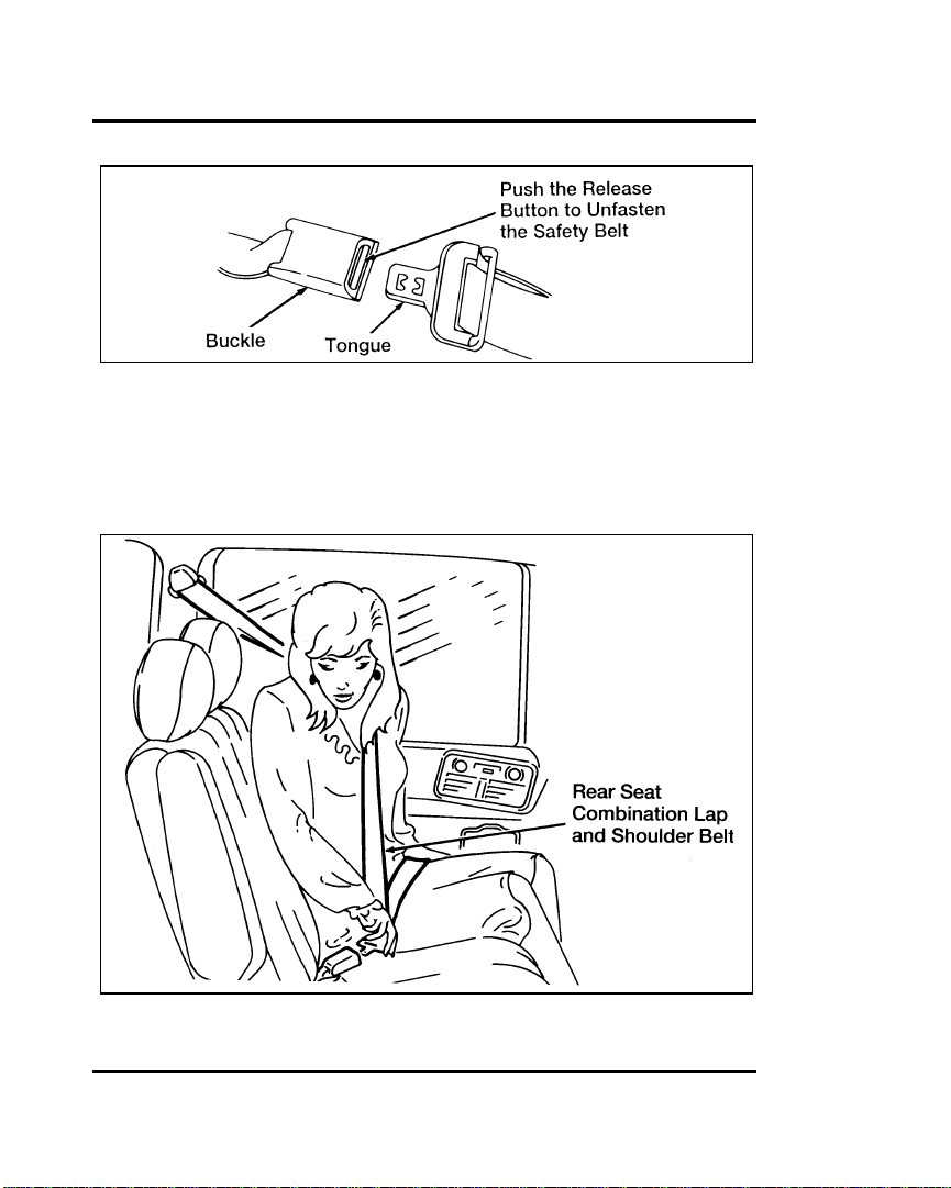
Fastening the rear seat combination lap and shoulder belt
12
Page 15

Safety Restraints
R WARNING
Use the shoulder belt on the outside shoulder only.
Never wear the shoulder belt under the arm. Never
swing it around the neck over the inside shoulder. Never
use a single belt for more than one person. Failure to
follow these precautions could increase the risk and/or
severity of injury in a collision.
To tighten the lap portion of the belt, pull up on the shoulder
belt until it fits you snugly. The belt should rest as low on your
hips as possible.
The passenger seated near the sliding door in the
three-passenger bench seat can route the safety belt webbing
under the guide located on the head restraint. This safety belt
guide is designed to help keep the safety belt webbing properly
positioned across the passenger’s chest for maximum comfort.
This guide is only needed when the two-passenger second row
bench seat is removed and the three-passenger bench seat is
moved up to the second-row position.
13
Page 16
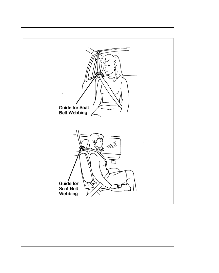
Using the seat belt guide with the three-passenger bench seat in the second row
position
14
Page 17

Safety Restraints
NOTE: The second row two-passenger bench seat has a
unique safety restraint system. If your vehicle has the
two-passenger bench seat it is very important that the
unique safety belt system is used properly. Please
read Auxiliary safety restraint system for the second
row bench seat in this section, which explains the
unique safety belt system. Be sure that you
understand it before anyone rides in the
two-passenger bench seat.
Passenger Outboard Lap/Shoulder Belts
All seats except the driver’s seat and the third seat middle
position are equipped with a dual locking mode retractor on the
shoulder belt portion of the lap/shoulder safety belt. (The
driver’s seat has only a vehicle sensitive locking mode and the
third seat middle position has a lap belt without a retractor
—description follows.)
Dual Locking Mode Retractors Operate in Two Ways:
Vehicle sensitive (emergency) locking mode
In this operating mode, the shoulder belt retractor will allow the
occupant freedom of movement, locking tight only on hard
braking, hard cornering or impacts of approximately 5 mph
(8 km/h) or more.
15
Page 18

Automatic locking mode
In this operating mode, the shoulder belt retractor will be
automatically locked and will remain locked when the
combination lap/shoulder safety belt is buckled, and does not
allow the occupant freedom of movement. This mode provides
the following:
■ A tight lap/shoulder belt on the occupant.
■ Child safety seat installation.
R WARNING
Rear-facing infant seats or infant carriers should never be
placed in the front seats.
This mode must be used when installing a child safety seat on
the front passenger seat and rear outboard seats where dual
locking retractors are provided.
To switch the retractor from the emergency locking mode to the
automatic locking mode, perform the following steps:
until all of the belt is extracted and, when allowed to retract,
a clicking sound is heard. At this time, the belt retractor is in
the automatic locking mode (child restraint mode).
allowed to retract. This indicates that the retractor is in the
automatic locking mode.
NOTE: When the combination lap/shoulder belt is unbuckled
and allowed to retract completely, the retractor will
switch to the vehicle sensitive (emergency) locking
mode. See the detailed instructions under Safety Seats
for Children in this chapter.
16
Page 19
Safety Restraints
Shoulder Belt Height Adjustment
Driver and right front passenger
You can adjust the shoulder belt height to one of five (5)
positions.
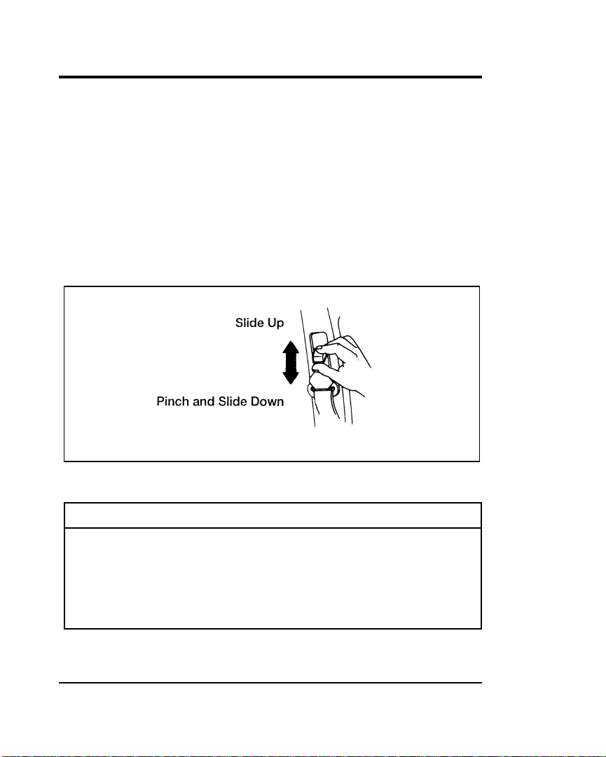
To adjust the belt down, pinch the release button. To adjust the
belt up, pinch the release button and slide the adjuster up.
Make sure the adjuster is firmly in one of the five positions. The
belt should be adjusted up or down until the belt rests on your
shoulder near your neck.
The shoulder belt height adjuster
R WARNING
Position the shoulder belt height adjuster so that the belt
rests across the middle of your shoulder. Be sure the
shoulder belt is properly positioned on your shoulder
each time you use the belt. If the shoulder belt is off
your shoulder, on your upper arm or neck, there is a
greater risk of severe injury in a collision.
17
Page 20

Lap Belt Without a Retractor (for the three-passenger
bench seat)
The center seat of the three-passenger bench seat has a lap belt
without a retractor. To make the belt longer, tip the tongue at a
right angle to the belt and pull the belt over your lap until the
tongue reaches the buckle.
To fasten the belt, pull the belt across your hips and insert the
tongue into the correct buckle on your seat until you hear a
snap and feel it lock. Make sure the buckle is securely fastened.
Adjust the belt so that it fits snugly and as low as possible
around the hips:
■ If you need to lengthen the belt, unfasten it and repeat the
procedure above.
■ If you need to shorten the belt, pull on the loose end of the
webbing.
To store the belt:
Fasten the center tongue and buckle when not in use. This will
prevent the belt from falling between the seat and the seatback.
Auxiliary Safety Restraint System for the Second Row
Bench Seat (7 passenger vehicle)
There is a unique safety restraint system for the outside seating
position of the second row bench seat. It is very important that
you read and understand this section before anyone rides in the
outside seating position (near the sliding door) of the
two-passenger bench seat.
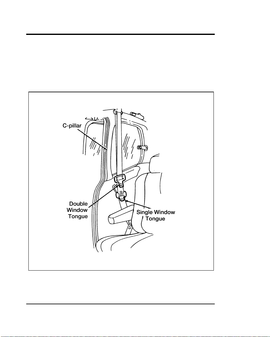
The two-passenger bench seat in the second row has a safety
restraint system made up of two buckles and two tongues.
There is an anchor location at the bottom of the C-pillar and
another anchor location at the top of the C-pillar that attach
each end of the seat belt webbing to the bodyside.
18
Page 21
Safety Restraints
One of the seat belt tongues has two “windows” (or holes) and
the other has only one “window.” The seat belt tongue with one
window attaches to the buckle mounted to the side of the seat.
The seat belt tongue with two windows should be pulled across
the passenger’s chest and fastened to the buckle mounted in the
standard location in the middle of the seat.
The auxiliary safety retraint system for the second row bench seat
19
Page 22
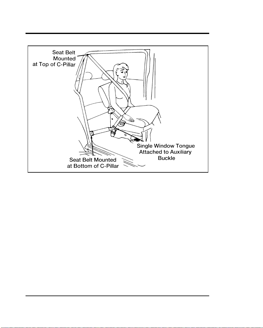
The auxiliary safety restraint system fastened
A twisted belt may prevent the retractor from working
properly. If the unique safety belt system is twisted, disengage
the single window tongue from the buckle on the side of the
seat, remove the twist and re-install the tongue into the buckle
until you hear a snap and feel the latch engage.
NOTE: If the three-passenger bench seat is moved up to the
second-row position, the outside passenger (near the
sliding door) only needs to use the double window
tongue and the standard buckle. Because the third-row
seat is wider and is closer to the sliding door, the
single window tongue and the auxiliary buckle are
not necessary.
20
Page 23
Safety Restraints
Unfastening the auxiliary safety restraint system
Both tongues must be attached to their appropriate buckles
whenever someone is riding in that seating position.
When the two-passenger bench seat is removed from the
vehicle, you must detach the single window tongue from the
auxiliary buckle.
Third-row passengers must be very careful when exiting if the
auxiliary restraint system is being used by a second-row
passenger. It is important to step over the seat belt guide and
belt webbing to avoid tripping.
21
Page 24
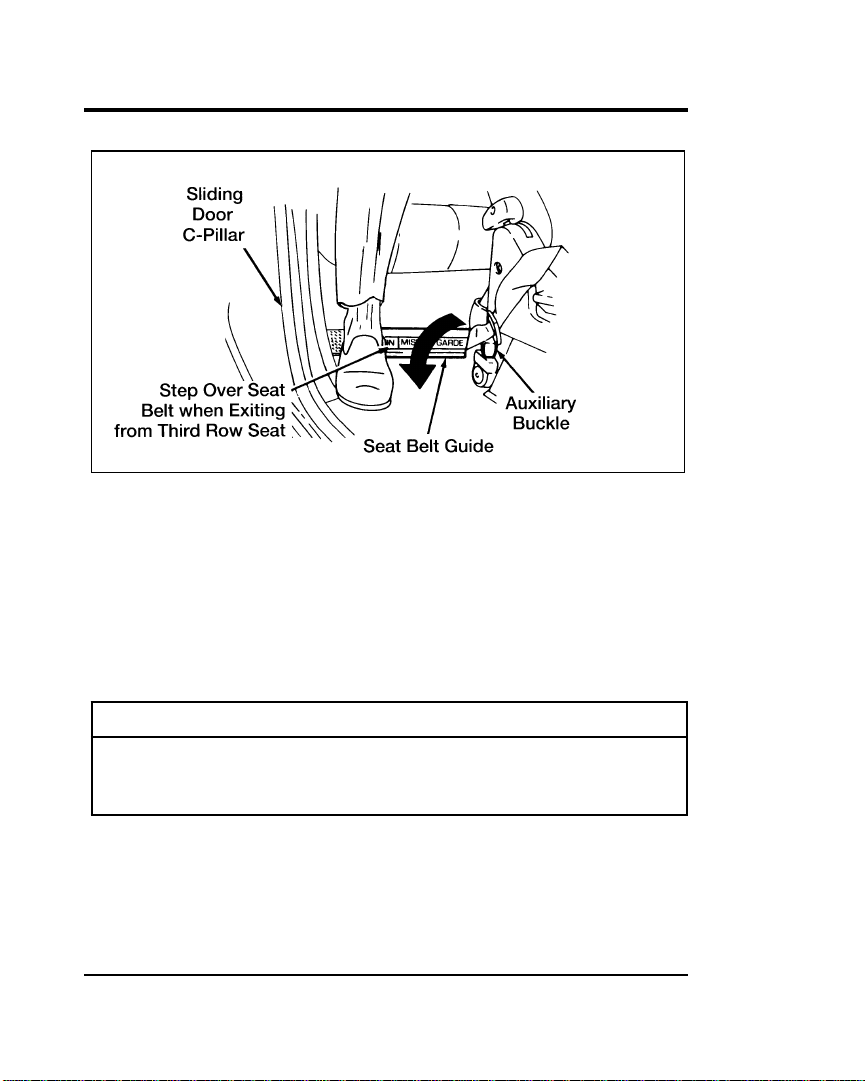
Exiting a vehicle with the auxiliary safety restraint system
Labels are provided on the back of the second-row bench seat
to remind passengers to use care when exiting.
Safety Belt Extension Assembly
A safety belt may be too short even when it is fully extended.
You can add about eight inches (20 cm) to the belt length with
a safety belt extension assembly. Safety belt extensions are
available at no cost (part number 611C22) from your dealer.
R WARNING
Failure to follow these instructions will affect the
performance of the safety belts and increase the risk of
personal injury.
22
Page 25

Safety Restraints
Check the safety belt systems periodically to make sure that
they work properly and are not damaged.
All safety belt assemblies, including retractors, buckles, front
seat belt buckle support assemblies (slide bar) (if so equipped),
child safety seat tether bracket assemblies (if so equipped), and
attaching hardware, should be inspected after any collision. Ford
recommends that all safety belt assemblies used in vehicles
involved in a collision be replaced. However, if the collision was
minor and a qualified technician finds that the belts do not
show damage and continue to operate properly, they do not
need to be replaced. Safety belt assemblies not in use during a
collision should also be inspected and replaced if either damage
or improper operation is noted.
Cleaning the Safety Belts
Clean the safety belts with any mild soap solution that is
recommended for cleaning upholstery or carpets. Do not bleach
or dye the belt because this may weaken it.
(SRS)
The driver and right front passenger air bags are Supplemental
Restraint Systems (SRS), provided at these seating positions in
addition to the lap/shoulder belt, and are designed to
supplement the protection provided to properly belted
occupants in moderate to severe frontal collisions. The
supplemental air bag system does not provide restraint to the
lower body.
23
Page 26
The Importance of Wearing Safety Belts
R WARNING
Safety belts must be worn by all vehicle occupants to be
properly restrained and help reduce the risk of injury in
a collision.
R WARNING
All occupants of the vehicle, including the driver, should
always wear their safety belts, even when an air bag
Supplemental Restraint System is provided.
There are four very important reasons to use safety belts even
with a supplemental air bag system. Use your safety belts to:
■ help keep you in the proper position when the supplemental
air bag inflates
■ reduce the risk of harm in rollover, side or rear impact
accidents. The air bag supplemental restraint system is not
designed to inflate in such situations
■ reduce the risk of harm in frontal collisions that are not
severe enough to activate the supplemental air bag
■ reduce the risk of being thrown from your vehicle
The Importance of Being Properly Seated
In a collision, the air bag must inflate extremely fast to help
provide additional protection for you. In order to do this, the
air bag must inflate with considerable force. If you are not
seated in a normal riding position with your back against the
seatback, the air bag may not protect you properly and could
possibly hurt you as it inflates.
24
Page 27
Safety Restraints
R WARNING
If a passenger is not properly seated and restrained, an
inflating air bag could cause serious injury.
R WARNING
Rear-facing infant seats should never be placed in the
front seat.
In rear-facing infant seats, the infant’s head is closer to the air
bag. The force of the rapidly inflating air bag could push the
top of the rear-facing seat against the vehicle seatback or center
armrests (if so equipped), or center console (if so equipped).
REAR-FACING INFANT CARRIERS MUST ALWAYS BE
SECURED IN THE REAR SEAT, and other child safety seats
and infant seats should be secured in the rear seat whenever
possible.
Your vehicle is equipped with a right front passenger air bag.
Air bags deploy with great force, faster than the blink of an eye.
Front passengers, especially children and small adults, must
never sit on the front edge of the seat, stand near the glove
compartment of the instrument panel, or lean over near the air
bag cover when the vehicle is moving. All occupants should sit
with their backs against the seatback, move the seat to the most
rearward position if possible and use the safety belts. Children
weighing less than 40 lbs. (18 kg) always should use child or
infant seats.
R WARNING
When using forward-facing child seats move the
passenger seat as far back from the instrument panel as
possible. NEVER SECURE REAR-FACING INFANT
SEATS IN THE FRONT SEAT.
25
Page 28

The force of the rapidly inflating passenger air bag could push
the top of the rear-facing seat against the vehicle seatback,
armrests or console. Rear-facing infant seats must always be
secured in the rear seat.
R WARNING
Do not place objects or mount equipment on or near the
air bag cover on the steering wheel or in front seat areas
that may come in contact with a deploying air bag.
Failure to follow this instruction may increase the risk of
personal injury in the event of a collision.
For further information about the proper mounting of
equipment in the front seat of this vehicle, please refer to Ford’s
brochure entitled Some Important Information About Air Bag
Supplemental Restraint System which can be obtained by calling
Helm Inc. at 1-800-782-4356. Ask for brochure FPS-8602.
For additional important safety information on the proper use of
seat belts, child seats, and infant seats, please read the other
sections of this chapter of the Owner Guide, especially sections
entitled Safety Belts for Children and Safety Seats for Children.
How the Air Bag Supplemental Restraint System
Operates
The Air Bag Supplemental Restraint System consists of the
driver and passenger air bags, impact sensors, a system
diagnostic module, a readiness light and tone, and the electrical
wiring which connects the components.
The driver air bag is in the center of the steering wheel. The
front passenger seat air bag is located in the center of the
instrument panel ledge above the glove compartment. Both air
bags are designed to stay out of sight until they are activated.
26
Page 29
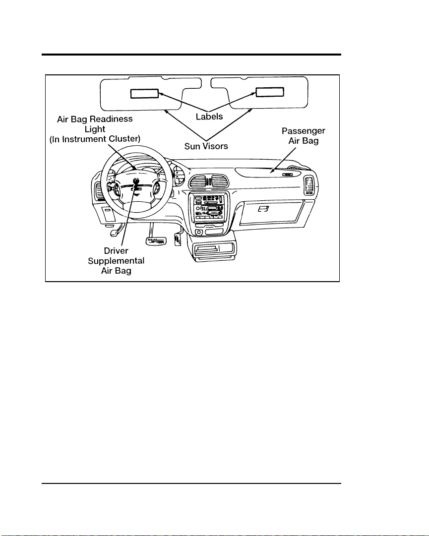
Safety Restraints
The location of air bags and warning labels
If a collision occurs, the sensors sense the severity of the impact
and activate the air bags if necessary. The air bag system is
designed to deploy in frontal and front-angled collisions more
severe than hitting a parked vehicle (of similar size and weight)
head-on at about 28 mph (45 km/h). Because the system senses
the crash severity rather than vehicle speed, some frontal
collisions at speeds above 28 mph (45 km/h) will not inflate the
air bag.
When the sensors activate the system, the air bags inflate
rapidly, filling with non-toxic nitrogen gas in a fraction of a
second. Immediately after inflation, the air bags deflate by
releasing the nitrogen gas through vent holes. The whole
process takes place in a matter of seconds.
27
Page 30
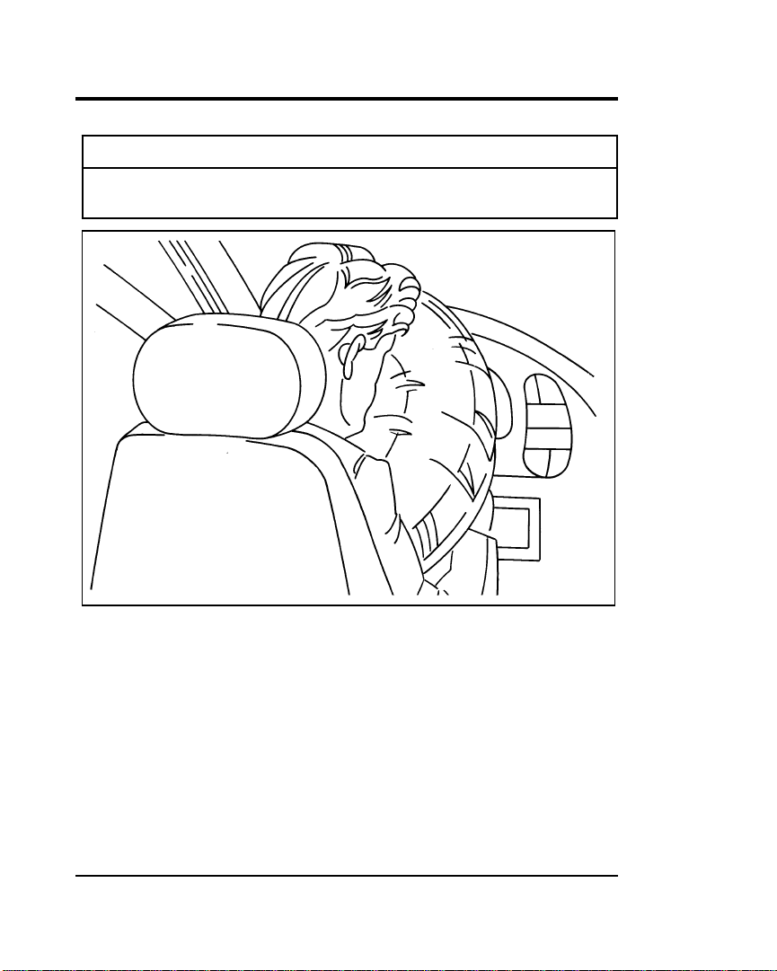
R WARNING
Air bag system components get hot after inflation. Do
not touch them after inflation.
Inflated driver side supplemental air bag
28
Page 31

Safety Restraints
Inflated passenger side supplemental air bag
R WARNING
If the air bag is inflated, THE AIR BAG WILL NOT
FUNCTION AGAIN AND MUST BE REPLACED
IMMEDIATELY. If the air bag is not replaced, the
unrepaired area will increase the risk of injury in a
collision.
To ensure that the air bag system will operate as intended in a
crash, the system is equipped with a diagnostic module, which
controls a readiness lamp and a warning tone. The diagnostic
module monitors its own circuits, the air bag electrical system,
the air bag readiness light, the air bag power, and the air bag
inflators.
29
Page 32

The air bag system uses a readiness light on the instrument
cluster and a tone to indicate the condition of the system. When
you turn the ignition key to the ON position, this light will
illuminate for approximately six (6) seconds and then turn off.
This indicates that the system is operating normally. NOTE:
Maintenance of the air bag system is not required.
A problem with the system is indicated by one or more of the
following:
■ the readiness light will either flash or stay lit,
■ or it will not light immediately after ignition is turned on,
■ or a group of five beeps will be heard. The tone pattern will
repeat periodically until the problem and light are repaired.
If any of these things happen, have the air bag system serviced
at your Ford or Lincoln-Mercury dealer immediately. Unless
serviced, the air bag supplemental restraint system may not
function properly in the event of a collision.
R WARNING
Do not attempt to service, repair, or modify the Air Bag
Supplemental Restraint System or its fuses. See your
Ford or Lincoln-Mercury dealer.
Disposal of supplemental air bags or supplemental air
bag equipped vehicles
For disposal of air bags or air bag equipped vehicles, see your
local Ford or Lincoln-Mercury dealer. Air bags MUST be
disposed of by qualified personnel.
30
Page 33

Safety Restraints
In the U.S. and Canada, you are required by law to use safety
restraints for children. If small children ride in your vehicle —
this generally includes children who are four years old or
younger and who weigh 40 pounds (18 kg) or less — you must
put them in safety seats that are made specially for children.
Safety belts alone do not provide maximum protection for these
children. Check your local and state laws for specific
requirements.
R WARNING
Never let a passenger hold a child on his or her lap
while the vehicle is moving. The passenger cannot
protect the child from injury in a collision.
R WARNING
To prevent the risk of injury, make sure children sit
where they can be properly restrained.
R WARNING
It is extremely dangerous to ride in a cargo area, inside
or outside of a vehicle. In a collision, people riding in
these areas are more likely to be seriously injured or
killed. Do not allow people to ride in any area of your
vehicle that is not equipped with seats and safety belts.
Be sure everyone in your vehicle is in a seat and using a
safety belt properly.
31
Page 34

R WARNING
Whenever possible, put children in one of the rear seats
in your vehicle. Accident statistics indicate that children
are safer when properly restrained in the rear seats than
in the front seats.
R WARNING
Carefully follow all of the manufacturer’s instructions
included with the safety seat you put in your vehicle. If
you do not install and use the safety seat properly, the
child may be injured in a sudden stop or collision.
R WARNING
Safety belts and seats can become hot in a vehicle that
has been closed up in sunny weather; they could burn a
small child. Check seat covers and buckles before you
place a child anywhere near them.
R WARNING
Do not leave children, unreliable adults, or pets
unattended in your vehicle.
Safety Seats for Children
Use a safety seat that is recommended for the size and weight
of the child. Always follow the safety seat manufacturer’s
instructions when installing and using the safety seat.
Ford recommends the use of a child safety seat having a top
tether strap. Install the child safety seat in a seating position
which is capable of providing a tether anchorage. For more
information on top tether straps see Attaching Safety Seats With
Tether Straps in this chapter.
32
Page 35

Safety Restraints
When installing a child safety seat, be sure to use the correct
safety belt buckle for that seating position, and make sure the
tongue is securely fastened in the buckle. For a shoulder/lap
belt combination with a sliding tongue, make sure the retractor
is in the automatic locking mode.
All child restraint systems are designed to be secured in vehicle
seats by lap belts or by the lap portion of a lap-shoulder belt.
R WARNING
REAR-FACING INFANT SEATS SHOULD NEVER BE
USED IN THE FRONT SEAT. REAR-FACING INFANT
SEATS MUST ALWAYS BE PLACED IN THE REAR
SEAT. Failure to follow these instructions could result in
serious injury.
R WARNING
If you do not properly secure the safety seat, the child
occupying the seat may be injured during a collision or
sudden stop. An unsecured safety seat could also injure
other passengers.
R WARNING
Carefully follow all of the manufacturer’s instructions
included with the safety seat you put in your vehicle. If
you do not install and use the safety seat properly, the
child may be injured in a sudden stop or collision.
33
Page 36

The passenger side quick-release second row bucket seat is
adjustable along a track and may be adjusted very close to the
front passenger seat to allow easier entry and exit to third row
seats.
R WARNING
The quick-release seat must be adjusted to the rearmost
position when using an untethered forward-facing child
safety seat.
R WARNING
The third row seat must be adjusted to the rearmost
position when using an untethered forward facing child
safety seat.
R WARNING
Always keep the buckle release button pointing upward
and away from the child seat, with the tongue between
the child seat and the release button as shown in the
following illustration.
34
Page 37

Safety Restraints
Safety belt buckle placement for child seats
Retractor to Secure a Child Safety Seat
Your vehicle is equipped with a dual locking mode retractor on
the shoulder belt portion of the combination lap/shoulder safety
belt for the front passenger seat and rear outer seats. The
automatic locking mode must be used when installing a child
seat or infant carrier in the front passenger seat or rear outer
seats.
R WARNING
Never install a rear-facing child seat or infant carrier in
the right front passenger seat.
35
Page 38

To install a child safety seat or infant carrier, follow these steps:
you are using the moveable third row seat in the third row
position, the passenger side second row bucket seat, or the
front passenger seat, slide the seat to the rearmost position.
instructions. Route the safety belt through the child seat or
infant carrier and insert the safety belt tongue into the
buckle until you hear and feel the latch engage. Be sure to
follow the child safety seat manufacturer’s instructions for
belt routing.
Routing the safety belt tongue through the child seat
retractor and a click is heard.
36
Page 39

Safety Restraints
the belt retracts. This indicates that the retractor is in the
automatic locking mode.
while you push down on the child seat.
Removing slack from the safety belt
37
Page 40

use force to tilt the seat from side to side, and tug it forward
to make sure that the seat is securely held in place.
Testing the security of the child seat
Try to pull more belt out of the retractor. If you cannot, the
belt is in the automatic locking mode.
properly secured prior to each use. If the safety belt is not
locked, repeat steps 3 through 6.
NOTE: When the lap/shoulder belt is unbuckled and allowed
to retract completely, the retractor will switch to the
vehicle sensitive (emergency) locking mode.
38
Page 41

Safety Restraints
The automatic locking mode is activated whenever all of the
belt webbing is pulled out of the retractor.
While in this mode, the belt will retract or tighten but cannot be
pulled back out to obtain more length. To disengage the
automatic locking mode, unbuckle the belt and allow the
webbing to retract fully.
Attaching Safety Seats With Tether Straps
Some manufacturers make safety seats that include a tether
strap that goes over the back of the vehicle seat and attaches to
an anchoring point. Other manufacturers offer the tether strap
as an accessory. Contact the manufacturer of your child safety
seat for information about ordering a tether strap.
All vehicles built for sale in Canada include tether anchor
hardware for use with Canadian child safety seats. The tether
anchor hardware is located in the tire changing tool kit.
Additional tether anchor hardware can be obtained at no charge
from any Ford or Lincoln-Mercury dealer.
Vehicles built for sale in the USA do not include tether anchor
hardware, but it can be obtained at no charge from any Ford or
Lincoln-Mercury dealer (Part number F3XY-12613D20-A).
The chart below specifies, for each seat type and position, where
the tether strap must be attached to the vehicle and the section
containing the appropriate instructions for tethering.
39
Page 42

40
Page 43

Safety Restraints
Tethering to floor anchor
Ford recommends placing tethered safety seats in a rear seating
position with the tether strap attached to the tether anchoring
point as shown in the following illustration.
Tether anchor point locations
To gain access to the anchoring bolt, cut through the plastic
along the U-shaped tether location outlines on the carpet of the
luggage area. Remove the bolt that is currently in the anchor
location. The tether anchor hardware has been preassembled. To
attach it, orient the tab in the bracket toward the front of the
vehicle and securely tighten the bolt. Follow the child safety
seat directions for attaching the tether strap to the anchor
bracket.
41
Page 44

R WARNING
Only use the tether attachment hole locations shown in
the illustrations. The tether anchor may not perform
properly if the wrong mounting location is used.
R WARNING
Failure to follow these precautions could increase the
chance of injury in an accident.
R WARNING
If the anchor bolt(s) is ever removed, the hole(s) in the
floor must be sealed to prevent the possibility of exhaust
fumes entering the passenger compartment.
Tethering to lap/shoulder belt tongue
To attach a tether strap to a lap/shoulder belt:
headrest supports.
the tongue of the lap/shoulder belt directly behind the child
seat position.
foot behind the seatback.
and a click is heard. At this time the belt is in automatic
locking mode (child restraint mode).
belt. A clicking sound should be heard as the belt retracts,
indicating that the retractor is in the automatic locking mode.
Tighten the tether strap to remove any slack.
42
Page 45

Safety Restraints
the child restraint from side to side and tug it forward to
make sure it is securely held in place.
trying to pull more belt out of the retractor. If you cannot
pull any more belt webbing out of the retractor, the belt is in
automatic locking mode.
prior to each use. If the belt is not locked, repeat steps 4
through 7.
43
Page 46

Safety Belts for Children
Children who are too large for child safety seats should always
wear safety belts. (See instructions with your child seat, or
contact its manufacturer, to determine maximum size of a child
that will fit safely in the safety seat.)
R WARNING
If safety belts are not properly worn and adjusted as
described, the risk of serious injury to the child in a
collision will be much greater.
R WARNING
If the shoulder belt portion of one of the lap/shoulder
belts can be positioned so that it does not cross or rest in
front of the child’s face or neck, the child should wear
the lap/shoulder belt. Moving the child closer to the
center of the vehicle may help provide a good shoulder
belt fit.
To improve the fit of lap and shoulder belts on children who
have outgrown child safety seats, Ford recommends use of a
belt-positioning booster seat that is labelled as conforming to all
Federal motor vehicle safety standards. Belt-positioning booster
seats raise the child and provide a shorter, firmer seating
cushion that encourages safer seating posture and better fit of
lap and shoulder belts on the child. A belt-positioning booster
should be used if the shoulder belt rests in front of the child’s
face or neck, or if the lap belt does not fit snugly on both
thighs, or if the thighs are too short to let the child sit all the
way back on the seat cushion when the lower legs hang over
the edge of the seat cushion. You may wish to discuss the
specific needs of your child with your pediatrician.
44
Page 47

Safety Restraints
R WARNING
Do not use a belt-positioning booster with a lap-only
belt.
R WARNING
The lap belt portion of combination lap/shoulder belts
should always be worn snugly and below the hips,
touching the child’s thighs.
R WARNING
Children should always ride with the seatback in the
fully upright position. When the seatback is not fully
upright, there is a greater risk that the child will slide
under the safety belt and be seriously injured in a
collision.
Built-In Child Seats (If equipped)
The optional second row bench seat includes two built-in child
seats. These child restraints are to be used only by children
who:
■ are at least one year old
AND
■ weigh between 9 and 27 kilograms (20 and 60 pounds)
AND
■ whose shoulders are below the shoulder harness slots
45
Page 48

Children not meeting these requirements should be restrained in
an approved aftermarket child safety seat. Follow the specific
manufacturer’s instructions for weight and height restrictions.
Children must be properly buckled before riding in the vehicle.
It is the law in every state and province. These child seats
conform to all Federal/Canadian motor vehicle safety standards.
R WARNING
The second row seatback must be fully locked before
operating the child restraint system. Check the position
of the seatback release lever.
46
Page 49

Safety Restraints
Second row bench built-in child seats
Built-In Child Seat Retractors
The retractor will switch from the emergency locking mode to
the automatic locking mode when the right shoulder belt is
pulled all the way out. The retractor will switch back to
emergency locking mode when the belts are unbuckled and the
shoulder belts retract completely.
The automatic locking mode must be used to hold small
children in position, particularly sleeping children and those
who may try to squirm out of the belts. The emergency locking
mode is used while buckling the belts.
Always adjust the lap and shoulder harness belts provided with
this child seat snugly around your child.
47
Page 50

R WARNING
The child seats’ metal and plastic parts can become very
hot when left in the sun. These can cause burns to
unprotected skin.
R WARNING
Failure to follow all of the instructions on the use of this
child restraint system can result in your child striking the
vehicle’s interior during a sudden stop or crash.
How to Use the Built-In Child Seat
Read the following procedures and all of the labels on the
built-in child seat before using the seat.
R WARNING
Never use the Built-In Child Seat as a booster cushion
with the adult safety belts. A child using the adult belts
could slide forward and out from under the safety belts.
and lower the cushion completely.
48
Page 51

Safety Restraints
49
Page 52

detach the chest clip.
50
Page 53

Safety Restraints
51
Page 54

belt buckle between the child’s legs.
52
Page 55

Safety Restraints
shoulder. Insert the left shoulder harness tongue into the left
side of the belt buckle. Confirm that the left shoulder
harness tongue indicator is green.
shoulder. Insert the right shoulder harness tongue into the
right side of the belt buckle. Confirm that the right shoulder
harness tongue indicator is green.
shoulders. Adjust the clip to comfortably hold the shoulder
belts in place on the child’s chest. Confirm that the chest clip
indicator is green.
NOTE: The chest clip can be easily pulled apart and is
designed to separate during a collision.
53
Page 56

the locking mode. At this time, the shoulder belts are in an
automatic locking mode. Allow the safety belts to tighten
snugly against the child’s shoulders. The belt will
automatically lock and cannot be pulled out.
unbuckle the child from the built-in child seat. Allow the
shoulder belts to retract fully. Repeat the procedure from
step 3 through step 7.
54
Page 57

Safety Restraints
Removing the child from the built-in child seat
the top and bottom edges of the center of the chest clip. Pull
the two halves apart.
child from the built-in child seat.
resting inside the built-in child seat recess. It is unnecessary
to reconnect the shoulder harness and belt buckle prior to
storing the built-in child seat.
55
Page 58

upward until it fits flush with the second row seatback pad.
position by grasping the safety seat cushion and attempting
to lower it without pulling the cushion release strap.
repeat steps 4 through 6.
56
Page 59

Starting Your Villager
Understanding the Positions of the Ignition
Your vehicle’s ignition has four positions. They are:
The ignition positions
ON allows you to test your vehicle’s warning lights to make
sure they work before you start the engine. The key returns to
the ON position once the engine is started and remains in this
position while the engine runs.
START cranks the engine. Release the key once the engine starts
so that you don’t damage the starter. The key should return to
the ON position when you release it.
OFF/LOCK allows you to shut off the engine and all accessories
and locks the gearshift lever. Removing the key then locks the
steering wheel.
57
Page 60

ACCESSORY allows you to operate some of your vehicle’s
electrical accessories while the engine is not running. For
example, you can use ACCESSORY to turn on the radio,
windshield wipers, or operate the cigarette lighter without
starting the engine.
Ignition Key Chime
The chime will sound if you open the driver’s door while the
key is in the ignition. Never leave your vehicle unattended with
the key in the ignition.
Removing the Key From the Ignition
OFF/LOCK is the only position that allows you to remove the
key from the ignition. The LOCK feature helps to protect your
vehicle from theft, because it also locks the steering wheel and
the gearshift lever when the key is removed.
If your key is stuck in the LOCK position, and you are unable
to turn it, move your steering wheel left or right until the key
turns freely.
To remove your key from the ignition:
RWARNING
When you leave your vehicle, place the gearshift lever in
P (Park). Set the parking brake fully, and shut off the
engine. Never park your vehicle in N (Neutral). If you do
not take these precautions, your vehicle may move
suddenly and injure someone.
58
Page 61

Starting Your Villager
RWARNING
Do not leave children, unreliable adults, or pets alone in
your vehicle. They could accidentally injure themselves
or others through inadvertent operation of the vehicle.
Further, on hot, sunny days, temperatures in a closed
vehicle could quickly become high enough to cause
severe and possibly fatal injuries to people as well as
animals.
When starting a fuel-injected engine, the most important thing
to remember is to avoid pressing down on the accelerator
before or during starting. Only use the accelerator when you
have problems getting your vehicle started. See Starting Your
Engine in this chapter for details about when to use the
accelerator while you start your vehicle.
Preparing to Start Your Vehicle
RWARNING
Do not start your vehicle in a closed garage or other
enclosed area. Never sit in a stopped vehicle for more
than a short period of time with the engine running.
Exhaust fumes are toxic. See Guarding Against Exhaust
Fumes in this chapter for more instructions.
Before you start your vehicle, always:
belts. See Safety belts in the Index for more details.
off when starting.
59
Page 62

brake is set before you turn the key.
sure they work. Refer to the Warning Lights and Gauges
chapter.
Starting Your Engine
To start your engine:
beginning of this section.
to ON.
engine. DO NOT use the accelerator while the vehicle is
parked.
engine starts. Allow the key to return to the ON position
after the engine has started.
wheel slightly because it may be binding.
For a cold engine:
■ At temperatures 10˚F (-12˚C) and below: If the engine does
not start in fifteen (15) seconds on the first try, turn the key
to OFF, wait approximately ten (10) seconds so you do not
flood the engine, then try again.
■ At temperatures above 10˚F (-12˚C): If the engine does not
start in five (5) seconds on the first try, turn the key to OFF,
wait approximately ten (10) seconds so you do not flood the
engine, then try again.
60
Page 63

Starting Your Villager
For a warm engine:
■ Do not hold the key in the START position for more than
five (5) seconds at a time. If the engine does not start within
five (5) seconds on the first try, turn the key to the OFF
position. Wait a few seconds after the starter stops, then try
again.
Whenever you start your vehicle, release the key as soon as the
engine starts. Excessive cranking could damage the starter or
flood the engine.
After you start the engine, let it idle for a few seconds. Keep
your foot on the brake pedal and release the parking brake.
Put the gearshift lever in gear, slowly release the brake pedal
and drive away in the normal manner.
NOTE: Your vehicle has an interlock that prevents you from
shifting out of Park (P) unless your foot is on the
brake pedal.
If the engine does not start after two attempts:
Then drive away in the normal manner.
If the engine still does not start, the fuel pump shut-off switch
may have been triggered. For directions on how to reset the
switch see Fuel Pump Shut-Off Switch later in this chapter.
61
Page 64

A computer system controls the engine’s idle speed. When you
start your vehicle, the engine’s idle speed normally runs high.
These faster engine speeds will make your vehicle move slightly
faster than its normal idle speed. It should, however, slow down
after a short time. If it does not, have the idle speed checked.
If the engine idle speed does not slow down automatically, do
not allow your vehicle to idle for more than 10 minutes. Have
the vehicle checked.
RWARNING
Extended idling at high engine speeds can produce very
high temperatures in the engine and exhaust system,
creating the risk of fire or other damage.
RWARNING
Do not park, idle, or drive your vehicle in dry grass or
other dry ground cover. The emission system heats up
the engine compartment and exhaust system, which can
start a fire.
If you consistently start your vehicle in subzero temperatures,
use an engine block heater (if your vehicle has this option).
Engine Block Heater (If equipped)
Engine block heaters are strongly recommended if you live in a
region where temperatures reach s10˚F (s23˚C) or below. An
engine block heater warms the engine coolant, which improves
starting, warms up the engine faster, and allows the
heater-defrost system to respond more quickly.
RWARNING
To prevent electrical shock, do not use your heater with
ungrounded electrical systems or two-pronged (cheater)
adapters.
62
Page 65

Starting Your Villager
For best results, plug the heater in at least three hours before
you start your vehicle. Using the heater for longer than three
hours will not damage the engine, so you can leave it plugged
in all night to start your vehicle the following morning.
Fuel Pump Shut-Off Switch
If the engine cranks but does not start or does not start after a
collision, the fuel pump shut-off switch may have been
triggered. The shut-off switch is a device intended to stop the
fuel pump when your vehicle has been involved in a substantial
jolt.
Once the shut-off switch is triggered, you must reset the switch
by hand before you can start your vehicle.
The fuel pump shut-off switch reset button is located below the
hood release handle.
Fuel pump shut-off switch reset button location
63
Page 66

RWARNING
If you see or smell fuel, do not reset the switch or try to
start your vehicle. Have all the passengers get out of the
vehicle and call the local fire department or a towing
service.
If your engine cranks, but does not start after a collision:
reset button down. If the red button is already set, you may
have a different mechanical or electrical problem.
then turn it to the OFF position.
smell fuel, do not start your vehicle again. If there is no fuel,
you can try to start your vehicle again.
Guarding Against Exhaust Fumes
Carbon monoxide, although colorless and odorless, is present in
exhaust fumes. Take precautions to avoid its dangerous effects.
RWARNING
Never let your vehicle idle in an enclosed area, and do
not sit in a parked vehicle, (with the engine running) for
more than a short period of time. Exhaust fumes,
particularly carbon monoxide, might build up. These
fumes are harmful and could kill you.
64
Page 67

Starting Your Villager
RWARNING
If you ever smell exhaust fumes of any kind inside your
vehicle, have your dealer inspect and fix your vehicle
immediately. Do not drive if you smell exhaust fumes.
These fumes are harmful and could kill you.
Have the exhaust and body ventilation systems checked by a
qualified technician whenever:
■ your vehicle is raised for service
■ the sound of the exhaust system changes
■ your vehicle has been damaged in an accident
Improve your ventilation by keeping all air intake vents clear of
snow, leaves, and other objects.
If the engine is idling while you are stopped in an open area
for long periods of time, open the windows at least one inch
(2.5 cm). Also, adjust the heating or air conditioning to bring in
outside air.
Read the section Climate Control Systems for instructions on
bringing fresh outside air into your vehicle. Refer to the Index.
65
Page 68

Warning Lights and Gauges
The instrument panel (dashboard) on your vehicle is divided
into several different sections. The illustrations on the following
pages show the major parts of the instrument panel described in
this chapter. Some items shown may not be on all vehicles.
To clean the lenses on your instrument panel, use Ford Glass
Cleaner and a soft cloth. Never use paper towels or abrasive
cleaners; they can scratch the lenses.
In your vehicle, the warning lights and gauges are grouped
together on the instrument panel. We call this grouping a
cluster. Your vehicle may have a mechanical cluster or an
electronic cluster.
If you are not sure which cluster your vehicle has, check the
diagrams on the following pages.
67
Page 69

68
Mechanical cluster
Page 70

Warning Lights and Gauges
The following warning lights and gauges are on the mechanical
cluster. All of the warning lights and gauges alert you to
possible problems with your vehicle. Some of the lights listed
are optional. The following section explains what each of these
indicators means.
Brake System Warning Light
The warning light for the brakes can show two things — that
the parking brake is not fully released, or that the brake fluid
level is low in the master cylinder reservoir. If the fluid level is
low, the brake system should be checked by your dealer or a
qualified service technician.
Brake system and parking brake light
The BRAKE light normally comes on when you turn the
ignition key to the ON position to verify that the indicator bulb
is working. If the light stays on or comes on when the engine is
running and after you have released the parking brake fully,
have the hydraulic brake system serviced.
RWARNING
The BRAKE light indicates that the brakes may not be
working properly. Have the brakes checked immediately.
69
Page 71

Anti-Lock Brake System Warning Light (If Equipped)
To check the anti-lock brake warning light, turn the ignition key
to the ON position. The ABS warning light should glow
momentarily.
NOTE: If it does not glow at all or stays on for a long time,
have your vehicle’s electrical system checked
immediately.
Anti-lock brake system warning light
RWARNING
If the anti-lock brake system warning light remains on or
comes on while driving, have the braking system checked
by a qualified service technician as soon as possible.
NOTE: If a fault occurs in the anti-lock system, and the brake
warning light is not lit, the anti-lock system is
disabled but normal brake function remains
operational.
Safety Belt Warning Light and Chime
This warning light and chime remind you to fasten your safety
belt.
■ If the safety belt is not buckled when the ignition is turned
to the ON position, the chime will turn on for four (4) to
eight (8) seconds and the light will remain on continuously,
or until the safety belt is fastened.
70
Page 72

Warning Lights and Gauges
■ If the safety belt is buckled while the light is on and the
chime is sounding, both the light and chime will turn off.
■ If the safety belt is buckled before the ignition is turned to
the ON position, the chime does not sound, and the warning
light will not illuminate.
Safety belt warning light
Air Bag Readiness Light
The supplemental air bag system uses a readiness light to
indicate the condition of the system. If the system is functioning
properly, the light will stay on for about six (6) seconds when
the ignition switch is turned to the ON position.
If there is a problem with the system, the readiness light may
fail to illuminate, continue to flash, or remain on. If any of these
conditions occur, have the system serviced as soon as possible.
Unless the system is serviced, the supplemental air bag system
may not function properly in the event of a collision.
A problem with the system is indicated by one or more of the
following: the readiness light will either flash or stay lit, or it
will not light, or a group of five beeps will be heard.
RWARNING
If any of these things happen, even intermittently, have
the air bag system serviced at your Ford or
Lincoln-Mercury dealer immediately.
71
Page 73

Supplemental air bag readiness light
Check Engine Warning Light
This light comes on when the electronic engine control system is
not working properly. This is the computer that controls the
operating conditions of the engine.
Check engine warning light
This light comes on briefly when you turn the ignition key to
ON, but should turn off when the engine starts. If the light does
not come on when you turn the ignition to ON or if it comes
on and stays on when you are driving, have your vehicle
serviced as soon as possible. This indicates a possible problem
with one of the engine’s emission control systems. You do not
need to have your vehicle towed.
If the light turns on and off briefly while you are driving, it
means that the condition is no longer present.
72
Page 74

Warning Lights and Gauges
Charging System Light
This light, shown as a battery symbol on your cluster, indicates
that your battery is not being charged and that you need to
have the electrical system checked.
Charging system light
This light comes on every time you turn your ignition key to
the ON or START position. The light should go off when the
engine starts and the alternator begins to charge.
If the light stays on or comes on when the engine is running,
have the electrical system checked as soon as possible.
Engine Oil Pressure Warning Light
The oil pressure light is represented by an oil can symbol. It
indicates the engine’s oil pressure, not oil level. However, if
your engine’s oil level is low, it could affect the oil pressure.
The oil can symbol will flash if the oil pressure drops below the
normal operating level. When you turn the key to the ON
position, the light will illuminate.
Oil pressure light
73
Page 75

The light should turn off after a few seconds. If the light stays
on or illuminates when the engine is running — you have lost
oil pressure and continued operation will cause severe engine
damage.
If you lose engine oil pressure:
safely possible, severe engine damage could result.
and adding engine oil in this owner guide. (See Engine oil in
the index.) Make sure your vehicle is on level ground.
drive your vehicle again. Do not drive your vehicle if the oil
pressure light is on, even if the oil level is correct. For more
information about adding oil, see Engine oil, checking and
adding in the Index.
Door Ajar Warning Light
If the ignition switch is in the ON position and any door or the
liftgate is not completely closed, the light will illuminate.
Door ajar warning light
74
Page 76

Warning Lights and Gauges
Cruise Indicator Light
The CRUISE indicator light will illuminate when the speed
control system is activated.
Cruise indicator light
Overdrive Off Indicator Light
If you choose to drive in the D (Drive) gear position instead of
in j (Overdrive), you can use the OVERDRIVE OFF/ON
button on the gearshift selector lever. When you drive with the
vehicle in the Overdrive Off position, the O/D OFF indicator
light will illuminate. The light also illuminates briefly when the
key is turned to the ON position.
Overdrive off indicator light
If the light flashes for about 8 seconds when the ignition is
turned to ON, it means the transaxle control unit received an
improper signal the last time the vehicle was operated. It may
be necessary to have your dealer check the transaxle.
75
Page 77

Low Fuel Light
The low fuel light illuminates when the fuel sensor indicates
approximately 1/8 of a tank. It will remain illuminated until the
tank is filled with enough fuel to pass the 1/8 full level.
Low fuel light
Low Washer Fluid Light
The low washer fluid light will remain illuminated when the
washer fluid sensor indicates that the washer fluid level is low.
Low washer fluid light
76
Page 78

Warning Lights and Gauges
High Beam Light
This light comes on when the headlamps are turned to high
beam or when you flash the lights.
High beam light
“Headlamps On” Alert Chime
This chime will sound if you open the door while the
headlamps or parking lamps are on.
Fuel Gauge
The fuel gauge displays approximately how much fuel you have
in the fuel tank. The fuel gauge indicator may vary slightly
while the vehicle is in motion. This is the result of fuel
movement within the tank. An accurate reading may be
obtained when the vehicle is on smooth, level ground.
Fuel gauge
77
Page 79

Engine Coolant Temperature Gauge
This gauge is accompanied by a thermometer symbol. It will
show you the temperature of the engine coolant when the
ignition is in the ON position.
As the engine warms up, the pointer will move to the
NORMAL band. When you are driving in heavy traffic or
experiencing stop-and-go conditions in hot weather, the pointer
may move to the very top of the normal band.
Under any circumstances, if the pointer moves past the upper
limit of the NORMAL band, the engine is overheating and
engine damage may occur.
If your engine overheats:
safely possible, severe engine damage could result.
SYSTEM FILL CAP UNTIL THE ENGINE IS COOL.
checking and adding coolant to your engine, see Engine
coolant in the Index. If you do not follow these instructions,
you or others could be injured.
continues to overheat, have the coolant system serviced.
78
Page 80

Warning Lights and Gauges
Engine coolant temperature gauge
Speedometer
The speedometer tells you how many miles (kilometers) per
hour your vehicle is moving.
Odometer
The odometer records the total distance the vehicle has been
driven.
79
Page 81

Trip Odometer
The trip odometer records the distance of individual trips.
Before each trip, set the trip odometer to zero by pushing the
reset button.
Speedometer, odometer and trip odometer
Tachometer
The tachometer tells you how fast the engine is running by
indicating approximate engine revolutions per minute.
Driving with the pointer in the red zone may cause engine damage.
Engine coolant temperature gauge
80
81
Page 82

Electronic cluster
Warning Lights and Gauges
Page 83

The electronic cluster has all of the same warning lights as the
mechanical cluster, however, some of the gauges will be
electronic instead of analog. In addition, the electronic cluster
has a fuel computer for measuring fuel economy, distance to
empty and outside air temperature.
Engine Coolant Temperature Gauge
This gauge shows you the temperature of the engine coolant
and is identified by a thermometer symbol. The letter H means
that the coolant is hot, C means that it is cold, and NORMAL
means that the coolant is within the normal operating range.
The indicator bar on the graph will move into the normal
operating range as the engine warms up. When you are in
heavy traffic or stop-and-go driving in hot weather, the gauge
may read at the very top of the NORMAL range. This is
acceptable.
However, if the indicator bar on the graph moves into the
H (hot) position, the engine is overheating and may cause
engine damage. If this happens, you should stop your vehicle as
soon as safely possible. Turn off the engine and let it cool.
Check the coolant level to be sure that it is at the proper level.
If your vehicle needs more coolant, see Engine coolant, checking
and adding in the Index and read the section regarding adding
coolant.
82
Page 84

Warning Lights and Gauges
Engine coolant temperature gauge
Fuel Gauge
The fuel gauge displays approximately how much fuel you have
in the fuel tank. The number of bars illuminated in the display
indicates how much fuel is left. An accurate reading may be
obtained when the vehicle is on smooth, level ground.
Fuel gauge
83
Page 85

Fuel and Distance Computer
Fuel and distance computer
The fuel and distance computer has five buttons to operate the
different functions.
SELECT — The SELECT button lets you choose the functions
of the fuel computer. Each time you press the SELECT
button, the computer advances to the next choice on the
menu. After it reaches the last choice on the menu, it returns
to the top of the menu.
RESET — The RESET button is used to reset the Average
Economy function. Press the SELECT button until the
Average Economy function is displayed. Then press the
RESET button.
ENG/MET — The ENG/MET button allows you to change
your gauges from English to metric units or from metric to
English units. The displays remain in the units you choose
until you change them again, even after you turn off the
vehicle and start it again.
TRIP/RST — The TRIP/RST button is used to reset the trip
odometer mileage. Press the OD/TRIP button until the trip
odometer mileage is displayed. Then press the TRIP/RST
button.
84
Page 86

Warning Lights and Gauges
OD/TRIP — The OD/TRIP button lets you switch the
display between the permanent odometer mileage and the
trip odometer mileage.
Fuel computer functions
Fuel and distance computer display
OUTSIDE TEMP
This feature lets you display the temperature of the air outside
of your vehicle.
The fuel and distance computer is designed to prevent
inaccurate temperature display readings. For example, a sudden
temperature change (such as driving out of a cool garage on a
warm day), may show outside temperature display readings
which are lower than expected. The accurate temperature will
be displayed after the vehicle has reached the outside
temperature and is driven at speeds of 30 mph (48 km/h) or
greater.
In the event of a decrease in the outside air temperature, there
will be no delay in an accurate temperature display.
85
Page 87

INST ECONOMY
Your instantaneous fuel economy is the fuel economy you get at
any particular moment. For example, you can see what your
fuel economy is in heavy traffic or on the highway.
Factors such as braking, acceleration, and road terrain affect
your fuel economy.
To display instantaneous fuel economy, press the SELECT
button until the menu displays INST ECONOMY. Your vehicle
must be moving for the computer to calculate a fuel economy
greater than zero.
AVG ECONOMY
The average fuel economy is an overall average of your fuel
economy taken from the last time the reset button was pushed.
The computer takes an average of all the types of driving you
have done since the RESET button was pressed (highway, city,
heavy traffic), and figures out the average fuel economy. You
can calculate your average fuel economy as often as you like.
For example, you can calculate the average fuel economy for
each tank of fuel or for every day.
To display the average fuel economy:
ECONOMY.
tank of fuel or for each trip you take. Each time you want to
recalculate the average fuel economy, you need to press the
RESET button. The average fuel economy must be displayed
to reset the fuel computer.
The best time to reset the AVG ECONOMY is when you fill
the fuel tank or at the beginning of a trip.
86
Page 88

Warning Lights and Gauges
TO EMPTY
The Distance to Empty function tells you approximately how
many miles or kilometers you can drive until you run out of
fuel.
To see the Distance to Empty, press the SELECT button until
the menu displays TO EMPTY. The fuel computer displays
approximate distance to empty until you select another function.
To ensure accuracy, turn the ignition to the OFF position when
you fill the fuel tank.
87
Page 89

89
Instrument panel
Instrument Panel Controls
Page 90

The instrument panel (dashboard) on your vehicle is divided
into several different sections. Illustrations are provided for the
major parts of the instrument panel that are explained in this
chapter. Some items shown may not be on all vehicles.
90
Page 91

Instrument Panel Controls
The controls for the climate control systems, headlamps, clock,
radio, rear window washer and wiper, hazard flasher, power
switch, and speed control are all on the instrument panel.
Climate control system panel
Function Selector Buttons
There are six function selector buttons: OFF, Mix, Defrost, Panel,
Panel/Floor, and Floor. When you press a function selector
button, the indicator light on the button will illuminate. If your
vehicle is equipped with a rear passenger compartment climate
control system, the instrument panel will also include a rear seat
function selector lever.
■ The OFF button shuts off the air supply to all outlets and
stops all fan operations. Use this setting when driving
through an area where outside air is unpleasant or dusty.
91
Page 92

RWARNING
Operating with the function selector button in OFF or in
the recirculated air mode for extended periods of time in
cold weather can result in fog buildup on interior glass
surfaces. This fogging can make it difficult to see the
road for safe driving. Operating the system with outside
air (i.e., with the air intake selector button off) and with
one of the five function selector buttons selected (Defrost,
Mix, Floor, Panel/Floor, or Panel), will help prevent
fogging. Adjust the temperature as necessary for comfort.
■ The Mix (P) button directs approximately equal amounts of
air to the windshield and floor outlets with a small amount
to the side windows.
■ The Defrost (V) button directs air to the windshield with a
small amount going to the floor outlets.
■ The Panel (Q) button directs air to the instrument panel
outlets.
■ The Panel/Floor (S) button directs approximately equal
amounts of air to the instrument panel outlets and the floor
outlets.
■ The Floor (R) button directs most of the system’s air
supply to the floor outlets with a small amount going to the
windshield and side window defrosters.
92
Page 93

Instrument Panel Controls
Air Outlets
Air intake selector button
The typical air intake selection is outside air. However, for
recirculated air, the air intake selector button may be activated.
When the air intake selector button is activated (indicator light
is on), it prevents the intake of outside air. This is the typical
selection when using the air conditioner (if equipped). It
recirculates interior air for faster cooling. The recirculated air
function also helps to prevent the intake of dusty or unpleasant
air.
There are several air outlets on the instrument panel. There are
side outlets near the driver’s window and passenger’s window,
two center outlets, floor outlets, and windshield outlets. The
direction and amount of air flow from the center and side
instrument panel outlets can be adjusted for personal comfort.
NOTE: Selection of the recirculated air mode under cold and
humid conditions may result in window fogging due
to entrapped humidity within the vehicle. To
counteract this circumstance, switch to the Defrost
mode and set fan speed to 3 or 4. Adjust air
temperature to a “warm” instead of “hot” setting.
Heating Only System (Without air conditioning)
You can heat and ventilate the inside of your vehicle, or defrost
the windshield with the function selector buttons, the fan speed
knob and the temperature control knob.
An additional push-on/push-off air intake selector button
provides for the selection of recirculated inside air (button
lighted) or outside air (button not lighted).
93
Page 94

Turning on the heat
Heat will be available when the engine has been running for a
sufficient time as indicated by the engine coolant temperature
gauge.
To heat the inside of your vehicle:
Heating only climate control system panel
area.
your vehicle warms up, you may want to set the fan speed
knob to a lower speed, or adjust the temperature control
knob to a lower setting to maintain a comfortable
temperature.
94
Page 95

Instrument Panel Controls
To defrost the windshield and side windows:
■ Press the Defrost button, turn the temperature control knob
to the WARM (red) area and turn the fan speed knob to the
position of your choice. The recirculated air feature will be
automatically turned off in this setting (outside air will be
provided).
■ To reduce window fogging under extreme conditions, select
defrost and high fan speed while reducing temperature to a
“warm” instead of “hot” setting. Slightly opening the rear
quarter windows may also help dry the interior window
surfaces.
To heat and defrost at the same time:
■ Press the Mix function selector button, turn the temperature
control knob and the fan speed knob to provide the
temperature and fan speed you prefer. The recirculated air
feature will be automatically turned off in this setting
(outside air will be provided).
Controlling the Temperature in Your Vehicle
■ To ventilate your vehicle with outside air, make sure that the
air intake selector button is set for outside air. Open the
instrument panel registers enough to provide the amount of
air desired for your comfort.
■ To vary the temperature inside your vehicle, move the
temperature control knob toward WARM (red) for warmer
temperatures and toward COOL (blue) for cooler
temperatures. The temperature control knob setting
determines the temperature of the air being discharged from
the system in all operating modes (heating or A/C).
■ Do not place objects under the front seats unless your
vehicle is equipped with an underseat storage compartment.
Improperly stored objects will interfere with the flow of air
to the back seats.
95
Page 96

■ Remove any snow, ice, or leaves from the area below the
windshield on the outside of your vehicle. They could block
the air intake.
Heating and Air Conditioning System (If equipped)
Turning on the heat
You can heat the inside of your vehicle and defrost the
windshield using the function selector buttons located in the
control assembly in the instrument panel.
The six function selector buttons are: OFF, Mix (P), Defrost
( V) Panel (Q), Panel/Floor (S), and Floor (R). If your
vehicle is equipped with a rear seat climate control system, the
instrument panel will also include a rear seat climate control
lever. To turn on the rear passenger compartment control
system, select REAR, 1, 2, 3, or 4. With the lever set to REAR,
rear seat passengers will have control of rear fan speed on the
rear seat climate control panel. Positions 1, 2, 3, or 4 will control
rear fan speed from the front control panel. The temperature of
the air from the rear system is controlled by the rear passenger
compartment climate control system.
96
Page 97

Instrument Panel Controls
Heating and air conditioning climate control system panel
The standard heating system and the heating portion of the
heating and air conditioning system are essentially identical.
There is one exception, however; the air conditioning
compressor may automatically engage when the Defrost position
is selected to aid in defogging and defrosting the inside glass.
When Defrost is selected, the A/C compressor will
automatically operate when the outside temperature is above
approximately 40˚F (4˚C), whether or not the A/C button is
illuminated. Manual selection and illumination of the A/C
button in defrost mode does not override the automatic
compressor operation discussed above. Refer to the heating
system operating instructions covered previously for a more
detailed explanation of heating system operation.
Turning on the air conditioner
To cool your vehicle quickly in warm weather:
but Panel/Floor, Floor or Mix can be selected).
97
Page 98

will illuminate.
mode or the recirculated air mode. The recirculated air mode
is recommended for best A/C performance when the vehicle
interior is very warm. As interior air comfort is reached, you
may decide to switch to the outside air mode.
compartment air conditioning unit, it will be on when the
front A/C is on and the rear climate control lever is set to
REAR, 1, 2, 3, or 4. Refer to the previous section for an
explanation of the heating system.
drive for a few minutes with the windows down and the air
conditioner on. This forces most of the hot, stale air out of
the vehicle and allows the air conditioner to cool down the
interior more quickly.
The air conditioner may be used to cool the outside air being
drawn into your vehicle, but using recirculated air is more
economical and cools your vehicle more quickly.
NOTE: The A/C button independently toggles the A/C
system’s compressor signal and indicator light ON and
OFF in the Panel, Panel/Floor, Floor, Defrost and Mix
functions. The A/C button will not operate or light
when the system is set in the OFF position. The A/C
button will operate in defrost but will not override
previously discussed automatic operation.
98
Page 99

Instrument Panel Controls
Cooling your vehicle with outside air
Cooling your vehicle with air conditioned outside air is quieter
but less economical than using recirculated air. It also has less
cooling capacity.
To cool your vehicle using outside air:
position). The air conditioning unit directs outside air
through the instrument panel registers.
will illuminate.
During periods of high humidity, vapor may be emitted from
the air outlets when using the A/C with outside air. Correct
this by switching to recirculated air with the A/C button.
Ventilating your vehicle with outside air
In mild weather, you can ventilate your vehicle with outside air.
If the outside temperature is less than 70˚F (21˚C), you can add
cool air to your vehicle without using air conditioning. You will
get better fuel economy this way.
The procedure for ventilating your vehicle with the standard
heating system or with the air conditioning system is the same.
Refer to the previous section for instructions on how to ventilate
with outside air.
99
Page 100

Improving fuel economy
Whenever you turn on the air conditioning, your vehicle uses
more fuel because the air conditioning compressor is running.
To get better fuel economy while cooling your vehicle, do not
use the air conditioner on mild days. Instead, set the air intake
selector button in the outside air position and turn the
temperature control knob to the COOL position.
Operating tips
When stopped in traffic for long periods of time in hot weather,
place the automatic transaxle gearshift selector lever in P (Park)
or in N (Neutral) to increase the engine idle speed. This aids in
engine cooling and air conditioner efficiency. If the engine
overheats, choose the outside air position and turn off the A/C
to stop the compressor for a short time.
When your vehicle’s engine is operated at full throttle, the air
conditioner compressor will automatically be turned off to allow
maximum engine power. This may occur during passing or
when climbing steep grades. The compressor will return to
normal operation within a few seconds after full throttle is no
longer needed.
NOTE: The compressor will not operate when the outside
temperature is less than about 40˚F (4˚C).
100
 Loading...