

Page 1
VesselView Link,
502, and 702
OPERATION MANUAL
For All Multi-Function Displays Using the VesselView Link
Page 2

8M0109374 616 eng
VesselView 502 and 702
© 2016 Mercury Marine
Page 3

Page 4

TABLE OF CONTENTS
Section 1 - Getting Started
Declaration of Conformity.......................................................... 2
VesselView 502.................................................................... 2
Test Reports......................................................................... 2
Notified Body Involved..........................................................2
VesselView 702.................................................................... 3
Test Reports......................................................................... 3
Notified Body Involved..........................................................3
VesselView Overview................................................................ 3
VesselView Screen Display Locations and Descriptions..... 4
VesselView 502 Front Controls............................................ 6
VesselView 502 Front Control Operations........................... 6
VesselView 502 Rear Panel Connections............................ 6
VesselView 702 Front Controls............................................ 7
VesselView 702 Front Control Operations........................... 7
VesselView 702 Rear Panel Connections............................ 8
VesselView Link Overview......................................................... 8
Section 2 - Initial Screens and Setup Wizard
VesselView Start‑up Advisory Screen..................................... 32
Splash Screen.......................................................................... 32
Setup Wizard........................................................................... 33
Import Configuration........................................................... 35
Engine Setup...................................................................... 35
Display Setup..................................................................... 39
Device Setup...................................................................... 40
Units Setup......................................................................... 40
VesselView Link Connections.............................................. 9
Safe Boating Screen.................................................................. 9
How to Update Your VesselView Software................................ 9
Wi‑Fi Automatic Query......................................................... 9
Using the Micro SD Card....................................................10
Obtaining the Latest Software............................................ 13
How to Update Your VesselView Link Module Software......... 14
Creating Screen Captures....................................................... 18
Non‑Mercury Marine Menus.................................................... 23
Touch Screen Calibration........................................................ 24
Start‑up.................................................................................... 26
Engine Scheduled Maintenance.............................................. 28
Device Maintenance................................................................ 30
Display Screen Cleaning.................................................... 30
Media Port Cleaning........................................................... 30
Tank Configuration............................................................. 40
Speed Setup.......................................................................43
Finishing Setup Wizard...................................................... 44
Data Source Setup................................................................... 44
Data Sources......................................................................44
Enlarging Data Screens........................................................... 46
Instrument Bar......................................................................... 47
Section 3 - Autopilot Features and Operation
Economy Mode........................................................................ 54
ECO.................................................................................. 54
Smart Tow Mode...................................................................... 57
Smart Tow........................................................................ 57
Features....................................................................... 58
Disabling Smart Tow.................................................... 61
Section 4 - Setup and Calibrations
System Settings....................................................................... 72
Navigation to the Settings Menu....................................... 72
Helm and Device Locations.............................................. 72
Setup Wizard.................................................................... 73
Simulate............................................................................ 73
Vessel Settings........................................................................ 73
Tabs.................................................................................. 73
Tanks................................................................................ 76
Speed............................................................................... 77
Steering............................................................................ 81
Vessel Control.................................................................. 82
Cameras installed............................................................. 83
Cruise Control Mode................................................................ 61
Cruise Control................................................................... 61
Activating Cruise Control Mode.................................... 62
Troll Control Mode................................................................... 64
Troll Control...................................................................... 64
Genset Enabled................................................................ 84
Maintenance Notification.................................................. 84
Sea Temp......................................................................... 85
Engines Settings...................................................................... 85
Engines Shown................................................................. 85
Engine Model.................................................................... 86
Limits................................................................................ 87
Supported Data................................................................. 88
ECO Mode........................................................................ 89
Cruise/Smart Tow Type.................................................... 90
Trim................................................................................... 90
Alarms...................................................................................... 91
90-8M0109374 eng JUNE 2016 Page i
Page 5

Alarms Setting................................................................. 91
Personality File....................................................................... 92
Export.............................................................................. 92
Import.............................................................................. 93
Section 5 - Warning Alarms
Warnings—Faults and Alarms................................................ 96 Shallow Water and Low Fuel Alarms.......................... 98
Page ii 90-8M0109374 eng JUNE 2016
Page 6

Section 1 - Getting Started
Section 1 - Getting Started
Table of Contents
Declaration of Conformity....................................................... 2
VesselView 502 .............................................................. 2
Test Reports ................................................................... 2
Notified Body Involved .................................................... 2
VesselView 702 .............................................................. 3
Test Reports ................................................................... 3
Notified Body Involved .................................................... 3
VesselView Overview............................................................. 3
VesselView Screen Display Locations and Descriptions
........................................................................................ 4
VesselView 502 Front Controls ...................................... 6
VesselView 502 Front Control Operations ..................... 6
VesselView 502 Rear Panel Connections ...................... 6
VesselView 702 Front Controls ...................................... 7
VesselView 702 Front Control Operations ..................... 7
VesselView 702 Rear Panel Connections ...................... 8
1
VesselView Link Overview..................................................... 8
VesselView Link Connections ........................................ 9
Safe Boating Screen............................................................... 9
How to Update Your VesselView Software............................ 9
Wi‑Fi Automatic Query ................................................... 9
Using the Micro SD Card .............................................. 10
Obtaining the Latest Software ...................................... 13
How to Update Your VesselView Link Module Software...... 14
Creating Screen Captures.................................................... 18
Non‑Mercury Marine Menus................................................. 23
Touch Screen Calibration..................................................... 24
Start‑up................................................................................. 26
Engine Scheduled Maintenance........................................... 28
Device Maintenance............................................................. 30
Display Screen Cleaning .............................................. 30
Media Port Cleaning ..................................................... 30
90-8M0109374 eng JUNE 2016 Page 1
Page 7
Section 1 - Getting Started
Declaration of Conformity
VesselView 502
Mercury Marine declares that the following product to which this declaration relates is in conformity with the requirements of EU
directive 1999/5/EC R&TTE (Radio and Telecommunication Terminal Equipment) and satisfies all the technical regulations
applicable.
The assessment has been carried out in accordance with Annex IV of the above directive.
Product
This product has been tested to the following standards.
Standard Description
EN 60950‑1:2006
IEC 60945:2002
EN 301 489‑1 V1.9.2
EN 300 328 V1.9.1
EN 300 440‑2 V1.4.1
Mercury Marine VesselView 502
Information technology equipment ‑ Safety ‑ Part 1: General requirements covering the essential
requirements of article 3.1 (a) of the R&TTE Directive
Maritime navigation and radiocommunication equipment and systems ‑ General requirements ‑
Methods of testing and required test results. Covering essential requirements of article 3.1(b) of the
R&TTE Directive.
Electromagnetic compatibility and Radio spectrum Matters (ERM); ElectroMagnetic Compatibility
(EMC) standard for radio equipment and services; Part 1: Common technical requirements [RTTE
Article 3(1)(b)].
Electromagnetic compatibility and Radio spectrum Matters (ERM); Wideband transmission systems;
Data transmission equipment operating in the 2,4 GHz ISM band and using wide band modulation
techniques; Harmonized EN covering essential requirements under article 3.2 of the R&TTE Directive.
Electromagnetic compatibility and Radio spectrum Matters (ERM); Short range devices; Radio
equipment to be used in the 1 GHz to 40 GHz frequency range; Part 2: Harmonized EN covering the
essential requirements of article 3.2 of the R&TTE Directive.
Test Reports
Laboratory
Austest Laboratories 0419NAVGO5XSE_60950
EMC Technologies 151215_1, 151215_2
SPORTON LAB EH3N2752‑01, ER4O2349
Report Number
Notified Body Involved
Name
MET Laboratories, Inc.
I, the undersigned, hereby declare that the equipment specified above conforms to the above Directive and standards for CE
marking for sale in the European community.
Address
Signature
Date
The attention of the purchaser, installer, or user is drawn to special measures and limitations to use which must be observed
when the product is taken into service to maintain compliance with the above directives. Details of these special measures and
limitations to use are contained in the appropriate product manuals.
914 West Patapsco Avenue, Baltimore, Maryland 21230‑3432,
United States.
Mercury Marine, W6250 Pioneer Road, P.O. Box 1939 Fond du Lac, WI 54936‑1939
John Pfeifer, President, Mercury Marine
Address NB Number
0980
Authorized Representative
06/07/2016
Page 2 90-8M0109374 eng JUNE 2016
Page 8
Section 1 - Getting Started
VesselView 702
Mercury Marine declares that the following product to which this declaration relates is in conformity with the requirements of EU
directive 1999/5/EC R&TTE (Radio and Telecommunication Terminal Equipment) and satisfies all the technical regulations
applicable.
The assessment has been carried out in accordance with Annex IV of the above directive.
Product
This product has been tested to the following standards.
Standard Description
EN 60950‑1:2006
IEC 60945:2002
EN 300 440‑2 V1.4.1
Mercury Marine VesselView 702
Information technology equipment ‑ Safety ‑ Part 1: General requirements covering the essential
requirements of article 3.1 (a) of the R&TTE Directive
Maritime navigation and radiocommunication equipment and systems ‑ General requirements ‑
Methods of testing and required test results. Covering essential requirements of article 3.1(b) of the
R&TTE Directive.
Electromagnetic compatibility and Radio spectrum Matters (ERM); Short range devices; Radio
equipment to be used in the 1 GHz to 40 GHz frequency range; Part 2: Harmonized EN covering the
essential requirements of article 3.2 of the R&TTE Directive.
Test Reports
Laboratory
EMC Technologies (NZ) Ltd. 131216.1, 131216.2
Austest Laboratories 0519NAVNS57evo2_60950, 0409NAVN5S7evo2_529
Report Number
Notified Body Involved
Name
MET Laboratories, Inc.
914 West Patapsco Avenue, Baltimore, Maryland 21230‑3432,
United States.
Address NB Number
0980
I, the undersigned, hereby declare that the equipment specified above conforms to the above Directive and standards for CE
marking for sale in the European community.
Authorized Representative
Address
Signature
Date
The attention of the purchaser, installer, or user is drawn to special measures and limitations to use which must be observed
when the product is taken into service to maintain compliance with the above directives. Details of these special measures and
limitations to use are contained in the appropriate product manuals.
Mercury Marine, W6250 Pioneer Road, P.O. Box 1939 Fond du Lac, WI 54936‑1939
John Pfeifer, President, Mercury Marine
06/07/2016
VesselView Overview
IMPORTANT: VesselView is a multifunction display (MFD) that is compatible with products manufactured by Mercury Marine
Outboards, Mercury MerCruiser, Mercury Diesel. In addition, the VesselView software can be installed on compatible display
devices from Lowrance® and Simrad®. Some of the functions explained in this manual will be disabled depending on the
power package it is connected to.
IMPORTANT: The VesselView vessel management system consists of two parts; the VesselView unit and the VesselView Link
Module. The VesselView Link reads Mercury's SmartCraft data and broadcasts that information across the NMEA 2K network.
VesselView is a comprehensive boat information center that can display information for up to four gasoline or diesel engines. It
continuously monitors and reports operating data including detailed information such as water temperature and depth, trim
status, boat speed and steering angle, and the status of fuel, oil, water, and waste tanks.
90-8M0109374 eng JUNE 2016 Page 3
Page 9

Section 1 - Getting Started
60139
abc
VesselView can be fully integrated with a vessel’s global positioning system (GPS) or other NMEA‑compatible devices to
provide up‑to‑the‑minute navigation, speed, and fuel‑to‑destination information.
VesselView is a display extension for autopilot and joystick operations. All functionality of these piloting features are controlled
through Mercury Marine's autopilot control area network (CAN) pad. VesselView will show if a mode of control is active or in
standby; pop‑ups will appear as the vessel arrives at waypoints, prompting response to turns. Additional display text can be
used to adjust the engines and drives to achieve maximum efficiency.
VesselView is equipped with a micro SD card port that allows the import or export of the vessel personality configuration. It can
also be used by the owner to upgrade to the latest software version. When more than one VesselView is used, either as a
triple‑engine or quad‑engine application, or a second helm, the same micro SD card can be used to download those
configurations to each VesselView unit.
VesselView Screen Display Locations and Descriptions
VesselView has multiple fields that display specific engine information and active modes. To activate and display information
through the touch sensitive screen, the operator can use the following gestures.
a - Indicates a screen touch
b - Indicates a screen swipe left or right
c - Indicates a screen swipe up or down
Page 4 90-8M0109374 eng JUNE 2016
Page 10
Section 1 - Getting Started
61404
abcde
f
g
h
ijk
l
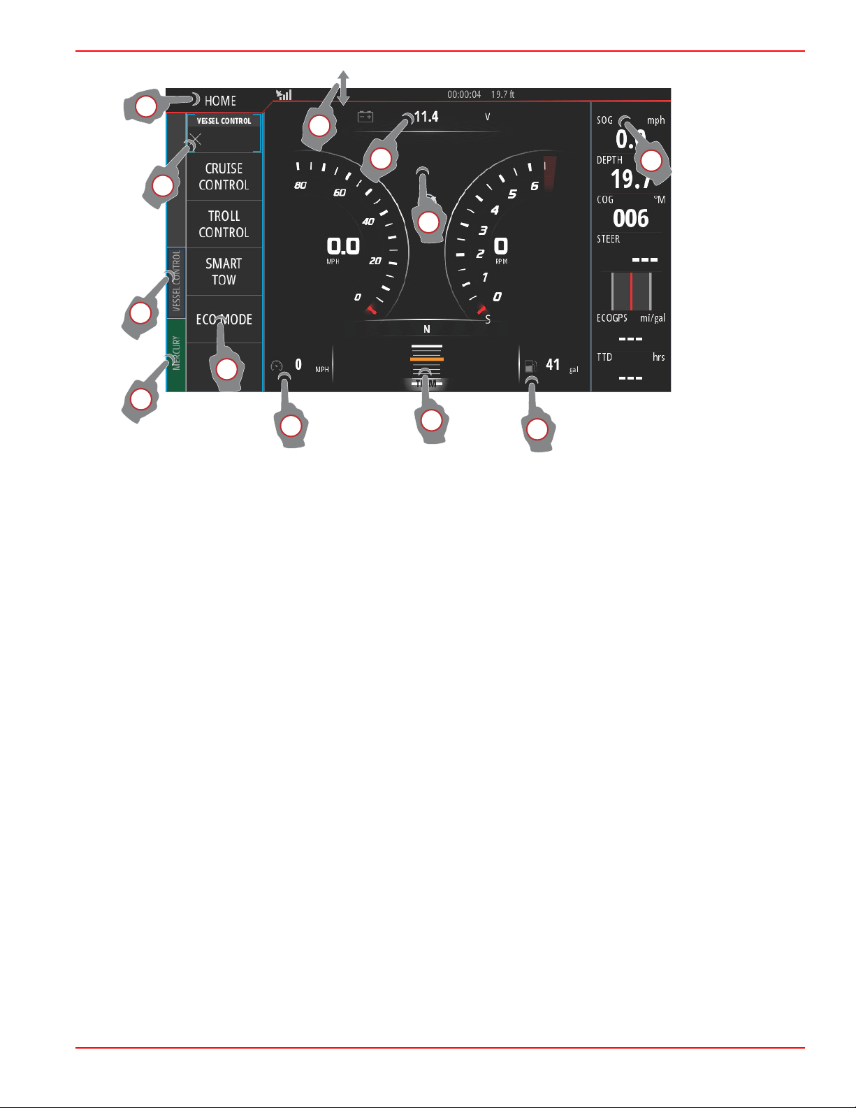
a - A downward swipe from outside the touch screen, into the touch screen will bring up the System Controls menu. From
here, users can set and adjust the System Settings, Standby mode, Brightness, Wireless options, and display the
Instrument Bar on the right‑hand side of the screen.
b - Touching this district of the screen will enlarge the data displayed.
c - Touching this district of the screen will further enlarge the data to fill the display area of the screen.
d - Touching this district, with the Instrument Bar active will allow the user to modify or customize the data displayed in the
Instrument Bar. Above the Instrument Bar will appear a MENU tab. In the MENU tab users can turn on or off the Autopilot
and Audio tile, define the data in Bar 1 and Bar 2, Animate and define the duration cycle of the data animation, and edit
data display selections.
e - Touching this district of the screen will enlarge the data on‑screen.
f - Touching this district of the screen will enlarge the trim and tab data on‑screen.
g - Touching this district of the screen will enlarge the data on‑screen.
h - Touching any of the tiles in this district of the screen will open the autopilot feature selected.
i - Touching the Mercury tab will display engine and vessel data on the left‑hand side of the screen. This is helpful when the
main screen is populated with autopilot data screens or being used to enlarge a specific data display.
j - Touching the Vessel Control tab will bring up the autopilot features associated with VesselView. Selections include: Cruise
Control, Troll Control, Smart Tow, and ECO Mode.
k - Touching the X will collapse the Vessel Control panel.
l - Touching the HOME tab will take the user to the main HOME screen of the VesselView unit. This screen shows the user
the Navico® side of the MFD and its features, options, and settings menus. VesselView can be started by touching the
Mercury Tile on this screen.
90-8M0109374 eng JUNE 2016 Page 5
Page 11
Section 1 - Getting Started
abc
61823
a
b
61820
c
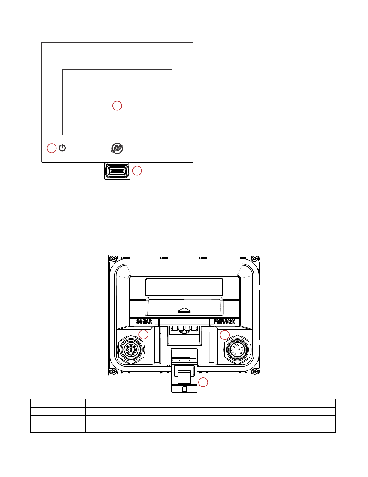
VesselView 502 Front Controls
a - Touch screen
b - Micro SD card port
c - Power‑brightness
VesselView 502 Front Control Operations
Touch screen: The screen on VesselView 702 has numerous districts that are touch sensitive and operated with a touch, or
with a vertical or horizontal swipe.
Micro SD card port: Allows VesselView software to be upgraded, to have navigation charts uploaded, and waypoints and
settings to be saved.
Power‑brightness: Press once to display the System controls dialogue. Repeat short presses to cycle the backlight
brightness. Press and hold to turn the unit ON/OFF.
VesselView 502 Rear Panel Connections
Item
a Power/NMEA 2K Provides the power connection/connects to NMEA 2K network
b Micro SD card port Allows file transfers and file saving
c Sonar Provides a sonar input
Function Description
Page 6 90-8M0109374 eng JUNE 2016
Page 12
Section 1 - Getting Started
a
61396
STBY
AUTO
bcd
e
f
g
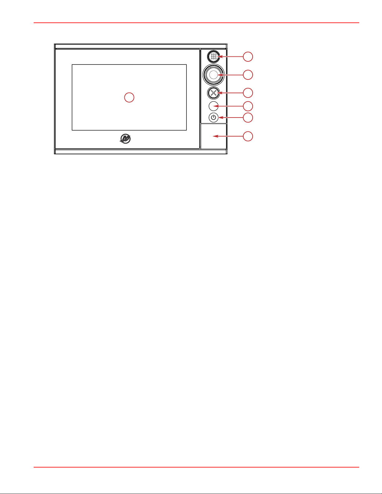
VesselView 702 Front Controls
a - Touch screen
b - HOME button
c - Rotary knob
d - X button
e - Standby/Auto button
f - Power‑brightness
g - Micro SD card port
VesselView 702 Front Control Operations
Touch screen: The screen on VesselView 702 has numerous districts that are touch sensitive and operated with a touch, or
with a vertical or horizontal swipe.
HOME: Press once to activate the Home page. Repeat short presses to cycle the favorite buttons. Press and hold to display
the Favorite panel as an overlay on active page. Repeat short presses to cycle the favorite buttons.
Rotary knob: Rotate to scroll through menu items, then press to confirm a selection. Rotate to adjust a value. Rotate to zoom a
zoomable panel.
X: Press once to exit a dialogue, to return to previous menu level, and to remove the cursor from the panel.
STBY/AUTO: With the autopilot in any automatic mode: press to set the autopilot to Standby mode. With the autopilot in
Standby mode: press to display the autopilot mode selection pop‑up.
Power‑brightness: Press once to display the System controls dialogue. Repeat short presses to cycle the backlight
brightness. Press and hold to turn the unit ON/OFF.
Micro SD card port: Allows VesselView software to be upgraded, to have navigation charts uploaded, and waypoints and
settings to be saved.
90-8M0109374 eng JUNE 2016 Page 7
Page 13
Section 1 - Getting Started
61397
abc
d
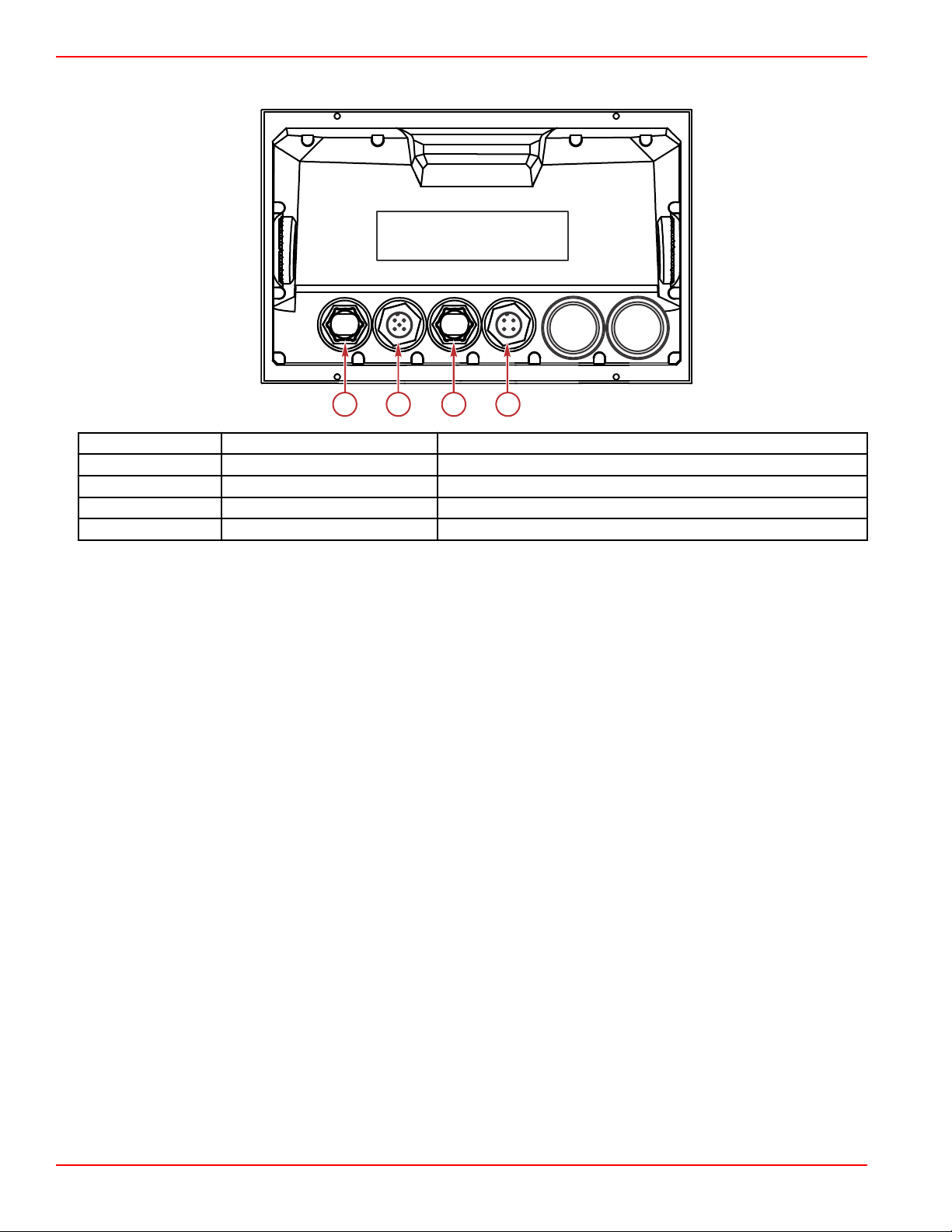
VesselView 702 Rear Panel Connections
Item Function Description
a Ethernet Connects to an Ethernet network
b NMEA 2K Connects to NMEA 2K network
c Video in Provides two composite video inputs
d Power Provides the power connection
VesselView Link Overview
VesselView Link integrates a Mercury‑powered boat’s SmartCraft data and control system with specific Simrad and Lowrance
instruments, providing a fully functional Mercury VesselView user interface on those units' displays. Available as a
single‑engine or multiengine (two to four engines) interface, Mercury VesselView Link easily installs beneath the boat's dash. It
is engineered to work with the following instruments:
• VesselView 502
• VesselView 702
• Simrad NSS evo2
• NSO evo2 marine processors
• Lowrance HDS Gen 2 Touch
• Lowrance HDS Gen 3 fish finder/chartplotters
Mercury’s new VesselView Link provides the user with instant access to advanced Mercury SmartCraft features, including:
• ECO mode
• Troll Control in 10‑RPM increments
• Cruise Control—RPM or speed‑based
• Smart Tow tow sport launch control system—RPM or speed‑based, with customizable user launch profiles and a new
intuitive interface
• Descriptive fault text for any potential propulsion issue available in 16 user‑selectable languages.
Page 8 90-8M0109374 eng JUNE 2016
Page 14

VesselView Link Connections
61413
abc
61828
Section 1 - Getting Started
a - NMEA 2K connection
b - SmartCraft/power connection
c - Micro SD card port
Safe Boating Screen
Each time that VesselView is powered on, after a complete shutdown of 30 seconds or more, a screen containing advisories
regarding boating safety is displayed to the operator. Touch the Accept button to continue.
How to Update Your VesselView Software
There are two ways that the VesselView software can be updated.
Wi‑Fi Automatic Query
The VesselView 502 is equipped with a wi‑fi module and Bluetooth connectivity. When powered up, the unit will periodically
query the internet to determine if there is an update file available from the Mercury Marine website. A screen notification to
confirm updates, and will prompt the operator to accept an update.
90-8M0109374 eng JUNE 2016 Page 9
Page 15
Section 1 - Getting Started
61450
61451
The VesselView 702 has internet connectivity, but must be in the range of a wi‑fi hotspot, or mobile device set up to be a wi‑fi
hotspot, in order to query the internet for any updates on the Mercury Marine website. If an update is detected, a screen prompt
will guide the operator through the update process.
Using the Micro SD Card
The following instructions explain how to upgrade the VesselView software. Internet access is required to download the version
update file from the Mercury website. The ability to transfer the update file to a FAT or FAT 32 micro SD card is also required.
1. Turn the ignition key on and verify that the VesselView is on.
2. Insert the micro SD card into the VesselView micro SD card port all the way until it clicks and stays in place.
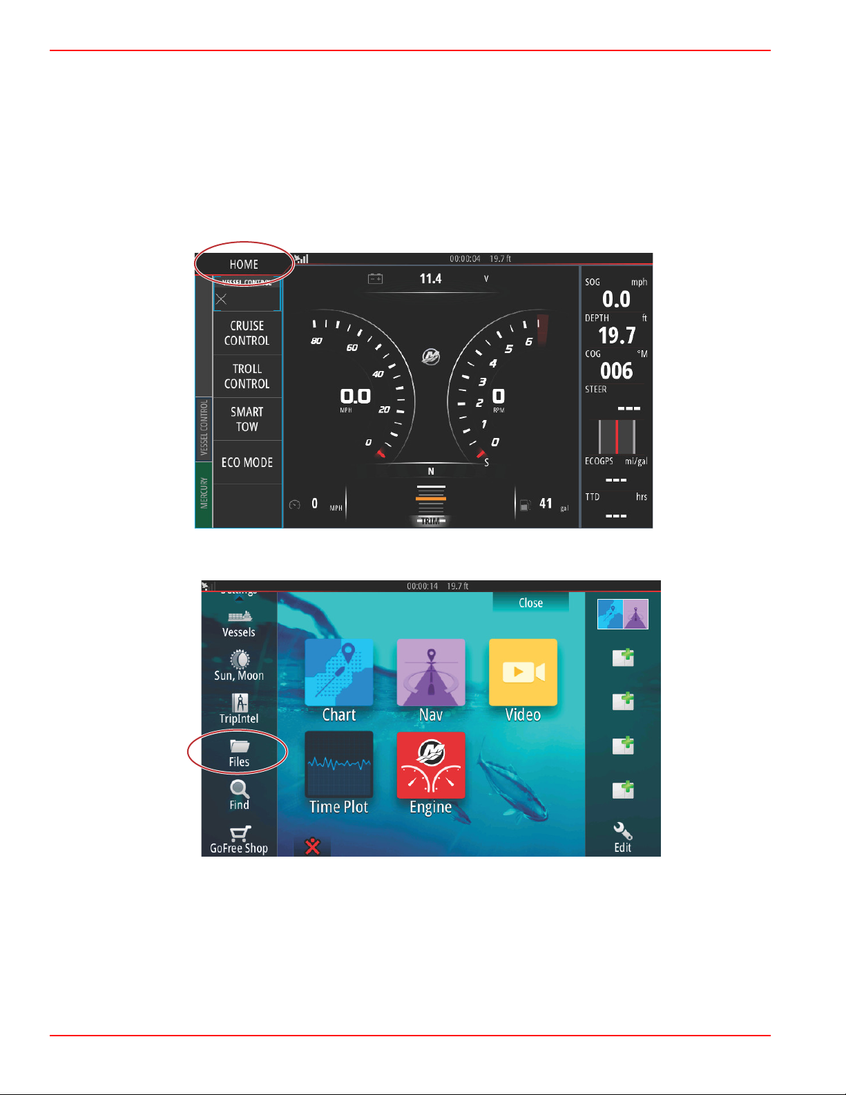
3. Touch the HOME tab at the top of the screen to bring up the Home screen.
4. On the Home screen, swipe the left‑hand side window to the Files icon.
Page 10 90-8M0109374 eng JUNE 2016
Page 16
Section 1 - Getting Started
61453
61455
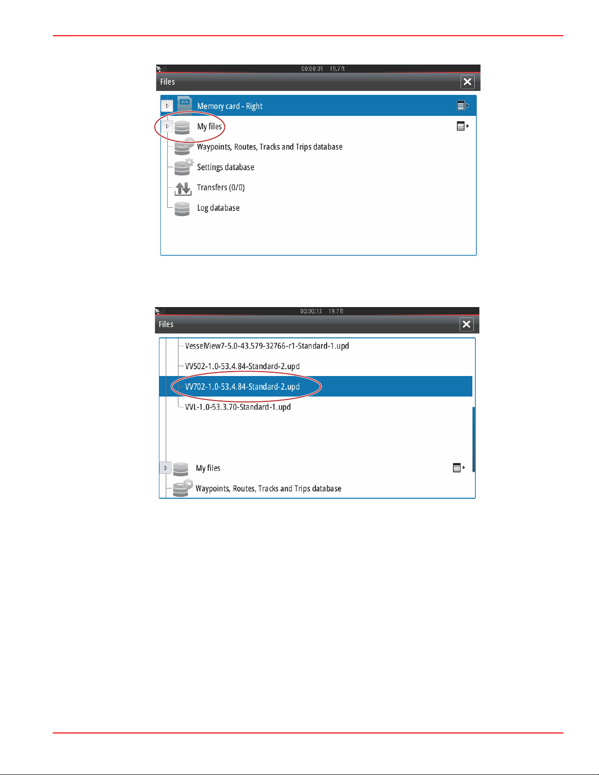
5. Select My files from the options shown.
6. Select the file that was downloaded from the Mercury website. The file shown in the following image is for illustrative
purposes only, and does not represent the actual file name that you will be selecting.
90-8M0109374 eng JUNE 2016 Page 11
Page 17
Section 1 - Getting Started
61456
61458
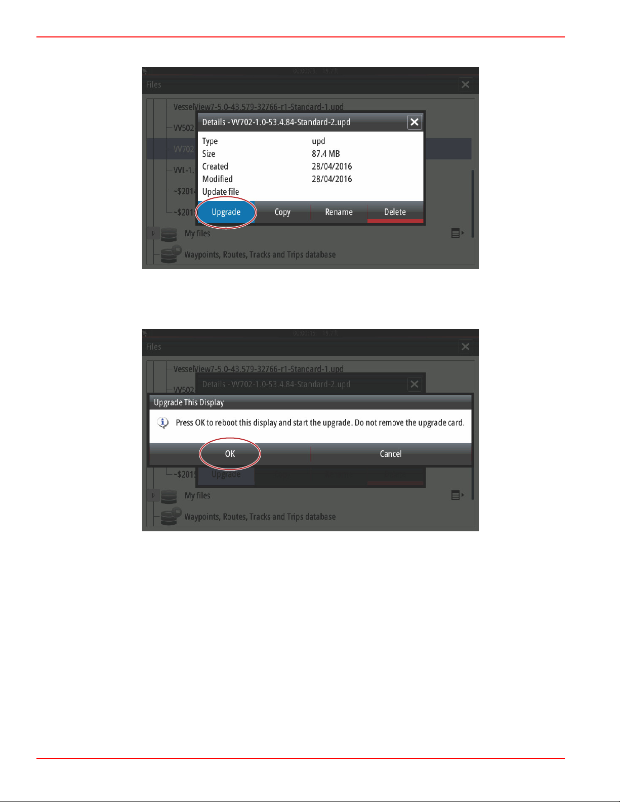
7. Select the Upgrade option in the Details window.
8. Select OK in the Upgrade This Display window. VesselView will display a progress bar, showing the upgrade progress. Do
not power off the display during this step in the upgrade. VesselView will briefly display a Restarting screen. Following the
rebooting process, the VesselView will be ready for operation with the upgraded software.
Page 12 90-8M0109374 eng JUNE 2016
Page 18
Section 1 - Getting Started
61469
61470
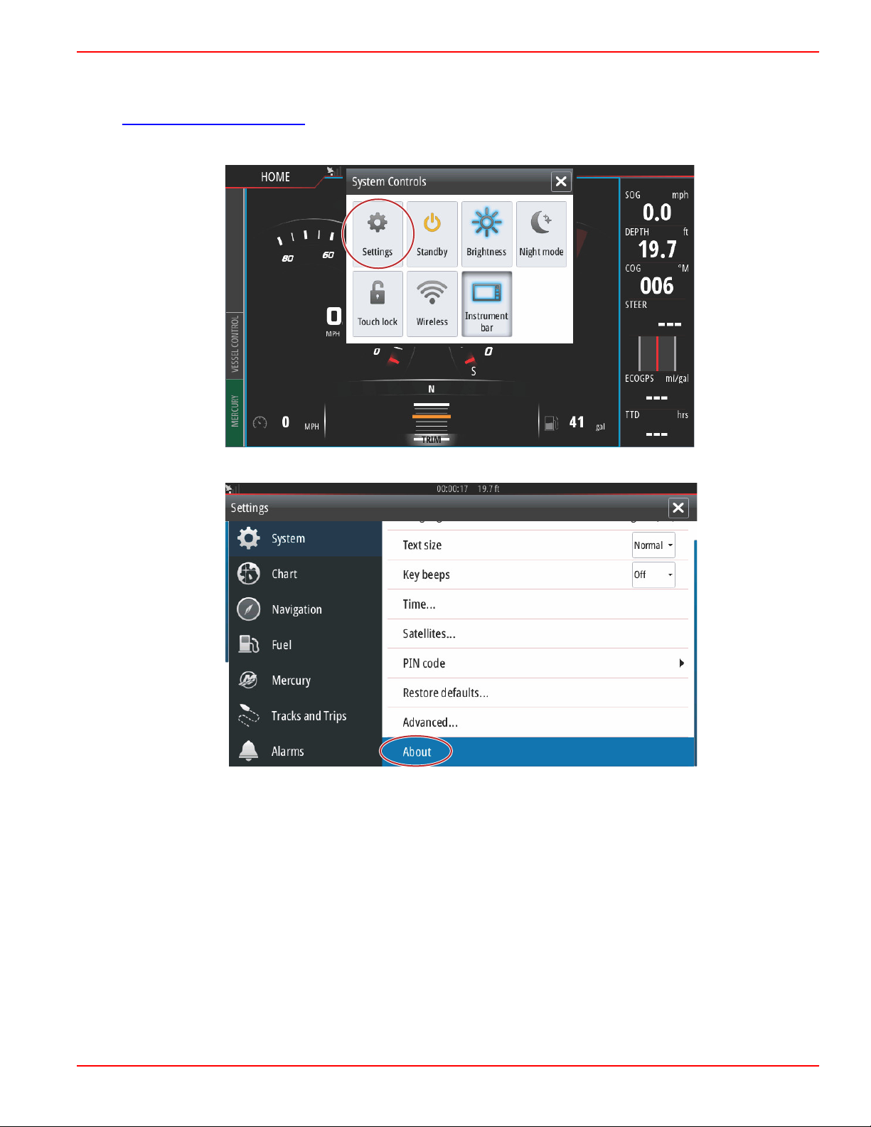
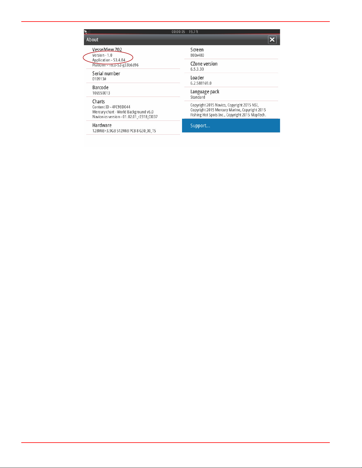
Obtaining the Latest Software
1. The latest software for the VesselView and the Link Module is available on‑line for general download at Mercury's website;
https://www.mercurymarine.com. To understand what software version is in VesselView, power up VesselView. If
VesselView is already powered up, swipe from the top of the unit down onto the screen to bring up the System Controls
menu. Select Settings>System>About to see the current operating version of VesselView software.
90-8M0109374 eng JUNE 2016 Page 13
Page 19
Section 1 - Getting Started
61471
2. Select the VesselView product and click on Download VesselView Update.
3. Depending on your computer’s security settings, a security warning may appear. Click Allow to continue.
4. Create a folder on your hard drive and save the file in this folder.
5. If you are asked to SAVE or RUN, select SAVE and save to your hard drive.
NOTE: The file is typically 80‑90 MB in size.
IMPORTANT: Some browsers may change the file extension. Verify that the filename and extension have not changed.
The correct extension after the filename should be .upd. Do not rename the file or change the extension.
6. After the file is saved to the hard drive, copy the file to a 512 MB or higher capacity blank FAT or FAT 32 micro SD card
root. The root of the drive is the topmost level, where the file is not placed into a folder.
How to Update Your VesselView Link Module Software
The VesselView Link Module can be updated through the VesselView unit. VesselView Link Module software updates can be
found on the Mercury website, on the same screen that the VesselView software updates are located. See How to Update
Your VesselView Software.
The following instructions explain how to upgrade the VesselView software. Internet access is required to download the version
update file from the Mercury website. The ability to transfer the update file to a FAT or FAT 32 micro SD card is also required.
NOTE: The file is typically 30 MB in size.
1. Turn the ignition key on and verify that the VesselView is on.
Page 14 90-8M0109374 eng JUNE 2016
Page 20
Section 1 - Getting Started
61459
abc
61828
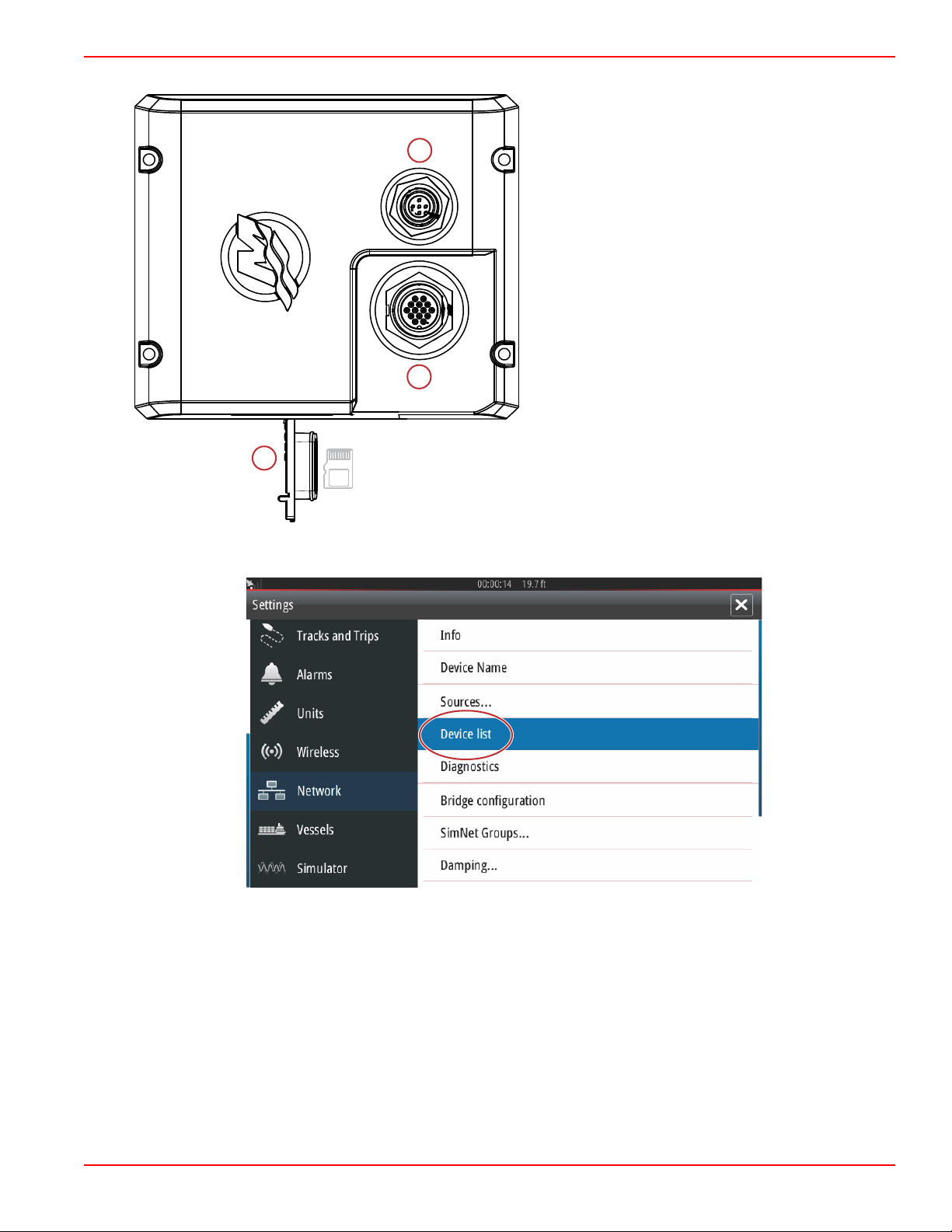
2. Insert the micro SD card into the VesselView Link Module micro SD card port all the way until it clicks and stays in place.
a - NMEA 2K connection
b - SmartCraft/Power connection
c - Micro SD card port
3. Touch the HOME tab at the top of the screen to bring up the Home screen. Navigate to the Settings option in the left‑hand
window. Select the Network Option. Select Device list.
90-8M0109374 eng JUNE 2016 Page 15
Page 21

Section 1 - Getting Started
61460
61461
4. Select the VesselView Link Module from the list of available devices. The following image is for illustrative purposes only,
your VesselView Link Module may show as Single, for a single‑engine application.
5. Select the Configure option.
Page 16 90-8M0109374 eng JUNE 2016
Page 22
Section 1 - Getting Started
61463
61840
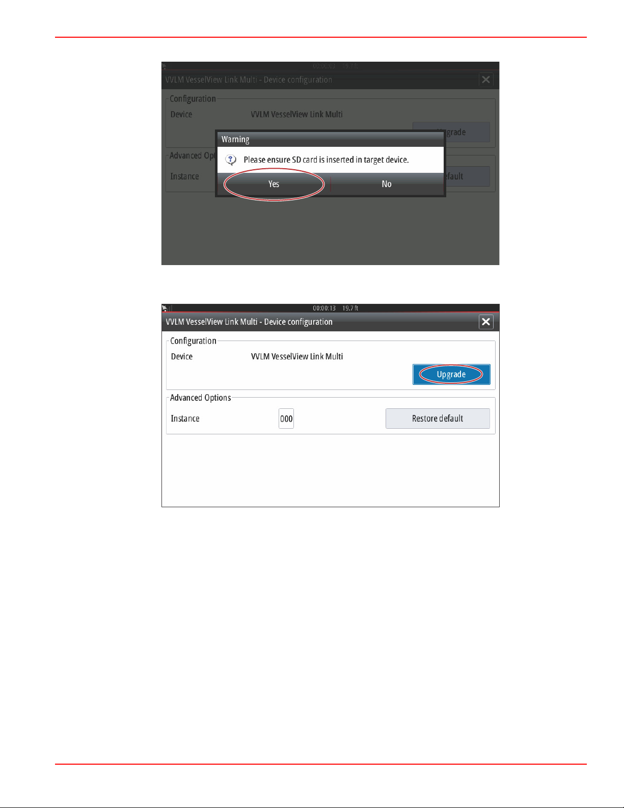
6. Confirm that the SD card is properly inserted in the VesselView Link Module, and select the Yes option.
7. Select the Upgrade option in the Device configuration window.
90-8M0109374 eng JUNE 2016 Page 17
Page 23
Section 1 - Getting Started
61465
61472
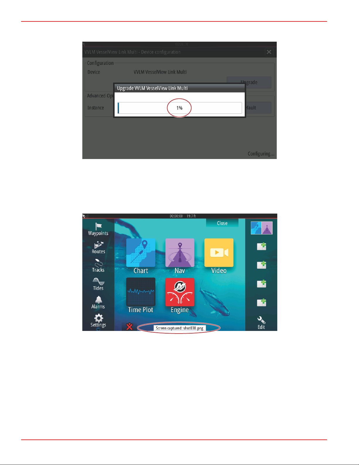
8. VesselView will display a progress bar, showing the VesselView Link Module upgrade progress. Do not power off the
display during this step in the upgrade.
Creating Screen Captures
VesselView has the ability to capture complete screens and store them for download to a SD card. When the unit is powered
up and the capture of a screen is wanted, press the Power button and the Home button at the same time. A notification tab will
appear on the bottom of the screen, containing the image number of the screen capture. This notification tab will not be present
on the captured screen.
Page 18 90-8M0109374 eng JUNE 2016
Page 24
Section 1 - Getting Started
61473
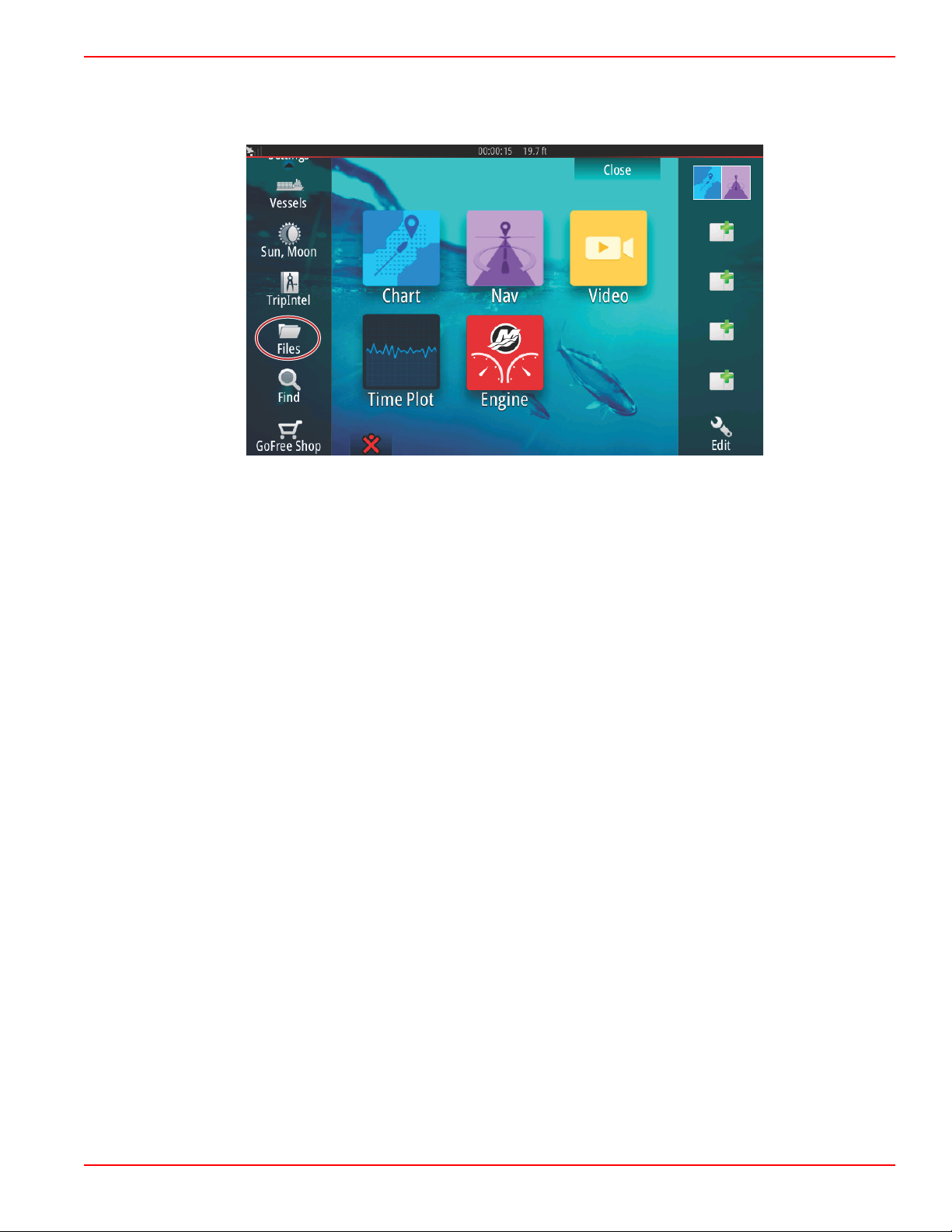
VesselView has an internal memory capacity for up to 32 screen captures. It is recommended that files such as screen
captures, waypoints, tracks, and routes be backed up on an SD card or other external storage device, and the internal memory
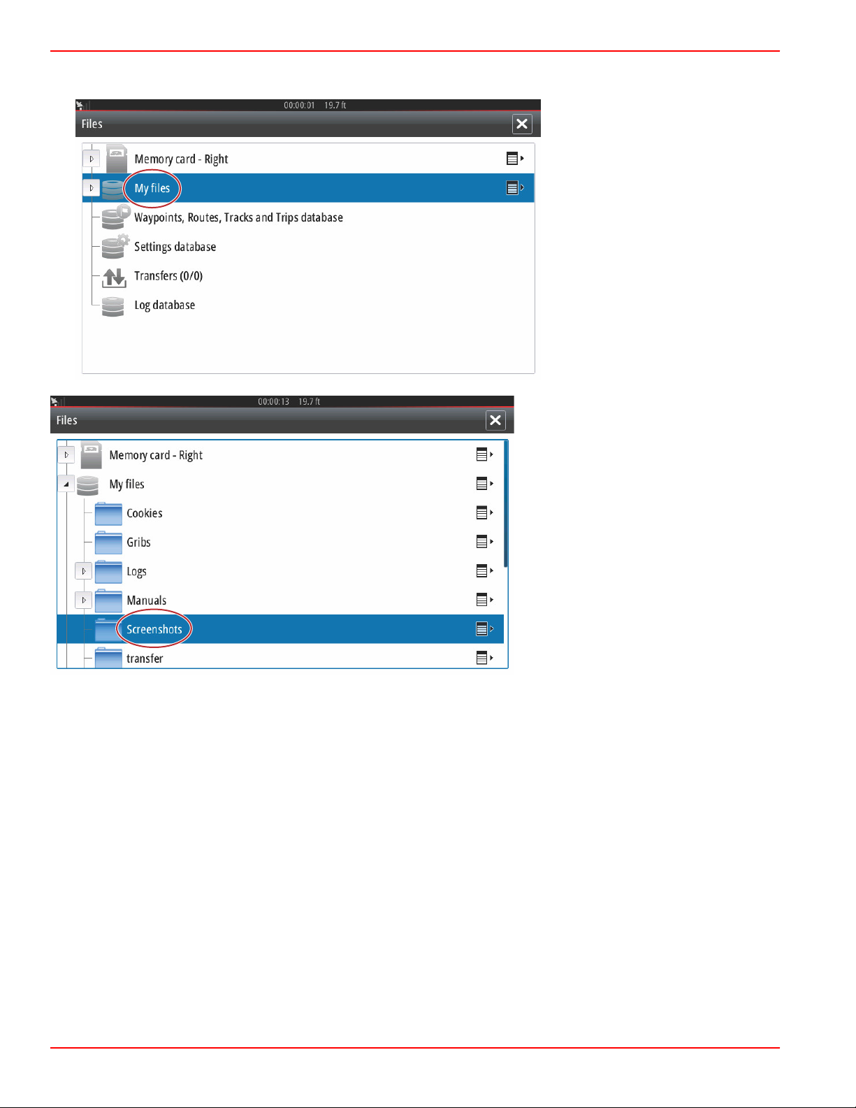
kept as clear as possible. By default, all of the screen captures are stored in a Screenshots folder in My Files. The My Files
folder can be accessed by swiping from the top of the unit onto the screen to bring up the left‑hand side options. Select Files.
90-8M0109374 eng JUNE 2016 Page 19
Page 25
Section 1 - Getting Started
61474
61475
Open the My files folder and navigate to the Screenshots folder. In the Screenshots folder, all of the screenshots that were
captured will display. Shots can be copied to the SD card for transfer to a computer or mobile device.
Page 20 90-8M0109374 eng JUNE 2016
Page 26

Section 1 - Getting Started
61476
61477
Individual screenshots can be accessed by selecting them. All screenshots can be accessed at once using the icon on the
right‑hand side of the files window. Selecting this icon will allow viewing of the screenshot details, copying all the screenshots,
or deleting all of the screenshots.
90-8M0109374 eng JUNE 2016 Page 21
Page 27
Section 1 - Getting Started
61479
61480
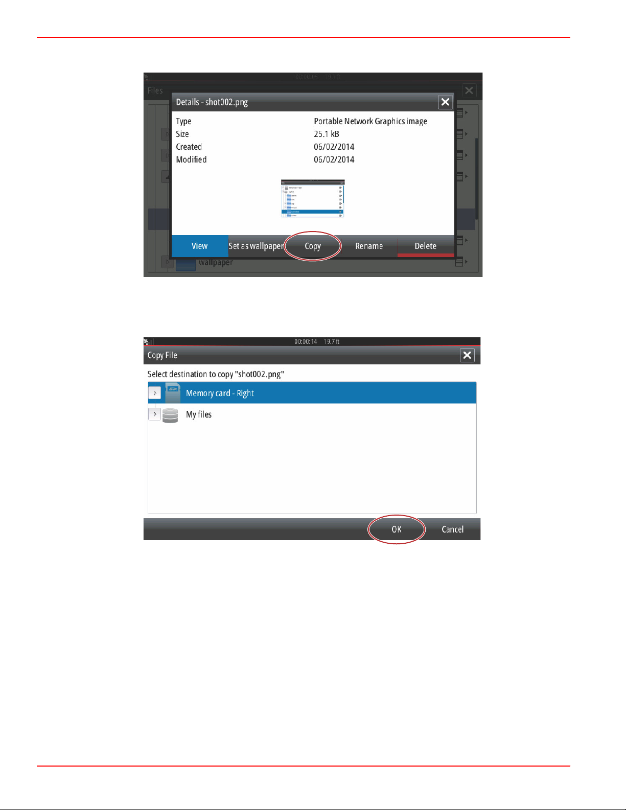
If an individual screenshot is selected, a window will appear with options to View, Set as wallpaper, Copy, Rename, or Delete.
Select Copy to download the image from the VesselView.
With a SD card loaded into the VesselView, select Memory card as the destination for the file and select OK. Close the window
by selecting the X in the upper right corner. This will take you back to the Screenshots folder. To download additional images,
follow this procedure.
Page 22 90-8M0109374 eng JUNE 2016
Page 28
Section 1 - Getting Started
61481
61482
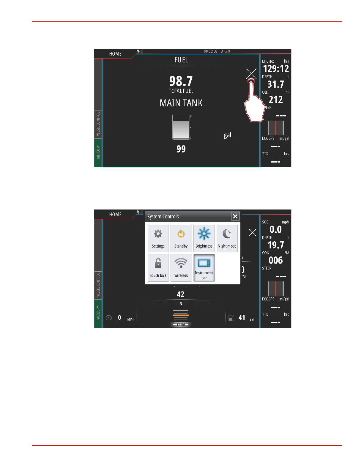
Non‑Mercury Marine Menus
Operators may find themselves out of the recognizable Mercury Marine screens of the VesselView. These menus and options
are referred to as the Navico® side of VesselView. Mercury Marine does not support these components of the unit. For
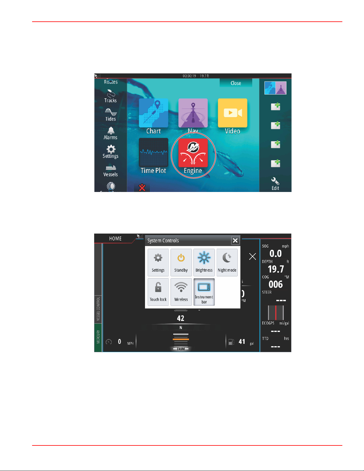
additional information on this side of the VesselView, please contact Navico®. To get back to the navigation screens of the
Mercury Marine side of the unit, press the Home button, and the Mercury Engine tile will appear. Select this tile to return to the
VesselView screen.
The System Controls window can be brought up by swiping from the top of the unit onto the screen. This will allow the user to;
utilize the Mercury Settings menu, place the unit in Standby mode, adjust the brightness of the screen, run in night mode,
engage the Touch lock feature, customize wireless connectivity, and activate the instrument bar on the right‑hand side of the
display.
90-8M0109374 eng JUNE 2016 Page 23
Page 29

Section 1 - Getting Started
61483
61493
Within the Settings menu in the System Controls window, select the Mercury icon to make changes to VesselView functions. All
of the preferences and settings that pertain to VesselView are contained within the Mercury settings. All other menu options
pertain to the Navico® side of the MFD. Any inquiries regarding these features should be directed to Navico®.
Touch Screen Calibration
The touch screen can be calibrated periodically. If swipes or touch districts seem unresponsive, activate the System Controls
menu by swiping from the top of the unit onto the screen. Select the Settings option. Select the Advanced option. Select the
Hardware menu option to bring up the Touchscreen calibration menu item.
Page 24 90-8M0109374 eng JUNE 2016
Page 30

Section 1 - Getting Started
61494
61496
VesselView will prompt the operator to confirm Touchscreen Calibration. To continue with the calibration, select Calibrate.
It is important that the screen is not touched during the calibration process.
90-8M0109374 eng JUNE 2016 Page 25
Page 31

Section 1 - Getting Started
61499
61486
A progress bar will be displayed, showing the operator that the process is taking place. After completing the calibration, the
display will return to the Advanced Settings menu.
Start‑up
On start‑up with the power on and engines off, after the splash screen and advisory screen sequence, the main display will load
and all data and graphics will be active.
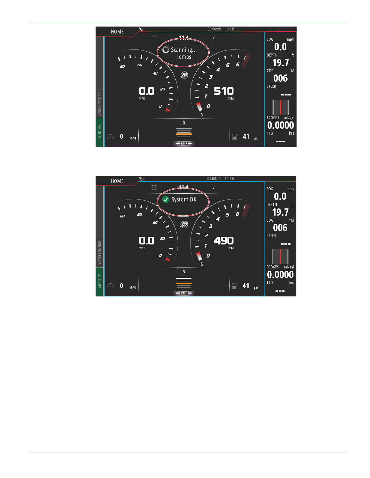
Upon engine start‑up, the VesselView will perform a systems check. All engine systems will be queried for current operational
data. The systems check appears visually on the screen between the speed and/or RPM sweeps.
Page 26 90-8M0109374 eng JUNE 2016
Page 32
Section 1 - Getting Started
61487
61488
After the systems check, if all engine parameters are within specifications, the VesselView will display the System OK message
accompanied by a checkmark icon.
90-8M0109374 eng JUNE 2016 Page 27
Page 33

Section 1 - Getting Started
61541
61536
If an engine system does not pass the systems check, short descriptive fault text will appear, and a suggested course of action
will be displayed on‑screen. The Mercury tab in the lower left‑hand corner of the screen will display in red with international
warning symbol. If there is more than one fault detected at start‑up, the operator can scroll through the list, highlight a selection
and select Details.
Selecting Details will bring up a window that may have additional fault descriptive text, telling the operator if the fault is critical,
noncritical, and what to do about the fault.
Engine Scheduled Maintenance
If a maintenance reminder is detected during a system scan, the Mercury tab in the lower left‑hand corner of the screen will
display in the color blue. Use common sense to protect your investment, and check your engine oil on a regular basis,
preferably before each use.
When the scheduled maintenance time is fully depleted, a maintenance pop‑up will appear after the start‑up scan. The operator
can close the pop‑up, but the reminder will appear at every key‑on of the vessel. Acknowledgement of the maintenance
reminder will reset the maintenance time frame in VesselView. To access the specific information regarding scheduled
maintenance navigate to the descriptive maintenance text message using the following instructions. Users can view the
maintenance bar at any time to view the depletion status. This can help in scheduling future appointments with your dealer, if
the maintenance is not performed by the owner.
Select the Mercury tab in the lower left‑hand corner of the screen. Select the Mercury icon with the word MORE.
Page 28 90-8M0109374 eng JUNE 2016
Page 34

Section 1 - Getting Started
61538
61539
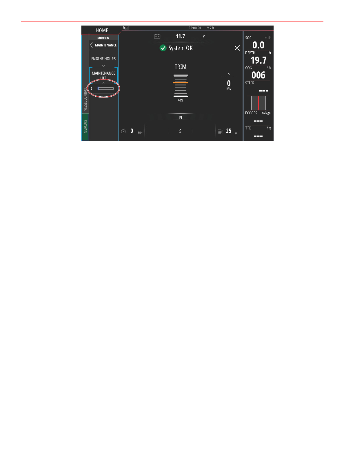
Select the MAINTENANCE option.
To view the remaining time before scheduled maintenance, select the MAINTENANCE LIFE option. The more of the progress
bar shown in blue, the sooner scheduled maintenance is needed.
90-8M0109374 eng JUNE 2016 Page 29
Page 35
Section 1 - Getting Started
61540
Device Maintenance
IMPORTANT: It is recommended that the supplied white plastic sun cover be installed for protection when the unit is not in
service.
Display Screen Cleaning
Routine cleaning of the display screen is recommended to prevent a buildup of salt and other environmental debris. Crystalized
salt can scratch the display coating when using a dry or damp cloth. Ensure that the cloth has a sufficient amount of fresh water
to dissolve and remove salt deposits. Do not apply aggressive pressure on the screen while cleaning.
When water marks cannot be removed with the cloth, mix a 50/50 solution of warm water and isopropyl alcohol to clean the
screen. Do not use acetone, mineral spirits, turpentine type solvents, or ammonia based cleaning products. The use of strong
solvents or detergents may damage the antiglare coating, the plastics, or the rubber keys.
It is recommended that the sun cover be installed when the unit is not in use to prevent UV damage to the plastic bezels and
rubber keys.
Media Port Cleaning
The media port door area should be cleaned on a regular basis to prevent a buildup of crystalized salt and other debris.
Page 30 90-8M0109374 eng JUNE 2016
Page 36

Section 2 - Initial Screens and Setup Wizard
Table of Contents
Section 2 - Initial Screens and Setup Wizard
VesselView Start‑up Advisory Screen.................................. 32
Splash Screen...................................................................... 32
Setup Wizard........................................................................ 33
Import Configuration ..................................................... 35
Engine Setup ................................................................ 35
Display Setup ............................................................... 39
Device Setup ................................................................ 40
Units Setup ................................................................... 40
Tank Configuration ....................................................... 40
Speed Setup ................................................................. 43
Finishing Setup Wizard ................................................. 44
Data Source Setup............................................................... 44
Data Sources ................................................................ 44
Enlarging Data Screens........................................................ 46
Instrument Bar...................................................................... 47
2
90-8M0109374 eng JUNE 2016 Page 31
Page 37

Section 2 - Initial Screens and Setup Wizard
61413
61484
VesselView Start‑up Advisory Screen
When VesselView is started, a warning screen pops up and advises the operator not to rely on the product as a primary source
of navigation and that the user assumes all liability for operation and associated risks.
Splash Screen
When the ignition key is turned on, a Mercury start‑up splash screen will appear. The Mercury logo will appear in the center of
the screen. The logo will remain during the start‑up process. Do not try and rush the unit by pressing buttons during the start‑up
stage. Power packages with emissions control will show an engine icon in the lower left‑hand corner of the screen.
Page 32 90-8M0109374 eng JUNE 2016
Page 38

Section 2 - Initial Screens and Setup Wizard
61504
61505
Setup Wizard
The VesselView Setup wizard guides you through the first steps of configuring the VesselView. The Setup wizard can be
accessed at any time through the Settings menu. Open the System Controls window. The System Controls window can be
brought up by swiping from the top of the unit onto the screen. Select the Settings tile.
Select the Mercury option on the left‑hand side of the screen. Select the System option.
90-8M0109374 eng JUNE 2016 Page 33
Page 39

Section 2 - Initial Screens and Setup Wizard
61506
61507
In the System menu, select the Setup wizard option.
On the Device Configuration WELCOME screen select Next to begin the Setup wizard.
Page 34 90-8M0109374 eng JUNE 2016
Page 40

Section 2 - Initial Screens and Setup Wizard
61508
61509
Import Configuration
To import an existing vessel configuration, insert a FAT or FAT 32 micro SD card with the configuration file and select this file in
the drop‑down menu. If there is no import file, select Next to continue.
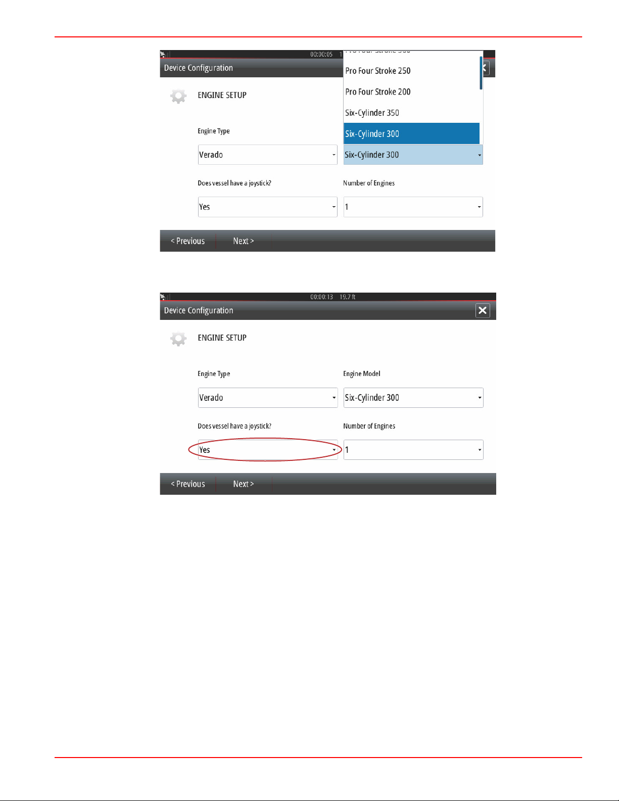
Engine Setup
1. In the Engine Setup screen, use the rotary knob or touch the menu fields to select the correct option.
2. Complete selections in the Engine Setup screen. When finished making selections, select Next to continue.
Engine type
90-8M0109374 eng JUNE 2016 Page 35
Page 41

Section 2 - Initial Screens and Setup Wizard
61510
61515
Selection
Engine model
Page 36 90-8M0109374 eng JUNE 2016
Page 42
61512
Selection
61516
Section 2 - Initial Screens and Setup Wizard
Joystick vessel
90-8M0109374 eng JUNE 2016 Page 37
Page 43

Section 2 - Initial Screens and Setup Wizard
61514
61517
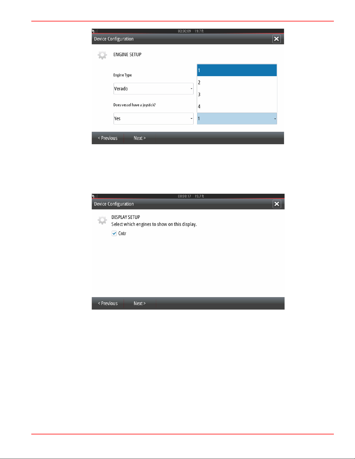
Selection
Number of engines
Page 38 90-8M0109374 eng JUNE 2016
Page 44
Section 2 - Initial Screens and Setup Wizard
61513
61522
Selection
Display Setup
Depending on the number of engines indicated in the Engine Setup screen, select the engines to be displayed by this
VesselView unit. Up to four engines can be selected. Select Next to continue.
90-8M0109374 eng JUNE 2016 Page 39
Page 45
Section 2 - Initial Screens and Setup Wizard
61521
61523
a
b
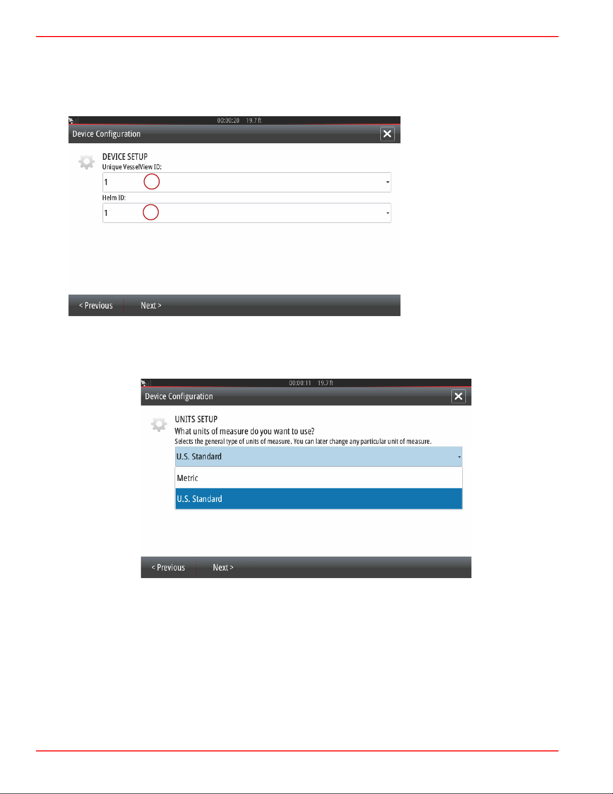
Device Setup
In the Device Setup screen, use the rotary knob or touch the menu fields to select the proper options. If using multiple
VesselView devices, be sure to assign unique numbers to each unit, to avoid data problems. Helm numbers should match the
location of the individual VesselView unit. It is common to make the main helm 1 and the secondary helm 2. Select Next to
continue.
a - VesselView identification field
b - Helm identification field
Units Setup
Select the units of measure that VesselView will display on‑screen data; speed, distance, and volumes. Particular units of
measure can be changed later.
Tank Configuration
In the tank setup screen, tank type, capacity, and tank name can be assigned for up to 8 tanks. The % column will display the
live tank volume. Selecting the refresh button will query the tank sensors and refresh the readings.
The unmonitored tank is a tank that does not have a sensor associated with it.
Page 40 90-8M0109374 eng JUNE 2016
Page 46
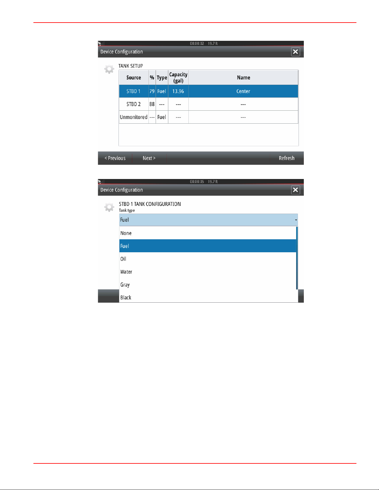
Select the tank row to be customized.
61524
61525
Section 2 - Initial Screens and Setup Wizard
Select the tank type
90-8M0109374 eng JUNE 2016 Page 41
Page 47
Section 2 - Initial Screens and Setup Wizard
61526
61528
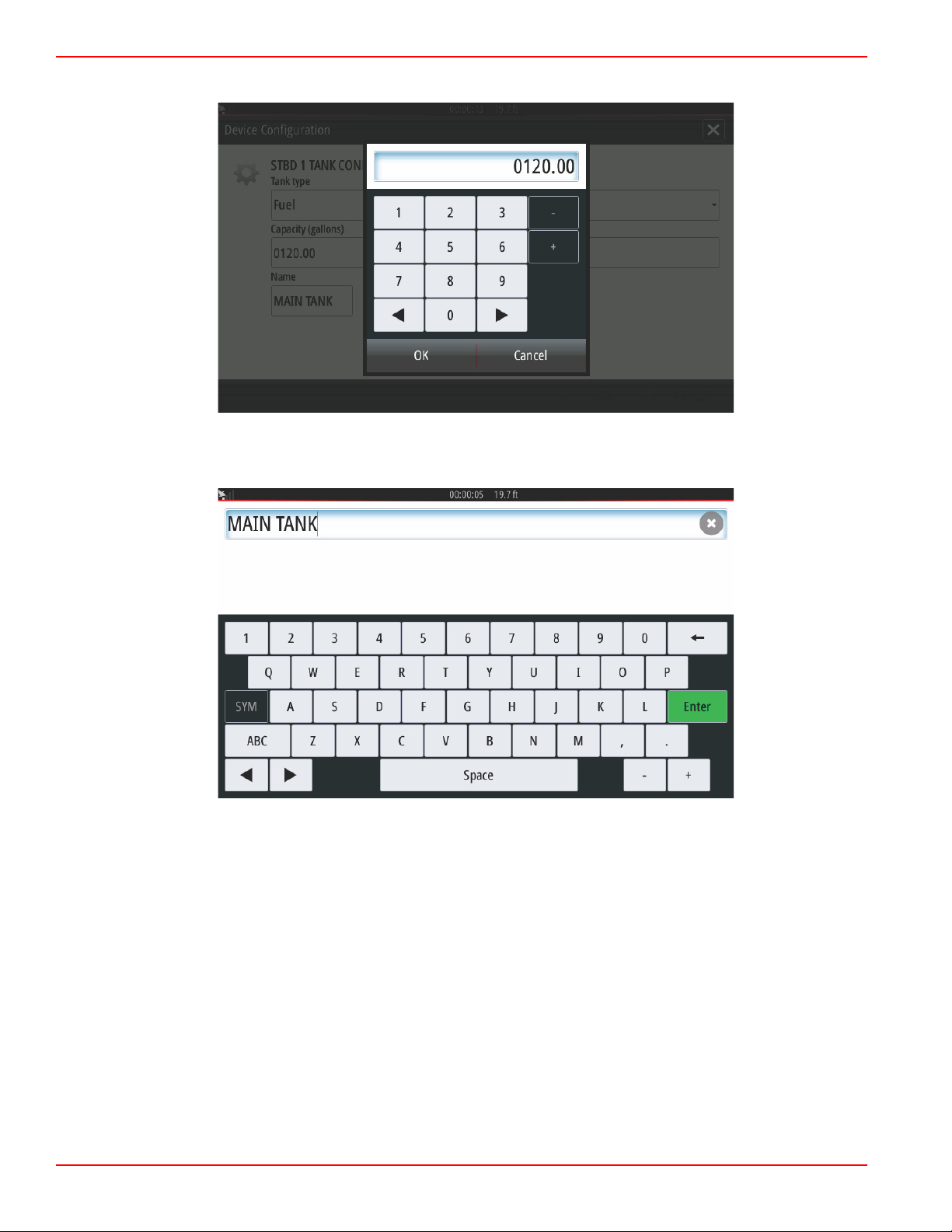
Use the on‑screen keypad to enter the capacity. When finished entering tank capacity data, select OK to close the keypad.
The tank position will populate the name field. To change the name of the tank, select the field and use the on‑screen keypad
to customize the tank name.
After entering a tank name, select Enter on the keyboard to continue to the next tank row in the Tank Setup screen. When all
tank customization data has been entered, select the Refresh button in the lower corner. Check all data fields for accuracy, and
select Next to continue with the Setup wizard.
Page 42 90-8M0109374 eng JUNE 2016
Page 48

Section 2 - Initial Screens and Setup Wizard
61529
aaa
bbb
c
c
d
60056
a
Speed Setup
In the Speed Setup menus, there are three options for determining how VesselView will acquire speed information. If the vessel
is equipped with a GPS, the drop‑down menu will allow selection of available devices. If the vessel is equipped with a pitot
sensor, this option will be selected. If the vessel is equipped with a paddle wheel, then an option to select will drop‑down. After
the speed source has been selected, select Next to continue.
The pitot and paddle wheel source selection is shown in the following illustration. Select the engine or drive unit that transmits
the speed data to the VesselView.
a - PCM0 = starboard outer
b - PCM1 = port outer
c - PCM2 = starboard inner or center
d - PCM3 = port inner
90-8M0109374 eng JUNE 2016 Page 43
Page 49

Section 2 - Initial Screens and Setup Wizard
61530
61531
Sources
...
Finishing Setup Wizard
Select Finish to complete the Setup wizard on the VesselView. Do not power off the unit until the Finish screen is replaced by
the vessel activity screen.
Data Source Setup
Data Sources
To setup data sources, select the HOME tab at the top of the screen.
Power on all products and key on all engines to ensure that all data generating sources can be detected. Open the System
Controls window. The System Controls window can be brought up by swiping from the top of the unit onto the screen. Select
the Settings tile. Select the Network option on the left‑hand side of the screen. Select Sources... .
Page 44 90-8M0109374 eng JUNE 2016
Page 50
Section 2 - Initial Screens and Setup Wizard
61533
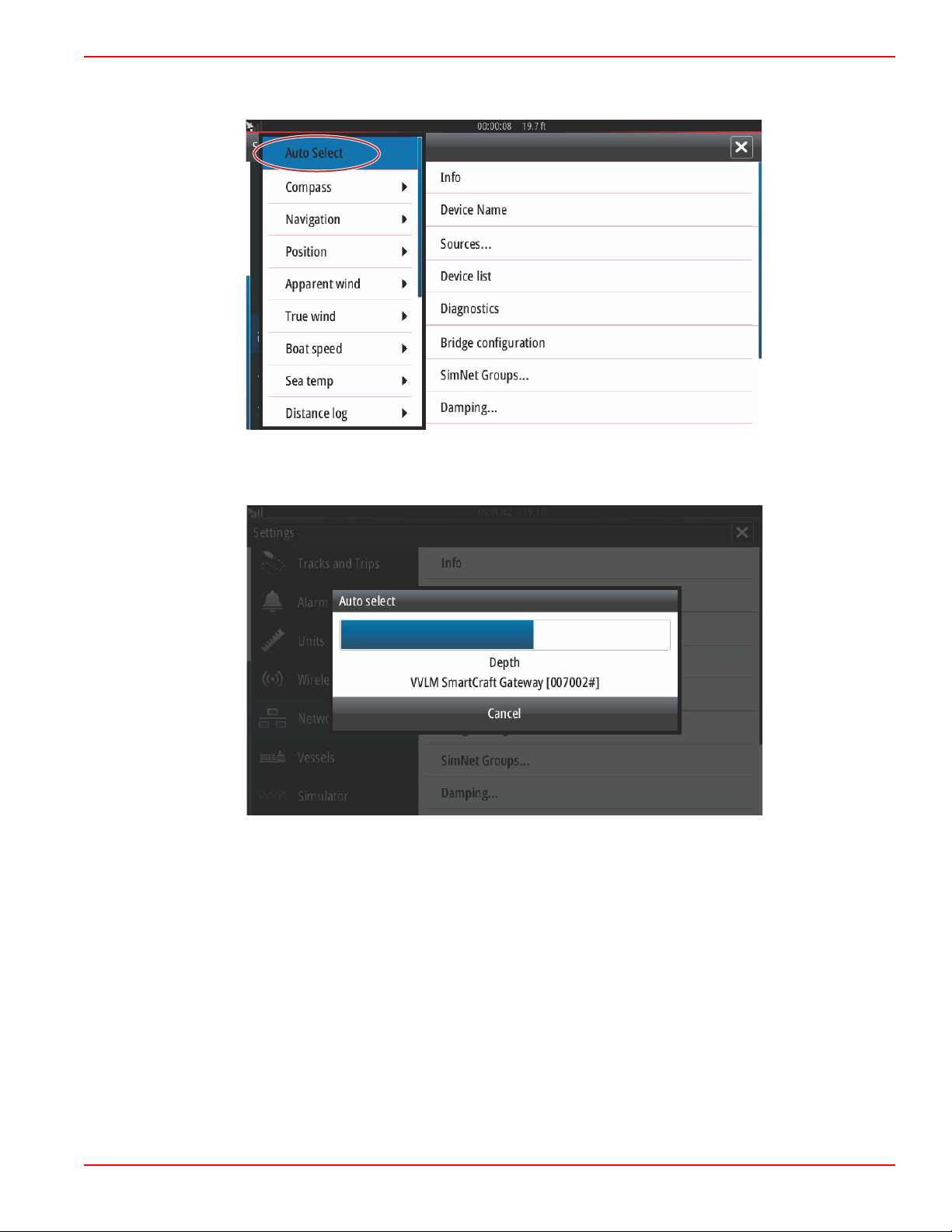
Auto Select
61534
VesselView will display numerous sources of data producing devices. For a general query of all detectable devices on the
vessel, select the Auto Select option at the top of the list.
Auto select will search the network and compile a list of all devices that are detected during the auto select process. When the
progress bar completes, the Settings menu can be closed by selecting the X in the upper right‑hand corner of the screen.
90-8M0109374 eng JUNE 2016 Page 45
Page 51
Section 2 - Initial Screens and Setup Wizard
61725
61726
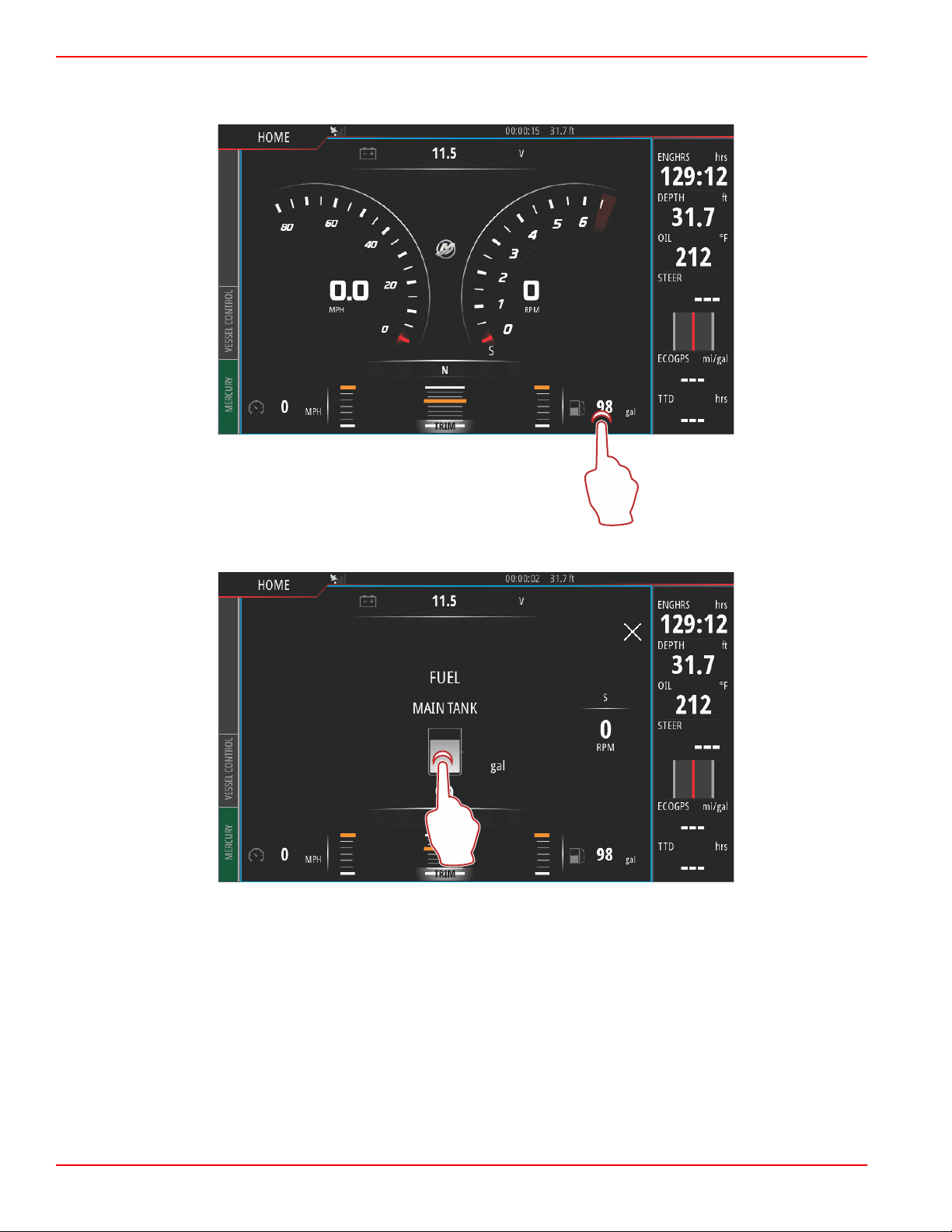
Enlarging Data Screens
To enlarge any of the data fields on the main VesselView screen, select the field.
This will display the data at it's medium size on the screen.
Page 46 90-8M0109374 eng JUNE 2016
Page 52
Section 2 - Initial Screens and Setup Wizard
61727
61482
Selecting the data info field once more will display the selected data full screen. This can be helpful for viewing the screen from
a greater distance, such as navigating from an auxiliary joystick position. Selecting the X will return the VesselView to the main
navigation screen.
Instrument Bar
To activate the Instrument bar, swipe from the top of the display screen into the top of the screen area. This will bring up the
System Controls window. Select the Instrument bar tile to activate the Instrument bar.
90-8M0109374 eng JUNE 2016 Page 47
Page 53

Section 2 - Initial Screens and Setup Wizard
61729
61730
The instrument bar is located on the right‑hand side of the display. The instrument bar contains text and numeric data in
numerous tiles. Each tile in the instrument bar can be changed by the operator. There are also boating lifestyle options that will
populate the data tiles with useful information for your type of boating.
To access the instrument bar, select the bar by touching anywhere within the instrument bar. This will bring up the MENU tab at
the top of the bar.
Page 48 90-8M0109374 eng JUNE 2016
Page 54

Section 2 - Initial Screens and Setup Wizard
61731
61732
In the menu screen, Bar 1 and Bar 2 options can be selected. These options will populate the instrument bar with engine and
vessel data that is important to the style of boating that is selected.
90-8M0109374 eng JUNE 2016 Page 49
Page 55

Section 2 - Initial Screens and Setup Wizard
61733
61734
The result of selecting General in Bar 1 and Fishing in Bar 2, populates the instrument bar with both general vessel and engine
data, as well as fishing pertinent data such as water temperature, live well temperature, and GPS coordinates.
Selecting Edit... in the MENU bar will give the operator the ability to select any of the data tiles and change the data content.
Page 50 90-8M0109374 eng JUNE 2016
Page 56
Section 2 - Initial Screens and Setup Wizard
61740
61735
a
b
b
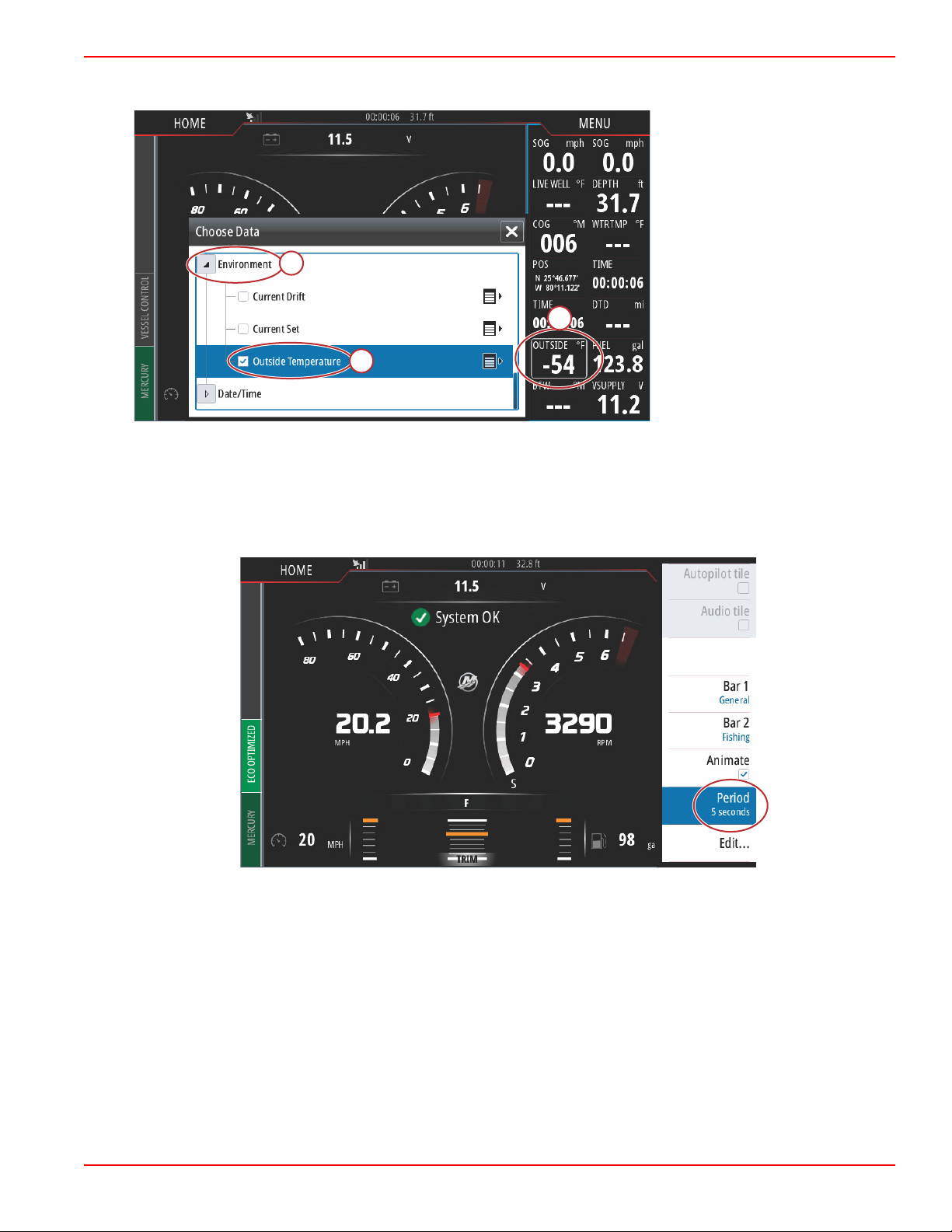
A select and drop‑down menu screen will appear. Select the entry that corresponds to the type of data that you wish to
populate the selected data tile in the Instrument bar.
a - Actively selected data tile
b - Entry and type of data to
replace actively selected data
tile
Use this procedure to complete the customization of the instrument bar.
When both instrument bars are active on the screen, the main display will appear smaller. To lessen the size of the instrument
bar, the operator can select the Animate option. This will return the instrument bar to one column of displayed data while
cycling between the two operator defined Bar 1 and Bar 2 selections. When the Animate option is selected, a keypad window
will appear. An Animation period duration can be set for up to 10 seconds between data cycling. Use the keypad to enter a
preferred duration in seconds. When finished entering a value on the keypad, select OK to return to the main screen.
90-8M0109374 eng JUNE 2016 Page 51
Page 57

Section 2 - Initial Screens and Setup Wizard
61737
Page 52 90-8M0109374 eng JUNE 2016
Page 58

Section 3 - Autopilot Features and Operation
Table of Contents
Section 3 - Autopilot Features and Operation
Economy Mode..................................................................... 54
ECO............................................................................... 54
Smart Tow Mode.................................................................. 57
Smart Tow..................................................................... 57
Features ................................................................ 58
Disabling Smart Tow ............................................. 61
Cruise Control Mode............................................................. 61
Cruise Control................................................................ 61
Activating Cruise Control Mode ............................. 62
Troll Control Mode................................................................ 64
Troll Control................................................................... 64
3
90-8M0109374 eng JUNE 2016 Page 53
Page 59

Section 3 - Autopilot Features and Operation
61749
Economy Mode
ECO
ECO mode displays information to guide the operator in setting the optimum trim position and engine speed to achieve the best
fuel economy. The engine control module (ECM) or propulsion control module (PCM) calculates the best fuel economy based
on information from various sensors on the power package and vessel.
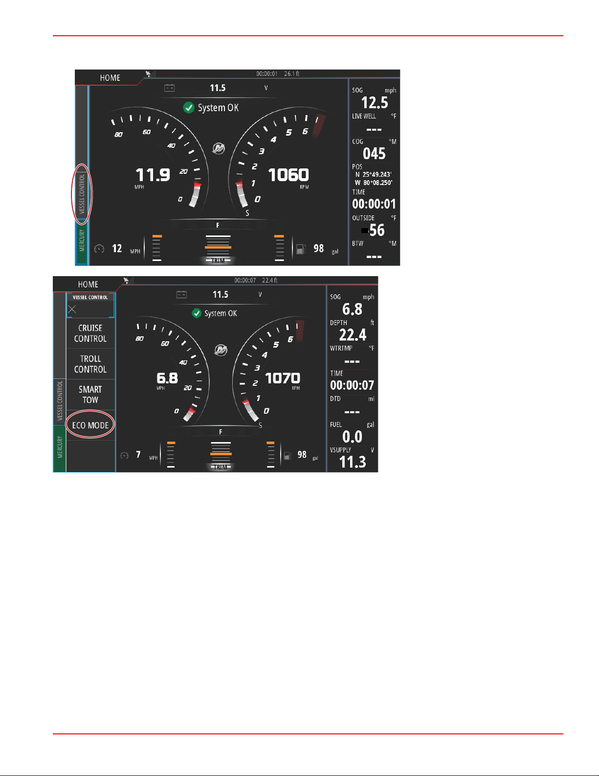
ECO mode is continually running. The ECO parameters are evaluated at all times during engine operation and the operator will
see the Vessel Control tab on the left‑hand side of the screen turn green and read ECO Optimized if the engine RPMs and trim
position happen to be in the proper ranges.
Page 54 90-8M0109374 eng JUNE 2016
Page 60
Section 3 - Autopilot Features and Operation
61750
61751
To actively monitor the ECO function of the VesselView, select the Vessel Control tab on the left‑hand side of the screen. This
will open the autopilot functions bar. Select the ECO MODE option.
90-8M0109374 eng JUNE 2016 Page 55
Page 61

Section 3 - Autopilot Features and Operation
61752
61753
In the ECO Mode panel, VesselView shows the operator the RPM value and the trim position. If one or both of these operating
parameters is out of optimization, the VesselView will display an orange arrow and/or orange sliders in the RPM and trim tiles.
The direction of the orange arrows indicates where to adjust the RPMs and trim position to achieve fuel economy optimization.
Following the guidance of the VesselView will result in both RPMs and trim position being optimized. When optimized, the
Vessel Control tab will display Eco Optimized in green, the trim slider will turn green, and a green leaf icon with the word
Optimized will appear at the top of the Eco Mode bar.
Page 56 90-8M0109374 eng JUNE 2016
Page 62

Section 3 - Autopilot Features and Operation
61754
61755
To minimize the ECO Mode bar, select the arrow icon in the upper left‑hand corner of the bar. This will bring the Vessel Control
bar to the main tiles. Select the X at the top left‑hand corner of the bar, or swipe the Vessel Control bar to the left to close it.
Smart Tow Mode
Smart Tow
Smart Tow is an easy to use program to manage boat acceleration and target speed goals for pulling skiers, tubers, or
watersport equipment of all varieties. Smart Tow takes the guesswork out of acceleration problems like too much hole shot, too
much overshoot, deceleration, and constant speed targets. Select a profile, select enable, and place the control handle to
wide‑open throttle, Smart Tow will do the rest.
90-8M0109374 eng JUNE 2016 Page 57
Page 63

Section 3 - Autopilot Features and Operation
61785
61786
a
The Smart Tow screen allows you to select, set, and modify settings in the Smart Tow features. The launch graph dot is
animated when Smart Tow is active and performing a launch sequence. The dot will move along the launch path showing what
part of the launch sequence the system is performing.
Smart Tow is based on the engine RPM unless the vessel has a GPS installed and connected to the control area network.
When the vessel contains a GPS, you can select either speed targets or engine RPM targets for Smart Tow control options.
You can also create custom launch profiles.
Features
Smart Tow utilizes the user‑selected data area and the footer section to allow you to adjust the settings. Touch or swipe to
move through the selection box fields. The footer section allows you to enable or disable Smart Tow, save, or exit. The items
located in the data area footer require the selection to be touched or use the rotary knob to highlight and select.
Smart Tow offers five factory preset launch profiles, or the operator can create new custom launch profiles. Custom profiles are
helpful when there are people onboard with varying levels of experience with watersports equipment. The operator can create
more aggressive launches for experienced skiers, as well as milder launches for children or inflatables towing.
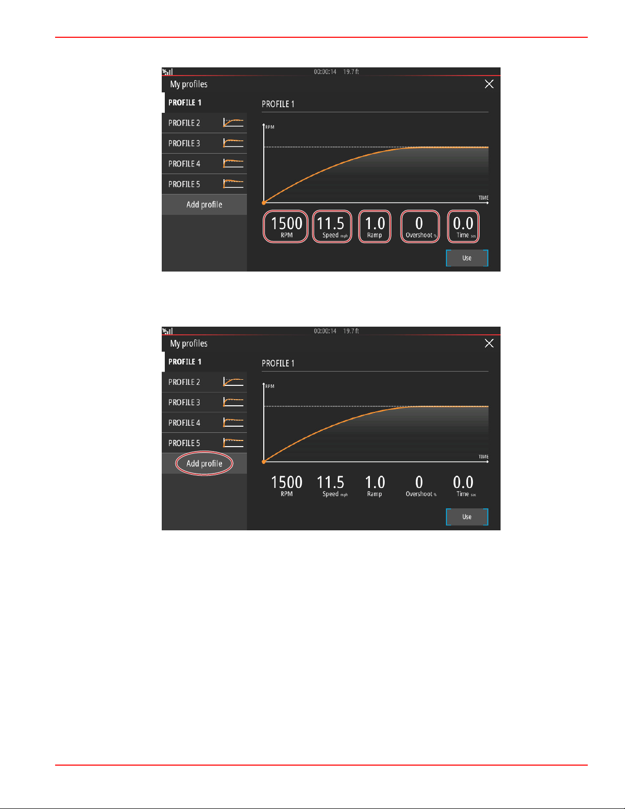
There are five selection fields within a profile. Use the rotary knob or touch to change the profile selections.
• RPM and speed. The operator can adjust the RPM or speed by selecting the data screen area.
• Ramp is the time that the boat will take to get to the set point.
• Overshoot is the percentage over the set point the boat will achieve.
Page 58 90-8M0109374 eng JUNE 2016
Page 64
Section 3 - Autopilot Features and Operation
61787
61788
• Time is the length of time that the boat will remain above the selected speed.
Five selection fields to create a profile
To create a new profile, select Add profile.
90-8M0109374 eng JUNE 2016 Page 59
Page 65

Section 3 - Autopilot Features and Operation
61789
61790
Using the on‑screen keyboard, give the new launch profile a name.
In the New Profile screen, the operator can edit each of the five selection fields. After all of the selections have been edited,
select the Use button to utilize the new Smart Tow launch profile.
Page 60 90-8M0109374 eng JUNE 2016
Page 66
Section 3 - Autopilot Features and Operation
61791
61792
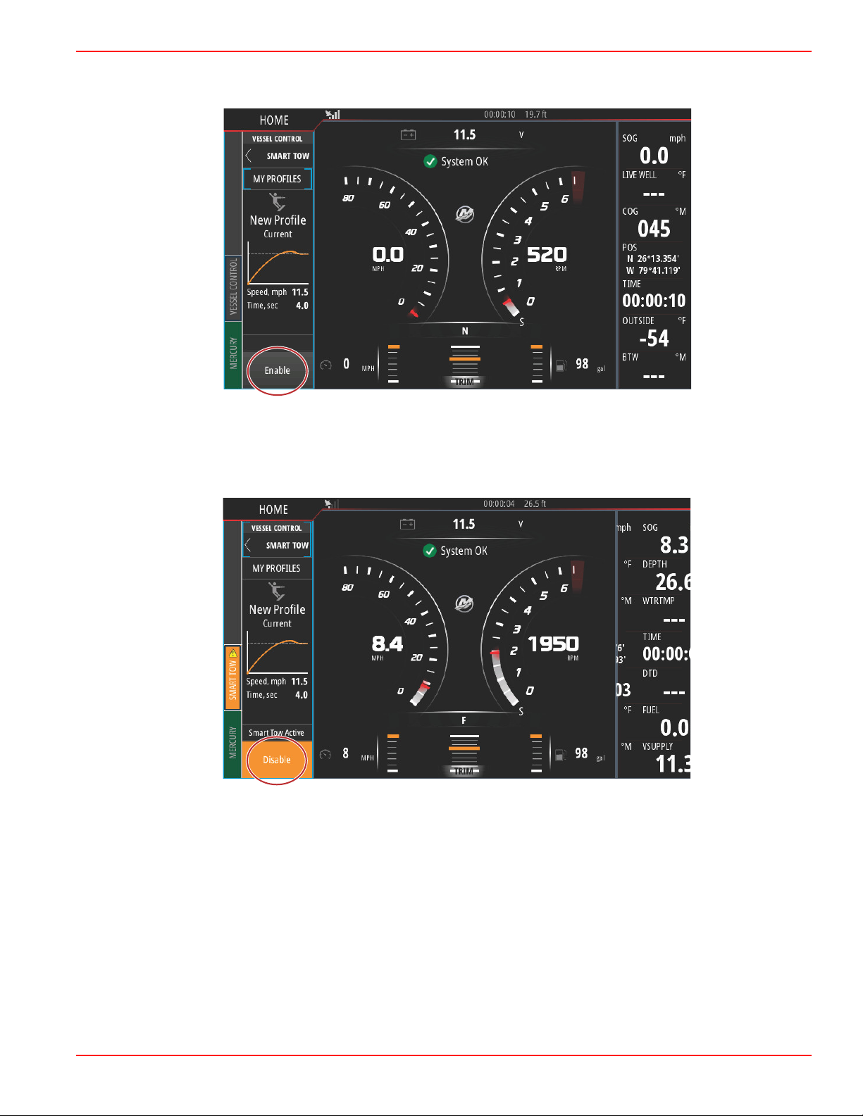
To activate any Smart Tow launch profile. Select the Enable option and place the throttle levers in wide‑open forward. Smart
Tow will take care of the rest.
Disabling Smart Tow
To exit out of Smart Tow, Disable must be selected. VesselView will transfer throttle control back to the operator. When Smart
Tow is enabled, moving the throttle lever to any point below the speed target will decrease the speed of the boat, but the top
speed of the boat will not increase beyond the target speed.
Cruise Control Mode
Cruise Control
The cruise feature allows the operator to select a set point and adjust the value so the vessel maintains a specific speed or
engine RPM.
• Cruise is RPM based, unless the vessel incorporates a Mercury Marine GPS into the control area network.
• If the vessel has a Mercury Marine GPS, the default setting is vessel speed.
• The operator can select either RPM set points or speed‑based set points. The type of cruise option can be changed in the
Settings menu.
NOTE: Cruise Control can be disabled by placing the remote control levers in neutral.
90-8M0109374 eng JUNE 2016 Page 61
Page 67
Section 3 - Autopilot Features and Operation
61767
61768
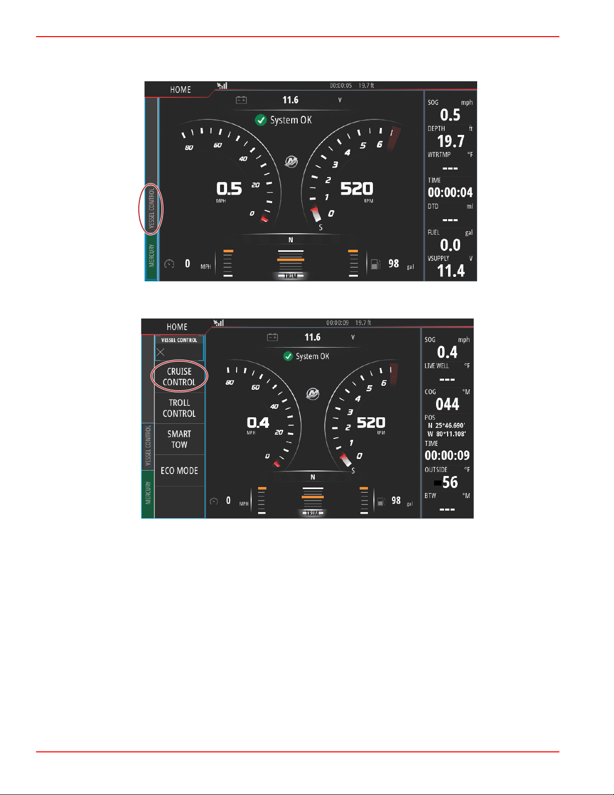
Activating Cruise Control Mode
To activate the Cruise autopilot option, select the Vessel Control tab on the left‑hand side of the screen.
Select the Cruise Control tile in the Vessel Control bar.
Page 62 90-8M0109374 eng JUNE 2016
Page 68

Section 3 - Autopilot Features and Operation
61769
61770
Select the up or down arrows to achieve the desired speed.
With the desired cruise speed set, select the Enable tile in the cruise bar. Place the remote control handles in the forward gear
position, and place the handles in the wide‑open throttle position. VesselView will increase the speed of the vessel to the
selected set point chosen by the operator.
90-8M0109374 eng JUNE 2016 Page 63
Page 69

Section 3 - Autopilot Features and Operation
61771
61757
When Cruise is active the Vessel Control tab will be orange, alerting the operator that the vessel is in an autopilot control mode.
Cruise Control mode can be cancelled by placing the remote control handles in the neutral position or by selecting the Disable
tile in the bottom of the Cruise Control bar. To access the Disable tile, select the Vessel Control tab on the left‑hand side of the
screen, this will bring up the Cruise Control bar and the Disable option.
Troll Control Mode
Troll Control
Troll RPM ranges are power package dependant, but the maximum RPMs for all engines or outboards is 1000 RPM.
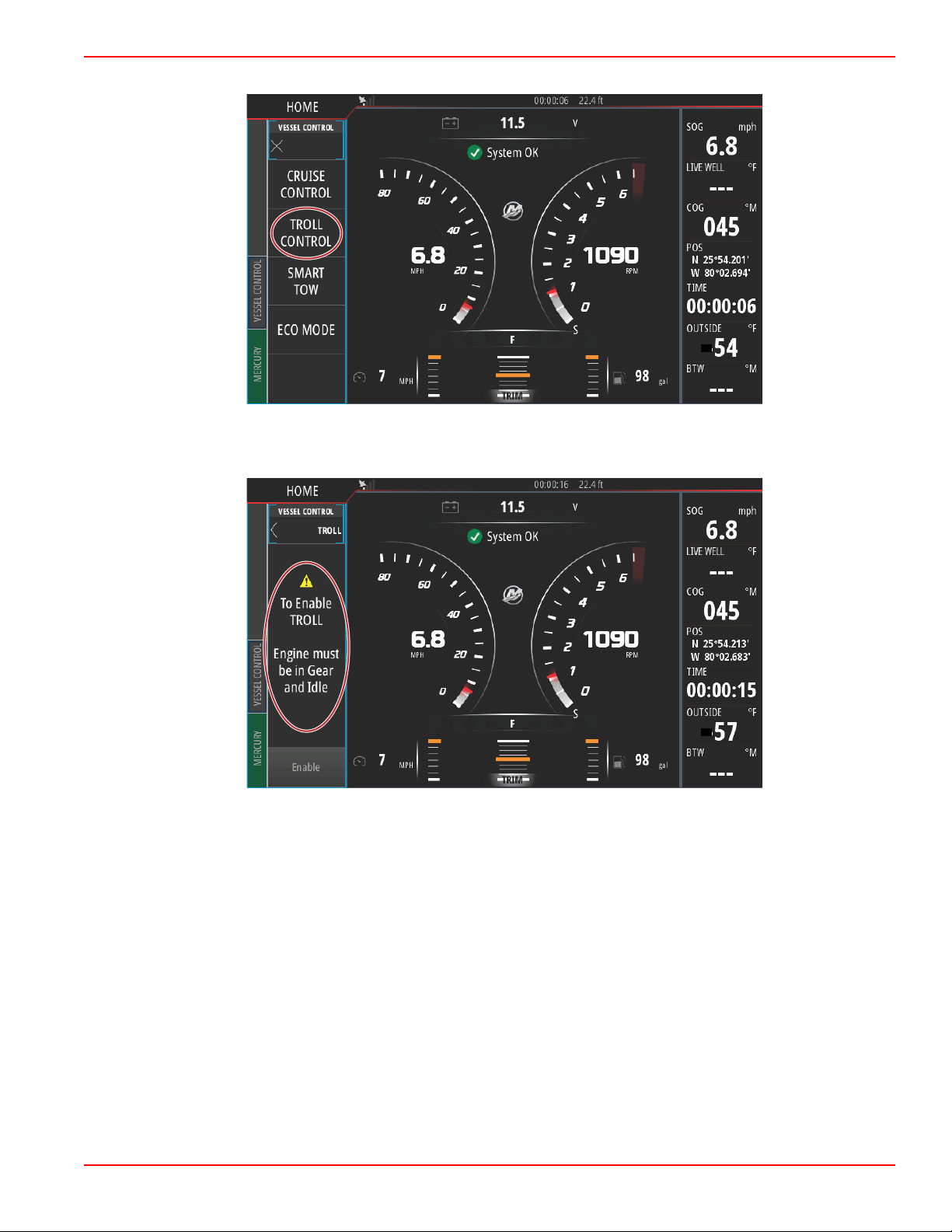
To activate Troll Control, select the Vessel Control tab on the left‑hand side of the screen.
Page 64 90-8M0109374 eng JUNE 2016
Page 70
Section 3 - Autopilot Features and Operation
61758
61759
Select the Troll Control tile in the Vessel Control Bar.
The vessel must be in gear and the throttle must be at idle. If the vessel does not meet these conditions, a warning icon and
accompanying text will instruct the operator on how to make Troll Control available.
90-8M0109374 eng JUNE 2016 Page 65
Page 71
Section 3 - Autopilot Features and Operation
61760
61761
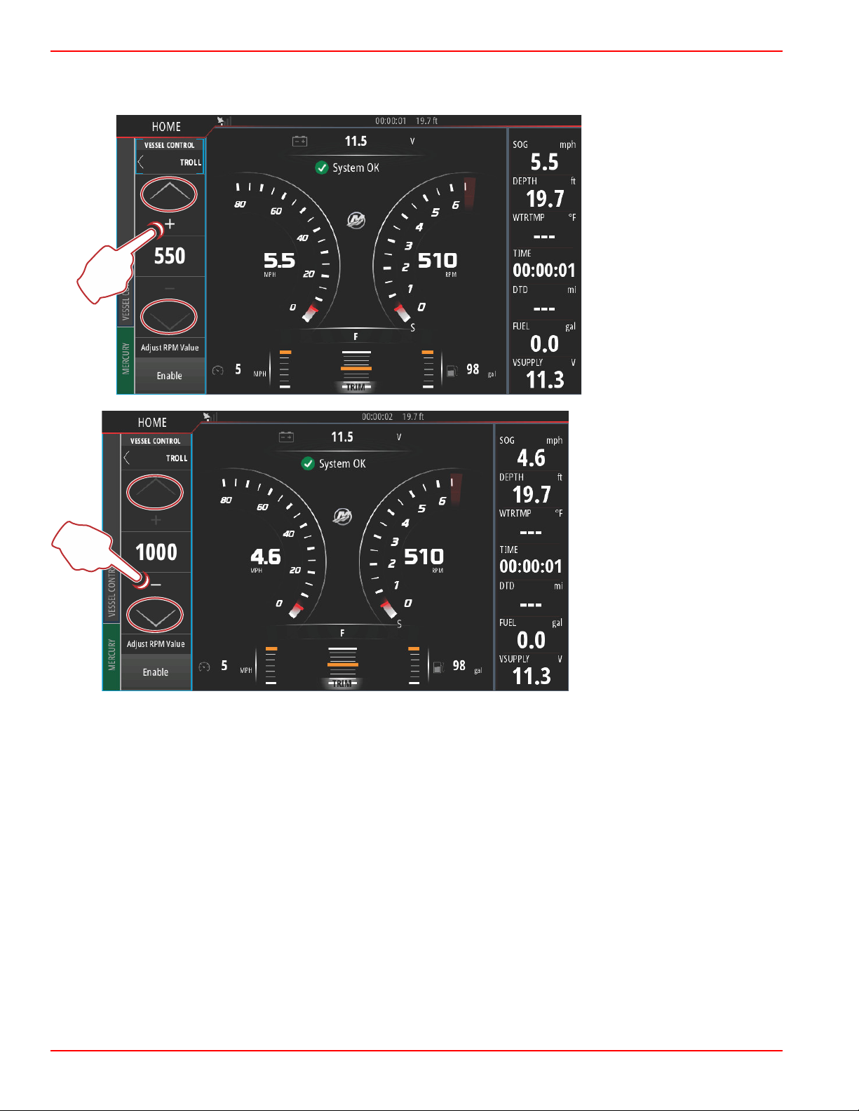
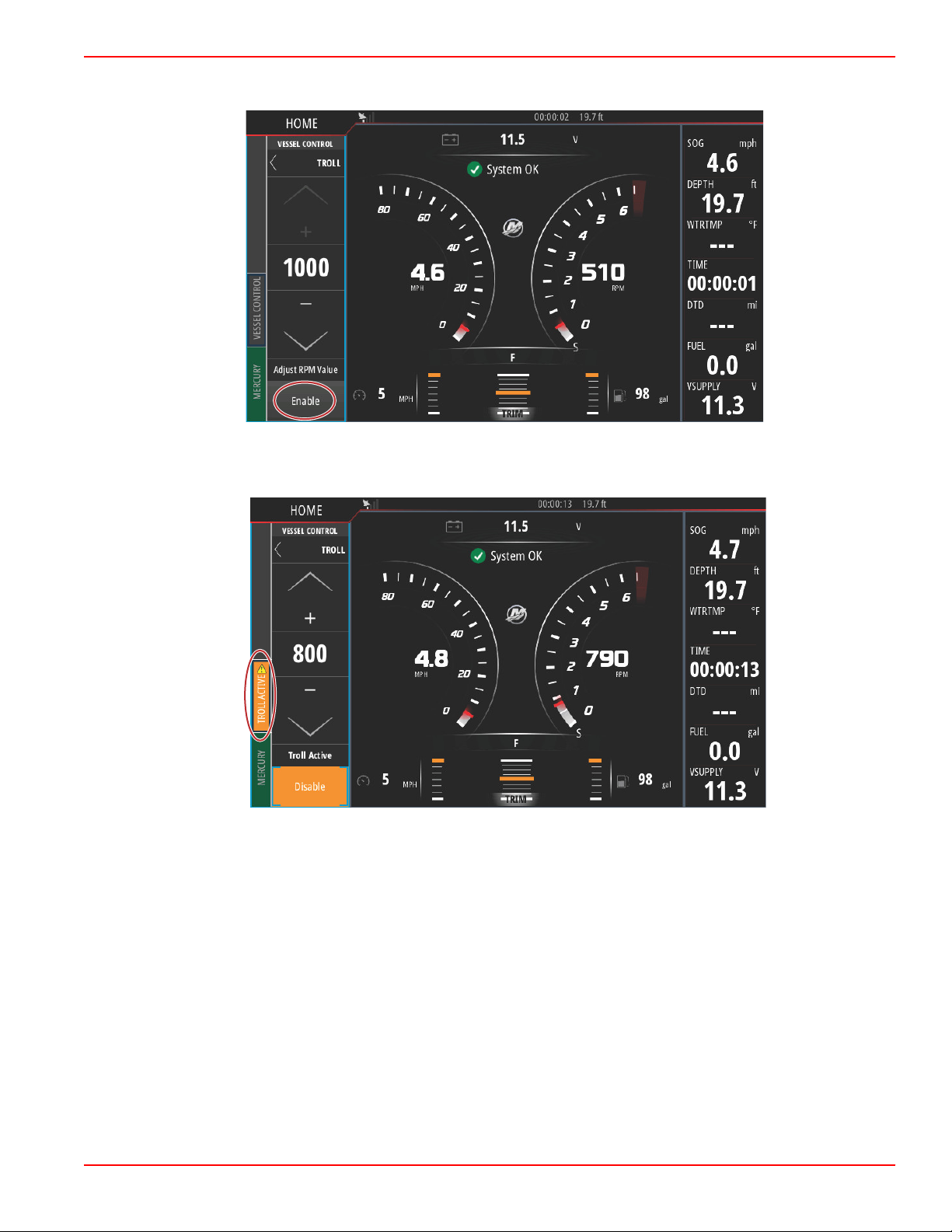
When gear and throttle conditions are met, the Vessel Control bar will display Troll Control options. The increase and decrease
arrows are grayed out when either the minimum or maximum RPM value has been selected. Select the + or – icons on the
screen to adjust the RPM value.
Page 66 90-8M0109374 eng JUNE 2016
Page 72
Section 3 - Autopilot Features and Operation
61762
61763
When the desired RPM value has been chosen, select the Enable tile. This will start Troll Control and the engines will climb to
the desired RPM.
The Enable tile will turn orange and read Disable. The Vessel Control tab will turn orange and display a warning symbol and the
text Troll Active.
90-8M0109374 eng JUNE 2016 Page 67
Page 73

Section 3 - Autopilot Features and Operation
61764
61765
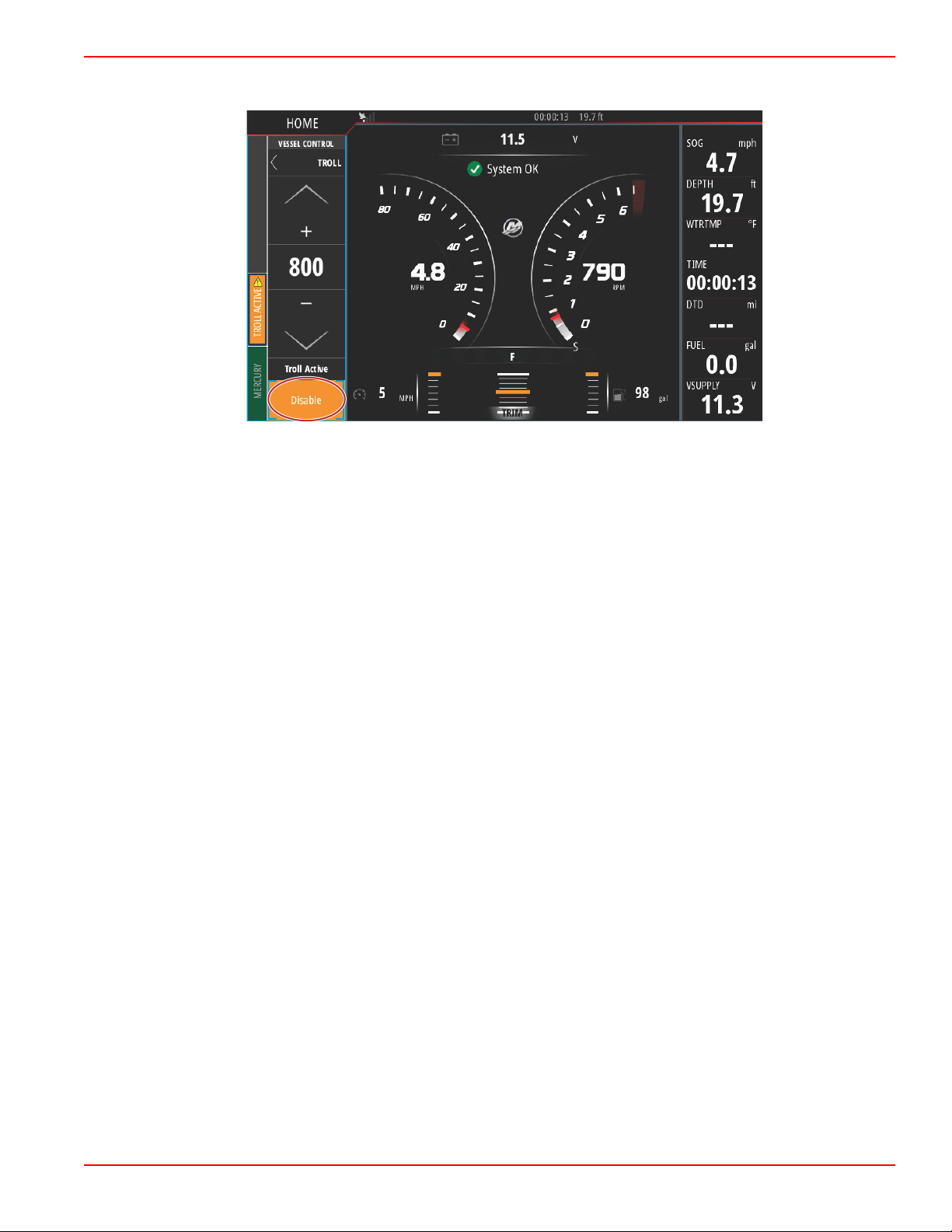
The Vessel Control bar can be minimized during Troll Control operation without affecting the Troll Control autopilot function.
Select the arrow in the upper left‑hand corner of the Vessel Control bar to minimize the bar.
The main screen returns to normal size and the Troll Active tab is visible in orange on the left‑hand side of the screen.
Page 68 90-8M0109374 eng JUNE 2016
Page 74
Section 3 - Autopilot Features and Operation
61766
To disable troll control, select the Troll Active tab, which will display the Troll Control options bar. Select Disable to turn Troll
Control off.
90-8M0109374 eng JUNE 2016 Page 69
Page 75

Section 3 - Autopilot Features and Operation
Notes:
Page 70 90-8M0109374 eng JUNE 2016
Page 76

Section 4 - Setup and Calibrations
Table of Contents
Section 4 - Setup and Calibrations
System Settings.................................................................... 72
Navigation to the Settings Menu.................................... 72
Helm and Device Locations........................................... 72
Setup Wizard................................................................. 73
Simulate......................................................................... 73
Vessel Settings..................................................................... 73
Tabs............................................................................... 73
Tanks............................................................................. 76
Speed............................................................................ 77
Steering......................................................................... 81
Vessel Control............................................................... 82
Cameras installed.......................................................... 83
Genset Enabled............................................................. 84
Maintenance Notification............................................... 84
Sea Temp...................................................................... 85
Engines Settings................................................................... 85
Engines Shown.............................................................. 85
Engine Model................................................................. 86
Limits............................................................................. 87
Supported Data..............................................................88
ECO Mode..................................................................... 89
Cruise/Smart Tow Type................................................. 90
Trim................................................................................90
Alarms.................................................................................. 91
Alarms Setting............................................................... 91
Personality File..................................................................... 92
Export............................................................................ 92
Import.............................................................................93
4
90-8M0109374 eng JUNE 2016 Page 71
Page 77

Section 4 - Setup and Calibrations
61655
61656
System Settings
Navigation to the Settings Menu
Changes in any of the settings can be made at any time using the Settings menu. All drop‑down and flyout menus can be
navigated by touching the screen or by using the rotary knob.
The Settings menu can be found by swiping downward from off the screen onto the upper portion of the screen. This will bring
up the System Controls window. Select the Settings tile. A menu will appear on the left portion of the screen. Select Mercury
from the list of options. The window of VesselView settings controlled by the Mercury side of the MFD will appear.
Helm and Device Locations
Within the System Settings the operator can define the location and the number of the VesselView device. This is important
when there are multiple VesselViews installed on a vessel. Assigning unique helm locations and device numbers prevents
communication errors over the control network.
Page 72 90-8M0109374 eng JUNE 2016
Page 78

Section 4 - Setup and Calibrations
61657
61658
Setup Wizard
Setup wizard is covered in Section 2. Changes to the Setup wizard can be made at any time by accessing the program through
this menu.
Simulate
Simulate is used at a dealer level, to show consumers the display characteristics of the display. When the unit is in Simulate
mode, the data shown on the screen should not be used as navigation information. All data shown during Simulate is randomly
generated.
Vessel Settings
Tabs
The Settings menu can be found by swiping downward from off the screen onto the upper portion of the screen. This will bring
up the System Controls window. Select the Settings tile. A menu will appear on the left portion of the screen. Select Mercury
from the list of options. The window of VesselView settings controlled by the Mercury side of the MFD will appear.
90-8M0109374 eng JUNE 2016 Page 73
Page 79

Section 4 - Setup and Calibrations
61659
61660
Select the Vessel settings option.
Select the Tabs option.
Tabs settings allows the operator to display the tab positions on the screen by selecting the Show checkbox. The Source option
allows selecting the outboard or drive that carries the Tab sensor data to the network.
The tab sensor data is sent by one of the outboards or drives on the vessel. Use the following image to determine the proper
selection.
Page 74 90-8M0109374 eng JUNE 2016
Page 80

Section 4 - Setup and Calibrations
61661
aaa
bbb
c
c
d
60056
a
61669
abc
In addition to the PCM selections, there are options to select either the TAB—trim tab interface module, or the TVM—thrust
vector module, to send tab data to the VesselView.
Drive assignment options
a - PCM0 = starboard or starboard outer
b - PCM1 = port or port outer
c - PCM2 = starboard inner or center
d - PCM3 = port inner
Tab calibration allows the operator to put the tabs in their uppermost and lowermost positions and record the percentages. This
is useful for determining the true 0° trim position—the point at which the tabs are parallel with the bottom of the vessel.
Correctly calibrated tabs will show an accurate position of the sliders on the screen.
To calibrate the tabs, trim the tab parallel to the hull, record the reading, this will be the tabs actual 0%. Trim the tab all the way
down, record the reading, this will be the tabs actual 100%. Select Save to keep the new calibrated tab data.
a - Select the number of points of
calibration desired
b - Position of the tabs for
recording purposes
c - Select save to keep the
calibration
90-8M0109374 eng JUNE 2016 Page 75
Page 81

Section 4 - Setup and Calibrations
61662
61671
abc
The Set outboard or drive to Zero is the actual tab position that will read 0% on the display. Operators can determine at which
point the vessel runs flat in the water. At this running position, the tabs may actually be at a percentage of downward angle.
The Set to Zero option allows the operator to have the optimal flat aspect of the vessel read as 0% on the gauge. As an
example 10% actual tab position is where the boat runs flat, so the VesselView will display it as 0. Go below 10% and it will
show negative numbers.
Tanks
Tank configuration is covered in the Setup Wizard, but additional changes and settings can be made through the Tanks menu
at any time.
Tank settings and calibrations allow the selection of the type of tank, the capacity of the tank, and the calibration method for
tanks.
Performing Tank Calibration: There are many situations in which a tank may need calibration; odd shaped tanks, V‑bottomed
tanks, stepped‑sided tanks, and even a tank's aspect when the boat is in the water. Floats and senders can send inaccurate
data to the operator, causing problems with fuel and other volume display. The most accurate way to achieve tank calibration is
to start with an empty tank with a known capacity. Pump one quarter of the capacity and record the float or sender position.
Repeat this procedure in one quarter increments, recording the float or sensor position each time, until the tank is full. Tank
calibration allows the operator to adjust the full through empty readings of a tank. When a tank is highlighted, select the arrow
on the right side of the tab to activate the calibration screen. The default readings are in the second column, and can be
selected. In the following example, we know that the fuel tank is full, but we are receiving a reading of 79 percent full. Select the
record button in the 100 percent row, VesselView will now consider a reading of 79 percent as full, and adjust the half and
empty readings accordingly. When the level of a tank is known to the operator, tank calibration can be used to correct the
gauge reading to match the known level at any time.
a - Current full reading before
calibration
b - Record calibration fields
c - Save the current calibration
data
Page 76 90-8M0109374 eng JUNE 2016
Page 82

Section 4 - Setup and Calibrations
61684
61685
When tank calibration is complete, select Save and the unit will return to the navigation screen.
Speed
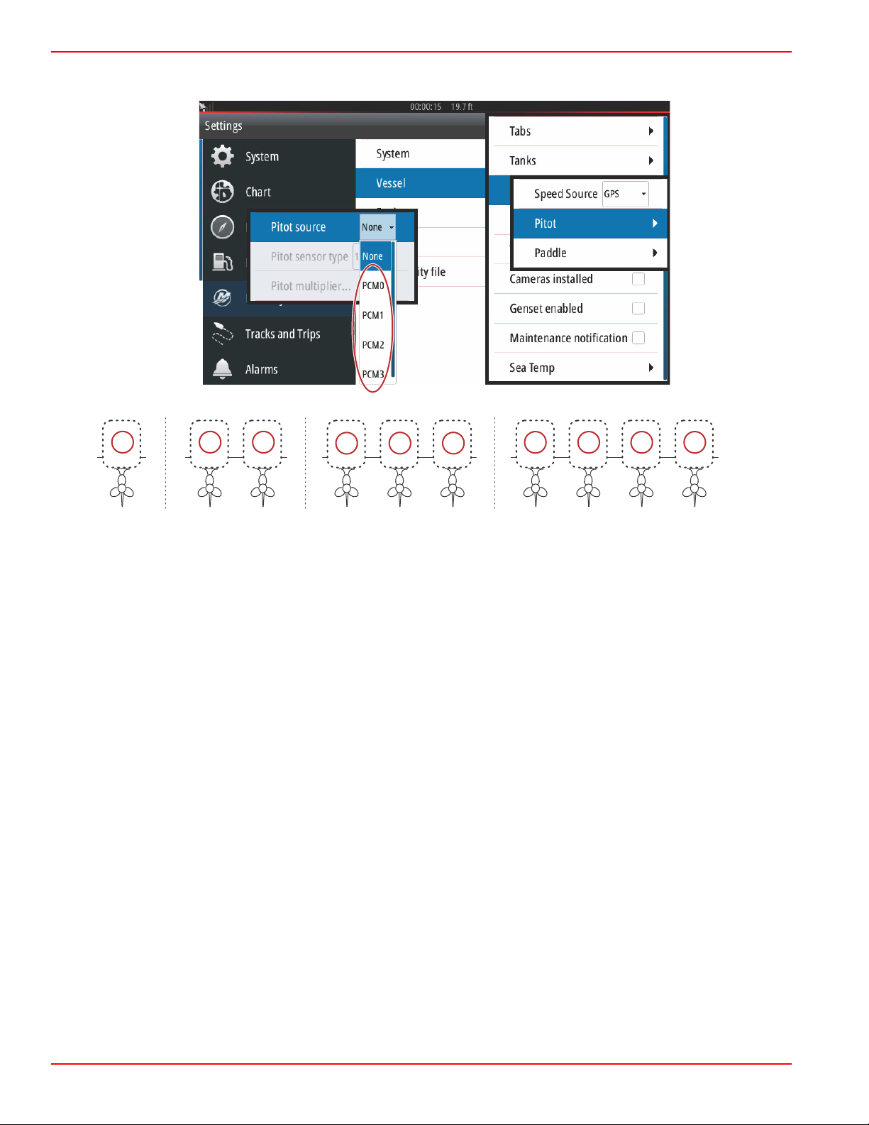
Speed settings allow the operator to select the type of sensor or sender that the VesselView will receive speed data from.
Speed settings can be configured using this menu.
Speed source has the option of choosing a GPS and the GPS source, the CAN P or the CAN H network. A strategy using a
pitot sensor and/or a paddle wheel can also be selected. Selecting the pitot or paddle wheel options brings up a selection of
sources.
90-8M0109374 eng JUNE 2016 Page 77
Page 83
Section 4 - Setup and Calibrations
61686
aaa
bbb
c
c
d
60056
a
The pitot sensor data is sent by one of the outboards or drives on the vessel. Use the following images to determine the proper
selection.
Drive assignment options
a - PCM0 = starboard or starboard outer
b - PCM1 = port or port outer
c - PCM2 = starboard inner or center
d - PCM3 = port inner
Pitot type options include 100 psi and 200 psi. The 200 psi option only applies to select Mercury Racing outboard models.
The pitot multiplier will use 1.00 as a default setting and can be increased or decreased to correct speed display readings that
read too high or too low. For a low speed reading, increase the pitot multiplier by selecting the multiplier window and use the
on‑screen keypad to enter an amount. For a high speed reading, decrease the pitot multiplier by selecting the multiplier window
and use the on‑screen keypad to enter an amount.
Page 78 90-8M0109374 eng JUNE 2016
Page 84

Section 4 - Setup and Calibrations
61687
aaa
bbb
c
c
d
60056
a
Select the outboard or drive that will send paddle wheel data to the VesselView. Use the following images to determine the
proper selection.
Drive assignment options
a - PCM0 = starboard or starboard outer
b - PCM1 = port or port outer
c - PCM2 = starboard inner or center
d - PCM3 = port inner
Paddle wheel type can be chosen as either Legacy or Current depending on the model used on the vessel.
90-8M0109374 eng JUNE 2016 Page 79
Page 85
Section 4 - Setup and Calibrations
61688
61689
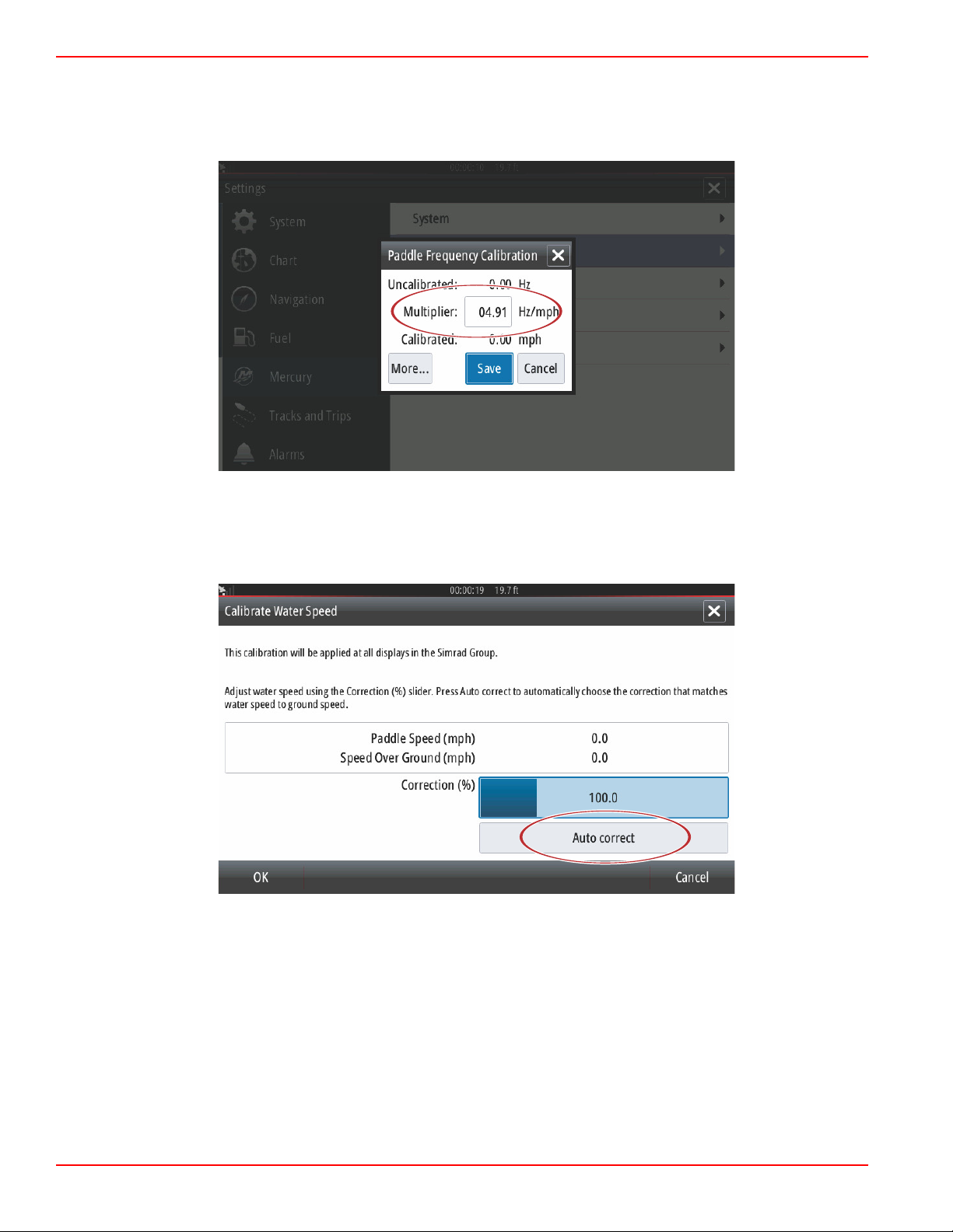
Paddle wheel frequency can be changed to match the requirements of different sensors. The frequency of the paddle wheel
speed sensor offered by Mercury Marine is 4.9 Hz per mile or 5.7 Hz per knot. Check the instructions that came with the paddle
wheel for specific information on the paddle wheel frequency output. Select the multiplier window and use the on‑screen
keypad to enter an amount. Selecting Auto correct will synchronize the paddle wheel to the output of the GPS. The slider bar
can also be used to achieve that same result.
Calibration of the paddle wheel is accomplished by using a GPS enabled device to help the operator adjust the reading of the
paddle wheel. Using the slider allows the operator to increase or decrease the paddle wheel sender data.
Selecting Auto correct will synchronize the paddle wheel to the output of the GPS (if installed on the network). The slider bar
can also be used to achieve that same result.
Page 80 90-8M0109374 eng JUNE 2016
Page 86
Section 4 - Setup and Calibrations
61697
61698
aaa
bbb
c
c
d
60056
a
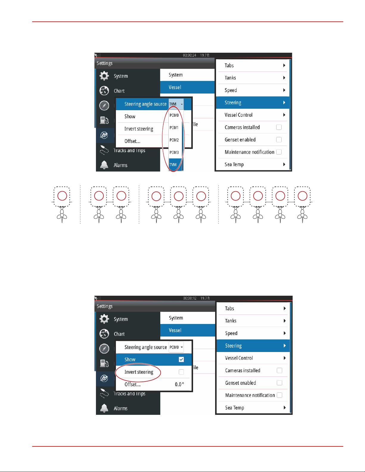
Steering
Steering source data can be selected to come from either the PCM or the TVM—thrust vector module, with options to display
the data on‑screen, to invert steering input, and to establish a steering offset degree.
Drive assignment options
a - PCM0 = starboard or starboard outer
b - PCM1 = port or port outer
c - PCM2 = starboard inner or center
d - PCM3 = port inner
The Invert steering option is helpful when there is a VesselView which is rear‑facing. In this case the steering data will match
the operator's point of view.
90-8M0109374 eng JUNE 2016 Page 81
Page 87

Section 4 - Setup and Calibrations
61699
61700
Steering Offset is used to align the outboard, sterndrive, or inboard to zero degrees. When the drive is positioned perpendicular
to the hull, the steering angle displayed on‑screen may not match the steering sensor on the drive. To adjust for this variance,
select the Offset window. The Steering Angle Calibration box appears. Selecting the Calibrated row Zero button will apply the
offset. Note that the offset does not change on the display screen until the Save button is selected.
Vessel Control
Vessel Control settings allows the operator to activate the availability of the autopilot features.
Page 82 90-8M0109374 eng JUNE 2016
Page 88

Section 4 - Setup and Calibrations
61709
61701
Selections for autopilot features are Cruise, Troll, Smart Tow, and Eco Mode. A Reset to defaults will uncheck any or all of the
autopilot features that are not available based on the power package of the vessel chosen in the Setup Wizard.
NOTE: If after the Reset to defaults option is chosen, all of the boxes are unchecked, your engine does not support the
autopilot features of the VesselView.
Cameras installed
Cameras installed allow the user to view videos or camera sources on the VesselView screen. VesselView supports two video
channels. You can select to view one channel only, or to cycle the screen between available video cameras. The cycle period
can be set from 5 to 120 seconds. The display can be optimized by adjusting the video settings. The adjustments are individual
to each source.
IMPORTANT: If the vessel does not have cameras installed, make sure that this option is unchecked. In certain situations, the
VesselView can experience disruptions in data display if the Cameras installed box is checked and the VesselView cannot
locate camera sources.
90-8M0109374 eng JUNE 2016 Page 83
Page 89
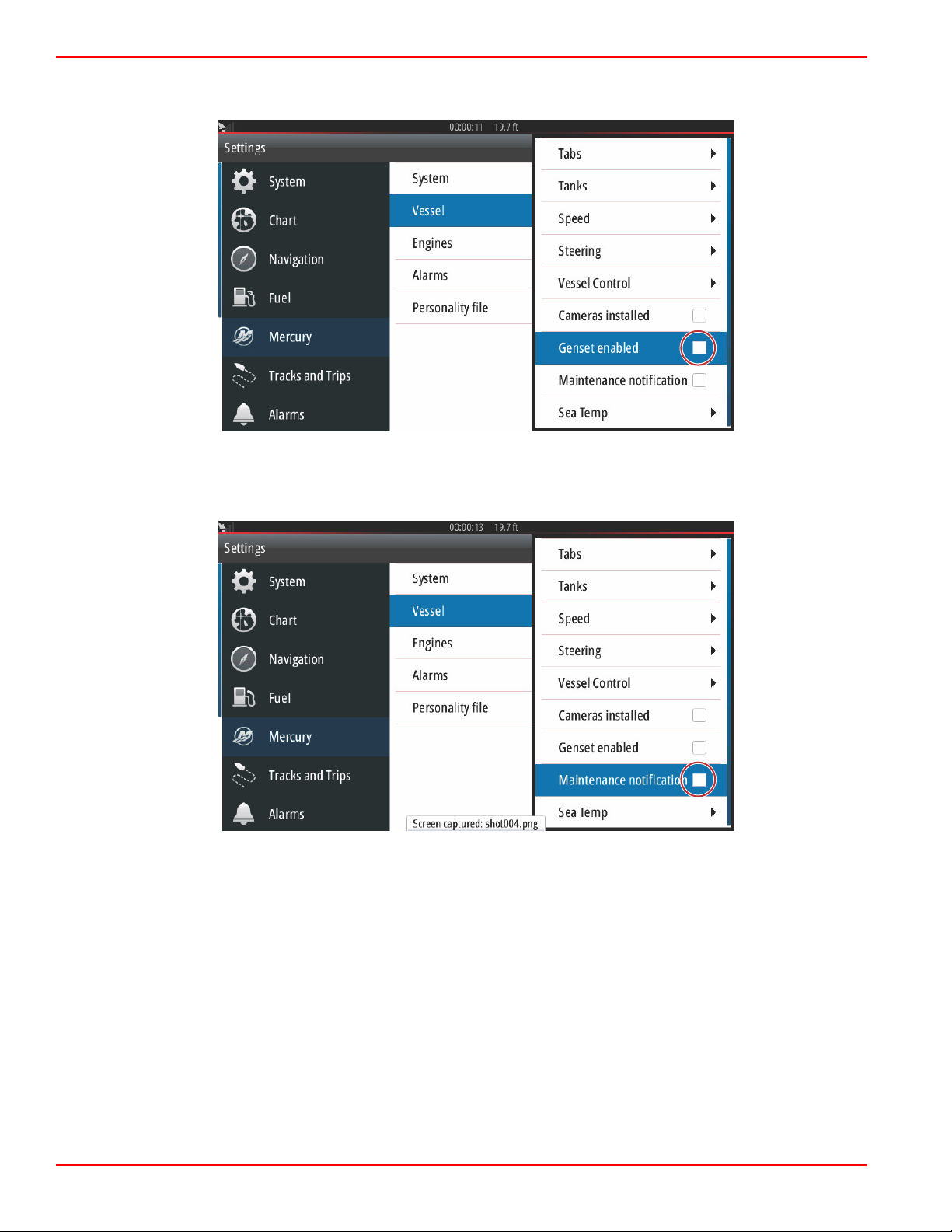
Section 4 - Setup and Calibrations
61702
61703
Genset Enabled
Genset enabled allows the VesselView to query the network for genset data.
Maintenance Notification
The Maintenance notification checkbox will allow VesselView to display scheduled maintenance pop‑ups on‑screen.
Page 84 90-8M0109374 eng JUNE 2016
Page 90

Section 4 - Setup and Calibrations
61704
aaa
bbb
c
c
d
60056
a
Sea Temp
The Sea Temperature Source can be selected by choosing the engine that will send the data or by selecting the appropriate
sensor from the list.
The following illustration shows the physical location of the PCMs.
PCM locations
a - PCM0 = starboard or starboard outer
b - PCM1 = port or port outer
c - PCM2 = starboard inner or center
d - PCM3 = port inner
Engines Settings
Engines Shown
The Settings menu can be found by swiping downward from off the screen onto the upper portion of the screen. This will bring
up the System Controls window. Select the Settings tile. A menu will appear on the left portion of the screen. Select Mercury
from the list of options. The window of VesselView settings controlled by the Mercury side of the MFD will appear.
90-8M0109374 eng JUNE 2016 Page 85
Page 91

Section 4 - Setup and Calibrations
61672
61673
Engines shown is covered during the Setup Wizard process, but display options can be changed in the Engines settings menu
at any time. VesselView can display up to four engines, depending on the number of engines chosen during the Setup Wizard
process. The operator can select which engines are displayed. Checking or unchecking the engine selection will determine
which engines are displayed on the VesselView.
Engine Model
Engine model selection allows the user to change power package descriptions. Engine models is covered during the Setup
Wizard, but changes can be made anytime. Any changes made here may make other settings and display options unavailable
in VesselView.
Page 86 90-8M0109374 eng JUNE 2016
Page 92
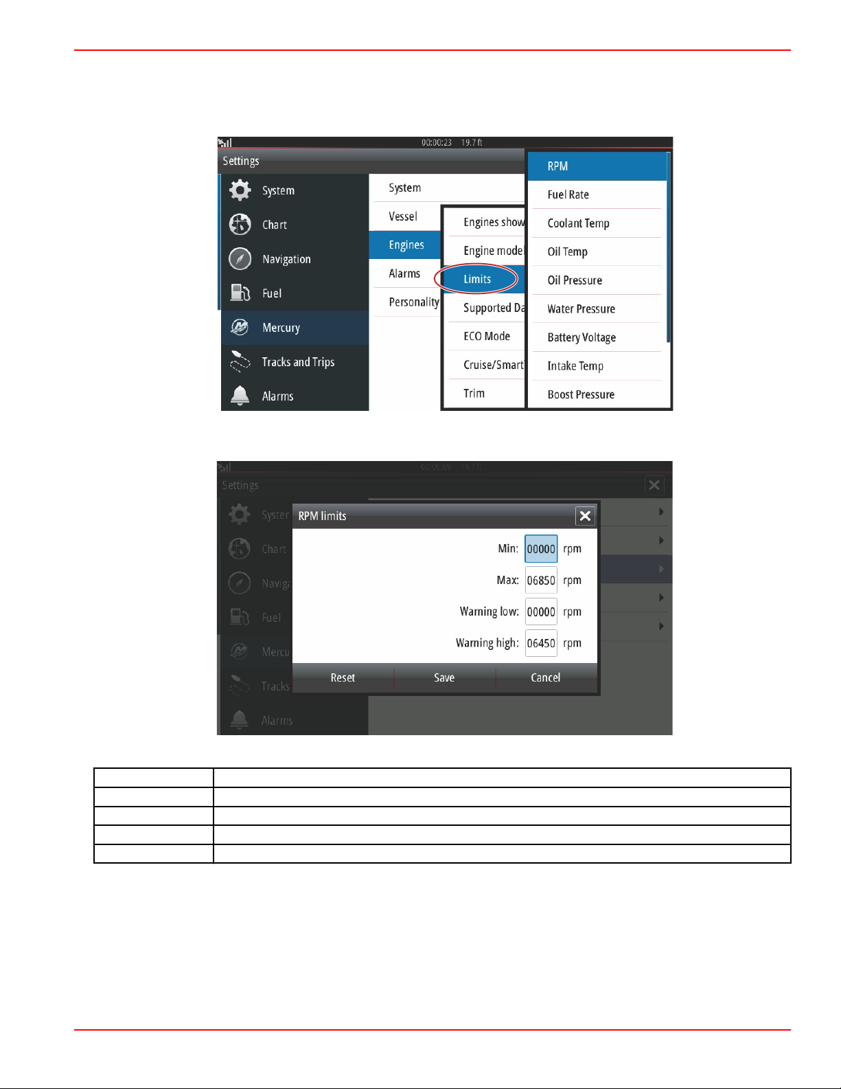
Section 4 - Setup and Calibrations
61674
61675
Limits
Limits helps set specific ranges for many engine data parameters, such as; RPM, coolant temperature, oil temperature, battery
voltage, and boost pressure. Changes made to limits will not affect the engine package or the operation of Mercury's Engine
Guardian programming. The actual engine limits are determined by the factory programmed control module on the engine.
The following image shows a typical Engine Limits screen.
Setting
Min: The value of the base of the on‑screen graph
Max: The value of the top of the on‑screen graph
Warning low: The value at the top of the lower color section of the on‑screen graph
Warning high: The value at the bottom of the upper color section of the on‑screen graph
Description
The default minimums and maximums are factory preset to the engine package chosen during the Setup Wizard or the Engines
Setting menu. Increasing or decreasing the warning minimums and maximums is generally regarded as the boater's personal
preference.
NOTE: If the operator is utilizing the Navico side of the MFD, and any min/max warning limits in the Mercury side are exceeded,
there will be an alert beep generated.
90-8M0109374 eng JUNE 2016 Page 87
Page 93

Section 4 - Setup and Calibrations
61705
61706
Supported Data
Supported Data allows the operator to select the types of data that the VesselView will display. The list of data sources is
dependent on the power package selected during the Setup Wizard. Select the checkbox for each data item you want
VesselView to be able to display.
Selected data items shown circled
Page 88 90-8M0109374 eng JUNE 2016
Page 94

Section 4 - Setup and Calibrations
61707
61711
ECO Mode
The ECO Mode menu option shows the current operating parameters to keep the engine optimized for the best fuel efficiency.
The operator can check these ECO parameters without being in the ECO Mode. Selecting Refresh will evaluate engine data
and adjust the RPM recommendations as needed.
90-8M0109374 eng JUNE 2016 Page 89
Page 95

Section 4 - Setup and Calibrations
61712
61715
Cruise/Smart Tow Type
The Cruise/Smart Tow type setting allows the operator to select the sensor from which the Cruise autopilot program and the
Smart Tow program launch profiles get their speed data. Engine RPM or GPS speed data are the options. Selecting Auto will
make VesselView query the network for a source of speed based data and use that selection for the Cruise and Smart Tow
features.
Trim
Trim settings allow the operator to enable the Show checkbox, to display the trim status graphic on the screen. The Has Trim
checkbox must be checked in order for the ECO Mode to give guidance to the operator as to the proper trim position for
achieving the best fuel economy.
Trim calibration allows the operator to position the trim to the innermost and outermost positions and record the percentages.
This is useful for determining the true 0° trim position—the point at which the trim is parallel with the bottom of the vessel.
Correctly calibrated trim will show an accurate position of the sliders on the screen.
Page 90 90-8M0109374 eng JUNE 2016
Page 96
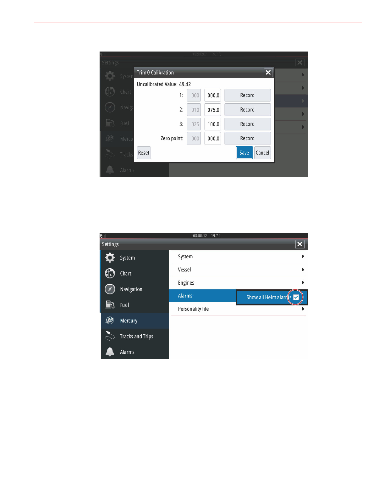
Section 4 - Setup and Calibrations
61716
61718
To calibrate the trim, trim the engines all the way in and record the reading—row 1, this will be the trim actual 0%. Trim the
engines all the way out, record the reading—row 3, this will be the trim actual 100%. The Zero point is when the engines are
positioned parallel with the bottom of the vessel, record that position. Select Save to keep the new trim calibrated data.
Alarms
Alarms Setting
The Show all Helm alarms option can be checked to display all alarms on all VesselView screens. Unchecking the option will
result in loss of notifications on additional VesselViews involving multiple device installations.
90-8M0109374 eng JUNE 2016 Page 91
Page 97
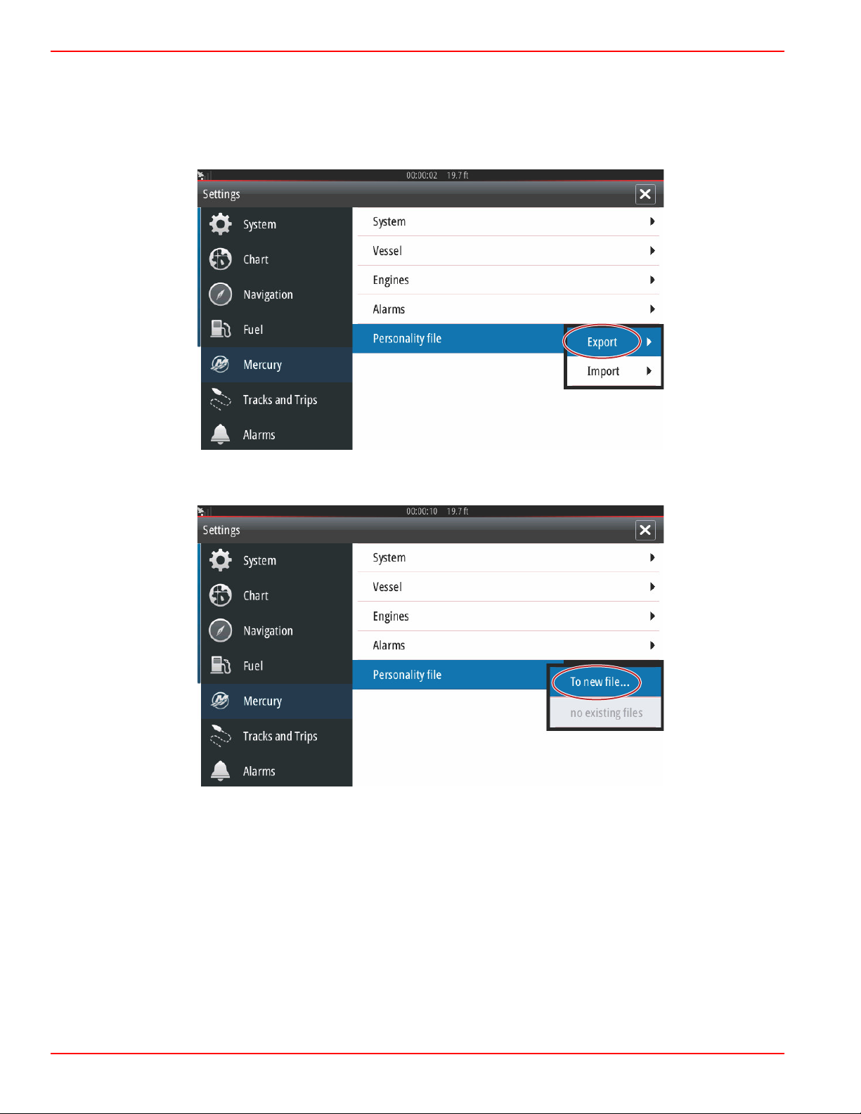
Section 4 - Setup and Calibrations
61719
61720
Personality File
Export
A vessel Personality file is made up of all of the settings that have been made within a VesselView device. To export this
personality, insert a SD card into the card port slot and select Export. Remove the SD card and transfer that file to another
VesselView device using the Import option.
Select Export
Select To new file...
Page 92 90-8M0109374 eng JUNE 2016
Page 98

Section 4 - Setup and Calibrations
61721
61722
Select Yes
The new Personality file will be written to the top level of the memory card. It will not be placed inside any folders on the SD
card.
Import
To Import a Personality file, insert an SD card into the card port that has a VesselView written Personality file stored on it.
Select Import. A list of detected files will appear on the screen. Select the file and begin the import.
Personality file
90-8M0109374 eng JUNE 2016 Page 93
Page 99

Section 4 - Setup and Calibrations
61723
You will be prompted one more time to replace all existing settings. Select Yes. The VesselView will import the new Personality
file and the unit will restart.
Page 94 90-8M0109374 eng JUNE 2016
Page 100

Section 5 - Warning Alarms
Section 5 - Warning Alarms
Table of Contents
Warnings—Faults and Alarms.............................................. 96 Shallow Water and Low Fuel Alarms .................... 98
5
90-8M0109374 eng JUNE 2016 Page 95
 Loading...