

Page 1
VESSELVIEW 903
63125
IMPORTANT: This document guides our dealers, boatbuilders, and company service personnel in the proper installation or
service of our products. If you have not been trained in the recommended servicing or installation procedures for these or
similar Mercury Marine products, have the work performed by an authorized Mercury Marine dealer technician. Improper
installation or servicing of the Mercury product could result in damage to the product or personal injury to those installing or
operating the product. Always refer to the appropriate Mercury Marine service manual for component removal and installation
instructions.
NOTE:
After completing installation, place these instructions with the product for the owner's future use.
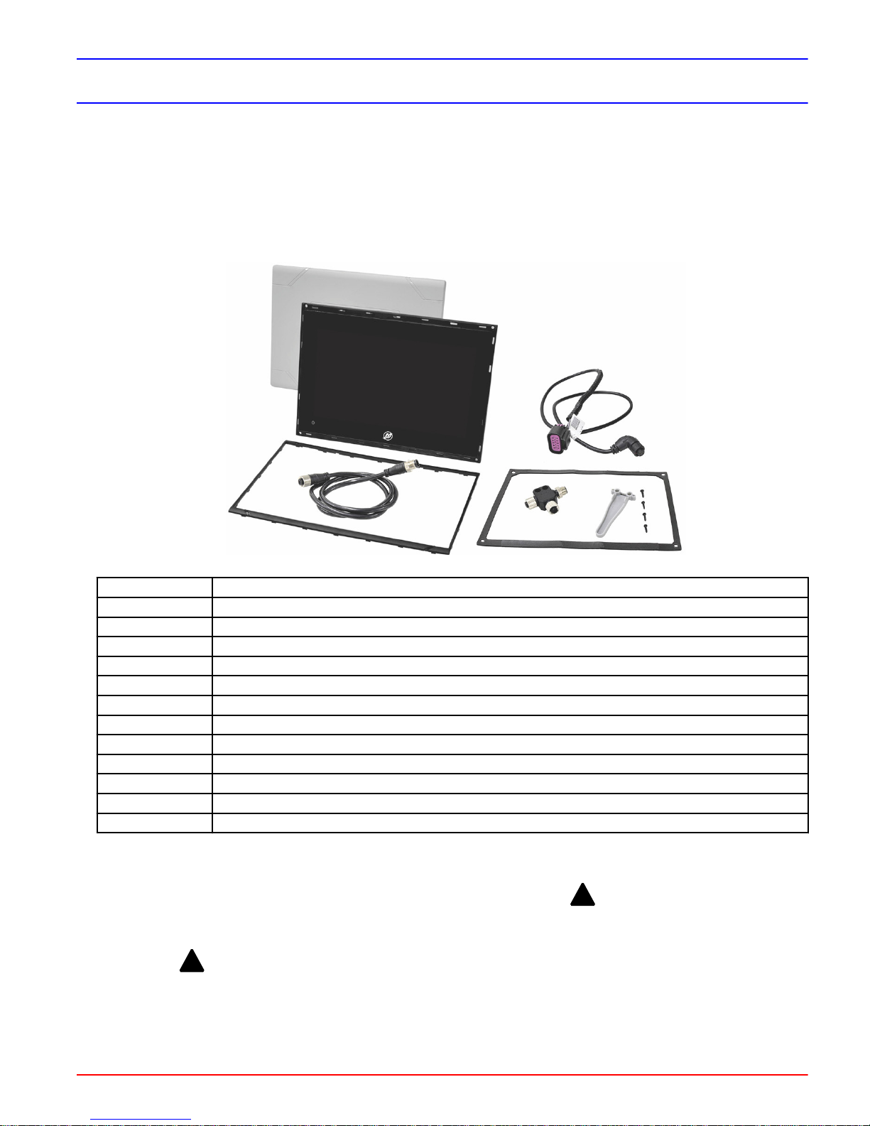
Components Contained in Kit
Qty. Description
1 VesselView multifunction display
1 Sealing gasket
4 Mounting screws—#4 supplied
1 Mounting screw alignment tool
1 NMEA® 2000 T‑connector
1 VesselView power harness
1 NMEA 2000 extension harness
1 Bezel
1 Sun cover
1 Template
1 Quick Start guide
1 Operation manual
Notice to Installer
IMPORTANT: The documentation must be consulted in all cases where the symbol !, is marked.
Safety Requirements
IMPORTANT: !Always refer to the Operation Manual included with each engine for other important safety information.
Water depth may vary in identical locations at different times of the day or year. As operator, always monitor water depth.
Reduce speed and proceed with caution whenever you're driving a boat in shallow water or in areas where the waters are
suspected of having underwater obstacles that could be struck by the underwater drive components, or the boat bottom. Do
not use mobile devices as the sole source of navigation, or engine and vessel data.
90-8M0129930 eng MAY 2017 © 2017 Mercury Marine Page 1 / 5
Page 2
VESSELVIEW 903
WARNING
!
Rotating propellers and pinch points can cause serious injury or death. Stay clear of the sterndrive or outboard engine
when the engine is running.
WARNING
!
This unit has not been assessed as a safety component and is not to be relied upon as a safety device.
Specifications
IMPORTANT: !Always refer to the Operation Manual included with each engine for fuse holder location, fuse rating, and
electrical system overload protection.
This equipment is only intended for connection to 9–16 Vdc, low voltage, electrical systems of boats or similar marine vessels.
Do not connect this equipment to any circuit rated in excess of 16 Vac rms, 22.6 Vpk or 35 Vdc, and only connect to boat
electrical systems powered by batteries or alternators or otherwise only to circuits separated from main voltages by at least
double or reinforced insulation.
This product must not be installed in a manner inconsistent with the recommended procedures set forth in the installation
instructions included with the product. Improper installation or removal of the product can cause injury, or damage to the
vessel or engine components.
Cutting the Instrument Panel
Preparing the Mounting Location
1. Select a suitable location for the VesselView on the boat's instrument panel.
NOTE: The area behind the panel should be clear of any cables, wiring, or other hardware that may interfere with
installation. The mounting location should also provide good visibility from the boat operator's position.
NOTE: Ensure the mounting surface is completely flat. Make adjustments to the mounting surface if fastening in place
puts the VesselView under tension.
2. Disconnect the batteries powering the gauges or SmartCraft components.
3. Cut out the supplied template.
NOTE: Always check the template cutout to the mounting holes on the VesselView before drilling.
4. Use the template to determine the space required for mounting.
5. Prepare the mounting location surface as follows:
•
Fiberglass panels: Apply masking tape to the area being cut to prevent cracking the fiberglass.
•
Vinyl‑covered panels: Use a razor blade to carefully remove the vinyl from the area being cut to avoid tearing the
vinyl.
Cutting the Panel
1. After preparing the area to be cut, tape the mounting template to the panel.
2. Drill four pilot holes at the locations shown on the template for the mounting screws. Pilot hole sizes vary based on
instrument panel construction material. Follow the specifications in the table below.
Material
Soft materials—plywood 1.9–2.2 mm (5/64 in.)
Hard material—fiberglass, acrylic, hardwoods 2.3–2.6 mm (3/32 in.)
3. Use an appropriate tool to cut four 25 mm (1.0 in.) pilot holes at the locations shown on the template.
4. Use an appropriate saw to cut out the remaining shaded portion of the template.
Pilot hole size
Page 2 / 5 © 2017 Mercury Marine 90-8M0129930 eng MAY 2017
Page 3

VESSELVIEW 903
231.0 mm (9.09 in.)
163.5 mm (6.43 in.)
129.5 mm (5.09 in.)
206.0 mm (8.11 in.)
232.0 mm (9.13 in.)
154.5 mm (6.08 in.)
63066
8M0129931 MARCH 2017
Suncover Outline
Suncover Outline
Product Outline
Product Outline
63128
90.0 mm (3.54 in.)
Remove Shaded Area
bcd
e
63061
f
a
NOTE: The following diagram is an example only. Use the template that came with the kit.
5. Remove the template and insert the VesselView into the panel to ensure fit. Do not secure it to the instrument panel at
this time.
Securing VesselView to the Instrument Panel
1. Install the sealing gasket onto the back side of the VesselView.
2. Insert the VesselView with sealing gasket into the opening in the instrument panel.
3. Secure the VesselView with the four provided mounting screws, using a #1 Phillips head screwdriver.
IMPORTANT: Use the supplied alignment tool to align the screws and to protect the glass surface from damage during
installation.
90-8M0129930 eng MAY 2017 © 2017 Mercury Marine Page 3 / 5
a - Instrument panel
b - Sealing gasket
c - VesselView
d - Mounting screw alignment tool*
e - Mounting screws*
f - Bezel
NOTE: *Four mounting screws and one mounting screw
alignment tool are available in parts bag P/N
8M6003966.
Page 4

VESSELVIEW 903
abcde
63281
a. Lay the supplied alignment tool flat against the VesselView glass and align one of the larger guide holes to the
mounting hole location. Place the screw into the guide hole; the tool centers and guides the screw into position
when driving in the mounting screws. The screws must be located with the head inside, and square with the internal
surface of the mounting holes to ensure that the bezel will seat securely to the unit. Do not use a power driver. Do
not overtighten the screws.
a - Use a screwdriver
b - Proper screw seating
c - Improper screw seating
d - No use of power drivers
e - Improper mounting
hardware
4. Snap the bezel onto the VesselView. Ensure all bezel clips are fully secured onto the face of the VesselView.
DTS Wiring Guidelines
WARNING
!
Splicing or probing will damage the wire insulation allowing water to enter the wiring. Water intrusion may lead to wiring
failure and loss of throttle and shift control. To avoid the possibility of serious injury or death from loss of boat control, do
not splice or probe into any wire insulation of the DTS system.
• Never attempt to connect, network, tie into, switch, sink source voltage or current from the DTS wiring harnesses.
• Never attempt to connect any type of communication or navigation equipment into the DTS wiring harnessing other than
at the designated connection point.
• Always install boat accessory equipment using an appropriate power source connection, such as a fuse panel or junction
box.
• Never attempt to tap directly into any of the DTS electrical wiring harnesses for a source of power.
Wiring Guidelines for Electrical Boat Accessories
WARNING
!
Excessive voltage drop may compromise the DTS system, leading to serious injury or death from loss of throttle and shift
control. Do not wire any electrical accessory into the 12‑volt ignition key switch circuits of the DTS system.
IMPORTANT: Do not connect boat accessories to the ignition key switch. Use a separate, switched 12‑volt source for wiring
boat accessories.
IMPORTANT: The DTS system requires a consistent 12‑volt power source. Splicing or connecting accessories to the 12‑volt
or ignition key switch DTS circuits (purple, purple/white, or red wires) could blow a fuse or overload circuits, causing
intermittent or complete loss of operation.
Harness Installation Guidelines
• Locate an appropriate path for routing the harness connections to their installation points.
• Inspect the routing path to ensure that surfaces are free of any sharp edges or burrs that could cut the harness.
• Fasten and support the harness with clamps or cable ties every 45.8 cm (18 in.) along the routing path. A clamp or cable
tie must be used within 25.4 cm (10 in.) of any connection in a DTS system.
• Ensure that all connections are tight. Seal all unused connectors with weather caps.
Page 4 / 5 © 2017 Mercury Marine 90-8M0129930 eng MAY 2017
Page 5

VESSELVIEW 903
63124
a
b
c
d
e
f
g
h
i
j
k
l
VesselView 903 Connections
a - Optional connection to a chartplotter or multifunction display
b - 120 ohm termination resistor, male
c - 120 ohm termination resistor, female
d - NMEA® 2000 fused power source
e - Power bus
f - NMEA® 2000 T‑connector
g - VesselView 903
h - VesselView Link controller
i - VesselView Link harness
j - Junction box
k - VesselView power harness
l - Optional connection; at second station or when using more than one display per helm
Products of Mercury Marine
W6250 Pioneer Road
Fond du Lac, WI 54936-1939
90-8M0129930 eng MAY 2017 © 2017 Mercury Marine Page 5 / 5
© MERCURY MARINE. All rights reserved. Reproduction in whole or in part without permission is prohibited.
Alpha, Axius, Bravo One, Bravo Two, Bravo Three, Circle M with Waves Logo, K-planes, Mariner, MerCathode,
MerCruiser, Mercury, Mercury with Waves Logo, Mercury Marine, Mercury Precision Parts, Mercury Propellers,
Mercury Racing, MotorGuide, OptiMax, Quicksilver, SeaCore, Skyhook, SmartCraft, Sport-Jet, Verado,
VesselView, Zero Effort, Zeus, #1 On the Water and We're Driven to Win are registered trademarks of Brunswick
Corporation. Pro XS is a trademark of Brunswick Corporation. Mercury Product Protection is a registered service
mark of Brunswick Corporation.
 Loading...