

Page 1

8M0120668 316 eng
VesselView 4
© 2016 Mercury Marine
Page 2

Page 3

TABLE OF CONTENTS
Section 1 - Getting Started
VesselView 4 Overview............................................................. 2
Buttons................................................................................. 2
Rear Panel........................................................................... 3
VesselView 4 Screen Display Locations and Descriptions........ 3
How to Update Your VesselView 4 Software............................. 4
Obtaining the Latest Software.............................................. 4
Section 2 - Initial Screens and Setup Wizard
Splash Screen............................................................................ 8
Setup Wizard............................................................................. 8
Import Configuration........................................................... 10
Engine Setup...................................................................... 10
Display Setup..................................................................... 12
Device Setup...................................................................... 12
Units Setup......................................................................... 13
Tank Configuration............................................................. 13
Speed Setup.......................................................................15
Finishing Setup Wizard...................................................... 16
Section 3 - Screen Overview and Operation
Upgrading VesselView......................................................... 4
Installing the Ambient Air Temperature Sensor................... 5
Maintenance.............................................................................. 6
Display Screen Cleaning...................................................... 6
Media Port Cleaning............................................................. 6
Stuck Buttons....................................................................... 6
Data Source Setup............................................................. 16
Startup Display Screens.......................................................... 16
Startup.............................................................................. 16
Engine Off, Ignition On................................................. 17
Engine Running at Idle................................................. 17
Engine Fault...................................................................... 18
Fault Navigation............................................................18
Engine Scheduled Maintenance....................................... 18
System Scan ‑ Scan Report............................................. 19
Communication Errors.................................................. 20
System Status Field Functionality............................................ 22
Enlarging Data Fields............................................................... 23
Auto Cycle.......................................................................... 23
Scroller Bar Functionality......................................................... 24
Scroller Bar Activation and Navigation............................... 24
User‑Selected Data Area................................................... 24
Final User‑Selected Data Selection.............................. 24
Scroller Bar Icons..................................................................... 25
X‑Pand............................................................................... 25
Temperatures..................................................................... 25
Pressure............................................................................. 25
Voltages............................................................................. 25
Fuel.................................................................................... 25
Tanks..................................................................................25
Advanced........................................................................... 25
Performance....................................................................... 26
Trim and Tabs.................................................................... 26
Trip Log.............................................................................. 26
Navigation.......................................................................... 26
Generator........................................................................... 26
ECO....................................................................................26
Autopilot............................................................................. 26
Cruise................................................................................. 27
Troll.................................................................................... 27
Smart Tow.......................................................................... 27
Settings.............................................................................. 27
Economy Mode........................................................................ 27
ECO Mode........................................................................ 27
ECO Minimum and Maximum Values........................... 28
ECO RPM and Trim Targets............................................. 28
Target Colors................................................................ 29
ECO Navigation................................................................ 30
ECO Refresh................................................................ 30
Minimize....................................................................... 31
Exit ECO....................................................................... 31
Changing ECO Targets.................................................... 31
Changing Target Values............................................... 32
Smart Tow Mode...................................................................... 32
Smart Tow........................................................................ 32
Features....................................................................... 32
Enabling Smart Tow..................................................... 33
Smart Tow Targets....................................................... 33
Smart Tow Overview Panel.............................................. 34
Smart Tow User‑Selected Data Area............................... 35
Navigation.....................................................................35
Save............................................................................. 36
Create Custom Launch.................................................37
Disabling Smart Tow.................................................... 37
Cruise Control Mode................................................................ 37
Cruise Control................................................................... 37
Cruise Control Data Area.................................................. 37
Constant Data Field Change........................................ 37
Cruise—User‑Selected Data Area................................ 38
Cruise Navigation......................................................... 38
Troll Control Mode................................................................... 40
Troll Control...................................................................... 40
Troll Control Data Area..................................................... 41
Constant Data Field Change........................................ 41
Troll—User‑Selected Data Area................................... 41
Troll Navigation.............................................................41
Autopilot Screens..................................................................... 43
Autopilot Screens Overview.............................................. 43
90-8M0120668 eng MARCH 2016 Page i
Page 4

Autopilot Screens Navigation ......................................... 43 Minimize Autopilot....................................................... 43
Section 4 - Setup and Calibrations
Settings Menu Navigation....................................................... 46
Menu Navigation............................................................. 46
System............................................................................ 46
Language.................................................................... 47
About........................................................................... 47
Helm 1, Device 1......................................................... 47
Setup Wizard...............................................................47
Restore Defaults......................................................... 48
Network....................................................................... 48
Simulate...................................................................... 48
Time............................................................................ 48
Vessel.............................................................................. 49
Tabs............................................................................ 50
Tanks.......................................................................... 50
Tank Calibration....................................................... 50
Speed....................................................................... 50
Steering.................................................................... 51
Sea Temp................................................................. 51
Depth Offset............................................................. 51
Engines........................................................................... 51
Engines Shown........................................................... 53
Engine Model.............................................................. 53
Section 5 - Warning Alarms
Limits........................................................................... 53
Supported Data........................................................... 53
ECO Mode.................................................................. 54
Cruise/SmartTow Type............................................... 54
Trim............................................................................. 54
EasyLink.......................................................................... 54
Engine and Transmission............................................55
RPM Sync................................................................... 55
Tanks.......................................................................... 56
Preferences..................................................................... 56
Buzzer......................................................................... 57
Backlight......................................................................57
Scroller Bar................................................................. 58
Data Boxes..................................................................58
Pop‑ups....................................................................... 58
Auto‑Cycle Interval...................................................... 58
Units............................................................................ 58
Alarms............................................................................. 59
Personality File................................................................ 60
Export.......................................................................... 61
Import.......................................................................... 61
Restore........................................................................61
Warnings—Faults and Alarms ............................................... 64
Fuel Critical Alarm........................................................... 64
Depth Alarm.................................................................... 64
Page ii 90-8M0120668 eng MARCH 2016
Page 5

Section 1 - Getting Started
Section 1 - Getting Started
Table of Contents
VesselView 4 Overview.......................................................... 2
Buttons ........................................................................... 2
Rear Panel ...................................................................... 3
VesselView 4 Screen Display Locations and Descriptions..... 3
How to Update Your VesselView 4 Software......................... 4
Obtaining the Latest Software ........................................ 4
1
Upgrading VesselView ................................................... 4
Installing the Ambient Air Temperature Sensor .............. 5
Maintenance........................................................................... 6
Display Screen Cleaning ................................................ 6
Media Port Cleaning ....................................................... 6
Stuck Buttons ................................................................. 6
90-8M0120668 eng MARCH 2016 Page 1
Page 6
Section 1 - Getting Started
a
b
d
51534
c
VesselView 4 Overview
IMPORTANT: VesselView is a multifunction display (MFD) that is compatible with products manufactured by Mercury Marine
Outboards, Mercury MerCruiser, and Mercury Diesel. Some of the functions explained in this manual will be disabled
depending on the power package it is connected to.
VesselView 4 is a comprehensive boat information center that can display information for up to two gasoline or diesel engines.
It continuously monitors and reports operating data including detailed information such as water temperature and depth, trim
status, boat speed and steering angle, and the status of fuel, oil, water, and waste tanks.
VesselView can be fully integrated with a vessel’s global positioning system (GPS) or other NMEA‑compatible devices to
provide up‑to‑the‑minute navigation, speed, and fuel‑to‑destination information.
VesselView is a display extension for autopilot and joystick operations. All functionality of these piloting features are controlled
through Mercury Marine's autopilot control area network (CAN) pad. VesselView will show if a mode of control is active or in
standby; pop‑ups will appear as the vessel arrives at waypoints, prompting response to turns. Additional display text can be
used to adjust the engines and drives to achieve maximum efficiency.
VesselView is equipped with a micro SD card port that allows an authorized OEM or dealership to import the vessel personality
configuration. It can also be used by the owner to upgrade to the latest software version. When more than one VesselView is
used, either as a triple‑ or quad‑engine application, or a second helm, the same micro SD card can be used to download those
configurations.
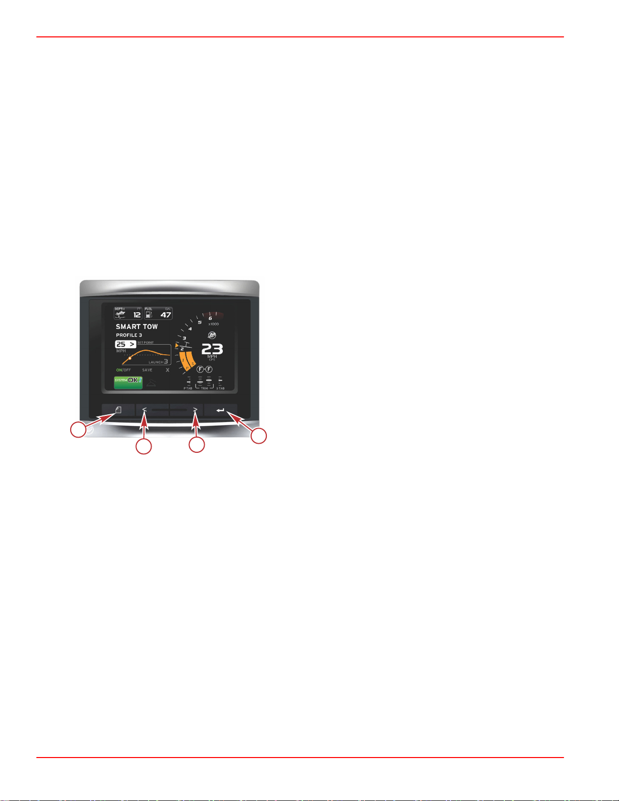
Buttons
VesselView 4
a - PAGES button
b - LEFT arrow button
c - RIGHT arrow button
d - ENTER button
• Pressing the PAGES button will activate the scroller bar menu. Pressing the PAGES button again exits the scroller bar
menu.
• Use the LEFT and RIGHT arrow buttons to navigate (highlight) fields on the screen.
• Press the ENTER button when the desired icon is highlighted to enter that data field or function.
Page 2 90-8M0120668 eng MARCH 2016
Page 7
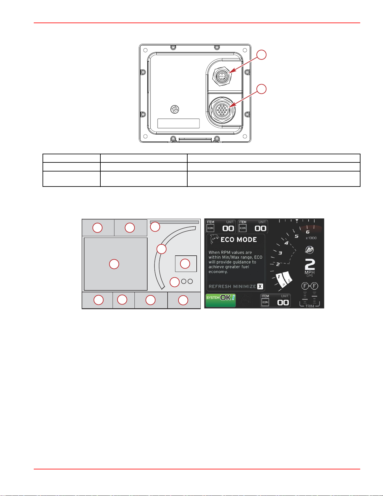
Rear Panel
a
b
55835
51378
13456
7
8
91011
2
Item Function Description
a NMEA 2000 Connects to NMEA 2000 network
b SmartCraft
Power input and connects to the SmartCraft network, links SC 100
gauges
Section 1 - Getting Started
VesselView 4 Screen Display Locations and Descriptions
VesselView has multiple fields that display specific engine information and active modes.
1. Volts or depth: This data field is user definable. A list of the available display content can be modified in the Settings menu.
• Volts will appear out of the field only when a depth transducer is installed.
• Depth will be replaced by volts if a depth transducer is not installed or had been uninstalled.
2. Fuel: This data field is user definable. A list of the available display content can be modified in the Settings menu.
• Displays total fuel only. Individual fuel data will be located on‑screen under fuel management.
3. Steering angle: If installed, the user can select maximum limits of 45° or 60°, and invert the angle. The steering angle will
be available if the sensor is installed and monitored by the control module. When an outboard engine is the installed power
package, this feature will be turned off by default, but can be manually turned on in the Settings menu.
4. RPM: Displays a moving bar representing the engine RPM. A dual‑engine application will show two separate moving bars.
5. Speed: Displays the speed of the vessel. If a speed source is not available, the display will show dashes. The display will
show the speed value, the speed source (paddle wheel, pitot, or GPS), and the units of measurement (MPH is the default).
A speed value with more than two integers will be shown in smaller fonts.
6.
Gear position: DTS products will display all gear positions for each engine. The positions are defined as F (forward), N
(neutral), and R (reverse). Non DTS products will show N (neutral) and G (in gear).
7. Trim: This data field is user definable. Displays trim for up to two engines. Trim pop‑up is available in the contextual data
area. Trim pop‑up can be turned off or on in the Settings menu.
8. Tabs: This data field is user definable. A list of the available display content can be modified in the Settings menu.
90-8M0120668 eng MARCH 2016 Page 3
Page 8
Section 1 - Getting Started
2.043.301
MERCURY MARINE
55831
56943
• If installed, the port tab will be displayed on the left side of the trim data and the starboard tab will be displayed on the
right side of the trim data.
9. Scroller bar icon: Displays an icon representing the data currently displayed in the selected data area of the screen. Press
the PAGES button to open the scroller bar. The user can choose another icon in the scroller bar and the selected data will
then be displayed.
10. System status field: Displays the current active mode and warnings.
11. User‑selected data area: Displays all selected data, including initial start up scan progress, good stewardship messages,
maintenance schedules, and warnings.
How to Update Your VesselView 4 Software
The following instructions explain how to upgrade the VesselView 4 software. Internet access is required, along with a
communication port used to transfer the file to a FAT or FAT 32 micro SD card.
Obtaining the Latest Software
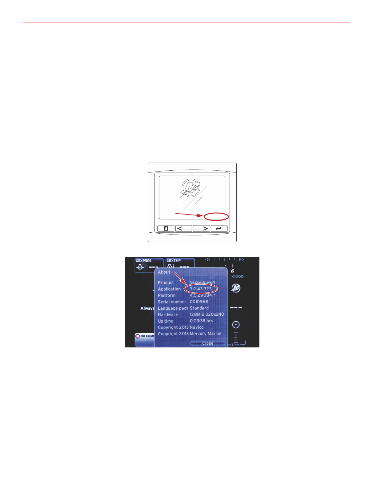
1. The latest software for the display is available on‑line for general download at Mercury's website;
www.mercurymarine.com. To determine what software version is in VesselView, power up VesselView. While the system
boots up, the screen will show the software version in the lower right‑hand corner. If VesselView is already powered up,
select Settings>System>About to see the current operating version of the VesselView software.
2. Select the VesselView 4 product and click on DOWNLOAD UPGRADE.
3.
Depending on your computer’s security settings, a security warning may appear. Click Allow to continue.
4. Create a folder on your hard drive to save the file to.
5. If you are asked to SAVE or RUN, select SAVE and save to your hard drive.
NOTE: The file is typically 20–40 MB in size.
IMPORTANT: Some browsers may change the file extension. Verify that the file name and extension have not changed.
The correct extension after the file name should be .upd. Do not rename the file or change the extension.
6. After the file is saved to the hard drive, copy the file to a 512 MB or higher capacity blank FAT or FAT 32 micro SD card
root. The root of the drive is the topmost level, and not placed into a folder.
Upgrading VesselView
Important considerations before and during the upgrade process:
Page 4 90-8M0120668 eng MARCH 2016
Page 9

Section 1 - Getting Started
Update in progress.
Please do not remove
the SD card or power off
during this process.
56561
Update complete.
Please remove the SD card to finish.
56563
• Each display must be upgraded individually, there is no automatic network feature to upgrade multiple VesselView's
simultaneously.
• Do not turn off the display or disrupt the power during the upgrade process.
• Do not remove the micro SD card during the upgrade process.
1. Verify that the ignition key is off and that VesselView is not turned on.
NOTE: Some installations may have the VesselView powered up with a dedicated circuit, rather than by the ignition key‑on
circuit.
IMPORTANT: VesselView must be turned off for a minimum of 30 seconds before upgrading the software.
2. Insert the micro SD card into the card reader port all the way until it clicks and stays in place.
3. Turn the ignition key on and verify that VesselView is on.
4. Allow the system to boot up. The update process is automatic.
5. Do not turn the ignition key off, turn VesselView off, or remove the micro SD card while the software is uploading. The
upgrade process may take several minutes to complete.
6. When the upload is finished, remove the micro SD card and the system will automatically reboot to complete the upgrade.
7. Verify that the software version upgraded is the correct version. Press the PAGES key and use the RIGHT arrow to scroll
to the Settings menu. Use the ENTER button and arrow buttons to highlight System and open About. The current
software version will be listed.
Installing the Ambient Air Temperature Sensor
NOTE: The ambient air temperature sensor installation is optional.
1. Select the location for the air temperature sensor. Mount the sensor where it will be exposed to outside air and not in direct
sunlight.
2. Drill a 19 mm (0.75 in.) mounting hole.
90-8M0120668 eng MARCH 2016 Page 5
Page 10
Section 1 - Getting Started
52721
a
b
c
d
10738
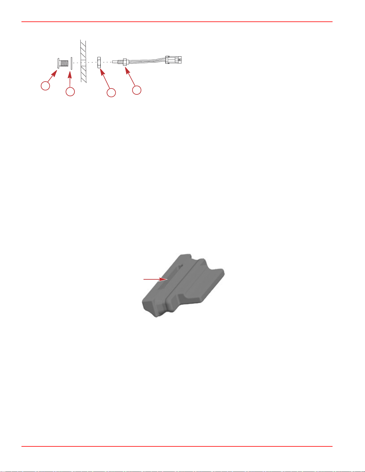
3. Install the mounting adapter as shown below.
a - Mounting adapter
b - Gasket
c - Nylon nut
d - Air temperature sensor
4. Thread the sensor into the mounting adapter.
5. Connect the temperature sensor to the connector on the VesselView harness.
Maintenance
IMPORTANT: It is recommended that the supplied sun cover be installed for protection when the unit is not in service.
Display Screen Cleaning
Routine cleaning of the display screen is recommended to prevent a buildup of salt and other environmental debris. Crystalized
salt can scratch the display coating when using a dry or damp cloth. Ensure that the cloth has a sufficient amount of fresh water
to dissolve and remove salt deposits. Do not apply aggressive pressure on the screen while cleaning.
When water marks cannot be removed with the cloth, mix a 50/50 solution of warm water and isopropyl alcohol to clean the
screen. Do not use acetone, mineral spirits, turpentine type solvents, or ammonia based cleaning products. The use of strong
solvents or detergents may damage the anti‑glare coating, the plastics, or the rubber keys.
It is recommended that the sun cover be installed when the unit is not in use to prevent UV damage to the plastic bezel and
rubber keys.
Media Port Cleaning
The media port door area should be cleaned on a regular basis to prevent a buildup of crystalized salt and other debris. A red
rubber composite plug inside the micro SD card port helps prevent water intrusion into the card port.
IMPORTANT: Install the plug after cleaning, or after updating the software.
NOTE: Install the plug with the groove side up. The opposite side has a chamfer so the door does not collide with the plug.
Stuck Buttons
Verify that there are no buttons stuck in the down position. If a stuck button is found, wiggle the button to free it.
Page 6 90-8M0120668 eng MARCH 2016
Page 11

Section 2 - Initial Screens and Setup Wizard
Table of Contents
Section 2 - Initial Screens and Setup Wizard
Splash Screen........................................................................ 8
Setup Wizard.......................................................................... 8
Import Configuration ..................................................... 10
Engine Setup ................................................................ 10
Display Setup ............................................................... 12
Device Setup ................................................................ 12
Units Setup ................................................................... 13
Tank Configuration ....................................................... 13
Speed Setup ................................................................. 15
Finishing Setup Wizard ................................................. 16
Data Source Setup ....................................................... 16
Startup Display Screens....................................................... 16
Startup........................................................................... 16
Engine Off, Ignition On .......................................... 17
Engine Running at Idle .......................................... 17
Engine Fault...................................................................18
Fault Navigation .................................................... 18
Engine Scheduled Maintenance.................................... 18
System Scan ‑ Scan Report.......................................... 19
Communication Errors ........................................... 20
2
90-8M0120668 eng MARCH 2016 Page 7
Page 12
Section 2 - Initial Screens and Setup Wizard
51617
56815
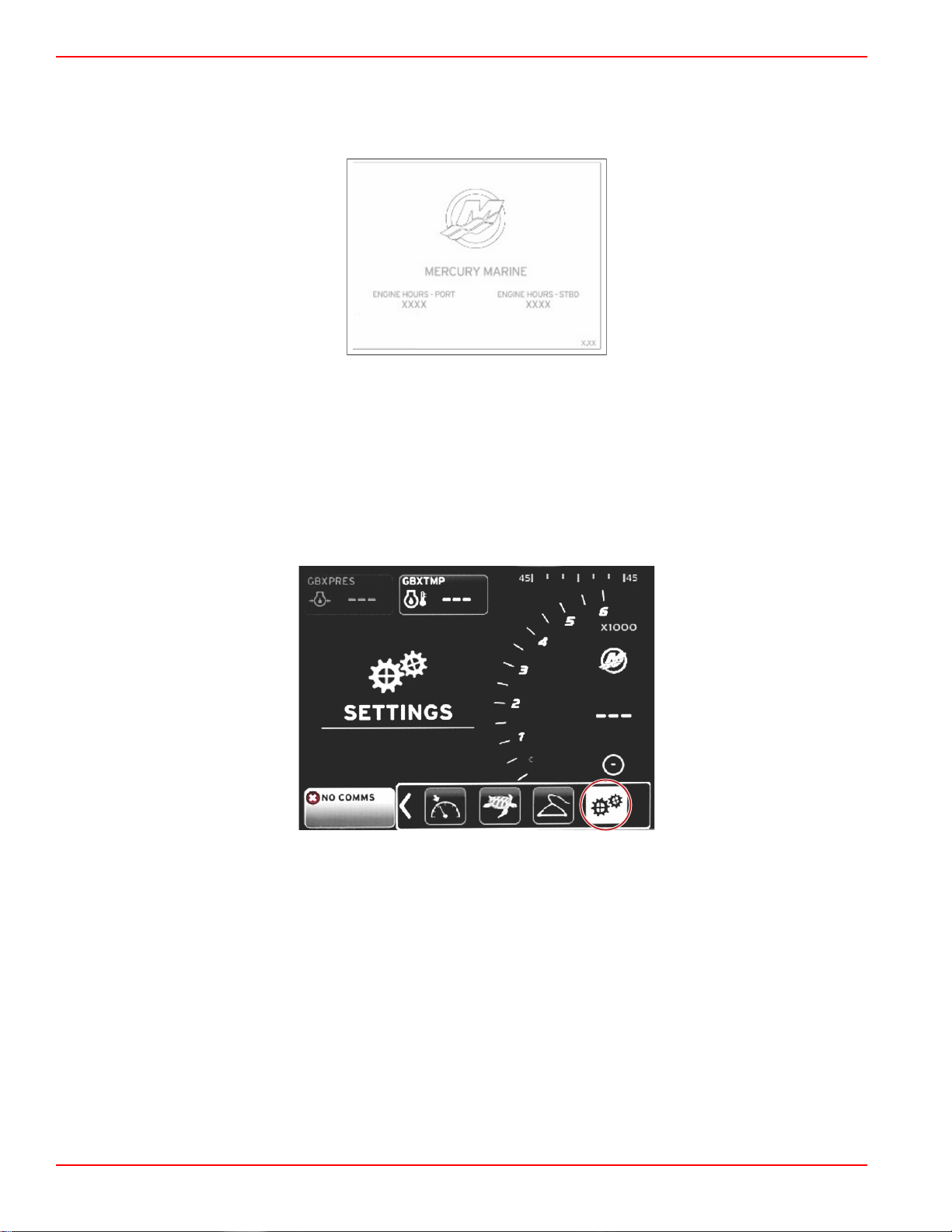
Splash Screen
When the ignition key is turned on, a Mercury startup splash screen will appear. The number of operation hours is supported up
to 9,999 hours. In the lower right‑hand corner of the screen is the software version. Power packages with emissions control will
show an engine icon in the lower left‑hand corner of the screen.
Mercury splash screen
Setup Wizard
IMPORTANT: Do not rush VesselView by pressing buttons while the system is booting up to acquire vessel and engine data.
When VesselView is initially started or after a factory reset, the system will take a few seconds to complete the boot up
process.
The VesselView setup wizard guides you through the first steps of configuring the VesselView. The Setup wizard can be
accessed at any time through the SETTINGS icon in the scroller menu. Press the PAGES, RIGHT ARROW, and ENTER
buttons to navigate to the Settings menus.
Page 8 90-8M0120668 eng MARCH 2016
Page 13
Section 2 - Initial Screens and Setup Wizard
56823
56793
56792
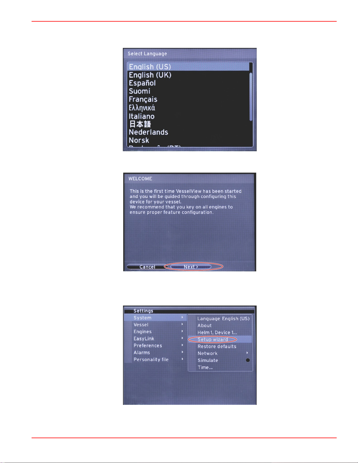
1. Select the language that you want VesselView to display. Use the LEFT and RIGHT arrow buttons to scroll through the
language choices. Press the ENTER button to make the selection. VesselView will ask for language change confirmation
and restart. The Restarting screen will appear. When the display returns, all text will be in the selected language.
2.
A welcome screen will appear. Press the RIGHT arrow to highlight the Next field.
3. The main VesselView screen will appear in the selected language. The SETTINGS icon will be highlighted. Press the
ENTER button. System will be highlighted in the Settings menu. Press the ENTER button and the flyout menu will appear.
Press the RIGHT arrow button to scroll down to Setup wizard.
90-8M0120668 eng MARCH 2016 Page 9
Page 14
Section 2 - Initial Screens and Setup Wizard
56794
60111
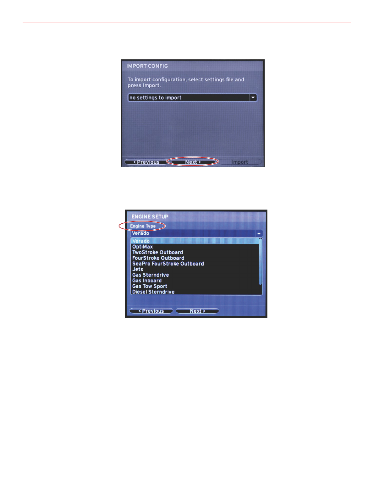
Import Configuration
To import an existing vessel configuration, insert a micro SD card with the configuration file and select this file in the drop‑down
menu. If there is no import file, use the RIGHT arrow button to highlight Next and press ENTER.
Engine Setup
1.
In the Engine Setup screen, press the RIGHT and LEFT arrow buttons to highlight the drop‑down fields. Make selections
based on the engine type and model.
Engine type selection
Page 10 90-8M0120668 eng MARCH 2016
Page 15
Section 2 - Initial Screens and Setup Wizard
60112
60113
60114
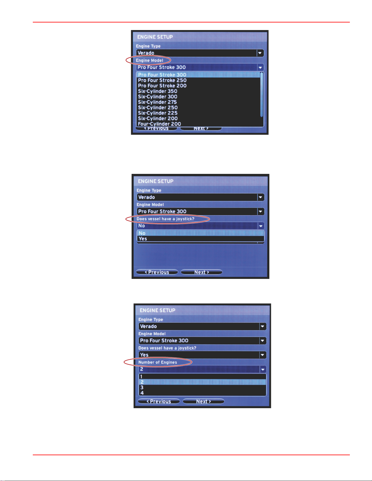
Engine model selection
2.
Scroll down to complete selections in the Engine Setup screen. When all selections have been made, highlight Next and
press ENTER.
Joystick option selection
Number of engines selection
90-8M0120668 eng MARCH 2016 Page 11
Page 16
Section 2 - Initial Screens and Setup Wizard
60116
a
b
56802
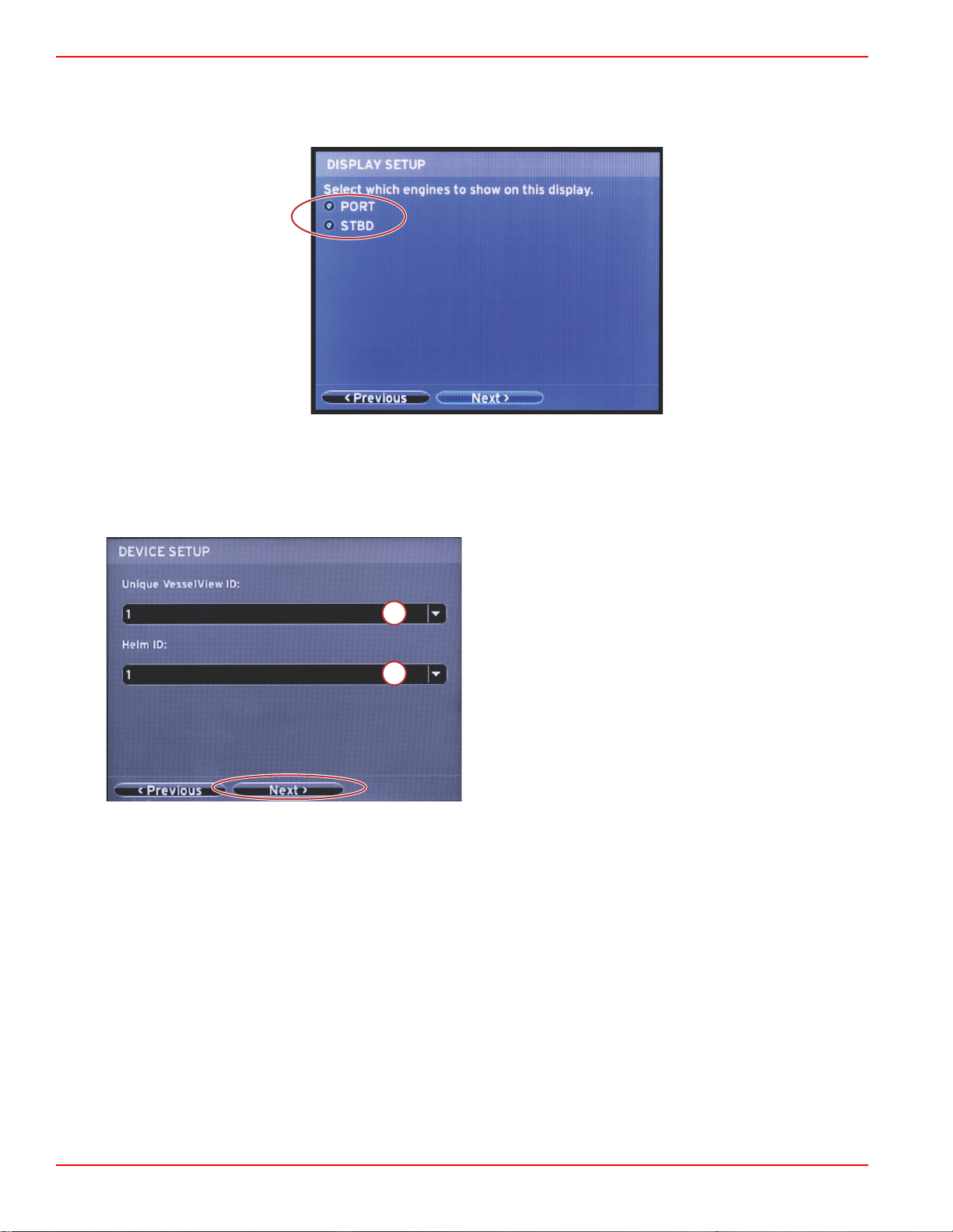
Display Setup
Depending on the number of engines indicated in the Engine Setup screen, select the engines to be displayed by this
VesselView unit. Up to two engines can be selected.
Device Setup
In the Device Setup screen, use the RIGHT and LEFT arrow buttons to highlight the drop‑down menus. If using multiple
VesselView devices, be sure to assign unique numbers to each unit, to avoid data problems. Helm numbers should match the
location of the individual VesselView unit. Highlight Next and press ENTER to continue.
a - VesselView device number
b - Helm location number
Page 12 90-8M0120668 eng MARCH 2016
Page 17
Section 2 - Initial Screens and Setup Wizard
60119
60120
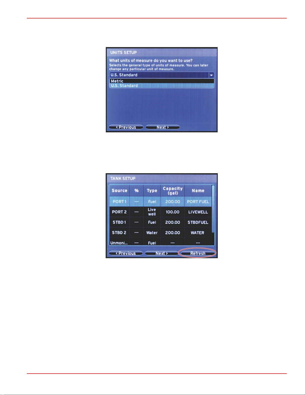
Units Setup
Select the units of measure that VesselView will display on‑screen data; speed, distance, and volumes. Individual units of
measure can be changed later. After selecting the units of measure, highlight Next and press ENTER.
Tank Configuration
In the Tank Setup screen, tank type, capacity, and tank name can be assigned for up to eight tanks. The % column will display
the live tank volume. Selecting the Refresh button will query the tank sensors and refresh the readings.
The unmonitored tank is a tank that does not have a sensor associated with it.
90-8M0120668 eng MARCH 2016 Page 13
Page 18
Section 2 - Initial Screens and Setup Wizard
60121
60122
60123
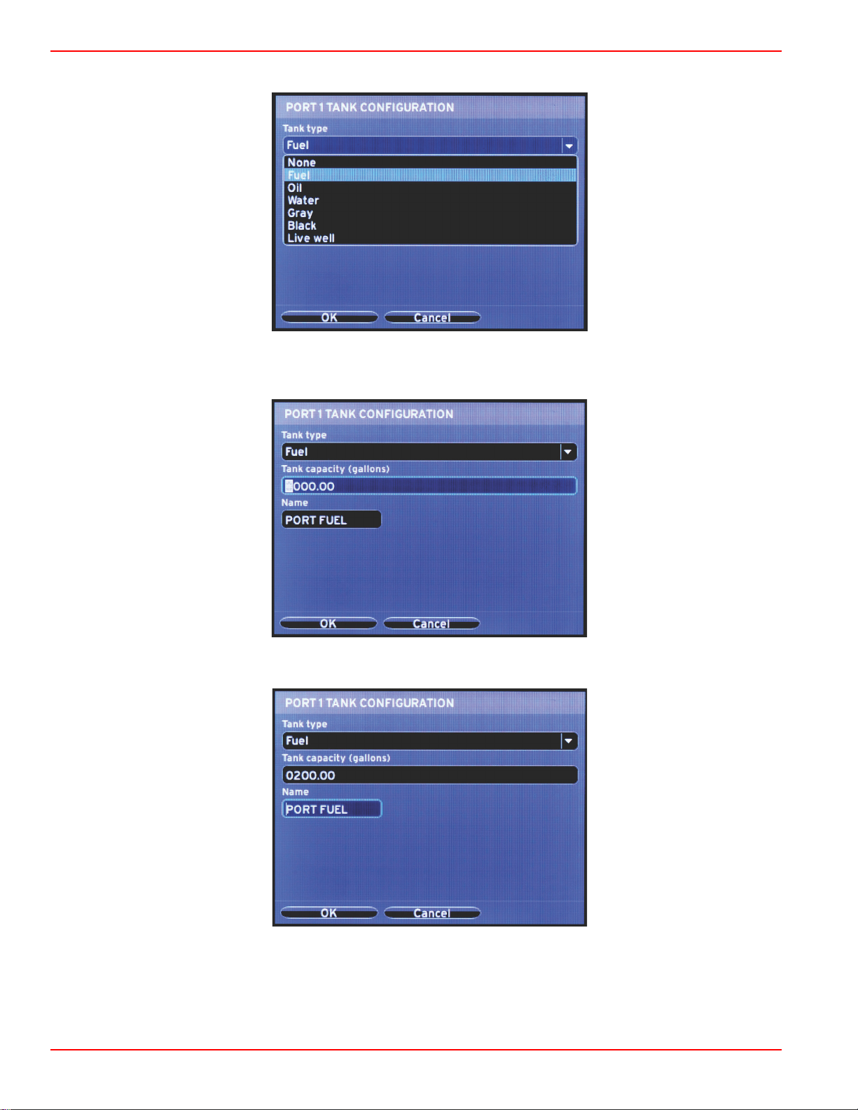
Use the arrow buttons to toggle through the tank type options.
Enter the tank capacity by using the arrow buttons to change the digits. Use the ENTER button to continue to the next digit.
When finished changing digits, press the ENTER button to continue.
Select the Name window, and use the arrow buttons to toggle through the character set.
Page 14 90-8M0120668 eng MARCH 2016
Page 19
Section 2 - Initial Screens and Setup Wizard
60124
60125
56810
a
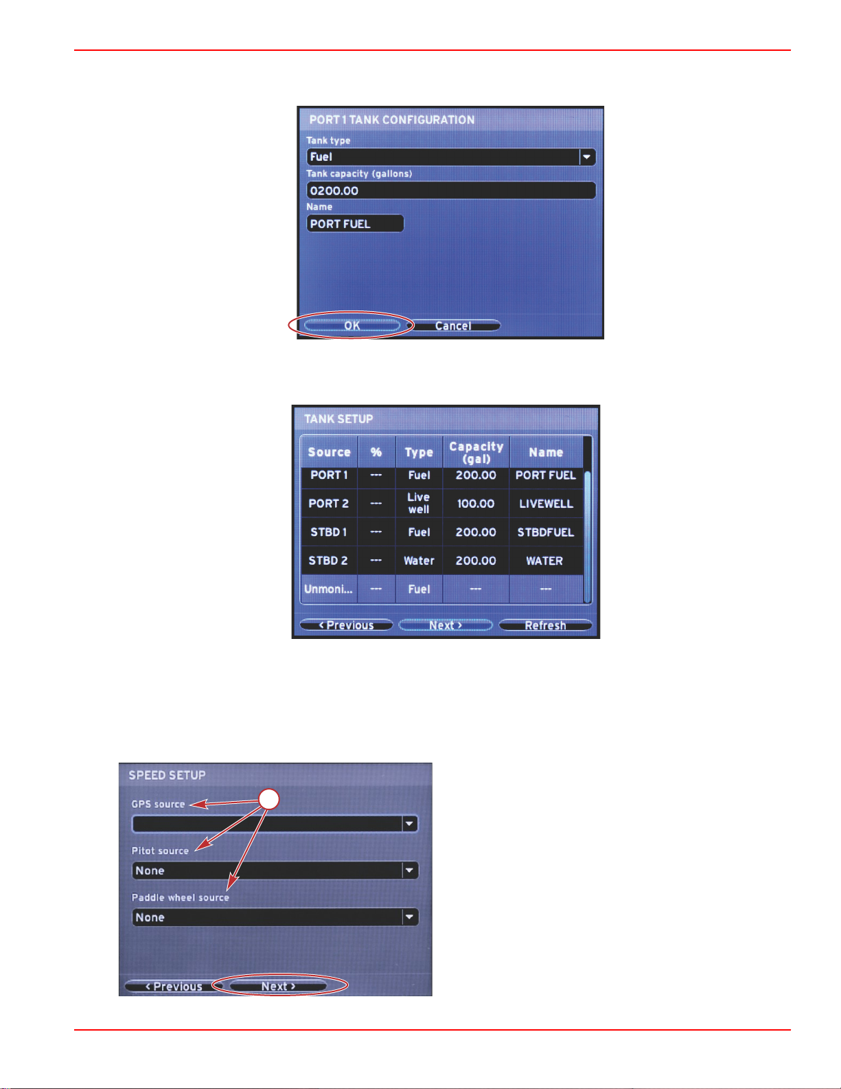
Select the OK button using the arrow buttons and the ENTER button. This will bring the operator back to the tanks selection
screen to complete the configuration of an additional tank.
Repeat the process to assign tank type, capacity, and tank name for the remaining tanks on the vessel. When complete, select
the Next button to continue with the Setup wizard.
Speed Setup
In the Speed Setup screen, there are three options for determining how VesselView will acquire speed information. If the
vessel is equipped with a GPS, the drop‑down menu will allow selection of available devices. If the vessel is equipped with a
pitot sensor, this option will be selected. If the vessel is equipped with a paddle wheel, then an option to select will drop down.
After the speed source has been selected, highlight Next and press ENTER to continue.
a - Options for speed data
90-8M0120668 eng MARCH 2016 Page 15
Page 20
Section 2 - Initial Screens and Setup Wizard
60128
60129
aaa
bbb
c
c
d
60056
a
a - PCM0 = starboard outer
b - PCM1 = port outer
c - PCM2 = starboard inner or center
d - PCM3 = port inner
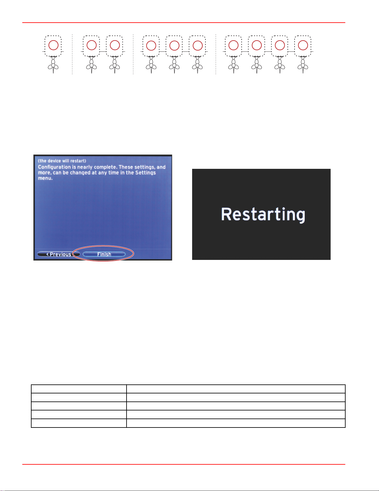
Finishing Setup Wizard
Highlighting Finish using the RIGHT arrow button and pressing ENTER will complete the Setup wizard on the VesselView. A
Restarting screen will appear. Do not power off the unit until the Restarting screen is replaced by the vessel activity screen.
Data Source Setup
Power on all products and key‑on all engines to ensure that all data generating sources can be detected.
VesselView will ask to setup detectable data sources. Select OK to continue.
Select Start to begin the process.
NOTE: If Cancel is selected by accident, data source setup can still be completed by navigating to
Settings>System>Network>Auto select. Auto select will scan the vessel network and identify all compatible devices onboard.
When Auto select is complete, select Close.
Startup Display Screens
Startup
On startup after the splash screen sequence, the main display will load and all data and graphics will be active. Two conditions
are available: engine off or engine running. The following chart and information explain the sequence for how the constant and
user‑selected data areas change.
Engine state
Engine off, ignition on Good stewardship message
Engine cranking System scan in progress, animated propeller is shown
Engine running at idle Propeller color turns green
Engine running in gear Level 1 smart contextual data
User selected data area
Page 16 90-8M0120668 eng MARCH 2016
Page 21
Section 2 - Initial Screens and Setup Wizard
52724
a
b
51618
Engine Off, Ignition On
The Mercury good stewardship message screen is displayed in the user‑selected data area when the ignition is on and the
engines are not running. All functions will be available and there will be no engine data displayed.
• The messages are randomly selected. Examples include: Do you have flotation devices, Mercury reminds you to please
boat safely.
• The good stewardship list items are subject to change depending on engine type or personality configuration.
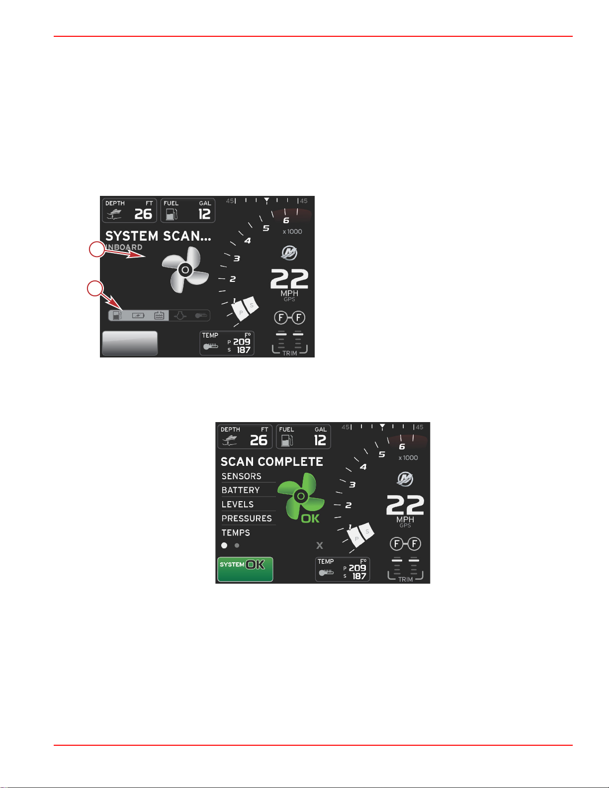
Engine Running at Idle
When the engine is running, the user‑selected data area of the display will show a green propeller when the system scan report
is finished.
• The user‑selected data area of the screen will display an animated propeller and progress bar to indicate a scan is in
progress.
System scan
a - Animated propeller
b - Progress bar
• If at anytime the engine is shifted into gear, the system scan will stop and the propeller will turn green and Level 1 smart
data will appear.
• When the scan is complete, various pop‑ups can appear: engine faults, maintenance reminders, communication errors,
system OK scan report.
Scan complete
90-8M0120668 eng MARCH 2016 Page 17
Page 22

Section 2 - Initial Screens and Setup Wizard
51619
abcde
51606
abc
d
51622
a
b
c
Engine Fault
If an engine fault is detected during a system scan, the user‑selected data area will display descriptive text in a bold color fault
screen. The color of the fault screen will depend on the type of fault detected. The system status field will change according to
the fault that is displayed.
a - Warning icon with fault title
b - Short text or legacy text
c - Engine fault location
d - Action text
e - Number of faults
Fault Navigation
When faults are present, they will be identified with numbers along the bottom footer of the fault field.
1. The selection tab will default to the first number.
2. Press the LEFT or RIGHT arrow button to review each fault.
a - PAGES button
b - LEFT arrow button
c - RIGHT arrow button
d - ENTER button
3. The selected fault will have a white filled box with a black number.
4. The selected fault will alternate between the fault number and a positive (+) symbol indicating there is more data to display.
a - Number of faults in footer
b - Selected fault
c - Exit icon for the fault footer
5. When a positive (+) symbol is available, press the ENTER button to view the additional data related to that fault.
6. When the additional data requires more pages, the fault footer area will show one or more circles. The selected page circle
will be white. This area will show the long text description of the fault.
7. To exit the fault footer, use the LEFT or RIGHT button to highlight the X in the fault footer. Press the ENTER button to exit
the fault footer and return to the system status field.
Engine Scheduled Maintenance
If a maintenance reminder is detected during a system scan, the user‑selected data area will display descriptive text in a bold
color. The system status field in the lower left corner will change according to the maintenance issue that is displayed. Use
common sense to protect your investment, and check your engine oil on a regular basis, preferably before each use.
Page 18 90-8M0120668 eng MARCH 2016
Page 23

Section 2 - Initial Screens and Setup Wizard
52447
52448
56985
1. When the scheduled maintenance time is fully depleted, the user‑selected data area will display a general maintenance
reminder to perform the scheduled maintenance.
2. Open the + icon to expand the text. You can reset the maintenance to 100% or exit the screen.
NOTE: The wrench icon maintenance reminder will be displayed in the system status field until the fault is cleared from the
system.
3. After resetting the maintenance reminder, the wrench icon no longer appears in the system status field.
System Scan ‑ Scan Report
When a system scan is completed and there are no faults, maintenance reminders, or communication errors, the user‑selected
data area will display SCAN COMPLETE with a report and a good stewardship message. The scan report will be displayed until
the engine is put into gear or use the LEFT or RIGHT arrow button to highlight the X and press the ENTER button
• The good stewardship messages are randomly selected. Examples include: Do you have flotation devices, Mercury
reminds you to please boat safely.
90-8M0120668 eng MARCH 2016 Page 19
Page 24

Section 2 - Initial Screens and Setup Wizard
51646
51653
• The good stewardship list items are subject to change depending on engine type or personality configuration.
Scan complete Good stewardship message
Communication Errors
When a system scan encounters a communication error, the scan will stop and all data fields will be displayed with dashed
lines. The system status field will be gray with an X in a red circle and text reading Comm Error.
Communication error
Page 20 90-8M0120668 eng MARCH 2016
Page 25

Section 3 - Screen Overview and Operation
Table of Contents
Section 3 - Screen Overview and Operation
System Status Field Functionality........................................ 22
Enlarging Data Fields........................................................... 23
Auto Cycle .................................................................... 23
Scroller Bar Functionality...................................................... 24
Scroller Bar Activation and Navigation ......................... 24
User‑Selected Data Area .............................................. 24
Final User‑Selected Data Selection ...................... 24
Scroller Bar Icons................................................................. 25
X‑Pand .......................................................................... 25
Temperatures ............................................................... 25
Pressure ....................................................................... 25
Voltages ........................................................................ 25
Fuel ............................................................................... 25
Tanks ............................................................................ 25
Advanced ...................................................................... 25
Performance ................................................................. 26
Trim and Tabs .............................................................. 26
Trip Log ........................................................................ 26
Navigation ..................................................................... 26
Generator ..................................................................... 26
ECO .............................................................................. 26
Autopilot ........................................................................ 26
Cruise ........................................................................... 27
Troll ............................................................................... 27
Smart Tow .................................................................... 27
Settings ......................................................................... 27
Economy Mode..................................................................... 27
ECO Mode..................................................................... 27
ECO Minimum and Maximum Values ................... 28
ECO RPM and Trim Targets..........................................28
Target Colors ......................................................... 29
ECO Navigation............................................................. 30
ECO Refresh ......................................................... 30
Minimize ................................................................ 31
Exit ECO ................................................................ 31
Changing ECO Targets................................................. 31
Changing Target Values ........................................ 32
Smart Tow Mode.................................................................. 32
Smart Tow..................................................................... 32
Features ................................................................ 32
Enabling Smart Tow .............................................. 33
Smart Tow Targets ................................................ 33
Smart Tow Overview Panel........................................... 34
Smart Tow User‑Selected Data Area............................ 35
Navigation ............................................................. 35
Save ...................................................................... 36
Create Custom Launch ......................................... 37
Disabling Smart Tow ............................................. 37
Cruise Control Mode............................................................. 37
Cruise Control................................................................ 37
Cruise Control Data Area...............................................37
Constant Data Field Change ................................. 37
Cruise—User‑Selected Data Area ........................ 38
Cruise Navigation .................................................. 38
Troll Control Mode................................................................ 40
Troll Control................................................................... 40
Troll Control Data Area.................................................. 41
Constant Data Field Change ................................. 41
Troll—User‑Selected Data Area ............................ 41
Troll Navigation ..................................................... 41
Autopilot Screens................................................................. 43
Autopilot Screens Overview...........................................43
Autopilot Screens Navigation ........................................43
Minimize Autopilot ................................................. 43
3
90-8M0120668 eng MARCH 2016 Page 21
Page 26

Section 3 - Screen Overview and Operation
51875
52099
52100
52101
52102
52104
System Status Field Functionality
The system status field is used to communicate specific engine information and active modes. It will always be visible on the
main screen in the lower left corner of the display, unless a pop‑up full screen warning is encountered. The color, icon, and text
will change according to the system status, warnings, maintenance indication, and active modes. Your vessel personality and
the type of power package installation will have a direct effect on which icons will be available in the system status field. Not all
of the available icons are listed in the following table.
System Status Examples
Engine icon when ignition is turned on. The icon is only visible if the power package has
emissions control.
Communication error when the ignition is turned on. The power package is not
communicating through the control area network.
Indicates that every component connected to the control area network is within normal
operating parameters.
Warning icon indicates that there is a fault.
Warning indicating the starboard engine onboard diagnostic has detected a fault. All other
fault identified engine locations will appear similar.
Autopilot waypoint tracking. The orange color indicates waypoint tracking is active and
computer controlled. If autopilot waypoint tracking is in standby mode (not active) the color of
the field will be gray. This color scheme change is the same for all autopilot functions.
Page 22 90-8M0120668 eng MARCH 2016
Page 27

Section 3 - Screen Overview and Operation
52094
a
b
c
52095
Enlarging Data Fields
Data fields can be enlarged by highlighting the expand (X‑PAND) icon and pressing the enter button.
Expand icon
After the icon is activated, the user‑selected data area will be filled with the enlarged data from the actively displayed data
selection. Up to six data selections can be enlarged, one at a time, and will cycle in the chronological sequence shown in the
following illustration. Data fields 3 and 4 will only display the optional user‑selected data.
NOTE: The default setting of trim and tabs will not enlarge unless they are activated with external controls. If they are activated,
a pop‑up process will be utilized. Trim and tabs pop‑ups can be turned off in the
1.
Volts or depth: This data field is user definable. A list of all available display content is available in the Settings menu.
2. The steering angle will be available if the installed sensor is connected to the SmartCraft control area network. Steering
angle is turned off by default, but can be manually turned on in the Settings menu.
3. Speed: Displays the speed of the vessel. If a speed source is not available, the display will show dashes. The display will
show the speed value, the speed source—paddle wheel, pitot, or GPS, and the units of measurement—MPH is the default.
A speed value greater than two digits will be shown in a smaller font.
4. RPM: Displays a moving bar representing the engine RPM. A dual‑engine application will show two separate moving bars.
5. Fuel: This data field displays total fuel onboard.
• Displays total fuel only. Individual fuel data will be located in the selected data area under fuel management.
6. The scroller bar allows the operator to select different Mercury application screens to open in the user‑selected data area.
Use the PAGES button and the arrow buttons to move between icons in this section of the screen.
7.
Gear position: DTS products will display all gear positions for each engine. The positions are defined as F—forward, N—
neutral, and R—reverse. Non‑DTS products will show N—neutral and G—in gear.
8. Trim: This data field is user definable. Displays trim for up to two engines. Trim pop‑up is available in the selected data
area. Trim pop‑up can be turned off or on in the Settings menu.
9. Selected data icon: Displays an icon representing the data currently being displayed in the selected data area of the
screen. It will also display the previously selected data icon if there is currently no selected data being displayed. Select the
PAGES button to open the scroller bar. The user can select an icon in the scroller bar and the selected data will then be
displayed.
10. System status: Displays the current active mode and warnings.
11. Selected data area: Displays all selected data, including initial start up scan progress, good stewardship messages,
maintenance schedules, and warnings.
12. The auto cycle icon will display all of the data screens associated with a menu selection. The display will cycle through, in
sequence, at a user‑selected time interval.
13.
The X icon will close, or exit, the current data selection.
Each data field has its own page indicator in the lower left‑hand corner of the user‑selected data area. Use the arrow buttons to
navigate to the various page or the auto cycle icon or exit icon. Press the enter button when the auto cycle or exit icon are
highlighted.
Settings
menu.
Page indicators
a b - Auto cycle icon
c - Exit icon
Auto Cycle
• When auto cycle is selected but not active, the icon will be displayed on a white field.
• Press the enter button to activate the auto cycle. The icon will be displayed on a blue field with white arrows and will
remain this color scheme until auto cycle is disabled. The default time for auto cycle is five seconds per page and can be
changed in the Settings menu.
90-8M0120668 eng MARCH 2016 Page 23
Page 28
Section 3 - Screen Overview and Operation
b
a
52051
• When the auto cycle is active, the arrow buttons are not available. Highlight one of the pages and press the enter button.
Auto cycle remains active but is not visible. To return to the auto cycle, highlight the auto cycle icon and press the enter
button.
• To turn off auto cycle, highlight the X and press the enter button. The screen will exit the user‑selected data area.
Scroller Bar Functionality
The scroller bar provides access to items not currently displayed in the user‑selected data area of the screen. The item will be
hidden until activated and will be displayed for the amount of time the user has selected in the Settings menu. If there is no
activity for more than five seconds, the icon item in the user‑selected data area will transition off. When active, the
user‑selected data area will be transformed to show the icon name and data pertaining to that feature.
Scroller Bar Activation and Navigation
1. Press the PAGES button to activate the scrolling bar menu.
2. Use the LEFT or RIGHT arrow buttons to highlight the icon you would like displayed. A blue outline will highlight the
scroller bar icon to be selected.
NOTE: An arrow icon will appear to the left and right of the scroller bar. When only one arrow icon is visible, you must use
the indicated arrow button to move the selection. When both arrows are visible, either arrow button can be used.
a - Selected icon
b - Scroller bar arrows
User‑Selected Data Area
During the scroller bar navigation process, when the icon is highlighted and the enter button is not pressed, the user‑selected
data area will change to display the icon, the icon name, and description of what the feature does. The user‑selected data area
will show this information for up to 30 seconds. The duration of time that the highlighted user‑selected data and corresponding
scroller bar will remain on‑screen without pressing the enter button can be set by navigating to Preferences>Scroller Bar>Auto
hide delay.
Final User-Selected Data Selection
When the icon has been selected, press the enter button. The icon will show up next to the system status field and the
user‑selected data area will display the full data pertaining to that selection.
Page 24 90-8M0120668 eng MARCH 2016
Page 29

Section 3 - Screen Overview and Operation
60706
60707
60709
60710
60711
60713
60714
Scroller Bar Icons
X‑Pand
X‑pand—displays enlarged data from selected data screens. Selected data will cycle on‑screen.
Temperatures
Temperatures—displays engine and fluid temperature values for oil, water, and fuel. Displays environmental air and manifold
air temperature. Available information is power‑package dependent.
Pressure
Pressure—displays engine pressure values for water, oil, fuel, and boost. Available information is power‑package dependent.
Voltages
Voltages—displays battery values for all engines.
Fuel
Fuel—displays fuel system statistics: current economy, average economy, volume use per hour, total capacity, and fuel used.
Tanks
Tanks—displays the vessel's onboard tanks data for fuel, water, waste, and two‑cycle oil capacity.
Advanced
Advanced—displays additional engine information: manifold temperature, throttle percent, engine load, and manifold boost
pressure. Available information is power package dependent.
90-8M0120668 eng MARCH 2016 Page 25
Page 30

Section 3 - Screen Overview and Operation
60715
60717
60719
60720
60721
60722
Performance
Performance—displays advanced performance data: peak performance—RPM or speed and inches per revolution of the
propeller.
Trim and Tabs
Trim and tabs—displays drive trim position and position of tabs. A sensor must be installed on the tabs for this function to
display information.
Trip Log
Trip log—displays recorded trip data: total distance, total time, average speed, average fuel consumption. Trip log recorded
data can be erased and set to zero.
Navigation
Navigation—displays data relating to the installed navigation system: compass heading, longitude and latitude, time to waypoint
(TTW), bearing to waypoint (BTW), distance to waypoint (DTW), and course over ground (COG).
Generator
Generator—displays data the generator can send through a NMEA 2000 or J1939 protocol control area network: current run/
stop state, voltage—AC/DC, hertz, hours, oil pressure, and water temperature.
ECO
ECO—displays information to guide the operator to the best trim position and engine speed to achieve the best fuel economy.
NOTE: Refer to
Economy Mode
in this section for additional operating information.
Autopilot
Autopilot—displays autopilot data.
Page 26 90-8M0120668 eng MARCH 2016
Page 31

Section 3 - Screen Overview and Operation
60723
60724
60725
60726
60727
57376
NOTE: Refer to
Autopilot Mode
in this section for additional operating information.
Cruise
Cruise—activates cruise control. Allows the user to control the vessel with the engine RPM or vessel speed. Vessel speed
control requires a paddle wheel sensor or GPS.
NOTE: Refer to
Cruise Control Mode
in this section for additional operating information.
Troll
Troll—activates low‑speed engine control. Can be used to control engine RPM.
NOTE: Refer to
Troll Control Mode
in this section for additional operating information.
Smart Tow
Smart Tow—activates Smart Tow profiles for selection. Profiles can be modified, added, and saved.
NOTE: Refer to
Smart Tow Mode
in this section for additional operating information.
Settings
Settings—the main location where data can be turned on or off, modify sensor data tolerance ±, select preferred displayed
values—metric/English/nautical, and reset to factory default.
NOTE: A reset to factory default will erase all customized settings. Refer to Section 4 for details.
Economy Mode
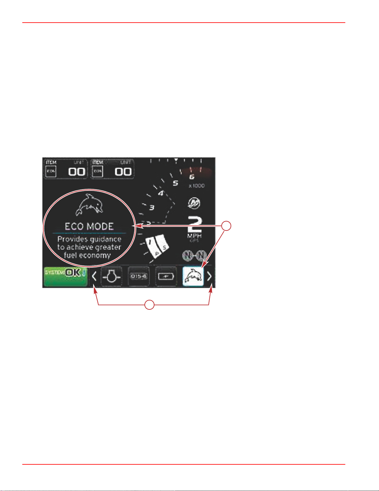
ECO Mode
ECO mode displays information to guide the operator to the optimum trim position and engine speed to achieve the best fuel
economy. The engine control module (ECM) or propulsion control module (PCM) calculates the best fuel economy based on
information from various sensors on the power package and vessel.
1. Press the PAGES button to activate the scroller bar.
90-8M0120668 eng MARCH 2016 Page 27
Page 32

Section 3 - Screen Overview and Operation
52165
52166
52167
2. Press the arrow button to highlight the ECO icon and press the enter button. The user‑selected data area will display the
ECO icon element with a short description on how to achieve the best fuel economy.
NOTE: When ECO mode is active, system footer data field 4 location will default to displaying trim values, if another data
value is currently being displayed. Trim values will be displayed in the bottom right corner of the screen if another data
value is currently being displayed.
ECO mode active trim values
ECO Minimum and Maximum Values
When ECO mode is active and the engines are in forward gear, the minimum and maximum value lines will appear in the RPM
sweep. These lines display the active optimized range that is to be calculated. This window can be adjusted in the Settings
menu.
ECO RPM and Trim Targets
When the RPM values reach the minimum value range, RPM and trim targets will appear. A colored line will span the RPM
sweep with colored targets to inform the user where the target values are and will change color when they have achieved
optimization.
Page 28 90-8M0120668 eng MARCH 2016
Page 33

Target Colors
52171
52172
52173
State Color Fill value Action Image
Section 3 - Screen Overview and Operation
Triangle Color Rules
Target not
achieved
Yellow Outline Blinking
Target achieved Green Solid Continuous
The following are examples of ECO RPM targets in different states.
Not optimized
The user‑selected data area will display the trim targets.
Optimized
90-8M0120668 eng MARCH 2016 Page 29
Page 34

Section 3 - Screen Overview and Operation
52174
52177
52176
b
a
c
When all targets have been achieved, the user‑selected data area screen will change from instructions, to displaying
OPTIMIZED with the current fuel economy value.
ECO Navigation
The user‑selected data area footer will display REFRESH, MINIMIZE, and X. Use the pages, arrow, and enter buttons to
navigate these features.
• Minimize will hide ECO instructions and display ECO MODE in the system status field. Minimize allows the user to display
other information in the user‑selected data area.
• Refresh will reset the ECO values and use new parameters for determining the RPM and trim target values.
• X will close ECO mode, removing the RPM and trim targets from the constant data area.
• The active area will have a white border.
a - Refresh
b - Minimize feature active
c - Exit
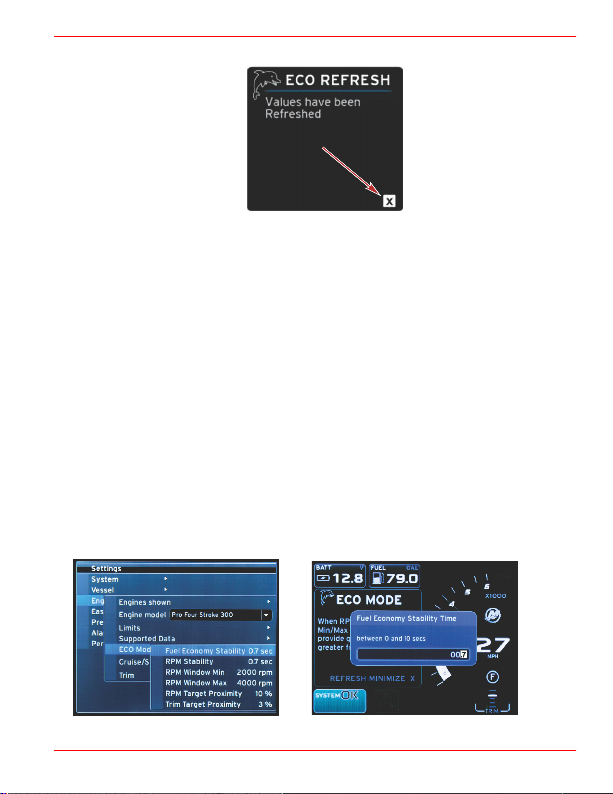
ECO Refresh
Refresh allows you to recalculate the current values that ECO uses for the RPM and trim targets.
1. Use the arrow buttons to highlight the refresh feature and press enter.
2. Instructions appear in the user‑selected data area. Use the arrow button to highlight the refresh feature and press enter.
3. When the system has finished calculating new targets, the user‑selected data area will change to indicate that the values
have been refreshed.
Page 30 90-8M0120668 eng MARCH 2016
Page 35
Section 3 - Screen Overview and Operation
52178
60837
60838
4. Highlight the X and press enter to return to the main ECO instruction screen.
5. The ECO user‑selected data area will show instructions and show new target values on how to achieve optimization for the
best economy.
Minimize
Minimize is a feature that allows the user to continue with the ECO features while displaying additional information in the
user‑selected data area.
1. When minimize is selected, the ECO instructions will be removed and then display additional information in the
user‑selected data area. You can also select limited items from the scroller bar.
• Scroller bar selection is limited to: Expand, Fuel Management, Trip Log, Voltage, Navigation, Pressure, Temperature,
Tanks, and Generator.
NOTE: The items available on the scroller bar are dependant on information available from the gauge and vessel
personality.
• Items displayed in the scroller bar that are gray when ECO is active, are unavailable and cannot be selected.
2. When minimize is active, the system status field will display ECO.
3. To enlarge ECO mode, use the arrow buttons to highlight the ECO icon and press the enter button.
4. When ECO achieves optimization, the user‑selected data area text will change to OPTIMIZED.
Exit ECO
To exit the ECO mode, select the X in the user‑selected data area footer and VesselView will turn off the ECO function.
Changing ECO Targets
The software for ECO monitors the engine sensors and looks for the best fuel economy number while the vessel is in operation.
When the software recognizes an improvement in the fuel economy, VesselView records what the trim and engine RPM values
are at that time. This calculation happens whether the ECO screen is visible or not. When the software has recorded the RPM
and trim values, it will guide the operator with arrows, to where that optimum running speed and trim setting was. In most
applications the ECO screen does not need any calibration, although there are settings to customize the gauge for your boating
style. The default settings are within acceptable parameters for most vessel applications. The following are the default settings,
and the adjustment option which can be activated by pressing the enter button while any parameter is highlighted.
90-8M0120668 eng MARCH 2016 Page 31
Page 36

Section 3 - Screen Overview and Operation
57377
52179
Default ECO Target Settings
Fuel economy stability 0.7 seconds
RPM stability 0.7 seconds
RPM window minimum 2000 RPM
RPM window maximum 4000 RPM
RPM target proximity 10%
Trim target proximity 10%
IMPORTANT: A manual trim calibration must be performed before the ECO screen can be used if a vessel personality was not
uploaded with a micro SD card. Using a default trim calibration will not allow the ECO screen to function properly.
Changing Target Values
1. Press the PAGES button to open the scroller bar.
2. Press the arrow button to highlight the settings icon. Press the enter button.
3. Press the arrow button to highlight Network and press the enter button.
4. Press the arrow button to highlight ECO Mode and press the enter button.
5. Press the arrow button to highlight the target you want to change—RPM window minimum or RPM window maximum, and
press the enter button.
6. Press the arrow buttons to change the individual numbers (X000). Press the enter button to save that number and move to
the next number (0X00), use the arrow buttons to change this number.
7. When the last number (000X) has been changed, press the enter button.
NOTE: The
Settings
menu will close after pressing the enter button. To change other target values, press the pages
button, settings will be the icon that is highlighted. Follow the same process as previously outlined to change other target
values.
Smart Tow Mode
Smart Tow
Smart Tow is an easy to use program to manage boat acceleration and target speed goals for pulling skiers, tubers, or
watersport equipment of all varieties. Smart Tow takes the guesswork out of acceleration problems like too much hole shot, too
much overshoot, deceleration, and inconsistent speed targets. Select a profile, select enable, and place the control handle to
wide‑open throttle, Smart Tow will do the rest.
Smart Tow is based on the engine RPM unless the vessel has a GPS installed and connected to the control area network.
When the vessel contains a GPS, you can select either speed targets or engine RPM targets for Smart Tow control options.
You can also create custom launch profiles.
Features
Smart Tow utilizes the user‑selected data area and the footer section to allow you to adjust the settings. Touch or swipe to
move through the selection box fields. The footer section allows you to enable or disable Smart Tow, save, or exit. The items
located in the data area footer require the selection to be touched or use the rotary knob to highlight and select.
Page 32 90-8M0120668 eng MARCH 2016
Page 37

Section 3 - Screen Overview and Operation
52280
a
b
52180
Smart Tow offers five factory preset launch profiles, or the operator can create new custom launch profiles. Custom profiles are
helpful when there are people onboard with varying levels of experience with watersports equipment. The operator can create
more aggressive launches for experienced skiers, as well as milder launches for children, or towing inflatables.
Factory preset profiles
There are five selection fields within a profile. Use the arrow buttons and the enter button to change the profile selections.
• Set point is the RPM or speed. The operator can adjust the RPM or speed in the data screen area.
• Ramp is the time that the boat will take to get to the set point.
• Overshoot is the percentage over the set point the boat will achieve.
• Overshoot duration is the length of time that the boat will remain above the set point.
After making adjustments to the desired settings, select NEXT in the data area footer. This will take the operator to the
keyboard screen, to name and save to the profiles list. Name the profile and select the enter key to add the new profile to the
list.
Enable or disable turns the feature on or off. The RPM sweeps will be displayed as nonactive white sweeps when disabled. The
RPM sweeps will be displayed as active orange sweeps when enabled. The operator can modify all settings when Smart Tow
is in the off—disabled state.
Select SAVE. Save will modify the Smart Tow screen to allow the operator to choose quick save, save as new, create custom,
or delete the profile.
If the operator presses on the X, Smart Tow is disabled and the constant and user‑selected data area returns to the default
screen.
Enabling Smart Tow
To activate Smart Tow, select a preset launch profile or a custom‑made profile. When the vessel and person being towed are
ready, place the throttle lever in the full throttle position. Smart Tow will begin the launch profile. A moving dot will move along
the profile path, indicating the current progress of the launch profile.
1. Enable—on, is green when ready
2. Disable—off, is red when not active
The boat will continue at the set RPM or speed target until disable is selected, or until the operator moves the throttle lever to
the idle position.
Smart Tow Targets
Smart Tow will modify the constant data area by incorporating RPM and overshoot indicators within the RPM sweeps. The
RPM set point target will be the color orange and the overshoot scale will be the color white.
RPM set point target
a b - Overshoot scale
The RPM set point target will change from an outline when not active, to a solid when activated.
90-8M0120668 eng MARCH 2016 Page 33
Page 38

Section 3 - Screen Overview and Operation
52182
52183
52184
52185
RPM Set Point Target
State Color File value Image
Set‑point Orange Outline
Active Orange Solid
When Smart Tow is not active, the RPM sweep display is white. Smart Tow will modify the color of the RPM sweep display to
orange when active.
Active RPM sweep display color is orange
Smart Tow Overview Panel
Smart Tow will display an overview panel before launching Smart Tow for the first time. This screen will remain visible for a
short time. The overview panel provides instructions on how to navigate the Smart Tow screen. You can either hide help,
continue, or exit out of the Smart Tow feature from this screen.
• When HIDE HELP is chosen, the help screen will not appear during the next launch cycle and the system will continue to
launch the Smart Tow default screen.
• CONTINUE will launch the default Smart Tow screen and keep the Overview page in the launch sequence the next time
Smart Tow is launched.
• X will exit the Smart Tow option.
Page 34 90-8M0120668 eng MARCH 2016
Page 39

Section 3 - Screen Overview and Operation
LAUNCH
2
52188
b
c
d
e
52192
a
a
52281
Smart Tow User‑Selected Data Area
The default Smart Tow screen allows you to select, set, and modify settings in the Smart Tow features. The launch graph dot is
animated when Smart Tow is active and performing a launch sequence. The dot will move along the launch path showing what
part of the launch sequence the system is performing.
Launch graph animated dot
Navigation
Smart Tow utilizes the user‑selected data area and the footer section of this area to allow you to adjust the settings. The
PAGES button moves the selection box through the fields. The footer section allows you to enable or disable Smart Tow, save,
or exit.
There are five selection tabs. The PAGES button will scroll through the profile selection, RPM/speed set point, and enable/
disable. When the selection tab is on enable, the arrow keys change the selection to save or exit (X).
• The items located in the footer area require the enter button to be pressed to accept the selection.
• The enter button is not required for the field above the footer area.
a - Profile selection
b - Set point value
c - Enable
d - Save
e - Exit
The set‑point value will allow the operator to adjust the RPM or speed set‑point. These will default to 10 mph or 1700 RPM until
the operator quick saves the values.
• Set‑point is the default selection when Smart Tow is active. The operator can adjust the RPM or speed by pressing the
arrow keys.
a - Set‑point default selection
After the operator makes adjustments to the desired settings, pressing the PAGES button will move the cursor to the enable
selection in the footer area of the user‑selected data area.
• Enable or disable turns the feature on or off. The persistent data RPM sweeps will be displayed as nonactive white
sweeps. The operator can modify all settings when the system is in the off state.
a. The Enable icon will be green when active
90-8M0120668 eng MARCH 2016 Page 35
Page 40

Section 3 - Screen Overview and Operation
52284
52282
b
a
a
b
c
52283
b. The Disable icon will be red when not active
a - Not active—red
b - Normal RPM sweep displayed when MPH mode is
selected
• Use the arrow buttons to highlight save. Save will modify the Smart Tow screen to allow the operator to choose quick save,
save as new, or create custom.
• If the operator selects the X and presses the enter button, Smart Tow is disabled and the constant and user‑selected data
area returns to the default screen.
Save
When the operator selects save and presses the enter button, the user‑selected data area will transition to the save options.
Quick save is the default selection.
• The PAGES button will move through the choices. Press enter to confirm the selection.
a - Quick save
b - Save as new
c - Create custom
•
QUICK SAVE will store the existing profile with the new RPM or speed values. Press the enter button to save the data and
return to the Smart Tow screen.
•
SAVE AS NEW allows the operator to store the current setting with a custom name. Press the enter button to transition to
the custom file name. The file name selection is active by default.
a. Use the arrow buttons to change the letter.
b. Use the enter button to advance to the next letter.
c. Use the PAGES button to highlight save and press the enter button to confirm the changes.
NOTE: If the operator wants to exit, press the pages button to move the selection tab to the navigation footer then
press the arrow keys to select X and press the enter button. The screen will transition to the main screen without
saving the new data.
Page 36 90-8M0120668 eng MARCH 2016
Page 41

Section 3 - Screen Overview and Operation
52286
57378
Create Custom Launch
Create custom launch allows the operator to create a custom launch profile. The operator can adjust the set‑point of the RPM
or speed, ramp, overshoot, and overshoot duration. When the operator selects this option, the user‑selected data area will
transition to the custom profile set‑up screen.
• Press the PAGES button to move the selection tab to the desired fields that require adjustment. Use the arrow buttons to
adjust the value of the selected item.
•
After the custom profile is completed, use the PAGES button to highlight Next or X.
a.
Selecting Next, the user‑selected data area will transition to SAVE AS NEW to create a custom name for the new
launch profile. Press the enter button to accept the selection.
b.
Selecting X, the custom profile settings will not be saved and the screen will transition to the main Smart Tow screen.
Disabling Smart Tow
To exit out of Smart Tow, DISABLE must be selected. VesselView will transfer throttle control back to the operator. When
Smart Tow is enabled, moving the throttle lever to any point below the speed target will decrease the speed of the boat, but the
top speed of the boat will not increase beyond the target speed.
Cruise Control Mode
Cruise Control
The cruise feature allows the operator to select a set‑point and adjust the value so the vessel maintains a specific speed or
engine RPM.
• Cruise is RPM based, unless the vessel incorporated a Mercury Marine GPS into the control area network.
• If the vessel has a Mercury Marine GPS, vessel speed is the default setting.
• The operator can select either RPM set‑points or speed based set‑points. The type of cruise option selection can be
changed in the Settings menu.
•
Open the scroller bar and highlight the cruise icon. Refer to Scroller Bar Icons to identify the cruise icon.
Cruise Control Data Area
Constant Data Field Change
Cruise will modify the constant data field of the screen by incorporating an RPM indicator within the RPM sweep, similar to
Smart Tow and ECO mode targets.
• When cruise mode is activated, elements of the constant data field will be modified to communicate:
• RPM set‑point.
90-8M0120668 eng MARCH 2016 Page 37
Page 42
Section 3 - Screen Overview and Operation
60839
a
b
52278
a
b
c
d
e
52279
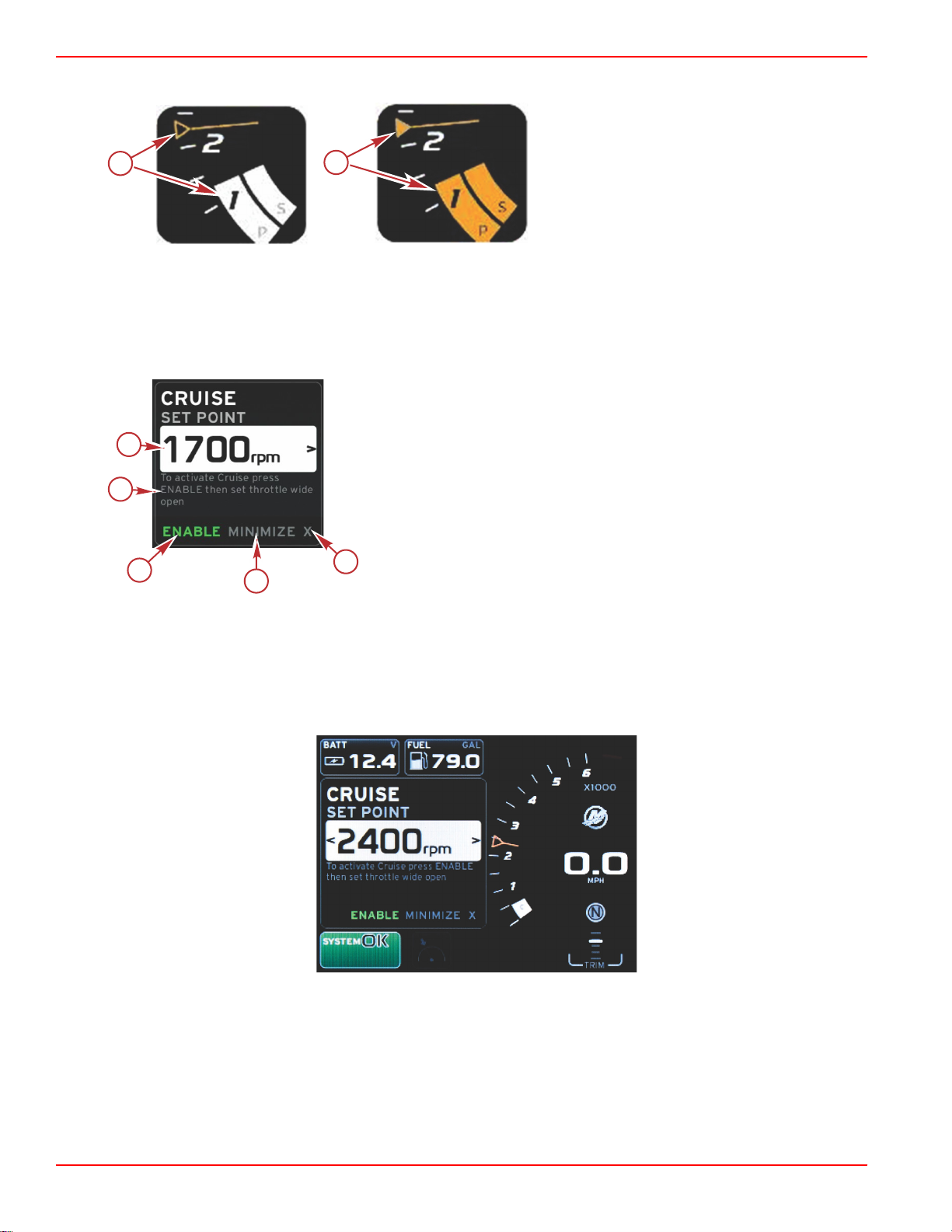
• RPM sweep color will change to orange when active to indicate the engine is computer controlled.
a - Cruise not active
b - Cruise active
Cruise—User-Selected Data Area
Cruise will modify the user‑selected data area of the screen when active.
• Elements within the user‑selected data area will change to allow the user to set‑up:
a. RPM set‑point
b. Cruise status enable or disable
a - Set‑point value
b - Instruction
c - Enable
d - Minimize
e - Exit
Cruise Navigation
Cruise mode will have a modified navigation system similar to Smart Tow. The user‑selected data area footer allows the
operator to enable or disable cruise, minimize, or exit the program element. Footer navigation will follow the same basic
navigation selection strategy as other features.
1. Use the arrow keys to scroll through the selections.
2. Press enter to activate the selection.
Page 38 90-8M0120668 eng MARCH 2016
Page 43

Section 3 - Screen Overview and Operation
60841
60843
60844
a. Enable or disable turns the cruise feature on or off. After selecting enable, place the throttle lever in the wide‑open
forward position and VesselView will control the boat speed.
Enable selected
Disable selected
b. When cruise is disabled, the operator can throttle the boat to any desired speed, and the target marker will remain in
the RPM sweep at the cruise set point.
90-8M0120668 eng MARCH 2016 Page 39
Page 44
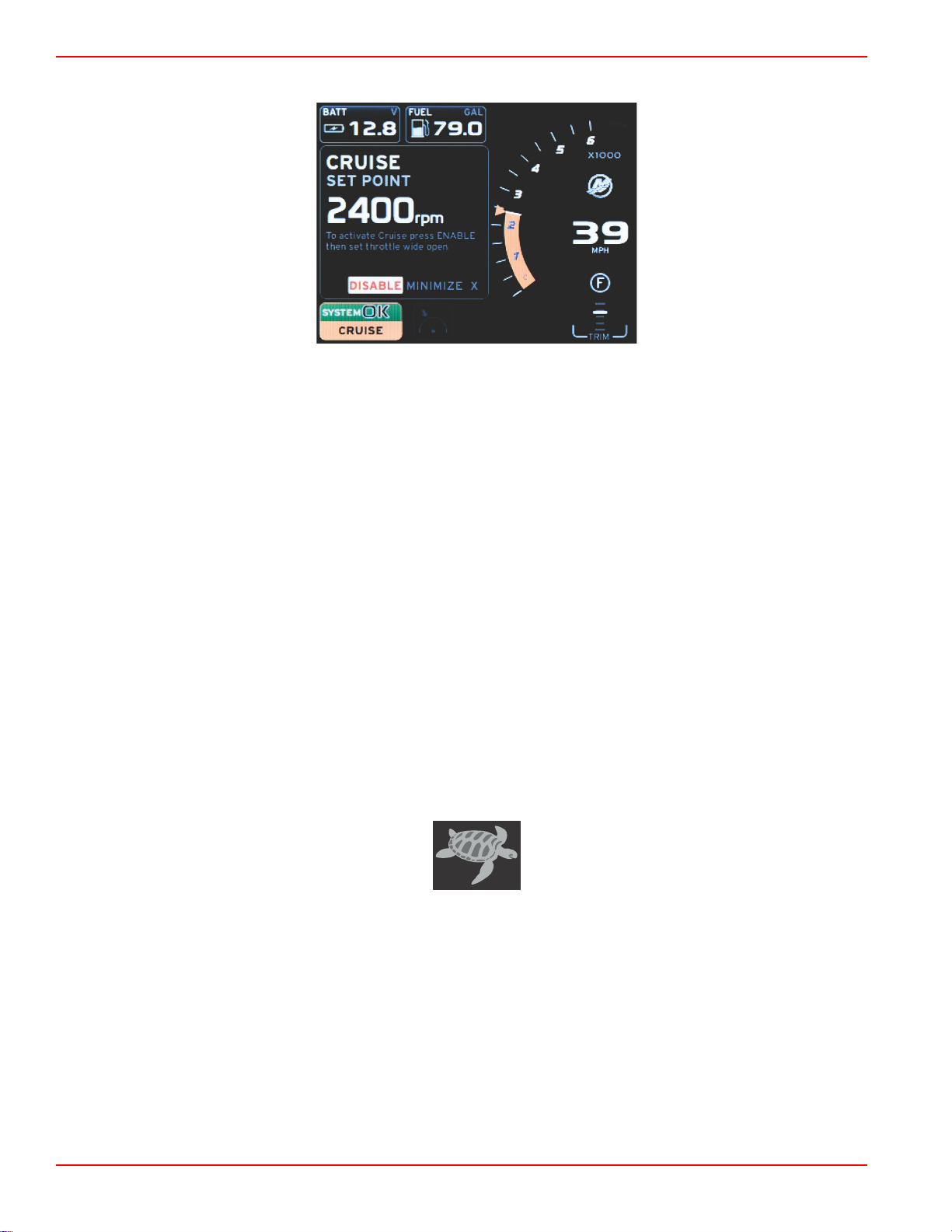
Section 3 - Screen Overview and Operation
60842
57379
c. Selecting enable will return the RPM sweep to the cruise set point.
d. Minimize will hide cruise data and display CRUISE in the system status field. This allows the operator to display
information from other selected icons.
3. The set‑point adjustment selection field will be the default location at cruise start‑up. After the operator makes adjustments
to the desired settings, pressing the PAGES button will move the selection tab to the enable/disable selection in the
user‑selected data area footer.
a. Use the arrow keys to move between the set‑point selections.
b. When the selection tab is outside the navigation area (set‑point field), the operator only needs to change the RPM or
speed adjustments. There is no need to press the enter button to engage the new setting.
4. Minimize is a feature that allows the operator to use the cruise feature while displaying additional data in the user‑selected
data area.
IMPORTANT: Set‑points cannot be adjusted when cruise is minimized.
a. Scroller bar icon selection is limited. Items that are not accessible will be grayed out when cruise is active.
b. If autopilot is active, and cruise is minimized, the system status field will display CRUISE.
• Cruise data will be displayed over autopilot settings if the user selects the system status field.
• If an autopilot pop‑up notification occurs or the operator uses the autopilot CAN trackpad, autopilot data will
automatically fill the user‑selected data area. The operator will have to minimize to hide the pop‑up data.
5. After minimize is activated, the system status field will display CRUISE.
6. When exit is selected while displaying the cruise element and the operator presses enter, the cruise feature will be
disabled. The cruise icon will be displayed next to the system status field until another icon is selected from the scroller bar.
Troll Control Mode
Troll Control
The troll feature allows the operator to select a set‑point and adjust the value so that the vessel maintains a specific speed or
engine RPM.
• Troll is RPM based, unless the vessel incorporated a Mercury Marine GPS into the control area network.
• If the vessel has a Mercury Marine GPS, vessel speed is the default setting.
• The operator can select either RPM set‑points or speed based set‑points. The type of troll option selection can be changed
in the Settings menu.
•
Use the arrow buttons to highlight the troll icon. Refer to Scroller Bar Icons to identify the troll icon.
Page 40 90-8M0120668 eng MARCH 2016
Page 45
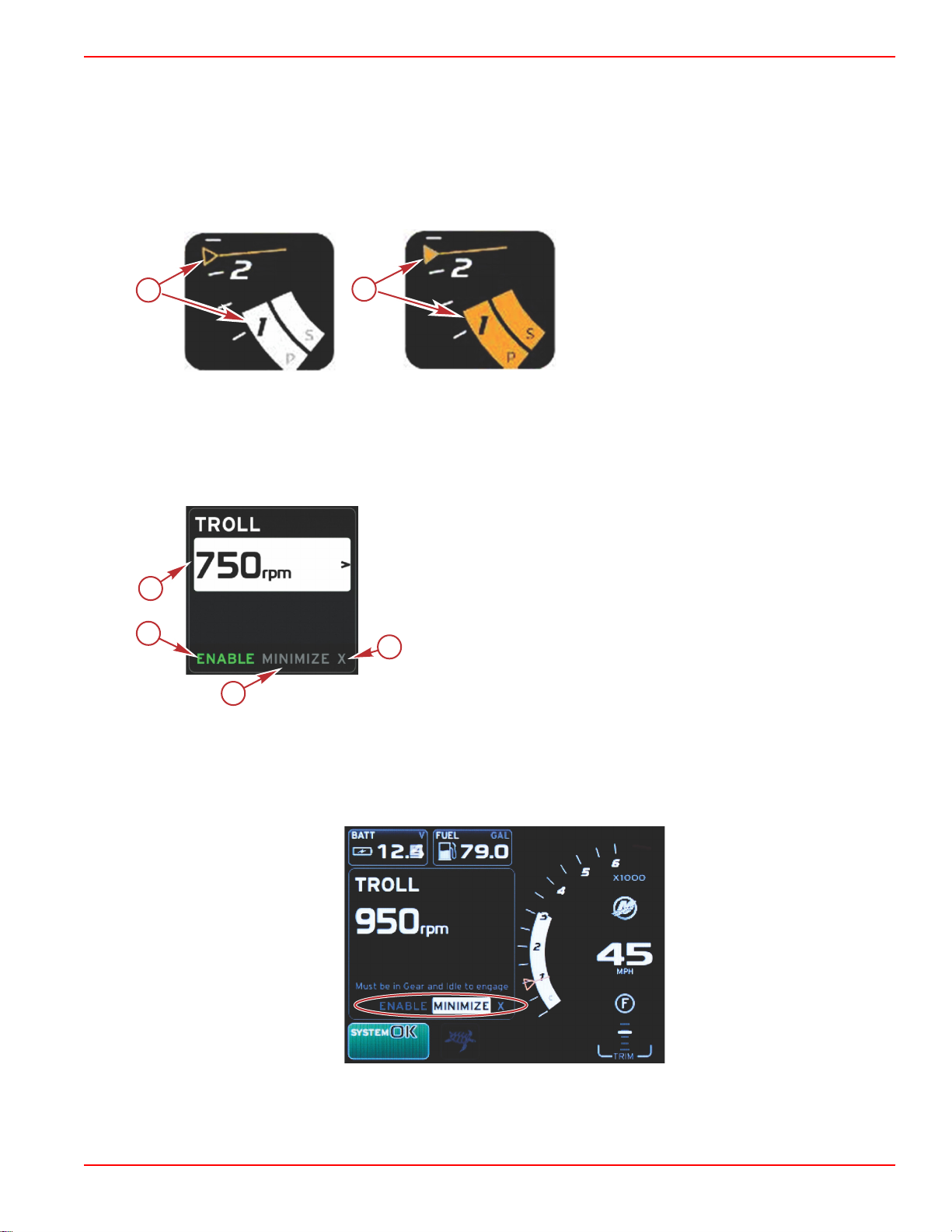
Section 3 - Screen Overview and Operation
60847
a
b
52278
52457
a
b
c
d
Troll Control Data Area
Constant Data Field Change
Troll will modify the constant data field of the screen by incorporating an RPM indicator within the RPM sweep, similar to Smart
Tow and ECO mode targets.
• When troll control mode is activated, elements of the constant data field will be modified to communicate:
• RPM set‑point
• RPM sweep color will change to orange when active to indicate the engine is computer controlled.
a - Not active
b - Active
Troll—User-Selected Data Area
Troll will modify the user‑selected data area of the screen when active.
• Elements within the user‑selected data area will change to allow the user to set‑up:
a. RPM set‑point
b. Troll status enable or disable
a - Set‑point value
b - Enable or disable
c - Minimize
d - Exit
Troll Navigation
Troll mode will have a modified navigation system similar to Smart Tow. The user‑selected data area footer allows the operator
to enable or disable troll, minimize, or exit the program element. Footer navigation will follow the same basic navigation
selection strategy as other features.
1. Use the arrow buttons to go through the selections in the footer.
2. Press enter to activate the selection.
90-8M0120668 eng MARCH 2016 Page 41
Page 46
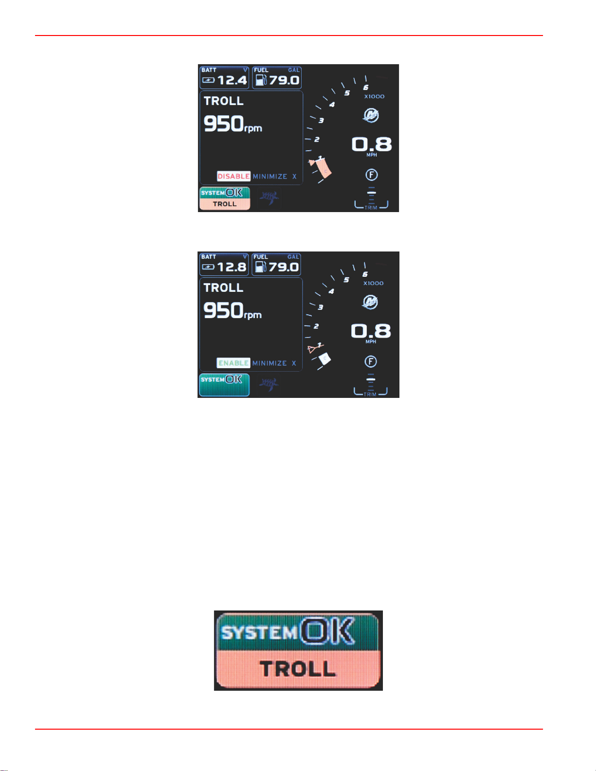
Section 3 - Screen Overview and Operation
60846
60845
60848
a. Enable or disable the element feature.
Enable selected
Disable selected
b. Selecting disable will return throttle control to the operator. Troll cannot be activated again until the throttle is placed
in the idle position while still in gear.
c. Minimize will hide the troll data and display TROLL in the system status field. This allows the operator to display
information from other selected icons.
3. The set‑point adjustment selection field will be the default location at troll start‑up. After the operator makes adjustments to
the desired settings, use the arrow buttons to the enable/disable selection in the user‑selected data area footer.
a. Use the arrow buttons to move between the set‑point selection and the footer.
b. When the selection tab is above the footer navigation area (set‑point field), the operator only needs to use the arrow
buttons to make RPM or speed adjustments. There is no need to press enter to engage the new setting.
4. Minimize is a feature that allows the operator to use the troll feature while displaying additional data in the user‑selected
data area.
IMPORTANT: Set‑points cannot be adjusted when troll is minimized.
a. Scroller bar icon selection is limited. Items that are not accessible will be grayed out when troll is active.
b. If autopilot is active, and troll is minimized, the system status field will display TROLL.
Page 42 90-8M0120668 eng MARCH 2016
Page 47
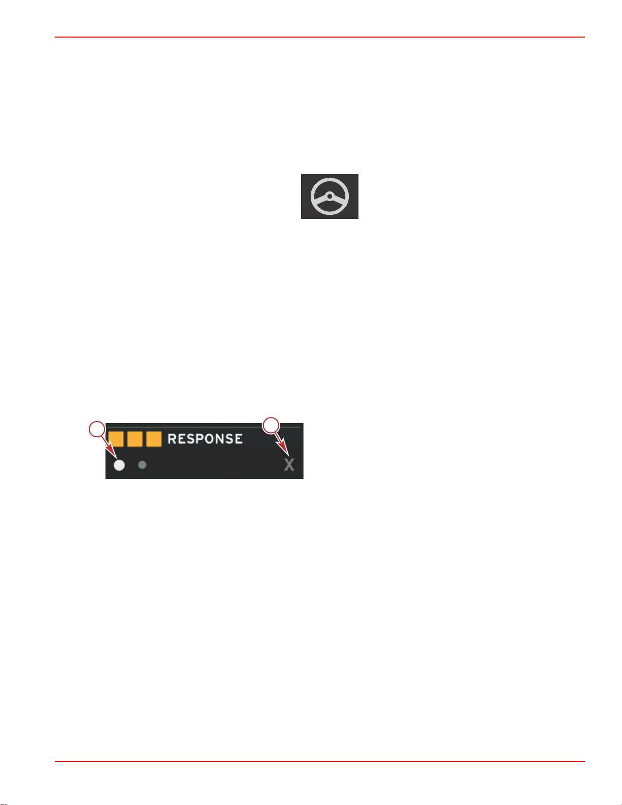
Section 3 - Screen Overview and Operation
57380
a
b
52461
• Troll data will be displayed over autopilot settings if the user selects the system status field.
• If an autopilot pop‑up notification occurs or the operator uses the autopilot CAN trackpad, autopilot data will
automatically fill the user‑selected data area. The operator will have to minimize to hide the pop‑up data.
5. After minimize is activated, the system status field will display TROLL.
6. When exit is selected while displaying troll element, the troll feature will be disabled. The troll icon will be displayed next to
the system status field until another icon is selected from the scroller bar.
Autopilot Screens
Autopilot Screens Overview
VesselView is a display extension for autopilot features and joystick operations. All functionality of these piloting features are
controlled through the Mercury Marine autopilot control area network (CAN) pad. VesselView will show if the mode is active or
in standby; pop‑ups will appear as the vessel arrives at a waypoint asking to acknowledge the turn, and display text on how to
adjust the engine and drives to achieve maximum efficiency.
• Pressing any button on the autopilot CAN trackpad, VesselView will default to displaying the autopilot screen.
• Autopilot will be actively displayed when this feature is turned on. All modes and function are controlled with the CAN pad.
Autopilot Screens Navigation
Autopilot screens will have a modified navigation system. Information will be displayed on two pages of data. Page indicators
and X will be the only selections available.
• Page 1 will contain base autopilot information.
• Page 2 will contain additional navigation data.
• Use the X to hide autopilot data and display the autopilot mode in the system status field. This allows other information to
be displayed in the user‑selected data area.
a - Pages
b - Minimizes autopilot data
Minimize Autopilot
When minimize is selected in the user‑selected data area, autopilot data will be removed. You can select limited items from the
scroller bar for display in the user‑selected data area. The last user‑selected data will be displayed by default.
• Scroller bar selection limited to: Expand, ECO, Fuel Management, Trip Log, Voltage, Navigation, Pressure, Temperature,
Tanks, Cruise, Genset, and Settings.
NOTE: Available scroller bar items are based on the engine selected in the Setup wizard.
• When ECO is active and autopilot is minimized, the system status field will display AUTO.
• Items in the scroll bar that cannot be selected will be gray when Autopilot is active.
• When an autopilot pop‑up occurs, or a button is pressed on the autopilot CAN pad, autopilot data will automatically fill the
user‑selected data area. You must select X to hide the data.
• The system status field will display what mode autopilot is in: track, auto, waypoint sequence, or standby. Waypoint
sequence will display orange in the system status field, all other modes will display gray.
90-8M0120668 eng MARCH 2016 Page 43
Page 48

Section 3 - Screen Overview and Operation
Notes:
Page 44 90-8M0120668 eng MARCH 2016
Page 49

Section 4 - Setup and Calibrations
Table of Contents
Section 4 - Setup and Calibrations
Settings Menu Navigation..................................................... 46
Menu Navigation............................................................ 46
System........................................................................... 46
Language .............................................................. 47
About ..................................................................... 47
Helm 1, Device 1 ................................................... 47
Setup Wizard ......................................................... 47
Restore Defaults .................................................... 48
Network ................................................................. 48
Simulate ................................................................ 48
Time ...................................................................... 48
Vessel............................................................................ 49
Tabs ...................................................................... 50
Tanks ..................................................................... 50
Tank Calibration ............................................. 50
Speed ............................................................. 50
Steering .......................................................... 51
Sea Temp ....................................................... 51
Depth Offset ................................................... 51
Engines.......................................................................... 51
Engines Shown ..................................................... 53
Engine Model ........................................................ 53
Limits ..................................................................... 53
Supported Data ..................................................... 53
ECO Mode ............................................................. 54
Cruise/SmartTow Type .......................................... 54
Trim ....................................................................... 54
EasyLink........................................................................ 54
Engine and Transmission ...................................... 55
RPM Sync ............................................................. 55
Tanks ..................................................................... 56
Preferences................................................................... 56
Buzzer ................................................................... 57
Backlight ................................................................ 57
Scroller Bar ............................................................ 58
Data Boxes ............................................................ 58
Pop‑ups ................................................................. 58
Auto‑Cycle Interval ................................................ 58
Units ...................................................................... 58
Alarms............................................................................59
Personality File.............................................................. 60
Export .................................................................... 61
Import .................................................................... 61
Restore .................................................................. 61
4
90-8M0120668 eng MARCH 2016 Page 45
Page 50
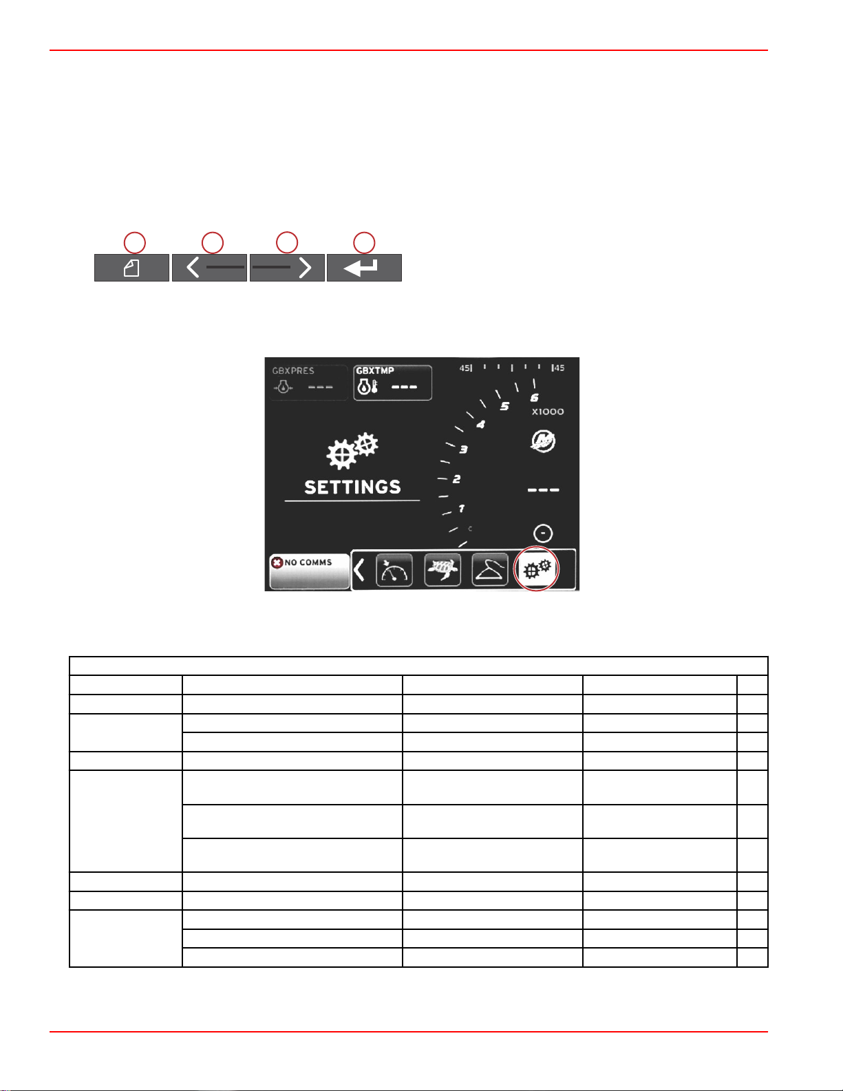
Section 4 - Setup and Calibrations
56815
51606
abc
d
Settings Menu Navigation
Menu Navigation
1. Press the pages button.
2. Press the right arrow button several times until the last icon is highlighted. The last icon is the Settings menu.
3. Press the enter button.
4. Press the left or right arrow buttons to navigate to the pages.
5. Press the enter button to enter the menu.
6. After changing the settings, press the pages button several times to return to the settings icon.
a - Pages button
b - Left arrow button
c - Right arrow button
d - Enter button
System
The following table outlines the navigation of the Settings menu. An asterick (*) indicates that there is an additional selection to
be made at that point in the menu.
System
Language > Select the desired language —
About > Display software version —
Helm 1, Device 1 >
Setup wizard > Next to begin Setup wizard > *
Restore defaults >
Network > Auto Select > Sources > Data Source Selection > *
Simulate > On—checkmark, Off—no checkmark *
Time >
Changes to any of the settings can be made at any time using the Settings menu. All drop‑down and flyout menus can be
navigated by using the LEFT and RIGHT arrow buttons and the ENTER button.
Select helm position > Cancel or Save and Restart
Select device position > Cancel or Save and Restart
All Settings >
Engine Limits >
Alarm History >
Local time offset —
Time Format > 12 hr or 24 hr
Date Format > mm/dd/yyyy or dd/mm/yyyy
Selected—dot, Not selected—
empty
Selected—dot, Not selected—
empty
Selected—dot, Not selected—
empty
Page 46 90-8M0120668 eng MARCH 2016
Page 51

Language
56791
56825
Select the language that will be displayed on VesselView.
1.
With the settings icon highlighted, press the ENTER button. The Settings menu screen will appear.
2.
Press the ENTER button to access the flyout menu of System options and select Language.
Section 4 - Setup and Calibrations
About
View the current software version of VesselView.
Helm 1, Device 1
Set the unique identity of VesselView. This is critical on boats with multiple helms or multiple VesselViews, to ensure proper
data transmission over the network.
Setup Wizard
A convenient and easy to use configuration tool. Setup wizard guides you through the required vessel information selections,
which determine the features and options available to the operator.
• Import configuration from a micro SD card
• Engine setup
• Select engine type
• Select engine model
• Vessel has a joystick, yes/no
• Select number of engines
• Display setup selects which engines will be displayed by VesselView
• Device setup assigns the identification and location of the VesselView
• Units setup selects the units of measure that will be displayed, metric or US standard. Units of measure can be customized
at any time using the Preferences menu.
90-8M0120668 eng MARCH 2016 Page 47
Page 52

Section 4 - Setup and Calibrations
• Tank configuration sets tank type, capacity, and names for vessel tanks
• Speed setup allows selection of the type of device that will send speed data to the VesselView
• Finishing Setup wizard will save all selections and return to the navigation screen
Restore Defaults
Allows the operator to clear all settings, clear alarm history, or clear engine limits.
NOTE: Clearing engine limits has no effect on Engine Guardian protection. Engine limits are set to an operator's preference,
and can be modified or cleared at any time.
Network
Network settings allows the user to select numerous data sources, scan the CAN bus and NMEA backbone for installed data
reporting (input and output) components, and review diagnostic reports—diagnostics shows data on errors and overruns on the
CAN and NMEA communication networks. This can be useful for a skilled technician diagnosing CAN and NMEA
communication errors. Device List shows all CAN bus and NMEA backbone data reporting components that are recognized.
• Auto Select will scan the network and identify any compatible devices.
• Sources allows the operator to select the device which will transmit data to the VesselView. The default selection for each
item is the VesselView.
Data Source Selection
GPS > All data > Auto
Vessel >
Engine > Port and Starboard >
Fuel Tank > Port Fuel and Starboard Fuel >
Fuel Tank > Port and Starboard > Fuel Level and Fuel Remaining
Water Tank > Water > Fresh Water Level
Live Well > Live Well > Live Well Level
Battery > # > Battery Voltage
Speed/Depth > Pitot Speed and Depth > Source
Log/Timer > Water Distance > Calculated
Environment > Outside Temperature > Source
• Device List will display all of the components discovered during the Auto Select process.
• The Diagnostics option displays current activity and load percentage on the CAN networks.
• Magnetic variation can be set to Auto, or the variation can be changed + or – up to 5 digits, including two decimal points.
• Smart Contextual Enabled turns the display of the digital engine RPMs on or off in the user‑selected data area.
• CAN H can be turned off for the purpose of diagnosing communication issues. During normal operation, this feature is
always selected on.
Heading, Vessel fuel rate, Rudder angle, and
Trim tabs >
Temp, Oil Temp, Boost Pressure, Oil
Pressure, Water Pressure, RPM,
Alternator, Fuel Rate, Engine Hours,
Predictive General Maintenance, Trim
Status, Malfunction Indicator Light, Engine
Performance
Simulate
Simulate mode takes VesselView off the network, and generates random data on the screen. Any data shown should not be
regarded as accurate, or be used in the navigation of the boat. Simulate can be used to help the operator become familiar with
VesselView before using it out on the water.
Time
Time settings can be changed through the selection of: Local time, 12/24 hour format, and Date format.
The greater than sign (>) indicates additional menu choices. An asterick (*) indicates additional information on this settings
menu item.
Page 48 90-8M0120668 eng MARCH 2016
Page 53
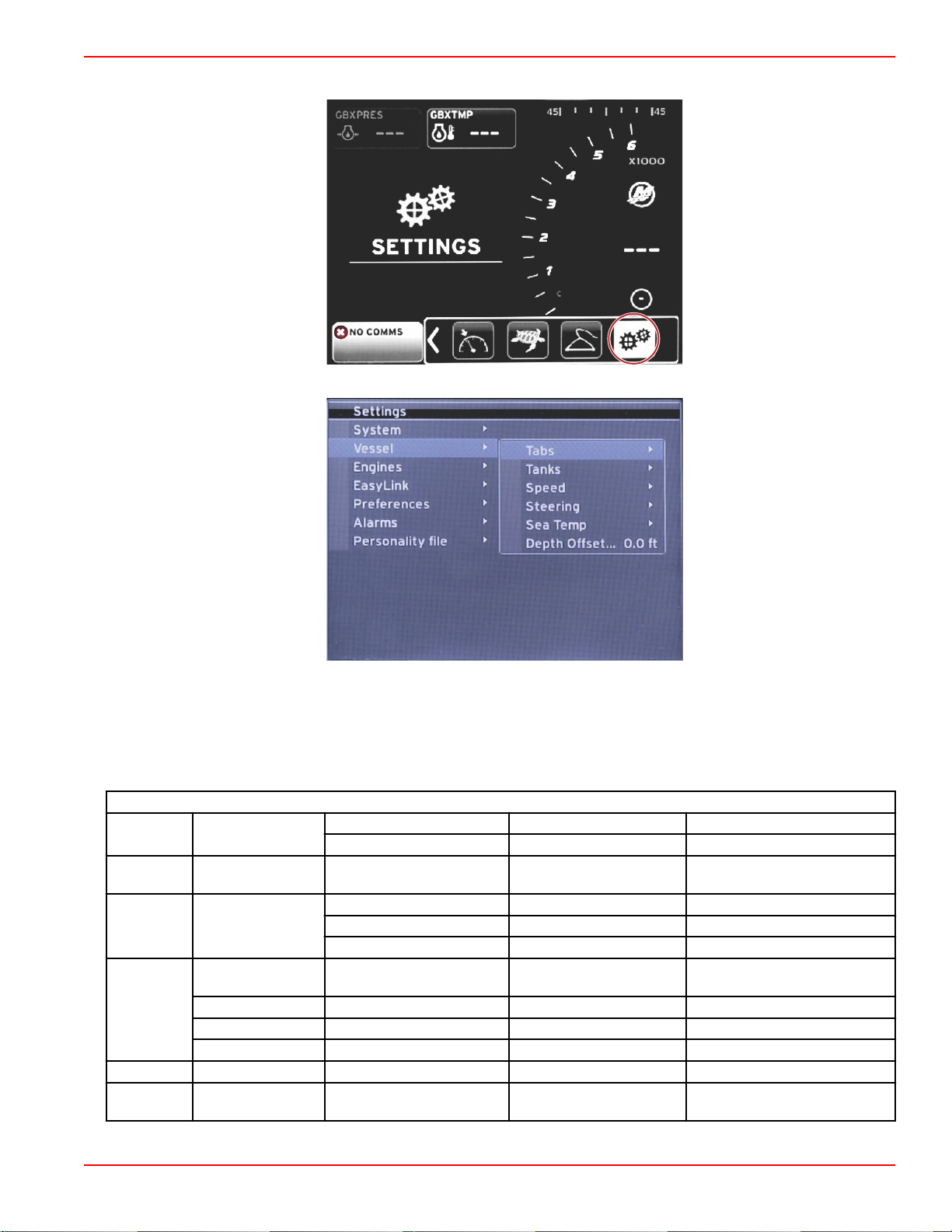
Vessel
56815
56817
Section 4 - Setup and Calibrations
Vessel allows the operator to assign the source of tab data, configure tank names and capacities, determine speed source,
assign the speed and sea temperature, and set the depth transducer offset, source of engines, the number of fuel tanks, and
the total fuel capacity. The fuel capacity can also be reset after refueling.
The greater than sign (>) indicates additional menu choices. An asterick (*) indicates additional information on this settings
menu item.
Vessel
Tabs > Source >
Tanks >
Tank name and
position >
Starboard Calibration > Calibration Window > Reset, Save, or Cancel
Outboard Calibration > Calibration Window > Reset, Save, or Cancel
Calibration > Calibration Window > Reset, Save, or Cancel *
Strategy or GPS > GPS > CAN P or CAN H
Speed > Speed Source >
Pitot > Pitot Source > Sensor Type
Paddle wheel > Paddle wheel Source > Sensor—Current or Legacy
Steering >
Steering Angle
Source >
Show > Dot—display, Empty—hide
Selection
Invert Steering > Dot—yes, Empty—no *
Offset > Offset options > Save or Cancel *
Sea Temp > Selection >
Depth
Offset >
Offset > Offset options > Calibration > Save or Cancel
90-8M0120668 eng MARCH 2016 Page 49
Page 54

Section 4 - Setup and Calibrations
aaa
bbb
c
c
d
60056
a
Tabs
Tabs data source can be selected with this setting. Tab data sources include; tabs, TVMs, and PCMs.
The following are the positions of the Tab source options.
1. PCM0 = starboard outer engine
2. PCM1 = port outer engine
3. PCM2 = center or starboard inner engine
4. PCM3 = port inner engine
5. TVM = pod drive
6. TAB = tab module
The Show option will determine if the tab data is displayed on‑screen, checked = yes, unchecked = no.
Tab calibration allows the operator to put the tabs in their uppermost and lowermost positions and record the percentages. This
is useful for determining the true 0° trim position—the point at which the tabs are parallel with the bottom of the vessel.
Correctly calibrated tabs will show an accurate position of the sliders on the screen.
To calibrate the tabs, trim the tab parallel to the hull, record the reading, this will be the tab's actual 0%. Trim the tab all the way
down, record the reading, this will be the tab's actual 100%. Select SAVE to keep the new calibrated tab data.
Tanks
There are many situations in which a tank may need calibration; odd shaped tanks, V‑bottomed tanks, stepped‑sided tanks,
and even a tank's aspect when the boat is in the water. Floats and senders can send inaccurate data to the operator, causing
problems with fuel and other volume display. The most accurate way to achieve tank calibration is to start with an empty tank
with a known capacity. Pump one quarter of the capacity and record the float or sender position. Repeat this procedure in one
quarter increments, recording the float or sensor position each time, until the tank is full.
Configure Tanks is covered during the Setup wizard process, but changes can be made at any time.
Tank Calibration
Tank calibration allows the operator to adjust the full through empty readings of a tank. When a tank is highlighted, press
ENTER to activate the calibration screen.
The default readings are in the second column, and can be selected by pressing the arrow buttons. In the following example;
we know that the fuel tank is full, but we are receiving a reading of 79 percent full. Select the RECORD button in the 100
percent row, VesselView will now consider a reading of 79 percent as full, and adjust the half and empty readings accordingly.
When the level of a tank is known to the operator, tank calibration can be used to correct the gauge reading to match the
known level at any time.
Speed
Speed source settings are covered during the Setup wizard process, but selection of GPS, pitot, and paddle wheel sources can
be changed with this menu. Strategy and GPS are the options. If the vessel is equipped with a GPS—connected to the CAN
network, choose this option. If the vessel is equipped with a pitot sensor and/or a paddle wheel, this option should be selected.
A speed strategy using pitot sensors and paddle wheels is covered later in this section.
Speed source has the option of choosing a GPS and the GPS source, the CAN P or the CAN H network. A strategy using a
pitot sensor and/or a paddle wheel can also be selected. Selecting the pitot or paddle wheel options brings up a selection of
sources.
Positions of the PCM options is shown in the following illustration.
a - PCM0
b - PCM1
c - PCM2
d - PCM3
The speed‑through‑water (STW) threshold is the approximate transition speed where the calculations from a paddle wheel
switch over to another source—GPS or pitot. The default speed can be changed by selecting the field and using the on‑screen
keypad to enter a new value.
Page 50 90-8M0120668 eng MARCH 2016
Page 55

Section 4 - Setup and Calibrations
56815
32883
b
c
d
a
Steering
Steering source data can be selected to come from either the PCM or the TVM, with options to display the data on‑screen, to
invert steering input, and to establish a steering offset degree.
The Invert steering option is helpful when there is a VesselView which is rear‑facing. In this case the steering data will match
the operator's point of view.
Steering Offset is used to align the outboard, sterndrive or inboard to 0°. When the drive is positioned perpendicular to the hull,
the steering angle may not match the steering sensor on the drive. To adjust this variance, select the Offset tab. The Steering
Angle Calibration box appears. Selecting the Calibrated row Zero button will apply the offset. Note that the offset does not
change on the display indicator until the SAVE button is selected.
Sea Temp
Depending on the type of water temperature sender the vessel has, the operator can select the source of the data. PCM
options are for vessels equipped with a SmartCraft sensor. The Airmar® options are for vessels equipped with the sensor
hooked up to the 4‑pin diagnostic connection on the engine. The chart shows the position of the engine that is being used to
transmit temperature data to the VesselView.
SmartCraft sensor
PCM0 Starboard outer engine Airmar0 Starboard outer engine
PCM1 Port outer engine Airmar1 Port outer engine
PCM2 Starboard inner engine or center Airmar2 Starboard inner engine
PCM3 Port inner engine Airmar3 Port inner engine
Depth Offset
Depth Offset is the distance from the tranducer to the actual waterline. The offset default setting is 0.0 ft. To set an offset below
the transducer, subtract from the depth offset. To set an offset above the transducer, add to the depth offset.
Airmar sensor
a - Depth transducer
b - To set an offset below the
transducer, subtract from the depth
offset
c - No offset. Distance from depth
transducer to bottom.
d - To set an offset above the
transducer, add to the depth offset
Engines
90-8M0120668 eng MARCH 2016 Page 51
Page 56

Section 4 - Setup and Calibrations
56818
Engines allows the setting of the engine type and model. Engine limits can be set using minimum and maximum values for
operating parameters. Selection of supported data items can be turned on or off from this menu. ECO, Cruise, Smart Tow, and
trim settings are adjusted through the Engines menu Settings.
The greater than sign (>) indicates additional menu choices.
Engines
Port, dot—yes, empty—no
Engines shown > Select >
Engine model > Select
RPM >
Fuel Rate > STBD or PORT >
Coolant Temp >
Oil Temp >
Oil Pressure >
Limits >
Water Pressure >
Battery Voltage >
Intake Temp > STBD or PORT >
Boost Pressure > STBD or PORT >
Trans Oil Pressure > STBD or PORT >
Trans Oil
Temperature >
Starboard, dot—yes, empty
—no
Min, Max, and Warnings
Options >
Min, Max, and Warnings
Options >
Min, Max, and Warnings
Options >
Min, Max, and Warnings
Options >
Min, Max, and Warnings
Options >
Min, Max, and Warnings
Options >
STBD or PORT >
Reset, Save, or Cancel
Min, Max, and Warnings
Options >
Reset, Save, or Cancel
Reset, Save, or Cancel
Reset, Save, or Cancel
Reset, Save, or Cancel
Min, Max, and Warnings
Options >
Min, Max, and Warnings
Options >
Min, Max, and Warnings
Options >
Min, Max, and Warnings
Options >
Reset, Save, or Cancel
Reset, Save, or Cancel
Reset, Save, or Cancel
Reset, Save, or Cancel
Reset, Save, or Cancel
Page 52 90-8M0120668 eng MARCH 2016
Page 57
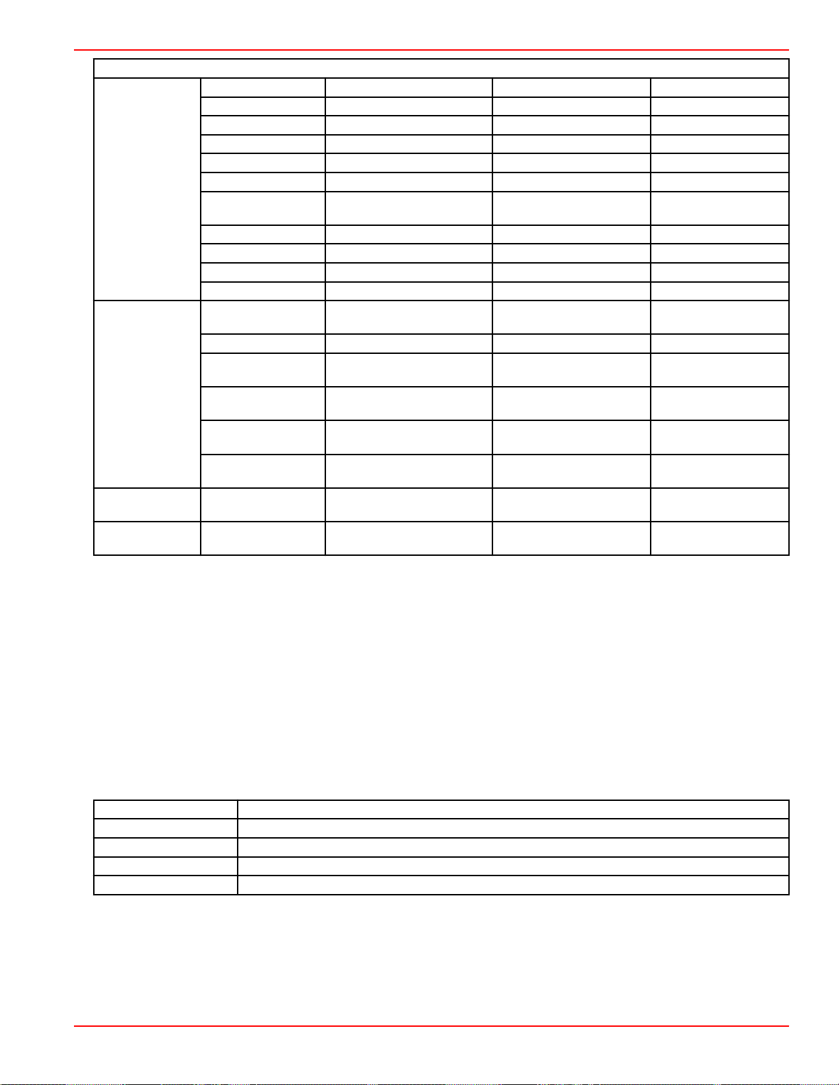
Supported Data >
ECO Mode >
Cruise/SmartTow
Type >
Trim >
Engines
Actual Gear > Dot—yes, empty—no
Boost Pressure > Dot—yes, empty—no
Fuel Pressure > Dot—yes, empty—no
Gear Pressure > Dot—yes, empty—no
Gear Temperature > Dot—yes, empty—no
Load Percent > Dot—yes, empty—no
Manifold
Temperature >
Oil Pressure > Dot—yes, empty—no
Oil Temperature > Dot—yes, empty—no
Throttle Percent > Dot—yes, empty—no
Water Pressure > Dot—yes, empty—no
Fuel Economy
Stability >
RPM Stability > Enter Data
RPM Window
Minimum >
RPM Window
Maximum >
RPM Target
Proximity >
Trim Target
Proximity >
RPM—Auto, RPM,
or Speed
Show—PORT and
STBD >
Dot—yes, empty—no
Enter Data
Enter Data
Enter Data
Enter Data
Enter Data
Has Trim—dot—yes, empty
—no
Section 4 - Setup and Calibrations
Calibration Data > Reset, Save, or Cancel
Engines Shown
Engines shown is covered during the Setup wizard process, but display options can be changed in the Engines menu settings
at any time. VesselView can display up to two engines, depending on the number of engines chosen during the Setup wizard
process. The operator can select which engines are displayed. Checking or unchecking the engine selection will determine
which engines are displayed on the VesselView.
Engine Model
Engine model settings allows the user to change power package descriptions. Engine model is covered during the Setup
wizard, but changes can be made anytime. Any changes made here may make other settings and display options unavailable
in VesselView. Use the rotary knob to help scroll through the list of engines, press the rotary knob to make a selection.
Limits
Limits helps set specific ranges for many engine data parameters, such as; RPM, coolant temperature, oil temperature, battery
voltage, and boost pressure. Changes made to limits will not affect the engine package or the operation of Mercury's Engine
Guardian programming. The actual engine limits are determined by the factory programmed control module on the engine.
Setting
Min: The value of the base of the on‑screen graph
Max: The value of the top of the on‑screen graph
Warning low: The value at the top of the lower red color section of the on‑screen graph
Warning high: The value at the bottom of the upper red color section of the on‑screen graph
Description
Supported Data
Supported Data settings allows the operator to select which engine and drive information is displayed on the screen. Data
boxes are preselected based on the engine model selected, but can be changed at any time. Supported data varies from
engine to engine.
90-8M0120668 eng MARCH 2016 Page 53
Page 58

Section 4 - Setup and Calibrations
56815
56819
ECO Mode
ECO Mode settings allow the adjustment of the fuel economy and RPM display refresh intervals, adjustment of the desired
RPM range, and the accuracy of the RPM and trim targets. Defaults are based on the engine model selected in the Engine
model selection menu. See Section 3 ‑ ECO Mode for additional information.
Cruise/SmartTow Type
Cruise/SmartTow type settings lets the operator select the source from which VesselView receives speed data—GPS, RPM, or
Auto. The default selection is auto. VesselView monitors data from the speed source selection entered during the Setup wizard.
Trim
Trim settings allows the operator to select which engine's or drive's trim position is displayed on the VesselView screen. When
trim is unchecked in the Settings menu, the onscreen trim display is replaced with an additional data box.
Trim settings also allows calibration of a drive or engine's trim display range. VesselView shows a graduated scale in the
user‑selected data box as well as a graduated slider on the bottom of the screen. Trim percentages are represented by the
lighter gray marks. Tilt is represented by the darker marks. The white bar on the graph indicates the actual trim position.
Using the calibration window, trim percentages can be fine‑tuned to better display actual limits on‑screen in the trim status
fields.
The point at which the trim range and the tilt range meet is the point where trim becomes tilt. This transition percentage point
can be adjusted to more accurately reflect the position of the slider bar in the trim scale display.
EasyLink
Vessels with SC 100 gauges must have the easy links enabled (dot) in VesselView for data to be received at the SC 100
gauge.
Page 54 90-8M0120668 eng MARCH 2016
Page 59

Section 4 - Setup and Calibrations
59954
60226
EasyLink
Engine and Transmission > Port or Starboard—On—dot, off—no dot
RPM sync > Port or Starboard—On—dot, off—no dot
Fuel tank 1 > Port or Starboard—On—dot, off—no dot
Port, Starboard >
EasyLink settings allow the link gauge connectors on the VesselView harness to be used to transmit data to link gauges at the
helm. Four link gauge connections on the VesselView harness are labeled; SYS LINK STBD and SYS LINK PORT.
The port and starboard link connectors can be chosen to transmit data that comes from sources that are not the same as the
link harness label. This can be helpful when similar gauges are located beyond the length of the link gauge female gauge
extension harness.
Fuel tank 2 > On—dot, off—no dot
Oil tank > On—dot, off—no dot
Fresh Water > On—dot, off—no dot
Wastewater tank > Gray tank 1, Black tank 1—On—dot, off—no dot
Example of EasyLink connectors on a VesselView harness
Engine and Transmission
Engine and transmission data can be selected to display on a compatible link gauge by selecting the harness connection that
will be used to transmit the data.
RPM Sync
RPM synchronization brings multiple engines to the same RPM level utilizing the SYNC button on the CAN trackpad. If the
vessel has a SYNC link gauge, the operator can see the needle move until SYNC is achieved. The default position of the link
harness connection is PORT for this gauge, PORT should always remain checked.
90-8M0120668 eng MARCH 2016 Page 55
Page 60
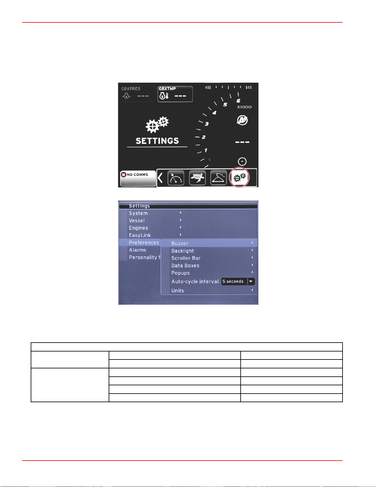
Section 4 - Setup and Calibrations
56815
56820
Tanks
During tank setup, information was entered that defined the location, name, and capacity of individual tanks. Link gauge
settings allow the operator to select which link harness will transmit data from the tank tab selected. Tank tabs with an
arrowhead indicate that tank was defined during tank setup in the Vessel Settings menu, and can be assigned an EasyLink
location.
Preferences
The Preferences menu allows the operator to set beep levels, change backlighting settings, activate scroller bar items,
populate data boxes, customize pop‑up screens, and choose units of measure.
The greater than sign (>) indicates additional menu choices.
Preferences
Buzzer >
Backlight >
Page 56 90-8M0120668 eng MARCH 2016
Key beeps—Off, Quiet, Normal, or Loud —
Alarm beeps—On—dot, off—no dot —
Level > Select 0%—100%
Night mode > On—dot, Off—no dot
Network update > On—dot, Off—no dot
Local gain > Input 0%—100%
Page 61

Section 4 - Setup and Calibrations
Preferences
Auto‑hide delay > Select 5, 10, 15, or 20 seconds
X‑Pand—On—dot, Off—no dot
Temperatures—On—dot, Off—no dot
Pressure—On—dot, Off—no dot
Voltages—On—dot, Off—no dot
Fuel—On—dot, Off—no dot
Tanks—On—dot, Off—no dot
Advanced—On—dot, Off—no dot
Scroller Bar >
Data Boxes >
Pop‑ups >
Auto‑cycle interval > Select 1, 5, or 10 seconds —
Units >
Item visibility >
NOTE: Available data boxes are power‑package
dependent. Select the options you want displayed.
Warnings > On—dot, off—no dot
Joystick Piloting > On—dot, off—no dot
Trim > On—dot, off—no dot
Trim pop‑up time > Select 2, 5, or 10 seconds
Distance—nm, km, or mi —
Distance small—ft, m, or yd —
Speed—kn, kph, or mph —
Wind speed—kn, kph, mph, or m/s —
Depth—m, ft, or fa —
Altitude—m or ft —
Heading—°M or °T —
Temperature—°C or °F —
Volume—L or gal —
Economy—Distance/Volume, Volume/Distance,
mpg, g/mi, km/L, or L/100km
Pressure—in. Hg, bar, psi, or kPa —
Baro Pressure—in. Hg, mb, or hPa —
Performance—On—dot, Off—no dot
Trim and Tabs—On—dot, Off—no dot
Trip Log—On–On—dot, Off—no dot
Navigation—On—dot, Off—no dot
Generator—On—dot, Off—no dot
ECO—On—dot, Off—no dot
Autopilot—On—dot, Off—no dot
Cruise—On—dot, Off—no dot
Troll Control—On—dot, Off—no dot
SmartTow—On—dot, Off—no dot
—
—
Buzzer
Buzzer setting allows the user to set the volume level for key touch beeps. The beep is an auditory acknowledgement that a
selection has been made.
Alarm beeps can be turned on or off from this tab. All alarms will be displayed on the VesselView screen regardless of the
alarm beep status. Alarm beep preferences only apply to alarms that are not driven by the Mercury Guardian system. For
example, low fuel level.
Backlight
Backlight preferences can be set with this menu.
• The light level of the display can be changed in ten percent increments from 10 to 100 percent.
• Night mode is available for better low light or dark viewing.
90-8M0120668 eng MARCH 2016 Page 57
Page 62

Section 4 - Setup and Calibrations
• Network update will display all link gauges and devices connected to the VesselView at the same level percentage as the
operator selects in the Level tab.
• Local gain can only be used to adjust the VesselView display independent of other displays and gauges, even if the
Network update box is checked. In some lighting conditions, the VesselView display may be too bright for comfortable
viewing, but other displays and gauges may need to maintain their level of brightness. Follow these instructions to apply
Local gain to the VesselView display:
a. Select Level and choose a percentage of brightness.
b.
Select Local gain and input the percentage chosen in step a, on the keypad, select OK.
c.
Return the Level option to 100%. The VesselView display will remain dimmed while all networked devices and
gauges will maintain their brightness.
d.
To return the VesselView to full brightness, select Local gain and input 100 and select OK.
e.
Select the Level tab and choose any percentage other than 100 and press Enter. Select 100% and the unit will return
to 100% brightness.
Scroller Bar
Scroller Bar settings offers an auto‑hide delay of five to thirty seconds before it is minimized if no selection is made.
Scroller Bar Item visibility displays the checked items to appear in the scroller bar menu at the bottom of the VesselView
screen. Scroller Bar items are preselected based on the engine selection during the Setup wizard, but any Scroller Bar items
can be checked on or off at any time.
Data Boxes
Data Boxes display up to three items of data on the screen.
The number of data boxes can be increased from one up to three, depending on selections made in the Settings menu. When
one data box is displayed it appears in the upper left of the screen. If the option for additional data boxes is grayed out, then all
available space is currently being used by the VesselView. To free up space on the screen, use the following directions.
To activate a second data box, enter the Settings menu. Select Vessel>Tabs>Show. Uncheck the Show option to remove the
Tabs data from the screen. This area of the screen will be replaced by the second data box.
To activate the third data box, enter the Settings menu. Select Engines>Trim>Show. Uncheck the Show option to remove the
Trim data from the screen. This area of the screen will be replaced by the third data box.
NOTE: The Fuel Used data box cannot have the value reset. Fuel Used, shown as FULUSD, is a value that will continue to
increase throughout the life of the display. Only a Master Reset will clear the Fuel Used data value. In place of showing the
Fuel Used data box, select the Fuel Used Trip data box. The reset procedure can be found in the Trip Log icon in the Scroller
Bar. Selecting RESET in the user‑selected data area will clear any value on the display. Fuel Used Trip, shown as FULTRP,
can be reset as often as desired using this procedure.
Pop-ups
Pop‑ups allows the operator to select the types of pop‑ups that will appear on the screen. Choice of pop‑ups include; warnings,
Joystick Piloting, and trim information.
Joystick Piloting alerts will appear in the system status tray at the bottom of the screen, to inform the operator that an autopilot
feature is engaged.
The Warnings checkbox allows the operator to have any engine faults displayed full size in the user‑selected data area when
checked. Unchecked, the fault will appear in the system status field in the lower left of the screen.
Auto-Cycle Interval
Auto‑cycle interval determines the duration that data in the user‑selected data field is displayed, options are 1, 5, or 10
seconds.
Units
Units of measure can be independently selected. The operator can choose from U.S. standard, metric, or nautical.
Page 58 90-8M0120668 eng MARCH 2016
Page 63

Alarms
56815
56821
Section 4 - Setup and Calibrations
Alarms allows you to check the history for any alarm, turn a specific alarm on or off, or show all the alarms. Use the arrow
buttons to highlight the option and press the enter button to enable or disable the alarm.
90-8M0120668 eng MARCH 2016 Page 59
Page 64

Section 4 - Setup and Calibrations
56815
Alarm History
Alarms >
Alarm Settings >
Show all Helm
alarms
Alarms
Shows legacy alarms
NOTE: These settings must be enabled to
receive alarms.
Shallow water—On—dot, Off—no dot
Deep water—On—dot, Off—no dot
Speed through water rationality fault—On—
dot, Off—no dot
Fuel remaining low—On—dot, Off—no dot
Fuel Tanks >
Oil tanks >
Fresh water tanks >
Gray water tanks >
Black water tanks >
Live well water tanks >
On—dot, Off—no dot
NOTE: See text following table.
PORT FUEL low—On—dot, Off—no dot
PORT FUEL high—On—dot, Off—no dot
STBD FUEL low—On—dot, Off—no dot
STBD FUEL high—On—dot, Off—no dot
Oil low—On—dot, Off—no dot
Oil high—On—dot, Off—no dot
Fresh water low—On—dot, Off—no dot
Fresh water high—On—dot, Off—no dot
Gray water low—On—dot, Off—no dot
Gray water high—On—dot, Off—no dot
Black water low—On—dot, Off—no dot
Black water high—On—dot, Off—no dot
Live well low—On—dot, Off—no dot
Live well high—On—dot, Off—no dot
When in Alarm History, press and hold the PAGES button. A pop‑up window will appear with the option to clear all faults.
Select it and the history will be cleared. Alarm history and data cannot be saved or transferred from the VesselView unit.
Alarm Settings allows the operator to select and change the parameters—minimums and maximums, as to when an alarm will
sound.
The Show all Helm alarms checkbox can be turned on—dot, or off—no dot.
Personality File
Page 60 90-8M0120668 eng MARCH 2016
Page 65
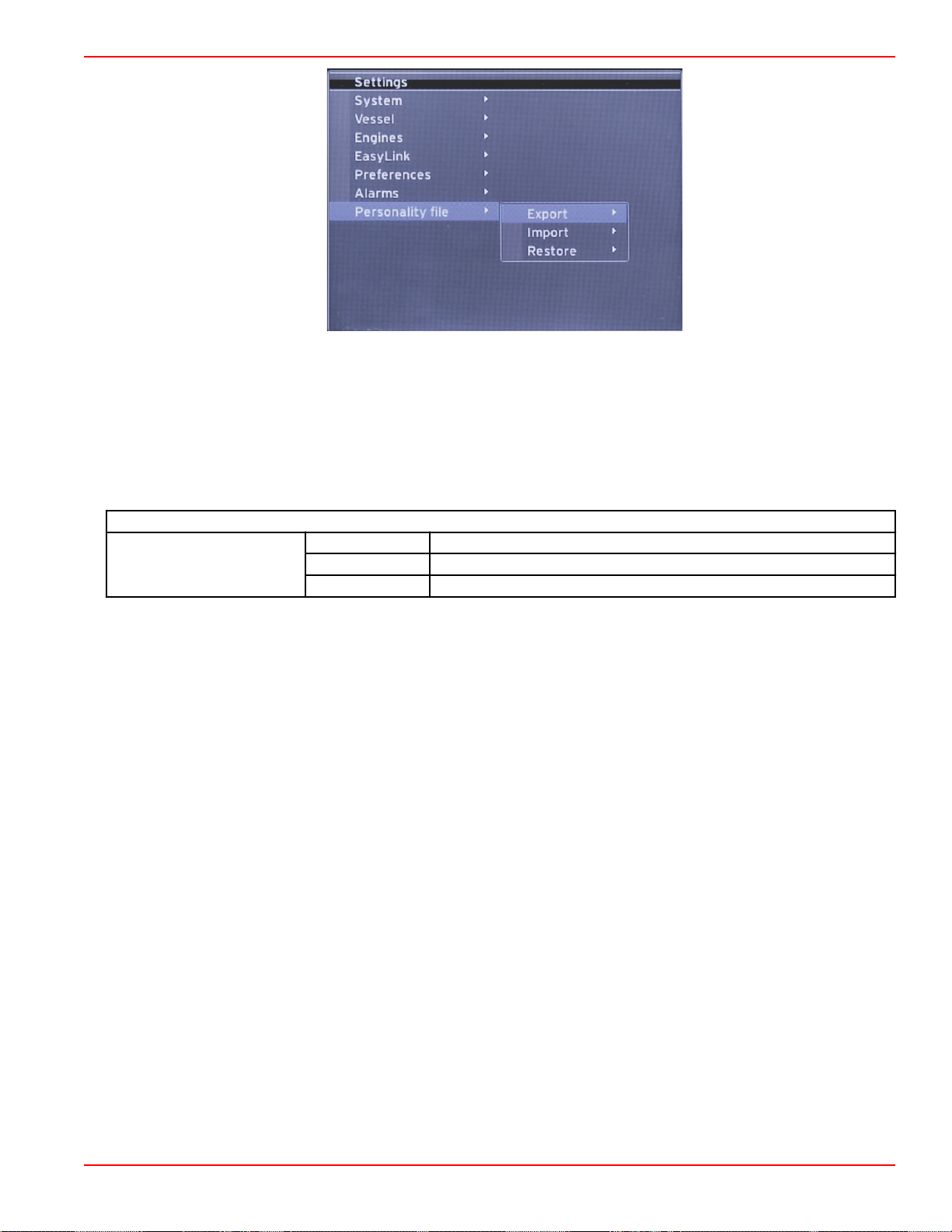
Section 4 - Setup and Calibrations
56822
Within the Personality Settings menu, operators can Export or Import a vessel personality. Vessel personalities are files used
by boatbuilders and boat owners to set all of the preferences and settings in VesselView, to optimize the systems onboard. The
micro SD card port is used to transfer files to and from the VesselView. Importable personalities will be detected by VesselView
from the micro SD card, and the operator will be able to scroll through the list and select the appropriate personality. To export
a personality file, the micro SD card must be inserted into the VesselView.
The restore option can only be used by trained installers to restore OEM settings. A VesselView that is configured by a
boatbuilder or dealer, contains a file that is specific to the vessel, and can be used to bring the unit back to its configured
settings. Contact an authorized dealer, if this option is needed.
Personality File
Export > To new file...
Personality file >
Import > Suitable file must be on SD card
Restore >
NOTE: Only used by a trained technician.
Export
Exporting the personality file from the VesselView is done by selecting the Export option. A window will appear asking to export
the personality. This will create a file which contains all of the settings and preferences of the VesselView. This file can be
imported, in the future, to return the VesselView back to the current personality.
Import
To import a personality file, verify the SD card is inserted into the VesselView. Select Import and choose from the displayed
personalities. All personalities on the SD card must be on the root level, and not in any folders. Importing a personality file can
also be done during the Setup wizard process.
Restore
The restore option can only be used by trained installers to restore OEM settings. A VesselView that is configured by a
boatbuilder or dealer contains a file that is specific to the vessel, and can be used to bring the unit back to its configured
settings. Contact an authorized dealer, if this option is needed.
90-8M0120668 eng MARCH 2016 Page 61
Page 66

Section 4 - Setup and Calibrations
Notes:
Page 62 90-8M0120668 eng MARCH 2016
Page 67

Table of Contents
Section 5 - Warning Alarms
Section 5 - Warning Alarms
Warnings—Faults and Alarms ............................................. 64
Fuel Critical Alarm......................................................... 64
Depth Alarm................................................................... 64
5
90-8M0120668 eng MARCH 2016 Page 63
Page 68

Section 5 - Warning Alarms
52101
51619
abcde
Warnings—Faults and Alarms
All Mercury warnings—faults and alarms will be shown regardless of what screen is displayed at the time of the alarm. When
an alarm is activated, the system status field will display the alarm text and icon. Faults, along with their descriptive short text,
long text, and action text, will be displayed full screen.
• When a fault occurs:
a. The system status field will turn red and show the warning icon and text.
b.
Fuel and depth faults will have additional options and will be described in Fuel Critical Alarm and Depth Alarm.
c. A level 3 fault—trim, navigation, ECO, fuel, can be turned off or on by the operator in the Settings menu. By default it
is turned on. If the fault is turned off in the Settings menu, the faults will only show in the system status field.
d. All level 4—Guardian faults, will always be displayed regardless of what is selected in the Settings menu.
e. If the fault is related to emissions control, the engine icon will be displayed in the system status field.
• When the operator selects a fault in the user‑selected data area:
a. The fault title with the warning icon will be displayed at the top.
b. Short text fault description and the fault location—engine, will be displayed below the title.
c. When more than one fault exists, press the PAGES button to access the faults. Use the arrow keys to navigate to
each fault.
a - Fault title with warning icon
b - Short text or legacy text
c - Engine fault location
d - Action text
e - Number of faults
Fuel Critical Alarm
The fuel alarm is managed by VesselView, through the Settings>Alarms>AlarmSettings>, not by the engine ECM/PCM.
• Notification properties and fuel level alarms can be set in the Settings menu.
•
If the operator has fuel selected as a constant data field in location #2—refer to Screen Display Locations and
Descriptions, then the fuel data field will show the warning.
• The warning icon will replace the fuel icon and the data field will remain red.
• If the operator does not have fuel displayed as a constant data field in location #2, but it is active as a warning fault, then
the system status field will display a red field and show FUEL.
• The operator can also select the fuel warning as a user‑selected data area pop‑up in the Settings menu. Selecting the X
will minimize the fuel level alarm. The fault will still be displayed in one of two locations, depending on the screen set‑up.
Depth Alarm
The depth alarm is managed by VesselView, through the Settings>Alarms>AlarmSettings>, not by the engine ECM/PCM.
• Notification properties and depth warning levels can be set in the Settings menu.
•
If the operator has depth displayed as a constant data field in location #1—refer to Screen Display Locations and
Descriptions, then the depth data field will show the warning.
Page 64 90-8M0120668 eng MARCH 2016
Page 69

Section 5 - Warning Alarms
• The warning icon will replace the depth icon and the data field will remain red.
• If the operator does not have depth displayed as a constant data field in location #1, but it is active as a warning fault, then
the system status field will display a red field and show DEPTH.
• The operator can also show the depth warning as a user‑selected data area pop‑up in the Settings menu. Selecting the X
will minimize the depth alarm. The fault will still be displayed in one of two locations depending on the screen set‑up.
90-8M0120668 eng MARCH 2016 Page 65
 Loading...