

Page 1

Gasoline Engines - Alpha Models
1998, Mercury Marine 90860168985 1098
Page 2

0
CB751
Identification Record
PLEASE RECORD THE FOLLOWING INFORMATION:
1.
Engine Model and
Horsepower
Engine Serial
Number
2.
Transom Assembly Serial
Number (Sterndrive)
Gear
Ratio
Sterndrive Unit
Serial Number
3.
Transmission Model
(Inboard)
Gear
Ratio
Transmission
Serial Number
4.
Propeller Number
Pitch Diameter
5.
Hull Identification Number
(HIN)
Purchase
Date
6.
Boat Manufacturer
Boat
Model
Length
7.
Exhaust Gas Emissions Certificate Number (Europe Only)
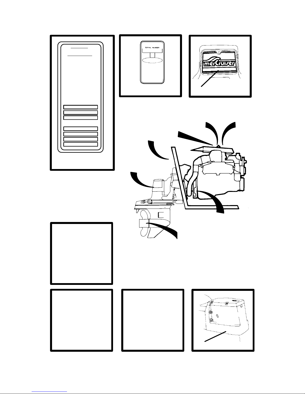
SERIAL NUMBERS
The serial numbers are the manufacturer’s keys to numerous engineering details
which apply to your MerCruiser power package. When contacting your Authorized
MerCruiser Dealer about service, always specify model and serial numbers.
The description and specifications contained herein were in effect at the time this
guide was approved for printing. Mercury Marine, whose policy is one of continuous
improvement, reserves the right to discontinue models at any time, or to change
specifications or designs, without notice and without incurring obligation.
Mercury Marine, Fond du Lac, Wisconsin, U.S.A. Printed in U.S.A.
1998, Mercury Marine
The following are registered trademarks of Brunswick Corporation: AutoBlend, Jet-Prop,
Mariner, Merc, MerCathode, MerCruiser, Mercury, Mercury Marine, Quicksilver, RideGuide,
and Thruster.
Page 3
1
CA469
71352
ABC12345Z123
-19 48-12345
71345
4
5
1
2
2,7
7
2
1
44
5
74677
1,2
COLOR CODE
MERCRUISER
Division of Mercury Marine
Stillwater, OK, U.S.A.
SPECIFICATIONS
MODEL MCM 4.3LX/4.3LXH GEN +.
DISPLACEMENT 262 CID. . . . . . . . .
IGNITION TIMING 10 BTDC. . . . . . .
CYL. FIRING ORDER 1-6-5-4-3-2. . .
SPARK PLUGS AC-MR43LTS. . . . .
ENGINE ROTATION LH. . . . . . . . . . .
MAX W.O.T. RPM 4400-4800. . . . . .
IDLE RPM IN NEUTRAL 650. . . . . . .
PLUG GAP .045’. . . . . . . . . . . . . . . . .
For Fuel and Oilrequirements refer to
Operations & Maintenance Manual
SERIAL NUMBERS
2
71718
74849
2
Page 4

2
TABLE OF CONTENTS
Page
Welcome! 4. . . . . . . . . . . . . . . . . . . . . . . . . . . . . . . . . . . . . . . . . . . . . . .
Warranty Message 4. . . . . . . . . . . . . . . . . . . . . . . . . . . . . . . . . . . . .
Read This Manual Thoroughly 5. . . . . . . . . . . . . . . . . . . . . . . . . . .
General Information 6. . . . . . . . . . . . . . . . . . . . . . . . . . . . . . . . . . . . .
Lanyard Stop Switch 6. . . . . . . . . . . . . . . . . . . . . . . . . . . . . . . . . . .
Exhaust Emissions 9. . . . . . . . . . . . . . . . . . . . . . . . . . . . . . . . . . . . . .
Be Alert To Carbon Monoxide Poisoning 9. . . . . . . . . . . . . . . . . .
Safe Boating Suggestions 12. . . . . . . . . . . . . . . . . . . . . . . . . . . . . .
Protecting People In The Water 15. . . . . . . . . . . . . . . . . . . . . . . . .
While You Are Cruising 15. . . . . . . . . . . . . . . . . . . . . . . . . . . . . . . .
While Boat Is Stationary 15. . . . . . . . . . . . . . . . . . . . . . . . . . . . . . .
High-Speed And High-Performance Boat Operation 15. . . . . .
Conditions Affecting Operation 16. . . . . . . . . . . . . . . . . . . . . . . . .
Weight Distribution 16. . . . . . . . . . . . . . . . . . . . . . . . . . . . . . . . . . . .
Bottom Of Boat 16. . . . . . . . . . . . . . . . . . . . . . . . . . . . . . . . . . . . . . .
Cavitation 17. . . . . . . . . . . . . . . . . . . . . . . . . . . . . . . . . . . . . . . . . . .
Ventilation 17. . . . . . . . . . . . . . . . . . . . . . . . . . . . . . . . . . . . . . . . . . .
Propeller Selection 17. . . . . . . . . . . . . . . . . . . . . . . . . . . . . . . . . . . .
How Elevation And Climate Affect Performance 19. . . . . . . . . .
Important Information 20. . . . . . . . . . . . . . . . . . . . . . . . . . . . . . . . . .
Operation And Maintenance 20. . . . . . . . . . . . . . . . . . . . . . . . . . .
Freezing Temperature Operation 21. . . . . . . . . . . . . . . . . . . . . . .
Drive Unit Impact Protection 21. . . . . . . . . . . . . . . . . . . . . . . . . . .
Drain Plug and Bilge Pump 21. . . . . . . . . . . . . . . . . . . . . . . . . . . .
Emissions Information (Europe Only) 22. . . . . . . . . . . . . . . . . . . .
Attention Required After Submersion 22. . . . . . . . . . . . . . . . . . . .
Trailering Boat 22. . . . . . . . . . . . . . . . . . . . . . . . . . . . . . . . . . . . . . .
Launching And Boat Operation Care 23. . . . . . . . . . . . . . . . . . . .
Stolen Power Package 23. . . . . . . . . . . . . . . . . . . . . . . . . . . . . . . .
Replacement Service Parts 24. . . . . . . . . . . . . . . . . . . . . . . . . . . .
Do-It-Yourself Maintenance Suggestions 25. . . . . . . . . . . . . . . . .
Multiple EFI Engine Battery Precautions 26. . . . . . . . . . . . . . . . .
Diagnosing EFI Problems (If Equipped) 27. . . . . . . . . . . . . . . . . .
Water Separating Fuel Filter 27. . . . . . . . . . . . . . . . . . . . . . . . . . .
20-Hour Break-In Period 28. . . . . . . . . . . . . . . . . . . . . . . . . . . . . . .
After Break-In Period 29. . . . . . . . . . . . . . . . . . . . . . . . . . . . . . . . . .
End of First Season Checkup 29. . . . . . . . . . . . . . . . . . . . . . . . . .
Operation 31. . . . . . . . . . . . . . . . . . . . . . . . . . . . . . . . . . . . . . . . . . . . . .
Instrumentation 31. . . . . . . . . . . . . . . . . . . . . . . . . . . . . . . . . . . . . . .
Audio Warning System 33. . . . . . . . . . . . . . . . . . . . . . . . . . . . . . . .
Electrical System Overload Protection 35. . . . . . . . . . . . . . . . . . .
Remote Controls (Panel Mounted) 39. . . . . . . . . . . . . . . . . . . . . .
Remote Controls (Console Mounted) 41. . . . . . . . . . . . . . . . . . . .
Remote Controls (Two Lever) 43. . . . . . . . . . . . . . . . . . . . . . . . . .
Page 5

3
Page
Power Trim 45. . . . . . . . . . . . . . . . . . . . . . . . . . . . . . . . . . . . . . . . . .
Starting, Shifting And Stopping 52. . . . . . . . . . . . . . . . . . . . . . . . .
Operation Chart 55. . . . . . . . . . . . . . . . . . . . . . . . . . . . . . . . . . . . . .
Specifications 56. . . . . . . . . . . . . . . . . . . . . . . . . . . . . . . . . . . . . . . . .
Fuel Recommendations 56. . . . . . . . . . . . . . . . . . . . . . . . . . . . . . .
Crankcase Oil 58. . . . . . . . . . . . . . . . . . . . . . . . . . . . . . . . . . . . . . . .
Engine Specifications (4 Cyl. Models) 59. . . . . . . . . . . . . . . . . . .
Engine Specifications (V-6 Models) 60. . . . . . . . . . . . . . . . . . . . . .
Engine Specifications (V-8 Models) 61. . . . . . . . . . . . . . . . . . . . . .
Maintenance 63. . . . . . . . . . . . . . . . . . . . . . . . . . . . . . . . . . . . . . . . . . .
Maintenance Aids 63. . . . . . . . . . . . . . . . . . . . . . . . . . . . . . . . . . . .
Maintenance Chart 64. . . . . . . . . . . . . . . . . . . . . . . . . . . . . . . . . . .
Checking Fluid Levels 71. . . . . . . . . . . . . . . . . . . . . . . . . . . . . . . . .
Fuel Pump Sight Tube Inspection 3.0L Models 73. . . . . . . . . . .
Propeller 75. . . . . . . . . . . . . . . . . . . . . . . . . . . . . . . . . . . . . . . . . . . .
Flushing Cooling System 79. . . . . . . . . . . . . . . . . . . . . . . . . . . . . .
V-Belts (3.0L Model) 81. . . . . . . . . . . . . . . . . . . . . . . . . . . . . . . . . .
Serpentine Drive Belt (All Other Models) 83. . . . . . . . . . . . . . . . .
Corrosion And Corrosion Protection 85. . . . . . . . . . . . . . . . . . . . .
Emissions (Europe Only) 91. . . . . . . . . . . . . . . . . . . . . . . . . . . . . . .
Miscellaneous Maintenance 94. . . . . . . . . . . . . . . . . . . . . . . . . . . . .
Battery 94. . . . . . . . . . . . . . . . . . . . . . . . . . . . . . . . . . . . . . . . . . . . . .
Bottom Of Boat 95. . . . . . . . . . . . . . . . . . . . . . . . . . . . . . . . . . . . . . .
Inspection And Maintenance 95. . . . . . . . . . . . . . . . . . . . . . . . . . .
Cold Weather Or Extended Storage 96. . . . . . . . . . . . . . . . . . . . . .
Power Package Lay Up 96. . . . . . . . . . . . . . . . . . . . . . . . . . . . . . .
Battery Winter Storage 96. . . . . . . . . . . . . . . . . . . . . . . . . . . . . . . .
Do-It-Yourself Maintenance 96. . . . . . . . . . . . . . . . . . . . . . . . . . . .
Power Package Recommissioning 97. . . . . . . . . . . . . . . . . . . . . .
Troubleshooting 98. . . . . . . . . . . . . . . . . . . . . . . . . . . . . . . . . . . . . . .
Warranty Information 105. . . . . . . . . . . . . . . . . . . . . . . . . . . . . . . . .
Owner Warranty Registration 105. . . . . . . . . . . . . . . . . . . . . . . . .
International Owner Registration 106. . . . . . . . . . . . . . . . . . . . . .
Warranty Policies 107. . . . . . . . . . . . . . . . . . . . . . . . . . . . . . . . . . . .
MerCruiser Limited Warranty - Gasoline Engines 107. . . . . . .
MerCruiser International Warranty - Gasoline Engines 109. . .
3 Year Limited Warranty Against Corrosion Failure 112. . . . . .
(Applicable In The United States,
Canada And Australia) 112. . . . . . . . . . . . . . . . . . . . . . . . . . . . . . .
Warranty Coverage 114. . . . . . . . . . . . . . . . . . . . . . . . . . . . . . . . . . . .
Transferable Warranty 117. . . . . . . . . . . . . . . . . . . . . . . . . . . . . . . . .
Q-Guard Product Protection Plan 118. . . . . . . . . . . . . . . . . . . . . .
Owner Service Assistance 119. . . . . . . . . . . . . . . . . . . . . . . . . . . . .
Customer Service Literature 122. . . . . . . . . . . . . . . . . . . . . . . . . .
English Language 122. . . . . . . . . . . . . . . . . . . . . . . . . . . . . . . . . .
Other Languages 122. . . . . . . . . . . . . . . . . . . . . . . . . . . . . . . . . . .
Ordering Literature 125. . . . . . . . . . . . . . . . . . . . . . . . . . . . . . . . . . .
Page 6

4
CA753
Welcome!
You have selected one of the finest marine power packages
available. It incorporates numerous design features to assure
operating ease and durability.
With proper care and maintenance, you will thoroughly enjoy using
this product for many boating seasons. To ensure maximum
performance and carefree use, we ask that you thoroughly read this
manual.
The Operation, Maintenance and Warranty Manual contains specific
instructions for using and maintaining your product. We suggest that
this manual remain with the product for ready reference whenever
you are on the water.
Thank you for purchasing one of our MerCruiser products. We
sincerely hope your boating will be pleasant!
Consumer Affairs Department
CA741
Warranty Message
The product you have purchased comes with a limited warranty
from Mercury Marine; the terms of the warranty are set forth in the
Warranty
Sections of this manual. The warranty statement contains
a description of what is covered, what is not covered, the duration of
coverage, how to best obtain warranty coverage, important dis-
claimers and limitations of damages, and other related information. Please review this important information.
CA754
IMPORTANT: This manual contains basic Operation,
Maintenance and Warranty information for your MerCruiser
power package. If you desire to perform some of the
maintenance items on your own, you should obtain a copy of
the “Maintenance Procedures” Manual for your particular
power package. Information for obtaining this manual is
located at the back of this manual.
Page 7
5
CA755
Read This Manual Thoroughly
IF YOU DON’T UNDERSTAND ANY PORTION, CONTACT YOUR
DEALER FOR A DEMONSTRATION OF ACTUAL STARTING
AND OPERATING PROCEDURES.
NOTICE
Throughout this publication, and on your power package,
WARNINGS and CAUTIONS, accompanied by the International
Hazard Symbol
!
, may be used to alert the installer/user to special
instructions concerning a particular service or operation that may be
hazardous if performed incorrectly or carelessly. Observe them
carefully.
These “Safety Alerts” alone cannot eliminate the hazards that they
signal. Strict compliance with these special instructions while
performing the service, plus “common sense” operation, are major
accident prevention measures.
WARNING
WARNING-Hazards or unsafe practices which could result in
severe personal injury or death.
CAUTION
CAUTION-Hazards or unsafe practices which could result in
minor personal injury or product or property damage.
IMPORTANT: - Indicates information or instructions that are
necessary for proper operation and/or maintenance.
WARNING
The operator (driver) is responsible for the correct and safe
operation of the boat, the equipment aboard and the safety of
all occupants aboard. We strongly recommend that the operator read this Operation, Maintenance and Warranty Manual
and thoroughly understand the operational instructions for
the power package and all related accessories before the boat
is used.
Page 8
6
CA619
General Information
2
1
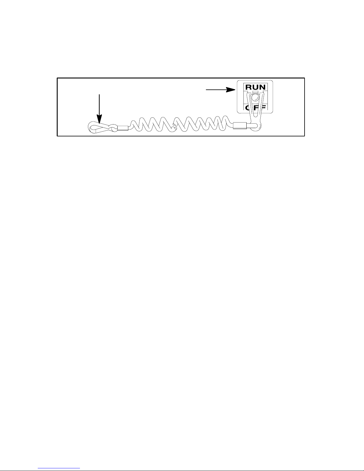
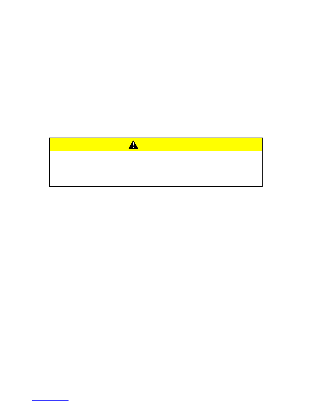
Lanyard Stop Switch
The purpose of a lanyard stop switch (1) is to turn off the engine when
the operator moves far enough away from the operator’s position (as
in accidental ejection from the operator’s position) to activate the
switch. Some remote control units are equipped with a lanyard stop
switch. A lanyard stop switch can be installed on the dashboard or
side adjacent to the operator’s position.
The lanyard is a cord usually between 4 and 5 feet (1220 and 1524
mm) in length when stretched out with an element on one end made
to be inserted into the switch and a snap (2) on the other end for
attaching to the operator. The lanyard is coiled to make its at-rest
condition as short as possible so as to minimize the likelihood of
lanyard entanglement with nearby objects. It is made as long as it is
in its stretched condition to minimize the likelihood of accidental
activation should the operator choose to move around in an area
close to the normal operator’s position. If it is desired to have a
shorter lanyard, wrap the lanyard around the operator’s wrist or le g,
or tie a knot in the lanyard.
IMPORTANT: The purpose of a lanyard stop switch is to stop
the engine when the operator moves far enough away from the
operator’s position to activate the switch. This would occur if
the operator accidentally falls overboard or moves within the
boat a sufficient distance from the operator’s position.
Accidental ejections and falls overboard are more likely to
occur in certain types of boats such as low sided sport boats o r
bass boats, and high-performance boats. Accidental ejections
and falls overboard are also likely to occur as a result of poor
operating practices such as sitting on the back of the seat or
Page 9
7
gunwale at planing speeds, standing at planing speeds, sitting
on elevated fishing boat decks, operating at planing speeds in
shallow or obstacle-infested waters, releasing your grip on a
steering wheel that is pulling in one direction, drinking alcohol
or consuming drugs, or daring, high-speed boat maneuvers.
While activation of the lanyard stop switch will stop the engine
immediately, a boat will continue to coast for some distance
depending upon the velocity and degree of any turn at shut-down.
However, the boat will not complete a full circle. While the boat is
coasting, it can cause injury to anyone in the boat’s path as seriously
as the boat would when under power.
We strongly recommend that other occupants be instructed on
proper starting and operating procedures should they be required to
operate the engine in an emergency (e.g. if the operator is
accidentally ejected).
WARNING
Should the operator fall out of the boat, the possibility of serious injury or death from being run over by the boat can be
greatly reduced by stopping the engine immediately. Always
properly connect both ends of the stop switch lanyard to the
stop switch and the operator.
Accidental or unintended activation of the switch during normal
operation is also a possibility. This could cause any, or all, of the
following potentially hazardous situations:
1 Occupants could be thrown forward due to unexpected loss of
forward motion - a particular concern for passengers in the front of
the boat who could be ejected over the bow and possibly struck by
the gear case or propeller.
2 Loss of power and directional control in heavy seas, strong
current or high winds.
3 Loss of control when docking.
WARNING
Avoid serious injury or death from deceleration forces resulting from accidental or unintended stop switch activation. The
boat operator should never leave the operator’s station without first disconnecting the stop switch lanyard from the operator.
Page 10
8
CA641
1
Page 11
9
CA620
Exhaust Emissions
Be Alert To Carbon Monoxide Poisoning
Carbon monoxide is present in the exhaust fumes of all internal
combustion engines including the outboards, stern drives and
inboard engines that propel boats, as well as the generators that
power various boat accessories. Carbon monoxide is a deadly gas
that is odorless, colorless and tasteless.
Early symptoms of carbon monoxide poisoning, which should not be
confused with seasickness or intoxication, include headache,
dizziness, drowsiness, and nausea.
WARNING
Avoid the combination of a running engine and poor ventilation. Prolonged exposure to carbon monoxide in sufficient
concentration can lead to unconsciousness, brain damage or
death.
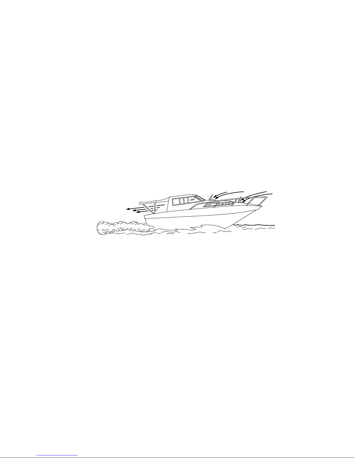
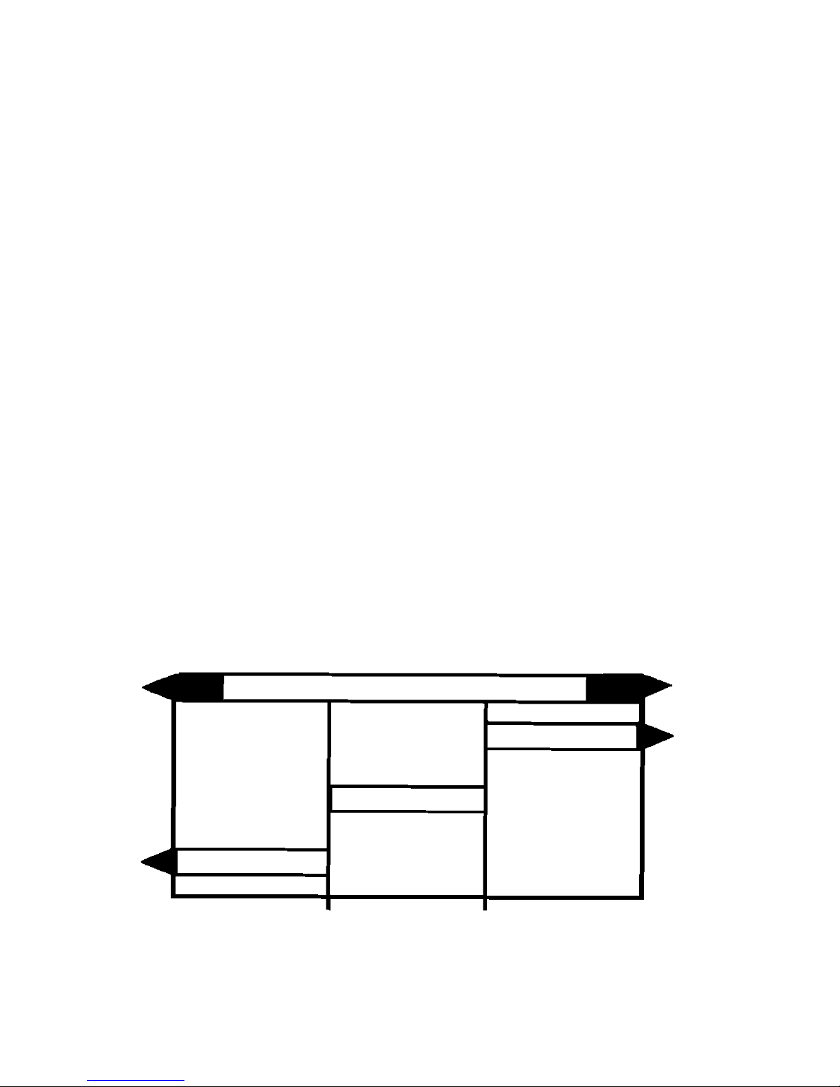
GOOD VENTILATION
Ventilate passenger area, open side curtains, or forward hatches to
remove fumes.
1 Example of desired air flow through the boat.
Page 12
10
CA642
3A
3B
Courtesy of ABYC
2A
2B
Page 13

11
CA643
POOR VENTILATION
Under certain running and/or wind conditions, permanently enclosed
or canvas enclosed cabins or cockpits with insufficient ventilation
may draw in carbon monoxide. Install one or more carbon monoxide
detectors in your boat.
Although the occurrence is rare, on a very calm day, swimmers and
passengers in an unclosed area of a stationary boat that contains or
is near a running engine may be exposed to a hazardous level of
carbon monoxide.
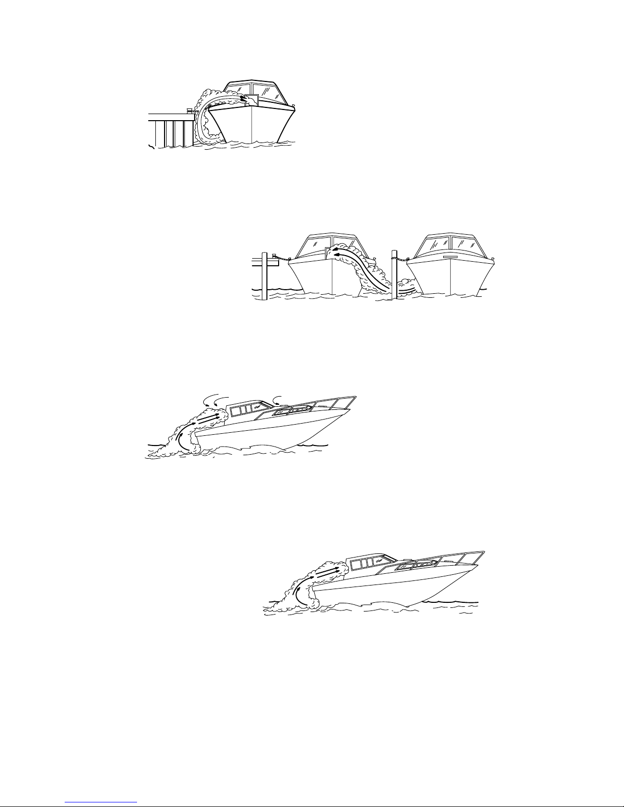
2 Examples of poor ventilation while boat is stationary:
A Running the engine when the boat is moored in a confined space.
B Mooring close to another boat that has its engine running.
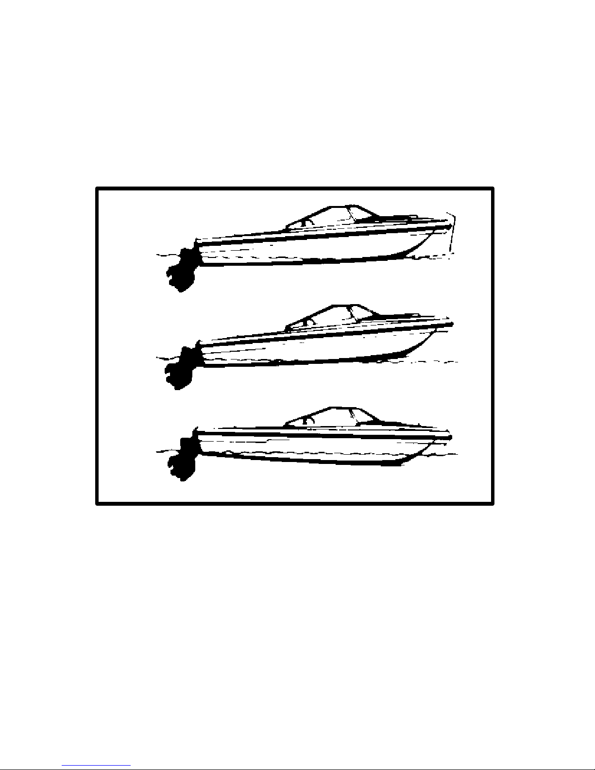
3 Examples of poor ventilation while boat is moving:
A Running the boat with the trim angle of the bow too high.
B Running the boat with no forward hatches open (station wagon
effect).
Page 14

12
CA476
Safe Boating Suggestions
In order to safely enjoy the waterways, familiarize yourself with local
and other governmental boating regulations and restrictions, and
consider the following suggestions.
• Know and obey all nautical rules and laws of the waterways.
Boat operators should complete a boating safety course. Courses
are offered in the U.S.A. by (1) The U.S. Coast Guard Auxiliary,
(2) The Power Squadron, (3) The Red Cross and (4) your state
or provincial boating law enforcement agency. Inquiries may be
made to the Boating Hotline, 1-800-368-5647 or the Boat U.S.
Foundation information number 1-800-336-BOAT.
We strongly recommend that all powerboat operators attend one of
these courses.
You should also review the NMMA Sources of Waterway Information
booklet. It lists regional sources of safety, cruising and local
navigation and is available at no charge by writing to:
Sources of Waterway Information
National Marine Manufacturers Association
410 N. Michigan Avenue
Chicago, IL 60611 U.S.A.
• Perform safety checks and required maintenance. Follow a
regular schedule and ensure that all repairs are properly made.
• Check safety equipment on board. Here are suggestions of the
types of safety equipment to carry when boating:
1 Approved fire extinguisher(s); paddle or oar.
2 Signal devices: flashlight, rockets or flares, flag and whistle or
horn.
3 Spare propeller, thrust hubs and an appropriate wrench.
4 Tools for necessary minor repairs; first aid kit and book.
5 Anchor and extra anchor line; water-proof storage containers.
6 Manual bilge pump and extra drain plugs; compass and map or
chart of area.
7 Spare operating equipment; batteries, bulbs, fuses, etc.
8 Transistor radio.
9 Drinking water.
Page 15

13
• Know signs of weather change and avoid foul weather and
rough-sea boating.
• Tell someone where you are going and when you expect to
return.
• Passenger boarding. Stop the engine whenever passengers are
boarding, unloading or are near the back (stern) of the boat. Just
shifting the drive unit into neutral is not sufficient.
• Use personal flotation devices. Federal Law requires that there
be a U. S. Coast Guard approved, wearable-type life jacket
(personal flotation device), correctly sized and readily accessible
for every person on board, plus a throwable cushion or ring. We
strongly advise that everyone wear a life jacket at all times while
in the boat.
• Prepare other boat operators. Instruct at least one person on
board in the basics of starting and operating the engine and boat
handling in case the driver becomes disabled or falls overboard.
• Do not overload your boat. Most boats are rated and certified
for maximum load (weight) capacities (refer to your boat capacity
plate). Know your boat’s operating and loading limitations. Know
if your boat will float if full of water. When in doubt, contact your
dealer or the boats manufacturer.
• Make sure everyone in the boat is properly seated. Don’t allow
anyone to sit or ride on any part of the boat that was not intended
for such use. This includes backs of seats, gunwales, transom,
bow, decks, raised fishing seats, any rotating fishing seat;
anywhere that sudden unexpected acceleration, sudden
stopping, unexpected loss of boat control or sudden boat
movement could cause a person to be thrown overboard or into
the boat. See that all passengers have a proper seat and are in
it before any boat movement.
• Never be under the influence of alcohol or drugs while
boating (it is the law). They impair your judgment and greatly
reduce your ability to react quickly.
Page 16

14
• Know your boating area and avoid hazardous locations.
• Be alert. The operator of the boat is responsible by law to
“maintain a proper lookout by sight (and hearing).” The operator
must have an unobstructed view particularly to the front. No
passengers, load, or fishing seats should block the operators view
when operating the boat above idle or planing transition speed.
Watch “the other guy,” the water and your wake.
• Never drive your boat directly behind a water skier in case
the skier falls. As an example, your boat traveling at 25 miles per
hour (40 km/hr) in 5 seconds will overtake a fallen skier who was
200 feet in front of you.
• Watch fallen skiers. When using your boat for water skiing or
similar activities, always keep a fallen or down skier on the
operator’s side of the boat while returning to attend the skier. The
operator should always have the down skier in sight and never
back up to the skier or anyone in the water.
• Report accidents. Boat operators are required by law to file a
Boating Accident Report with their state boating law enforcement
agency when their boat is involved in certain boating accidents.
A boating accident must be reported if (1) there is loss of life or
probable loss of life, (2) there is personal injury requiring medical
treatment beyond first aid, (3) there is damage to boats or other
property where the damage value exceeds $500.00 or (4) there
is complete loss of the boat. Seek further assistance from local
law enforcement.
Page 17
15
CA282
Protecting People In The Water
While You Are Cruising
It is very difficult for a person standing or floating in the water to take
quick action to avoid a boat heading in his/her direction even at slow
speed.
Always slow down and exercise extreme caution any time you are
boating in an area where there might be people in the water.
Whenever a boat is moving (coasting) and the drive unit is in neutral
position, there is sufficient force by the water on the propeller to
cause the propeller to rotate. This neutral propeller rotation can
cause serious injury.
While Boat Is Stationary
Shift the drive unit into neutral and shut off the engine before allowing
people to swim or be in the water near your boat.
WARNING
Stop your engine immediately whenever anyone in the water
is near your boat. Serious injury to the person in the water is
likely if contacted by a rotating propeller, a moving boat, a
moving gear case, or any solid device rigidly attached to a
moving boat or gear case.
CC828
High-Speed And High-Performance
Boat Operation
If your boat is considered a high-speed or high-performance boat
with which you are unfamiliar, we recommend that you never operate
it at its high speed capability without first requesting an initial
orientation and familiarization demonstration ride with your dealer or
an operator experienced with your boat. For additional information,
obtain a copy of our “Hi-Performance Boat Operation” booklet (Part
Number 90-849250--1) from your dealer, distributor, or Mercury
Marine.
Page 18

16
CA7
Conditions Affecting
Operation
Weight Distribution
Positioning of weight (passengers and gear) inside the boat has the
following effects:
Shifting weight to rear (stern) will:
• Generally increases speed and engine RPM.
• At extremes can cause boat to porpoise.
• Causes bow to bounce in choppy water.
• Increases danger of following wave splashing into boat when
coming off plane.
Shifting weight to front (bow) will:
• Improve ease of planing.
• Improve rough water ride.
• At extremes, can cause boat to veer back and forth (bow steer).
CA8
Bottom Of Boat
To maintain maximum speed, the following conditions of the boat
bottom should be observed.
A. Clean, free of barnacles and marine growth.
B. Free of distortion; nearly flat where it contacts the water.
C. Straight and smooth, fore and aft.
Marine vegetation may accumulate when boat is docked. This
growth must be removed before operation; it may clog water inlets
and cause engine to overheat.
Page 19

17
CA9
Cavitation
Cavitation occurs when water flow cannot follow the contour of a
fast-moving underwater object, such as a gear housing or propeller.
Cavitation permits the propeller to speed up, but the boat speed to
reduce. Cavitation can seriously erode the surface of the gear
housing or propeller. Common causes of cavitation are:
A. Weeds or other debris snagged on propeller or gear housing.
B. Bent propeller blade or damaged gear housing skeg.
C. Raised burrs or sharp edges on propeller or gear housing.
CA10
Ventilation
Ventilation is caused by surface air or exhaust gases which are
introduced around the propeller resulting in propeller speedup and
a reduction in boat speed. Excessive ventilation is annoying and
usually caused by:
A. Drive unit trimmed out too far.
B. A missing propeller diffuser ring.
C. A damaged propeller or gear housing, which allows exhaust
gases to escape between propeller and gear housing.
D. Drive unit installed too high on transom.
CA406
Propeller Selection
IMPORTANT: Installed propeller must allow engine to run at
its specified maximum wide-open-throttle revolutions per
minute (RPM). Use an accurate service tachometer to verify
engine operating RPM.
It is the responsibility of the boat manufacturer and/or the selling
dealer to equip the power package with the correct propeller(s).
Specified engine wide-open-throttle (WOT) and operating RPM
range are listed in “SPECIFICATIONS.”
Page 20

18
IMPORTANT: The engines covered in this manual (Except 3.0L)
are equipped with an RPM rev-limiter that is set to an upper (or
limited) RPM amount. This limit is slightly above the normal
operating range of the engine and is designed to help prevent
damage from excessive engine RPM. Once the RPM drops into
the recommended operating RPM range normal engine
operation resumes.
Select a propeller that will allow the engine power package to operate
at or near the top end of the recommended wide-open-throttle
operating RPM range with a normal load. High RPM, caused by an
excessive trim angle, should not be used in determining correct
propeller selection.
If full throttle operation is below the recommended range, the
propeller must be changed to prevent loss of performance and
possible engine damage. On the other hand, operating an engine
above the recommended operating RPM range will cause higher
than normal wear and/or damage. Generally, there is a 200-300 RPM
change between propeller pitches.
After initial propeller selection, the following common problems may
require that the propeller be changed to a lower pitch:
• Warmer weather and greater humidity cause an RPM loss.
• Operating in a higher elevation causes an RPM loss.
• Operating with a damaged propeller or dirty boat bottom causes
an RPM loss.
• Operating with increased load (additional passengers, pulling
skiers, etc.).
For better acceleration, such as is needed for water skiing, use the
next lower pitch propeller. However, do not operate at full throttle
when using the lower pitch propeller but not pulling skiers.
Page 21

19
CA12
How Elevation And Climate Affect Performance
Elevation has a very noticeable effect on the wide-open-throttle
power of an engine. Since air (containing oxygen) gets thinner as
elevation increases, the engine begins to starve for air. Humidity,
barometric pressure and temperature do have a noticeable effect on
the density of air. Heat and humidity thin the air. This condition can
become particularly annoying when the propeller testing was done
on a cool, dry day. Then later; on a hot, sultry day, the boat doesn’t
seem to have the same performance.
Although some performance can be regained by dropping to a lower
pitch propeller, the basic problem still exists. In some cases, a gear
ratio change to more reduction is possible and very beneficial.
Summer conditions of high temperature, low barometric pressure
and high humidity all combine to reduce the engine power. This, in
turn, is reflected in decreased boat speeds, as much as 2 or 3 miles
per hour in some cases. Nothing will regain this speed for the boater,
but the coming of cool, dry weather.
In pointing out the practical consequences of weather effects, an
engine running on a hot, humid, summer day, may encounter a loss
of as much as 14% of the horsepower it would produce on a dry, brisk
spring or fall day. With the drop in available horsepower, this
propeller will, in effect, become too large. Consequently, the engine
operates at less than its recommended RPM. This will result in
further loss of horsepower at the propeller with another decrease in
boat speed. This secondary loss, however, can be somewhat
regained by switching to a lower-pitch propeller that allows the
engine to again run at recommended RPM.
For boaters to realize optimum engine performance under changing
weather conditions, it is essential that the engine be propped to allow
it to operate at or near the top end of the recommended maximum
RPM range at wide-open-throttle with a normal boat load.
Not only does this allow the engine to develop full power, but equally
important is the fact that the engine also will be operating in an RPM
range that discourages damaging detonation. This, of course,
enhances overall reliability and durability of the engine.
Page 22

20
CA13
Important Information
Operation And Maintenance
OWNER/OPERATOR RESPONSIBILITIES
It is the operator’s responsibility to perform all safety checks; to
ensure that all lubrication and maintenance instructions are
complied with for safe operation and to return the unit to an
Authorized MerCruiser Dealer for a periodic checkup.
Normal maintenance service and replacement parts are the
responsibility of the owner/operator and as such, are not considered
defects in workmanship or material within the terms of the warranty.
Individual operating habits and usage contribute to the need for
maintenance service.
Proper maintenance and care of your power package will assure
optimum performance and dependability, and will keep your overall
operating expenses at a minimum. See your Authorized MerCruiser
Dealer for service aids.
CA14
DEALER RESPONSIBILITIES
In general, a dealer’s responsibilities to the customer include
predelivery inspection and preparation such as:
• Make sure that the boat is properly equipped.
• Prior to delivery, make certain that the MerCruiser power package
and other equipment are in proper operating condition.
• Make all necessary adjustments for maximum efficiency.
• Familiarize the customer with the on-board equipment.
• Explain and demonstrate the operation of the power package and
boat.
• At the time of delivery, the dealer should provide you with a copy
of a Predelivery Inspection Checklist.
• Your selling dealer should fill out the Warranty Registration Card
completely and mail it to the factory immediately upon sale of the
new product.
Page 23

21
CA407
Freezing Temperature Operation
IMPORTANT: If boat is operated during periods of freezing
temperature, precautions must be taken to prevent freezing
damage to power package. Damage caused by freezing IS NOT
covered by MerCruiser Limited Warranty.
CA17
Drive Unit Impact Protection
The Power Trim hydraulic system is designed to provide impact
protection for drive unit. If a submerged object is struck while boat is
moving forward, the hydraulic system will cushion the kickup of drive
unit as it clears the object, reducing damage to unit. After drive unit
has cleared object, the hydraulic system allows drive unit to return
to original operating position, preventing loss of steering control and
engine overspeed.
Use extreme caution when operating in shallow water or where
underwater objects are known to be present. Use extreme care to
prevent striking submerged object while operating in REVERSE. No
impact protection is provided in REVERSE.
If drive unit should strike a submerged object, stop engine as soon
as possible and inspect drive unit for damage. If damage is present
or suspected, boat should be taken to an Authorized MerCruiser
Dealer for thorough inspection and necessary repair. Operating a
damaged drive unit could cause additional damage to other parts of
drive unit, or could affect control of boat. If continued running is
necessary, do so at greatly reduced speeds.
IMPORTANT: Impact protection system cannot be designed to
ensure total protection from impact damage under all
conditions.
CA408
Drain Plug and Bilge Pump
The engine compartment in your boat is a natural place for water to
collect. For this reason, boats are normally equipped with a drain
plug and/or a bilge pump. It is very important to check these items on
a regular basis to ensure that the water level does not rise to come
in contact with your power package. Components on your engine will
be damaged if submerged. Damage caused by submersion is not
covered by the MerCruiser Limited Warranty.
Page 24

22
CA621
Emissions Information (Europe Only)
Your engine may be equipped with special design features and
special tuning to minimize the emission output from the engine. If so,
it is very important that you strictly adhere to the following:
• Recommended maintenance schedules particularly the ignition
system.
• Proper engine tuning procedures to ensure these features remain
in good operating order.
• Proper steps to maintain the engine within specifications.
Use only MerCruiser replacement parts to ensure compliance with
emission regulations.
IMPORTANT: The testing dealer or agency will be equipped
with the appropriate test equipment and adapters for this
engine. Refer to “Emissions Testing” procedure found later in
this manual.
CA409
Attention Required After Submersion
• Before recovery, contact an Authorized MerCruiser Dealer.
• After recovery, immediate service by an Authorized MerCruiser
Dealer is required to prevent serious damage to power package.
CA19
Trailering Boat
Boat can be trailered with drive unit in “up” or “down” position.
Adequate road clearance is required between road and gear housing
skeg when trailering with drive unit in “down” position.
If adequate road clearance is a problem, place drive unit in full trailer
position and support with an optional trailer kit which is available from
your Authorized MerCruiser Dealer.
Page 25

23
CA20
Launching And Boat Operation Care
CAUTION
During launching from a trailer, if the unloading ramp is steep
or the trailer bed must be tilted, the boat may enter the water
rapidly and at a steep angle. This may force water through the
exhaust system into the cylinders. The more weight on the
transom, the more likely this is to occur.
Slowing down rapidly or stopping suddenly may cause a following wave to “swamp” the transom. In this instance, water
may enter the cylinders through the exhaust system.
When backing up rapidly, the same situation may occur as
stated in the preceding paragraph.
In any of these situations, water entering the engine could cause
severe damage to internal parts. Refer to “Attention Required After
Submersion.”
CA21
Stolen Power Package
If your power package is stolen, immediately advise the local
authorities and Mercury Marine of the model and serial number(s)
and to whom the recovery is to be reported. This “Stolen Motor”
information is placed into a file at Mercury Marine to aid authorities
and dealers in recovery of stolen motors.
Page 26

24
CA22
Replacement Service Parts
WARNING
Electrical, ignition and fuel system components on MerCruiser gasoline power packages are designed and manufactured
to comply with U.S. Coast Guard rules and regulations to minimize risks of fire or explosion.
Use of replacement electrical, ignition or fuel system components, which do not comply to these rules and regulations,
could result in a fire or explosion hazard and should be
avoided.
When servicing the electrical, ignition and fuel systems, it is
extremely important that all components are properly installed and tightened. If not, any electrical or ignition component would permit sparks to ignite fuel vapors from fuel system leaks, if they existed.
Marine engines are expected to operate at or near full-throttle for
most of their life. They are also expected to operate in both fresh and
saltwater environments. These conditions require numerous special
parts. Care should be exercised when replacing marine engine parts
as specifications are quite different from those of the standard
automotive engine.
For example, one of the most important, and probably the least
suspected special replacement part, is the cylinder head gasket.
Since saltwater is highly corrosive, the steel-type automotive head
gasket cannot be used. A marine engine head gasket uses special
materials to resist corrosive action.
Since marine engines must be capable of running at or near
maximum RPM much of the time, special valve springs, valve lifters,
pistons, bearings, camshafts and other heavy-duty moving parts are
required for long life and peak performance.
These are but a few of the many special modifications that are
required in MerCruiser marine engines to provide long life and
dependable performance.
Page 27

25
CA410
Do-It-Yourself Maintenance Suggestions
If you are one of those persons who likes to do-it-yourself, here are
some suggestions for you.
• Present-day marine equipment, such as your MerCruiser power
package, are highly technical pieces of machinery. Electronic
ignition and special fuel delivery systems provide greater fuel
economies, but also are more complex for the untrained
mechanic.
• Do not attempt any repairs which are not covered in this manual
unless you are aware of the precautions (“Cautions” and
“Warnings”) and procedures required. Your safety is of our
concern.
• If you attempt to service the product yourself, we suggest you
order the Maintenance Procedures Manual for that model. This
manual outlines the correct procedures to follow. Do not attempt
repairs if you do not understand the procedures.
• There are special tools and equipment that are required to
perform some repairs. Do not attempt these repairs unless you
have these special tools and/or equipment. You can cause
damage to the product in excess of the cost a dealer would charge
you.
• Also, if you partially disassemble an engine or drive assembly and
are unable to repair it, the dealer’s mechanic must reassemble the
components and test to determine the problem. This will cost you
more than taking it to the dealer immediately upon having a
problem. It may be a very simple adjustment to correct the
problem.
• Do not telephone the dealer, service office or the factory to
attempt for them to diagnose a problem or request the repair
procedure. It is difficult for them to diagnose a problem over the
telephone.
• Your Authorized Dealer is there to service your power package.
They have qualified factory-trained mechanics.
It is recommended you have the dealer do periodic maintenance
checks on your power package. Have them winterize it in the fall and
service it before the boating season. This will reduce the possibility
of any problems occurring during your boating season when you
want trouble-free boating pleasure.
Page 28

26
CA742
Multiple EFI Engine Battery Precautions
Situation
Alternators: Alternators are designed to charge the battery that sup-
plies electrical power to the engine that the alternator is mounted on.
When batteries for two different engines are connected, one alternator will supply all of the charging current for both batteries. Normally,
the other engine’s alternator will not be required to supply any charging current.
EFI Electronic Control Module (ECM): The ECM requires a stable
voltage source. During multiple engine operation, an onboard electrical device may cause a sudden drain of voltage at the engine’s battery. The voltage may go below the ECM’s minimum required voltage. Also, the alternator on the other engine may now start charging.
This could cause a voltage spike in the engine’s electrical system.
In either case, the ECM could shut off. When the voltage returns to
the range that the ECM requires, the ECM will reset itself. The engine
will now run normally. This ECM shut down usually happens so fast
that the engine just appears to have an ignition miss.
Recommendations
Batteries: Boats with multi-engine EFI power packages require
each engine be connected to its own battery. This ensures that the
engine’s Electronic Control Module (ECM) has a stable voltage
source.
Battery Switches: Battery switches should always be positioned so
each engine is running off its own battery. DO NOT operate engines
with switches in BOTH or ALL position. In an emergency, another
engine’s battery can be used to start an engine with a dead battery.
Generators: The generator’s battery should be considered another
engine’s battery.
Page 29
27
CA623
Diagnosing EFI Problems (If Equipped)
NOTE: All references to EFI models apply to EFI and MPI engines.
Your Authorized MerCruiser Dealer has the proper service tools for
diagnosing problems on Electronic Fuel Injection (EFI) Systems. The
Electronic Control Module (ECM) on these engines has the ability to
detect some problems with the system when they occur, and store
a “Trouble Code” in the ECM’ s memory. This code can then be read
later by a service technician using a special diagnostic tool.
CA624
Water Separating Fuel Filter
CAUTION
The electric fuel pump and factory installed water separating
fuel filter have been carefully designed to function properly together. Do not install additional fuel filters and/or water separating fuel filters between fuel tank and engine.
The installation of additional filters may cause:
• Fuel Vapor Locking
• Difficult Warm-Starting
• Piston Detonation Due to Lean Fuel Mixture
• Poor Driveability
Page 30

28
CA413
20-Hour Break-In Period
IMPORTANT: The first 20 hours of operation is the engine
break-in period. Correct break-in is essential to obtain
minimum oil consumption and maximum engine performance.
During this break-in period, the following rules must be
observed:
• Do not operate below 1500 RPM for extended periods of time for
first 10 hours. Shift into gear as soon as possible after starting and
advance throttle above 1500 RPM if conditions permit safe
operation.
• Do not operate at one speed consistently for extended periods.
• Do not exceed 3/4 throttle during first 10 hours. During next 10
hours, occasional operation at full throttle is permissible (5
minutes at a time maximum).
• Avoid full throttle acceleration from IDLE speed.
• Do not operate at full throttle until engine reaches normal
operating temperature.
• Frequently check crankcase oil level. Add oil if needed. It is
normal for oil consumption to be high during break-in period.
Page 31

29
CA211
After Break-In Period
To help extend the life of your MerCruiser power package, the
following recommendations should be considered;
• Use a propeller that allows the engine to operate at or near the top
of the maximum RPM range (See “Specifications” section) when
at full throttle with a normal boat load.
• Operation at 3/4 throttle setting or lower is recommended. Refrain
from prolonged operation at maximum (full throttle) RPM.
CA414
End of First Season Checkup
At the end of the first season of operation, an Authorized MerCruiser
Dealer should be contacted to discuss and/or perform various
scheduled maintenance items. If you are in an area where the
product is operated continuously (year-round operation), you should
contact your dealer at the end of the first 100 hours of operation, or
once yearly, whichever occurs first.
Page 32

30
CA26
70514
70515
70516
70523
70517
70522
70518
70521
70520
70519
1
2
3
4
5
6
7
8
9
10
Page 33

31
CA470
Operation
Instrumentation
The following is a brief explanation of instrumentation typically found
on some boats. The owner/operator should be familiar with all
instruments and their functions on the boat. Because of the large
variety of instrumentation and manufacturers, you should have your
boat dealer explain the particular gauges and normal readings that
will appear on your style gauges.
1 Speedometer: Indicates boat speed.
2 Tachometer: Indicates engine RPM.
3 Oil Pressure Gauge: Indicates engine oil pressure.
4 Battery Meter: Indicates battery voltage.
5 Water Temperature Gauge: Indicates engine operating
temperature.
6 Fuel Gauge: Indicates quantity of fuel in tank.
7 Power Trim Gauge: Indicates drive unit angle (trim up/out and
down/in).
8 Hour Meter: Records engine running time.
9 Bilge Blower Switch: Operates bilge blower (If so equipped - See
“Starting, Shifting and Stopping” procedure).
10Ignition Switch: Allows operator to start and stop engine.
Page 34

32
CB218
705161
2
3
71987
70518
Page 35

33
CA625
Audio Warning System
Your MerCruiser power package may be equipped with an Audio
Warning System.
The audio warning system horn will sound if one of the following
occur:
1 Engine Oil Pressure Too Low
2 Engine Temperature Too Hot
3 Drive Oil Level Too Low
NOTE: To test the system:
Turn the ignition switch to the ON position without cranking the engine. The horn will sound if the system is working correctly.
CAUTION
Avoid engine damage. Do not operate engine once the buzzer
has sounded EXCEPT TO AVOID A HAZARDOUS SITUATION.
The Audio Warning System will not protect the engine from
damage. It i s designed to warn the operator that a problem has
occurred.
When the horn sounds with the engine running, stop engine
immediately. Investigate cause and correct it, if possible. If cause
cannot be determined, consult your Authorized MerCruiser Dealer.
Page 36

34
CA756
74898
1A
74907
2,3
4
76037
1B
Page 37

35
CA698
Electrical System Overload Protection
If an electrical overload occurs, a fuse will blow or the circuit breaker
will trip open. The cause must be found and corrected before
replacing fuse or resetting circuit breaker.
1 On the following models, a circuit breaker provides protection for
engine wiring harness and instrumentation power lead. Reset by
pushing RESET button IN.
A 4.3LH and 5.7L Models
B 4.3L EFI, 5.0L EFI, 5.7L EFI and 350 Mag MPI Models
2 On 3.0L, 4.3L and 5.0L Models: A 55 Amp fuse is located on the
large post of the starter solenoid. This fuse is designed to protect the
engine wiring harness if an electrical overload occurs.
3 On EFI Models: A 90 Amp fuse is located on the large post of the
starter solenoid. This fuse is designed to protect the engine wiring
harness if an electrical overload occurs.
NOTE: In an emergency, when engine must be operated and cause
for high current draw cannot be located and corrected, turn OFF or
disconnect all accessories connected to engine and instrumentation
wiring. Reset circuit breaker or replace fuse as appropriate for your
model. If circuit remains open, electrical overload has not been eliminated. Further checks must be made on electrical system.
4 On EFI Models: Three fuses are located on the port side of the
engine. These fuses control various EFI circuits.
A Fuel Pump Fuse - 15 Amp
B ECM / Injector Fuse - 10 Amp
C ECM / Battery Fuse - 15 Amp
Page 38

36
CA697
70528
70527
70526
9
7
8
5A
5B
5C
5
70525
6
Page 39

37
CA696
5 4.3L EFI Models: Three fuses are located in a single block in the
fuel injection system electrical box. These fuses control various EFI
circuits.
A Fuel Pump Fuse - 15 Amp
B ECM / Injector Fuse - 10 Amp
C ECM / Battery Fuse - 15 Amp
6 A 20 amp fuse may be located in ignition switch “I” terminal lead
to protect electrical system. Check for blown fuse if key is turned to
START and nothing happens (and circuit breaker, if equipped, is not
tripped).
CA482
7 The Power Trim System is protected from overload by 110 amp
fuse and a 20 amp in-line fuse on Power Trim pump.
8 Quicksilver Three-Button Power Trim Control Panel is further
protected by a 20 amp in-line fuse.
9 The Quicksilver MerCathode System has a 20 amp in-line fuse is
in the wire which connects to positive (+) terminal on controller. If fuse
is blown, system will not operate and a loss of corrosion protection
will result.
Page 40
38
CB181
1
4
5
2
3
6
7
Page 41

39
CB182
Remote Controls (Panel Mounted)
Your boat may be equipped with one of many Quicksilver remote
controls available. All controls feature an integral safety switch that
allows starting engine in NEUTRAL only. Also, all controls may not
have all features shown. If boat is equipped with a remote control
other than shown, consult your dealer for a description and/or
demonstration of the control.
1 Neutral Lock Bar - Prevents accidental shift and throttle
engagement. Neutral lock bar must be pulled “Up” to move the
control handle out of neutral.
2 Throttle Only Button - Allows engine throttle advancement
without shifting the engine. This is done by disengaging the shift
mechanism from the control handle. The throttle only button can be
depressed only when the remote control handle is in the “Neutral”
position, and should only be used to assist in starting the engine.
3 Power Trim Switch - See “Power Trim” for detailed power trim
operating procedures.
4 Trailer Switch - Used to raise drive unit for trailering, launching,
breaching or shallow water operation. See “Power Trim” for detailed
trailer switch operation.
5 Lanyard Stop Switch - Turns ignition “Off” whenever the
operator (when attached to the lanyard) moves far enough away
from the operator’s position to activate the switch. See “Lanyard Stop
Switch” at the front of this manual for safety warning on the use of this
switch.
6 Control Handle Tension Adjustment Screw - This screw can be
adjusted to “Increase” or “Decrease” the tension on the control
handle. This will help prevent “Creep” of the remote control handle.
Turn screw “Clockwise” to increase tension and “Counterclockwise”
to decrease tension. Adjust to tension desired.
7 Control Handle - Operation of the shift and throttle are controlled
by the movement of the control handle. “Push” the control handle
forward from “Neutral” with a quick firm motion to the first detent for
“Forward” gear. Continue pushing forward to increase speed. Pull
the control handle back from “Neutral” with a quick firm motion to the
first detent for “Reverse” gear. Continue pushing back to increase
speed.
Page 42

40
CB183
1
4
2
6
3
2
4
3
1
6
5
5
Page 43

41
CB184
Remote Controls (Console Mounted)
1 Control Handle(s) - Operation of the shift and throttle are
controlled by the movement of the control handle. “Push” the control
handle forward from “Neutral” with a quick firm motion to the first
detent for “Forward” gear. Continue pushing forward to increase
speed. Pull the control handle back from “Neutral” with a quick firm
motion to the first detent for “Reverse” gear . Continue pushing back
to increase speed.
2 Throttle Only Button - Allows engine throttle advancement
without shifting the engine. This is done by disengaging the shift
mechanism from the control handle. The throttle only button can be
depressed only when the remote control handle is in the “Neutral”
position, and should only be used to assist in starting the engine.
3 Control Handle Tension Adjustment Screw - This screw can be
adjusted to “Increase” or “Decrease” the tension on the control
handle (cover must be removed to adjust). This will help prevent
“Creep” of the remote control handle. Turn screw “Clockwise” to
increase tension and “Counterclockwise” to decrease tension.
Adjust to tension desired.
4 Power Trim Switch - See “Power Trim” section for detailed power
trim operating procedures.
5 Trailer Switch - Used to raise drive unit for trailering, launching,
breaching or shallow water operation. See “Power Trim” for detailed
trailer switch operation.
6 Power Trim Adjustment Switches (Used on Three Button
Trim Control Only) - See “Power Trim” section for detailed power
trim operating procedures.
Page 44

42
CB185
3
4
70537
71339
1
2
Page 45
43
CB186
Remote Controls (Two Lever)
1 Shift Lever - shifts unit into gear with full lever movement. Move
lever forward to shift to FORWARD gear. Move lever backward to
shift to REVERSE gear. Lever in full vertical position shifts to
NEUTRAL.
CAUTION
Never shift unit into or out of gear unless throttle lever is at idle
RPM.
2 Throttle Lever - allows engine RPM to be increased or decreased.
3 FRICTION Screw - adjusts control handle friction so motor speed
can be set and driver does not have to hold handle.
Turn screw clockwise to increase friction. Do not thread screw all the
way out.
4 DETENT Screw - controls the effort needed to move control
handle out of NEUTRAL. To increase tension, turn screw clockwise;
to decrease, turn screw counterclockwise. Do not thread screw all
the way out.
IMPORTANT: Boats equipped with dual power packages may
have both shift levers on one control and both throttle levers on
the other control.
Page 46
71338
1
3 TO 5
DEGREES
44
CA34
Page 47
45
CA418
Power Trim
Power Trim allows the operator to adjust the drive angle, while
underway, to provide the ideal boat angle for varying load and water
conditions. Also, the Power Trim system “Trailering” feature allows
the operator to raise and lower the drive unit for trailering, beaching,
launching and low speed (below 1200 RPM engine speed), shallow
water operation.
CAUTION
Never trim the drive unit UP/OUT using TRAILER switch while
boat is underway at engine speeds above 1200 RPM. Use extreme caution when operating with drive unit raised. Severe
damage to the drive unit may result if unit is raised beyond the
gimbal ring support flanges at engine speeds above 1200
RPM.
1 In most cases, best overall performance is obtained with the drive
unit adjusted so the boat bottom will run at a 3° to 5° angle to the
water.
Trimming Drive Unit UP/OUT Can:
• Generally increase top speed.
• Increase clearance over submerged objects or a shallow bottom.
• Cause boat to accelerate and plane off slower.
• In excess, cause boat “porpoising” (bouncing) or propeller
ventilation.
• Cause engine overheating if trimmed UP/OUT to a point where
any cooling water intake holes are above the water line.
Trimming Drive Unit DOWN/IN Can:
• Help the boat accelerate and plane off quicker.
• Generally improve the ride in choppy water.
• In most cases, reduce boat speed.
• If in excess, lower the bow of some boats to a point at which they
begin to plow with their bow in the water while on plane. This can
result in an unexpected turn in either direction called “bow
steering” or “over steering” if any turn is attempted, or if a
significant wave is encountered.
Page 48

46
CB187
1
3
2
6
4
5
73976
73977
Page 49

47
CB188
POWER TRIM OPERATION - PANEL MOUNT
REMOTE CONTROL
IMPORTANT: If TRAILER button is held depressed after drive
unit reaches end of upward travel, an internal circuit breaker will
open and pump will stop. Should this happen, release button
and allow motor to cool for about one minute. Circuit breaker
will reset and Power Trim operation may be resumed.
1 Trailer Position: Press button until drive unit reaches desired
height.
2 Trim Up/Out: Press UP on Trim switch until drive unit reaches
desired trim position.
3 Lower Drive Unit: Press DOWN on Trim switch until drive unit
reaches desired position.
CB189
POWER TRIM OPERATION - CONSOLE MOUNT
REMOTE CONTROL (SINGLE ENGINE VERSION)
4 Trailer Position: Press button until drive unit reaches desired
height.
5 Trim Up/Out: Press UP on Trim switch until drive unit reaches
desired trim position.
6 Lower Drive Unit: Press DOWN on Trim switch until drive unit
reaches desired position.
Page 50

48
CB190
4
2A
1
1
2B
3
73978
73979
Page 51

49
CA627
POWER TRIM OPERATION - DUAL ENGINE CONSOLE
MOUNT REMOTE CONTROL (TWO BUTTON AND THREE
BUTTON VERSIONS)
IMPORTANT: If TRAILER button is held depressed after drive
unit reaches end of upward travel, an internal circuit breaker will
open and pump will stop. Should this happen, release button
and allow motor to cool for about one minute. Circuit breaker
will reset and Power Trim operation may be resumed.
CAUTION
When lowering or raising sterndrives equipped with a dual
engine tie bar kit, the sterndrives must be raised or lowered
evenly to prevent the tie bar from becoming twisted. Failure to
raise or lower sterndrives evenly may result in tie bar or sterndrive damage.
1 Trailer Button (Both Versions) - Press button until drive unit
reaches desired height for trailering drive units.
2 Two Button Trim Control (Dual Buttons in Handle) - used to
control both drive units from the handle. Press UP on button(s) to trim
drive unit UP/OUT. Press down on button(s) to trim drive unit
DOWN/IN.
A Forward Trim Button - Used to trim the port drive unit.
B Rear Trim Button - Used to trim the starboard drive unit.
3 Three Button Trim Control (Trim Adjustment Switches) - With
a single integral trim button in the handle to control two drive units
simultaneously, these two switches control the fine tune adjustment
of each drive unit. Using these Fine Tune Switches, set each drive
unit to the desired trim angle. Then use the single trim switch in the
handle to control the trim of both drive units simultaneously.
4 Three Button Trim Control (Single Trim Switch in Handle) -
used to trim both drives simultaneously after drives have been
fine-tuned as described above.
Page 52
50
CB192
70540
70540
70540
1
2
3
Page 53

51
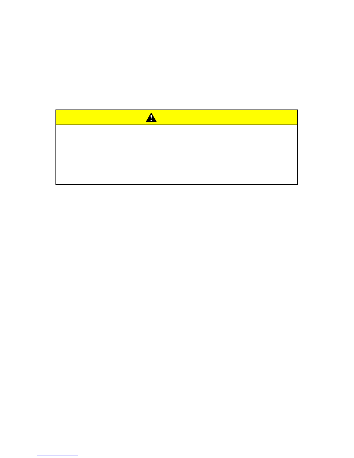
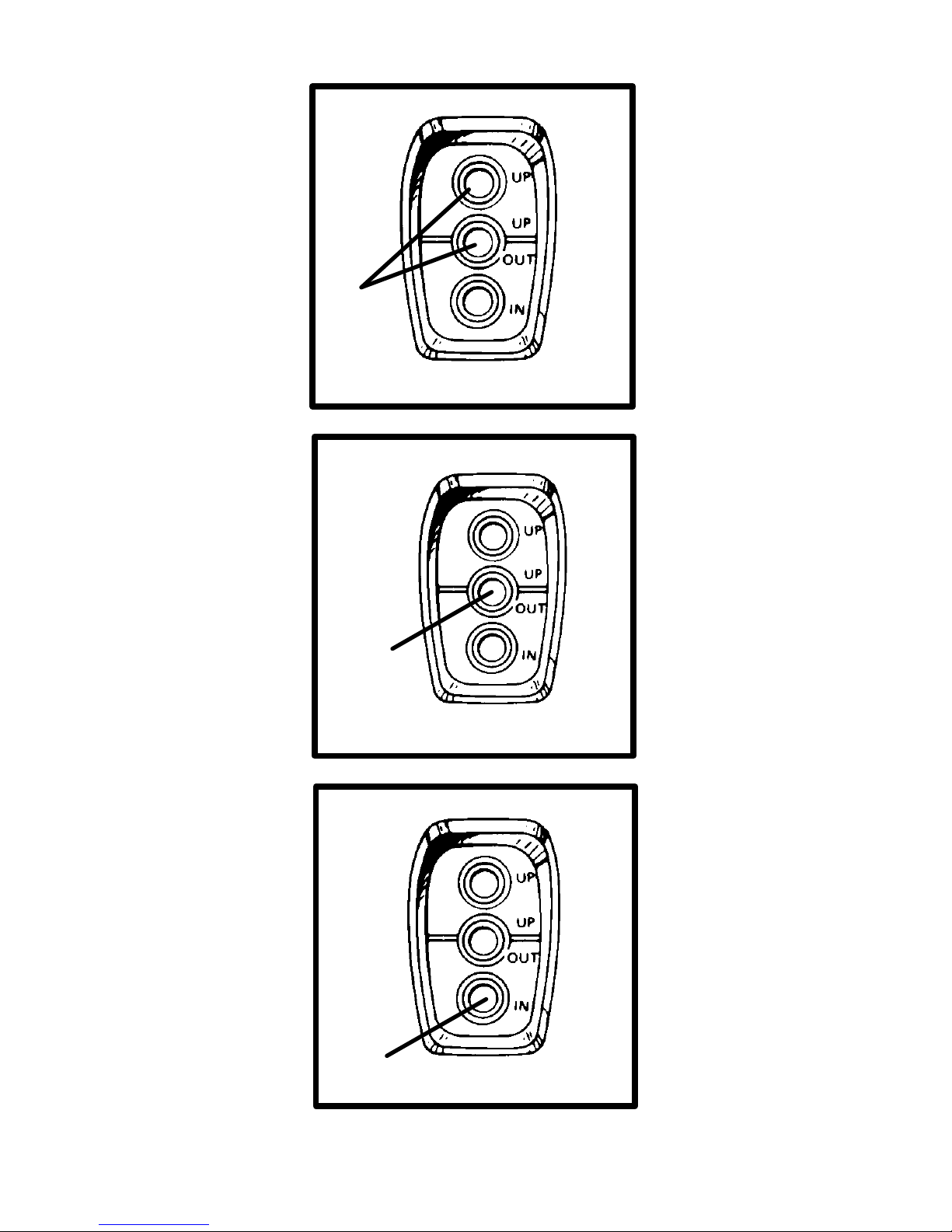
CB193
POWER TRIM OPERATION - THREE BUTTON TRIM PANEL
(USED ON MODELS WITH TWO-LEVER CONTROL)
IMPORTANT: If TRAILER button is held depressed after drive
unit reaches end of upward travel, an internal circuit breaker will
open and pump will stop. Should this happen, release button(s)
and allow motor to cool for about one minute. Circuit breaker
will reset and Power Trim operation may be resumed.
1 Trailer Position: Simultaneously press the UP button (top) along
with the UP/OUT button (center) until drive unit reaches desired
trailer position.
2 Trim Drive Unit UP/OUT: Press center UP/OUT button until drive
unit reaches desired trim position.
3 Trim Drive Unit IN/DOWN: Press IN button until drive unit reaches
desired trim position.
Page 54

52
CA757
Starting, Shifting And Stopping
WARNING
Before starting engine, operate bilge blower for at least five
minutes to remove any explosive fumes from engine compartment. If boat is not equipped with a bilge blower , open engine
hatch and leave open while starting engine.
IMPORTANT: Observe the following:
• Do not start engine without water being supplied to seawater
pickup pump (to prevent pump or engine damage).
• Do not operate starter motor continuously for more than 30
seconds.
• On Carbureted Engines: When engine starts, quickly reduce
throttle setting to avoid exceeding 1500 RPM.
• Never shift drive unit unless engine is at Idle RPM.
Perform the following as appropriate:
1 Check all items listed in OPERATION CHART.
2 Perform any other necessary checks, as indicated by your dealer,
or specified in your boat owner’s manual.
3 Place drive unit in full down/in position.
4 Place control handle in NEUTRAL.
5 Refer to A or B as appropriate for your model.
A Carbureted Engine
- Push THROTTLE ONL Y button and position
throttle setting as follows:
COLD ENGINE - Move control/throttle lever to full throttle, then
return to about 1/4 throttle. In extreme cold it may be necessary
to pump lever more than once.
WARM ENGINE - Move control/throttle lever to 1/4 throttle position.
FLOODED ENGINE - Move control/throttle lever to full throttle. Be
prepared to decrease engine speed to 1000-1500 RPM as soon
as engine starts.
Page 55

53
B EFI Engine - Position throttle setting as follows:
COLD ENGINE - Leave in neutral/idle speed position.
WARM ENGINE - Leave in neutral/idle speed position.
FLOODED ENGINE - Turn ignition switch to ON position. Push
the THROTTLE ONLY button and place the throttle lever at 50%
position. Attempt to start engine. As soon as engine starts, return
throttle to the idle position.
6 Turn ignition key to START. Release key when engine starts and
allow switch to return to RUN position.
7 Carbureted Engines - Move control/throttle lever back to
decrease engine RPM to 1000-1500 RPM if necessary.
8 Check oil pressure gauge immediately after engine starts. If oil
pressure is not within specified range (see SPECIFICATIONS), stop
engine immediately and determine cause.
9 If engine is cold, run engine for 1 or 2 minutes at fast idle
(1000-1500 RPM).
10After engine has warmed up, check water temperature gauge to
ensure that engine temperature is not abnormally high. If it is, stop
engine immediately and determine cause.
11Be sure charging system is functioning correctly.
12Observe power package for fuel, oil, water and exhaust leaks.
13To shift drive unit, return control/throttle lever to NEUTRAL. Move
control/shift lever with a firm, quick motion forward to shift to
FORWARD gear, or backward to shift to REVERSE. After shifting
drive unit, advance throttle to desired setting.
14Move control/shift lever to NEUTRAL and allow engine to drop to
IDLE speed. If engine has been run at high speed for a long period
of time, allow engine to cool by running at IDLE speed for 3 to 5
minutes.
15 Turn ignition key to OFF.
Page 56

54
CC829
CAUTION
To avoid possible ingestion of water that can damage engine
components:
• Do not turn the ignition key off when the engine is running
above idle speed.
• Do not use the lanyard stop switch to shut off the engine
above idle speed.
• When coming off plane, if a large following wave may roll
over the boat’s transom, apply a short, light burst of throttle
to minimize the wave action against the stern of the boat.
• Do not come off plane quickly, shift into reverse and shut
off engine.
CB575
IMPORTANT: Avoid stopping engine if the drive unit is in gear.
If engine does stop with drive unit in gear, refer to the following
procedure:
1 Push and pull repeatedly on remote control handle until handle re-
turns to the neutral detent position. This may take several tries if the
power package was operating above idle RPM when the engine
stopped.
2 After handle returns to the neutral detent position, resume normal
starting procedures.
Page 57

55
CA41
Operation Chart
BEFORE
STARTING
AFTER
STARTING
WHILE
UNDERWAY
AFTER
STOPPING
Open engine
hatch.
Observe all
gauges to
check
condition of
engine. If not
normal, stop
engine.
Observe all
gauges to
check
condition of
engine. If not
normal, stop
engine.
Turn ignition
key to OFF.
Turn battery
switch ON, if
so equipped.
Check for fuel,
oil, water, fluid
and exhaust
leaks, etc.
Turn battery
switch OFF, if
so equipped.
Operate bilge
blowers, if so
equipped.
Check shift
and throttle
control
operation.
Close fuel
valve.
Open fuel
shutoff valve.
Check
steering
operation.
Close
seacock, if so
equipped.
Open
seacock, if so
equipped.
Flush cooling
system if in
saltwater.
Place drive
unit if full
DOWN/IN
position.
Perform all
other checks
specified by
your dealer
and/or boat
builder.
Page 58

56
CA261
Specifications
Fuel Recommendations
IMPORTANT: Use of improper gasoline can damage your
engine seriously. Engine damage resulting from use of
improper gasoline is considered misuse of engine, and damage
caused thereby will not be covered under the limited warranty.
FUEL RATINGS
MerCruiser engines will operate satisfactorily when using a major
brand of unleaded gasoline as follows:
USA and Canada
- having a posted pump Octane Rating of
87 (R+M)/2 minimum. Premium gasoline [92 (R+M)/2 Octane]
is also acceptable. DO NOT use leaded gasoline.
Outside USA and Canada
- having a posted pump Octane Rating
of 90 RON minimum. Premium gasoline (98 RON) is also
acceptable. If unleaded gasoline is not available, use a major brand
of leaded gasoline.
CA291
USING REFORMULATED (OXYGENATED) GASOLINES
(USA ONLY)
This type of gasoline is required in certain areas of the USA. The two
types of “oxygenates” used in these fuels is Alcohol (Ethanol) or
Ether (MTBE or ETBE). If Ethanol is the “oxygenate” that is used in
the gasoline in your area, refer to “Gasolines Containing Alcohol”
also.
These “Reformulated Gasolines” are acceptable for use in your
MerCruiser engine.
CA618
GASOLINES CONTAINING ALCOHOL
If the gasoline in your area contains either “methanol” (methyl
alcohol) or “ethanol” (ethyl alcohol), you should be aware of certain
adverse effects that can occur. These adverse effects are more
severe with “methanol.” Increasing the percentage of alcohol in the
fuel can also worsen these adverse effects.
Some of these adverse ef fects are caused because the alcohol in the
gasoline can absorb moisture from the air, resulting in a separation
of the water/alcohol from the gasoline in the fuel tank.
Page 59

57
The fuel system components on your MerCruiser engine will
withstand up t o 10% alcohol content in the gasoline. We do not know
what percentage your boat’s fuel system will withstand. Contact your
boat manufacturer for specific recommendations on the boats fuel
system components (fuel tanks, fuel lines, and fittings). Be aware
that gasolines containing alcohol may cause increased:
• Corrosion of metal parts.
• Deterioration of rubber or plastic parts.
• Fuel permeation through rubber fuel lines.
• Starting and operating difficulties.
WARNING
FIRE AND EXPLOSION HAZARD: Fuel leakage from any part
of fuel system can be a fire and explosion hazard which can
cause serious bodily injury or death. Careful periodic inspection of entire fuel system is mandatory, particularly after storage. All fuel components including fuel tanks, whether plastic
metal or fiberglass, fuel lines, fittings, fuel filters and carburetors/fuel injection components should be inspected for leakage, softening, hardening, swelling or corrosion. Any sign of
leakage or deterioration requires replacement before further
engine operation.
Because of possible adverse effects of alcohol in gasoline, it is
recommended that only alcohol-free gasoline be used where
possible. If only fuel containing alcohol is available, or if the presence
of alcohol is unknown, increased inspection frequency for leaks and
abnormalities is required.
IMPORTANT: When operating a MerCruiser engine on gasoline
containing alcohol, storage of gasoline in the fuel tank for long
periods should be avoided. Long periods of storage, common
to boats, create unique problems. In cars alcohol-blend fuels
normally are consumed before they can absorb enough
moisture to cause trouble, but boats often sit idle long enough
for phase separation to take place. In addition, internal
corrosion may take place during storage if alcohol has washed
protective oil films from internal components.
Page 60
58
CA420
FUEL SYSTEM ADDITIVES (V6 MODELS)
To maximize the life of valves and valve seats on your MerCruiser
engine, use Quicksilver Valve Lubricant (92-826259A12) regularly.
CA693
Crankcase Oil
To help obtain optimum engine performance and to provide
maximum protection, we strongly recommend the use of Quicksilver
4-Cycle 25W-40 Marine Engine Oil. This oil is a special blend of
25-weight and 40-weight oils for marine engines. If not available, a
good grade, straight weight, detergent automotive oil of correct
viscosity, with an API classification of SH, CF/CF-2, may be used.
In those areas where Quicksilver 4-Cycle 25W-40 Marine Engine Oil
or a recommended straight weight oil are not available, a
multi-viscosity 20W-40 or, as a second but less preferable choice,
20W-50, with API service ratings of SH, CF/CF-2 may be used.
IMPORTANT: The use of non-detergent oils, multi-viscosity
oils (other than Quicksilver 25W-40 or a good quality 20W-40 or
20W-50), synthetic oils, low quality oils or oils that contain solid
additives are specifically not recommended.
The chart below is a guide to crankcase oil selection. The oil filter
should always be changed when changing engine oil.
75796
Quicksilver 4-Cycle 25W-40 Marine Engine Oil
SAE 20W
SAE 30W
SAE 40W
32° F
0
° C
50
° F
10
° C
AIR TEMPERATURE
Page 61

59
CA759
Engine Specifications
(4 Cyl. Models)
Models 3.0L
Propshaft Horsepower
(SAV1 Rating)
135
1
(1142)
Propshaft Kilowatts
(SAV1 Rating)
101
1
(852)
Displacement 181 cid (3.0L)
Maximum RPM @ W.O.T.
3
4400-4800 RPM
Idle RPM in NEUTRAL
3
700 RPM
Oil Pressure @ 2000 RPM 30-60 psi (207-414 kPa)
Min. Oil Pressure @ Idle 4 psi (28 kPa)
Thermostat 140° F (62° C)
or
160° F (71° C)
5
Timing @ Idle RPM
4
1° ATDC
or
2° ATDC
5
Firing Order 1-3-4-2
Electrical System 12-Volt Negative (–) Ground
Alternator Rating 55 Amps
Recommended Battery
Rating
Minimum 375 cca/475 mca/90 Ah
1
Power Rated in Accordance with NMMA (National Marine Manufacturers’ Associa-
tion) rating procedures.
3
Measured using an accurate service tachometer with engine at normal operating
temperature.
4
A special procedure must be followed to check or adjust timing. Consult your Au-
thorized MerCruiser Dealer before attempting this procedure.
5
140°thermostat housing (T iming: 1° ATDC) and 160° thermostat housing (Timing:
2
° ATDC)
Page 62

60
CA760
Engine Specifications
(V-6 Models)
Models 4.3L 4.3LH 4.3L EFI
Propshaft Horsepower
(SAV1 Rating)
190
1
205
1
(1902)
210
1
(1882)
Propshaft Kilowatts
(SAV1 Rating)
142
1
153
(142
2
)
157
1
(1402)
Displacement 262 cid (4.3L)
Maximum RPM @ W.O.T.
3
4400-4800 RPM
Idle RPM in NEUTRAL 650 RPM
5
600 RPM
6
Oil Pressure @ 2000 RPM 30-70 psi (207-483 kPa)
Min. Oil Pressure @ Idle 4 psi (28 kPa)
Thermostat 160° F (71° C)
Timing @ Idle RPM
4
10 ° BTDC 8° BTDC
Firing Order 1-6-5-4-3-2
Electrical System 12-Volt Negative (–) Ground
Alternator Rating 55 Amps 65 Amps
Recommended Battery
Rating
Min 375 cca/
475 mca/90 Ah
Min 550 cca/
700 mca/120 Ah
1
Power Rated in Accordance with NMMA (National Marine Manufacturers’ Associa-
tion) rating procedures.
2
Power Rated in Accordance with BSO/SAV rating procedures. This rating proce-
dure is used to certify that the engine complies with “Stage 1” Bodensee and Swiss
Regulations. Horsepower differences shown result from differences in test RPM, allowable test tolerances, and/or installation of special kit components.
3
Measured using an accurate service tachometer with engine at normal operating
temperature.
4
A special procedure must be followed to check or adjust timing. Consult your Au-
thorized MerCruiser Dealer before attempting this procedure.
5
A special procedure must be followed to adjust idle RPM. Consult your Authorized
MerCruiser Dealer before attempting this procedure.
6
Idle speed on EFI models is not adjustable.
Page 63

61
CA761
Engine Specifications
(V-8 Models)
Models 5.0L 5.0L EFI
Propshaft Horsepower 220
1
240
1
Propshaft Kilowatts 164
1
179
1
Displacement 305 CID (5.0L)
Maximum RPM @ W.O.T.
3
4400-4800 RPM
Idle RPM in NEUTRAL
3
650 RPM
5
600 RPM
6
Oil Pressure @ 2000 RPM 30-60 psi (207-414 kPa)
Min. Oil Pressure @ Idle 4 psi (28 kPa)
Thermostat 160° F (71° C)
Timing @ Idle RPM
4
10° BTDC 8° BTDC
Firing Order 1-8-4-3-6-5-7-2
Electrical System 12-Volt Negative (–) Ground
Alternator Rating 55 Amps 65 Amps
Recommended Battery
Rating
Minimum
375 cca/475
mca/90 Ah
Minimum
550 cca/700
mca/120 Ah
1
Power Rated in Accordance with NMMA (National Marine Manufacturers’ Associa-
tion) rating procedures.
2
Power Rated in Accordance with BSO/SAV rating procedures. This rating proce-
dure is used to certify that the engine complies with “Stage 1” Bodensee and Swiss
Regulations. Horsepower differences shown result from differences in test RPM, allowable test tolerances, and/or installation of special kit components.
3
Measured using an accurate service tachometer with engine at normal operating
temperature.
4
A special procedure must be followed to check or adjust timing. Consult your Au-
thorized MerCruiser Dealer before attempting this procedure.
5
A special procedure must be followed to adjust idle RPM. Consult your Authorized
MerCruiser Dealer before attempting this procedure.
6
Idle speed on EFI models is not adjustable.
Page 64

62
CA758
Engine Specifications
(V-8 Models)
Models 5.7L 5.7L
EFI
350 Mag
MPI
Propshaft Horsepower
(SAV1 Rating)
250
1
260
1
(2332)
300
1
(2592)
Propshaft Kilowatts
(SAV1 Rating)
186
1
194
1
(1742)
224
1
(1932)
Displacement 350 cid (5.7L)
Maximum RPM @ W.O.T.
3
4400-4800 RPM 4600-5000
RPM
Idle RPM in NEUTRAL
3
650 RPM
5
600 RPM
6
Oil Pressure @ 2000 RPM 30-60 psi (207-414 kPa)
Min. Oil Pressure @ Idle 4 psi (28 kPa)
Thermostat 160° F (71°C)
Timing @ Idle RPM
4
10° BTDC 8° BTDC
Firing Order 1-8-4-3-6-5-7-2
Electrical System 12-Volt Negative (–) Ground
Alternator Rating 55 Amps 65 Amps
Recommended Battery
Rating
Minimum
375 cca/475
mca/90 Ah
Minimum 550 cca/
700 mca/120 Ah
1
Power Rated in Accordance with NMMA (National Marine Manufacturers’ Associa-
tion) rating procedures.
2
Power Rated in Accordance with BSO/SAV rating procedures. This rating proce-
dure is used to certify that the engine complies with “Stage 1” Bodensee and Swiss
Regulations. Horsepower differences shown result from differences in test RPM, allowable test tolerances, and/or installation of special kit components.
3
Measured using an accurate service tachometer with engine at normal operating
temperature.
4
A special procedure must be followed to check or adjust timing. Consult your Au-
thorized MerCruiser Dealer before attempting this procedure.
5
A special procedure must be followed to adjust idle RPM. Consult your Authorized
MerCruiser Dealer before attempting this procedure.
6
Idle speed on EFI models is not adjustable.
Page 65

63
CA749
Maintenance
WARNING
Always disconnect battery cables from battery before working around electrical system components to prevent injury to
yourself or damage to electrical system should a wire be accidentally shorted.
IMPORTANT: Refer to MAINTENANCE CHART for complete
listing of all scheduled maintenance to be performed. Some
listings can be done by owner/operator, while others should be
performed by an Authorized MerCruiser Dealer. Before
attempting maintenance or repair procedures not covered in
this manual, it is recommended that a MerCruiser Maintenance
Procedures Manual or Service Manual be purchased and read
thoroughly.
NOTE: Maintenance points are color coded for ease of identifica-
tion. See the decal on engine for identification.
Maintenance Aids
1 Power Steering System - Quicksilver Power Trim and Steering
Fluid or Dexron III automatic transmission fluid (ATF).
2 Propeller Shaft - Quicksilver Special Lubricant 101.
3 Sterndrive Unit - Quicksilver High Performance Gear Lube.
4 All Exterior Surfaces - Quicksilver Primer and Spray Paint and
Quicksilver Corrosion Guard.
5 Power Trim System - Quicksilver Power Trim and Steering Fluid,
or SAE 10W-30 motor oil.
6 Crankcase Oil - Quicksilver 4-Cycle Marine Engine Oil (Refer to
SPECIFICATIONS for alternatives and oil recommendations for
varying ambient temperatures.)
7 Closed Cooling System Coolant - Extended Life Ethylene Glycol
5/100 Antifreeze/Coolant mixed 50/50 with purified water. If this is
not available, use a 50/50 mixture of ethylene glycol antifreeze and
tap water. Areas where temperatures generally do not go below
32° F (0° C), rust inhibitor and tap water is acceptable.
Page 66

64
CA426
Maintenance Chart
SCHEDULED MAINTENANCE THAT CAN BE PERFORMED
BY OWNER/OPERATOR
NOTE: Only perform maintenance which applies to your particular
power package.
Task Interval
Engine Crankcase Oil - Check
level
Closed Cooling Coolant Check level
Power Steering Fluid - Check
level
Sterndrive Unit Oil - Check
level
Battery - Check level and
inspect for damage
Weekly
Fuel Pump Sight Tube (If so
Equipped) - Check that no fuel
is present
y
Power Trim Pump Oil - Check
level
Anodes - Inspect for erosion
Gear Housing Water Pickups -
Check for marine growth or
debris
Page 67

65
CA427
SCHEDULED MAINTENANCE THAT CAN BE PERFORMED
BY OWNER/OPERATOR
NOTE: Only perform maintenance which applies to your particular
power package.
Task Interval
Drive Belt(s) - Inspect
condition and check tension
Every 100 hours of operation
or 120 days, whichever occurs
first.
Propeller Shaft - Lubricate
Saltwater Use: Every 50
hours of operation or 60 days,
Power Package - Exterior
Surfaces - Spray with rust
preventative
60 y ,
whichever occurs first.
Freshwater Use: Every 100
hours of operation or 120
days, whichever occurs first.
Power Package Exterior
Surfaces - Clean and paint
Once a year
Cooling System - Flush
seawater section
Saltwater Use: After every
use.
Page 68

66
CA742
SCHEDULED MAINTENANCE THAT SHOULD BE PERFORMED
BY A DEALER
NOTE: Only perform maintenance which applies to your particular
power package.
Task Interval
Seawater Pickup Pump Disassemble and inspect.
Whenever insufficient
seawater flow is suspected.
(If operating temperature
exceeds normal range.)
Crankcase Oil and Filter Change.
Ignition system - Clean and
inspect condition.
Flame Arrestor and Crankcase
Ventilation Hose - Clean and
inspect.
Positive Crankcase Ventilation
(PCV) Valve (If Equipped) Change.
End of first boating season
and thereafter, every 100
p
Sterndrive Unit Oil - Change.
hours of o eration or once
yearly, whichever occurs first.
Gimbal Ring Clamping Screws
- Retorque to 55 ft. lb. (74 N·m).
yy,
Rear Engine Mounts - Torque
to 35-40 ft. lb. (47-54 N·m).
Gimbal Bearing - Lubricate.
Cooling System - Clean and
inspect.
Page 69

67
CA429
SCHEDULED MAINTENANCE THAT SHOULD BE PERFORMED
BY A DEALER
NOTE: Only perform maintenance which applies to your particular
power package.
Task Interval
Steering System - Lubricate and
inspect for loose, damaged or
missing parts.
Electrical System - Check for
loose or damaged wiring.
Closed Cooling System
Pressure Cap - Clean, inspect
and test.
Cooling System Hoses and
Clamps - Inspect for damage
and deterioration. Check clamps
for tightness.
End of first boating season and
Continuity Circuit - Check
components for loose
connections, broken or frayed
wires.
End of first boating season and
thereafter, every 100 hours of
operation or once yearly,
whichever occurs first.
Shift and Throttle Cable and
Linkage - Lubricate and inspect
for loose, damaged or missing
parts.
Engine Exhaust System Inspect externally for damage,
deterioration and restrictions.
Check for tightness.
Ignition System - Check timing
and adjust as needed.
Page 70

68
CA740
SCHEDULED MAINTENANCE THAT SHOULD BE PERFORMED
BY A DEALER
NOTE: Only perform maintenance which applies to your particular
power package.
Task Interval
Steering Head and Remote
Control - Inspect and lubricate.
End of first boating season and
Carburetor (If Equipped) Inspect and adjust.
End of first boating season and
thereafter, every 100 hours of
operation or once yearly,
Throttle Body (EFI Models) -
Inspect.
yy,
whichever occurs first.
Fuel Filter - Replace.
Quicksilver MerCathode
System - Test output.
Closed Cooling Coolant - Test
for alkalinity.
Once a Year
Heat Exchanger - Clean
seawater section.
Drive Unit Bellows and
Clamps - Inspect.
Engine Alignment - Check.
End of first boating season and
thereafter,
Engine Coupling Universal Joint
Shaft Splines - Lubricate.
Saltwater Use: Every 300
hours of operation or once
yearly, whichever occurs first.
Universal Joint Cross BearingsInspect.
Freshwater Use: Every 300
hours of operation or once every
two years, whichever occurs
first.
Closed Cooling Coolant -
Replace.
Every Five Years
1
1
Only if Extended Life 5/100 Ethylene Glycol Antifreeze/Coolant is used.
If any non-compatible coolant is added to this coolant, coolant must be
changed every 2 years or 400 hours, whichever occurs first. All coolants
other than Extended Life 5/100 Ethylene Glycol Antifreeze/Coolant must
be changed every 2 years or 400 hours, whichever occurs first.
Page 71

THIS PAGE IS INTENTIONALLY BLANK
69
CA175
Page 72

70
CA431
2
3
4
4
5
70543
74766
70547
70546
74764
6
71340
75028
1
Page 73

71
CA54
Checking Fluid Levels
CHECKING CRANKCASE OIL
Stop engine. Allow approximately five minutes for oil to drain into oil
pan. Boat must be at rest in water.
1 Remove dipstick. Wipe clean and reinstall fully into dipstick tube.
2 Remove dipstick and observe oil level. Oil level must be between
FULL and ADD. If oil level is below ADD:
3 Remove oil filler cap. Add specified oil to bring level up to, but not
over, FULL mark on dipstick.
IMPORTANT: Do not overfill crankcase oil.
CA55
CHECKING POWER STEERING PUMP FLUID
Stop engine and position drive unit straight back.
4 Remove FILLCAP/DIPSTICK and observe level. Add specified
fluid if required. Reinstall FILLCAP/DIPSTICK.
IMPORTANT: If fluid is not visible in pump, contact your
Authorized MerCruiser Dealer.
CA477
CHECKING ENGINE COOLANT - CLOSED COOLED
MODELS ONLY
WARNING
Avoid serious injury from burns. Do not remove coolant cap
when engine is hot. Coolant may discharge violently.
5 Check coolant level in coolant recovery bottle. Add specified
coolant as required.
6 Periodically remove cap from coolant reservoir to ensure that
coolant recovery system is functioning properly. Coolant level must
be at top of reservoir filler neck. If coolant is low , inspect gasket in cap
for damage and replace if necessary. To have cap tested, contact
your Authorized MerCruiser Dealer . Inspect coolant recovery system
for leaks.
Page 74

72
CA763
70979
70551
71425
3
2A
2B
75028
1
Page 75

73
CA632
CHECKING DRIVE UNIT OIL
NOTE: Oil level will fluctuate during operation. Oil level should be
checked with cold engine before starting.
1 Check gear lube monitor oil level. Keep oil level at or near FULL
line. If any water is visible at the bottom of monitor or appears at the
oil fill/drain plug and/or if oil appears discolored, contact your
Authorized MerCruiser Dealer immediately. Both conditions may
indicate a water leak somewhere in the drive unit.
IMPORTANT: If more than 2 fl. oz. (59ml) of Quicksilver High
Performance Gear Lube is required to fill monitor, a seal may be
leaking. Damage to drive unit may occur due to lack of
lubrication. Contact your Authorized MerCruiser Dealer for
service.
CB763
CHECKING POWER TRIM PUMP FLUID
Place drive unit in full down/in position.
2 Remove fill cap from reservoir and observe oil level. Level must
be up to, but not over bottom of filler neck. Add Quicksilver Power
Trim and Steering Fluid or SAE 10W-30 motor oil, if required, to bring
level to bottom of filler neck. Replace cap.
A Check that “Cap plug” has been removed from filler neck and
discarded.
B Fill cap is vented; frequently check that vent is open and
unrestricted.
CA633
Fuel Pump Sight Tube Inspection
3.0L Models
3 The engine fuel pump is equipped with a sight tube which gives
visible evidence of a ruptured fuel pump diaphragm.
If fuel is visible in tube, fuel pump should be replaced by your
Authorized MerCruiser Dealer immediately.
Page 76
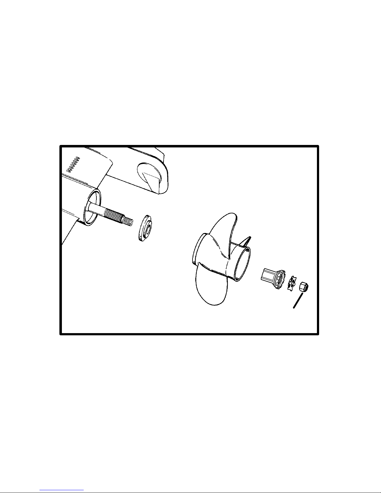
74
CA473
75492
2
Page 77
75
CA77
Propeller
WARNING
Avoid Injury: Remote Control must be in NEUTRAL and ignition key removed from switch before removing and/or installing propeller.
WARNING
Avoid Injury: Place a block of wood between anti-ventilation
plate and propeller to protect hands from propeller blades and
to prevent propeller from rotating when removing propeller
nut.
CAUTION
Avoid Injury: Periodically check propeller nut for tightness
during boating season. A minimum of 55 lbs. ft. (75 N
⋅m)
torque is required.
CA746
REMOVAL
1 Place wood block between propeller blade and anti-ventilation
plate to prevent rotation. Straighten bent tabs on tab washer.
2 Turn propeller shaft nut counterclockwise to remove nut.
3 Slide tab washer, spline washer, propeller and thrust hub off
propeller shaft.
CA79
REPAIR
Some damaged propellers can be repaired. See your dealer.
Page 78
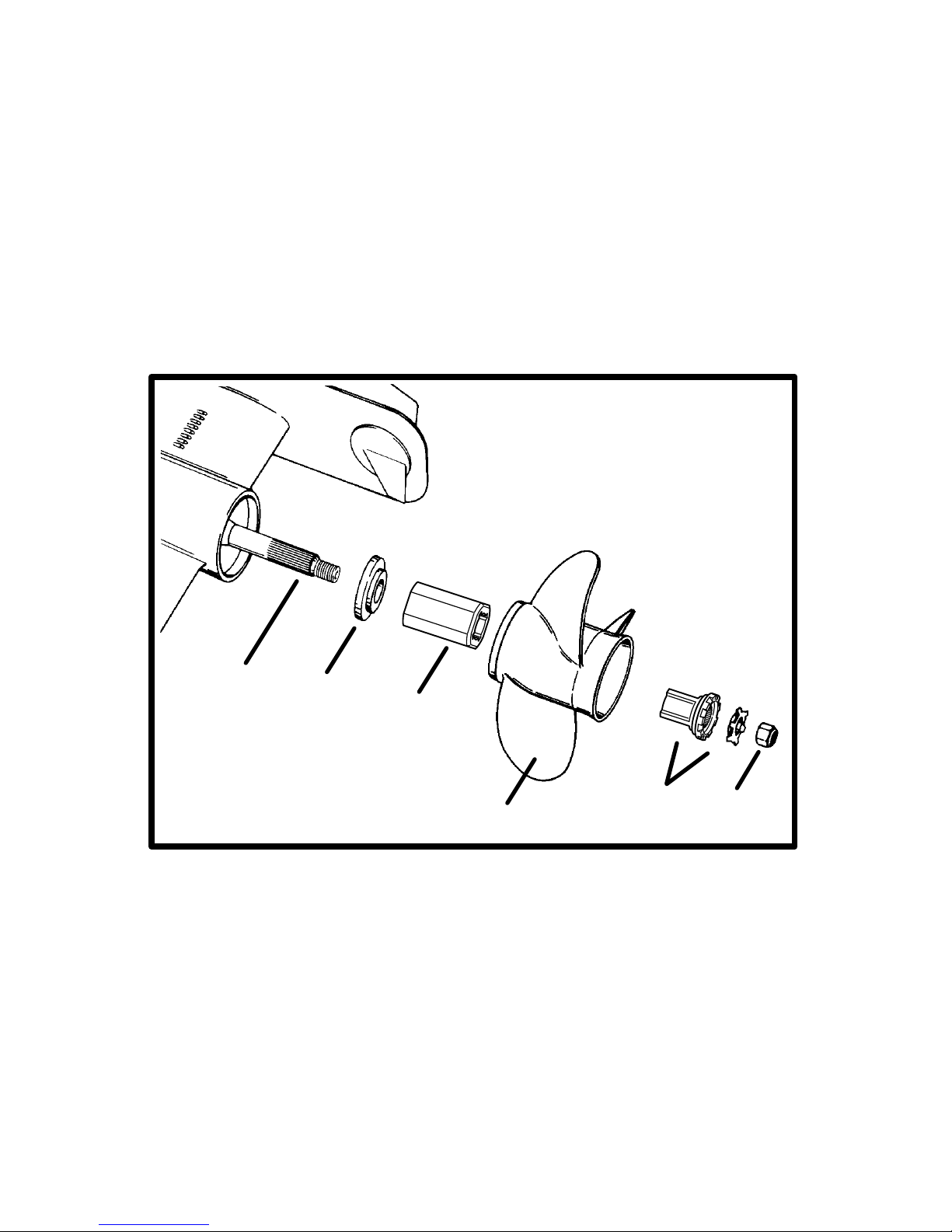
76
CA634
4
5
6
7
8
75492
9
Page 79

77
CA635
INSTALLATION
IMPORTANT: If reusing tab washer, carefully inspect tabs for
cracks or other damage. Replace tab washer if condition is
questionable.
4 Apply a liberal coat of one of the following Quicksilver lubricants
to propeller shaft: Anti-Corrosion Grease, Special Lubricant 101, or
2-4-C Marine Lubricant with Teflon.
5 Slide thrust hub onto propeller shaft, with stepped side toward
propeller hub.
6 Install Flo-Torque II Drive Hub into propeller.
NOTE: The drive sleeve is tapered and will slide fully into the propel-
ler as the nut is tightened and properly torqued.
7 Align splines and place propeller on propeller shaft.
8 Install drive sleeve adapter and locking tab washer.
9 Install propeller nut. T ighten nut securely. A minimum of 55 lbs. ft.
(75 N·m) torque is required. Bend three tabs on tab washer down into
grooves in spline washer. After first use, bend the three tabs straight,
retighten propeller nut to minimum 55 lbs. ft. torque (75 N·m). Bend
tabs back down into spline washer . Check propeller at least after 20
hours of operation. Do not operate with loose propeller.
Page 80

78
CA202
1
2
3
70565
71353
70564
Page 81

79
CA83
Flushing Cooling System
WARNING
When flushing, be certain the area around propeller is clear,
and no one is standing nearby. To avoid possible injury, remove propeller.
CAUTION
Do not run engine above 1500 RPM when flushing. Suction
created by seawater pickup pump may collapse flushing
hose, causing engine and/or drive unit to overheat.
CAUTION
Watch temperature gauge on dash to ensure that engine does
not overheat.
To prevent silt and/or salt buildup in cooling system, flush with
freshwater at specified intervals.
CB672
If flushing cooling system with boat in water, raise drive unit to
TRAILER position, install flushing attachment and lower drive unit to
full DOWN/IN position.
1 Install Quicksilver flushing attachment (or equivalent) over water
intake openings in gear housing.
2 Connect hose between flushing attachment and water tap.
3 With drive unit in normal operating position, partially open water
tap (about 1/2 maximum). Place remote control in NEUTRAL, idle
speed position and start engine. Operate engine at idle speed, in
NEUTRAL, for about 10 minutes or until discharge water is clear.
Stop engine, shut off water and remove flushing attachment.
Page 82
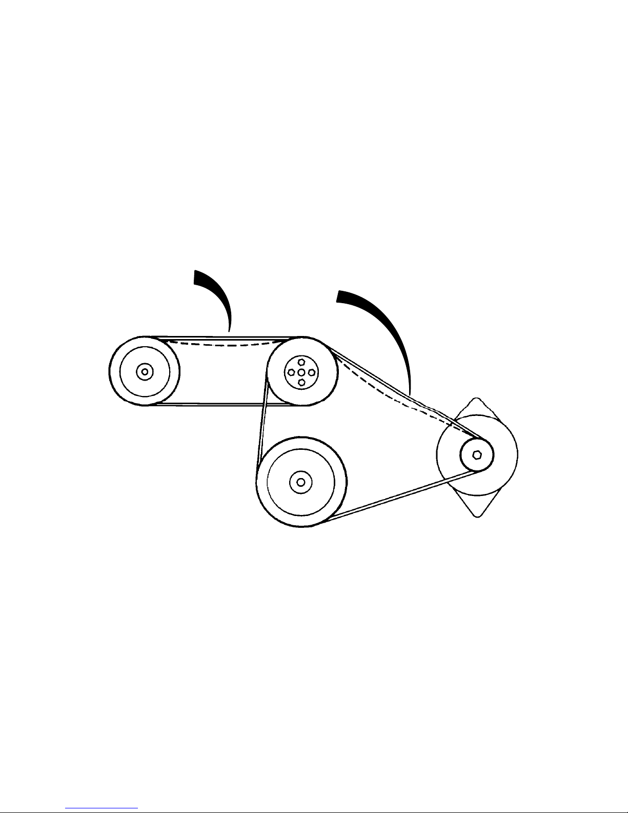
80
CA150
1
2
71428
Page 83

81
CA438
V-Belts (3.0L Model)
WARNING
Avoid possible serious injury. Make sure engine is shut off
and ignition key is removed before inspecting belt.
All drive belts must be periodically inspected for condition and
tension.
Perform the following inspections of alternator drive belt and power
steering pump drive belt (if so equipped).
If any drive belts need replacement or tension needs adjustment, see
your Authorized MerCruiser Dealer.
1 Alternator Drive Belt - Inspect drive belt for excessive wear or
damage.
Check belt tension by depressing upper strand of belt at point shown.
Belt should depress 1/2 in. (13mm).
2 Power Steering Pump Drive Belt (If So Equipped) - Inspect drive
belt for excessive wear or damage.
Check belt tension by depressing upper strand of belt at point shown.
Belt should depress 1/4 in. (6mm).
Page 84

82
CA436
2
3
A
B
C
D
E
A
B
C
D
E
A
1
1
Page 85

83
CA636
Serpentine Drive Belt (All Other Models)
WARNING
Avoid possible serious injury. Make sure engine is shut off
and ignition key is removed before inspecting belt.
Belt must be periodically inspected for condition and tension.
NOTE: Belt deflection is to be measured on the belt at the location
that has the longest distance between two pulleys. Normally this
location is between the power steering pump and belt adjustment
idler pulley on models without
closed cooling. This location is
between the power steering pump and alternator pulleys on models
with
closed cooling.
1 Check the tension of the serpentine drive belt. If there is more than
1/4 in. deflection on the drive belt, see your Authorized MerCruiser
Dealer to have the tension of the drive belt adjusted.
If any drive belts need replacement or tension needs adjustment, see
your Authorized MerCruiser Dealer.
2 Models without closed cooling
3 Models with closed cooling
A Idler Pulley
B Circulating Pump Pulley
C Crankshaft Pulley
D Alternator Pulley
E Power Steering Pulley
Page 86

84
CA204
71335
70578
70577
70576
70033
4
235
1
73919
Page 87

85
CA439
Corrosion And Corrosion Protection
Whenever two or more dissimilar metals (like those found on the
sterndrive) are submerged in a conductive solution, such as
saltwater, polluted water, or water with a high mineral content, a
chemical reaction takes place causing electrical current to flow
between metals. The electrical current flow causes the metal that is
most chemically active, or anodic, to erode. This is known as
galvanic corrosion and, if not controlled, it will in time cause the need
for replacement of power package components exposed to water.
IMPORTANT: Replace sacrificial anodes if eroded 50% or more.
1 Universal Anodic Plate - serves as a sacrificial anode.
2 Anodic Plate - serves as a sacrificial anode.
3 Block - Is mounted to underside of gimbal housing and serves as
a sacrificial anode.
4 MerCathode System (if so equipped) - Electrode assembly
replaces Anodic block.
System should be tested to ensure adequate output.
Test should be made where boat is moored, using Quicksilver
Reference Electrode and Test Meter. Contact your Authorized
MerCruiser Dealer to arrange for this test.
5 Anode Kit (if so equipped) - Mounted to boat transom. Acts as
a sacrificial anode.
Page 88
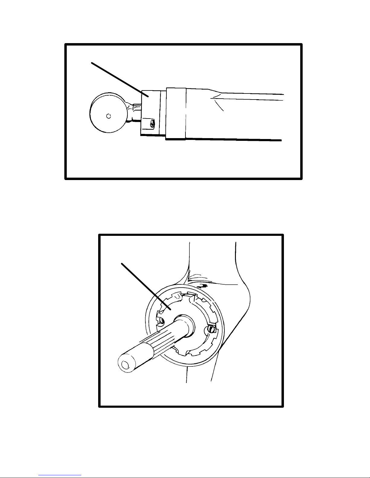
86
CA162
71958
71957
1
2
Page 89

87
CA440
1 Trim Cylinder Anodes - are mounted on each trim cylinder.
CA646
2 Bearing Carrier Anode - is located in front of the propeller,
between the front side of the propeller and the gear housing. Refer
to “Propeller” section in this manual for propeller removal and
installation.
Page 90

88
CA93
1
2
71176
3
Page 91

89
CA168
In addition to the corrosion protection devices, the following steps
should be taken to inhibit corrosion:
IMPORTANT: Corrosion damage that results from the improper
application of anti-fouling paint will not be covered by the
limited warranty.
1 Painting Boat Hull or Boat T ransom: Anti-fouling paint may be
applied to boat hull and boat transom
but you must observe the
following precautions:
IMPORTANT: DO NOT paint anodes or MerCathode System
reference electrode and anode, as this will render them
ineffective as galvanic corrosion inhibitors.
IMPORTANT: If anti-fouling protection is required for boat hull
or boat transom, copper or tin base paints, if not prohibited by
law, can be used. If using copper or tin based anti-fouling
paints, observe the following:
2 Avoid any electrical interconnection between the MerCruiser
Product, Anodic Blocks, or MerCathode System and the paint
by allowing a minimum of 1-1/2 in. (40mm) UNP AINTED area on
transom of the boat around these items.
3 Painting Drive Unit or Transom Assembly: Drive unit and
transom assembly should be painted with a good quality marine paint
or an anti-fouling paint that DOES NOT
contain copper, tin, or any
other material that could conduct electrical current. Do not paint drain
holes, anodes, MerCathode system, and items specified by boat
manufacturer.
4 Spray power package components on inside of boat every 2-3
weeks with Quicksilver Corrosion Guard to protect finish from dulling
and corrosion. External power package components may also be
sprayed.
5 All lubrication points, especially steering system, shift and throttle
linkages, should be kept well lubricated.
6 Flush cooling system periodically, preferably after each use.
Page 92
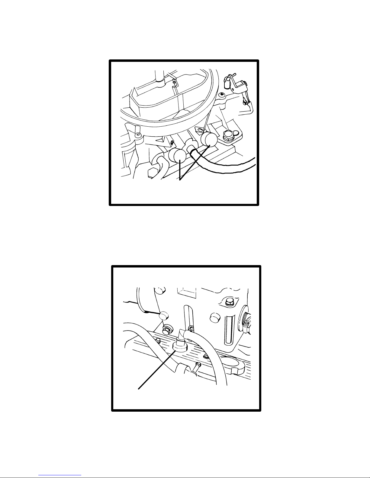
90
CA97
1
71925
71918
“SEE CAUTION”
Page 93
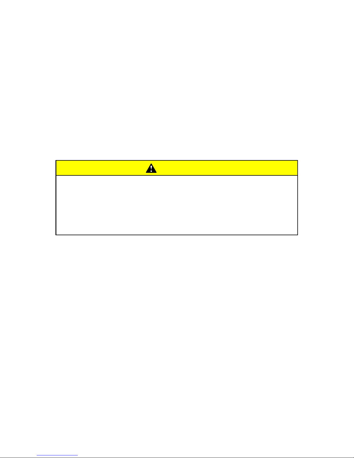
91
CA474
Emissions
(Europe Only)
CA399
The following information applies only to engines with a special
emissions kit installed. If the kit has been installed, your engine
complies with “Stage 1” Bodensee and Swiss Regulations.
CA398
Sealed Carburetor Mixture Screws
The carburetor on this engine has seals on the carburetor mixture
screws. These seals prevent adjustment of the fuel mixture settings.
CAUTION
Do not remove mixture screw seals and/or attempt to adjust
fuel mixture setting. Tampering with the mixture setting on
this engine could affect the exhaust emissions level, thus
voiding the emissions certification. These seals should only
be removed by an authorized dealer or emissions testing
agency.
CA99
Changing Positive Crankcase
Ventilation Valve (PCV)
This engine is equipped with a positive crankcase ventilation valve
(PCV). This valve should be changed every 100 hours of operation
or at least once a year, whichever occurs first.
1 Remove PCV valve from port valve cover . Disconnect it from t h e
hose and discard valve. Install new PCV valve in valve cover and
reconnect hose. Ensure valve is tightly seated in valve cover.
Use only MerCruiser replacement parts to ensure compliance with
emission regulations.
Page 94

92
CA637
75319
75324
71926
1
2A
2B
3
C
Page 95

93
CA100
Emissions Testing
Your engine is equipped with special design features and special
tuning to minimize the emission output from the engine. You should
follow:
• Recommended maintenance schedules particularly as to the
ignition system.
• Proper engine tuning procedures to ensure these features remain
in good operating order.
• Proper steps to maintain the engine within specifications.
CA638
Installing Test Probes
IMPORTANT: The testing dealer or agency will be equipped
with the appropriate test equipment and adapters for this
engine. The test probes should be installed as follows:
1 Remove plugs from both exhaust elbows.
2 Install exhaust elbow adapter fittings as follows.
A Apply Loctite Pipe Sealant with Teflon to threads that go into
elbow.
B Install fittings into elbows. Tighten fittings securely.
3 Insert exhaust probes (C) into fittings and tighten securely.
The testing agency will connect their adapters and test equipment to
the probes to conduct the test. Once the test is complete, they should
remove the test probes and fittings, apply Quicksilver Perfect Seal
to the threads of both plugs and reinstall them into elbows.
Page 96

94
CA478
Miscellaneous Maintenance
Battery
All lead acid batteries discharge when not in use. Recharge every 30
to 45 days, or when specific gravity drops below battery
manufacturer ’s specifications.
Refer to specific instructions and warnings accompanying your
battery. If this information is not available, observe the following
precautions when handling a battery.
WARNING
Avoid serious injury from gasoline fire or explosion. Do not
use jumper cables and a booster battery to start engine. Do
not recharge a weak battery in the boat. Remove battery and
recharge in a ventilated area away from fuel vapors, sparks or
flames.
WARNING
Batteries contain acid which can cause severe burns-Avoid
contact with skin, eyes and clothing. Batteries also produce
hydrogen and oxygen gases when being charged. This explosive gas escapes fill/vent cell caps and may form an explosive
atmosphere around the battery for several hours after it has
been charged. Sparks or flames can ignite the gas and cause
an explosion which may shatter the battery and could cause
blindness or other serious injury.
Safety glasses and rubber gloves are recommended when
handling batteries or filling with electrolyte. Hydrogen gases
that escape from the battery during charging are explosive.
When charging batteries, be sure battery compartment or area
where batteries are located, is well-vented. Battery electrolyte
is a corrosive acid and should be handled with care. If electrolyte is spilled or splashed on any part of the body, immediately
flush the exposed area with liberal amounts of water and obtain medical aid as soon as possible.
Page 97

95
CA104
Bottom Of Boat
To maintain maximum speed, the following conditions of the boat
bottom should be observed:
• Clean, free of barnacles and marine growth.
• Free of distortion, nearly flat where it contacts water.
• Straight and smooth, fore and aft.
ANTI-FOULING PAINTS
See Anti-Fouling Paint recommendations and related information on
previous pages.
IMPORTANT: Refer to CORROSION AND CORROSION
PROTECTION for additional information.
CA105
Inspection And Maintenance
Inspect power package often, and at regular intervals, to help
maintain its top operating performance, and correct potential
problems before they occur. The entire power package should be
checked carefully, including all accessible engine parts.
Check for loose, damaged or missing parts, hoses and clamps;
tighten or replace as required.
Check plug leads and electrical leads for damage.
Remove and inspect propeller . If badly nicked, bent or cracked, see
your dealer.
Repair nicks and corrosion damage on power package exterior
finish. Use Quicksilver spray paints - see your Authorized MerCruiser
Dealer.
Page 98

96
CA639
Cold Weather Or Extended Storage
Power Package Lay Up
IMPORTANT: MerCruiser strongly recommends that this
service should be performed by an Authorized MerCruiser
Dealer. Damage caused by freezing IS NOT
covered by the
MerCruiser Limited Warranty.
CA115
Battery Winter Storage
Follow battery manufacturer’s instructions for storage.
CA645
Do-It-Yourself Maintenance
If you desire to perform your own maintenance, contact an
Authorized MerCruiser Dealer to obtain a “Maintenance Procedures
Manual.” Refer to the Do-It-Yourself Maintenance Suggestions at the
front of the manual for additional information.
Page 99

97
CA116
Power Package Recommissioning
WARNING
To prevent possible injury or damage to equipment, do not install battery until all maintenance has been performed on engine.
1 Check that all cooling system hoses are connected properly and
hose clamps are tight.
CAUTION
When installing battery, be sure to connect NEGATIVE (–) battery cable to NEGATIVE (–) battery terminal and POSITIVE (+)
battery cable to POSITIVE (+) battery terminal. If battery cables
are reversed, electrical system damage will result.
2 Install fully-charged battery. Clean battery cable clamps and
terminals and reconnect cables (see CAUTION listed above).
Tighten each cable clamp securely when connecting.
3 Coat terminal connections with a battery terminal anti-corrosion
agent.
4 Perform all checks in OPERATION CHART in the BEFORE
STARTING column.
CAUTION
Refer to FLUSHING COOLING SYSTEM before starting engine.
5 Start engine and closely observe instrumentation to make sure
that all systems are functioning correctly.
6 Carefully inspect engine for fuel, oil, fluid, water and exhaust
leaks.
7 Check steering system, shift and throttle control for proper
operation.
8 Check fuel pump sight tube (if so equipped) for evidence of fuel
(indicating a ruptured fuel pump diaphragm).
Page 100

98
CA442
Troubleshooting
Starter Motor Will Not Crank Engine, Or Cranks
Slow
Possible Cause Remedy
Battery switch turned off. Turn switch on.
Remote control not in neutral
position.
Position control lever in neutral.
Open circuit breaker or blown
fuse.
Check and reset circuit breaker
or replace fuse.
Loose or dirty electrical
connections or damaged
wiring.
Check all electrical connections
and wires (especially battery
cables). Clean and tighten
faulty connection.
Bad battery. Test and replace if bad.
 Loading...