

Page 1
IMPORTANT
INFORMATION
1
D
OUTBOARD INSTALLATION
Page 2

Table of Contents
Page
Determining Recommended Outboard
Mounting Height 1D-1. . . . . . . . . . . . . . . . . . . . . . . . . . . . .
Notice to Installer and Owner 1D-2. . . . . . . . . . . . . . . . . .
Boat Horsepower Capacity 1D-2. . . . . . . . . . . . . . . . .
Outboard Remote Control 1D-2. . . . . . . . . . . . . . . . . .
Selecting Accessories For The Outboard 1D-2. . . . .
Selecting Steering Cables and Remote Control
Cables 1D-2. . . . . . . . . . . . . . . . . . . . . . . . . . . . . . . . . . .
Locate Center line Of The Outboard 1D-3. . . . . . . . .
Drilling Outboard Mounting Holes 1D-3. . . . . . . . . . . .
Lifting Outboard 1D-4. . . . . . . . . . . . . . . . . . . . . . . . . . .
Fastening Outboard To The Transom 1D-4. . . . . . . .
Single Steering Cable and Steering Link
Rod Installation 1D-5. . . . . . . . . . . . . . . . . . . . . . . . . . . . . .
Installing Ride Guide Steering Cable to the
Outboard 1D-5. . . . . . . . . . . . . . . . . . . . . . . . . . . . . . . . .
Steering Link Rod Installation 1D-5. . . . . . . . . . . . . . .
Co-Pilot Installation (Tiller Handle models) 1D-6. . . . . . .
Remote Control Installation 1D-7. . . . . . . . . . . . . . . . . . . .
Required Side Mount Remote Control or Ignition
Key Switch Assembly 1D-7. . . . . . . . . . . . . . . . . . . . . . . . .
Boats Equipped with Side Mount
Remote Control 1D-7. . . . . . . . . . . . . . . . . . . . . . . . . . .
Boats Equipped with Panel Or Console Mount
Remote Control 1D-7. . . . . . . . . . . . . . . . . . . . . . . . . . .
Connecting Remote Wiring Harness to the Engine 1D-7
Shift and Throttle Cable Installation to the Outboard1D-8
Shift Cable Installation 1D-8. . . . . . . . . . . . . . . . . . . . .
Throttle Cable Installation 1D-9. . . . . . . . . . . . . . . . . .
Battery Connections 1D-10. . . . . . . . . . . . . . . . . . . . . . . . .
Set Up Instructions For Oil Injection System 1D-10. . . .
Filling The Oil Injection System 1D-10. . . . . . . . . . . . .
Bleeding Air From The Oil Injection System 1D-11. .
Adjusting The Oil Injection Pump 1D-11. . . . . . . . . . .
Trim Tab Adjustment 1D-12. . . . . . . . . . . . . . . . . . . . . . . . .
90-830234R3 DECEMBER 19971D-0 - IMPORTANT INFORMATION
Page 3
Notice to Installer and Owner
Outboard Remote Control
This manual as well as safety labels posted on the
outboard use the following safety alerts to draw your
attention to special safety instructions that should be
followed.
W ARNING
WARNING – Hazards or unsafe practices which
COULD result in severe personal injury or death.
CAUTION
CAUTION – Hazards or unsafe practices which could
result in minor injury or product or property damage.
Boat Horsepower Capacity
U.S. COAST GUARD CAPACITY
MAXIMUM HORSEPOWER XXX
MAXIMUM PERSON
CAPACITY (POUNDS) XXX
MAXIMUM WEIGHT
CAPACITY XXX
Do not overpower or overload your boat. Most boats
will carry a required capacity plate indicating the
maximum acceptable power and load as determined
by the manufacturer following certain federal guidelines. If in doubt, contact your dealer or the boat manufacturer.
W ARNING
Using an outboard that exceeds the maximum
horsepower limit of a boat can: 1. cause loss of
boat control 2. place too much weight at the transom altering the designed flotation characteristics of the boat or 3. cause the boat to break apart
particularly around the transom area. Overpowering a boat can result in serious injury , death, or
boat damage.
The remote control connected to your outboard must
be equipped with a start-in-gear protection device.
This prevents the engine from starting when the outboard is in gear.
WARNING
Avoid serious injury or death from a sudden unexpected acceleration when starting your engine. The design of this outboard requires that
the remote control used with it must have a built
in start-in-gear protection device.
Selecting Accessories For
The Outboard
Genuine Mercury Marine Quicksilver Accessories
have been specifically designed and tested for your
outboard.
Mercury Marine Quicksilver accessories are available from Mercury Marine dealers.
Some accessories not manufactured or sold by Mercury Marine are not designed to be safely used with
your outboard or outboard operating system. Acquire
and read the installation, operation, and maintenance manuals for all your selected accessories.
WARNING
Check with your dealer before installation of accessories. The misuse of acceptable accessories or the use of unacceptable accessories can
result in serious injury , death, or product failure.
Selecting Steering Cables
and Remote Control Cables
Refer to “Quicksilver Accessories Guide” to determine correct length of steering cables and remote
control cables.
90-830234R3 DECEMBER 1997 IMPORTANT INFORMATION - 1D-1
IMPORT ANT : Steering cables and remote control
cables must be the correct length. Sharp bends
on too-short cables result in “kinks”; too-long
cables require unnecessary bends and/or loops.
Both conditions place extra stress on the cables.
Page 4
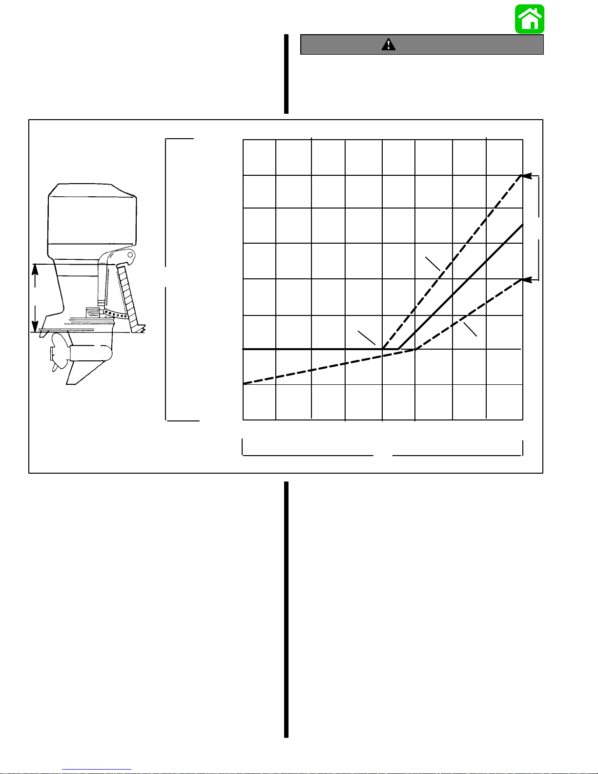
Determining Recommended
WARNING
Outboard Mounting Height
26 in.
(660m
m)
25 in.
(635m
m)
24 in.
(609m
m)
23 in.
(584m
m)
e
e
22 in.
(560m
m)
21 in.
(533m
m)
20 in.
(508m
m)
19 in.
(482m
m)
Boat instability can occur at high speeds by
installing engine at the wrong transom height.
Contact the boat manufacturer for their recommendations for a specific engine installation.
b
c
a
d
10
NOTE: Add 5 in. (127mm) for XL models and 10 in.
(254mm) for XXL models to listed outboard mounting
height.
a. This solid line is recommended to determine
the outboard mounting height.
IMPORTANT: Increasing the height of outboard
generally will provide the following: 1) Less
steering torque, 2) more top speed, 3) greater
boat stability , but, 4) will cause more prop “break
loose” which may be particularly noticeable
when planing off or with heavy load.
b. These broken lines represent the extremes of
known successful outboard mounting height
dimensions.
c. This line may be preferred to determine out-
board mounting height dimension, if maximum speed is the only objective.
20 30 40 50 60 70 80
f
d. This line may be preferred to determine out-
board mounting height dimension for dual
outboard installation.
e. Outboard mounting height (height of out-
board transom brackets from bottom of boat
transom). For heights over 22 in. (560mm), a
propeller, that is specifically designed for surfacing operation, such as the “Laser” and “Mirage” series, usually are preferred.
f. Maximum boat speed anticipated.
90-830234R3 DECEMBER 19971D-2 - IMPORTANT INFORMATION
Page 5
Locating Center Line Of The
Outboard
Locate (and mark with pencil) the vertical centerline
(a) of boat transom.
BA
a
DC
a - Centerline of Transom
NOTE: When drilling into a fiberglass boat, place
masking tape directly onto boat where mounting
holes will be drilled to help prevent fiberglass from
chipping.
Use a 17/32 inch (13.5mm) diameter drill bit and drill
4 mounting holes perpendicular to and thru transom.
IMPORTANT: If using “Transom Drilling Fixture”
(part number 91–98234A2), use drill guide holes
marked “A” when drilling outboard mounting
holes.
NOTE: Dimensions “A” & “B” and “C” & “D” are equal
length.
IMPORT ANT : During installation of dual outboards,
the following is recommended. A minimum of 221/2
inches (570mm) centerline to centerline width is recommended. This is required to alleviate cowling interference during lock to lock turns if one outboard
would be in the full tilt position, while the other outboard(s) are in the vertical running position.
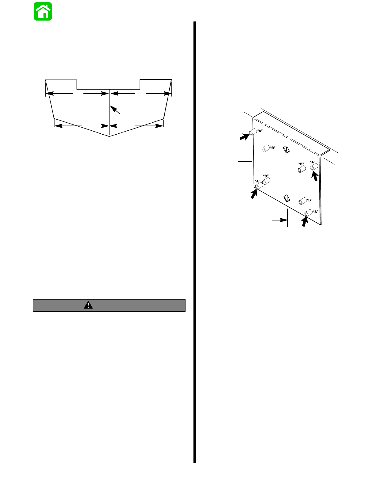
Drilling Outboard Mounting Holes
IMPORT ANT : Before drilling any mounting holes,
carefully read “Determining Recommended Outboard Mounting Height,” preceding. There is a
3/4 inch (19mm) difference between outboard
mounting holes in transom brackets.
WARNING
DO NOT, under any circumstances, allow upper
outboard mounting bolts to be closer than 1 inch
(25.4mm) from top of boat transom. Upper
mounting bolts must never be installed thru
shims.
b
a
a – Centerline of Transom
b – Transom Drilling Fixture (91–98234A2)
90-830234R3 DECEMBER 1997 IMPORTANT INFORMATION - 1D-3
Page 6

Lifting Outboard
Installing Outboard To Boat
WARNING
Verify that the lifting ring is threaded into the flywheel a minimum of 5 turns and that hoist has a
maximum lift capacity over 500 lbs. (227 kg) BEFORE lifting outboard.
1. Electric Start Models – Remove plastic cap from
center of flywheel. Thread lifting ring into flywheel
hub a minimum of 5 turns. Replace plastic cap after installation.
b
a
Transom
IMPORT ANT : If boat is equipped with thru tilt tube
steering, steering cable end must be installed
into tilt tube of outboard (port outboard only for
dual outboard installations) before securing outboard to transom. Refer to ”Steering Cable and
Steering Link Rod Installation” following.
Refer to “Determining Recommended Outboard Motor Mounting Height”, preceding and position outboard on boat transom, to align mounting holes in
transom bracket that will place the outboard nearest
to the recommended mounting height.
CAUTION
Marine sealer must be used on shanks bolts to
make a water-tight installation.
IMPORT ANT: DO NOT use an impact driver when
tightening transom bolts.
Apply marine sealer to shanks of mounting bolts (not
threads) and secure outboard to transom with 4 bolts,
flat washers and locknuts, as shown. Be sure that installation is water-tight.
a - Lifting Ring
b - Plastic Cap – Replace After Installation
2. Manual Start Models – Use lifting eye on engine
and lift outboard on boat transom.
WARNING
Before operation, the outboard must be correctly
installed with four mounting bolts shown. Failure
to correctly fasten outboard could result in outboard ejecting off boat transom causing serious
injury, death, or property damage.
a
b
c
b
c
a - 1/2 Inch Diameter Bolts
b - Flat Washers
c - Locknuts
a
90-830234R3 DECEMBER 19971D-4 - IMPORTANT INFORMATION
Page 7

Single Steering Cable and
Steering Link Rod Installation
Steering Link Rod
Installation
NOTE: These instructions are for single cable–single
outboard installations. Instructions for mounting dual
engines are included with the applicable dual engine
attaching kit. Refer to “Quicksilver Accessories
Guide” to determine correct kit.
Refer to “Quicksilver Accessories Guide” to determine correct length of steering cable.
IMPORTANT: Steering cable must be correct
length. Sharp bends on too-short of a cable result in “kinks;” too-long of a cable require unnecessary bends and/or loops. Both conditions
place extra stress on the cable.
Install steering mount and steering wheel in accordance with installation instructions that accompany
each.
Installing Ride Guide Steering Cable
To The Outboard
IMPORTANT: Before installing steering cable in
tilt tube, lubricate entire cable end with Quicksilver 2-4-C Marine Lubricant.
IMPORT ANT: The steering link rod that connects
the steering cable to the engine must be fastened
using special washer head bolt (“a” – Part Number 10-14000) and self locking nuts (“b”& “c”–
Part Number 11-34863). These locknuts must
never be replaced with common nuts (non locking) as they will work loose and vibrate off freeing the link rod to disengage.
WARNING
Disengagement of a steering link rod can result
in the boat taking a full, sudden, sharp turn. This
potentially violent action can cause occupants to
be thrown overboard exposing them to serious
injury or death.
3. Assemble steering link rod to steering cable with
two flat washers (d) and nylon insert locknut (“b”
– Part Number 1 1-34863). Tighten locknut (b) until it seats, then back nut off 1/4 turn.
4. Assemble steering link rod to engine with special
washer head bolt (“a” – Part Number 10-14000)
and nylon insert locknut (“c”– Part Number
11-34863). First torque bolt (a) to 20 lb. ft. (27.0
N·m), then torque locknut (c) to 20 lb. ft. (27.0
N·m).
NOTE: Ride Guide steering cable is lubricated at the
factory and requires no additional lubrication at initial
installation.
1. Lubricate seal (a) inside of outboard tilt tube and
entire cable end (b) with Quicksilver 2-4-C Marine Lubricant.
2. Insert steering cable end thru outboard tilt tube
and secure steering cable to tilt tube with steering
cable attaching nut (c), as shown. Torque nut to
35 lb. ft. (47.5 N·m).
95
c
95
a
b
a
d
b
c
WARNING
After installation is complete (and before operating outboard), check that boat will turn right
when steering wheel is turned right and that boat
will turn left when steering wheel is turned left.
Check steering thru full range (left and right) and
at all tilt angles to assure interference-free movement.
95
90-830234R3 DECEMBER 1997 IMPORTANT INFORMATION - 1D-5
2-4-C With Teflon (92-825407A12)
Page 8

Co-Pilot Installation (Tiller
Handle models)
WARNING
Avoid possible serious injury or death from loss
of boat control. The Co-pilot assembly must be
installed and adjusted to maintain sufficient
steering friction to prevent the outboard from
steering into a full turn if the tiller handle is released.
1. Thread the friction collar (a) onto the starboard
side of the tilt tube. Tighten securely and position
the adjustment knob toward front of outboard.
2. Insert pilot rod (b) into the friction collar.
a
IMPORT ANT : The co-pilot link rod (c) must be fastened using self locking nylon insert locknuts
(“f”& “g”– Part Number 11-45592).These locknuts must never be replaced with common nuts
(non locking) as they will work loose and vibrate
off freeing the link rod to disengage.
WARNING
Disengagement of the co-pilot link rod can result
in the boat taking a full, sudden, sharp turn. This
potentially violent action can cause occupants to
be thrown overboard exposing them to serious
injury or death.
3. Lubricate both ends of the link rod with Quicksilver 2-4-C w/Teflon Marine Lubricant. Install link
rod between the tiller handle mount and pilot rod
as shown.
b
f
e
d
c
e
g
c - Co-Pilot Link Rod
d - Spacer (Hidden) - Place in the Upper Mounting Hole
For The Link Rod.
e - Flat Washer
f - Locknut - Torque to 120 lb. in. (13.6 N·m)
g - Locknut - Tighten Until it Seats; DO NOT exceed 120 lb.
in. (13.6 N·m), Then Back Off The Locknut 1/4 Turn.
90-830234R3 DECEMBER 19971D-6 - IMPORTANT INFORMATION
Page 9

Remote Control Installation
Shift and Throttle Cable
Refer to “Quicksilver Accessories Guide” to determine correct length of remote control cables.
IMPORT ANT : Remote control cables must be correct length. Sharp bends on too-short cables result in “kinks;” too-long cables require unnecessary bends and/or loops. Both conditions place
extra stress on the cables.
IMPORTANT: Install control cables to remote
control and mount remote control BEFORE attaching control cables to engine. Refer to installation instructions included with remote control.
Required Side Mount
Remote Control or Ignition
Key Switch Assembly
Boats Equipped with Side Mount
Remote Control
A Quicksilver Commander 2000 series Side Mount
Remote Control equipped with a warning horn must
be used with this outboard. This warning horn is necessary for the engine warning system.
Installation To The Outboard
Install the shift cable and throttle cable into the remote control and mount the remote control following
instructions which are provided the remote control.
NOTE: Install the shift cable before the throttle cable.
The shift cable is the first cable to move when the remote control handle is moved into gear.
Shift Cable Installation
1. Pull up the cowl seal and remove the port side
rubber grommet (a).
a
2. Position the remote control and outboard into
neutral.
3. Slide shift actuator (b) toward the rear of engine
(reverse gear) until resistance is felt. Measure
distance (c) between mounting stud and barrel
retainer.
a
a -Warning Horn
Boats Equipped with Panel Or
Console Mount Remote Control
A Quicksilver Ignition Key/Choke Assembly
equipped with a warning horn must be used with this
engine. This warning horn is necessary for the engine warning system.
a
4. Push the cable end (d) in (towards cable barrel)
until resistance is felt. Adjust the cable barrel (e)
to attain distance (c).
e
d
c
b
a - Warning Horn
90-830234R3 DECEMBER 1997 IMPORTANT INFORMATION - 1D-7
Page 10

5. Place cable barrel into retainer and fasten the
cable end to mounting stud with nylon washer (f)
and locknut (g). Tighten locknut against the nylon
washer, then back-off the locknut 1/4 turn.
6. Check shift cable adjustments as follows:
a. With remote control in forward the propshaft
should lock solidly in gear. If it does not, adjust the cable barrel closer to the cable end
guide.
3. Adjust throttle cable barrel (b) so the barrel will be
able to slip into the retainer when the cable end
is on the mounting stud and there is a slight preload against the stop.
4. Check preload on throttle cable by placing a thin
piece of paper between adjustment screw and
stop. Preload is correct when the paper can be removed without tearing, but has some drag in it.
Readjust cable barrel if necessary.
5. Place the throttle cable barrel into the top retainer
hole and the cable end on the cable mounting
stud. Fasten throttle cable to the mounting stud
with nylon washer (c) and locknut (d). Tighten
locknut against the nylon washer, then back-off
the locknut 1/4 turn.
6. Lock the cable barrels in-place with cable latch
(e).
b. Shift remote control into neutral. The prop-
shaft should turn freely without drag. If not,
adjust the barrel away from the cable end
guide. Repeat steps a and b.
c. Shift remote control into reverse while turning
propeller. The propshaft should lock solidly in
gear. If not, adjust the barrel away from the
cable end guide. Repeat steps a thru c.
d. Return remote control handle to neutral. The
propeller should turn freely without drag. If
not, adjust the barrel closer to the cable end
guide. Repeat steps a thru d.
Throttle Cable Installation
NOTE: Attach Shift cable to engine prior to attaching
throttle cable.
1. Position the remote control handle into neutral
detent.
2. Position adjustment screw (a) against the stop.
a
b
d
c
e
7. Lubricate the port side rubber grommet and reinstall into cowl. Slip the grommet over the control
cables. Push the cowl seal back into place.
90-830234R3 DECEMBER 19971D-8 - IMPORTANT INFORMATION
Page 11

NOTE: The rubber grommet has to be lubricated to
ease installation.
f
f
f – Lubricant
Connecting Remote Wiring
Harness To The Engine
1. Pull up the cowl seal (a) and remove the starboard side rubber grommet (b).
b
a
2. Take hold of the engine connector (c) and install
the remote wiring harness plug (d). Connect
additional wire leads (if equipped) as shown.
NOTE: The rubber grommet can to be lubricated to
ease installation.
90-830234R3 DECEMBER 1997 IMPORTANT INFORMATION - 1D-9
c
d
Page 12

3. Push the connector and plug into the holder (e).
e
Battery Connections
CAUTION
For dual outboard installations, the black (–) battery cable of each engines starter motor ground
circuit, MUST BE connected to each other by a
common circuit (cable) capable of carrying the
starting current of each engine’s starter motor.
[i.e. A locally obtained battery cable connected
between the negative (–) terminal of each outboards cranking battery].
CAUTION
Failure to observe correct polarity when connecting battery cables to battery, will result in
damage to the charging system.
4. Insert the battery cables and remote wiring harness into the rubber grommet. Reinstall the starboard side rubber grommet into the cowl. Push
the cowl seal back in place.
1. Connect battery cables (from engine) to battery.
Connect red battery cable to positive terminal
and black battery cable to negative (–) battery
terminal.
Set Up Instructions For Oil
Injection System
CAUTION
Oil injected engines additionally , must be run on
a 50:1 gasoline/oil mixture during the engine
break-in period. Refer to engine break-in procedure in the Operation & Maintenance Manual.
CAUTION
If an electric fuel pump is to be used on engines
with oil injection, the fuel pressure at the engine
must not exceed 4 psig. If necessary, install a
pressure regulator between electrical fuel pump
and engine and set at 4 psig maximum.
90-830234R3 DECEMBER 19971D-10 - IMPORTANT INFORMATION
Page 13

Filling The Oil Injection System
1. Open the cowl cap (a). Turn the oil fill cap (b) to
the left and remove.
a
Bleeding Air From The Oil Injection
System
IMPORT ANT : If air exists in either the oil pump inlet hose (a) or oil pump outlet hose (b), the air
MUST BE bled from the hose(s) or engine damage may occur.
BLEEDING AIR FROM THE OIL PUMP INLET
HOSE
b
2. Use the dipstick (c) to check oil level.
3. Hook the dipstick (d) on the tank during filling.
c
d
4. Slowly fill the oil tank with the specified oil. Do Not
overfill – add only enough oil to bring the oil level
up to the bottom of the fill neck (e).
Note:The oil tank capacity for three cylinder models
is 3.2 qt. (3.0 liters) and four cylinder models is 5.13
qt. (4.9 liters).
5. Install oil filler cap (b) and re-tighten. Reinstall the
cowl cap.
1. With the engine not running, place a shop towel
below the oil pump.
2. Loosen bleed screw (c) four turns and allow oil to
flow out of the bleed hole until no air bubbles exist
in the inlet hose (a).
BLEEDING AIR FROM THE OIL PUMP OUTLET
HOSE
3. If any air bubbles are present in the outlet hose
(b), they can be purged from the hose by removing link rod (d) from the oil pump and rotating the
pump arm (e) full clockwise while operating engine at 1000 to 1500 RPM.
b
c
e
b
FULL
90-830234R3 DECEMBER 1997 IMPORTANT INFORMATION - 1D-11
a
d
e
Page 14

Adjusting The Oil Injection Pump
Trim Tab Adjustment
When carburetor linkage is at idle position, alignment
mark (a) on oil injection arm should be in-line with
mark (b) on pump as shown. If necessary , adjust link
rod (c).
b
Propeller steering torque will cause your boat to pull
in one direction. This steering torque is a normal thing
that results from your outboard not being trimmed so
the propeller shaft is parallel to the water surface.
The trim tab can help to compensate for this steering
torque in many cases and can be adjusted within limits to reduce any unequal steering effort.
NOTE: Trim tab adjustment will have little effect reducing steering torque if the outboard is installed with
the anti-ventilation plate approximately 2 inches
(50mm) or more above the boat bottom.
Operate your boat at normal cruising speed, trimmed
to desired position. Turn your boat left and right and
note the direction the boat turns more easily.
If adjustment is necessary, loosen trim tab bolt and
make small adjustments at a time. If the boat turns
more easily to the left, move the trailing edge of trim
tab to the left. If the boat turns more easily to the right
move the trailing edge of trim tab to the right. Retighten bolt and retest.
c
a
90-830234R3 DECEMBER 19971D-12 - IMPORTANT INFORMATION
 Loading...