

Page 1

2002, Mercury Marine
Tow Sports / Inboard MPI Models
90Ć864197020 302
Page 2
0001
Identification Record
PLEASE RECORD THE FOLLOWING INFORMATION:
1.
Engine Model and Horsepower
Engine Serial Number
2.
Transom Assembly Serial Number
(Sterndrive)
Gear Ratio Sterndrive Unit Serial
Number
3.
Transmission Model (Inboard)
Gear Ratio Transmission Serial
Number
4.
Propeller Number
Pitch Diameter
5.
Hull Identification Number (HIN)
Purchase Date
6.
Boat Manufacturer
Boat Model Length
7.
Exhaust Gas Emissions Certificate Number (Europe Only)
The serial numbers are the manufacturer’s keys to numerous engineering details which apply
to your Mercury MerCruiser
power package. When contacting your Authorized Mercury
MerCruiser Dealer about service, always specify model and serial numbers.
The description and specifications contained herein were in effect at the time this guide was
approved for printing. Mercury Marine, whose policy is one of continuous improvement,
reserves the right to discontinue models at any time, or to change specifications or designs,
without notice and without incurring obligation.
Mercury Marine, Fond du Lac, Wisconsin, U.S.A. Printed in U.S.A.
2002, Mercury Marine
The following are registered trademarks of Brunswick Corporation: AutoBlend, Jet-Prop,
Mariner, Merc, MerCathode, MerCruiser, Mercury, Mercury Marine, Quicksilver, RideGuide,
Thruster and Mercury Precision Parts.
7
1
3
71452
Page 3

0002
Welcome!
You have selected one of the finest marine power packages available. It incorporates
numerous design features to assure operating ease and durability.
With proper care and maintenance, you will thoroughly enjoy using this product for many
boating seasons. To ensure maximum performance and carefree use, we ask that you
thoroughly read this manual.
The Operation, Maintenance and Warranty Manual contains specific instructions for using
and maintaining your product. We suggest that this manual remain with the product for ready
reference whenever you are on the water.
Thank you for purchasing one of our Mercury MerCruiser products. We sincerely hope your
boating will be pleasant!
Consumer Affairs Department
0003
Warranty Message
The product you have purchased comes with a limited warranty from Mercury Marine; the
terms of the warranty are set forth in the Warranty Sections of this manual. The warranty
statement contains a description of what is covered, what is not covered, the duration of
coverage, how to best obtain warranty coverage, important disclaimers and limitations of
damages and other related information. Please review this important information.
Page 4
0004
Read This Manual Thoroughly
IF YOU DON’T UNDERSTAND ANY PORTION, CONTACT YOUR DEALER FOR A
DEMONSTRATION OF ACTUAL STARTING AND OPERATING PROCEDURES.
NOTICE
Throughout this publication, and on your power package, WARNINGS and CAUTIONS,
accompanied by the International Hazard Symbol
to special instructions concerning a particular service or operation that may be hazardous if
performed incorrectly or carelessly. Observe them carefully.
These Safety Alerts alone cannot eliminate the hazards that they signal. Strict compliance
with these special instructions while performing the service, plus common sense operation,
are major accident prevention measures.
WARNING - Hazards or unsafe practices which could result in severe personal injury
or death.
!
WARNING
CAUTION
, may be used to alert the installer/user
CAUTION - Hazards or unsafe practices which could result in minor personal injury
or product or property damage.
IMPORTANT: - Indicates information or instructions that are necessary for proper
operation and/or maintenance.
WARNING
The operator (driver) is responsible for the correct and safe operation of the boat, the
equipment aboard and the safety of all occupants aboard. We strongly recommend
that the operator read this Operation, Maintenance and Warranty Manual and
thoroughly understand the operational instructions for the power package and all
related accessories before the boat is used.
Page 5

WARRANTY
Warranty Information 2. . . . . . . . . . . . . . . .
Owner Warranty Registration 2. . . . . . .
International Owner Registration 3. . . .
Warranty Policies 4. . . . . . . . . . . . . . . . . . .
Mercury MerCruiser One Year
Limited Warranty
(Gasoline Fueled Products Only) 4. . .
GETTING TO KNOW YOUR POWER PACKAGE
Features And Controls 12. . . . . . . . . . . . . . .
Lanyard Stop Switch 12. . . . . . . . . . . . . .
Instrumentation 14. . . . . . . . . . . . . . . . . . .
Remote Controls 15. . . . . . . . . . . . . . . . .
Electrical System Overload Protection 18
Audio Warning System 19. . . . . . . . . . . .
Engine Guardian Strategy 20. . . . . . . . .
ON THE WATER
Safe Boating Suggestions 24. . . . . . . . . . . .
Be Alert To Carbon Monoxide
Poisoning 26. . . . . . . . . . . . . . . . . . . . . . . .
Basic Boat Operation 28. . . . . . . . . . . . . . . .
Launching And Boat Operation Care 28
Starting And Stopping The Engine 29. .
Freezing Temperature Operation 29. . .
Drain Plug and Bilge Pump 29. . . . . . . .
Protecting People In The Water 30. . . . . . .
While You Are Cruising 30. . . . . . . . . . . .
While Boat Is Stationary 30. . . . . . . . . . .
High-Speed And High-Performance
Boat Operation 30. . . . . . . . . . . . . . . . . . . . . .
Wave And Wake Jumping 31. . . . . . . . . . . .
3 Year Limited Warranty
Against Corrosion (Worldwide) 6. . . . .
Transferable Warranty 8. . . . . . . . . . . . . . .
Direct Sale By Owner 8. . . . . . . . . . . . .
Mercury Product Protection Plan 8. . . . . .
United States And Canada Only 8. . . .
Impact With Underwater Hazards 32. . . . .
Conditions Affecting Operation 33. . . . . . . .
Weight Distribution (Passengers
And Gear) Inside The Boat 33. . . . . . . .
Bottom Of Boat 33. . . . . . . . . . . . . . . . . . .
Cavitation 33. . . . . . . . . . . . . . . . . . . . . . .
Elevation And Climate 34. . . . . . . . . . . . .
Propeller Selection 34. . . . . . . . . . . . . . . .
Getting Started 35. . . . . . . . . . . . . . . . . . . . . .
20-Hour Break-In Period 35. . . . . . . . . . .
After Break-In Period 35. . . . . . . . . . . . . .
End of First Season Checkup 35. . . . . .
90-864197020 MARCH 2002 Page i
Page 6

SPECIFICATIONS AND MAINTENANCE
Specifications 38. . . . . . . . . . . . . . . . . . . . . . .
Fuel Recommendations 38. . . . . . . . . . .
Engine Oil 40. . . . . . . . . . . . . . . . . . . . . . .
Engine Specifications 41. . . . . . . . . . . . .
Fluid Specifications 42. . . . . . . . . . . . . . .
Owner/Operator Responsibilities 43. . . . . .
Dealer Responsibilities 43. . . . . . . . . . . . . . .
Maintenance 44. . . . . . . . . . . . . . . . . . . . . . . .
Do-It-Yourself Maintenance
Suggestions 45. . . . . . . . . . . . . . . . . . . . .
Inspection 46. . . . . . . . . . . . . . . . . . . . . . .
Inboard Maintenance Chart 46. . . . . . . .
Maintenance Record 49. . . . . . . . . . . . . .
Engine Oil 50. . . . . . . . . . . . . . . . . . . . . . . . . .
Checking 50. . . . . . . . . . . . . . . . . . . . . . . .
Filling 51. . . . . . . . . . . . . . . . . . . . . . . . . . .
Changing Oil and Filter 52. . . . . . . . . . . .
Transmission Fluid 54. . . . . . . . . . . . . . . .
Lubrication 55. . . . . . . . . . . . . . . . . . . . . . . . .
Throttle Cable 55. . . . . . . . . . . . . . . . . . . .
Transmission Linkage 55. . . . . . . . . . . .
Engine Coolant - Closed Cooled
Models Only 56. . . . . . . . . . . . . . . . . . . . . . . .
Checking 56. . . . . . . . . . . . . . . . . . . . . . . .
Filling 57. . . . . . . . . . . . . . . . . . . . . . . . . . .
Changing 57. . . . . . . . . . . . . . . . . . . . . . . .
Flame Arrestor and
Related Components 58. . . . . . . . . . . . . . . .
Cleaning 58. . . . . . . . . . . . . . . . . . . . . . . .
Positive Crankcase
Ventilation Valve (PCV) 59. . . . . . . . . . . .
Water Separating Fuel Filter 60. . . . . . . . . .
Changing 60. . . . . . . . . . . . . . . . . . . . . . . .
In-line Fuel Filter 62. . . . . . . . . . . . . . . . . . . .
Changing 62. . . . . . . . . . . . . . . . . . . . . . . .
Battery 64. . . . . . . . . . . . . . . . . . . . . . . . . . . . .
Multiple EFI Engine
Battery Precautions 64. . . . . . . . . . . . . . .
Serpentine Drive Belt 65. . . . . . . . . . . . . . . .
Cold Weather Or Extended Storage 68. . .
Preparing Your Power
Package For Storage 68. . . . . . . . . . . . .
Draining Instructions 70. . . . . . . . . . . . . . . . .
Identification 71. . . . . . . . . . . . . . . . . . . . .
Boat In Water 72. . . . . . . . . . . . . . . . . . . .
Boat Out Of The Water 76. . . . . . . . . . . .
All Models 78. . . . . . . . . . . . . . . . . . . . . . .
Flushing The Power Package 79. . . . . . . . .
Inboards 79. . . . . . . . . . . . . . . . . . . . . . . . .
Tow Sports 81. . . . . . . . . . . . . . . . . . . . . .
Power Package Recommissioning 83. . . . .
Emissions (Europe Only) 84. . . . . . . . . . . . .
Emissions Testing 84. . . . . . . . . . . . . . . .
Installing Test Probes 84. . . . . . . . . . . . .
TROUBLESHOOTING
Diagnosing EFI Problems 88. . . . . . . . . . . .
Troubleshooting Charts 88. . . . . . . . . . . . . .
Starter Motor Will Not Crank
Engine Or Cranks Slow 88. . . . . . . . . . .
Engine Will Not Start,
Or Is Hard To Start 88. . . . . . . . . . . . . . . .
Engine Runs Rough, Misses
And/Or Backfires 89. . . . . . . . . . . . . . . . .
Poor Performance 89. . . . . . . . . . . . . . . .
Excessive Engine Temperature 90. . . . .
CUSTOMER ASSISTANCE INFORMATION
Owner Service Assistance 94. . . . . . . . . . . .
Local Repair Service 94. . . . . . . . . . . . . .
Service Away From Home 94. . . . . . . . .
Stolen Power Package 94. . . . . . . . . . . .
Attention Required After Submersion 94
Replacement Service Parts 95. . . . . . . .
Resolving A Problem 96. . . . . . . . . . . . . .
Mercury Marine Service Offices 97. . . .
Customer Service Literature 98. . . . . . . . . .
English Language 98. . . . . . . . . . . . . . . .
Other Languages 98. . . . . . . . . . . . . . . . .
Andre sprog 98. . . . . . . . . . . . . . . . . . . . .
Andere talen 98. . . . . . . . . . . . . . . . . . . . .
Insufficient Engine Temperature 90. . . .
Low Engine Oil Pressure 90. . . . . . . . . .
Excessive Transmission Fluid
Temperature or Slipping Transmission 91
Battery Will Not Come
Up On Charge 91. . . . . . . . . . . . . . . . . . .
Remote Control Operates Hard,
Binds, Has Excessive Free-play
Or Makes Unusual Sounds 91. . . . . . . .
Muut kielet 98. . . . . . . . . . . . . . . . . . . . . . .
Autres langues 98. . . . . . . . . . . . . . . . . . .
Andere Sprachen 99. . . . . . . . . . . . . . . . .
Altre lingue 99. . . . . . . . . . . . . . . . . . . . . .
Andre språk99. . . . . . . . . . . . . . . . . . . . . .
Outros Idiomas 99. . . . . . . . . . . . . . . . . . .
Otros idiomas 99. . . . . . . . . . . . . . . . . . . .
Andra språk99. . . . . . . . . . . . . . . . . . . . . .
Allej gl
Ordering Literature 100. . . . . . . . . . . . . . . . . .
United States and Canada 100. . . . . . . . .
Outside The United States
and Canada 100. . . . . . . . . . . . . . . . . . . . .
ssej 99. . . . . . . . . . . . . . . . . . . . .
Page ii 90-864197020 MARCH 2002
Page 7

Table of Contents
WARRANTY
WARRANTY
1
Warranty Information 2. . . . . . . . . . . . . . . .
Owner Warranty Registration 2. . . . . . . .
International Owner Registration 3. . . . .
Warranty Policies 4. . . . . . . . . . . . . . . . . . .
Mercury MerCruiser One Year
Limited Warranty
(Gasoline Fueled Products Only) 4. . . . .
3 Year Limited Warranty
Against Corrosion (Worldwide) 6. . . . . .
Transferable Warranty 8. . . . . . . . . . . . . . .
Direct Sale By Owner 8. . . . . . . . . . . . . . .
Mercury Product Protection Plan 8. . . . . .
United States And Canada Only 8. . . . .
90-864197020 MARCH 2002 Page 1
Page 8

WARRANTY
0005
Warranty Information
Owner Warranty Registration
UNITED STATES AND CANADA ONLY
• It is important that your selling dealer fills out the Warranty Registration Card
completely and mails it to the factory immediately upon sale of the new product.
• It identifies name and address of the original purchaser, product model and serial
number(s), date of sale, type of use and selling dealer’s code, name and address.
The dealer also certifies that you are the original purchaser and user of the product.
• Upon receipt of the Warranty Registration Card at the factory, you will be issued a
plastic Owner Warranty Registration Card which is your only valid registration
identification. It must be presented to the servicing dealer should warranty service be
required. Warranty claims will not be accepted without presentation of this card.
• A temporary Owner Warranty Registration Card will be presented to you when you
purchase the product. It is valid only for 30 days from date of sale while your plastic
Owner Warranty Registration Card is being processed. Should your product need
service during this period, present the temporary registration card to the dealer. He
will attach it to your warranty claim form.
• Because of your selling dealer’s continuing personal interest in your satisfaction, the
product should be returned to him for warranty service.
• If your plastic card is not received within 30 days from date of new product sale,
please contact your selling dealer.
• The product warranty is not effective until the product is registered at the factory.
• NOTICE: Registration lists must be maintained by factory and dealer on marine
products sold in the United States, should notification under the Federal Boat Safety
Act be required.
Page 2 90-864197020 MARCH 2002
Page 9

International Owner Registration
OUTSIDE THE UNITED STATES AND CANADA
• It is important that your selling dealer fills out the Warranty Registration Card
completely and mails it to the distributor or Marine Power Service Center responsible
for administering the warranty registration/claim program for your area.
• The Warranty Registration Card identifies your name and address, product model
and serial number(s), date of sale, type of use and the selling distributor’s/dealer’s
code number, name and address. The distributor/dealer also certifies that you are
the original purchaser and user of the product.
• A copy of the Warranty Registration Card, designated as the “Purchaser’s Copy”,
MUST be given to you immediately after the card has been completely filled out by
the selling distributor/dealer. This card represents your factory registration
identification, and should be retained by you for future use when required. Should
you ever require warranty service on this product, your dealer may ask you for the
Warranty Registration Card to verify date of purchase and to use the information on
the card to prepare the warranty claim form(s).
• In some countries, the Marine Power Service Center will issue you a permanent
(plastic) Warranty Registration Card within 30 days after receiving the “Factory Copy”
of the Warranty Registration Card from your distributor/dealer. If you receive a plastic
Warranty Registration Card, you may discard the “Purchaser’s Copy” that you
received from the distributor/dealer when you purchased the product. Ask your
distributor/dealer if this plastic card program applies to you.
WARRANTY
• For further information concerning the Warranty Registration Card and its
relationship to Warranty Claim processing, refer to the “International Warranty.” Refer
to “Table of Contents.”
IMPORTANT: Registration lists must be maintained by the factory and dealer in some
countries by l a w. It is our desire to have ALL products registered at the factory should
it ever be necessary to contact you. Make sure your dealer/distributor fills out the
warranty registration card immediately and sends the factory copy to the Marine
Power International Service Center for your area.
90-864197020 MARCH 2002 Page 3
Page 10

WARRANTY
0006
Warranty Policies
Mercury MerCruiser One Year Limited Warranty
(Gasoline Fueled Products Only)
WHAT IS COVERED
Mercury Marine warrants its new products to be free of defects in material and workmanship
during the period described below.
DURATION OF COVERAGE
This Limited Warranty provides coverage for either one (1) year from the date the product
is first sold to a recreational use retail purchaser, or the date on which the product is first put
into service, whichever occurs first. Commercial users of these products receive warranty
coverage of either one (1) year from the date of first retail sale, or the accumulation of 500
hours of operation, whichever occurs first. Commercial use is defined as any work or
employment related use of the product, or any use of the product which generates income,
for any part of the warranty period, even if the product is only occasionally used for such
purposes. The repair or replacement of parts, or the performance of service under this
warranty, does not extend the life of this warranty beyond its original expiration date.
Unexpired warranty coverage can be transferred from one recreational use customer to a
subsequent recreational use customer upon proper re-registration of the product.
Unexpired warranty coverage cannot be transferred either to or from a commercial use
customer.
CONDITIONS THAT MUST BE MET IN ORDER TO OBTAIN WARRANTY COVERAGE
Warranty coverage is available only to retail customers that purchase from a Dealer
authorized by Mercury Marine to distribute the product in the country in which the sale
occurred, and then only after the Mercury Marine specified pre-delivery inspection process
is completed and documented. Warranty coverage becomes available upon proper
registration of the product by the authorized dealer. Inaccurate warranty registration
information regarding recreational use, or subsequent change of use from recreational to
commercial (unless properly re-registered) may void the warranty at the sole discretion of
Mercury Marine. Routine maintenance outlined in the Operation and Maintenance Manual
must be timely performed in order to obtain warranty coverage. Mercury Marine reserves
the right to make any warranty coverage contingent upon proof of proper maintenance.
WHAT MERCURY WILL DO
Mercury’s sole and exclusive obligation under this warranty is limited to, at our option,
repairing a defective part, replacing such part or parts with new or Mercury Marine certified
re-manufactured parts, or refunding the purchase price of the Mercury product. Mercury
reserves the right to improve or modify products from time to time without assuming an
obligation to modify products previously manufactured.
Page 4 90-864197020 MARCH 2002
Page 11

HOW TO OBTAIN WARRANTY COVERAGE
The customer must provide Mercury with a reasonable opportunity to repair, and
reasonable access to the product for warranty service. Warranty claims shall be made by
delivering the product for inspection to a Mercury dealer authorized to service the product.
If purchaser cannot deliver the product to such a dealer, written notice must be given to
Mercury . We will then arrange for the inspection and any covered repair. Purchaser in that
case shall pay for all related transportation charges and/or travel time. If the service
provided is not covered by this warranty, purchaser shall pay for all related labor and
material, and any other expenses associated with that service. Purchaser shall not, unless
requested by Mercury, ship the product or parts of the product directly to Mercury. The
warranty registration card is the only valid registration identification and must be presented
to the dealer at the time warranty service is requested in order to obtain coverage.
WHAT IS NOT COVERED
This limited warranty does not cover routine maintenance items, tune ups, adjustments,
normal wear and tear, damage caused by abuse, abnormal use, use of a propeller or gear
ratio that does not allow the engine to run in its recommended RPM range (see the
Operation and Maintenance Manual), operation of the product in a manner inconsistent with
the recommended operation/duty cycle section of the Operation and Maintenance Manual,
neglect, accident, submersion, improper installation (proper installation specifications and
techniques are set forth in the installation instructions for the product), improper service, use
of an accessory or part which damages the Mercury product and was not manufactured or
sold by us, jet pump impellers and liners, operation with fuels, oils or lubricants which are
not suitable for use with the product (see the Operation and Maintenance Manual),
alteration or removal of parts, water entering the engine through the fuel intake, air intake
or exhaust system or damage to the product from insufficient cooling water caused by
blockage of the cooling system by a foreign body, running the engine out of water, mounting
the engine too high on the transom, or running the boat with the engine trimmed out too far.
Use of the product for racing or other competitive activity, or operating with a racing type
lower unit, at any point, even by a prior owner of the product, voids the warranty.
WARRANTY
Expenses related to haul-out, launch, towing, storage, telephone, rental, inconvenience,
slip fees, insurance coverage, loan payments, loss of time, loss of income, or any other type
of incidental or consequential damages are not covered by this warranty. Also, expenses
associated with the removal and/or replacement of boat partitions or material caused by
boat design for access to the product are not covered by this warranty.
No individual or entity, including Mercury Marine authorized dealers, has been given
authority by Mercury Marine to mak e a ny a ffirmation, representation or warranty regarding
the product, other than those contained in this limited warranty, and if made, shall not be
enforceable against Mercury Marine.
DISCLAIMERS AND LIMITATIONS
THE IMPLIED WARRANTIES OF MERCHANTABILITY AND FITNESS FOR A
PARTICULAR PURPOSE ARE EXPRESSLY DISCLAIMED. TO THE EXTENT THAT
THEY CANNOT BE DISCLAIMED, THE IMPLIED WARRANTIES ARE LIMITED IN
DURATION TO THE LIFE OF THE EXPRESS WARRANTY. INCIDENTAL AND
CONSEQUENTIAL DAMAGES ARE EXCLUDED FROM COVERAGE UNDER THIS
WARRANTY. SOME STATES/COUNTRIES DO NOT ALLOW FOR THE
DISCLAIMERS, LIMITATIONS AND EXCLUSIONS IDENTIFIED ABOVE. AS A
RESULT, THEY MAY NOT APPL Y TO YOU. THIS WARRANTY GIVES YOU SPECIFIC
LEGAL RIGHTS, AND YOU MAY ALSO HAVE OTHER LEGAL RIGHTS WHICH VARY
FROM STATE TO STATE AND COUNTRY TO COUNTRY.
90-864197020 MARCH 2002 Page 5
Page 12

WARRANTY
0007
3 Year Limited Warranty Against Corrosion (Worldwide)
WHAT IS COVERED
Mercury Marine warrants that each new Mercury, Mariner, Mercury Racing, Sport Jet, M
Jet Drive, Tracker by Mercury Marine Outboard, MerCruiser Inboard or Sterndrive engine
(Product) will not be rendered inoperative as a direct result of corrosion for the period of time
described below.
DURATION OF COVERAGE
This limited corrosion warranty provides coverage for three (3) years from either the date
the product is first sold, or the date on which the product is first put into service, whichever
occurs first. The repair and replacement of parts, or the performance of service under this
warranty does not extend the life of this warranty beyond its original expiration date.
Unexpired warranty coverage can be transferred to subsequent (noncommercial use)
purchaser upon proper re-registration of the product.
CONDITIONS THAT MUST BE MET IN ORDER TO OBTAIN WARRANTY COVERAGE
Warranty coverage is available only to retail customers that purchase from a Dealer
authorized by Mercury Marine to distribute the product in the country in which the sale
occurred, and then only after the Mercury Marine specified pre-delivery inspection process
is completed and documented. Warranty coverage becomes available upon proper
registration of the product by the authorized dealer. Corrosion prevention devices specified
in the Operation and Maintenance Manual must be in use on the boat, and routine
maintenance outlined in the Operation and Maintenance Manual must be timely performed
(including without limitation the replacement of sacrificial anodes, use of specified
lubricants, and touch-up of nicks and scratches) in order to maintain warranty coverage.
Mercury Marine reserves the right to make warranty coverage contingent upon proof of
proper maintenance.
2
WHAT MERCURY WILL DO
Mercury’s sole and exclusive obligation under this warranty is limited to, at our option,
repairing a corroded part, replacing such part or parts with new or Mercury Marine certified
re-manufactured parts, or refunding the purchase price of the Mercury product. Mercury
reserves the right to improve or modify products from time to time without assuming an
obligation to modify products previously manufactured.
Page 6 90-864197020 MARCH 2002
Page 13

HOW TO OBTAIN WARRANTY COVERAGE
The customer must provide Mercury with a reasonable opportunity to repair, and
reasonable access to the product for warranty service. Warranty claims shall be made by
delivering the product for inspection to a Mercury dealer authorized to service the product.
If purchaser cannot deliver the product to such a dealer, written notice must be given to
Mercury . We will then arrange for the inspection and any covered repair. Purchaser in that
case shall pay for all related transportation charges and/or travel time. If the service
provided is not covered by this warranty, purchaser shall pay for all related labor and
material, and any other expenses associated with that service. Purchaser shall not, unless
requested by Mercury, ship the product or parts of the product directly to Mercury. The
warranty registration card is the only valid registration identification and must be presented
to the dealer at the time warranty service is requested in order to obtain coverage.
WHAT IS NOT COVERED
This limited warranty does not cover electrical system corrosion; corrosion resulting from
damage, corrosion which causes purely cosmetic damage, abuse or improper service;
corrosion to accessories, instruments, steering systems; corrosion to factory installed jet
drive unit; damage due to marine growth; product sold with less than a one year limited
Product warranty; replacement parts (parts purchased by the Customer); products used in
a commercial application. Commercial use is defined as any work or employment related
use of the product, or any use of the product which generates income, for any part of
warranty period, even if the product is only occasionally used for such purposes.
WARRANTY
90-864197020 MARCH 2002 Page 7
Page 14

WARRANTY
0008
Transferable Warranty
The product warranty is transferable to a subsequent purchaser, but only for the remainder
of the unused portion of the limited warranty. This will not apply to products used for
commercial applications.
Direct Sale By Owner
• The second owner can be registered as the new owner and retain the unused
portion of the limited warranty by sending the former owner’s plastic Owner Warranty
Registration Card and a copy of the bill of sale to show proof of ownership. In the
United States and Canada, mail to:
• A new Owner Warranty Registration Card will be issued with the new owner’s name
and address. Registration records will be changed on the factory computer
registration file.
Mercury Marine
Attn: Warranty Registration Department
W6250 Pioneer Road
P.O. Box 1939
Fond du Lac, WI 54935-1939
• There is no charge for this service.
Outside the United States and Canada, please contact the distributor in your country, or the
Marine Power International Service Center closest to you, for the transferable warranty
procedure that would apply to you.
0009
Mercury Product Protection Plan
United States And Canada Only
(Certain performance products, triple engine installations, and commercial applications are
excluded.)
The Mercury Product Protection Plan provides coverage against unexpected mechanical
and electrical breakdowns that may occur beyond the standard limited warranty.
The optional Mercury Product Protection Plan is the only Factory Plan available for your
engine.
Two, three or four - year term plans can be purchased up to 12 months after the original
engine registration date.
See your participating Mercury MerCruiser dealer for complete program details.
Page 8 90-864197020 MARCH 2002
Page 15

THIS PAGE IS INTENTIONALLY BLANK
WARRANTY
90-864197020 MARCH 2002 Page 9
Page 16

WARRANTY
THIS PAGE IS INTENTIONALLY BLANK
Page 10 90-864197020 MARCH 2002
Page 17

GETTING TO KNOW YOUR POWER PACKAGE
Table of Contents
GETTING TO KNOW YOUR POWER PACKAGE
Features And Controls 12. . . . . . . . . . . . . . .
Lanyard Stop Switch 12. . . . . . . . . . . . . .
Instrumentation 14. . . . . . . . . . . . . . . . . . .
Remote Controls 15. . . . . . . . . . . . . . . . .
Electrical System Overload Protection 18
Audio Warning System 19. . . . . . . . . . . .
Engine Guardian Strategy 20. . . . . . . . .
2
90-864197020 MARCH 2002 Page 11
Page 18
GETTING TO KNOW YOUR POWER PACKAGE
0010
Features And Controls
0011
Lanyard Stop Switch
The purpose of a lanyard stop switch is to turn off the engine when the operator moves
outside the operator’s position (as in accidental ejection from the operator’s position).
b
c
74608
a-Stop Switch
b-Lanyard
c-Clips To The Operator
Accidental ejections, such as falling overboard, are more likely to occur in:
• low sided sport boats
• bass boats
• high performance boats
Accidental ejections can also occur from:
• poor operating practices
• sitting on the seat or gunwale at planing speeds
• standing at planing speeds
a
• operating at planing speeds in shallow or obstacle infested waters
• releasing your grip on the steering wheel that is pulling in one direction
• consuming alcohol or drugs
• high speed boating maneuvers
Some remote control units are equipped with a lanyard stop switch, if your remote control
is not equipped with a lanyard stop switch one can be installed on the dashboard or side
adjacent to th e o p e r a tor’s position. The lanyard is a cord usually 4-5 ft (1.2-1.5 m) long when
stretched out with an element on one end made to be inserted into the switch and a snap
on the other end for attaching to the operator. The lanyard is coiled to make it as short as
possible to minimize the likelihood of entanglement with nearby objects. It stretches to
minimize the likelihood of accidental activation should the operator choose to move around
in an area close to the normal operator’s position. To shorten the lanyard, wrap it around
the operator’s wrist or leg, or tie a knot in the lanyard.
Page 12 90-864197020 MARCH 2002
Page 19
GETTING TO KNOW YOUR POWER PACKAGE
Activation of the lanyard stop switch will stop the engine immediately, but the boat will
continue to coast for some distance depending upon the velocity and degree of any turn at
shut down. However , the boat will not complete a full circle. While the boat is coasting, it can
cause injury to anyone in the boat’s path as seriously as the boat would when under power.
We strongly recommend that other occupants be instructed on proper starting and operating
procedures should they be required to operate the engine in an emergency (e.g. if the
operator is accidentally ejected).
WARNING
Avoid contact with the boat hull and propeller from accidental ejection. Personal
injury or death could occur. Always properly connect both ends of the lanyard stop
switch.
Accidental or unintended activation of the switch during normal operation is also a
possibility. This could cause any, or all, of the following potentially hazardous situations:
• Occupants could be thrown forward due to unexpected loss of forward motion, a par-
ticular concern for passengers in the front of the boat who could be ejected over the
bow and possibly struck by the gear case or propeller.
• Loss of power and directional control in heavy seas, strong current or high winds.
• Loss of control when docking.
WARNING
Avoid abrupt deceleration of the boat from lanyard stop switch activation. Boat
damage and personal injury or death could occur. NEVER leave the operator’s sta-
tion with the engine operating and in gear.
90-864197020 MARCH 2002 Page 13
Page 20
GETTING TO KNOW YOUR POWER PACKAGE
0012
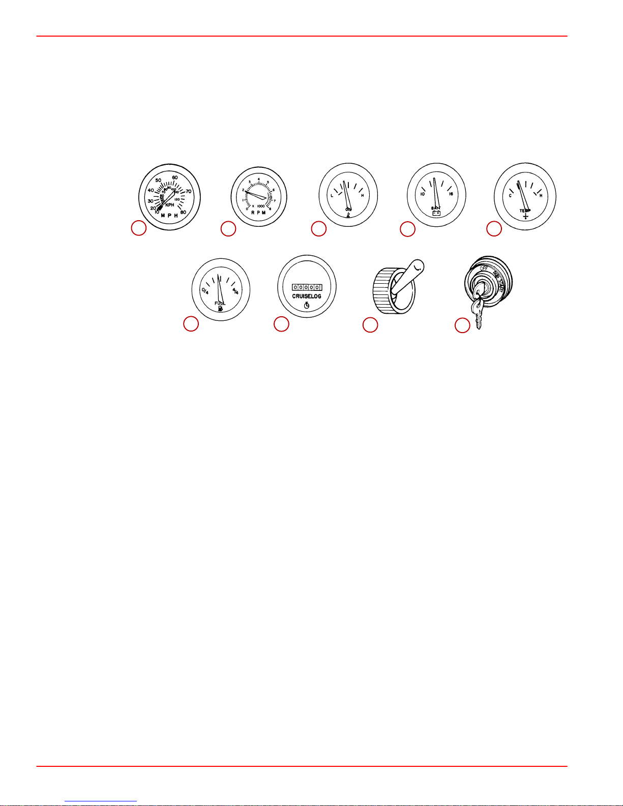
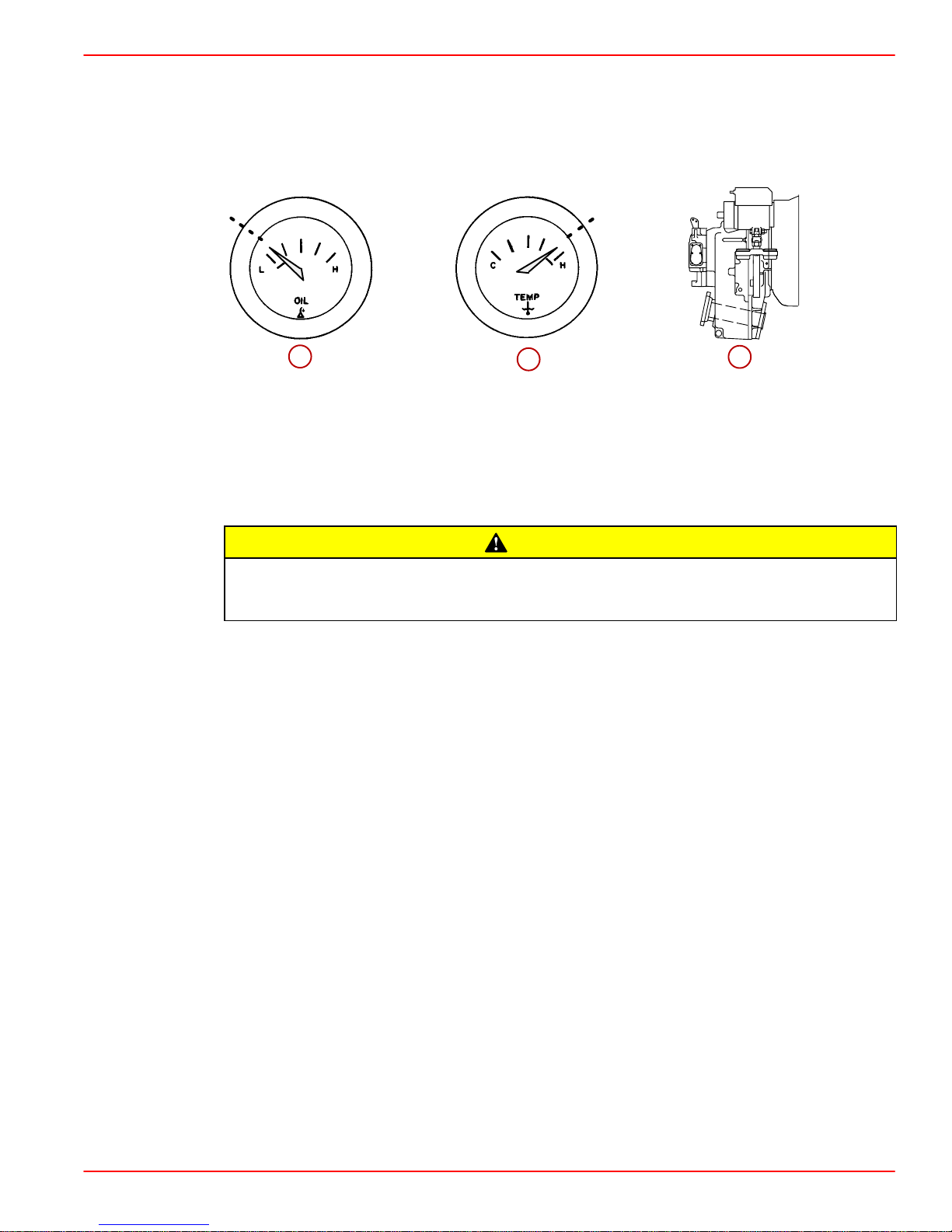
Instrumentation
The following is a brief explanation of the instrumentation typically found on some boats.
The owner/operator should be familiar with all instruments and their functions. Because of
the large variety of instrumentation and manufacturers, you should have your boat dealer
explain the particular gauges and normal readings for your boat.
1
1. Speedometer: Indicates boat speed.
2. Tachometer: Indicates engine rpm.
3. Oil Pressure Gauge: Indicates engine oil pressure.
4. Battery Meter: Indicates battery voltage.
5. Water Temperature Gauge: Indicates engine operating temperature.
6. Fuel Gauge: Indicates quantity of fuel in tank.
7. Hour Meter: Records engine running time.
8. Bilge Blower Switch: Operates bilge blower.
9. Ignition Switch: Allows operator to start and stop engine.
0013
SMARTCRAFT PRODUCT
70514
6
2
70515 70516
70519
7
3
70521
8
4
70522
70517
9
5
70523
70518
A Mercury SmartCraft System instrument package can be purchased for this product. A few
of the functions the instrument package will display are engine rpm, coolant temperature,
water pressure, battery voltage, fuel consumption and engine operating hours.
The SmartCraft Instrument package will also aid in Engine Guardian diagnostics. The
SmartCraft Instrument package will display critical engine alarm data and potential
problems.
Refer to the Mercury SmartCraft Operator ’s Supplement (90-10229021) for the warning
functions monitored and basic operation of the SmartCraft Instrument package.
Page 14 90-864197020 MARCH 2002
Page 21
0014
Remote Controls
Your boat may be equipped with a Mercury Precision Parts or Quicksilver remote controls.
All controls may not have all features shown. Consult your dealer for a description and/or
demonstration of your remote control.
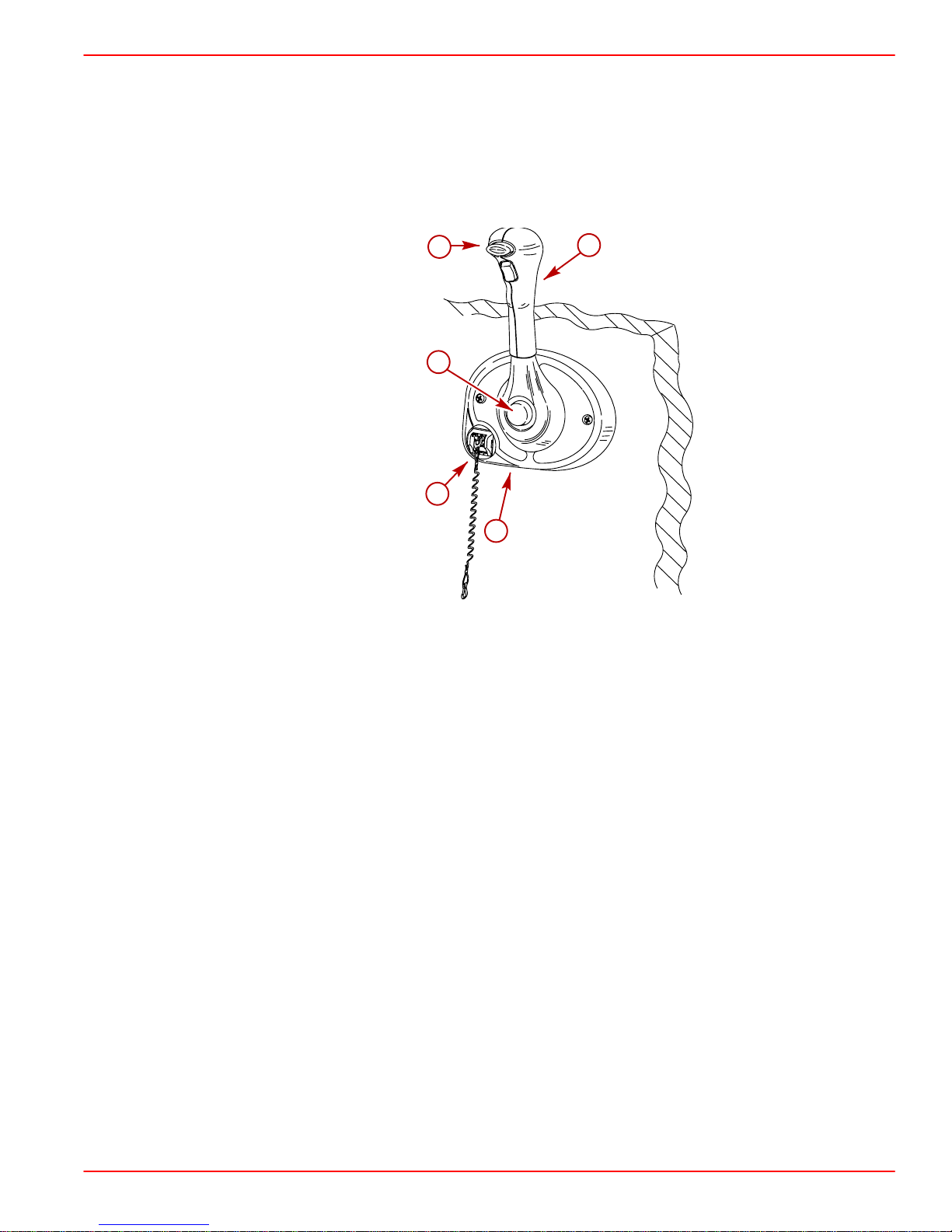
0015
PANEL MOUNTED
GETTING TO KNOW YOUR POWER PACKAGE
1
5
2
3
4
77019
1. Neutral Lock Button - Prevents accidental shift and throttle engagement. Neutral lock
button must be pushed IN to move the control handle out of NEUTRAL.
2. Throttle Only Button - Allows engine throttle advancement without shifting the engine.
This is done by disengaging the shift mechanism from the control handle. The throttle
only button can be depressed only when the remote control handle is in the NEUTRAL
position, and should only be used to assist in starting the engine.
3. Lanyard Stop Switch - Turns the ignition OFF whenever the operator (when attached
to the lanyard) moves far enough away from the operator’s position to activate the
switch. Refer to Lanyard Stop Switch for information on the use of this switch.
4. Control Handle Throttle Friction Screw - This screw (located behind the bezel cover)
can be adjusted to increas or decrease the tension on the control handle. This will help
prevent slipping of the remote control handle. Turn screw clockwise to increase tension
and counterclockwise to decrease tension. Adjust to tension desired.
5. Control Handle - Operation of the shift and throttle are controlled by the movement of
the control handle. Push the control handle forward from NEUTRAL with a quick firm
motion to the first detent for FORWARD gear. Continue pushing forward to increase
speed. Pull the control handle back from NEUTRAL with a quick firm motion to the first
detent for REVERSE gear and continue pushing back to increase speed.
90-864197020 MARCH 2002 Page 15
Page 22
GETTING TO KNOW YOUR POWER PACKAGE
0016
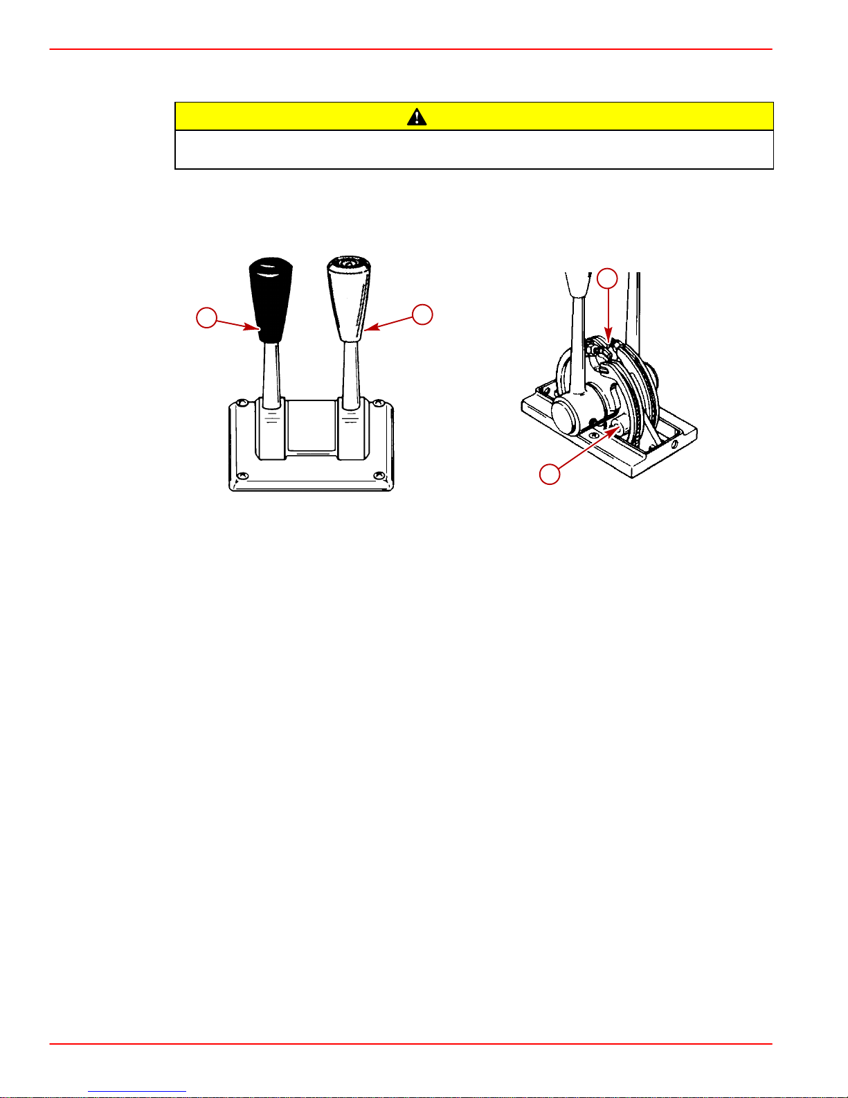
CONSOLE MOUNTED
Avoid possible boat and power package damage. Never shift unit into or out of gear
unless throttle lever is at idle rpm.
IMPORTANT: Boats equipped with dual power packages may have both shift levers
on one control and both throttle levers on the other control.
CAUTION
4
1
2
71339
3
70537
1. Shift Lever - shifts unit into gear with full lever movement. Move lever forward to shift
to FORWARD gear . Move lever backward to shift to REVERSE gear. Lever in full vertical
position shifts to NEUTRAL.
2. Throttle Lever - allows engine rpm to be increased or decreased.
3. FRICTION Screw - adjusts control handle friction so motor speed can be set and driver
does not have to hold handle. Turn screw clockwise to increase friction. Do not thread
screw all the way out.
4. DETENT Screw - controls the effort needed to move control handle out of NEUTRAL.
To increase tension, turn screw clockwise; to decrease, turn screw counterclockwise.
Do not thread screw all the way out.
Page 16 90-864197020 MARCH 2002
Page 23
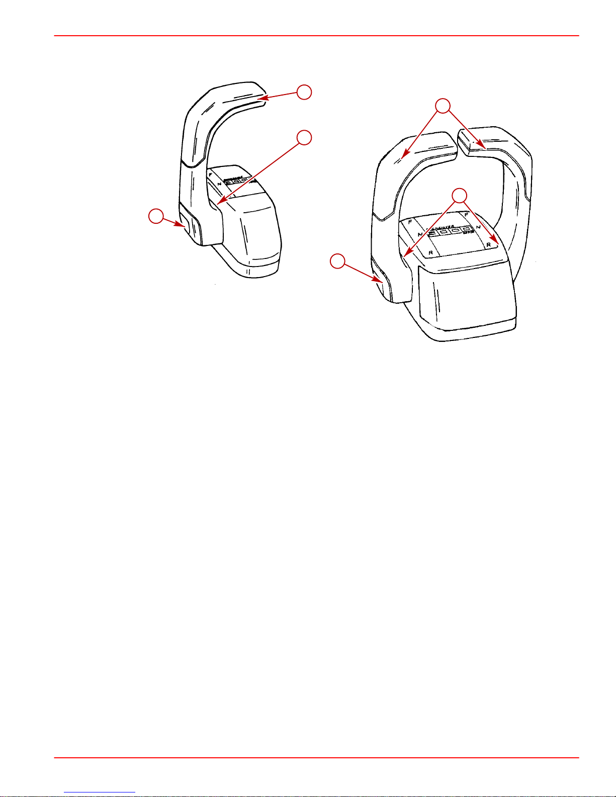
0017
CONSOLE MOUNTED
1
GETTING TO KNOW YOUR POWER PACKAGE
3
3
2
2
1
77971
1. Throttle Only Button - Allows engine throttle advancement without shifting the engine.
This is done by disengaging the shift mechanism from the control handle. The throttle
only button can be depressed only when the remote control handle is in the NEUTRAL
position, and should only be used to assist in starting the engine.
2. Control Handle Tension Adjustment Screw - This screw can be adjusted to increase
or decrease the tension on the control handle (cover must be removed to adjust). This
will help prevent slipping of the remote control handle. Turn screw clockwise to increase
tension and counterclockwise to decrease tension. Adjust to tension desired.
3. Control Handles - Operation of the the shift and throttle are controlled by the movement
of the control handle. Push the control handle forward from NEUTRAL with a quick firm
motion to the first detent for FORWARD gear and continue pushing forward to increase
speed. Pull the control handle back from NEUTRAL with a quick firm motion to the first
detent for REVERSE gear and continue pushing back to increase speed.
90-864197020 MARCH 2002 Page 17
Page 24
GETTING TO KNOW YOUR POWER PACKAGE
0018
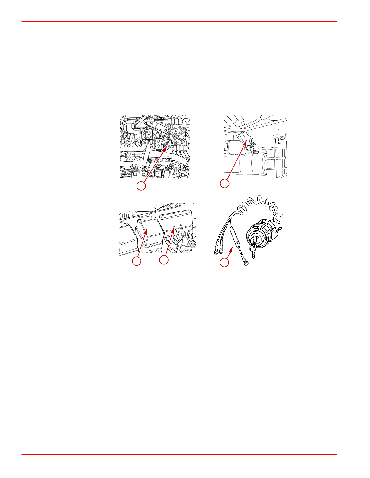
Electrical System Overload Protection
If an electrical overload occurs, a fuse will blow or the circuit breaker will trip open. The cause
must be found and corrected before replacing the fuse or resetting the circuit breaker.
NOTE: In an emergency, when the engine must be operated and the cause for the high
current draw cannot be located and corrected, turn OFF or disconnect all accessories
connected to the engine and instrumentation wiring. Reset the circuit breaker . If the breaker
remains open, the electrical overload has not been eliminated. Further checks must be
made on the electrical system. Contact your authorized Mercury MerCruiser dealer.
0019
1
4
77906
3
77602
2
5
74907
70525
1. A red circuit breaker provides protection for engine wiring harness and the instrumentation power lead. Reset by pushing the “RESET” button IN.
2. A 90 amp fuse is located on the large post of the starter solenoid. This fuse is designed
to protect the engine wiring harness if an electrical overload occurs.
3. Three fuses are located on the port side of the engine. These fuses control various EFI
circuits.
4. The main power and fuel pump relays are located next to the fuses and control voltage
to the engine with the ignition key in the ON position.
5. A 20 amp fuse may be located in the ignition switch I terminal lead to protect the electrical
system. Check for blown fuse if the ignition key is turned to the START position and nothing happens (and circuit breaker is not tripped).
Page 18 90-864197020 MARCH 2002
Page 25
0020
Audio Warning System
Your Mercury MerCruiser power package may be equipped with an Audio Warning System.
The Audio Warning System will not protect the engine from damage. It is designed to warn
the operator that a problem has occurred.
GETTING TO KNOW YOUR POWER PACKAGE
70516
1
The audio warning system will sound with a continuous horn if one of the following occurs:
1. Engine Oil Pressure Too Low
2. Engine Temperature Too Hot
The audio warning system will sound with an intermittent horn if the following occurs:
3. Transmission Fluid Temperature Too Hot
Operation of the engine after the audio warning system alarm has sounded could
result in damage to the power package. Do not operate engine once the alarm has
sounded EXCEPT TO AVOID A HAZARDOUS SITUATION.
If the alarm sounds, stop the engine immediately. Investigate cause and correct it, if
possible. If cause cannot be determined, consult your authorized Mercury MerCruiser
dealer.
0128
TESTING THE AUDIO WARNING SYSTEM
1. Turn the ignition switch to the ON position without cranking the engine.
2. Listen for the alarm to sound indicating that the system is functioning correctly.
70518
2
CAUTION
75542
3
90-864197020 MARCH 2002 Page 19
Page 26

GETTING TO KNOW YOUR POWER PACKAGE
0021
Engine Guardian Strategy
IMPORTANT: Boat speed could be reduced to idle and may not respond to the
throttle.
Engine Guardian Strategy is designed to help reduce the potential for engine damage by
reducing engine power when a potential problem is sensed by the ECM. Engine Guardian
monitors:
• Oil Pressure
• Coolant Temperature
• Seawater Pressure
• Engine Overspeed
Also the Engine Guardian Strategy will reduce engine power to 90 percent of maximum if
any sensor on the power package fails.
For example, if the water inlet becomes partially blocked, Engine Guardian Strategy will
reduce the available power level of the engine to help prevent damage from decreased
water flow to the engine. If the debris passes through and full water flow is restored, engine
power levels are restored to normal.
To avoid a possible recurrence of the problem you should contact an authorized Mercury
MerCruiser dealer. The ECM stores the fault and with this information the technician will be
able to more rapidly diagnose problems.
Page 20 90-864197020 MARCH 2002
Page 27

GETTING TO KNOW YOUR POWER PACKAGE
THIS PAGE IS INTENTIONALLY BLANK
90-864197020 MARCH 2002 Page 21
Page 28

GETTING TO KNOW YOUR POWER PACKAGE
THIS PAGE IS INTENTIONALLY BLANK
Page 22 90-864197020 MARCH 2002
Page 29

Table of Contents
ON THE WATER
ON THE WATER
Safe Boating Suggestions 24. . . . . . . . . . . .
Be Alert To Carbon Monoxide
Poisoning 26. . . . . . . . . . . . . . . . . . . . . . . .
Basic Boat Operation 28. . . . . . . . . . . . . . . .
Launching And Boat Operation Care 28
Starting And Stopping The Engine 29. .
Freezing Temperature Operation 29. . .
Drain Plug and Bilge Pump 29. . . . . . . .
Protecting People In The Water 30. . . . . . .
While You Are Cruising 30. . . . . . . . . . . .
While Boat Is Stationary 30. . . . . . . . . . .
High-Speed And High-Performance
Boat Operation 30. . . . . . . . . . . . . . . . . . . . . .
Wave And Wake Jumping 31. . . . . . . . . . . .
Impact With Underwater Hazards 32. . . . .
Conditions Affecting Operation 33. . . . . . . .
Weight Distribution (Passengers
And Gear) Inside The Boat 33. . . . . . . .
Bottom Of Boat 33. . . . . . . . . . . . . . . . . . .
Cavitation 33. . . . . . . . . . . . . . . . . . . . . . .
Elevation And Climate 34. . . . . . . . . . . . .
Propeller Selection 34. . . . . . . . . . . . . . . .
Getting Started 35. . . . . . . . . . . . . . . . . . . . . .
20-Hour Break-In Period 35. . . . . . . . . . .
After Break-In Period 35. . . . . . . . . . . . . .
End of First Season Checkup 35. . . . . .
3
90-864197020 MARCH 2002 Page 23
Page 30

ON THE WATER
0022
Safe Boating Suggestions
In order to safely enjoy the waterways, familiarize yourself with local and all other
governmental boating regulations and restrictions and also consider the following
suggestions.
• Know and obey all nautical rules and laws of the waterways.
Mercury MerCruiser strongly recommends that all powerboat operators complete a boating
safety course. Courses are offered in the U.S.A. by: The U.S. Coast Guard Auxiliary, The
Power Squadron, The Red Cross and your state or provincial boating law enforcement
agency. Inquiries may be made to the Boating Hotline at 1-800-368-5647 or the Boat U.S.
Foundation at 1-800-336-BOAT.
Y ou should also review the NMMA Sources of W aterway Information booklet. It lists regional
sources of safety, cruising and local navigation and is available at no charge by writing to:
Sources of Waterway Information
National Marine Manufacturers Association
410 N. Michigan Avenue
Chicago, IL 60611 U.S.A.
• Perform safety checks and required maintenance. Follow a regular schedule and
ensure that all repairs are properly made.
• Check safety equipment on board. Here are some suggestions of the types of
safety equipment to carry when boating:
Approved fire extinguishers Paddle or oar
Signal devices: flashlight, rockets or
flares, flag and whistle or horn
Spare propeller, thrust hubs and an
appropriate wrench
Tools necessary for minor repairs First aid kit and instructions
Anchor and extra anchor line Water-proof storage containers
Manual bilge pump and extra drain
plugs
Spare operating equipment, batteries,
bulbs and fuses
Drinking water Compass and map or chart of the area
Transistor radio
Page 24 90-864197020 MARCH 2002
Page 31

ON THE WATER
• Watch for signs of weather change and avoid foul weather and rough-sea
boating.
• Tell someone where you are going and when you expect to return.
• Passenger boarding. Stop the engine whenever passengers are boarding,
unloading or are near the back (stern) of the boat. Shifting the drive unit into neutral
is not sufficient.
• Use personal flotation devices. Federal Law requires that there be a U. S. Coast
Guard approved, wearable-type life jacket (personal flotation device), correctly sized
and readily accessible for every person on board, plus a throwable cushion or ring.
We strongly advise that everyone wear a life jacket at all times while in the boat.
• Prepare other boat operators. Instruct at least one person on board in the basics of
starting and operating the engine and boat handling in case the driver becomes
disabled or falls overboard.
• Do not overload your boat. Most boats are rated and certified for maximum load
(weight) capacities (refer to your boat capacity plate). Know your boat’s operating
and loading limitations. Know if your boat will float if full of water. When in doubt,
contact your authorized Mercury MerCruiser dealer or the boat manufacturer.
• Ensure that everyone in the boat is properly seated. Do not allow anyone to sit or
ride on any part of the boat that was not intended for such use. This includes the
backs of seats, gunwales, transom, bow, decks, raised fishing seats and any rotating
fishing seat; anywhere that sudden unexpected acceleration, sudden stopping,
unexpected loss of boat control or sudden boat movement could cause a person to
be thrown overboard or into the boat. Ensure that all passengers have a proper seat
and are in it before any boat movement.
• Never be under the influence of alcohol or drugs while boating (it is the law).
They impair your judgment and greatly reduce your ability to react quickly.
90-864197020 MARCH 2002 Page 25
Page 32

ON THE WATER
• Know your boating area and avoid hazardous locations.
• Be alert. The operator of the boat is responsible by law to “maintain a proper lookout
by sight and hearing.” The operator must have an unobstructed view particularly to
the front. No passengers, load or fishing seats should block the operators view when
operating the boat above idle or planing transition speed. Watch out for others, the
water and your wake.
• Never drive your boat directly behind a water skier in case the skier falls. As an
example, your boat traveling at 25 MPH (40 km/h) will overtake a fallen skier who
was 61 m (200 ft) in front of you in 5 seconds.
• Watch fallen skiers. When using your boat for water skiing or similar activities,
always keep a fallen or down skier on the operator’s side of the boat while returning
to attend to the skier. The operator should always have the down skier in sight and
never back up to the skier or anyone in the water.
• Report accidents. Boat operators are required by law to file a Boating Accident
Report with their state boating law enforcement agency when their boat is involved in
certain boating accidents. A boating accident must be reported if (1) there is loss of
life or probable loss of life, (2) there is personal injury requiring medical treatment
beyond first aid, (3) there is damage to boats or other property where the damage
value exceeds $500.00 or (4) there is complete loss of the boat. Seek further
assistance from local law enforcement.
0023
Be Alert To Carbon Monoxide Poisoning
Carbon monoxide is present in the exhaust fumes of all internal combustion engines
including the outboards, sterndrives and inboard engines that propel boats, as well as the
generators that power various boat accessories. Carbon monoxide is a deadly gas that is
odorless, colorless and tasteless.
Early symptoms of carbon monoxide poisoning, which should not be confused with
seasickness or intoxication, include headache, dizziness, drowsiness and nausea.
WARNING
Avoid prolonged exposure to carbon monoxide. Carbon monoxide poisoning can
lead to unconsciousness, brain damage or death. Ensure that the boat, while at rest
or underway, is well ventilated.
Page 26 90-864197020 MARCH 2002
Page 33

0024
GOOD VENTILATION
Ventilate the passenger area, open the side curtains or forward hatches to remove fumes.
1. Example of desired air flow through the boat.
0025
POOR VENTILATION
Under certain conditions, permanently enclosed or canvas enclosed cabins or cockpits with
insufficient ventilation may draw in carbon monoxide. Install one or more carbon monoxide
detectors in your boat.
Although the occurrence is rare, on a very calm day, swimmers and passengers in an open
area of a stationary boat that contains or is near an operating engine may be exposed to
a hazardous level of carbon monoxide.
2. Examples of poor ventilation while a boat is stationary:
ON THE WATER
Courtesy of ABYC
a
b
a-Operating the engine when the boat is moored in a confined space.
b-Mooring close to another boat with its engine operating.
3. Examples of poor ventilation while a boat is moving:
a
b
a-Operating the boat with the trim angle of the bow too high.
b-Operating the boat with no forward hatches open (station wagon effect).
Courtesy of ABYC
Courtesy of ABYC
90-864197020 MARCH 2002 Page 27
Page 34

ON THE WATER
0026
Basic Boat Operation
0027
Launching And Boat Operation Care
To avoid possible ingestion of water that can damage engine components:
• Do NOT turn the ignition key off when the engine is above idle speed.
w When launching your boat from a steep ramp, enter the water slowly.
• Do NOT use the lanyard stop switch to shut off the engine above idle speed.
• When coming off plane, if a large following wave may roll over the boat’s
transom, apply a short, light burst of throttle to minimize the wave action against
the stern of the boat.
• Do NOT come off plane quickly, shift into reverse and shut off engine.
0028
OPERATION CHART
CAUTION
BEFORE
STARTING
Open engine hatch.
Turn battery switch
to ON. position
Operate bilge
blowers.
Open fuel shutoff
valve.
Open seacock.
Close the drain
system.
Perform all other
checks specified by
your dealer and/or
boat builder.
Listen for Audio
Warning Alarm to
sound when the
ignition switch is in
the ON position.
Operation Chart
AFTER STARTING
Observe all gauges
to check condition
of engine. If not
normal, stop engine.
Check for fuel, oil,
water, fluid and
exhaust leaks.
Check shift and
throttle control
operation.
Check steering
operation.
WHILE
UNDERWAY
Observe all gauges
to check condition
of engine. If not
normal, stop engine.
Listen for the audio
alarm.
AFTER STOPPING
Turn ignition key to
OFF position.
Turn battery switch
to OFF position.
Close fuel shut off
valve.
Close seacock.
Flush cooling
system if in
saltwater.
Drain bilge.
Page 28 90-864197020 MARCH 2002
Page 35

0029
Starting And Stopping The Engine
NOTE: Only perform those functions applicable to your power package.
1. Check all items listed in Operation Cart.
2. Place the remote control handle in NEUTRAL.
Overheating from insufficient cooling water will cause engine and drive system
damage. Ensure that there is sufficient water always available at water inlet holes
during operation.
Explosive gasoline fumes collect in the engine compartment. Avoid injury or
property damage, operate the bilge blower for at least five minutes prior to starting
the engine. If the boat is not equipped with a bilge blower, open the engine hatch
and leave it open while starting the engine.
3. Position throttle setting as follows:
a. COLD AND WARM ENGINE - Leave in the NEUTRAL/IDLE speed position.
ON THE WATER
CAUTION
WARNING
b. FLOODED ENGINE - Turn ignition switch to the ON position. Push the THROTTLE
ONLY button and place the throttle lever at 50% position. Attempt to start engine.
As soon as engine starts, return the throttle to the IDLE position.
IMPORTANT: Do not operate starter motor continuously for more than 30 seconds.
4. Turn ignition key to START . Release key when engine starts and allow switch to return
to ON position.
5. If engine is cold, operate engine for 1 or 2 minutes at fast IDLE (1000-1500 rpm) or until
engine temperature reaches 140-160 degrees F (60-71 degrees C).
6. Inspect the power package for fuel, oil, water and exhaust leaks.
7. To shift into gear, move control handle with a firm, quick motion forward to shift to FOR-
WARD gear, or backward to shift to REVERSE. After shifting drive unit, advance throttle
to desired setting.
8. Move the remote control handle to NEUTRAL/IDLE and allow the engine to slow to IDLE
speed. If engine has been operated at high speed for a long period of time, allow the
engine to cool at IDLE speed for 3 to 5 minutes.
9. Turn ignition key to the OFF position.
0030
Freezing Temperature Operation
IMPORTANT: If the boat is operated during periods of freezing temperature,
precautions must be taken to prevent freeze damage to the power package. Damage
caused by freezing IS NOT covered by Mercury MerCruiser Limited Warranty.
0031
Drain Plug and Bilge Pump
The engine compartment in your boat is a natural place for water to collect. For this reason,
boats are normally equipped with a drain plug and/or a bilge pump. It is very important to
check these items on a regular basis to ensure that the water level does not come into
contact with your power package. Components on your engine will be damaged if
submerged. Damage caused by submersion is not covered by the Mercury MerCruiser
Limited Warranty.
90-864197020 MARCH 2002 Page 29
Page 36

ON THE WATER
0032
Protecting People In The Water
While You Are Cruising
It is very difficult for a person standing or floating in the water to take quick action to avoid
a boat heading in his/her direction even at slow speed.
Always slow down and exercise extreme caution any time you are boating in an area where
there might be people in the water.
Whenever a boat is moving (coasting) in NEUTRAL/IDLE, there is sufficient force by the
water on the propeller to cause the propeller to rotate. This neutral propeller rotation can
cause serious injury.
While Boat Is Stationary
Stop your engine immediately whenever anyone in the water is near your boat.
Serious injury to the person in the water is likely if contacted by a rotating propeller ,
a moving boat, a gear case or any solid device rigidly attached to a moving boat or
gear case.
WARNING
Shift into the NEUTRAL/IDLE position and shut off the engine before allowing people to
swim or be in the water near your boat.
0033
High-Speed And High-Performance Boat Operation
If your boat is considered a high-speed or high-performance boat with which you are
unfamiliar, we recommend that you never operate it at its high speed capability without first
requesting an initial orientation and demonstration ride with your dealer or an operator
experienced with your boat. For additional information, refer to Hi-Performance Boat
Operation booklet (90-849250--1) from your dealer, distributor or Mercury Marine.
Page 30 90-864197020 MARCH 2002
Page 37

0034
Wave And Wake Jumping
Avoid serious injury or death from being thrown within or out of a boat when it lands
after jumping a wave or wake. Avoid wave or wake jumping whenever possible.
Instruct all occupants that if a wake or wave jump occurs, get low and hang on to
a boat hand hold.
Operating recreational boats over waves and wakes is a natural part of boating. However,
when this activity is done with enough speed to force the boat hull partially or completely
out of the water, certain hazards arise, particularly when the boat re-enters the water.
The primary concern is the boat changing direction while in the midst of the jump. In such
cases the landing may cause the boat to violently veer in a new direction. Such a sharp
change in direction or turn can cause occupants to be thrown out of their seats or out of the
boat.
ON THE WATER
WARNING
There is another less common hazardous result from allowing your boat to launch off of a
wave or wake. If the bow of your boat pitches down far enough while airborne, upon water
contact it may penetrate under the water surface and submarine for an instant. This will bring
the boat nearly to a stop in an instant and can send the occupants flying forward. The boat
may also veer sharply to one side.
90-864197020 MARCH 2002 Page 31
Page 38

ON THE WATER
0035
Impact With Underwater Hazards
Reduce speed and proceed with caution whenever you’re driving a boat in shallow water
or in areas where the waters are suspected of having underwater obstacles that could be
struck by the underwater drive components, rudder or the boat bottom.
IMPORTANT: The most important thing you can do to help reduce injury or impact
damage from striking a floating or underwater object is control the boat speed. Under
these conditions, boat speed should be kept to a maximum speed of 24 to 40 km/h
(15 to 25 MPH).
Striking a floating/underwater object may result in an infinite number of situations. Some of
these situations could result in the following:
• The boat could move suddenly in a new direction. Such a sharp change in direction
or turn can cause occupants to be thrown out of their seats or out of the boat.
• A rapid reduction in speed. This will cause occupants to be thrown forward, even out
of the boat.
• Impact damage to the underwater drive components, rudder and/or boat.
Keep in mind, one of the most important things you can do to help reduce injury or impact
damage in these situations is control the boat speed. Boat speed should be kept to a
minimum planing speed when driving in waters known to have underwater obstacles.
After striking a submerged object, stop the engine as soon as possible and inspect the drive
system for any broken or loose parts. If damage is present or suspected, the power package
should be taken to an authorized Mercury MerCruiser dealer for a thorough inspection and
necessary repair.
The boat should be checked for hull fractures, transom fractures and water leaks.
Operating with damaged underwater drive components, rudder or boat bottom could cause
additional damage to other parts of the power package, or could affect control of the boat.
If continued operation is necessary, do so at greatly reduced speeds.
WARNING
Avoid serious injury or death from loss of boat control. Continued boating with
major impact damage can result in sudden component failure with or without
subsequent impacts. Have the power package thoroughly inspected and any
necessary repairs made.
Page 32 90-864197020 MARCH 2002
Page 39

0036
Conditions Affecting Operation
Weight Distribution (Passengers And Gear) Inside The Boat
Shifting weight to rear (stern):
• Generally increases speed and engine rpm
• Causes bow to bounce in choppy water
• Increases danger of following wave splashing into the boat when coming off plane
• At extremes, can cause the boat to porpoise
Shifting weight to front (bow):
• Improves ease of planing
• Improves rough water ride
• At extremes, can cause the boat to veer back and forth (bow steer)
0037
Bottom Of Boat
ON THE WATER
0038
Cavitation
To maintain maximum speed, the boat bottom should be:
• Clean, free of barnacles and marine growth
• Free of distortion; nearly flat where it contacts the water
• Straight and smooth, fore and aft
Marine vegetation may accumulate when the boat is docked. This growth must be removed
before operation; it may clog the water inlets and cause the engine to overheat.
Cavitation occurs when water flow cannot follow the contour of a fast-moving underwater
object, such as a gear housing or a propeller. Cavitation permits the propeller to speed up,
but the boat speed to reduce. Cavitation can seriously erode the surface of the gear housing
or the propeller. Common causes of cavitation are:
• Weeds or other debris snagged on the propeller
• Bent propeller blade
• Raised burrs or sharp edges on the propeller
90-864197020 MARCH 2002 Page 33
Page 40

ON THE WATER
0039
Elevation And Climate
Elevation and climate changes will affect the performance of your power package. Loss of
performance can be caused by:
• Higher elevations
• Higher temperatures
• Low barometric pressures
• High humidity
For you to have optimum engine performance under changing weather conditions, it is
essential that the engine be propped to allow the engine to operate at or near the top end
of the specified maximum rpm range with a normal boat load during your normal boating
weather conditions.
In most cases, performance can be regained by changing to a lower pitch propeller.
0040
Propeller Selection
IMPORTANT: The engines covered in this manual are equipped with an rpm
rev-limiter that is set to an upper (or limited) rpm amount. This limit is slightly above
the normal operating range of the engine and is designed to help prevent damage
from excessive engine rpm. Once the rpm drop into the recommended operating rpm
range normal engine operation resumes.
It is the responsibility of the boat manufacturer and/or the selling dealer to equip the power
package with the correct propeller. Refer to Everything You Need To Know About
Propellers (90-8614492).
Select a propeller that will allow the engine power package to operate at or near the top end
of the recommended WOT operating rpm range with a normal load.
If full throttle operation is below the recommended range, the propeller must be changed
to prevent loss of performance and possible engine damage. On the other hand, operating
an engine above the recommended operating rpm range will cause higher than normal wear
and/or damage.
After initial propeller selection, the following common problems may require that the
propeller be changed to a lower pitch.
• Warmer weather and greater humidity cause a loss of rpm.
• Operating in a higher elevation causes a loss of rpm.
• Operating with a dirty boat bottom causes a loss of rpm.
• Operating with increased load (additional passengers, pulling skiers) causes a loss
of rpm.
For better acceleration, such as is needed for water skiing, use the next lower pitch
propeller. Do not operate at full throttle when using the lower pitch propeller, but not pulling
skiers.
Page 34 90-864197020 MARCH 2002
Page 41

0042
Getting Started
0041
20-Hour Break-In Period
IMPORTANT: The first 20 hours of operation is the engine break-in period. Correct
break-in is essential to obtain minimum oil consumption and maximum engine
performance. During this break-in period, the following rules must be observed:
• Do NOToperate below 1500 rpm for extended periods of time for the first 10 hours.
Shift into gear as soon as possible after starting and advance the throttle above 1500
rpm if conditions permit safe operation.
• Do NOT operate at one speed consistently for extended periods.
• Do NOT exceed 3/4 throttle during the first 10 hours. During the next 10 hours,
occasional operation at full throttle is permissible (5 minutes at a time maximum).
• Avoid full throttle acceleration from IDLE speed.
• Do NOT operate at full throttle until the engine reaches normal operating
temperature.
ON THE WATER
• Frequently check engine oil level. Add oil as needed. It is normal for oil consumption
to be high during the break-in period.
0043
After Break-In Period
To help extend the life of your Mercury MerCruiser power package, the following
recommendations should be considered;
• Ensure that propeller allows the engine to operate at or near the top of the specified
WOT rpm range (Refer to Specifications And Maintenance) when at full throttle with
a normal boat load.
• Operation at 3/4 throttle setting or lower is recommended. Refrain from prolonged
operation at WOT rpm.
• Change the oil and oil filter. Refer to Specifications And Maintenance.
0044
End of First Season Checkup
At the end of the first season of operation, contact an authorized Mercury MerCruiser dealer
to discuss and/or perform scheduled maintenance items. If you are in an area where the
product is operated continuously year-round you should contact your dealer at the end of
the first 100 hours of operation or once yearly, whichever occurs first.
90-864197020 MARCH 2002 Page 35
Page 42

ON THE WATER
THIS PAGE IS INTENTIONALLY BLANK
Page 36 90-864197020 MARCH 2002
Page 43

SPECIFICATIONS AND MAINTENANCE
Table of Contents
SPECIFICATIONS AND MAINTENANCE
Specifications 38. . . . . . . . . . . . . . . . . . . . . . .
Fuel Recommendations 38. . . . . . . . . . .
Engine Oil 40. . . . . . . . . . . . . . . . . . . . . . .
Engine Specifications 41. . . . . . . . . . . . .
Fluid Specifications 42. . . . . . . . . . . . . . .
Owner/Operator Responsibilities 43. . . . . .
Dealer Responsibilities 43. . . . . . . . . . . . . . .
Maintenance 44. . . . . . . . . . . . . . . . . . . . . . . .
Do-It-Yourself Maintenance
Suggestions 45. . . . . . . . . . . . . . . . . . . . .
Inspection 46. . . . . . . . . . . . . . . . . . . . . . .
Inboard Maintenance Chart 46. . . . . . . .
Maintenance Record 49. . . . . . . . . . . . . .
Engine Oil 50. . . . . . . . . . . . . . . . . . . . . . . . . .
Checking 50. . . . . . . . . . . . . . . . . . . . . . . .
Filling 51. . . . . . . . . . . . . . . . . . . . . . . . . . .
Changing Oil and Filter 52. . . . . . . . . . . .
Transmission Fluid 54. . . . . . . . . . . . . . . .
Lubrication 55. . . . . . . . . . . . . . . . . . . . . . . . .
Throttle Cable 55. . . . . . . . . . . . . . . . . . . .
Transmission Linkage 55. . . . . . . . . . . .
Engine Coolant - Closed Cooled
Models Only 56. . . . . . . . . . . . . . . . . . . . . . . .
Checking 56. . . . . . . . . . . . . . . . . . . . . . . .
Filling 57. . . . . . . . . . . . . . . . . . . . . . . . . . .
Changing 57. . . . . . . . . . . . . . . . . . . . . . . .
Flame Arrestor and
Related Components 58. . . . . . . . . . . . . . . .
Cleaning 58. . . . . . . . . . . . . . . . . . . . . . . .
Positive Crankcase
Ventilation Valve (PCV) 59. . . . . . . . . . . .
Water Separating Fuel Filter 60. . . . . . . . . .
Changing 60. . . . . . . . . . . . . . . . . . . . . . . .
In-line Fuel Filter 62. . . . . . . . . . . . . . . . . . . .
Changing 62. . . . . . . . . . . . . . . . . . . . . . . .
Battery 64. . . . . . . . . . . . . . . . . . . . . . . . . . . . .
Multiple EFI Engine
Battery Precautions 64. . . . . . . . . . . . . . .
Serpentine Drive Belt 65. . . . . . . . . . . . . . . .
Cold Weather Or Extended Storage 68. . .
Preparing Your Power
Package For Storage 68. . . . . . . . . . . . .
Draining Instructions 70. . . . . . . . . . . . . . . . .
Identification 71. . . . . . . . . . . . . . . . . . . . .
Boat In Water 72. . . . . . . . . . . . . . . . . . . .
Boat Out Of The Water 76. . . . . . . . . . . .
All Models 78. . . . . . . . . . . . . . . . . . . . . . .
Flushing The Power Package 79. . . . . . . . .
Inboards 79. . . . . . . . . . . . . . . . . . . . . . . . .
Tow Sports 81. . . . . . . . . . . . . . . . . . . . . .
Power Package Recommissioning 83. . . . .
Emissions (Europe Only) 84. . . . . . . . . . . . .
Emissions Testing 84. . . . . . . . . . . . . . . .
Installing Test Probes 84. . . . . . . . . . . . .
4
90-864197020 MARCH 2002 Page 37
Page 44

SPECIFICATIONS AND MAINTENANCE
0045
Specifications
Fuel Recommendations
IMPORTANT: Use of improper gasoline can damage your engine. Engine damage
resulting from the use of improper gasoline is considered misuse of the engine, and
damage caused thereby will not be covered under the limited warranty.
FUEL RATINGS
Mercury MerCruiser engines will operate satisfactorily when using a major brand of
unleaded gasoline meeting the following specifications:
USA and Canada - having a posted pump Octane Rating of 87 (R+M)/2 minimum. Premium
gasoline [92 (R+M)/2 Octane] is also acceptable. DO NOT use leaded gasoline.
Outside USA and Canada - having a posted pump Octane Rating of 90 RON minimum.
Premium gasoline (98 RON) is also acceptable. If unleaded gasoline is not available, use
a major brand of leaded gasoline.
0046
USING REFORMULATED (OXYGENATED) GASOLINES (USA ONLY)
This type of gasoline is required in certain areas of the USA. The two types of oxygenates
used in these fuels is Alcohol (Ethanol) or Ether (MTBE or ETBE). If Ethanol is the oxygenate
that is used in the gasoline in your area, refer to Gasolines Containing Alcohol.
These Reformulated Gasolines are acceptable for use in your Mercury MerCruiser engine.
Page 38 90-864197020 MARCH 2002
Page 45

0047
GASOLINES CONTAINING ALCOHOL
If the gasoline in your area contains either methanol (methyl alcohol) or ethanol (ethyl
alcohol), you should be aware of certain adverse effects that can occur. These adverse
effects are more severe with methanol. Increasing the percentage of alcohol in the fuel can
also worsen these adverse effects.
Some of these adverse effects are caused because the alcohol in the gasoline can absorb
moisture from the air, resulting in a separation of the water/alcohol from the gasoline in the
fuel tank.
The fuel system components on your Mercury MerCruiser engine will withstand up to 10%
alcohol content in the gasoline. We do not know what percentage your boat’s fuel system
will withstand. Contact your boat manufacturer for specific recommendations on the boats
fuel system components (fuel tanks, fuel lines, and fittings). Be aware that gasolines
containing alcohol may cause increased:
• Corrosion of metal parts
• Deterioration of rubber or plastic parts
• Fuel permeation through rubber fuel lines
• Starting and operating difficulties
SPECIFICATIONS AND MAINTENANCE
WARNING
FIRE AND EXPLOSION HAZARD: Fuel leakage from any part of the fuel system can
be a fire and explosion hazard which can cause serious bodily injury or death. Careful periodic inspection of entire fuel system is mandatory, particularly after storage.
All fuel components should be inspected for leakage, softening, hardening, swelling or corrosion. Any sign of leakage or deterioration requires replacement before
further engine operation.
Because of possible adverse effects of alcohol in gasoline, it is recommended that only
alcohol-free gasoline be used where possible. If only fuel containing alcohol is available, or
if the presence of alcohol is unknown, increased inspection frequency for leaks and
abnormalities is required.
IMPORTANT: When operating a Mercury MerCruiser engine on gasoline containing
alcohol, storage of gasoline in the fuel tank for long periods should be avoided. Long
periods of storage, common to boats, create unique problems. In cars alcohol-blend
fuels normally are consumed before they can absorb enough moisture to cause
trouble, but boats often sit idle long enough for phase separation to take place. In
addition, internal corrosion may take place during storage if alcohol has washed
protective oil films from internal components.
90-864197020 MARCH 2002 Page 39
Page 46

SPECIFICATIONS AND MAINTENANCE
0048
Engine Oil
To help obtain optimum engine performance and to provide maximum protection, we
strongly recommend the use of Quicksilver 4-Cycle 25W-40 Marine Engine Oil. This oil is
a special blend of 25-weight and 40-weight oils for marine engines. If not available, a good
grade, straight weight, detergent automotive oil of correct viscosity, with an API
classification of SJ, CF-2, CH-4 may be used.
In those areas where Quicksilver 4-Cycle 25W-40 Marine Engine Oil or a recommended
straight weight oil are not available, a multi-viscosity 20W-40 or, a less preferable choice,
20W-50, with API service ratings of SJ, CF-2, CH-4 may be used.
IMPORTANT: The use of non-detergent oils, multi-viscosity oils (other than
Quicksilver 25W-40 or a good quality 20W-40 or 20W-50), synthetic oils, low quality
oils or oils that contain solid additives are specifically not recommended.
The chart below is a guide to engine oil selection.
Quicksilver 4-Cycle 25W-40 Marine Engine Oil
SAE 40W
SAE 20W
SAE 30W
32° F
0
° C
AIR TEMPERATURE
50
10
° F
° C
75796
Page 40 90-864197020 MARCH 2002
Page 47

0049
Engine Specifications
0050
SPECIFICATIONS AND MAINTENANCE
Models
Propshaft Horsepower
Propshaft Kilowatts
1
350 MAG
MPI Tow
Sports
1
315 300 300 315 320
350
MAG
MPI
235 224 224 234 238
350
MAG
MPI
Horizon
MX 6.2
MPI
MX 6.2
MPI
Horizon
Displacement 350 cid (5.7 liter) 377 cid (6.2 liter)
Specified WOT rpm
Range
Idle rpm in NEUTRAL
2
2
Minimum Oil Pressure @
2000 rpm
4
Minimum Oil Pressure @
4
Idle
4600-5000 4400-4800 4600-5000
3
600
124 kPa (18 psi)
41 kPa (6 psi)
Thermostat 71 degrees C (160 degrees F)
Timing @ Idle
3
0 degrees
Firing Order 1-8-4-3-6-5-7-2
Electrical System 12-Volt Negative (–) Ground
Alternator Rating - Hot
Operating Amps
Alternator Rating - Cold
Operating Amps
Recommended Battery
Rating (Minimum)
550 cca / 825 mca / 150 Ah
65 amp
72 amp
Spark Plug Type AC Platinum (AC 41-932)
Spark Plug Gap 0.060 in.
1 Power Rated in Accordance with NMMA (National Marine Manufacturers’ Association) rating procedures.
2
Measured using an accurate service tachometer, with engine at normal operating temperature.
3
Idle speed on EFI models is not adjustable.
4
Oil pressure must be checked with engine at normal operating temperature.
90-864197020 MARCH 2002 Page 41
Page 48

SPECIFICATIONS AND MAINTENANCE
0051
Fluid Specifications
0052
ENGINE
IMPORT ANT: It may be necessary to adjust oil levels depending on installation angle
and cooling systems (heat exchanger and fluid lines).
0053
TRANSMISSION
All Models
Capacity
Fluid Type
Liters (U.S. qts)
Crankcase Oil (With
Filter)
1
Seawater Cooling
System
2
5.20 (5-1/2)
20 (21) Propylene Glycol and Purified Water
Quicksilver 4-Cycle 25W-40 Marine
Engine Oil
Mercury Extended Life
Closed Cooling
System
19 (20)
Coolant/Antifreeze or Extended Life
Ethylene Glycol 5/100
Antifreeze/Coolant mixed 50/50 with
Purified Water
1
Always use the dipstick to determine the exact quantity of oil or fluid required.
2
Seawater Cooling System capacity information is for winterization use only.
Model
Capacity
Fluid Type
Liters (U.S. qts)
5000A 2.84 (3)
5000V 3.30 (3-1/2)
71C In-Line 1.66 (1-3/4)
71C Gear Reduction 2.84 (3)
71C Remote V-Drive 1.66 (1-3/4)
Dexron III Automatic Transmission
Dexron III Automatic Transmission
Fluid or Equivalent
Mobil 424 or
Dexron III Automatic Transmission
Do Not Mix!
72C In-Line 1.66 (1-3/4)
72C Gear Reduction 1.66 (1-3/4)
72C Remote V-Drive 1.66 (1-3/4)
Universal Tractor Hydraulic Oil
Mobil 424 or
Do Not Mix!
72C V-Drive 3.79 (4)
Fluid
Fluid
630A 4.00 (4-1/2)
630V 4.00 (4-1/2)
Page 42 90-864197020 MARCH 2002
Dexron III Automatic Transmission
Dexron III Automatic Transmission
Fluid
Page 49

0054
Owner/Operator Responsibilities
It is the operator’s responsibility to perform all safety checks, to ensure that all lubrication
and maintenance instructions are complied with for safe operation and to return the unit to
an authorized Mercury MerCruiser dealer for a periodic checkup.
Normal maintenance service and replacement parts are the responsibility of the
owner/operator and as such, are not considered defects in workmanship or material within
the terms of the warranty. Individual operating habits and usage contribute to the need for
maintenance service.
Proper maintenance and care of your power package will ensure optimum performance and
dependability and will keep your overall operating expenses at a minimum. See your
authorized Mercury MerCruiser dealer for service aids.
0055
Dealer Responsibilities
In general, a dealer’s responsibilities to the customer include predelivery inspection and
preparation such as:
SPECIFICATIONS AND MAINTENANCE
• Ensure that the boat is properly equipped.
• Prior to delivery, make certain that the Mercury MerCruiser power package and other
equipment are in proper operating condition.
• Make all necessary adjustments for maximum efficiency.
• Familiarize the customer with the on-board equipment.
• Explain and demonstrate the operation of the power package and boat.
• Provide you with a copy of a Predelivery Inspection Checklist.
• Your selling dealer should fill out the Warranty Registration Card completely and mail
it to the factory immediately upon sale of the new product.
90-864197020 MARCH 2002 Page 43
Page 50

SPECIFICATIONS AND MAINTENANCE
0056
Maintenance
Avoid injury or death and power package damage from an electrical shock, fire or
explosion. Always disconnect both battery cables from the battery before servicing
the power package.
Fuel vapors can be present in the engine compartment. Avoid injury or power
package damage caused by fuel vapors or explosion. Always ventilate the engine
compartment prior to servicing the power package.
IMPORTANT: Refer to MAINTENANCE CHART for complete listing of all scheduled
maintenance to be performed. Some listings can be done by owner/operator, while
others should be performed by an authorized Mercury MerCruiser dealer. Before
attempting maintenance or repair procedures not covered in this manual, it is
recommended that a Mercury MerCruiser Service Manual be purchased and read
thoroughly.
NOTE: Maintenance points are color coded for ease of identification. See the decal on
engine for identification.
WARNING
CAUTION
• Blue-Coolant
• Yellow-Engine Oil
• Orange-Fuel
• Brown-Transmission Fluid
Page 44 90-864197020 MARCH 2002
Page 51

0057
Do-It-Yourself Maintenance Suggestions
Present-day marine equipment, such as your Mercury MerCruiser power package, are
highly technical pieces of machinery. Electronic ignition and special fuel delivery systems
provide greater fuel economies, but also are more complex for the untrained mechanic.
If you are one of those persons who likes to do-it-yourself, here are some suggestions for
you.
• Do not attempt any repairs unless you are aware of the Cautions, Warnings and
procedures required. Your safety is our concern.
• If you attempt to service the product yourself, we suggest you order the service
manual for that model. The service manual outlines the correct procedures to follow.
It is written for the trained mechanic, so there may be procedures you don’t
understand. Do not attempt repairs if you do not understand the procedures.
• There are special tools and equipment that are required to perform some repairs. Do
not attempt these repairs unless you have these special tools and/or equipment. You
can cause damage to the product in excess of the cost a dealer would charge you.
• Also, if you partially disassemble an engine or drive assembly and are unable to
repair it, the dealer’s mechanic must reassemble the components and test to
determine the problem. This will cost you more than taking it to the dealer
immediately upon having a problem. It may be a very simple adjustment to correct
the problem.
SPECIFICATIONS AND MAINTENANCE
• Do not telephone the dealer, service office or the factory to attempt for them to
diagnose a problem or to request the repair procedure. It is difficult for them to
diagnose a problem over the telephone.
Your authorized dealer is there to service your power package. They have qualified
factory-trained mechanics.
It is recommended you have the dealer do periodic maintenance checks on your power
package. Have them winterize it in the fall and service it before the boating season. This will
reduce the possibility of any problems occurring during your boating season when you want
trouble-free boating pleasure.
90-864197020 MARCH 2002 Page 45
Page 52

SPECIFICATIONS AND MAINTENANCE
0058
Inspection
Inspect your power package often, and at regular intervals, to help maintain its top operating
performance and correct potential problems before they occur. The entire power package
should be checked carefully, including all accessible engine parts.
Check for loose, damaged or missing parts, hoses and clamps; tighten or replace as
necessary.
Check plug leads and electrical leads for damage.
Remove and inspect the propeller . If badly nicked, bent or cracked, contact your authorized
Mercury MerCruiser dealer.
Repair nicks and corrosion damage on power package exterior finish. Contact your
authorized Mercury MerCruiser dealer.
0059
Inboard Maintenance Chart
Routine Maintenance *
Check the engine oil (interval can be
Each
Day
Start
Each
Day
End
Weekly
extended based on experience).
If operating in salt, brackish or polluted
waters, flush the cooling system after each
use.
Check the transmission fluid.
Check the water inlets for debris or marine
growth. Check the water strainer and clean.
Check the coolant level.
Check the battery connections and the fluid
level.
Ensure that the gauges and the wiring
connections are secure. Clean the gauges.
* Only perform maintenance which applies to your particular power package
1
If operating in saltwater, interval is reduced to every 25 hours or 30 days whichever occurs first
1
Every
Two
Months
or
50 hours
Page 46 90-864197020 MARCH 2002
Page 53

0060
Inboard Maintenance Chart (continued)
Scheduled Maintenance *
SPECIFICATIONS AND MAINTENANCE
Every
100
Annually
hours or
Annually
Touch-up paint power
package and spray with
corrosion guard.
Change the engine oil
and the filter.
Change the transmission
fluid.
Replace the fuel filters.
Check the steering
system and the remote
control for loose, missing
or damaged parts.
Lubricate the cables and
the linkages.
Retorque the engine
mounts.
Check the spark plugs,
the wires, and the
distributor cap.
Clean the flame arrestor
and the engine
ventilation hoses.
Replace the PCV valve.
Check the electrical
system for loose,
damaged or corroded
fasteners.
Inspect the condition
and the tension of the
belts.
Every
200
hours
or 3
years
Every
300
hours
or 3
years
Every
2
years
Every
5
years
Per
OEM
* Only perform maintenance which applies to your particular power package
Whichever occurs first
90-864197020 MARCH 2002 Page 47
Page 54

SPECIFICATIONS AND MAINTENANCE
Inboard Maintenance Chart (continued)
Scheduled Maintenance *
Check the cooling
system and the exhaust
system hose clamps for
tightness. Inspect both
systems for damage or
leaks.
Disassemble and
inspect the seawater
pump and replace the
worn components.
Clean the seawater
section of the closed
cooling system. Clean,
inspect and test the
pressure cap.
Replace the coolant.
Annually
Every
100
hours or
Annually
Every
200
hours
or 3
years
Every
300
hours
or 3
years
Every
2
years
Every
5
years
Per
OEM
Check the
engine-to-propeller shaft
alignment.
* Only perform maintenance which applies to your particular power package
Whichever occurs first
Interval will be reduced if not using extended life coolant
Page 48 90-864197020 MARCH 2002
Page 55

0166
Maintenance Record
SPECIFICATIONS AND MAINTENANCE
Date
Hour Meter
Reading
Serviced By
Maintenance Per-
formed
90-864197020 MARCH 2002 Page 49
Page 56

SPECIFICATIONS AND MAINTENANCE
0062
Engine Oil
ENVIRONMENTAL HAZARD! Discharge of oil or oil waste into the environment is
restricted by law. Do not spill oil or oil waste into the environment when using or
servicing your boat. Contain and dispose of oil or oil waste as defined by local
authorities.
0063
Checking
1. Stop the engine. Allow approximately five minutes for the oil to drain into the oil pan. The
boat must be at rest in the water.
CAUTION
a
a
aa
a-Dipstick Tubes
2. Remove the dipstick. Wipe clean and reinstall fully into the dipstick tube.
3. Remove the dipstick and observe the oil level. Oil level must be between FULL or OK
RANGE and ADD. Fill as necessary with specified fluid.
All Models
Engine Oil (With
Filter)
1
Always use dipstick to determine exact quantity of oil or fluid required.
1
77808
Capacity
Fluid Type
78027
Liters (U.S. qts)
5.25 (5-1/2) 4-Cycle 25W-40 Marine Engine Oil
Page 50 90-864197020 MARCH 2002
Page 57

0064
Filling
SPECIFICATIONS AND MAINTENANCE
IMPORTANT: Do not overfill the engine with oil.
1. Remove oil fill cap.
77842
2. Add the specified engine oil to bring the level up to, but not over , the FULL or OK RANGE
mark on the dipstick. Refer to Specifications.
All Models
Capacity
Liters (U.S. qts)
Engine Oil (With
Filter)
1
Always use the dipstick to determine the exact quantity of oil or fluid required.
1
5.25 (5-1/2) 4-Cycle 25W-40 Marine Engine Oil
3. Replace the fill cap.
Fluid Type
90-864197020 MARCH 2002 Page 51
Page 58

SPECIFICATIONS AND MAINTENANCE
0065
Changing Oil and Filter
Refer to the Maintenance schedule for the change interval. engine oil should be changed
before placing the boat in storage.
IMPORTANT: Change engine oil when the engine is warm from operation. Warm oil
flows more freely, carrying away more impurities. Use only recommended engine oil
(refer to Specifications).
0066
QUICK DRAIN OIL
1. Remove the bilge drain plug.
2. Pull tether through the bilge drain.
3. Place the oil drain hose in a suitable container.
4. Remove the drain plug from the oil drain hose.
5. After oil has drained completely, install the drain plug in the oil drain hose.
6. Push the hose through bilge drain and install the plug.
7. Proceed to ALL MODELS.
0067
ENGINE OIL PUMP
1. Remove the dipstick.
2. Install the oil pump onto the dipstick tube.
a
c
b
70571
a-Typical Oil Pump
b-Dipstick Tube
c-Oil Drain Hose
3. Insert the hose end of the crankcase oil pump onto an appropriate container and, using
the handle, pump until the crankcase is empty.
4. Remove the pump.
5. Install the dipstick.
6. Proceed to ALL MODELS.
Page 52 90-864197020 MARCH 2002
Page 59

0068
ALL MODELS
SPECIFICATIONS AND MAINTENANCE
1. Remove and discard oil filter.
77808
2. Coat sealing ring on new filter with engine oil and install.
3. Tighten oil filter securely (following filter manufacturer’s instructions). Do NOT
overtighten.
4. Remove oil fill cap.
IMPORTANT: Always use dipstick to determine exactly how much oil is required.
5. Add recommended engine oil to bring level up to, but not over, FULL or OK RANGE mark
on dipstick.
All Models
Capacity
Fluid Type
Liters (U.S. qts)
Crankcase Oil (With
Filter)
1
Always use dipstick to determine exact quantity of oil or fluid required.
1
5.25 (5-1/2) 4-Cycle 25W-40 Marine Engine Oil
6. Start engine and check for leaks.
90-864197020 MARCH 2002 Page 53
Page 60

SPECIFICATIONS AND MAINTENANCE
0069
Transmission Fluid
CHECKING WHILE ENGINE IS WARM
IMPORT ANT: Engine must be operate at 1500 rpm for 2 minutes immediately prior to
checking level.
1. Velvet Drive Transmissions
T-handle counterclockwise, to remove dipstick. Fluid level should be up to full mark. If
low, add specified fluid through dipstick tube on transmissions.
2. Hurth Transmissions
top (full) line, add specified fluid through dipstick hole. Do not overfill. Reinstall dipstick
with cap fully seated.
3. Walter V-Drive Transmissions
is below top (full) line, add specified fluid through breather elbow. Do not overfill.
Reinstall dipstick with cap fully seated.
CHECKING WHILE ENGINE IS COLD
NOTE: Cold Fluid Level Check: To ease checking the fluid level, the dipstick can be
marked or scribed with a cold level mark.
1. Follow the procedure for the warm fluid level check, then allow the boat to sit overnight.
IMPORTANT: Be sure to push the dipstick all the way down into the dipstick tube
when checking the fluid level.
2. Remove the dipstick, wipe clean and reinsert.
3. Remove the dipstick, observe the fluid level and mark the cold fluid level.
4. Reinstall the dipstick, tighten the T-handle securely. Do NOT overtighten.
0070
CHANGING
- Stop engine and quickly check fluid level by turning
- Stop engine and remove dipstick to check level. If fluid is below
- Stop engine and remove dipstick to check level. If fluid
Contact your authorized Mercury MerCruiser dealer.
Page 54 90-864197020 MARCH 2002
Page 61

0078
Lubrication
0079
Throttle Cable
SPECIFICATIONS AND MAINTENANCE
1. Lubricate the pivot points and the guide contact surfaces.
b
78033
a
a-Pivot Points
b-Guide Contact Surfaces
Description
Engine Oil
0196
Transmission Linkage - Typical
1. Lubricate the detent ball and the holes in the shift lever.
Typical In-Line Transmission
a-Detent Ball Locations
Where Used Part Number
Pivot points, guide contact
surfaces
a
Obtain Locally
71457
Description
Engine Oil Detent ball and holes Obtain Locally
90-864197020 MARCH 2002 Page 55
Where Used Part Number
Page 62

SPECIFICATIONS AND MAINTENANCE
0071
Engine Coolant - Closed Cooled Models Only
Checking
CAUTION
Allow the engine to cool down before removing the pressure cap. A sudden loss of
pressure could cause hot coolant to boil and discharge violently. After the engine
has cooled, turn the cap 1/4 turn to allow any pressure to escape slowly, then push
down and turn the cap all the way off.
1. Remove the cap from the heat exchanger and observe the fluid level.
a
77955
a-Heat Exchanger With Cap
2. The coolant level in the heat exchanger should be at the bottom of the filler neck.
IMPORTANT: When reinstalling the pressure cap, be sure to tighten it until it seats
on the filler neck.
3. With the engine at normal operating temperature, check the coolant level in the coolant
recovery bottle.
Page 56 90-864197020 MARCH 2002
Page 63

SPECIFICATIONS AND MAINTENANCE
4. The coolant level should be between the ADD and FULL marks.
5. Add the specified fluid as necessary.
72520
0072
Filling
0073
Changing
Description
Where Used Part Number
Mercury Extended Life
Coolant/Antifreeze or Extended
Life Ethylene Glycol 5/100
Closed Cooling System 92-877770K1
Antifreeze/Coolant mixed 50/50
with Purified Water
1. Remove the fill cap from the coolant recovery bottle.
2. Fill to the FULL line with the specified coolant.
Description
Where Used Part Number
Mercury Extended Life Coolant/
Antifreeze or Extended Life Ethylene Glycol 5/100 Antifreeze/
Closed Cooling System 92-877770K1
Coolant mixed 50/50 with Purified Water
3. Install the fill cap onto the coolant recovery bottle.
Contact your authorized Mercury MerCruiser dealer.
90-864197020 MARCH 2002 Page 57
Page 64

SPECIFICATIONS AND MAINTENANCE
0074
Flame Arrestor and Related Components
Cleaning
1. Remove the engine cover.
2. Remove the crankcase ventilation hose from the fitting on the side of the flame arrestor
housing.
3. Remove the flame arrestor.
a
b
c
d
e
f
78480
a-Engine Cover Knob
b-Engine Cover
c-Nuts, Flame Arrestor
d-Cover Mount Bracket
e-Flame Arrestor
f-Crankcase Ventilation Hose
4. Clean the flame arrestor in water or steam. Dry with compressed air or allow to air dry
completely.
5. Clean the crankcase ventilation hoses. Dry with compressed air or allow to air dry
completely.
6. Inspect the crankcase ventilation hoses for cracks or deterioration and replace if
necessary.
77946
Page 58 90-864197020 MARCH 2002
Page 65

7. Install flame arrestor and crankcase ventilation hoses.
8. Install the flame arrestor bracket and tighten the nuts.
Description Nm lb-in. lb-ft
Flame Arrestor Bracket Nuts 12 9
9. Install the engine cover.
0167
Positive Crankcase Ventilation Valve (PCV)
CHANGING
IMPORT ANT: Use only Mercury MerCruiser replacement parts to ensure compliance
with emission regulations.
1. Remove PCV valve from port valve cover.
SPECIFICATIONS AND MAINTENANCE
b
a
a-PCV Valve
b-Hose
2. Disconnect it from the hose and discard the valve.
3. Install a new PCV valve in valve cover and reconnect the hose.
4. Ensure valve is tightly seated in valve cover.
71925
90-864197020 MARCH 2002 Page 59
Page 66

SPECIFICATIONS AND MAINTENANCE
0075
Water Separating Fuel Filter
Changing
Avoid Fire or Explosion: The fuel injection system is pressurized during operation.
Use care when removing the water separating fuel filter. Fuel could s pr ay on t he ho t
engine causing fire or explosion. Allow the engine to cool down before attempting
to remove the water separating fuel filter in the following procedure. Also, hold a
clean shop towel over the water separating fuel filter when removing it, to help avoid
fuel spraying on the engine.
Be careful when changing the water separating fuel filter. Gasoline is extremely
flammable and highly explosive under certain conditions. Ensure the ignition key
is OFF. Do not smoke or allow spark or open flame in the area when changing the
fuel filter. Wipe up any spilled fuel immediately.
Ensure that no fuel leaks exist before closing the engine hatch.
WARNING
WARNING
WARNING
1. Allow the engine to cool down.
NOTE: Mercury MerCruiser recommends that the engine be shut off for 12 hours prior to
filter removal.
2. Wrap the water separating fuel filter with a cloth to help catch any fuel spills or spray.
3. Remove and discard the water separating fuel filter and sealing ring from the mounting
bracket.
4. Coat the sealing ring on the new filter with engine oil.
Description
Engine Oil Filter sealing ring Obtain Locally
Where Used Part Number
Page 60 90-864197020 MARCH 2002
Page 67

SPECIFICATIONS AND MAINTENANCE
5. Thread filter onto bracket and tighten securely by hand. Do NOT use a filter wrench.
a
b
c
70573
77933
a-Fuel Filter Base
b-Sealing Ring
c-Fuel Filter
6. Supply cooling water to the engine.
7. Start engine. Check the filter connection for gasoline leaks. If leaks exist, recheck filter
installation. If leaks continue, stop engine immediately and contact your authorized
Mercury MerCruiser dealer.
90-864197020 MARCH 2002 Page 61
Page 68

SPECIFICATIONS AND MAINTENANCE
0168
In-line Fuel Filter
Changing
Be careful when changing the fuel filter. Gasoline is extremely flammable and highly
explosive under certain conditions. Ensure that the ignition key is OFF. Do not
smoke or allow spark or open flame in the area when changing the fuel filter. Wipe
up any spilled fuel immediately.
1. Verify the presence of an anti-siphon valve. If no anti-siphon valve is present, plug fuel
line from the fuel tank.
2. Remove the existing in-line fuel filter.
3. Select appropriate size connector for the fuel line and install the connector on the filter.
4. Apply sealant to the male pipe threads on the connectors.
WARNING
Description
Loctite 565 Male threads Obtain locally
5. Torque connectors.
Description
Connectors 19-27 14-20
6. Insert filter into the mounting clip.
Where Used Part Number
Nm lb-in. lb-ft
c
a
b
a-In-line Filter
b-Connectors
c-Mounting Clip
78289
Page 62 90-864197020 MARCH 2002
Page 69

SPECIFICATIONS AND MAINTENANCE
7. Install and torque screw and washer through the mounting clip into the stringer.
Description
Nm lb-in. lb-ft
Screw, Mounting Clip 12.2 9
8. Install and torque hose clamps over hose and insert barbs into hose.
b
a-Fuel Line Stringer Clips
b-Fuel Line
Description
Hose Clamps 3.4 -6.8 30-60
Nm lb-in. lb-ft
a
78289
90-864197020 MARCH 2002 Page 63
Page 70

SPECIFICATIONS AND MAINTENANCE
0076
Battery
Refer to specific instructions and warnings accompanying your battery. If this information
is not available, observe the following precautions when handling a battery.
Avoid serious injury from fire or explosion. Do not use jumper cables and a booster
battery to start engine. Do not recharge a weak battery in the boat. Remove battery
and recharge in a ventilated area away from fuel vapors, sparks or flames.
Batteries contain acid which can cause severe burns. Avoid contact with skin, eyes
and clothing. If electrolyte is spilled or splashed on any part of the body,
immediately flush the exposed area with liberal amounts of water and obtain
medical aid as soon as possible.
Safety glasses and rubber gloves are recommended when handling batteries or
filling with electrolyte.
0077
Multiple EFI Engine Battery Precautions
WARNING
WARNING
Alternators: Alternators are designed to charge the battery that supplies electrical power
to the engine that the alternator is mounted on. When batteries for two different engines are
connected, one alternator will supply all of the charging current for both batteries. Normally,
the other engine’s alternator will not be required to supply any charging current.
EFI Electronic Control Module (ECM): The ECM requires a stable voltage source. During
multiple engine operation, an onboard electrical device may cause a sudden drain of voltage
at the engine’s battery. The voltage may go below the ECM’s minimum required voltage.
Also, the alternator on the other engine may now start charging. This could cause a voltage
spike in the engine’s electrical system.
In either case, the ECM could shut off. When the voltage returns to the range that the ECM
requires, the ECM will reset itself. The engine will now run normally. This ECM shut down
usually happens so fast that the engine just appears to have an ignition miss.
Batteries: Boats with multi-engine EFI power packages require each engine be connected
to of its own battery. This ensures that the engine’s Electronic Control Module (ECM) has
a stable voltage source.
Battery Switches: Battery switches should always be positioned so each engine is
operating off of its own battery. Do NOT operate engines with switches in BOTH or ALL
position. In an emergency, another engine’s battery can be used to start an engine with a
dead battery.
Battery Isolators: Isolators can be used to charge an auxiliary battery used for powering
accessories in the boat. They should not be used to charge the battery of another engine
in the boat unless the type of isolator is specifically designed for this purpose.
Generators: The generator’s battery should be considered another engine’s battery.
Page 64 90-864197020 MARCH 2002
Page 71

0081
Serpentine Drive Belt
Avoid possible serious injury. Make sure engine is shut off and ignition key is
removed before inspecting belt.
SPECIFICATIONS AND MAINTENANCE
WARNING
a
0082
CHECKING
e
b
c
a-Idler Pulley
b-Circulating Pump Pulley
c-Crankshaft Pulley
d-Alternator Pulley
e-Seawater Pump Pulley
1. Inspect the drive belt for proper tension and for the following:
• Excessive wear
• Cracks
NOTE: Minor, transverse cracks (across the belt width) may be acceptable. Longitudinal
cracks (in the direction of belt length) that join transverse cracks are NOT acceptable.
• Fraying
• Glazed surfaces
d
76503
• Proper tension - 6 mm (1/4 in.) deflection, with moderate thumb pressure, on the belt
at the location that has the longest distance between two pulleys.
90-864197020 MARCH 2002 Page 65
75130
Page 72

SPECIFICATIONS AND MAINTENANCE
0083
REPLACING AND / OR ADJUSTING TENSION
IMPORTANT: If a belt is to be reused, it should be installed in the same direction of
rotation as before.
NOTE: The upper, left (port) idler pulley is the belt adjustment pulley.
NOTE: Belt deflection is to be measured on the belt at the location that has the longest dis-
tance between two (2) pulleys.
1. Loosen the 5/8 in. locking nut on the adjustment stud.
2. Turn the adjustment stud and loosen the belt.
3. Remove the serpentine drive belt.
4. Install the serpentine drive belt onto the pulleys.
5. Put a wrench on the adjustment stud 5/8 in. locking nut.
6. Use a 5/16 in. socket and tighten adjusting the stud to adjust the belt deflection.
7. Using 1 of the 2 methods following, check for correct deflection.
a. Push down with moderate thumb pressure on the longest stretch of belt. Proper
deflection is 6 mm (1/4 in.).
Page 66 90-864197020 MARCH 2002
Page 73

SPECIFICATIONS AND MAINTENANCE
b. Attach the Kent Moore Belt Tension Gauge to the belt. The gauge has different
ranges for new and used belts.
b
a
77573
77574
a-Kent Moore Tension Gauge
b-Serpentine Belt
8. While holding the adjustment stud at the correct belt tension, tighten the 5/8 in. locking
nut.
b
a
77827
a-5/8 in. Locking Nut
b-5/16 in Adjusting Stud
9. Operate the engine for a short period of time and recheck the belt adjustment.
90-864197020 MARCH 2002 Page 67
Page 74

SPECIFICATIONS AND MAINTENANCE
0084
Cold Weather Or Extended Storage
IMPORTANT: Mercury MerCruiser strongly recommends that this service should be
performed by an authorized Mercury MerCruiser dealer. Damage caused by freezing
IS NOT covered by the Mercury MerCruiser Limited Warranty.
CAUTION
Seawater section of cooling system MUST BE COMPLETELY drained for winter
storage, or immediately after cold weather use, if the possibility of freezing
temperatures exist. Failure to comply may result in trapped water causing freeze
and/or corrosion damage to engine. Damage caused by freezing is NOT covered by
the Mercury MerCruiser Limited Warranty.
IMPORTANT: Mercury MerCruiser recommends that propylene glycol antifreeze (a
nontoxic and environmentally safe) antifreeze be used in the seawater section of the
cooling system for cold weather or extended storage. Make sure that the propylene
glycol antifreeze contains a rust inhibitor and is recommended for use in marine
engines. Be certain to follow the propylene glycol manufacturer’s recommendations.
0085
Preparing Your Power Package For Storage
1. Fill the fuel tanks with fresh gasoline (that does not contain alcohol) and a sufficient
amount of Quicksilver Gasoline Stabilizer for Marine Engines to treat the gasoline.
Follow instructions on the container.
2. If the boat is to be placed in storage with fuel containing alcohol in fuel tanks (if
fuel without alcohol is not available): Fuel tanks should be drained as low as possible
and Quicksilver Gasoline Stabilizer for Marine Engines added to any fuel remaining in
the tank. Refer to Fuel Requirements for additional information.
NOTE: If desired, a portable fuel tank can be used to perform the remainder of the power
package lay up procedures. Be sure to add an appropriate amount of Gasoline Stabilizer
to the portable tank.
3. Flush the cooling system.
4. Operate the engine sufficiently to bring it up to normal operating temperature and allow
fuel with Quicksilver Gasoline Stabilizer to circulate through the fuel system. Shut off
engine.
5. Change the oil and oil filter.
Page 68 90-864197020 MARCH 2002
Page 75

0086
FUEL SYSTEM
SPECIFICATIONS AND MAINTENANCE
WARNING
The fuel injection system is pressurized. Avoid serious injury from an explosion.
Use care when removing water separating fuel filter. Allow engine to cool down
before removing the water separating fuel filter. Also, hold a clean shop towel over
the water separating fuel filter when removing it, to help avoid fuel spraying on the
engine.
WARNING
Fuel vapors can be present in the engine compartment. Avoid injury or power
package damage caused by fuel vapors or explosion. Always ventilate the engine
compartment prior to servicing the power package.
1. In a 23 liter (6 U.S. gal.) remote fuel tank mix:
a. 19 liter (5 U.S. gal) regular unleaded 87 octane (90 RON) gasoline
b. 1.89 liter (2 U.S. qts.) Premium Plus 2-Cycle TC-W3 Outboard Oil
c. 150 ml (5 ounces) Fuel System Treatment and Stabilizer or 30 ml (1 ounce) Fuel
System Treatment and Stabilizer Concentrate.
Description
Mercury Fuel System Treatment
and Stabilizer
Mercury Fuel System Treatment
and Stabilizer Concentrate
Premium Plus 2-Cycle TC-W3
Outboard Oil
Where Used Part Number
Fuel System 92-802875A1
Fuel System 92-802876A1
Fuel System 92-802824A1
2. Allow the engine to cool down.
IMPORTANT: Immediately wipe up any fuel spills or sprays.
3. Close the fuel shut-off valve, if equipped. Disconnect and plug the fuel inlet fitting if not
equipped with a fuel shut-off valve.
4. Connect the remote fuel tank (with the fogging mixture) to the fuel inlet fitting.
90-864197020 MARCH 2002 Page 69
Page 76

SPECIFICATIONS AND MAINTENANCE
IMPORTANT: Supply cooling water to the engine.
5. Start and operate the engine at 1300 rpm for 5 minutes.
6. After specified operating time is complete, slowly return throttle to idle rpm and shut
engine off.
IMPORTANT: Ensure that some fogging mixture remains in the engine. Do NOT allow
the engine’s fuel system to become completely dry.
7. Remove and discard the water separating fuel filter.
8. Install a new filter.
0087
BATTERY
Follow the battery manufacturer’s instructions for storage.
0088
Draining Instructions
Ensure that boat is out of the water or seacock is closed and bilge pump is operating
before beginning procedure. Excess water in bilge can damage engine or cause
boat to sink.
CAUTION
CAUTION
Do not operate engine with drain system open. Excess water in bilge can damage
engine or cause boat to sink.
IMPORTANT: Boat must be as level as possible to ensure complete draining of
cooling system.
Your power package is equipped with a drain system. Refer to Identification on the following
page to determine which instructions apply to your power package.
The power package should be drained before flushing or prior to extended or cold weather
storage.
IMPORTANT: The engine must not be operating at any point during this procedure.
Page 70 90-864197020 MARCH 2002
Page 77

0179
Identification
AIR ACTUATED SINGLE POINT DRAIN SYSTEM
SPECIFICATIONS AND MAINTENANCE
b
a
Closed Cooled Models Seawater Cooled Models
a-Blue Drain Plug Location
b-Blue Air Pump
c-Air Manifold
d-Green Indicators
0180
3 POINT MANUAL DRAIN SYSTEM
c
c
d
a
b
d
77955
77955
a
a-Blue Drain Plug
77917
a
77908
90-864197020 MARCH 2002 Page 71
Page 78

SPECIFICATIONS AND MAINTENANCE
0182
Boat In Water
AIR ACTUATED SINGLE POINT DRAIN SYSTEM
NOTE: This procedure is written for the air pump that is attached to the engine. However,
any air source can be used.
1. Close the seacock.
2. Remove the blue air pump from the engine.
3. Ensure that lever on top of pump is flush with the handle (horizontal).
4. Install air pump on the fitting in the air manifold.
a
77638
a-Green Indicators
5. Pull lever on air pump up (vertical) to lock pump on the fitting.
6. Pump air into the system until both green indicators extend and water drains from both
sides of the engine. The port side will begin draining before the starboard side.
7. Immediately remove the blue drain plug from the side of the thermostat housing or the
heat exchanger. This must be removed within 30 seconds to properly vent the cooling
system.
b
a
c
d
c
a
b
d
77955
77955
Closed Cooled Models Seawater Cooled Models
a-Blue Drain Plug Location
b-Blue Air Pump
c-Air Manifold
d-Green Indicators
Page 72 90-864197020 MARCH 2002
Page 79

SPECIFICATIONS AND MAINTENANCE
8. Verify that water is draining from each opening. If not, use the 3 Point Manual Drain
System instructions.
a
77839
b
77844
a-Port Side Drain Location
b-Starboard Side Drain Location
9. Allow the system to drain for a minimum of 5 minutes. Add air as necessary to keep the
green indicators extended.
10. Crank engine over slightly with starter motor to purge any water trapped in seawater
pump. DO NOT allow engine to start.
11. Reinstall the blue drain plug in the thermostat housing.
12. Remove the air pump from the air manifold and return it to the mounting bracket.
13. Mercury MerCruiser recommends leaving the drain system open while transporting the
boat or while performing other maintenance. This helps ensure that all water is drained.
IMPORTANT: Mercury MerCruiser recommends that propylene glycol (a nontoxic
and environmentally safe) antifreeze be used in the seawater section of the cooling
system for cold weather or extended storage. Make sure that the propylene glycol
antifreeze contains a rust inhibitor and is recommended for use in marine engines.
Be certain to follow the propylene glycol manufacturer’s recommendations.
14. Before launching boat, pull up on manual release valve. Verify that green indicators are
no longer extended.
a-Green Indicators
15. Open the seacock prior to operating the engine.
90-864197020 MARCH 2002 Page 73
a
77638
Page 80

SPECIFICATIONS AND MAINTENANCE
0183
3 POINT MANUAL DRAIN SYSTEM
NOTE: Use this procedure if your engine is not equipped with an air actuated single point
drain system or if the single point drain system fails.
1. Close the seacock.
2. Remove the blue drain plug from the distribution housing (lower front, port side).
a-Blue Drain Plug
3. Immediately remove the blue drain plug from the side of the thermostat housing. This
must be removed within 30 seconds to properly vent the cooling system.
a
77917
a-Blue Drain Plug Location
a
77949
Page 74 90-864197020 MARCH 2002
Page 81

SPECIFICATIONS AND MAINTENANCE
4. Remove the two blue drain plugs from the seawater pickup pump (front, starboard side).
a
77908
5. Verify that water is draining from each opening.
6. Allow the system to drain for a minimum of 5 minutes. Mercury MerCruiser recommends
leaving the drain system open while transporting the boat or while performing other
maintenance.
7. Crank engine over slightly with starter motor to purge any water trapped in seawater
pickup pump. Do NOT allow engine to start.
8. Prior to launching boat or starting the engine, close the drain system by installing the
4 blue drain plugs.
IMPORTANT: Mercury MerCruiser recommends that propylene glycol (a nontoxic
and environmentally safe) antifreeze be used in the seawater section of the cooling
system for cold weather or extended storage. Make sure that the propylene glycol
antifreeze contains a rust inhibitor and is recommended for use in marine engines.
Be certain to follow the propylene glycol manufacturer’s recommendations.
9. Open the seacock prior to operating the engine.
90-864197020 MARCH 2002 Page 75
Page 82

SPECIFICATIONS AND MAINTENANCE
0184
Boat Out Of The Water
AIR ACTUATED SINGLE POINT DRAIN SYSTEM
NOTE: This procedure is written for the air pump that is attached to the engine. However,
any air source can be used.
1. Remove the blue air pump from the engine.
2. Ensure that lever on top of pump is flush with the handle (horizontal).
3. Install air pump on the fitting in the air manifold.
a
a-Green Indicators
77638
4. Pull lever on air pump up (vertical) to lock pump on the fitting.
5. Pump air into the system until both green indicators extend and water drains from both
sides of the engine. The port side will begin draining before the starboard side.
b
a
c
d
c
a
b
d
77955
77955
Closed Cooled Models Seawater Cooled Models
a-Blue Drain Plug Location
b-Blue Air Pump
c-Air Manifold
d-Green Indicators
Page 76 90-864197020 MARCH 2002
Page 83

SPECIFICATIONS AND MAINTENANCE
6. Verify that water is draining from each opening. If not, use the 3 Point Manual Drain
System.
a
77839
b
77844
a-Port Side Drain Location
b-Starboard Side Drain Location
7. Allow the system to drain for a minimum of 5 minutes. Add air as necessary to keep the
green indicators extended.
8. Crank engine over slightly with starter motor to purge any water trapped in seawater
pump. DO NOT allow engine to start.
9. Remove the air pump from the air manifold and return it to the mounting bracket.
10. Mercury MerCruiser recommends leaving the plugs out while transporting the boat or
while performing other maintenance to ensure that all water is drained.
IMPORTANT: Mercury MerCruiser recommends that propylene glycol (a nontoxic
and environmentally safe) antifreeze be used in the seawater section of the cooling
system for cold weather or extended storage. Make sure that the propylene glycol
antifreeze contains a rust inhibitor and is recommended for use in marine engines.
Be certain to follow the propylene glycol manufacturer’s recommendations.
11. Before launching boat, pull up on the manual release valve. Verify that the green
indicators are no longer extended.
a-Green Indicators
90-864197020 MARCH 2002 Page 77
a
77638
Page 84

SPECIFICATIONS AND MAINTENANCE
0185
3 POINT MANUAL DRAIN SYSTEM
NOTE: Use this procedure if your engine is not equipped with an air actuated single point
drain system or if the single point drain system fails.
1. Remove three blue drain plugs: One from the distribution housing (lower front, port side)
and two from the seawater pickup pump (front, starboard side).
a
0187
All Models
77917
a
77908
a-Blue Drain Plug
2. Verify that water is draining from each opening.
3. Allow the system to drain for a minimum of 5 minutes. Mercury MerCruiser recommends
leaving the plu g s o u t w h i l e transporting the boat or while performing other maintenance
to ensure that all water is drained.
4. Crank engine over slightly with starter motor to purge any water trapped in seawater
pickup pump. DO NOT allow engine to start.
IMPORTANT: Mercury MerCruiser recommends that propylene glycol (a nontoxic
and environmentally safe) antifreeze be used in the seawater section of the cooling
system for cold weather or extended storage. Make sure that the propylene glycol
antifreeze contains a rust inhibitor and is recommended for use in marine engines.
Be certain to follow the propylene glycol manufacturer’s recommendations.
5. Prior to launching boat or starting the engine, close the drain system by re-installing the
three blue drain plugs.
1. For additional assurance against freezing and corrosion, fill the cooling system with a
mixture of propylene glycol antifreeze and tap water mixed to manufacturer’s
recommendation to protect engine to the lowest temperature to which it will be exposed
during cold weather or extended storage.
a. Remove thermostat housing or hose and fill with propylene glycol coolant until block
and head are full. If thermostat housing was removed, reinstall and tighten cover
bolts securely.
Page 78 90-864197020 MARCH 2002
Page 85

0098
Flushing The Power Package
Overheating from insufficient cooling water will cause engine and drive system
damage. Ensure that there is sufficient water always available at the water inlet
during engine operation.
If flushing with the boat in the water, seawater can flow into the engine causing
engine damage. Water inlet must be closed when flushing the engine.
If boat is in the water, do not open water inlet valve until engine is to be restarted
to prevent contaminated water from flowing back into engine.
Engine overheating can cause engine damage. To avoid, observe the water
temperature gauge and ensure the engine is operating in the normal ranges
0099
Inboards
SPECIFICATIONS AND MAINTENANCE
CAUTION
CAUTION
CAUTION
CAUTION
NOTE: Flushing is needed only for salty, brackish, mineral laden or polluted water applications. Flushing is recommended after each outing for best results.
1. Close the water inlet valve or remove the water inlet hose and plug the inlet.
2. Drain the seawater from the engine.
3. Attach the quick connect fitting to a water hose.
4. Open the water source completely.
5. Remove the blue cap from the flush socket on the engine.
CAUTION
Do not let water flow for more than 15 seconds with engine not operating or too
much flushing water will collect in the muffler causing engine damage.
90-864197020 MARCH 2002 Page 79
Page 86

SPECIFICATIONS AND MAINTENANCE
6. Snap the quick connect fitting and the water hose into the flush socket on the engine.
a-Quick Connect Fitting
7. Start the engine within 15 seconds.
8. Operate the engine between 600 rpm and 800 rpm. Do NOT exceed 800 rpm.
9. Allow engine to reach normal operating temperature. Watch the temperature gauge on
the dash to ensure that the engine does not overheat.
10. Flush the engine for 10 minutes or until discharge water is clear.
a
75423
11. Shut off the engine.
CAUTION
Do not let water run more than 15 seconds with engine not operating or too much
flushing water will collect in the muffler.
12. Within 15 seconds, disconnect the quick connect fitting and water hose from the flush
socket on the engine by pressing the release button on the flush socket.
13. Attach to the next engine, if equipped, and repeat procedure.
14. Turn off the water source.
15. Remove the quick connect fitting from the water hose.
16. Replace the blue cap into the flush socket on the engine.
17. Open the water inlet valve.
Page 80 90-864197020 MARCH 2002
Page 87

0100
Tow Sports
SPECIFICATIONS AND MAINTENANCE
1. If flushing the engine with the boat in the water, close the water inlet valve or remove
and plug the water inlet hose.
a. Models with Walter V-Drive Transmissions: Disconnect water inlet hose from the
transmission fitting. Using appropriate connector, connect water hose to water
source. Proceed to Step 3.
75191
b. All other models: Using appropriate connector, connect the flushing hose from the
water to the water inlet hose (upper hose) of the seawater pickup pump. Proceed
to Step 3.
77908
WARNING
Contact with moving drive components and the propeller can cause personal injury
or death. To avoid possible injury , remove the propeller and ensure that no people
or animals are in the propeller area while flushing.
90-864197020 MARCH 2002 Page 81
Page 88

SPECIFICATIONS AND MAINTENANCE
2. If flushing the engine with the boat out of the water, remove the propeller. Refer to
boat manufacturers’ instructions.
a. Models with Walter V-Drive Transmissions: Disconnect water inlet hose from
transmission fitting. Using appropriate connector, connect the flushing hose.
Proceed to Step 3.
b. All other models: Using appropriate connector, connect the flushing hose from the
water to the water inlet hose (upper hose) of the seawater pickup pump. Proceed
to Step 3.
75191
77908
3. Open the water source.
4. Place remote control in NEUTRAL, idle speed position, and start engine. Operate
engine at idle speed, in NEUTRAL, for about 10 minutes or until discharge water is clear.
5. Stop the engine.
6. Remove the flushing connector from the water inlet.
7. Reconnect the water inlet hose.
8. Tighten hose clamp securely.
9. Attach to the next engine, if equipped, and repeat procedure.
10. Turn off the water source.
11. Open the water inlet or remove the plug from the water inlet fitting and reinstall the water
inlet hose.
12. Replace the propeller if removed. Refer to the boat manufacturers’ instructions.
Page 82 90-864197020 MARCH 2002
Page 89

0101
Power Package Recommissioning
1. Ensure that all cooling system hoses are connected properly and hose clamps are tight.
CAUTION
When installing the battery, be sure to connect the NEGATIVE (–) battery cable to
the NEGATIVE (–) battery terminal and the POSITIVE (+) battery cable to the
POSITIVE (+) battery terminal. If the battery cables are reversed, electrical system
damage will result.
2. Install a fully-charged battery. Clean the battery cable clamps and terminals and
reconnect cables (see CAUTION listed above). Tighten each cable clamp securely
when connecting.
3. Coat the terminal connections with a battery terminal anti-corrosion agent.
4. Perform all the checks in the BEFORE STARTING column of the Operations Chart.
CAUTION
Overheating from insufficient cooling water will cause engine and drive system
damage. Ensure that there is sufficient water always available at water inlet holes
during operation.
SPECIFICATIONS AND MAINTENANCE
5. Start the engine and closely observe instrumentation to ensure that all systems are
functioning correctly.
6. Carefully inspect the engine for fuel, oil, fluid, water and exhaust leaks.
7. Inspect the steering system, shift and throttle control for proper operation.
90-864197020 MARCH 2002 Page 83
Page 90

SPECIFICATIONS AND MAINTENANCE
0163
Emissions (Europe Only)
The following information applies only to engines with a special emissions kit installed. If the
kit has been installed, your engine complies with SAV1 Regulations.
0164
Emissions Testing
Your engine is equipped with special design features and special tuning to minimize the
emission output from the engine. You should follow:
• Recommended maintenance schedules particularly as to the ignition system.
• Proper engine tuning procedures to ensure these features remain in good operating
order.
• Proper steps to maintain the engine within specifications.
Use only Mercury MerCruiser replacement parts to ensure compliance with emission
regulations.
0165
Installing Test Probes
IMPORT ANT: The testing dealer or agency will be equipped with the appropriate test
equipment and adapters for this engine. The test probes should be installed as
follows:
1. Remove plugs from the top of both exhaust elbows.
a
75319
a-Exhaust Elbow Plug
Page 84 90-864197020 MARCH 2002
Page 91

SPECIFICATIONS AND MAINTENANCE
2. Apply sealant to the adapter fitting threads that go into the exhaust elbow.
3. Install fittings into elbows. Tighten fittings securely.
A
b
c
a
a-Adapter Fitting
b-Elbow Side
c-Probe
71926
Description
Where Used Part Number
A Pipe Sealant with Teflon Adapter fitting threads 92-809822
4. Insert exhaust probes into fittings and tighten securely.
a
75324
a-Test Probes Installed
The testing agency will connect their adapters and test equipment to the probes to conduct
the test. Once the test is complete, they should remove the test probes and fittings, apply
Quicksilver Perfect Seal to the threads of both plugs and reinstall them into elbows.
90-864197020 MARCH 2002 Page 85
Page 92

SPECIFICATIONS AND MAINTENANCE
THIS PAGE IS INTENTIONALLY BLANK
Page 86 90-864197020 MARCH 2002
Page 93

Table of Contents
TROUBLESHOOTING
TROUBLESHOOTING
Diagnosing EFI Problems 88. . . . . . . . . . . .
Troubleshooting Charts 88. . . . . . . . . . . . . .
Starter Motor Will Not Crank
Engine Or Cranks Slow 88. . . . . . . . . . .
Engine Will Not Start,
Or Is Hard To Start 88. . . . . . . . . . . . . . . .
Engine Runs Rough, Misses
And/Or Backfires 89. . . . . . . . . . . . . . . . .
Poor Performance 89. . . . . . . . . . . . . . . .
Excessive Engine Temperature 90. . . . .
Insufficient Engine Temperature 90. . . .
Low Engine Oil Pressure 90. . . . . . . . . .
Excessive Transmission Fluid
Temperature or Slipping Transmission 91
Battery Will Not Come
Up On Charge 91. . . . . . . . . . . . . . . . . . .
Remote Control Operates Hard,
Binds, Has Excessive Free-play
Or Makes Unusual Sounds 91. . . . . . . .
5
90-864197020 MARCH 2002 Page 87
Page 94

TROUBLESHOOTING
0102
Diagnosing EFI Problems
Your authorized Mercury MerCruiser dealer has the proper service tools for diagnosing
problems on Electronic Fuel Injection (EFI) Systems. The Electronic Control Module (ECM)
on these engines has the ability to detect some problems with the system when they occur,
and store a Trouble Code in the ECM’s memory. This code can then be read later by a
service technician using a special diagnostic tool.
0103
Troubleshooting Charts
Starter Motor Will Not Crank Engine, Or Cranks Slow
Possible Cause Remedy
Battery switch turned off. Turn switch on.
Remote control not in neutral position. Position control lever in neutral.
Open circuit breaker or blown fuse.
Loose or dirty electrical connections or
damaged wiring.
Bad battery. Test and replace if bad.
0104
Engine Will Not Start, Or Is Hard To Start
Possible Cause Remedy
Lanyard stop switch activated Check lanyard stop switch.
Improper starting procedure. Read starting procedure.
Empty fuel tank or fuel shutoff valve
closed.
Engine flooded.
Faulty ignition system component. Service ignition system.
Clogged fuel filter. Replace filter.
Stale or contaminated fuel. Drain tank. Fill with fresh fuel.
Fuel line or tank vent line kinked or
clogged.
EFI system fault.
Faulty wire connections. Check wire connections.
Check and reset circuit breaker or replace
fuse.
Check all electrical connections and wires
(especially battery cables). Clean and
tighten faulty connection.
Fill tank or open valve.
Do not attempt to start engine for at least
5 minutes. Refer to Basic Boat Operation.
Replace kinked lines or blow out lines with
compressed air to remove obstruction.
Have EFI System checked by an
authorized Mercury MerCruiser dealer.
Page 88 90-864197020 MARCH 2002
Page 95

0105
Engine Runs Rough, Misses And/Or Backfires
Possible Cause Remedy
Clogged fuel filter. Replace filter.
TROUBLESHOOTING
Stale or contaminated fuel.
Kinked or clogged fuel line or fuel tank
vent line.
Flame Arrestor dirty. Clean Flame Arrestor.
Faulty ignition system component. Service ignition system.
Idle speed too low.
EFI System fault. Have EFI System checked by an
0106
Poor Performance
Throttle not fully open.
Damaged or improper propeller. Replace propeller.
Excessive bilge water. Drain and check for cause of entry.
Boat overloaded or load improperly
distributed.
If contaminated, drain tank. Fill with fresh
fuel.
Replace kinked lines or blow out lines with
compressed air to remove obstruction.
Have EFI system checked by an
authorized Mercury MerCruiser dealer.
authorized Mercury MerCruiser dealer.
Possible Cause Remedy
Inspect throttle cable and linkages for
proper operation.
Reduce load or redistribute load more
evenly.
Flame arrestor dirty. Clean flame arrestor.
Boat bottom fouled or damaged. Clean or repair as necessary.
Ignition problem.
See Engine Runs Rough, Misses or
Backfires.
Engine overheating. See Excessive Engine Temperature.
EFI system fault.
Have EFI System checked by an
authorized Mercury MerCruiser dealer.
90-864197020 MARCH 2002 Page 89
Page 96

TROUBLESHOOTING
0107
Excessive Engine Temperature
Possible Cause Remedy
Water inlet or seacock closed. Open.
Drive belt loose or in poor condition. Replace or adjust belt.
Seawater pickups obstructed. Remove obstruction.
Faulty thermostat. Replace.
Coolant level low in closed cooling
section.
Heat Exchanger Cores plugged with
foreign material
Loss of pressure in closed cooling section.
Faulty seawater pickup pump. Repair.
Seawater discharge restricted or plugged. Clean exhaust elbows.
0108
Insufficient Engine Temperature
Possible Cause Remedy
Faulty thermostat. Replace.
0109
Low Engine Oil Pressure
Possible Cause Remedy
Insufficient oil in crankcase. Check and add oil.
Excessive oil in crankcase (causing it to
become aerated).
Diluted or improper viscosity oil.
Check for cause of low coolant level and
repair. Fill system with proper coolant
solution.
Clean Heat Exchanger.
Check for leaks. Clean, inspect and test
pressure cap.
Check and remove required amount of oil.
Check for cause of excessive oil (improper
filling).
Change oil and oil filter, using correct
grade and viscosity oil. Determine cause
for dilution (excessive idling).
Page 90 90-864197020 MARCH 2002
Page 97

TROUBLESHOOTING
0110
Excessive Transmission Fluid Temperature or Slipping Transmission
Possible Cause Remedy
Low fluid level. Fill.
Transmission shift lever not positioned
properly (causing clutches to slip and
overheat fluid).
Inspect shift linkages and shift lever
positioning.
Fluid cooler hoses kinked. Straighten hoses or replace, if damaged.
0111
Battery Will Not Come Up On Charge
Possible Cause Remedy
Excessive current draw from battery. Turn off non-essential accessories.
Alternator drive belt loose or in poor
Replace and/or adjust.
condition.
Unacceptable battery condition. Test battery.
Check all associated electrical
Loose or dirty electrical connections or
damaged wiring.
connections and wires (especially battery
cables). Clean and tighten faulty
connections. Repair or replace damaged
wiring.
0112
Remote Control Operates Hard, Binds, Has Excessive Free-play Or Makes
Unusual Sounds
Possible Cause Remedy
Insufficient lubrication on shift and throttle
linkage fasteners.
Lubricate.
Obstruction in shift or throttle linkages. Remove obstruction.
Loose or missing shift and throttle
linkages.
Check all throttle linkages. If any are loose
or missing, see authorized Mercury
MerCruiser dealer immediately.
Straighten cable or have authorized
Shift or throttle cable kinked.
Mercury MerCruiser dealer replace cable if
damaged beyond repair.
90-864197020 MARCH 2002 Page 91
Page 98

TROUBLESHOOTING
THIS PAGE IS INTENTIONALLY BLANK
Page 92 90-864197020 MARCH 2002
Page 99

CUSTOMER ASSISTANCE INFORMATION
Table of Contents
CUSTOMER ASSIST ANCE INFORMA TION
Owner Service Assistance 94. . . . . . . . . . . .
Local Repair Service 94. . . . . . . . . . . . . .
Service Away From Home 94. . . . . . . . .
Stolen Power Package 94. . . . . . . . . . . .
Attention Required After Submersion 94
Replacement Service Parts 95. . . . . . . .
Resolving A Problem 96. . . . . . . . . . . . . .
Mercury Marine Service Offices 97. . . .
Customer Service Literature 98. . . . . . . . . .
English Language 98. . . . . . . . . . . . . . . .
Other Languages 98. . . . . . . . . . . . . . . . .
Andre sprog 98. . . . . . . . . . . . . . . . . . . . .
Andere talen 98. . . . . . . . . . . . . . . . . . . . .
Muut kielet 98. . . . . . . . . . . . . . . . . . . . . . .
Autres langues 98. . . . . . . . . . . . . . . . . . .
Andere Sprachen 99. . . . . . . . . . . . . . . . .
Altre lingue 99. . . . . . . . . . . . . . . . . . . . . .
Andre språk99. . . . . . . . . . . . . . . . . . . . . .
Outros Idiomas 99. . . . . . . . . . . . . . . . . . .
Otros idiomas 99. . . . . . . . . . . . . . . . . . . .
Andra språk99. . . . . . . . . . . . . . . . . . . . . .
Allej gl
Ordering Literature 100. . . . . . . . . . . . . . . . . .
United States and Canada 100. . . . . . . . .
Outside The United States
and Canada 100. . . . . . . . . . . . . . . . . . . . .
ssej 99. . . . . . . . . . . . . . . . . . . . .
6
90-864197020 MARCH 2002 Page 93
Page 100

CUSTOMER ASSIST ANCE INFORMA TION
0113
Owner Service Assistance
Local Repair Service
Always return your Mercury MerCruiser powered boat to your authorized dealer should the
need for service arise. Only he has the factory trained mechanics, knowledge, special tools
and equipment and the genuine Quicksilver parts and accessories* to properly service your
engine should the need occur. He knows your engine best.
* Quicksilver parts and accessories are engineered and built by Mercury Marine, specifically for Mercury
MerCruiser
0114
Service Away From Home
If you are away from your local dealer and the need arises for service, contact the nearest
authorized dealer. Refer to the Yellow Pages of the telephone directory. If, for any reason,
you cannot obtain service, contact the nearest Regional Service Center. Outside the United
States and Canada, contact the nearest Marine Power International Service Center.
0115
Stolen Power Package
sterndrives and inboards.
If your power package is stolen, immediately advise the local authorities and Mercury
Marine of the model and serial numbers and to whom the recovery is to be reported. This
information is placed into a file at Mercury Marine to aid authorities and dealers in recovery
of stolen power packages.
0116
Attention Required After Submersion
1. Before recovery, contact an authorized Mercury MerCruiser dealer.
2. After recovery, immediate service by an authorized Mercury MerCruiser dealer is
required to prevent serious damage to power package.
Page 94 90-864197020 MARCH 2002
 Loading...