

Page 1
TDI 3.0L
Diesel Engine
Sterndrive Models
OPERATION &
MAINTENANCE
MANUAL
Page 2

Page 3
Welcome
You have selected one of the finest marine power packages available. It incorporates numerous design features to
ensure operating ease and durability.
With proper care and maintenance, you will enjoy using this product for many boating seasons. To ensure maximum
performance and carefree use, we ask that you thoroughly read this manual.
The Operation and Maintenance Manual contains specific instructions for using and maintaining your product. We
suggest that this manual remain with the product for ready reference whenever you are on the water.
Thank you for purchasing one of our products. We sincerely hope your boating will be pleasant!
Mercury Marine, Fond du Lac, Wisconsin, U.S.A.
Name / function:
John Pfeifer, President,
Mercury Marine
Read This Manual Thoroughly
IMPORTANT: If you do not understand any portion of this manual, contact your dealer. Your dealer can also provide a
demonstration of actual starting and operating procedures.
Notice
Throughout this publication, and on your power package, warnings, cautions, and notices, accompanied by the
8M0145546 518 eng
International Hazard Symbol !, may be used to alert the installer and user to special instructions concerning a
particular service or operation that may be hazardous if performed incorrectly or carelessly. Observe them carefully.
These safety alerts alone cannot eliminate the hazards that they signal. Strict compliance with these special instructions
while performing the service, plus common sense operation, are major accident prevention measures.
WARNING
!
Indicates a hazardous situation which, if not avoided, could result in death or serious injury.
!
CAUTION
Indicates a hazardous situation which, if not avoided, could result in minor or moderate injury.
NOTICE
Indicates a situation which, if not avoided, could result in engine or major component failure.
IMPORTANT: Identifies information essential to the successful completion of the task.
NOTE: Indicates information that helps in the understanding of a particular step or action.
IMPORTANT: The operator (driver) is responsible for the correct and safe operation of the boat, the equipment aboard,
and the safety of all occupants aboard. We strongly recommend that the operator read this Operation and Maintenance
Manual and thoroughly understand the operational instructions for the power package and all related accessories before
the boat is used.
California Proposition 65
WARNING: This product can expose you to chemicals including diesel engine exhaust, which is
known to the State of California to cause cancer and birth defects or other reproductive harm. For
more information go to www.P65Warnings.ca.gov.
TDI 3.0L Diesel Engine Sterndrive Models
The serial numbers are the manufacturer’s keys to numerous engineering details that apply to your Mercury Marine
power package. When contacting Mercury Marine about service, always specify model and serial numbers.
Descriptions and specifications contained herein were in effect at the time this was approved for printing. Mercury
Marine, whose policies are based on continuous improvement, reserves the right to discontinue models at any time or to
change specifications or designs without notice and without incurring obligation.
© 2018 Mercury Marine
Page 4

Warranty Message
The product you have purchased comes with a limited warranty from Mercury Marine; the terms of the warranty are set forth
in the Warranty Manual included with the product. The Warranty Manual contains a description of what is covered, what is not
covered, the duration of coverage, how to best obtain warranty coverage, important disclaimers and limitations of
damages, and other related information. Please review this important information.
Mercury Marine products are designed and manufactured to comply with our own high quality standards, applicable industry
standards and regulations, as well as certain emissions regulations. At Mercury Marine every engine is operated and tested
before it is boxed for shipment to make sure that the product is ready for use. In addition, certain Mercury Marine products are
tested in a controlled and monitored environment, for up to 10 hours of engine run time, in order to verify and make a record of
compliance with applicable standards and regulations. All Mercury Marine product, sold as new, receives the applicable limited
warranty coverage, whether the engine participated in one of the test programs described above or not.
Copyright and Trademark Information
© MERCURY MARINE. All rights reserved. Reproduction in whole or in part without permission is prohibited.
Alpha, Axius, Bravo One, Bravo Two, Bravo Three, GO BOLDLY., Circle M with Waves Logo, K‑planes, Mariner, MerCathode,
MerCruiser, Mercury, Mercury with Waves Logo, Mercury Marine, Mercury Precision Parts, Mercury Propellers, Mercury
Racing, MotorGuide, OptiMax, Quicksilver, SeaCore, Skyhook, SmartCraft, Sport‑Jet, Verado, VesselView, Zero Effort, Zeus,
#1 On the Water and We're Driven to Win are registered trademarks of Brunswick Corporation. Pro XS is a trademark of
Brunswick Corporation. Mercury Product Protection is a registered service mark of Brunswick Corporation.
Identification Records
Please record the following applicable information:
MerCruiser
Engine Model and Horsepower Engine Serial Number
Transom Assembly Serial Number (Sterndrive) Gear Ratio Sterndrive Unit Serial Number
Transmission Model (Inboard) Gear Ratio Transmission Serial Number
Propeller Number Pitch Diameter
Watercraft Identification Number (WIN) or
Hull Identification Number (HIN)
Boat Manufacturer Boat Model Length
Exhaust Gas Emissions Certification Number (Europe Only)
Purchase Date
Page 5

TABLE OF CONTENTS
Section 1 - Getting to Know Your Power Package
Engine Component List.............................................................. 2
3.0 Liter TDI Front View Components................................ 2
3.0 Liter TDI Starboard View Components......................... 2
3.0 Liter TDI Port View Components.................................. 3
Features and Controls............................................................... 3
TDI 3.0 Liter Engine Features............................................. 3
Lanyard Stop Switch........................................................... 3
Keep the Lanyard Stop Switch and Lanyard Cord in
Good Operating Condition.............................................. 4
Instrumentation................................................................... 5
VesselView..................................................................... 5
SmartCraft Speedometer, Tachometer, and Digital
Gauges........................................................................... 5
System Link Digital Gauges........................................... 6
SmartCraft System—Power Shut Down............................. 6
Power Trim......................................................................... 6
Single Engine Trim and Trailer....................................... 7
Dual Engine Trim and Trailer..........................................7
Power Trim and MerCathode Overload Protection............. 8
Warning Horn Signals......................................................... 8
Engine Guardian System.................................................... 9
Controls...................................................................................... 9
Section 2 - On The Water
Switches............................................................................. 9
Emergency Stop Switch.................................................... 10
Lanyard Stop Switch......................................................... 10
Keep the Lanyard Stop Switch and Lanyard Cord in
Good Operating Condition............................................ 11
Remote Control................................................................. 12
Remote Control Function..............................................12
Digital Throttle and Shift................................................... 12
Electrical System Overload Protection..................................... 12
Fuses..................................................................................12
Vessel Adapter Assembly (VAA) Fuse Replacement........ 13
Identification............................................................................. 14
Serial Number Decal Placement....................................... 14
Engine Data Label Location.............................................. 14
Bravo Sterndrive Serial Number and Identification........... 15
Bravo Transom Serial Number......................................... 15
SeaCore Equipped Drives....................................................... 16
SeaCore Components and Castings................................ 16
Stainless Steel Fasteners................................................. 16
Emissions Information.............................................................. 17
Exhaust Gas Emissions Certificate (Europe Only)............. 17
Owner Responsibility..........................................................17
Safe Boating Recommendations............................................. 20
Carbon Monoxide Exposure.................................................... 21
Be Alert To Carbon Monoxide Poisoning........................... 21
Stay Clear of Exhaust Areas.............................................. 21
Good Ventilation ................................................................ 21
Poor Ventilation ................................................................. 22
Basic Boat Operation............................................................... 22
Duty Cycle Rating...............................................................22
Pleasure Duty Rating....................................................22
TDI Operation Chart................................................................. 24
Drain Plug and Bilge Pump...................................................... 24
Starting, Shifting, and Stopping............................................... 24
Before Starting the Engine................................................ 25
Starting a Cold Engine...................................................... 25
Engine Warm‑Up.............................................................. 25
Starting a Warm Engine ................................................... 26
Shifting.............................................................................. 26
Engine Shut Down (Stopping).......................................... 26
Starting the Engine After Stopped While in Gear............. 26
Trailering the Boat.................................................................... 26
Freezing Temperature and Cold Weather Operation............... 27
Protecting People In The Water............................................... 27
Protecting People in the Water......................................... 27
While You Are Cruising................................................ 27
Section 3 - Specifications
While Boat Is Stationary............................................... 27
High Speed and High Performance.................................. 27
Passenger Safety in Pontoon Boats and Deck Boats....... 28
Boats Having an Open Front Deck............................... 28
Boats with Front‑Mounted, Raised‑Pedestal Fishing
Seats............................................................................ 28
Wave and Wake Jumping........................................................ 28
Impact with Underwater Hazards............................................. 29
Conditions Affecting Operation................................................ 29
Weight Distribution (Passengers and Gear) Inside the
Boat.................................................................................. 29
Bottom of Boat.................................................................. 29
Cavitation.......................................................................... 30
Ventilation......................................................................... 30
Elevation and Climate....................................................... 30
Propeller Selection............................................................ 30
Break‑In................................................................................... 31
Initial Break‑In Procedure................................................. 31
Sterndrive 10‑Hour Break‑In Period (New or With
Replacement Gears)......................................................... 31
Engine Break‑In................................................................ 31
20‑Hour Break‑In Period...............................................31
After the 20‑Hour Break‑In Period................................ 31
End of First Season Checkup........................................... 31
Fuel Requirements................................................................... 34 Nonferrous Metals and the Fuel System............................ 34
90-8M0145546 eng MAY 2018 Page i
Page 6

Diesel Fuel in Cold Weather................................................... 34
Antifreeze/Coolant.................................................................. 34
Engine Oil .............................................................................. 35
Engine Specifications............................................................. 35
Fluid Specifications................................................................. 36
Engine Fluid Capacity..................................................... 36
Section 4 - Maintenance
Bravo Sterndrive Fluid Specifications—Diesel................ 36
Power Steering and Power Trim Fluids........................... 36
Approved Power Steering Fluids.................................36
Approved Power Trim Fluids....................................... 36
Approved Paints..................................................................... 36
Owner and Operator Responsibilities..................................... 40
Dealer Responsibilities........................................................... 40
Cleaning Care Recommendation........................................... 40
Do Not Use Caustic Cleaning Chemicals........................ 40
Cleaning Gauges............................................................. 40
Cleaning Remote Controls.............................................. 40
Maintenance........................................................................... 40
Replacement Parts Warning................................................... 41
Do‑It‑Yourself Maintenance Suggestions............................... 41
Inspection............................................................................... 42
Maintenance Schedule (Sterndrive Models)........................... 42
Routine Maintenance........................................................ 42
Each Day Start............................................................ 42
Each Day End............................................................. 42
Weekly........................................................................ 42
Every Two Months...................................................... 42
Scheduled Maintenance................................................... 42
Annually...................................................................... 42
Every 100 Hours or Annually (Whichever Occurs First)
.................................................................................... 42
Every 200 Hours or Annually (Whichever Occurs First)
.................................................................................... 43
Every 500 Hours or 5 Years (Whichever Occurs First)
.................................................................................... 43
Every 1000 Hours or 5 Years (Whichever Occurs First)
.................................................................................... 43
Every 2000 Hours or 5 Years (Whichever Occurs First)... 43
Engine Oil............................................................................... 43
Checking the Engine Oil Level ....................................... 43
Adding Engine Oil............................................................ 44
Changing the Oil Filter..................................................... 45
Sterndrive Gear Lube............................................................. 46
Checking........................................................................... 46
Filling................................................................................ 47
Changing.......................................................................... 48
Power Trim Fluid.................................................................... 50
Checking........................................................................... 50
Filling................................................................................ 51
Changing.......................................................................... 51
Power‑Assisted Steering Fluid............................................... 51
Checking........................................................................... 51
Filling................................................................................ 52
Changing.......................................................................... 52
Engine Coolant....................................................................... 52
Checking........................................................................... 53
Filling................................................................................ 53
Changing.......................................................................... 54
Replacing the Engine Coolant in the Closed‑Cooling
System.................................................................................... 54
Draining the Closed‑Cooling System.............................. 54
Filling the Closed‑Cooling System.................................. 55
Air Filter Cleaning................................................................... 56
Removal............................................................................ 56
Installation......................................................................... 57
Water‑Separating Fuel Filter.................................................. 57
Draining............................................................................ 58
Replacing.......................................................................... 58
Filling................................................................................ 59
Purging the Fuel System........................................................ 59
Fuel System............................................................................ 60
Priming.............................................................................. 60
Filling the Fuel System..................................................... 60
Winterization of Fuel System ........................................... 60
Seawater System................................................................... 60
Seawater Pump Impeller Inspection................................ 60
Sterndrive Water Inlets Check......................................... 61
Flushing and Draining the Seawater System.................. 62
Checking the Seawater Pickups...................................... 63
Cleaning the Seawater Strainer, if Equipped.................. 63
Corrosion Protection............................................................... 64
Corrosion Information...................................................... 64
Maintaining Ground Circuit Continuity............................. 64
Engine Corrosion Protection Components...................... 66
Removal...................................................................... 66
Cleaning and Inspection............................................. 67
Installation................................................................... 67
Sterndrive Corrosion Protection Components................. 68
MerCathode System Battery Requirements.................... 71
MerCathode Theory of Operation.................................... 71
Power Package Exterior Surfaces................................... 71
Boat Bottom Care............................................................ 72
Painting Your Power Package......................................... 72
Sterndrive Surface Care.................................................. 73
Lubrication.............................................................................. 73
Steering System.............................................................. 73
Throttle Cable.................................................................. 75
Shift Cable....................................................................... 75
Propeller Shaft................................................................. 75
Engine Coupler................................................................ 76
Driveshaft Extension Models........................................... 76
Maintaining Torques............................................................... 77
Gimbal Ring U‑bolt Nuts.................................................. 77
Engine Mounts................................................................ 78
Propellers............................................................................... 78
Bravo Sterndrive Propeller Removal............................... 78
Bravo One Models...................................................... 78
Bravo Two Models...................................................... 79
Bravo Three Models.................................................... 79
Bravo Sterndrive Propeller Installation............................ 81
Bravo One Models...................................................... 81
Bravo Three................................................................ 82
Drive Belt................................................................................ 83
Drive Belt Failure Identification............................................... 83
Battery.................................................................................... 84
Page ii
90-8M0145546 eng MAY 2018
Page 7

Battery Precautions for Multiple Engines................................. 85
Alternators.......................................................................... 85
Engine Control Unit (ECU)................................................. 85
Batteries............................................................................. 85
Section 5 - Storage
Battery Switches.................................................................85
Battery Isolators................................................................. 85
Generators......................................................................... 85
Cold Weather (Freezing Temperature), Seasonal Storage, and
Extended Storage.................................................................... 88
Seasonal Storage Instructions (Six Months or Less)........ 88
Section 6 - Troubleshooting
Diagnosing Electronically Controlled Fuel System Problems.. 94
Troubleshooting Charts............................................................ 94
Starter Motor Will Not Crank Engine, or Cranks Slow...... 94
Engine Will Not Start, or Is Hard to Start.......................... 94
Engine Runs Rough, Misses, or Backfires....................... 94
Poor Performance............................................................. 95
No Fuel or Faulty Fuel Supply.......................................... 95
Engine Will Not Start, Starter Does Not Turn................... 95
Excessive Engine Temperature........................................ 95
Insufficient Engine Temperature....................................... 96
Section 7 - Customer Assistance Information
Owner Service Assistance..................................................... 100
Local Repair Service........................................................ 100
Service Away From Home................................................100
Stolen Power Package..................................................... 100
Attention Required After Submersion............................... 100
Replacement Service Parts.............................................. 100
Parts and Accessories Inquiries................................. 100
Resolving a Problem........................................................ 100
Extended Storage Instructions (Exceeding Six Months)... 89
Battery.............................................................................. 90
Recommissioning..................................................................... 90
Low Engine Oil Pressure.................................................. 96
Battery Will Not Charge.................................................... 96
Remote Control Operates Hard, Binds, Has Excessive
Free‑play, or Makes Unusual Sounds.............................. 96
Steering Wheel Turns Hard or Jerky................................ 96
Power Trim Does Not Operate (Electric Motor Operates but
Sterndrive Unit Does Not Move)....................................... 97
Power Trim Does Not Operate (Electric Motor Does Not
Operate)............................................................................ 97
Contact Information for Mercury Marine Customer Service
......................................................................................... 101
Customer Service Literature.................................................. 101
English Language............................................................ 101
Other Languages..............................................................102
Ordering Literature................................................................. 102
United States and Canada............................................... 102
Outside the United States and Canada............................ 102
Section 8 - Checklists
Predelivery Inspection Checklist............................................ 104 Customer Delivery Inspection................................................ 104
Section 9 - Maintenance Log
Maintenance Log................................................................... 108 Vessel Maintenance Notes.................................................... 109
90-8M0145546 eng MAY 2018 Page iii
Page 8

Page iv 90-8M0145546 eng MAY 2018
Page 9

Section 1 - Getting to Know Your Power Package
Section 1 - Getting to Know Your Power Package
Table of Contents
Engine Component List.......................................................... 2
3.0 Liter TDI Front View Components............................. 2
3.0 Liter TDI Starboard View Components...................... 2
3.0 Liter TDI Port View Components............................... 3
Features and Controls............................................................ 3
TDI 3.0 Liter Engine Features..........................................3
Lanyard Stop Switch........................................................ 3
Keep the Lanyard Stop Switch and Lanyard Cord in
Good Operating Condition ....................................... 4
Instrumentation................................................................ 5
VesselView .............................................................. 5
SmartCraft Speedometer, Tachometer, and Digital
Gauges .................................................................... 5
System Link Digital Gauges .................................... 6
SmartCraft System—Power Shut Down.......................... 6
Power Trim...................................................................... 6
Single Engine Trim and Trailer ................................ 7
Dual Engine Trim and Trailer .................................. 7
Power Trim and MerCathode Overload Protection.......... 8
Warning Horn Signals...................................................... 8
Engine Guardian System................................................. 9
Controls.................................................................................. 9
1
Switches.......................................................................... 9
Emergency Stop Switch.................................................10
Lanyard Stop Switch...................................................... 10
Keep the Lanyard Stop Switch and Lanyard Cord in
Good Operating Condition ..................................... 11
Remote Control..............................................................12
Remote Control Function ...................................... 12
Digital Throttle and Shift................................................ 12
Electrical System Overload Protection................................. 12
Fuses ............................................................................ 12
Vessel Adapter Assembly (VAA) Fuse Replacement ... 13
Identification......................................................................... 14
Serial Number Decal Placement....................................14
Engine Data Label Location...........................................14
Bravo Sterndrive Serial Number and Identification........ 15
Bravo Transom Serial Number...................................... 15
SeaCore Equipped Drives.................................................... 16
SeaCore Components and Castings............................. 16
Stainless Steel Fasteners.............................................. 16
Emissions Information.......................................................... 17
Exhaust Gas Emissions Certificate (Europe Only) ....... 17
Owner Responsibility .................................................... 17
90-8M0145546 eng MAY 2018 Page 1
Page 10
a
b
c
d
e
f
g
h
i
j
k
l
m
n
o
p
52237
a
b
c
d
e
f
h
g
i
j
k
52238
Section 1 - Getting to Know Your Power Package
Engine Component List
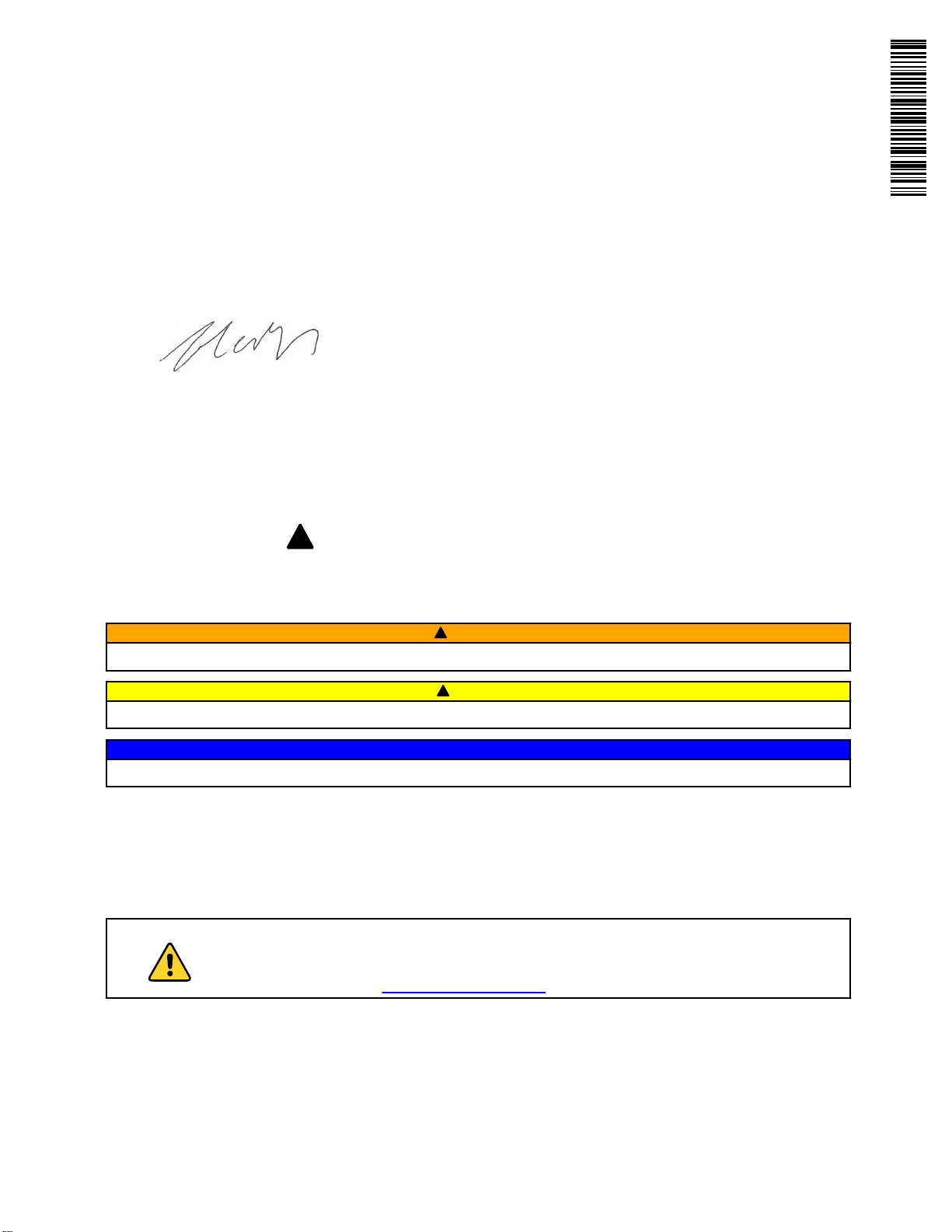
3.0 Liter TDI Front View Components
a - Gear lubrication monitor
b - Engine control module cover
c - Engine oil dipstick
d - Engine coolant expansion
tank
e - Power steering oil reservoir
f - Charge air cooler
(intercooler)
g - Sacrificial anode
h - Seawater inlet connection
i - Seawater pump
j - Seawater‑cooling system
drain screw
k - Closed‑cooling system drain
screw
l - Heat exchanger
m - Alternator
n - Water‑in‑fuel sensor
o - Fuel filter with water sensor
p - Manual fuel primer
3.0 Liter TDI Starboard View Components
a - Engine control module cover
b - Gear lubrication monitor
c - Manual fuel primer
d - Fuel filter with water sensor
e - Water‑in‑fuel sensor
f - Motor mount
g - Starter
h - Air filter
i - Turbocharger
j - Oil filter
k - Oil fill cap
Page 2 90-8M0145546 eng MAY 2018
Page 11
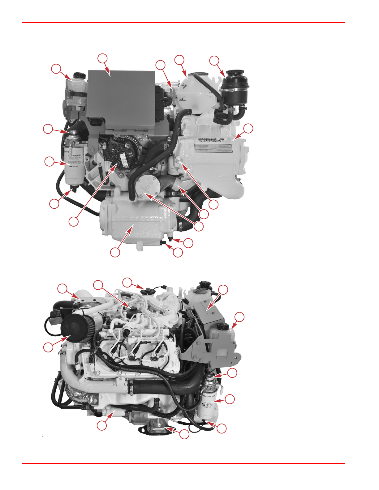
3.0 Liter TDI Port View Components
a
b
c
d
e
f
g
h
i
j
k
l
m
52239
Section 1 - Getting to Know Your Power Package
a - Oil filter
b - Air filter
c - Turbocharger
d - Exhaust pipe
e - Seawater‑cooling drain screw
f - Power steering/gearbox oil
cooler
g - Motor mount
h - Power steering pump
i - Charge air cooler (intercooler)
j - Oil fill cap
k - Power steering oil reservoir
l - Engine coolant expansion
tank
m - Engine control module cover
Features and Controls
TDI 3.0 Liter Engine Features
The Mercury Diesel 3.0 Liter 6‑cylinder engine has the following features:
• Four‑stroke diesel engine
• Common‑rail direct injection
• 6 cylinders (90° V angle)
• 3.0 liter displacement (183.1 cid)
• Crankshaft mounted on four bearings
• 4 valves per cylinder
• Hydraulically adjusted bucket tappets
• Forced‑feed circulatory engine lubrication with geared oil pump and replaceable oil filter in main flow
• Dry air filter
• Turbocharged with variable turbine geometry
• Two separate cooling circuits
• Seawater‑cooled circuit runs through the oil cooler, the main heat exchanger, and the exhaust manifold.
• Closed‑cooling circuit runs coolant as a closed pressurized system through the engine block, oil cooler, exhaust
collector, and after reaching the operating temperature, through the main heat exchanger.
Refer to Specifications for additional details.
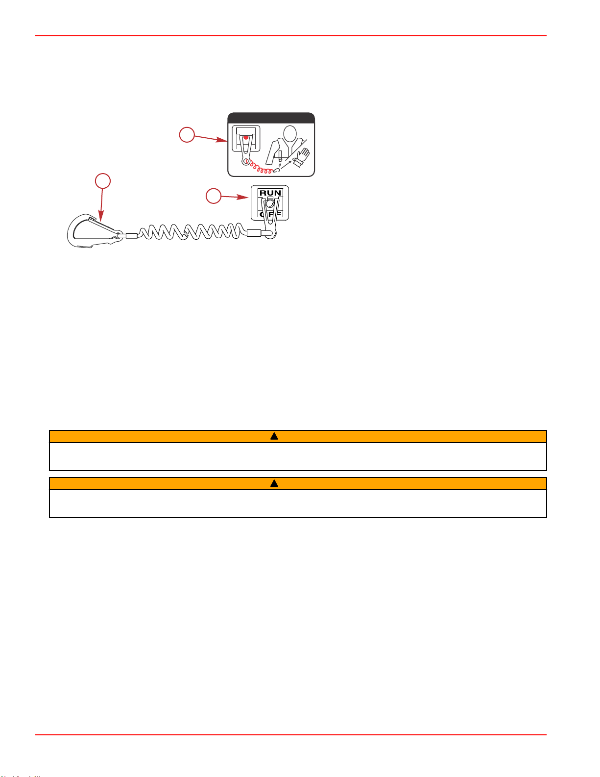
Lanyard Stop Switch
The purpose of a lanyard stop switch is to turn off the engine when the operator moves far enough away from the operator's
position (as in accidental ejection from the operator's position) to activate the switch. Tiller handle outboards and some remote
control units are equipped with a lanyard stop switch. A lanyard stop switch can be installed as an accessory ‑ generally on the
dashboard or side adjacent to the operator's position.
A decal near the lanyard stop switch is a visual reminder for the operator to attach the lanyard to their personal flotation device
(PFD) or wrist.
90-8M0145546 eng MAY 2018 Page 3
Page 12
c
a
b
53910
OFF
RUN
ATTACH LANYARD
Section 1 - Getting to Know Your Power Package
The lanyard cord is usually 122–152 cm (4–5 feet) in length when stretched out, with an element on one end made to be
inserted into the switch and a clip on the other end for attaching to the operator's PFD or wrist. The lanyard is coiled to make its
at‑rest condition as short as possible to minimize the likelihood of lanyard entanglement with nearby objects. Its stretched‑out
length is made to minimize the likelihood of accidental activation should the operator choose to move around in an area close
to the normal operator's position. If it is desired to have a shorter lanyard, wrap the lanyard around the operator's wrist or leg, or
tie a knot in the lanyard.
a - Lanyard cord clip
b - Lanyard decal
c - Lanyard stop switch
Read the following Safety Information before proceeding.
Important Safety Information: The purpose of a lanyard stop switch is to stop the engine when the operator moves far
enough away from the operator's position to activate the switch. This would occur if the operator accidentally falls overboard or
moves within the boat a sufficient distance from the operator's position. Falling overboard and accidental ejections are more
likely to occur in certain types of boats such as low sided inflatables, bass boats, high performance boats, and light, sensitive
handling fishing boats operated by a hand tiller. Falling overboard and accidental ejections are also likely to occur as a result of
poor operating practices such as sitting on the back of the seat or gunwale at planing speeds, standing at planing speeds,
sitting on elevated fishing boat decks, operating at planing speeds in shallow or obstacle infested waters, releasing your grip on
a steering wheel or tiller handle that is pulling in one direction, drinking alcohol or consuming drugs, or daring high speed boat
maneuvers.
While activation of the lanyard stop switch will stop the engine immediately, a boat will continue to coast for some distance
depending upon the velocity and degree of any turn at shut down. However, the boat will not complete a full circle. While the
boat is coasting, it can cause injury to anyone in the boat's path as seriously as the boat would when under power.
We strongly recommend that other occupants be instructed on proper starting and operating procedures should they be
required to operate the engine in an emergency (if the operator is accidentally ejected).
WARNING
!
If the operator falls out of the boat, stop the engine immediately to reduce the possibility of serious injury or death from being
struck by the boat. Always properly connect the operator to the stop switch using a lanyard.
WARNING
!
Avoid serious injury or death from deceleration forces resulting from accidental or unintended stop switch activation. The boat
operator should never leave the operator's station without first disconnecting the stop switch lanyard from the operator.
Accidental or unintended activation of the switch during normal operation is also a possibility. This could cause any, or all, of
the following potentially hazardous situations:
• Occupants could be thrown forward due to unexpected loss of forward motion ‑ a particular concern for passengers in the
front of the boat who could be ejected over the bow and possibly struck by the gearcase or propeller.
• Loss of power and directional control in heavy seas, strong current, or high winds.
• Loss of control when docking.
Keep the Lanyard Stop Switch and Lanyard Cord in Good Operating Condition
Before each use, check to ensure the lanyard stop switch works properly. Start the engine and stop it by pulling the lanyard
cord. If the engine does not stop, have the switch repaired before operating the boat.
Before each use, visually inspect the lanyard cord to ensure it is in good working condition and that there are no breaks, cuts,
or wear to the cord. Check that the clips on the ends of the cord are in good condition. Replace any damaged or worn lanyard
cords.
Page 4 90-8M0145546 eng MAY 2018
Page 13
65505
a
b
c
c
50400
Section 1 - Getting to Know Your Power Package
Instrumentation
VesselView
Your power package may be connected to a SmartCraft VesselView multifunction display. VesselView is a comprehensive boat
information center that can display information for up to four gasoline or diesel engines. It continuously monitors and reports
basic operating data including detailed information such as seawater temperature and depth, trim status, boat speed and
steering angle, and the status of fuel, oil, water, and waste tanks.
VesselView can be fully integrated with a vessel’s global positioning system (GPS) or other NMEA‑compatible devices to
provide up‑to‑the‑minute navigation, speed, and fuel‑to‑destination information.
VesselView Suite
Refer to your VesselView operation manual for detailed instructions on how to operate this display.
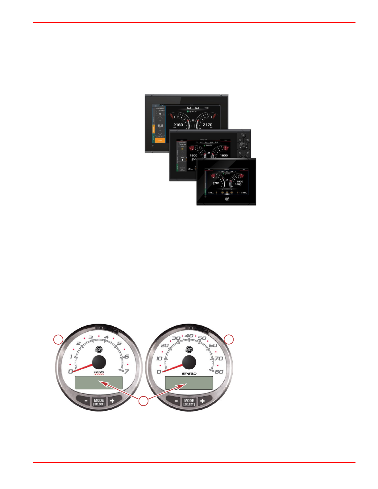
SmartCraft Speedometer, Tachometer, and Digital Gauges
The SmartCraft instrument package augments the information provided by VesselView. The instrument package may display:
• Engine RPM
• Boat speed
• Coolant temperature
• Oil pressure
• Battery voltage
• Fuel consumption
• Engine operating hours
SmartCraft tachometer and speedometer
a - Tachometer
b - Speedometer
c - LCD display
The SmartCraft instrument package also aids in identifying the fault codes associated with the engine audio warning system.
The SmartCraft instrument package displays critical engine alarm data and other potential problems on its LCD display.
For basic operation information on the SmartCraft instrument package and for details on the warning functions monitored by the
system, refer to the manual provided with your gauge package.
90-8M0145546 eng MAY 2018 Page 5
Page 14
abc
d
37925
63723
Section 1 - Getting to Know Your Power Package
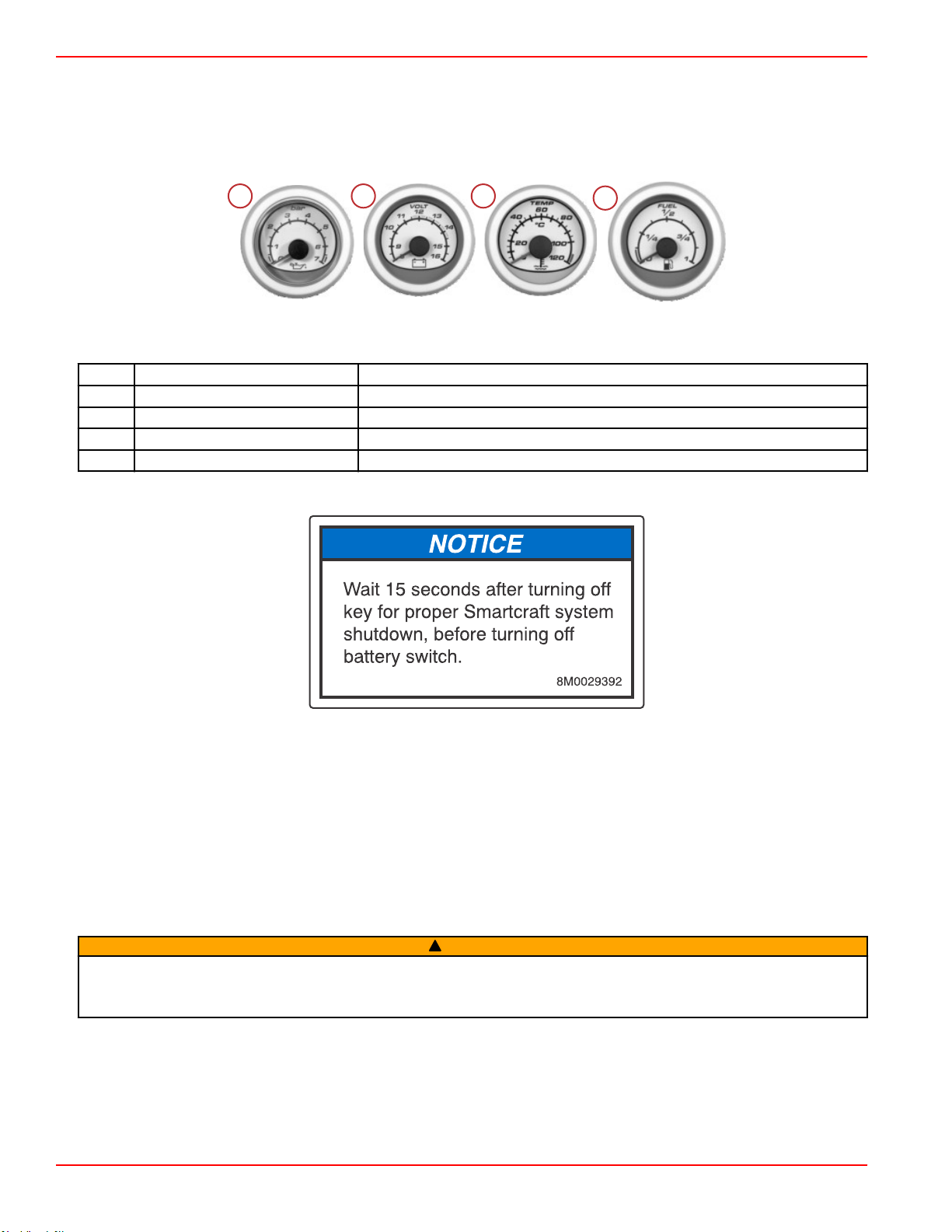
System Link Digital Gauges
Some instrumentation packages include gauges that augment the information provided by VesselView and the SmartCraft
tachometer and speedometer. The owner and operator should be familiar with all the instruments and their functions on the
boat. Have your boat dealer explain the gauges and normal readings that appear for your boat.
The following types of digital gauges may be included with your power package.
System Link digital gauges
Item Gauge Indicates
a Oil pressure gauge Engine oil pressure
b Voltmeter Battery voltage
c Water temperature gauge Engine operating temperature
d Fuel gauge Quantity of fuel in tank
SmartCraft System—Power Shut Down
IMPORTANT: When the key switch is turned off, SmartCraft information is communicated to the TDI vessel adapter assembly.
Allow a minimum of 15 seconds for the communication to be completed before turning the battery switch to the off position or
disconnecting battery power. Failure to allow the communication to be completed, may cause an error message to display on
the SmartCraft device at the next engine start sequence. Waiting 30 seconds before removing battery power will ensure the
communication is unrestricted and thorough. To erase the error message, turn the key switch to the off position and wait one
minute before starting the engine.
Power Trim
Power trim allows the operator to adjust the sterndrive angle while underway to provide the ideal boat angle for varying load
and water conditions. Also, the trailering feature allows the operator to raise and lower the sterndrive for trailering, beaching,
launching, low‑speed (below 1200 RPM engine speed), and shallow water operation.
WARNING
!
Excessive trim can cause serious injury or death at high speeds, and single‑ram trim systems do not provide a trim‑out
limiting device or trim indicator. Use caution when trimming with a single‑ram trim system and never trim out beyond the unit's
side support flanges while the boat is underway or at engine speeds above 1200 RPM.
Page 6 90-8M0145546 eng MAY 2018
Page 15
Section 1 - Getting to Know Your Power Package
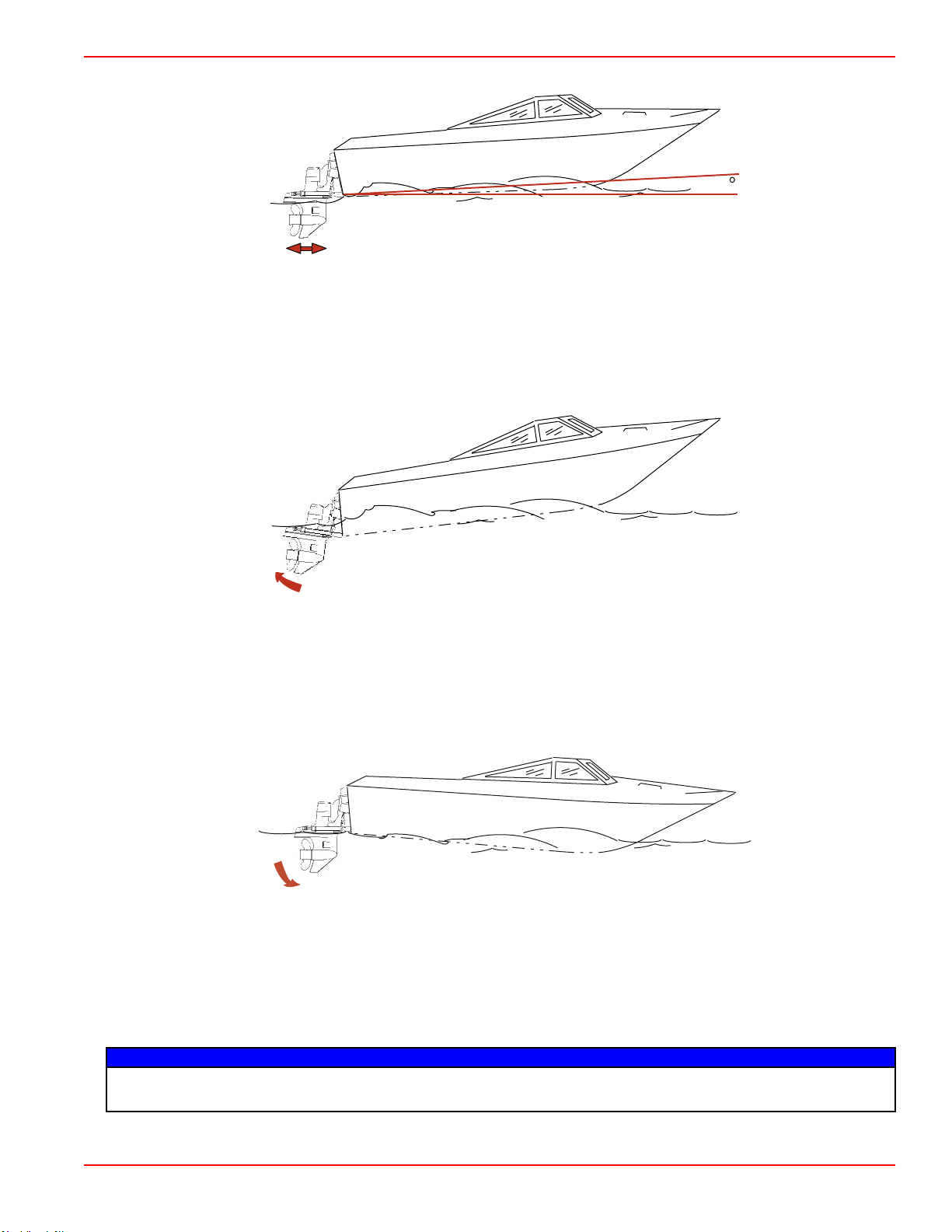
For best performance trim the sterndrive so that the boat bottom is at a 3–5° angle to the water.
3 - 5
mc79528
Trimming the sterndrive up (out) can:
• Generally increase top speed
• Increase clearance over submerged objects or a shallow bottom
• Cause the boat to accelerate and plane off slower
• In excess, cause boat porpoising (bouncing) or propeller ventilation
• Cause engine overheating if trimmed up (out) to a point where any cooling water intake holes are above the waterline
mc78529
Trimming the sterndrive down (in) can:
• Help the boat accelerate and plane off quicker
• Generally improve the ride in choppy water
• In most cases, reduce boat speed
• If in excess, lower the bow of some boats to a point at which they begin to plow with their bow in the water while on plane.
This can result in an unexpected turn in either direction called bow steering or oversteering if any turn is attempted or if a
significant wave is encountered.
mc79530
Single Engine Trim and Trailer
Single engine applications have a button that can be pressed to trim the sterndrive unit up (out) or down (in).
To raise the sterndrive for trailering, beaching, launching, low‑speed (below 1200 RPM), and shallow water operation push the
trim button to raise the sterndrive to the full up (out) position.
Some controls also have a trailer button that trims the sterndrive to a position suitable for trailer purposes only.
Dual Engine Trim and Trailer
NOTICE
If using external tie bars, raising or lowering the drives independently of each other can damage the drive and steering
systems. If using an external tie bar, raise and lower all drives together as a unit.
90-8M0145546 eng MAY 2018 Page 7
Page 16
9208
a
b
a
c
50534
b
Section 1 - Getting to Know Your Power Package
Dual engine applications may have a single integral button to operate both sterndrives simultaneously or may have separate
buttons for each sterndrive.
Some controls also have a trailer button that trims the sterndrives to a position suitable for trailer purposes only.
Power Trim and MerCathode Overload Protection
If an electrical overload on the electrical system occurs, a fuse will open (blow). Find and correct the cause before replacing the
fuse.
NOTE: If you must operate the engine in an emergency, turn off and disconnect all accessories from the engine and
instrumentation wiring if you cannot find and correct the cause for the electrical overload or excessive current draw. Replace
the fuse. If the fuse burns out, the electrical overload has not been eliminated. Further checks must be made on the electrical
system. Contact your Mercury Diesel authorized repair facility.
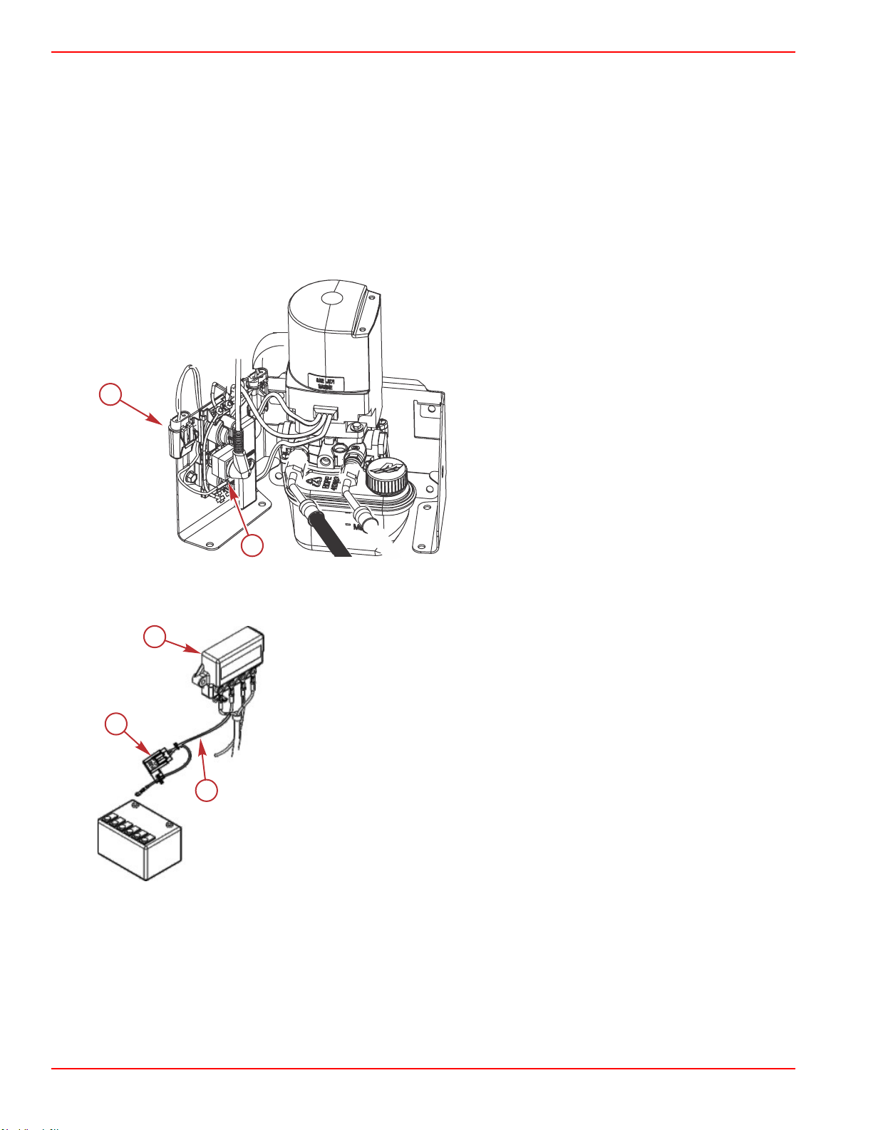
1. The power trim system is protected from overload by a 110‑amp fuse and a 20‑amp in‑line fuse on the power trim pump.
a - 20‑amp in‑line fuse holder
b - 110‑amp fuse
2. There are several different Quicksilver MerCathode systems available. Each has a fuse connected to the positive (+)
terminal on the controller. If the fuse is open (blown), the system will not operate, resulting in a loss of corrosion protection.
Replace the fuse with one of the same amp rating.
a - MerCathode
b - Red/purple wire
c - Fuse
Warning Horn Signals
When the key switch is turned to the on position, the horn will turn on for a moment as a test to indicate the horn is working.
There are two types of warning horns to alert the operator of an active problem within the engine’s operating system.
1.
Continuous six second beep: Indicates a critical engine condition. Depending on the condition, the Engine Guardian
system may engage and protect the engine by limiting power. You should return to port immediately and contact your
servicing dealer.
Page 8 90-8M0145546 eng MAY 2018
Page 17
38160
28082
Section 1 - Getting to Know Your Power Package
2.
Intermittent short beeps for six seconds: Indicates a noncritical engine condition. This condition does not require
immediate attention. You may continue using your boat, however, depending on the nature of the problem, the engine’s
power may be limited by the Engine Guardian system to protect the engine. You should contact your servicing dealer at
your earliest convenience.
It is important to note that in either of the above scenarios, the horn will only sound one time. If you key the engine off and
restart it, the horn will sound again, one time, if the fault is still present.
A few of the noncritical conditions indicated by the intermittent short beeps for six seconds can be corrected by the operator.
These operator correctable conditions are as follows:
•
Water in the fuel filter. Refer to Maintenance – Water‑Separating Fuel Filter.
• Cooling system (water pressure or engine temperature) problem. Stop the engine and check the water intake holes in the
lower unit for obstruction.
•
Low engine oil level. Refer to Maintenance – Engine Oil.
Engine Guardian System
The Engine Guardian system monitors the critical sensors on the engine for any early indications of problems. Engine Guardian
is functional whenever your engine is operating, so you never have to be concerned about whether or not you are protected.
The system will respond to a problem by sounding the warning horn for six seconds and/or reducing engine power in order to
provide engine protection.
If Engine Guardian has been activated, reduce the engine speed. The problem will need to be identified and corrected. The
system must be reset before the engine will operate at higher speeds. Moving the throttle lever back to the idle position will
reset the Engine Guardian system. If the Engine Guardian system has determined the reset has not corrected the problem,
Engine Guardian will remain activated, limiting the throttle. The problem must be identified and corrected before Engine
Guardian will allow the engine to reach a normal operating RPM.
Controls
Switches
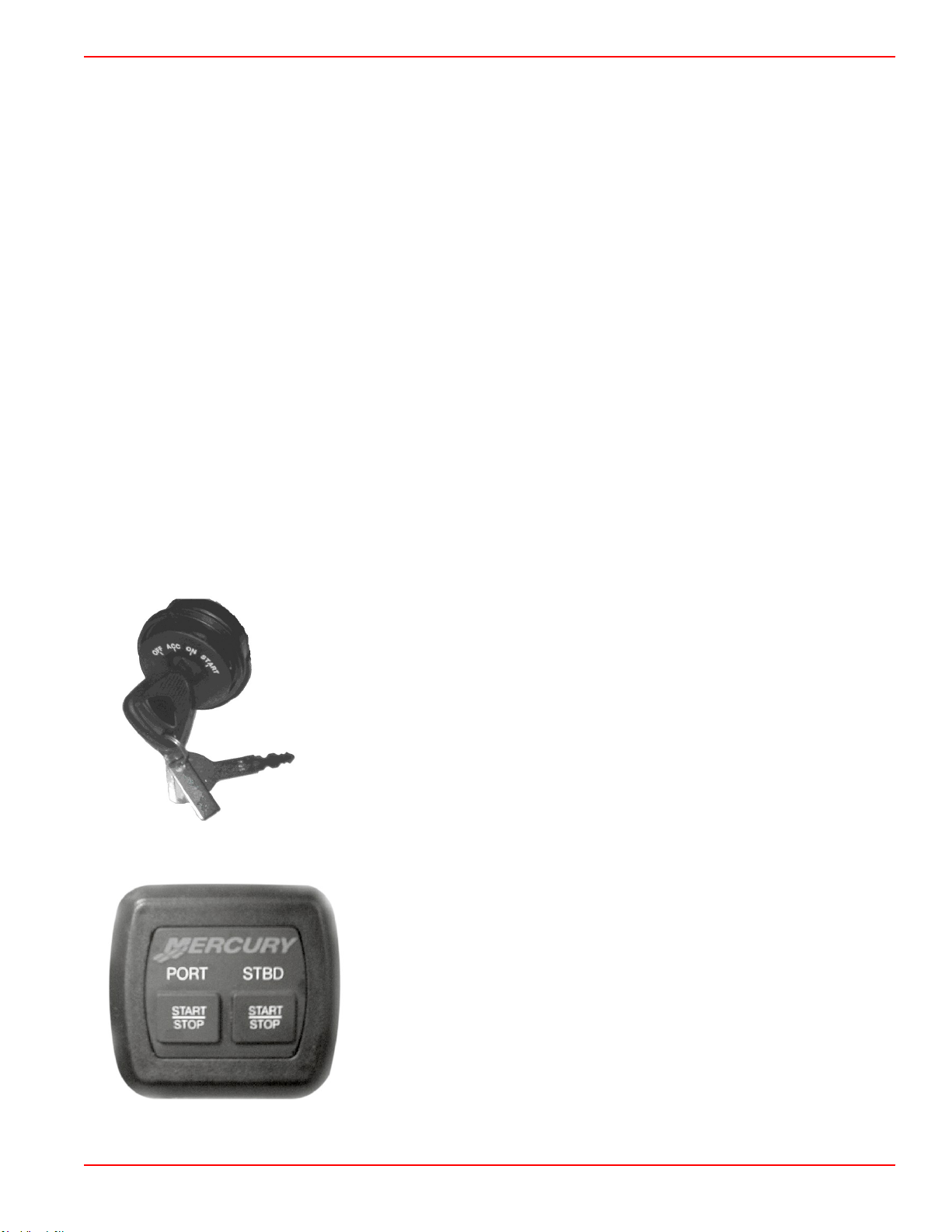
Four‑Position Key Switch
NOTE: The key can only be removed with the key switch in the "OFF" position.
Dual‑Engine Start‑Stop Switch
•
"OFF" ‑ In the "OFF" position, all electrical circuits are off. The engine will not operate with
the key switch in the "OFF" position.
•
"ACC" ‑ In the "ACC" position, any accessories connected to the electrical circuits can be
operated. The engine will not operate with the key switch in the "ACC" position.
•
"ON" ‑ In the "ON" position, all electrical circuits and instrumentation receive power. The
engine can be started with an optional start‑stop switch.
•
"START" ‑ Turn the key to the start position and release to start the engine.
A start‑stop switch is optional equipment. The start‑stop switch works in conjunction
with the key switch. There is one start‑stop switch for each engine. Each button on a
multiengine start‑stop switch functions independently. The key switch must be in the
run position to start a stopped engine with the start‑stop switch. Pressing a start‑stop
switch button when an engine is running will shut down the corresponding engine.
90-8M0145546 eng MAY 2018 Page 9
Page 18
OFF
ON
38277
35308
Section 1 - Getting to Know Your Power Package
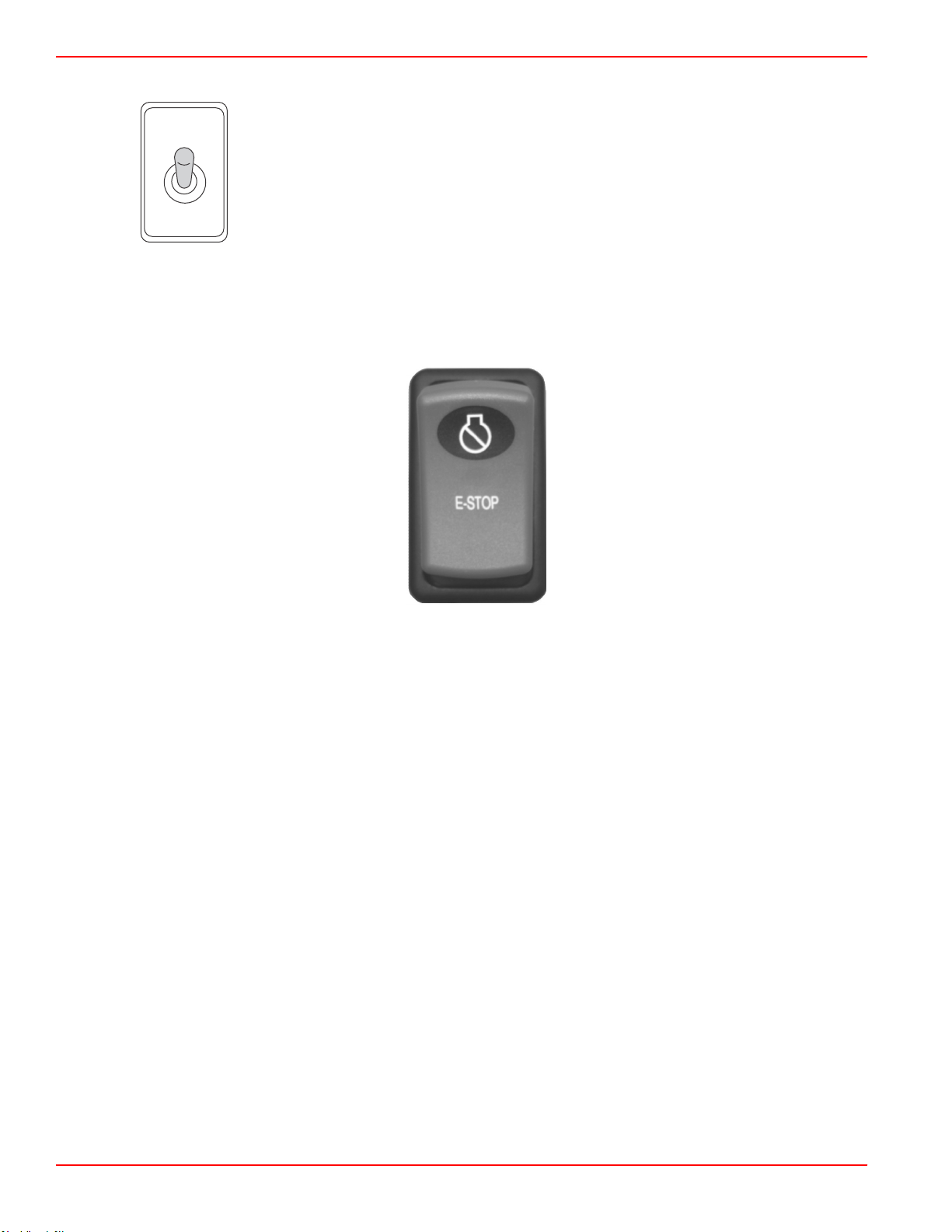
Bilge Blower Toggle Switch
Operates the bilge blower, if equipped.
Emergency Stop Switch
An emergency stop (E‑stop) switch is used to turn off the engines in an emergency situation, such as a person overboard or a
tangled propeller. When activated, an E‑stop switch interrupts the power supply to the engine and transmission. If the boat is
equipped with an E‑stop switch, the E‑stop switch turns off all of the engines.
Typical E-stop switch
Activation of an E‑stop switch stops the engine, or engines, immediately, but the boat can continue to coast for some distance
depending upon the velocity and degree of any turn at shutdown. While the boat is coasting, it can cause injury to anyone in the
boat's path as seriously as the boat would when under power.
We recommend instructing other occupants on proper starting and operating procedures should they need to operate the
engine in an emergency.
Accidental or unintended activation of the switch during normal operation is also possible, which can cause any or all of the
following potentially hazardous situations:
• Occupants can be thrown forward due to unexpected loss of forward motion, and passengers in the front of the boat could
be ejected over the bow and possibly struck by the propulsion or steering components.
• The operator can lose power and directional control in heavy seas, strong current, or high winds.
• The operator can lose control of the vessel when docking.
Restarting an engine using the key switch or start button after an E‑stop shutdown without first turning the key switch to the off
position for at least 30 seconds will restart the engine but cause fault codes to be set. Unless you are in a potentially hazardous
situation, turn the key switch off and wait at least 30 seconds before restarting the engine or engines. If after restarting, some
fault codes are still being displayed, contact your authorized Mercury Diesel repair facility.
Lanyard Stop Switch
The purpose of a lanyard stop switch is to turn off the engine when the operator moves far enough away from the operator's
position (as in accidental ejection from the operator's position) to activate the switch. Tiller handle outboards and some remote
control units are equipped with a lanyard stop switch. A lanyard stop switch can be installed as an accessory ‑ generally on the
dashboard or side adjacent to the operator's position.
A decal near the lanyard stop switch is a visual reminder for the operator to attach the lanyard to their personal flotation device
(PFD) or wrist.
Page 10 90-8M0145546 eng MAY 2018
Page 19
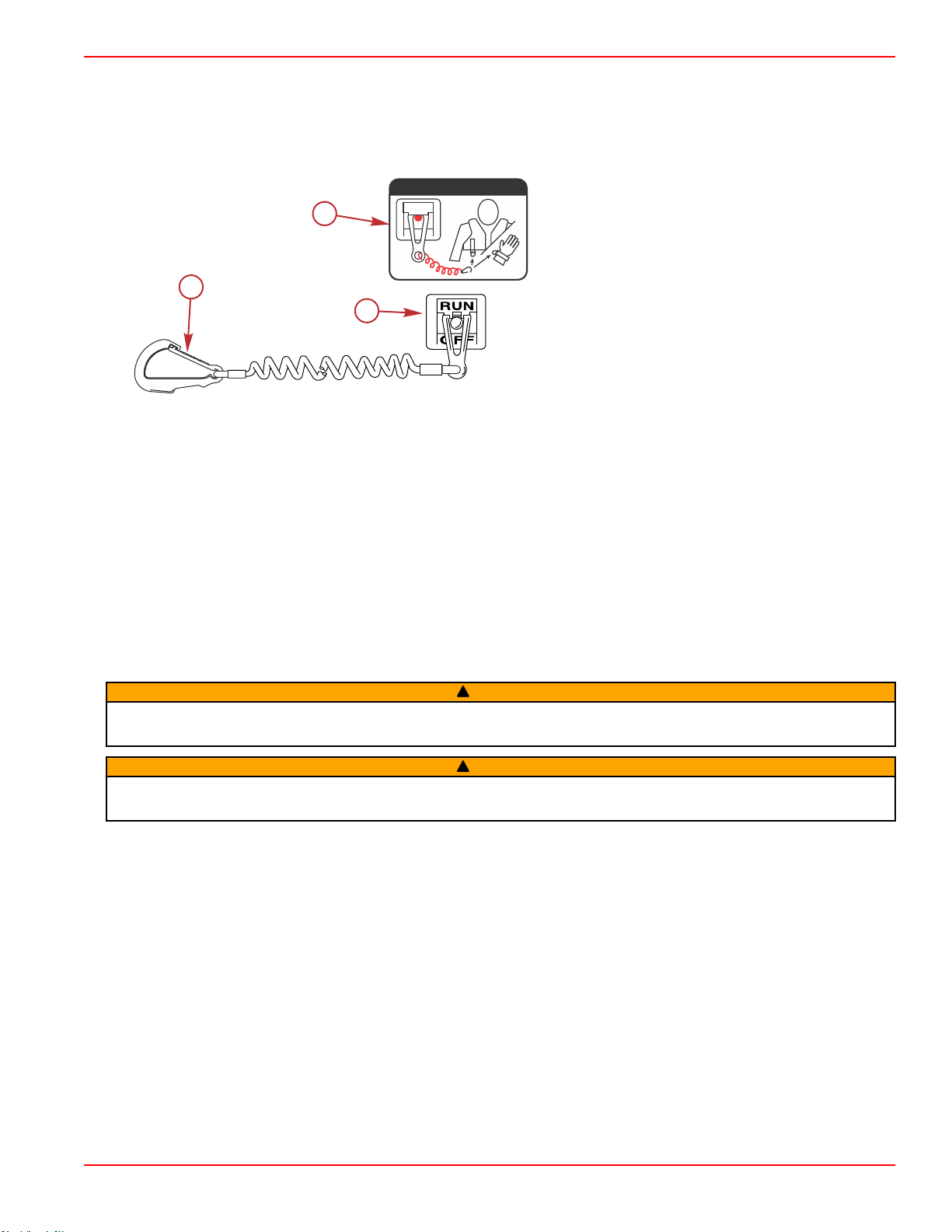
c
a
b
53910
OFF
RUN
ATTACH LANYARD
Section 1 - Getting to Know Your Power Package
The lanyard cord is usually 122–152 cm (4–5 feet) in length when stretched out, with an element on one end made to be
inserted into the switch and a clip on the other end for attaching to the operator's PFD or wrist. The lanyard is coiled to make its
at‑rest condition as short as possible to minimize the likelihood of lanyard entanglement with nearby objects. Its stretched‑out
length is made to minimize the likelihood of accidental activation should the operator choose to move around in an area close
to the normal operator's position. If it is desired to have a shorter lanyard, wrap the lanyard around the operator's wrist or leg, or
tie a knot in the lanyard.
a - Lanyard cord clip
b - Lanyard decal
c - Lanyard stop switch
Read the following Safety Information before proceeding.
Important Safety Information: The purpose of a lanyard stop switch is to stop the engine when the operator moves far
enough away from the operator's position to activate the switch. This would occur if the operator accidentally falls overboard or
moves within the boat a sufficient distance from the operator's position. Falling overboard and accidental ejections are more
likely to occur in certain types of boats such as low sided inflatables, bass boats, high performance boats, and light, sensitive
handling fishing boats operated by a hand tiller. Falling overboard and accidental ejections are also likely to occur as a result of
poor operating practices such as sitting on the back of the seat or gunwale at planing speeds, standing at planing speeds,
sitting on elevated fishing boat decks, operating at planing speeds in shallow or obstacle infested waters, releasing your grip on
a steering wheel or tiller handle that is pulling in one direction, drinking alcohol or consuming drugs, or daring high speed boat
maneuvers.
While activation of the lanyard stop switch will stop the engine immediately, a boat will continue to coast for some distance
depending upon the velocity and degree of any turn at shut down. However, the boat will not complete a full circle. While the
boat is coasting, it can cause injury to anyone in the boat's path as seriously as the boat would when under power.
We strongly recommend that other occupants be instructed on proper starting and operating procedures should they be
required to operate the engine in an emergency (if the operator is accidentally ejected).
WARNING
!
If the operator falls out of the boat, stop the engine immediately to reduce the possibility of serious injury or death from being
struck by the boat. Always properly connect the operator to the stop switch using a lanyard.
WARNING
!
Avoid serious injury or death from deceleration forces resulting from accidental or unintended stop switch activation. The boat
operator should never leave the operator's station without first disconnecting the stop switch lanyard from the operator.
Accidental or unintended activation of the switch during normal operation is also a possibility. This could cause any, or all, of
the following potentially hazardous situations:
• Occupants could be thrown forward due to unexpected loss of forward motion ‑ a particular concern for passengers in the
front of the boat who could be ejected over the bow and possibly struck by the gearcase or propeller.
• Loss of power and directional control in heavy seas, strong current, or high winds.
• Loss of control when docking.
Keep the Lanyard Stop Switch and Lanyard Cord in Good Operating Condition
Before each use, check to ensure the lanyard stop switch works properly. Start the engine and stop it by pulling the lanyard
cord. If the engine does not stop, have the switch repaired before operating the boat.
Before each use, visually inspect the lanyard cord to ensure it is in good working condition and that there are no breaks, cuts,
or wear to the cord. Check that the clips on the ends of the cord are in good condition. Replace any damaged or worn lanyard
cords.
90-8M0145546 eng MAY 2018 Page 11
Page 20
a
b
bcd
51014
a
b
28619
Section 1 - Getting to Know Your Power Package
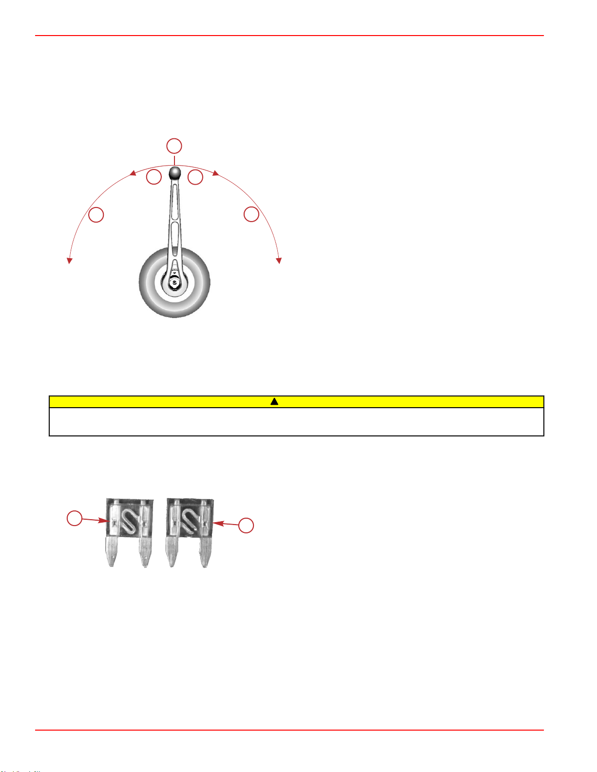
Remote Control
Remote Control Function
Operation of the throttle and shift are controlled by the movement of the control handle. Push the control handle forward from
neutral with a quick firm motion to the first detent for forward gear. Continue pushing forward to increase the engine RPM. Pull
the control handle back from neutral with a quick firm motion to the first detent for reverse gear and continue pulling back to
increase the engine RPM.
The remote control handle must be in the neutral position to start the engine.
a - Neutral
b - Increase engine RPM
c - Forward gear
d - Reverse gear
Digital Throttle and Shift
Digital Throttle and Shift (DTS) operating instructions are provided in a separate manual. Refer to Mercury Diesel's SmartCraft
and DTS Operator's Manual.
Electrical System Overload Protection
!
CAUTION
Failure to protect wiring with an appropriate fuse can damage the wiring and start a fire. When installing any accessories, we
recommend using a Mercury accessory kit. Always use the appropriate fuse to protect wiring.
Fuses
Fuses protect individual circuits from an overload. If an electrical overload occurs, a fuse will burn out. Find and correct the
cause for the electrical overload before replacing the fuse. Always replace a burned out fuse with a fuse that is the same
current rating. Never install a higher current rated fuse.
Identifying a burned out fuse
a - Good fuse
b - Burned out fuse
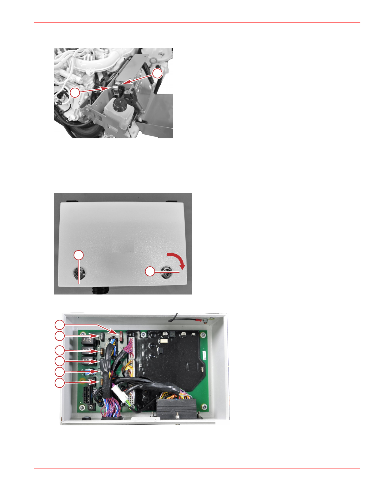
Two fuses are located on the engine. To access these fuses, remove the two screws securing the engine control module cover.
Be certain to replace an open fuse only with one of the same current rating.
Page 12 90-8M0145546 eng MAY 2018
Page 21
52530
a
b
a
b
52444
a
b
c
d
e
f
52510
Section 1 - Getting to Know Your Power Package
The remaining fuses are located in the vessel adapter assembly (refer to your boat owner's manual for location) and on the rear
side of the control unit of the individual instrumentation.
Engine control module
a - 25‑amp fuse
b - 15‑amp fuse
Vessel Adapter Assembly (VAA) Fuse Replacement
NOTE: Refer to your boat owner's manual for the location of the vessel adapter assembly (VAA). The key for the VAA was
provided along with the ignition keys.
1. Verify the ignition key is off and the lanyard switch is off.
2. Insert the key into the lock and turn it 1/4 turn to the right to unlock it.
Vessel adapter assembly
a - Locked
b - Unlocked
3. Lift the cover. A decal on the cover identifies components and fuses inside the VAA.
a - Helm power 5‑amp fuse
b - EFP 1‑amp fuse
c - Feature A 1‑amp fuse
d - T.15 5‑amp fuse
e - Feature B 1‑amp fuse
f - Main power 10‑amp fuse
4. Replace the open fuse with a new fuse of the same current rating.
5. Close and lock the cover to prevent water intrusion and an accidental short circuit.
90-8M0145546 eng MAY 2018 Page 13
Page 22
25986
a
52079
Section 1 - Getting to Know Your Power Package
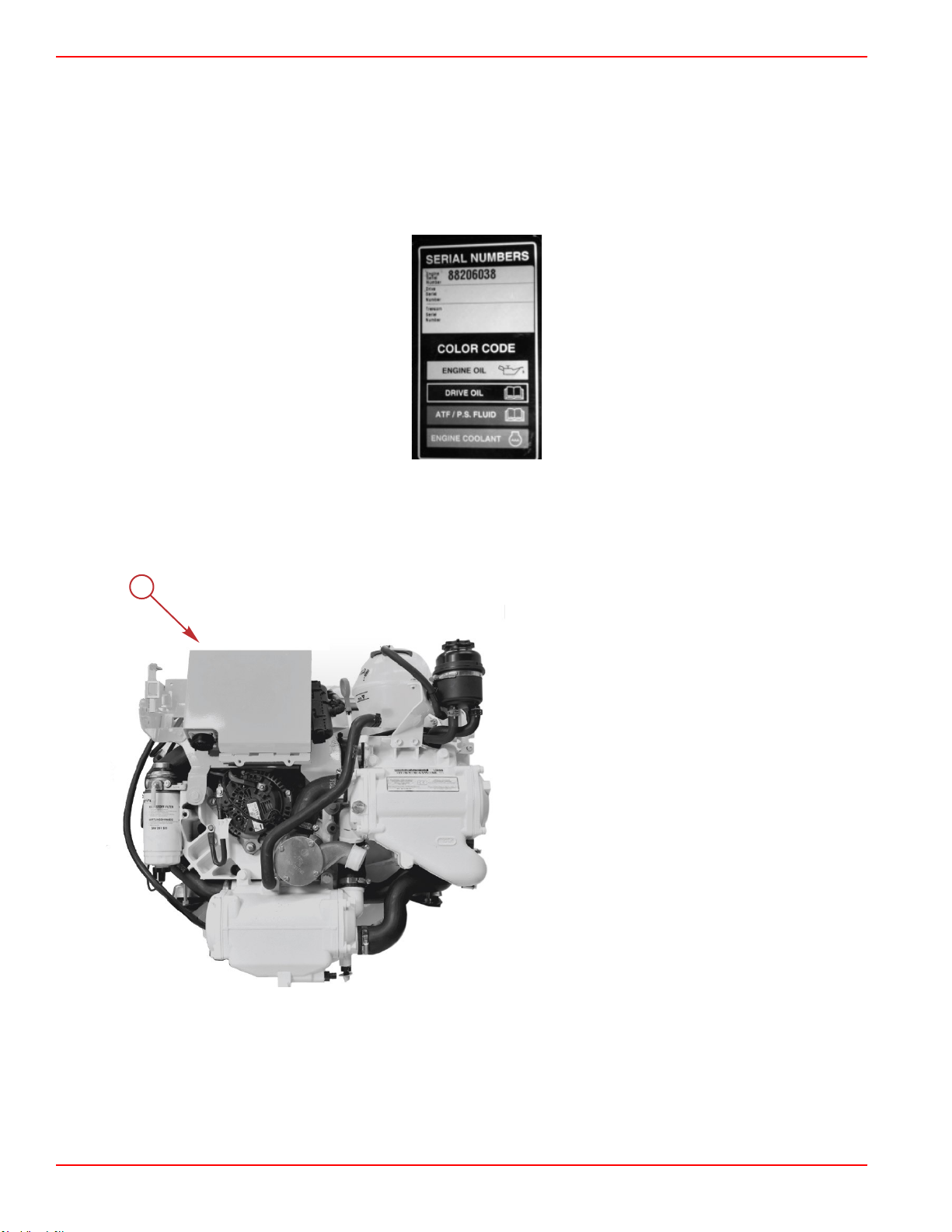
Identification
Serial Number Decal Placement
Three sets of engine, transom assembly, and sterndrive serial number decal strips are provided with each power package. One
set should be used for each of the following:
• Engine specification decal
• Warranty registration card
• Operation and Maintenance Manual identification page.
Engine specification and serial number decal
Engine Data Label Location
The engine data label is located on top of the electrical box.
a - Engine data label (not seen—on top of the
electrical box)
Page 14 90-8M0145546 eng MAY 2018
Page 23
33533
33534
51170
a
Section 1 - Getting to Know Your Power Package
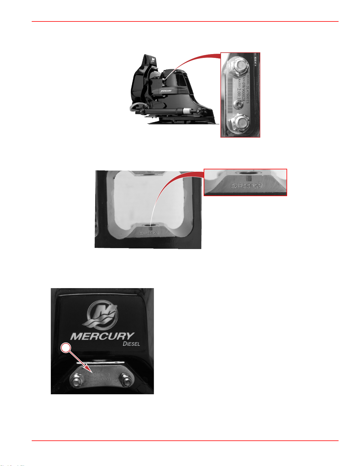
Bravo Sterndrive Serial Number and Identification
The Bravo sterndrive serial number, gear ratio, model number, and bar code are embedded in the ground plate on the port side
of the sterndrive.
Bravo sterndrive information on ground plate
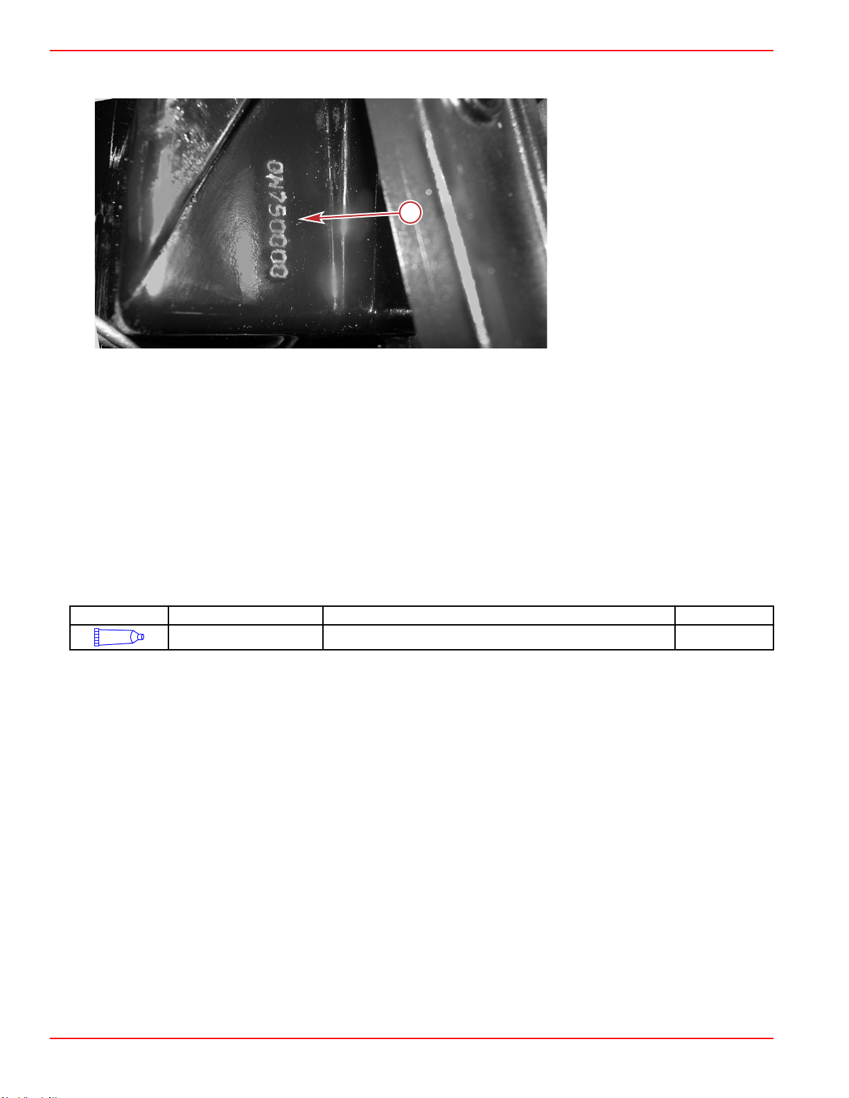
The serial number is also stamped as a permanent reference on the sterndrive casting inside the back cover.
Bravo sterndrive serial number stamping
Bravo Transom Serial Number
The Bravo transom serial number is stamped in the U‑bolt plate of the Bravo transom assembly.
Bravo transom assembly U-bolt plate
a - Transom assembly serial number
90-8M0145546 eng MAY 2018 Page 15
Page 24
25905
a
Section 1 - Getting to Know Your Power Package
The serial number is also stamped on the gimbal housing. This is used as a permanent reference for Mercury Diesel authorized
repair facilities.
Gimbal housing with serial
number stamping
a - Transom assembly serial
number
SeaCore Equipped Drives
SeaCore Components and Castings
Mercury MerCruiser SeaCore power packages are equipped with additional stainless steel components and particular
aluminum castings with special coatings. Do not replace SeaCore components with non‑SeaCore. Use only the specified
Mercury MerCruiser SeaCore components and castings on these power packages.
Stainless Steel Fasteners
SeaCore models are equipped with additional stainless steel fasteners to maximize corrosion resistance in saltwater
environments.
Stainless steel fasteners are subject to galling when installed without lubrication. Galling can result in fastener destruction,
improper clamp loads, or both. Galled fasteners may appear to torque properly, but still have incorrect clamp loads.
Apply lubricant 2‑4‑C with PTFE or an equivalent, on the threads of stainless steel fasteners during installation to avoid galling.
Lubricate at least the first 8 mm (1/4 in.) of the threads before installation.
Tube Ref No.
95
2-4-C with PTFE Threads of stainless steel fasteners 92-802859A 1
Description Where Used Part No.
Page 16 90-8M0145546 eng MAY 2018
Page 25
xxxxxxxxx
x.x
x x
52250
xxxxxxxxx
Section 1 - Getting to Know Your Power Package
Emissions Information
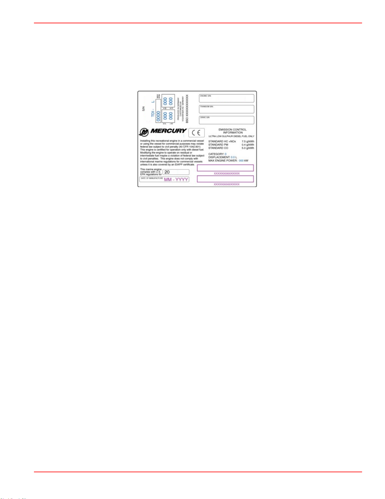
Exhaust Gas Emissions Certificate (Europe Only)
A tamper‑resistant label is affixed to the engine at time of manufacture. In addition to the required exhaust gas emissions
certificate number, the label lists the engine serial number, engine family, maximum RPM, engine power, and weight. Note that
the exhaust gas emissions certification will not affect the fit, function, or performance of the engines. Boatbuilders and dealers
may not remove the label or the part it is affixed to before sale. If modifications are necessary, contact Mercury Diesel about the
availability of replacement decals before proceeding.
Owner Responsibility
The owner or operator is not to modify the engine in any manner that would alter the horsepower or allow exhaust gas emission
levels to exceed their predetermined factory specifications.
90-8M0145546 eng MAY 2018 Page 17
Page 26

Section 1 - Getting to Know Your Power Package
Notes:
Page 18 90-8M0145546 eng MAY 2018
Page 27

Table of Contents
Section 2 - On The Water
Section 2 - On The Water
Safe Boating Recommendations.......................................... 20
Carbon Monoxide Exposure................................................. 21
Be Alert To Carbon Monoxide Poisoning ..................... 21
Stay Clear of Exhaust Areas ........................................ 21
Good Ventilation .......................................................... 21
Poor Ventilation ........................................................... 22
Basic Boat Operation............................................................ 22
Duty Cycle Rating ......................................................... 22
Pleasure Duty Rating ............................................ 22
TDI Operation Chart............................................................. 24
Drain Plug and Bilge Pump.................................................. 24
Starting, Shifting, and Stopping............................................ 24
Before Starting the Engine.............................................25
Starting a Cold Engine................................................... 25
Engine Warm‑Up........................................................... 25
Starting a Warm Engine ................................................26
Shifting........................................................................... 26
Engine Shut Down (Stopping)....................................... 26
Starting the Engine After Stopped While in Gear.......... 26
Trailering the Boat................................................................ 26
Freezing Temperature and Cold Weather Operation........... 27
Protecting People In The Water........................................... 27
Protecting People in the Water...................................... 27
While You Are Cruising ......................................... 27
While Boat Is Stationary ........................................ 27
High Speed and High Performance............................... 27
Passenger Safety in Pontoon Boats and Deck Boats....28
Boats Having an Open Front Deck ........................ 28
Boats with Front‑Mounted, Raised‑Pedestal Fishing
Seats ..................................................................... 28
Wave and Wake Jumping..................................................... 28
Impact with Underwater Hazards......................................... 29
Conditions Affecting Operation............................................. 29
Weight Distribution (Passengers and Gear) Inside the
Boat............................................................................... 29
Bottom of Boat............................................................... 29
Cavitation....................................................................... 30
Ventilation...................................................................... 30
Elevation and Climate.................................................... 30
Propeller Selection.........................................................30
Break‑In................................................................................ 31
Initial Break‑In Procedure.............................................. 31
Sterndrive 10‑Hour Break‑In Period (New or With
Replacement Gears)......................................................31
Engine Break‑In............................................................. 31
20‑Hour Break‑In Period ....................................... 31
After the 20‑Hour Break‑In Period ......................... 31
End of First Season Checkup........................................ 31
2
90-8M0145546 eng MAY 2018 Page 19
Page 28

Section 2 - On The Water
Safe Boating Recommendations
To safely enjoy the waterways, familiarize yourself with local and all other governmental boating regulations and restrictions
and consider the following suggestions.
Know and obey all nautical rules and laws of the waterways.
• We recommend that all powerboat operators complete a boating safety course. In the U.S., the U.S. Coast Guard Auxiliary,
the Power Squadron, the Red Cross, and your state or provincial boating law enforcement agency provide courses. For
more information in the U.S., call the Boat U.S. Foundation at 1‑800‑336‑BOAT (2628).
Perform safety checks and required maintenance.
• Follow a regular schedule and ensure that all repairs are properly made.
Check safety equipment onboard.
• Here are some suggestions of the types of safety equipment to carry when boating:
Approved fire extinguishers
Signal devices: flashlight, rockets or flares, flag, and whistle or horn
Tools necessary for minor repairs
Anchor and extra anchor line
Manual bilge pump and extra drain plugs
Drinking water
Radio
Paddle or oar
Spare propeller, thrust hubs, and an appropriate wrench
First aid kit and instructions
Waterproof storage containers
Spare operating equipment, batteries, bulbs, and fuses
Compass and map or chart of the area
Personal flotation device (one per person onboard)
Watch for signs of weather change and avoid foul weather and rough‑sea boating.
Tell someone where you are going and when you expect to return.
Passenger boarding.
• Stop the engine whenever passengers are boarding, unloading, or are near the back (stern) of the boat. Shifting the drive
unit into neutral is not sufficient.
Use personal flotation devices.
• Federal law requires that there be a U.S. Coast Guard‑approved life jacket (personal flotation device), correctly sized and
readily accessible for every person onboard, plus a throwable cushion or ring. We strongly advise that everyone wear a life
jacket at all times while in the boat.
Prepare other boat operators.
• Instruct at least one person onboard in the basics of starting and operating the engine and boat handling in case the driver
becomes disabled or falls overboard.
Do not overload your boat.
• Most boats are rated and certified for maximum load (weight) capacities (refer to your boat's capacity plate). Know your
boat's operating and loading limitations. Know if your boat will float if it is full of water. When in doubt, contact your
authorized Mercury Marine dealer or the boat manufacturer.
Ensure that everyone in the boat is properly seated.
• Do not allow anyone to sit or ride on any part of the boat that was not intended for such use. This includes the backs of
seats, gunwales, transom, bow, decks, raised fishing seats, and any rotating fishing seat. Passengers should not sit or ride
anywhere that sudden unexpected acceleration, sudden stopping, unexpected loss of boat control, or sudden boat
movement could cause a person to be thrown overboard or into the boat. Ensure that all passengers have a proper seat
and are in it before any boat movement.
Never operate a boat while under the influence of alcohol or drugs. It is the law.
• Alcohol or drugs can impair your judgment and greatly reduce your ability to react quickly.
Know your boating area and avoid hazardous locations.
Page 20 90-8M0145546 eng MAY 2018
Page 29
41127
co
co
co
co
co
co
co
co
co
co
co
co
co
co
co
co
co
co
co
co
43367
Section 2 - On The Water
Be alert.
• The operator of the boat is responsible by law to maintain a proper lookout by sight and hearing. The operator must have
an unobstructed view particularly to the front. No passengers, load, or fishing seats should block the operator's view when
the boat is above idle or planing transition speed. Watch out for others, the water, and your wake.
Never drive your boat directly behind a water‑skier.
• Your boat traveling at 40 km/h (25 mph) will overtake a fallen skier who is 61 m (200 ft) in front of you in five seconds.
Watch fallen skiers.
• When using your boat for waterskiing or similar activities, always keep a fallen or down skier on the operator's side of the
boat while returning to attend to the skier. The operator should always have the down skier in sight and never back up to
the skier or anyone in the water.
Report accidents.
• Boat operators are required by law to file a boating accident report with their state boating law enforcement agency when
their boat is involved in certain boating accidents. A boating accident must be reported if 1) there is loss of life or probable
loss of life, 2) there is personal injury requiring medical treatment beyond first aid, 3) there is damage to boats or other
property where the damage value exceeds $500.00, or 4) there is complete loss of the boat. Seek further assistance from
local law enforcement.
Carbon Monoxide Exposure
Be Alert To Carbon Monoxide Poisoning
Carbon monoxide (CO) is a deadly gas that is present in the exhaust fumes of all internal combustion engines, including the
engines that propel boats, and the generators that power boat accessories. By itself, CO is odorless, colorless, and tasteless,
but if you can smell or taste engine exhaust, you are inhaling CO.
Early symptoms of carbon monoxide poisoning, which are similar to the symptoms of seasickness and intoxication, include
headache, dizziness, drowsiness, and nausea.
WARNING
!
Inhaling engine exhaust gases can result in carbon monoxide poisoning, which can lead to unconsciousness, brain damage,
or death. Avoid exposure to carbon monoxide.
Stay clear from exhaust areas when engine is running. Keep the boat well‑ventilated while at rest or underway.
Stay Clear of Exhaust Areas
Engine exhaust gases contain harmful carbon monoxide. Avoid areas of concentrated engine exhaust gases. When engines
are running, keep swimmers away from the boat, and do not sit, lie, or stand on swim platforms or boarding ladders. While
underway, do not allow passengers to be positioned immediately behind the boat (platform dragging, teak/body surfing). This
dangerous practice not only places a person in an area of high engine exhaust concentration, but also subjects them to the
possibility of injury from the boat propeller.
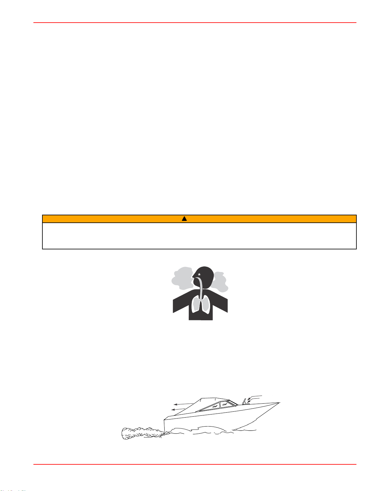
Good Ventilation
Ventilate the passenger area, open side curtains or forward hatches to remove fumes.
Example of desired air flow through the boat:
90-8M0145546 eng MAY 2018 Page 21
Page 30
21626
a
b
a
b
43368
Section 2 - On The Water
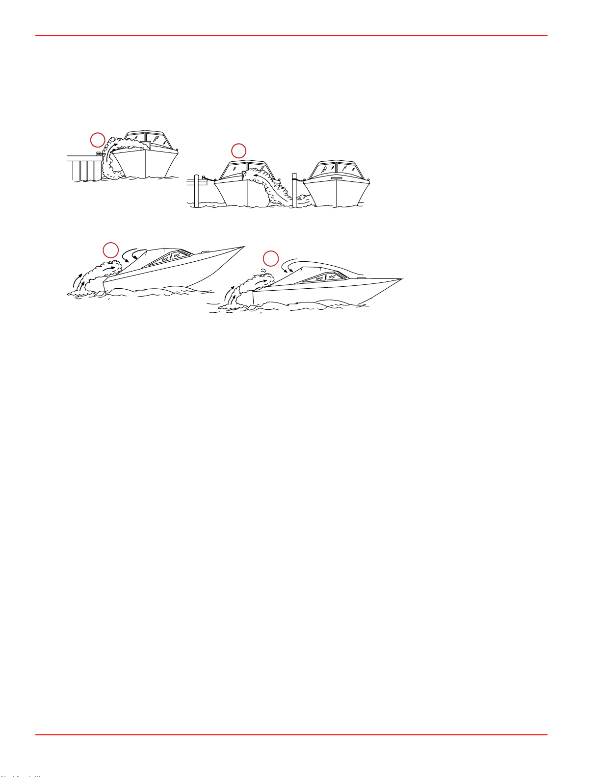
Poor Ventilation
Under certain running or wind conditions, permanently enclosed or canvas enclosed cabins or cockpits with insufficient
ventilation may draw in carbon monoxide. Install one or more carbon monoxide detectors in your boat.
Although the occurrence is rare, on a very calm day, swimmers and passengers in an open area of a stationary boat that
contains or is near a running engine may be exposed to a hazardous level of carbon monoxide.
1. Examples of poor ventilation while the boat is stationary:
a - Operating the engine when the boat
is moored in a confined space
b - Mooring close to another boat that
has its engine operating
2. Examples of poor ventilation while the boat is moving:
a - Operating the boat with the
trim angle of the bow too
high
b - Operating the boat with no
forward hatches open
(station wagon effect)
Basic Boat Operation
IMPORTANT: Always check to ensure the bilge drain plug is installed before launching the boat.
Duty Cycle Rating
IMPORTANT: Damage caused by improper application or failure to operate the power package within the specified operating
parameters will not be covered by the Mercury Diesel Limited Warranty.
It is the responsibility of the boat manufacturer or the installing dealer to ensure that the power package is properly applied. In
all cases, the power package must be equipped with the gear ratio that allows the engine to operate at wide‑open throttle
(WOT) at the rated engine RPM. The power package must also be applied in accordance with recommendations indicated in
the appropriate applications manual. Use of Mercury Diesel engines in other than the applications indicated by the following
information and in the appropriate applications manual requires written approval from an authorized Mercury Diesel application
engineer.
Pleasure Duty Rating
The pleasure duty rating applies to recreational planing craft used exclusively for pleasure and recreation. Typical applications
include pleasure craft such as sailboats, ski boats, runabouts, speedboats, and other planing hulls. Application must conform to
the Pleasure Craft/Recreational duty cycle shown (EPA Mode Number Cycle 5 Duty Cycle).
Page 22 90-8M0145546 eng MAY 2018
Page 31

Section 2 - On The Water
EPA Mode Number
Cycle 5
DUTY CYCLE
Engine speed (percent of WOT) 100 91 80 63 Idle
Engine power (percent of total) 100 75 50 25 0
Time at given mode
(percent of total operating time)
1
5
2
3
4
14584
Chart showing full power operation is limited to a maximum of 1 of 12 hours
1 - Mode 1: 1.0 hour (8%)
2 - Mode 2: 1.5 hours (13%)
3 - Mode 3: 2.0 hours (17%)
4 - Mode 4: 4.0 hours (32%)
5 - Mode 5: 3.5 hours (30%)
1 2 3 4 5
8 13 17 32 30
MODES
90-8M0145546 eng MAY 2018 Page 23
Page 32

Section 2 - On The Water
TDI Operation Chart
Starting Procedure After Starting While Underway Stopping and Shutdown
Open the engine hatch. Air
out the bilge completely.
Turn the battery switch on, if
equipped.
Turn on and run the engine
compartment bilge blower, if
equipped, for five minutes.
Check for leaks: fuel, oil,
water, fluid, etc.
Open the fuel shut‑off valve,
if equipped.
Open the seacock, if
equipped.
Prime the fuel injection
system, if necessary.
Turn the key switch to the
run position and check that
the lights and indicator
lamps come on.
Turn the key switch to the
start position. Release the
key when the engine starts.
Check that the charge
indicator and oil pressure
indicator lamps are off after
engine starts.
Warm‑up the engine at a
fast idle‑RPM for several
minutes.
Observe all gauges and
indicator lamps to check the
condition of the engine. If not
normal, stop the engine.
Check for fuel, oil, water, fluid,
and exhaust leaks, etc.
Check the shift and throttle
control operation.
Check the steering operation.
Verify there are no faults.
Frequently observe all gauges
and indicator lamps to monitor
engine condition.
Listen for the audio alarm.
Shift the remote control lever
to the neutral position.
Run the engine at idle‑RPM
for several minutes to allow
the turbocharger and engine
to cool.
Turn the key switch to the off
position.
Turn the battery switch off, if
equipped.
Close the fuel shut‑off valve, if
equipped.
Close the seacock, if
equipped.
Flush the seawater cooling
circuit, if operating in
saltwater, brackish water, or
polluted water.
Drain Plug and Bilge Pump
The engine compartment in your boat is a natural place for water to collect. For this reason, boats are normally equipped with a
drain plug or a bilge pump. It is very important to check these items on a regular basis to ensure that the water level does not
come into contact with your power package. Components on your engine will be damaged if submerged. Damage caused by
submersion is not covered by the warranty.
Starting, Shifting, and Stopping
WARNING
!
Vapors can ignite and cause an explosion, resulting in engine damage or severe personal injury. Do not use volatile starting
aids such as ether, propane, or gasoline in the engine air intake system.
WARNING
!
Fuel vapors trapped in the engine compartment may be an irritant, cause difficulty breathing, or may ignite resulting in a fire
or explosion. Always ventilate the engine compartment before servicing the power package.
Page 24 90-8M0145546 eng MAY 2018
Page 33

Section 2 - On The Water
Before Starting the Engine
NOTICE
Without sufficient cooling water, the engine, the water pump, and other components will overheat and suffer damage. Provide
a sufficient supply of water to the water inlets during operation.
IMPORTANT: Observe the following before starting:
•
Provide water to the seawater pickup pump.
•
Never operate the starter motor longer than 15 seconds at a time to avoid overheating the starter motor. If the
engine does not start, wait one minute to allow the starter motor to cool; then, repeat the starting procedure.
•
Ensure that the engine crankcase is filled to the correct level with the proper grade of oil for the prevailing
temperature. Refer to Specifications—Engine Oil.
•
Ensure that all electrical connections are secure.
•
Check all items listed in the Maintenance Schedule and Operation Chart.
•
Perform any other necessary checks as indicated by your Mercury Diesel authorized repair facility or specified in
your boat owner’s manual.
Starting a Cold Engine
IMPORTANT: Check the fluid levels before starting the engine. Refer to Maintenance.
1. Turn on and run the engine compartment bilge blower (if equipped) for five minutes. Or, open the engine hatch to air out
the bilge before attempting to start the engine.
2. Place the sterndrive in the full down (in) position.
3. Place the control handle in neutral.
NOTE: The fuel delivery pump is equipped with a priming lever to assist in filling the fuel filter or fuel system. The fuel
delivery pump priming lever can be moved up and down repeatedly in the event that the hand pump and primer plunger on
the fuel filter header is not used to fill the system.
4. If the engine has not been run for a period of time and will not readily start with the standard starting procedure, use the
hand pump and primer plunger located on the fuel filter header. Move the primer plunger (or the priming lever on the fuel
delivery pump) up and down four or five strokes. Attempt to start the engine following the normal procedure.
5. Turn the key switch to the "RUN" position. Observe the indicator lamp for the glow plugs, if equipped. When the cylinder
temperature is great enough to sustain combustion, the indicator lamp will go off and the engine can be started.
NOTICE
Engaging the starter motor while the engine is operating can damage the starter motor or flywheel. Do not engage the starter
motor continually for longer than 15 seconds. Do not engage the starter motor when the engine is operating.
6. Turn the key switch to the "START" position. Release the key and allow the switch to return to the "RUN" position when the
engine starts.
IMPORTANT: Within seconds after starting the engine, the oil pressure should exceed 10 psi (69 kPa) minimum. If the oil
pressure does not meet these minimum limits, stop the engine then locate and correct the problem. If you are unable to
determine the problem, see your Mercury Diesel authorized repair facility.
7. Ensure that the charge indicator and oil pressure warning lamps are off.
8. Ensure that all instrumentation is functioning properly and indicating normal readings.
Engine Warm‑Up
1. After starting the engine, verify that all instrumentation is functioning properly.
2. Operate the engine at 1000–1200 RPM until the engine temperature is within the normal operating range. It is important
that any engine be warmed up before applying full load. The warm‑up period provides time for the lubricating oil to
establish a film between moving parts.
NOTICE
Engine wear caused by increased friction and limited oil flow is greatest when an engine is cold. Decrease engine wear by
allowing the engine coolant temperature to reach normal operating range before hard acceleration or applying full throttle.
3. After the engine has reached operating temperature:
a.
The oil pressure should be within the range specified. Refer to Specifications—Engine Specifications. Stop the
engine if the oil pressure is not within the range specified.
b. Check the fuel system for leakage from the injection pump, fuel pipes, fuel filter, or fuel lines.
90-8M0145546 eng MAY 2018 Page 25
Page 34

Section 2 - On The Water
c. Check the engine and drive system for oil leakage. Specifically inspect the oil filter, oil lines, oil line connectors, and
oil pan.
d. Check for coolant leaks. Check the coolant hoses and connection pipes of the heat exchanger, fluid coolers,
aftercooler, water pump, and drain fittings for leaks.
4. Correct any problems found, or see your Mercury Diesel‑authorized repair facility if you are unable to determine the
problem.
Starting a Warm Engine
1. Run the engine compartment bilge blower for five minutes. Otherwise, open the engine hatch to air out the bilge before
attempting to start the engine.
2. Place the remote control handle in neutral.
3. Turn the key switch to the "RUN" position.
4. Turn the key switch to the "START" position and release the key when the engine starts. Ensure that the charge indicator
and oil pressure warning lamps turn off.
5. Ensure that all the instrumentation functions properly and indicates normal readings.
Shifting
NOTICE
Shifting into gear at engine speeds above idle will damage the gearcase. Shifting into gear when the engine is not running
can misalign the clutch, preventing proper shifting. Always shift the gearcase into gear when the engine is operating at idle. If
you must shift while the engine is not operating, rotate the propeller shaft in the appropriate direction during shifting.
1. Ensure that the remote control shift lever is in Neutral.
2. To shift the sterndrive, move the remote control shift lever with a firm, quick motion forward to shift to forward gear, or
backward to shift to reverse.
3. After shifting the sterndrive, advance the throttle to the desired setting.
IMPORTANT: Avoid stopping the engine if the sterndrive is in gear. If the engine does stop with the sterndrive in gear, see
the following procedure:
4. Push and pull repeatedly on the remote control handle until the handle returns to the neutral detent position. This may take
several tries if the power package was operating above idle RPM when the engine stopped.
5. After the handle returns to the neutral detent position, resume normal starting procedures.
Engine Shut Down (Stopping)
1. Place the remote control lever in neutral.
NOTICE
Immediately stopping the engine after high load operation can damage the turbocharger bearings. Idle the engine for several
minutes before shutdown.
2. Operate the engine at idle speed for several minutes to allow the turbocharger and engine to cool.
3. Turn key switch to the "OFF" position.
Starting the Engine After Stopped While in Gear
IMPORTANT: Avoid stopping the engine if the sterndrive is in gear. If the engine does stop with the sterndrive in gear, see the
following procedure:
1. Push and pull repeatedly on the remote control handle until the handle returns to the neutral detent position. This may take
several tries if the power package was operating above idle RPM when the engine stopped.
2. After the handle returns to the neutral detent position, resume normal starting procedures.
Trailering the Boat
Your boat can be trailered with the sterndrive in the up (out) or down (in) position. Adequate clearance is required between the
road and sterndrive when transporting.
If adequate road clearance is a problem, place the sterndrive in full trailer position and support it with an optional trailer kit,
which is available from your Mercury Marine authorized repair facility.
Page 26 90-8M0145546 eng MAY 2018
Page 35

21604
Section 2 - On The Water
Freezing Temperature and Cold Weather Operation
IMPORTANT: If the boat is operated during periods of freezing temperature, take precautions to prevent freezing damage to
the power package. Damage caused by freezing is not covered by the Mercury Marine Limited Warranty.
NOTICE
Water trapped in the seawater section of the cooling system can cause corrosion or freeze damage. Drain the seawater
section of the cooling system immediately after operation or before any length of storage in freezing temperatures. If the boat
is in the water, keep the seacock closed until restarting the engine to prevent water from flowing back into the cooling system.
If the boat is not fitted with a seacock, leave the water inlet hose disconnected and plugged.
NOTE: As a precautionary measure, attach a tag to the key switch or steering wheel of the boat reminding the operator to open
the seacock or unplug and connect the water inlet hose before starting the engine.
In order to operate the engine in temperatures of 0° C (32° F) or lower, observe the following instructions:
• At the end of each daily operation, completely drain the seawater section of the cooling system to protect against damage
by freezing.
• At the end of each daily operation, drain the water from the water separator, if equipped. Fill the fuel tank at the end of daily
operation to prevent condensation.
• Use the required permanent‑type antifreeze solution to protect components against damage by freezing.
• Use proper cold weather lubrication oil; ensure that the crankcase contains a sufficient amount.
• Make certain that the battery is of sufficient size and is fully charged. Check that all other electrical equipment is in
optimum condition.
• At temperatures of –20° C (–4° F) and below, use a coolant heater and a marine application bilge air heater to improve cold
starting.
• If operating in arctic temperatures of –29° C (–20° F) or lower, consult your Mercury Diesel authorized repair facility for
information about special cold weather equipment and precautions.
Refer to Storage for cold weather or extended storage related information.
Protecting People In The Water
While You Are Cruising
It is very difficult for a person in the water to take quick action to avoid a boat heading in their direction, even at slow speeds.
Always slow down and exercise extreme caution any time you are boating in an area where there might be people in the water.
Whenever a boat is moving (even coasting) and the gear shift is in neutral, there is sufficient force by the water on the propeller
to cause the propeller to rotate. This neutral propeller rotation can cause serious injury.
While Boat Is Stationary
WARNING
!
A spinning propeller, a moving boat, or any solid device attached to the boat can cause serious injury or death to swimmers.
Stop the engine immediately whenever anyone in the water is near your boat.
Shift into neutral and shut off the engine before allowing people to swim or be in the water near your boat.
High Speed and High Performance
If your boat is a high‑speed or high performance boat with which you are unfamiliar, we recommend that you never operate it at
its high‑speed capability without first requesting an initial orientation and demonstration ride with your dealer or an operator
experienced with your boat. For additional information, refer to the High Performance Boat Operation booklet
(90‑849250‑R2) from your authorized Mercury Diesel repair facility.
90-8M0145546 eng MAY 2018 Page 27
Page 36

Section 2 - On The Water
Passenger Safety in Pontoon Boats and Deck Boats
Whenever the boat is in motion, observe the location of all passengers. Do not allow any passengers to stand or use seats
other than those designated for traveling faster than idle speed. A sudden reduction in boat speed, such as plunging into a
large wave or wake, a sudden throttle reduction, or a sharp change of boat direction, could throw them over the front of boat.
Falling over the front of the boat between the two pontoons will position them to be run over.
Boats Having an Open Front Deck
No one should ever be on the deck in front of the rail while the boat is in motion. Keep all passengers behind the front rail or
enclosure.
Persons on the front deck could easily be thrown overboard or persons dangling their feet over the front edge could get their
legs caught by a wave and pulled into the water.
mc79555-1
WARNING
!
Sitting or standing in an area of the boat not designed for passengers at speeds above idle can cause serious injury or death.
Stay back from the front end of deck boats or raised platforms and remain seated while the boat is in motion.
Boats with Front-Mounted, Raised-Pedestal Fishing Seats
Elevated fishing seats are not intended for use when the boat is traveling faster than idle or trolling speed. Sit only in seats
designated for traveling at faster speeds.
Any unexpected, sudden reduction in boat speed could result in the elevated passenger falling over the front of the boat.
mc79557-1
Wave and Wake Jumping
WARNING
!
Wave or wake jumping can cause serious injury or death from occupants being thrown within or out of the boat. Avoid wave
or wake jumping whenever possible.
mc79680-1
Operating recreational boats over waves and wakes is a natural part of boating. However, when this activity is done with
enough speed to force the boat hull partially or completely out of the water, certain hazards arise, particularly when the boat
reenters the water.
The primary concern is the boat changing direction while in the midst of the jump. In such cases the landing may cause the
boat to violently veer in a new direction. Such a sharp change in direction or turn can cause occupants to be thrown out of their
seats or out of the boat.
Page 28 90-8M0145546 eng MAY 2018
Page 37

Section 2 - On The Water
There is another less common hazardous result from allowing your boat to launch off of a wave or wake. If the bow of your boat
pitches down far enough while airborne, upon water contact it may penetrate under the water surface and submarine for an
instant. This will bring the boat nearly to a stop in an instant and can send the occupants flying forward. The boat may also veer
sharply to one side.
Impact with Underwater Hazards
Reduce speed and proceed with caution when operating in shallow water or in areas where the waters are suspected of having
underwater obstacles that could be struck by the drive components, rudder, or the boat bottom.
mc79679-1
IMPORTANT: To help reduce injury or impact damage from striking a floating or underwater object, control the boat speed.
Under these conditions, boat speed should be kept to a maximum of 24 to 40 km/h (15 to 25 mph).
The following demonstrate some, but not all, examples of what can happen if the boat strikes an object:
• The boat could move suddenly in a new direction. A sharp change in direction or turn can throw occupants out of their
seats or out of the boat.
• A rapid reduction in speed. This will cause occupants to be thrown forward, even out of the boat.
• Impact damage to the underwater drive components, rudder, or boat.
Keep in mind that one of the most important things you can do to help reduce injury or impact damage in these situations is
control the boat speed. Boat speed should be kept to a minimum planing speed when driving in waters known to have
underwater obstacles.
After striking a submerged object, stop the engine as soon as possible and inspect the drive system for any broken or loose
parts. If damage is present or suspected, the power package should be taken to a Mercury Diesel‑authorized repair facility for a
thorough inspection and any necessary repair.
The boat should be checked for hull fractures, transom fractures, and water leaks.
Operating with damaged drive components, rudder, or boat bottom could cause damage to other parts of the power package,
or could affect control of the boat. If continued operation is necessary, do so at greatly reduced speeds.
WARNING
!
Operating a boat or engine with impact damage can result in product damage, serious injury, or death. If the vessel
experiences any form of impact, have an authorized Mercury Marine dealer inspect and repair the vessel or power package.
Conditions Affecting Operation
Weight Distribution (Passengers and Gear) Inside the Boat
Shifting weight to the rear (stern):
• Generally increases speed and engine RPM
• Causes bow to bounce in choppy water
• Increases danger of following wave splashing into the boat when coming off plane
• At extremes, can cause the boat to porpoise
Shifting weight to the front (bow):
• Improves ease of planing
• Improves rough‑water ride
• At extremes, can cause the boat to veer back and forth (bow steer)
Bottom of Boat
To maintain maximum speed, ensure that the boat bottom is:
• Clean, free of barnacles and marine growth
• Free of distortion, nearly flat where it contacts water
90-8M0145546 eng MAY 2018 Page 29
Page 38

Section 2 - On The Water
• Straight and smooth, fore and aft
Marine vegetation may accumulate when the boat is docked. This growth must be removed before operation; it may clog water
inlets and cause the engine to overheat.
Cavitation
Cavitation occurs when water flow cannot follow the contour of a fast‑moving underwater object, such as a gear housing or a
propeller. Cavitation increases propeller speed while reducing boat speed. Cavitation can seriously erode the surface of the
gear housing or the propeller. Common causes of cavitation are:
• Weeds or other debris snagged on the propeller
• Bent propeller blade
• Raised burrs or sharp edges on the propeller
Ventilation
Ventilation is caused by surface air or exhaust gases that are introduced around the propeller resulting in propeller speed‑up
and a reduction in boat speed. Air bubbles strike the propeller blade and cause erosion of the blade surface. If allowed to
continue, eventual blade failure (breakage) will occur. Excessive ventilation is usually caused by:
• The drive unit being trimmed out too far
• A missing propeller diffuser ring
• A damaged propeller or gear housing, that allows exhaust gases to escape between the propeller and gear housing
• The drive unit installed too high on transom
Elevation and Climate
Elevation and climate changes affect the performance of your power package. Loss of performance can be caused by:
• High elevations
• High temperatures
• Low barometric pressures
• High humidity
For you to have optimum engine performance under changing weather conditions, it is essential that the engine be propped to
allow the engine to operate at or near the top end of the specified maximum RPM range with a normal boat load during your
normal boating weather conditions.
In most cases, the recommended RPM can be achieved by changing to a lower pitch propeller.
Propeller Selection
NOTICE
Operating the engine with the wrong propeller installed can limit power, increase fuel consumption, overheat the engine, or
cause internal powerhead damage. Choose a propeller that allows the engine to operate at the specified wide open throttle
RPM.
It is the responsibility of the boat manufacturer and the selling dealer to equip the power package with the correct propellers.
IMPORTANT: Be sure that the propeller being used does not allow the engine to run against the limiter, as a significant loss in
performance will result.
NOTE: Use an accurate service tachometer to verify RPM.
Select a propeller that will allow the engine power package to operate at the rated engine RPM with a full load.
If full‑throttle operation is below the rated engine RPM, the propeller must be changed to prevent loss of performance and
possible engine damage. On the other hand, operating an engine above the rated engine RPM will cause higher than normal
wear or damage.
After initial propeller selection, the following common problems may require that the propeller be changed to a lower pitch:
• Warmer weather and greater humidity cause an RPM loss (not as significant on these models).
• Operating in a higher elevation causes an RPM loss (not as significant on these models).
• Operating with a damaged propeller or dirty boat bottom causes an RPM loss.
• Operating with increased load (additional passengers, pulling skiers).
For better acceleration, such as is needed for waterskiing, use the next lower pitch propeller. Do not operate at full throttle
when using the lower pitch propeller but not pulling skiers.
Page 30 90-8M0145546 eng MAY 2018
Page 39

Section 2 - On The Water
Break‑In
Initial Break‑In Procedure
It is especially important that the following procedure be used on new diesel engines. This break‑in procedure allows the proper
seating of the pistons and rings, which greatly reduces the likelihood of problems.
IMPORTANT: It is recommended that the boat not be accelerated hard until this procedure has been completed.
IMPORTANT: Never operate the starter motor longer than 15‑seconds at a time to avoid overheating the starter motor. If the
engine does not start, wait approximately 60‑seconds to allow the starter motor to cool; then, repeat the starting procedure.
1.
See the appropriate Starting, Shifting, and Stopping section, and start the engine. Operate the engine at a fast idle until
it has reached normal operating temperature.
2. Operate the engine in gear for three‑minutes at 1200 RPM, 2400 RPM, and 3000 RPM.
3. Operate the engine in gear for three‑minutes at 1500 RPM, 2800 RPM, and 3400 RPM.
4. Operate the engine in gear for three‑minutes at 1800 RPM, 3000 RPM, and maximum rated full throttle RPM.
Sterndrive 10‑Hour Break‑In Period (New or With Replacement Gears)
It is important that the following procedure be used on new sterndrives and rebuilt sterndrives with new replacement gears. This
break‑in procedure allows the proper seating of the sterndrive gears and related components, which greatly reduces the
likelihood of problems.
• Avoid full‑throttle starts.
• Do not operate at any constant speed for an extended period of time.
• Do not exceed 75% throttle during the first five‑hours. During the next five‑hours, operate at intermittent full throttle.
• The sterndrive should be shifted into forward gear a minimum of 10 times during break‑in, with run‑in time at moderate
RPM after each shift.
Engine Break‑In
20-Hour Break-In Period
IMPORTANT: The first 20 hours of operation is the engine break‑in period. Correct break‑in is essential to obtain minimum oil
consumption and maximum engine performance. During this break‑in period, the following rules must be observed:
• Do not operate below 1500 RPM for extended periods of time for the first 10 hours. Shift into gear as soon as possible after
starting, and advance the throttle above 1500 RPM if conditions permit safe operation.
• Do not operate at any constant speed for an extended period of time.
• Do not exceed 3/4 throttle during the first 10 hours. During the next 10 hours, occasional operation at full throttle is
permissible (in five‑minute intervals).
• Avoid full‑throttle acceleration from an idle.
• Do not operate at full‑throttle until the engine reaches normal operating temperature.
• Check engine oil level frequently. Add oil as needed. High oil consumption is normal during the break‑in period.
•
At the end of the 20‑hour break‑in period, change the engine oil and filter as specified. Refer to Specifications and
Maintenance.
After the 20-Hour Break-In Period
To help extend the life of the power package, Mercury Diesel recommends the following:
• Select a propeller that functions efficiently throughout the recommended engine powerband for a fully‑loaded boat. Refer to
Specifications and Maintenance.
• Never operate at wide‑open throttle for prolonged periods. Operation at 3/4 throttle and below is recommeneded.
End of First Season Checkup
At the end of the first season of operation, contact an authorized Mercury Diesel repair facility regarding scheduled
maintenance items. If the product is operated on a continuous, or year‑round basis, contact the dealer at the end of the first 100
hours of operation or once yearly, whichever occurs first.
90-8M0145546 eng MAY 2018 Page 31
Page 40

Section 2 - On The Water
Notes:
Page 32 90-8M0145546 eng MAY 2018
Page 41

Table of Contents
Section 3 - Specifications
Section 3 - Specifications
Fuel Requirements............................................................... 34
Nonferrous Metals and the Fuel System ...................... 34
Diesel Fuel in Cold Weather................................................. 34
Antifreeze/Coolant................................................................ 34
Engine Oil ............................................................................ 35
Engine Specifications........................................................... 35
Fluid Specifications............................................................... 36
Engine Fluid Capacity.................................................... 36
Bravo Sterndrive Fluid Specifications—Diesel.............. 36
Power Steering and Power Trim Fluids......................... 36
Approved Power Steering Fluids ........................... 36
Approved Power Trim Fluids ................................. 36
Approved Paints................................................................... 36
3
90-8M0145546 eng MAY 2018 Page 33
Page 42

Section 3 - Specifications
Fuel Requirements
WARNING
!
Failure to comply with regulations can result in injury from fire or explosion. Electrical system components on this engine are
not rated as external ignition–protected (EIP). Do not store or use gasoline on boats equipped with these engines, unless
provisions have been made to exclude gasoline vapors from the engine compartment (REF: 33 CFR).
WARNING
!
Fuel leakage is a fire or explosion hazard, which can cause serious injury or death. Periodically inspect all fuel system
components for leaks, softening, hardening, swelling, or corrosion, particularly after storage. Any sign of leakage or
deterioration requires replacement before further engine operation.
WARNING
!
This engine requires diesel fuel. Mixing gasoline, gasohol, or alcohol and diesel fuel can cause serious injury or death due to
fire or explosion. Never mix gasoline, gasohol, or alcohol with diesel fuel.
IMPORTANT: Use of improper or water‑contaminated diesel fuel can seriously damage your engine. Use of improper fuel is
considered misuse of the engine, and damage caused thereby will not be covered by the warranty.
Mercury diesels are required to use Grade No. 2‑D ULSD (ultra‑low sulphur diesel) fuel meeting ASTM Standards D975 (or fuel
rated Diesel DIN EN 590), and having a minimum cetane rating of 40.
BIODIESEL: The blend of diesel fuel used may not contain more than 7% biodiesel fuel. Use of LSD or blends of ULSD fuel
containing more than 7% biodiesel fuel may result in fuel system degradation, injection nozzle clogging, hard starting,
increased oil change intervals, or excessive exhaust smoke.
The cetane number is a measure of the ignition quality of diesel fuel. Increasing the cetane number will not improve overall
engine performance, but it may be necessary to raise the cetane rating for low‑temperature or high‑altitude use. A lower cetane
number could cause hard starting and slower warm‑up, and could increase engine noise and exhaust emissions.
NOTE: If your engine suddenly becomes noisy after a fill‑up, you possibly received substandard fuel with a low cetane rating.
On intermittent‑use engines, high sulphur content diesel fuel will greatly increase:
• Corrosion on metal parts
• Deterioration of elastomer and plastic parts
• Excessive wear of internal engine parts, particularly bearings, and corrosion and extensive damage to other engine parts
• Difficulty starting and operating the engine
Nonferrous Metals and the Fuel System
Nonferrous metals must not be used in the fuel system components. The use of items such as copper lines, brass nipples, or
galvanized tanks may result in an engine power loss or a failure of the injection nozzles.
Diesel Fuel in Cold Weather
Unaltered diesel fuels thicken and gel in cold temperatures unless treated. Virtually all diesel fuels are climatized to allow their
use in the particular region for that time of the year. If it becomes necessary to further treat diesel fuel, it is the owner/operator's
responsibility to add a commercial standard brand of antigel diesel fuel additive, following that product's directions.
Antifreeze/Coolant
NOTICE
Using propylene glycol antifreeze in the closed cooling system can damage the cooling system or the engine. Fill the closed
cooling system with an ethylene glycol antifreeze solution suitable to the lowest temperature to which the engine will be
exposed.
Diesel engines are high‑compression engines that operate at higher temperatures than typical internal combustion engines.
Therefore, the closed‑cooling system and engine, including related cooling passages, must remain as clean as possible to
provide adequate engine cooling. To ensure proper cooling, we recommend filling the closed‑cooling section of the cooling
system with a low silicate formula of ethylene glycol antifreeze in a solution with deionized water. Common tap water or
softened water contains unwanted minerals that can leave large deposits in the system that restrict the cooling system
efficiency. A low silicate formula prevents the antifreeze from separating and forming a silicate gelatin. This gelatin can block
passages in the engine and heat exchanger, causing the engine to overheat.
Page 34 90-8M0145546 eng MAY 2018
Page 43

Section 3 - Specifications
Only premixed coolant should be added to the closed‑cooling system. Additives and inhibitors introduced into acceptable
coolant solutions will form a protective film on the internal passages and provide protection against internal cooling system
erosion.
Do not drain the closed‑cooling section for storage. The closed‑cooling section should be kept filled year‑round with an
acceptable antifreeze/coolant solution to avoid rust forming on the internal surfaces. If the engine will be exposed to freezing
temperatures, ensure that the closed‑cooling section is filled with a properly mixed antifreeze/coolant solution to protect the
engine and closed‑cooling system to the lowest temperature to which they will be exposed.
NOTE: It is recommended that a 50/50 solution of coolant (antifreeze) and deionized, purified water be used. A 50/50 solution
will provide freeze protection to –35° C (–31° F). Decreasing the solution to 40/60 will provide freeze protection to –25° C
(–13° F). Even in the warmest climates, never decrease the solution below 40/60. Increasing the solution to 60/40 will provide
freeze protection to –50° C (–58° F).
IMPORTANT: The antifreeze/coolant used in these marine engines must be a low silicate ethylene glycol, containing special
additives, and deionized, purified water. Using other types of engine coolant may cause fouling of the heat exchangers and
overheating of the engine. Do not combine different types of coolants without knowing that they are compatible. Refer to the
coolant manufacturer's instructions.
The acceptable antifreeze/coolants is listed in the following table. Refer to Section 4 ‑ Maintenance for respective change
intervals.
Description
Extended Life Antifreeze/Coolant Worldwide 877770K1
Availability Part Number
Engine Oil
NOTICE
Discharge of oil, coolant, or other engine/drive fluids into the environment is restricted by law. Use caution not to spill oil,
coolant, or other fluids into the environment when using or servicing your boat. Be aware of the local restrictions governing
the disposal or recycling of waste, and contain and dispose of fluids as required.
Engine oil must be 5W‑30 viscosity, and meet VW Standard 504 00/507 00.
We strongly recommend the use of:
Description
5W‑30 (1 L) Engine crankcase 8M0069603
5W‑30 (4 L) Engine crankcase 8M0069602
Where Used Part Number
Engine Specifications
Description
Engine type 90° V6 cylinder diesel
Displacement 3.0 L (183.1 cid)
Horsepower 230 260
Kilowatt 169 191
Engine weight 330 kg (727.5 lb)
Firing order 1‑4‑2‑5‑3‑6
Bore 83 mm (3.267 in.)
Stroke 91.4 mm (3.598 in.)
Rated engine RPM 4000
Idle RPM in neutral (engine at normal operating temperature) 640 ± 25
Charge air pressure
at 4000 RPM
Oil pressure (minimum)
Thermostat temperature Water 70 °C (158 °F)
230 1 bar (14.5 psi)
260 1.5 bar (21.7 psi)
640 RPM (idle) 1.8 bar (26.0 psi)
2000 RPM 4.0 bar (58.0 psi)
Specifications
90-8M0145546 eng MAY 2018 Page 35
Page 44

Section 3 - Specifications
Description Specifications
Twin circuit cooling system:
Closed‑cooling system with separate expansion tank,
Cooling system type
Heat exchange system cooled with a seawater/freshwater
Overpressure valve opening 1.4–1.6 bar (20.3–23.2 psi)
Coolant temperature (maximum) 105 °C (221 °F)
Coolant specification 50% water and 50% antifreeze (lilac colored)
Oil temperature (maximum) 135 °C (275 °F)
Oil volume difference between minimum and maximum
markings on the dipstick
Electrical system 12‑volt negative (–) ground
Alternator rating 2160 W, 12 V
Recommended battery rating* 750 CCA, 950 MCA, or 180 Ah
*Battery manufacturers may rate and test their batteries to different standards. MCA, CCA, Ah, and reserve capacity (RC) are
the ratings recognized by Mercury Marine. Manufacturers that use standards different than these, such as equivalent MCA, do
not meet Mercury Marine battery requirements.
thermostat controlled
impeller pump
1.3 L (1.4 US qt)
Fluid Specifications
Engine Fluid Capacity
IMPORTANT: It may be necessary to adjust the fluid levels depending on installation angle and cooling systems (heat
exchanger and fluid lines).
All models
Engine oil with filter 8.0 L (8.45 US qt) 5W‑30 8M0069602
Closed cooling system 9.0 L (9.5 US qt)
Capacity Fluid Type Part Number
Marine Engine Coolant
(lilac colored)
877770K1
Bravo Sterndrive Fluid Specifications—Diesel
Sterndrive Model
Bravo One X Diesel 2736 ml (92.5 oz)
Bravo Three X Diesel 2972 ml (100.5 oz)
Fluid Capacity includes the Sterndrive and the
Gear Lube Monitor
Fluid Type Fluid Part Number
High Performance Gear Lubricant 92‑858064K01Bravo Two X Diesel 3209 ml (108.5 oz)
Power Steering and Power Trim Fluids
Approved Power Steering Fluids
Description
Power Trim and Steering Fluid 92‑802880A1
Dextron III Automatic Transmission Fluid Obtain Locally
Approved Power Trim Fluids
Description
Power Trim and Steering Fluid 92‑802880A1
SAE Engine Oil 30W Obtain locally
SAE Engine Oil 40W Obtain locally
Part Number
Part Number
Approved Paints
Description
Mercury Light Gray Primer 92‑802878 52
Page 36 90-8M0145546 eng MAY 2018
Part Number
Page 45

Section 3 - Specifications
Description Part Number
Mercury Phantom Black 92‑802878Q 1
Mercury Warm Fusion White 8M0094987
90-8M0145546 eng MAY 2018 Page 37
Page 46

Section 3 - Specifications
Notes:
Page 38 90-8M0145546 eng MAY 2018
Page 47

Table of Contents
Section 4 - Maintenance
Section 4 - Maintenance
Owner and Operator Responsibilities................................... 40
Dealer Responsibilities......................................................... 40
Cleaning Care Recommendation......................................... 40
Do Not Use Caustic Cleaning Chemicals...................... 40
Cleaning Gauges........................................................... 40
Cleaning Remote Controls.............................................40
Maintenance......................................................................... 40
Replacement Parts Warning................................................. 41
Do‑It‑Yourself Maintenance Suggestions............................. 41
Inspection............................................................................. 42
Maintenance Schedule (Sterndrive Models)......................... 42
Routine Maintenance .................................................... 42
Each Day Start ...................................................... 42
Each Day End ....................................................... 42
Weekly ................................................................... 42
Every Two Months ................................................. 42
Scheduled Maintenance ............................................... 42
Annually ................................................................. 42
Every 100 Hours or Annually (Whichever Occurs
First) ...................................................................... 42
Every 200 Hours or Annually (Whichever Occurs
First) ...................................................................... 43
Every 500 Hours or 5 Years (Whichever Occurs
First) ...................................................................... 43
Every 1000 Hours or 5 Years (Whichever Occurs
First) ...................................................................... 43
Every 2000 Hours or 5 Years (Whichever Occurs First)
...................................................................................... 43
Engine Oil............................................................................. 43
Checking the Engine Oil Level ......................................43
Adding Engine Oil.......................................................... 44
Changing the Oil Filter................................................... 45
Sterndrive Gear Lube........................................................... 46
Checking ....................................................................... 46
Filling ............................................................................ 47
Changing ...................................................................... 48
Power Trim Fluid.................................................................. 50
Checking ....................................................................... 50
Filling ............................................................................ 51
Changing ...................................................................... 51
Power‑Assisted Steering Fluid............................................. 51
Checking ....................................................................... 51
Filling ............................................................................ 52
Changing ...................................................................... 52
Engine Coolant..................................................................... 52
Checking ....................................................................... 53
Filling ............................................................................ 53
Changing ...................................................................... 54
Replacing the Engine Coolant in the Closed‑Cooling System
.............................................................................................. 54
Draining the Closed‑Cooling System............................. 54
Filling the Closed‑Cooling System................................. 55
Air Filter Cleaning................................................................. 56
Removal ....................................................................... 56
Installation .................................................................... 57
Water‑Separating Fuel Filter................................................ 57
Draining ........................................................................ 58
Replacing ...................................................................... 58
Filling ............................................................................ 59
Purging the Fuel System...................................................... 59
Fuel System.......................................................................... 60
Priming ......................................................................... 60
Filling the Fuel System ................................................. 60
Winterization of Fuel System ....................................... 60
Seawater System................................................................. 60
Seawater Pump Impeller Inspection.............................. 60
Sterndrive Water Inlets Check....................................... 61
Flushing and Draining the Seawater System.................62
Checking the Seawater Pickups.................................... 63
Cleaning the Seawater Strainer, if Equipped................. 63
Corrosion Protection............................................................. 64
Corrosion Information.................................................... 64
Maintaining Ground Circuit Continuity........................... 64
Engine Corrosion Protection Components.................... 66
Removal ................................................................ 66
Cleaning and Inspection ........................................ 67
Installation ............................................................. 67
Sterndrive Corrosion Protection Components............... 68
MerCathode System Battery Requirements.................. 71
MerCathode Theory of Operation.................................. 71
Power Package Exterior Surfaces................................. 71
Boat Bottom Care.......................................................... 72
Painting Your Power Package....................................... 72
Sterndrive Surface Care................................................ 73
Lubrication............................................................................ 73
Steering System............................................................ 73
Throttle Cable................................................................ 75
Shift Cable..................................................................... 75
Propeller Shaft............................................................... 75
Engine Coupler.............................................................. 76
Driveshaft Extension Models......................................... 76
Maintaining Torques............................................................. 77
Gimbal Ring U‑bolt Nuts................................................ 77
Engine Mounts............................................................... 78
Propellers............................................................................. 78
Bravo Sterndrive Propeller Removal............................. 78
Bravo One Models ................................................. 78
Bravo Two Models ................................................. 79
Bravo Three Models .............................................. 79
Bravo Sterndrive Propeller Installation.......................... 81
Bravo One Models ................................................. 81
Bravo Three ........................................................... 82
Drive Belt.............................................................................. 83
Drive Belt Failure Identification............................................. 83
Battery.................................................................................. 84
Battery Precautions for Multiple Engines.............................. 85
Alternators .................................................................... 85
Engine Control Unit (ECU) ........................................... 85
Batteries ....................................................................... 85
Battery Switches ........................................................... 85
Battery Isolators ............................................................ 85
Generators .................................................................... 85
4
90-8M0145546 eng MAY 2018 Page 39
Page 48

Section 4 - Maintenance
Owner and Operator Responsibilities
It is the operator's responsibility to perform all safety checks, to ensure that all lubrication and maintenance instructions are
complied with for safe operation, and to return the unit to a Mercury Diesel–authorized repair facility for a periodic checkup.
Normal maintenance service and replacement parts are the responsibility of the owner or operator and are not covered by the
terms of the warranty. Individual operating habits and usage contribute to the need for maintenance service.
Proper maintenance and care of your power package will ensure optimum performance and dependability and will keep your
overall operating expenses at a minimum. See your Mercury Diesel–authorized repair facility for service aids.
Dealer Responsibilities
In general, a dealer's responsibilities to the customer include predelivery inspection and preparation:
• Before delivery, making certain that the Mercury Diesel power package is in proper operating condition.
• Making all necessary adjustments for maximum efficiency.
• Explaining and demonstrating the operation of the power package and the boat.
• Providing a copy of the Predelivery Inspection Checklist.
• Filling out the Warranty Registration Card completely and mailing it to the factory immediately upon sale of the new
product. All power packages must be registered for warranty purposes.
Cleaning Care Recommendation
Do Not Use Caustic Cleaning Chemicals
IMPORTANT: Do not use caustic cleaning chemicals on any part of the Mercury Diesel power package. Some cleaning
products contain strong caustic agents. For example, some hull cleaners contain hydrochloric acid. These cleaners can
degrade some of the components they contact, including critical steering fasteners.
Damage to steering fasteners may not be obvious during visual inspection, and this damage may lead to catastrophic failure.
Some caustic cleaning chemicals may cause or accelerate corrosion. Exercise caution when using cleaning chemicals around
the power package, and follow the recommendations on the packaging of the cleaning product.
Cleaning Gauges
IMPORTANT: Never use high‑pressure water to clean gauges.
Routine cleaning of the gauges is recommended to prevent a buildup of salt and other environmental debris. Crystalized salt
can scratch the gauge display lens when using a dry or damp cloth. Ensure that the cloth has a sufficient amount of fresh water
to dissolve and remove salt or mineral deposits. Do not apply aggressive pressure on the display lens while cleaning.
When water marks cannot be removed with a damp cloth, mix a 50/50 solution of warm water and isopropyl alcohol to clean the
display lens. Do not use acetone, mineral spirits, turpentine type solvents, or ammonia based cleaning products. The use of
strong solvents or detergents may damage the coating, the plastics, or the rubber keys on the gauges. If the gauge has a sun
cover available, it is recommended that the cover be installed when the unit is not in use to prevent UV damage to the plastic
bezels and rubber keys.
Cleaning Remote Controls
IMPORTANT: Never use high‑pressure water to clean remote controls.
Routine cleaning of the remote control external surfaces is recommended to prevent a buildup of salt and other environmental
debris. Use a cloth towel which has a sufficient amount of fresh water to dissolve and remove salt or mineral deposits.
When water marks cannot be removed with a damp cloth, mix a 50/50 solution of warm water and isopropyl alcohol to clean the
remote control. Do not use acetone, mineral spirits, turpentine type solvents, or ammonia based cleaning products. The use of
strong solvents or detergents may damage the coating, the plastics, or the rubber components on the remote control.
Maintenance
WARNING
!
Neglect or improper maintenance, repairs, or inspections of the power package can result in product damage or serious injury
or death. Perform all procedures as described in this manual. If you are not familiar with proper maintenance or service
procedures, consign the work to an authorized Mercury Marine dealer.
WARNING
!
Accidental engine starting can cause serious injury or death. Remove the key from the ignition switch and engage the lanyard
stop or E‑stop switch to prevent the engine from starting when performing service or maintenance on the power package.
Page 40 90-8M0145546 eng MAY 2018
Page 49

Section 4 - Maintenance
WARNING
!
Engine components and fluids are hot and can cause serious injury or death. Allow the engine to cool before removing any
components or opening any fluid hoses.
WARNING
!
Performing service or maintenance without first disconnecting the battery can cause product damage, personal injury, or
death due to fire, explosion, electrical shock, or unexpected engine starting. Always disconnect the battery cables from the
battery before maintaining, servicing, installing, or removing engine or drive components.
WARNING
!
Fuel vapors trapped in the engine compartment may be an irritant, cause difficulty breathing, or may ignite resulting in a fire
or explosion. Always ventilate the engine compartment before servicing the power package.
IMPORTANT: Refer to Maintenance Schedule for a complete listing of all scheduled maintenance to be performed. Some
tasks can be done by the owner or operator, while others should be performed by an authorized Mercury Diesel repair facility.
Before attempting maintenance or repair procedures not covered in this manual, we recommended that you purchase the
appropriate Mercury Diesel service manual and read it thoroughly.
Before performing any maintenance on your Mercury Diesel engine:
• Protect yourself with suitable work clothing and personal protection equipment.
• Stop the engine, remove the ignition key, and press the emergency stop switch.
• Move the throttle to the neutral position.
• Allow the engine to cool.
• Ventilate the engine compartment for at least five minutes before beginning work.
• Disconnect the battery, if servicing any electrical components. Always disconnect the negative (–) lead first and reconnect
it last.
Replacement Parts Warning
WARNING
!
Avoid fire or explosion hazard. Electrical, ignition, and fuel system components on Mercury Marine products comply with
federal and international standards to minimize risk of fire or explosion. Do not use replacement electrical or fuel system
components that do not comply with these standards. When servicing the electrical and fuel systems, properly install and
tighten all components.
Do‑It‑Yourself Maintenance Suggestions
Present‑day marine equipment, such as your Mercury Diesel power package, are highly technical pieces of machinery. Special
fuel delivery systems provide greater fuel economies, but also are more complex for the untrained mechanic.
If you are one of those persons who likes to do it yourself, here are some suggestions for you.
• Do not attempt any repairs unless you are aware of the Cautions, Warnings, and procedures required. Your safety is our
concern.
• If you attempt to service the product yourself, we suggest you order the service manual for that model. The service manual
outlines the correct procedures to follow. It is written for the trained mechanic, so there may be procedures you do not
understand. Do not attempt repairs if you do not understand the procedures.
• There are special tools and equipment that are required to perform some repairs. Do not attempt these repairs unless you
have these special tools and equipment. You can cause damage to the product in excess of the cost a dealer would
charge you.
• Also, if you partially disassemble an engine or drive assembly and are unable to repair it, the dealer's mechanic must
reassemble the components and test to determine the problem. This will cost you more than taking it to the dealer
immediately upon having a problem. It may be a very simple adjustment to correct the problem.
• Do not telephone the dealer, service office, or the factory to attempt for them to diagnose a problem or to request the repair
procedure. It is difficult for them to diagnose a problem over the telephone.
Your local Mercury Diesel authorized repair facility is there to service your power package. They have qualified factory‑trained
mechanics.
It is recommended you have the Mercury Diesel authorized repair facility do periodic maintenance checks on your power
package. Have them winterize it in the fall and service it before the boating season. This will reduce the possibility of any
problems occurring during your boating season when you want trouble‑free boating pleasure.
90-8M0145546 eng MAY 2018 Page 41
Page 50

Section 4 - Maintenance
Inspection
Inspect your power package often and at regular intervals to help maintain operating performance and to identify potential
problems before they occur. The entire power package should be checked carefully, including all accessible engine parts.
1. Check for loose, damaged, or missing parts, hoses, and clamps; tighten or replace as necessary.
2. Check electrical connections and leads for damage.
3. Remove and inspect the propeller. If it is badly nicked, bent, or cracked, contact your Mercury Diesel–authorized repair
facility.
4. Repair nicks and corrosion damage on power package exterior finish. Contact your Mercury Diesel–authorized repair
facility.
Maintenance Schedule (Sterndrive Models)
Routine Maintenance
Each Day Start
• Check the engine oil level.
• Check the engine coolant level.
• Check the power‑assisted steering fluid level.
• Check the sterndrive gear lubricant level in the gear lube monitor.
Each Day End
• If operating in saltwater, brackish water, or polluted water, flush the seawater section of the cooling system after each use.
• Drain any water from the fuel filter after each use if operating in freezing temperatures.
Weekly
• Drain any water from the fuel filter.
• Check the trim pump fluid level.
• Check the seawater inlets for debris or marine growth.
• Check and clean the seawater strainer.
• Inspect the anodes and replace if they are 50% eroded.
• Inspect the air filter.
Every Two Months
• Check the battery connections and fluid level.
• Lubricate the propeller shaft and torque the propeller nut (if operating in only freshwater, this maintenance may be
extended to every four months).
• Spray the engine surfaces with Corrosion Guard if operating in saltwater, brackish water, or polluted waters.
Tube Ref No.
120
• Inspect the air filter every two months or every 20 hours, whichever occurs first.
• Ensure that the gauges and the wiring connections are secure. Clean the gauges every two months or every 50 hours,
whichever occurs first. If operating in saltwater, the interval is reduced to every 25 hours or 30 days whichever occurs first.
Corrosion Guard Engine surfaces 92-802878 55
Description Where Used Part No.
Scheduled Maintenance
Annually
Touch up the power package with paint and spray with Corrosion Guard.
Tube Ref No.
120
Corrosion Guard Engine surfaces 92-802878 55
Description Where Used Part No.
Every 100 Hours or Annually (Whichever Occurs First)
• Change the sterndrive gear lube.
• Torque the gimbal ring U‑bolt locknuts.
• Check the steering system and the remote control for loose, missing, or damaged parts. Lubricate the cables and linkages.
Page 42 90-8M0145546 eng MAY 2018
Page 51

Section 4 - Maintenance
• Inspect the sterndrive U‑joints and lubricate the splines. Inspect the bellows, the exhaust tube, and check the clamps for
tightness.
• Inspect the gimbal bearing and lubricate the engine coupler every 50 hours if operated at idle for prolonged periods of time.
• Check the continuity circuit for loose or damaged connections. If equipped with MerCathode, test the unit output. See your
authorized dealer.
• Check the electrical system for loose, damaged, or corroded fasteners.
• Driveshaft extension models: Inspect the driveshaft U‑joints, transom end (tailstock) bearings, and engine end (output)
bearings for wear. See your authorized dealer.
• Lubricate the throttle and shift linkage if applicable.
Every 200 Hours or Annually (Whichever Occurs First)
• Visual inspection for leaks.
• Change the engine oil and filter.
• Replace the fuel water separator filter.
• Check the power steering fluid level.
• Check the closed cooling fluid condition and level.
• Inspect the air filter element and clean if necessary.
• Check the condition of the alternator and power steering pump ribbed V‑belt.
• Check the condition of the fuel injection pump belt. See your authorized dealer.
• Clean the seawater filter.
• Inspect the seawater pump and replace the impeller if necessary. See your authorized dealer.
• Inspect the sacrificial anode and replace if necessary.
Every 500 Hours or 5 Years (Whichever Occurs First)
• Replace the turbocharger outlet air temperature sensor.
• Inspect and clean the turbocharger intercooler core as required.
Every 1000 Hours or 5 Years (Whichever Occurs First)
• Clean the fuel tank.
• Inspect and clean, as required, the pipe bundles of the heat exchanger.
Every 2000 Hours or 5 Years (Whichever Occurs First)
Replace the fuel injection pump belt. See your authorized dealer.
Engine Oil
Checking the Engine Oil Level
NOTICE
With the engine running, the crankshaft journals or rod journals may strike and break the dipstick, resulting in damage to
internal engine components. Stop the engine completely before removing or inserting the dipstick.
1. Stop the engine and allow five minutes for the oil to drain into the pan.
90-8M0145546 eng MAY 2018 Page 43
Page 52

52253
50584
abc
a
50583
Section 4 - Maintenance
2. Remove the dipstick, wipe it clean, and install it into the dipstick tube. Verify that the dipstick is completely inserted into the
tube.
3. Remove the dipstick and observe the oil level. The oil level must be between the marks on the dipstick. If necessary, add
oil.
a - No oil required
b - Oil may be added but not to exceed range "a"
c - Oil must be added but not to exceed range "a"
Adding Engine Oil
IMPORTANT: When filling or adding oil to the engine, always use the dipstick to determine how much oil is required. Do not
overfill the engine with oil.
1. Remove the oil fill cap.
a - Oil fill cap
Page 44 90-8M0145546 eng MAY 2018
Page 53

50584
abc
a
50598
Section 4 - Maintenance
2. Add the specified oil to bring the oil level up to, but not over, the maximum mark on the dipstick.
a - No oil required
b - Oil may be added but not to exceed range "a"
c - Oil must be added but not to exceed range "a"
NOTE: If the engine will be running for an extended period of time (10–12 hours), the oil level must be in the middle of the
MIN and MAX markings indicated on the dipstick.
3.0 L TDI
Engine oil (with filter)
Volume difference between the minimum and maximum markings on
the dipstick
3. Install the oil fill cap.
5W‑30 that meets VW 504
Fluid Type Capacity
00/507 00 specifications
8.0 Liter (8.45 US qt)
1.3 Liter (1.4 US qt)
Changing the Oil Filter
NOTICE
Discharge of oil, coolant, or other engine/drive fluids into the environment is restricted by law. Use caution not to spill oil,
coolant, or other fluids into the environment when using or servicing your boat. Be aware of the local restrictions governing
the disposal or recycling of waste, and contain and dispose of fluids as required.
Refer to the Maintenance Schedule for the change interval. You should change the engine oil before placing the boat in
storage.
IMPORTANT: Change the engine oil when the engine is warm from operation. Warm oil flows more freely, carrying away more
impurities. Use only recommended engine oil. Refer to Specifications.
1. Remove the top engine cover.
2. Remove the cover of the oil filter so that the return valve opens, allowing the oil to return to the oil sump.
a - Oil filter cover
3. Separate the oil filter element from the oil filter cover.
4. Clean the cover with a clean cloth.
5. Replace the sealing O‑rings.
90-8M0145546 eng MAY 2018 Page 45
Page 54

c
d
50601
a
b
50609
a
Section 4 - Maintenance
6. Apply clean oil to the new sealing O‑rings.
7. Install the new oil filter element into the filter housing.
IMPORTANT: When installing the oil filter element, ensure that the pin on the lower end of the filter element is aligned with
the hole in the housing.
a - Filter cover
b - O‑ring
c - Oil filter element
d - Pin with O‑ring
a - Hole
8. Install the cover onto the filter element. Tighten the cover to the specified torque.
Description
Oil filter element cover 35 – 25.8
9. Clean up any spilled oil and dispose of as directed by local authorities.
10. Remove the oil fill cap and add the required amount of oil to the engine.
IMPORTANT: When adding oil to the engine, always use the dipstick to determine how much oil is required.
Nm lb‑in. lb‑ft
Sterndrive Gear Lube
NOTICE
Discharge of oil, coolant, or other engine/drive fluids into the environment is restricted by law. Use caution not to spill oil,
coolant, or other fluids into the environment when using or servicing your boat. Be aware of the local restrictions governing
the disposal or recycling of waste, and contain and dispose of fluids as required.
Checking
NOTE: The gear lube level will fluctuate during operation. The gear lube level should be checked with the engine cold, before
starting.
Page 46 90-8M0145546 eng MAY 2018
Page 55

19948
b
a
19947
b
a
c
a
19962
Section 4 - Maintenance
Check the gear lube monitor to determine the gear lube level. Keep the gear lube level within the recommended operating
range. Refer to Filling.
Gear lube level shown is at the correct operating range
a - "ADD" mark
b - "OPERATING RANGE" mark
Filling
IMPORTANT: If more than 59 ml (2 fl oz) of High Performance Gear Lube is required to fill the gear lube monitor, a seal may be
leaking. Damage to the sterndrive may occur due to lack of lubrication. Contact your Mercury Diesel–authorized repair facility.
1. If the gear lube level is below or near the "ADD" mark, the specified gear lube must be added.
2. Remove the gear lube monitor cap.
3. Fill the gear lube monitor with the specified gear lube so that the gear lube level is in the operating range. Do not overfill.
Gear lube monitor
a - Gear lube level at the "ADD" mark
b - Gear lube level at the "OPERATING RANGE" mark
c - Gear lube monitor cap
Tube Ref No. Description Where Used Part No.
87
4. Ensure that the rubber gasket is inside the gear lube monitor cap and install the cap. Do not overtighten.
NOTE: When filling the entire sterndrive, refer to
High Performance Gear Lube Gear lube monitor 92-858064K01
a - Gear lube monitor cap
Changing
.
90-8M0145546 eng MAY 2018 Page 47
Page 56

5500
c
b
a
a
b
mc79506-1
Section 4 - Maintenance
Changing
1. Remove the gear lube monitor from the bracket.
2. Empty the contents of the gear lube monitor into a suitable container.
3. Install the gear lube monitor in the bracket.
4.
Bravo One X Models:
a. Remove the propeller.
b. Lower the sterndrive to the full down (in) position.
c. Remove the gear lube fill and drain plug and the sealing washers.
d. Drain the gear lube into a suitable container.
a - Gear lube monitor bracket
b - Gear lube monitor and cap
c - Retaining strap
a - Fill and drain plug
b - Sealing washer
5.
Bravo Three X Models:
a. Place the sterndrive in the full trim limit out position.
b. Remove the fill and drain plug and the sealing washers.
c. Drain the gear lube into a suitable container.
b
a
b
a
14621
19777
Bravo Two X
a - Fill and drain plug
b - Sealing washer
Bravo Three X
Page 48 90-8M0145546 eng MAY 2018
Page 57

19947
b
a
c
a
19962
Section 4 - Maintenance
6. Remove the vent plug and sealing washer. Allow the gear lube to drain completely.
a - Vent plug
b - Sealing washer
b
a
19066
IMPORTANT: If any water drains from the fill and drain plug hole, or if the gear lube appears milky, the sterndrive is
leaking and should be checked immediately by your Mercury Diesel–authorized repair facility.
7. Lower the sterndrive so that the propeller shaft is level.
8. Fill the sterndrive through the fill and drain plug hole with the specified gear lube until an air‑free stream of lube flows from
the vent plug hole.
IMPORTANT: Use only Mercury/Quicksilver High Performance Gear Lube in the sterndrive.
Tube Ref No. Description Where Used Part No.
87
9. Install the vent plug and sealing washer.
10. Continue to pump gear lube into the drive through the fill and drain plug hole until the gear lube appears in the gear lube
monitor.
11. Fill the gear lube monitor so that the gear lube level is in the operating range. Do not overfill.
High Performance Gear Lube Sterndrive unit 92-858064K01
Gear lube monitor
a - Gear lube level at the "ADD" mark
b - Gear lube level at the "OPERATING RANGE" mark
c - Gear lube monitor cap
Fluid Capacity includes
Sterndrive Model
Bravo One X Diesel
Bravo One XR
Bravo Three X Diesel
Bravo Three XR
12. Ensure that the rubber gasket is inside the gear lube monitor cap and install. Do not overtighten.
the Sterndrive and the
Gear Lube Monitor
2736 ml (92.5 oz)
2972 ml (100.5 oz)
Gear lube monitor cap
a -
Fluid Type Fluid Part Number
High Performance Gear
Lube
92‑802854A1Bravo Two X Diesel 3209 ml (108.5 oz)
13. Remove the pump from the sterndrive fill and drain plug hole.
90-8M0145546 eng MAY 2018 Page 49
Page 58

a
b
mc79506-1
a
b
b
7876
Section 4 - Maintenance
14. Quickly install the sealing washer and the fill and drain plug. Tighten the plug to the specified torque.
b
All Bravo models shown
a - Fill and drain plug
b - Sealing washer
b
a
14621
a
19777
Description Nm lb‑in lb‑ft
Fill and drain plug 6.8 60 —
15.
Install the sterndrive propeller. Refer to Propellers.
16. Check the level of the gear lube monitor after the first use.
IMPORTANT: The gear lube monitor level will change while the product is in use. Always check the gear lube level when the
sterndrive is cool and the engine is not running.
Power Trim Fluid
Checking
IMPORTANT: Check the fluid level with the sterndrive in the full down (in) position only.
1. Place the sterndrive in full down (in) position.
2. Observe the fluid level. The fluid level must be between the "MIN" and "MAX" lines on the reservoir.
a - Reservoir
b - "MIN" and "MAX" lines
3.
Fill as necessary with the specified fluid. Refer to Filling.
Page 50 90-8M0145546 eng MAY 2018
Page 59

Tube Ref No. Description Where Used Part No.
7701
b
a
a
b
b
7876
114
Power Trim and Steering Fluid Power trim pump 92-858074K01
Filling
1. If the fluid level is below the "MIN" line, the specified fluid must be added.
2. Remove the fill cap from the reservoir.
NOTE: Fill cap is vented.
Power trim pump reservoir shows the fluid
level is below "MIN" line
a - Fill cap assembly
b - Fill cap installed
3. Add the specified fluid to bring the fluid level to within the "MIN" and "MAX" lines on the reservoir.
Section 4 - Maintenance
a - Reservoir
b - "MIN" and "MAX" lines
Tube Ref No. Description Where Used Part No.
114
4. Install the fill cap.
Power Trim and Steering Fluid Power trim pump 92-858074K01
Changing
Power trim fluid does not require changing unless it becomes contaminated with water or debris.
Power‑Assisted Steering Fluid
The power steering fluid level should be checked at regular intervals.
IMPORTANT: Do not leave the steering wheel at full lock for longer than 15 seconds with the engine running. The power
steering fluid will heat up considerably when the steering wheel is at full lock and could cause damage to the power steering
system.
When the steering wheel is at full lock, power steering pump noise will increase as the pump is under full load and the engine
idle RPM will be reduced momentarily.
Checking
1. Center the sterndrive and stop the engine.
90-8M0145546 eng MAY 2018 Page 51
Page 60

52257
50641
a
c
b
Section 4 - Maintenance
2. Remove the fill cap and dipstick from the fluid reservoir and observe the level.
IMPORTANT: If fluid is not visible in the fluid reservoir, see your Mercury Diesel authorized repair facility.
Filling
1. Remove the fill cap/dipstick and wipe it with a clean cloth.
2. Install the fill cap/dipstick completely into the power steering fluid reservoir.
3. Remove the fill cap/dipstick from the reservoir and observe the fluid level.
•
If the fluid level is within range a, no fluid should be added.
•
If the fluid level is within range b, fluid may be added but should not exceed the maximum level in range a.
•
If the oil level is within range c, fluid must be added. There is sufficient fluid when the fluid level is within range b.
NOTE: If high steering loads are expected for a prolonged period of operation (10–12 hours), the fluid level should be
in the middle of the min/max markings of the dipstick.
a - No fluid required
b -
Oil may be added, but do not exceed range a
c -
Oil must be added, but do not exceed above a
4. Add the specified fluid to bring the fluid level up to the proper level.
Tube Ref No.
28
5. Install the fill cap/dipstick.
Dexron III Automatic
Transmission Fluid
Description Where Used Part No.
Power-assisted steering system Obtain Locally
Changing
Power‑assisted steering fluid does not require changing unless it becomes contaminated. See your Mercury Diesel authorized
repair facility.
Engine Coolant
!
CAUTION
A sudden loss of pressure can cause hot coolant to boil and discharge violently, resulting in serious injury from burns. Allow
the engine to cool down before removing the coolant pressure cap.
Page 52 90-8M0145546 eng MAY 2018
Page 61

a
b
52258
c
a
b
c
50656
Section 4 - Maintenance
Checking
IMPORTANT: Check the engine coolant before starting the engine.
1. Stop the engine and allow the engine to cool.
2. Remove the pressure cap from the coolant expansion tank.
3. The coolant level must be above the minimum mark and below the maximum mark on the coolant expansion tank.
a - Pressure cap
b - Maximum mark
c - Minimum mark
IMPORTANT: The coolant level is monitored by a sensor. If the coolant level is low, a fault will be recorded, indicated on a
SmartCraft gauge, and a warning tone will be activated.
4. If the coolant level is low:
a. Inspect the coolant recovery system for leaks.
b. Inspect the O‑ring in the pressure cap for damage and replace if necessary.
a - Pressure cap
b - Over pressure valve
c - O‑ring
c. The pressure cap maintains pressure on the cooling system and may not be holding pressure properly. To have the
cap tested, contact your Mercury Diesel authorized repair facility.
d.
Refer to Filling and add the specified coolant as necessary.
IMPORTANT: When installing the pressure cap, be sure to tighten it securely until it clicks to prevent coolant loss.
5. If the coolant level is correct, install the pressure cap and tighten securely until it clicks.
Filling
1. Allow the engine to cool.
2. Remove the pressure cap from the coolant expansion tank.
90-8M0145546 eng MAY 2018 Page 53
Page 62

a
b
52258
c
Section 4 - Maintenance
3. If the coolant is low in the coolant expansion tank, add the specified coolant as necessary to bring the level between the
minimum mark and the maximum mark.
a - Pressure cap
b - Maximum mark
c - Minimum mark
Description Capacity Part Number
Extended Life Antifreeze/Coolant 9.0 Liter (9.5 US qt) 92‑877770K1
IMPORTANT: When installing the pressure cap, be sure to tighten it securely until the cap clicks to prevent coolant loss.
4. Install the pressure cap. Tighten it securely until the cap clicks.
Changing
Change (replace) the engine coolant at the prescribed interval. Refer to Replacing the Engine Coolant in the
Closed‑Cooling System.
Replacing the Engine Coolant in the Closed‑Cooling System
Draining the Closed‑Cooling System
NOTICE
Discharge of oil, coolant, or other engine/drive fluids into the environment is restricted by law. Use caution not to spill oil,
coolant, or other fluids into the environment when using or servicing your boat. Be aware of the local restrictions governing
the disposal or recycling of waste, and contain and dispose of fluids as required.
NOTE: For instructions on draining the seawater section, refer to
IMPORTANT: Observe the following points:
• Ensure that the engine is as level as possible to promote complete draining of the cooling system.
• The closed‑cooling section must be filled year‑round with the required coolant. If the engine will be exposed to freezing
temperatures, ensure that the closed‑cooling section is filled with a solution of ethylene glycol antifreeze and water properly
mixed to protect the engine to the lowest temperature to which it will be exposed.
• Do not use propylene glycol antifreeze in the closed‑cooling section of the engine.
A sudden loss of pressure can cause hot coolant to boil and discharge violently, resulting in serious injury from burns. Allow
the engine to cool down before removing the coolant pressure cap.
1. Allow the engine to cool.
2. Remove the pressure cap from the expansion tank coolant reservoir.
Flushing and Draining the Seawater System
!
CAUTION
in this section.
Page 54 90-8M0145546 eng MAY 2018
Page 63

50672
a
b
a
b
52258
c
Section 4 - Maintenance
3. Loosen the closed cooling heat exchanger drain screw approximately two turns, and allow the contents to drain into an
appropriate container.
a - Closed‑cooling system drain screw
b - Seawater system drain screw
4. If required, clean the closed‑cooling system. See your Mercury Diesel authorized repair facility.
5.
Fill the system with the specified coolant. Refer to Filling the Closed‑Cooling System.
Filling the Closed‑Cooling System
IMPORTANT: Use only the specified coolant.
Description
Extended Life Antifreeze/Coolant 9.0 Liter (9.5 US qt) 92‑877770K1
1. Verify that the closed‑cooling heat exchanger drain screw is tight.
2. Remove the pressure cap from the expansion tank coolant reservoir.
3. Slowly add the coolant to the expansion tank. Allow the entrapped air to escape.
4. When coolant cannot be added, supply the seawater pump with water.
Capacity Part Number
a - Pressure cap
b - Maximum mark
c - Minimum mark
NOTICE
Without sufficient cooling water, the engine, the water pump, and other components will overheat and suffer damage. Provide
a sufficient supply of water to the water inlets during operation.
5. Do not install the pressure cap. Start and operate the engine at idle for approximately two minutes.
6. Add coolant if necessary to maintain the coolant at the specified level on the expansion tank.
7. Allow the engine to warm up,
8. Add coolant if necessary to maintain the coolant at the specified level on the expansion tank.
90-8M0145546 eng MAY 2018 Page 55
Page 64

a
b
c
50656
a
b
c
50680
Section 4 - Maintenance
9. Inspect the O‑ring in the pressure cap for damage and replace if necessary.
a - Pressure cap
b - Over pressure valve
c - O‑ring
10. Install the pressure cap after the engine has reached normal operating temperature (with the thermostat fully open) and the
coolant level remains constant.
11. Observe the temperature gauge and check the engine for coolant leaks. If the temperature gauge indicates the presence of
excessive temperature or coolant is leaking, stop the engine immediately and inspect for the cause.
12. After the first operation, allow the engine to cool.
13. Remove the pressure cap and add the specified coolant to the level indicated on the expansion tank.
14. Install and securely tighten the pressure cap.
Air Filter Cleaning
Removal
1. Loosen the screw securing the air filter to the intake manifold and remove the air filter.
a - Air filter
b - Screw
c - Intake manifold
!
CAUTION
Using compressed air can cause serious injury. Always wear eye protection when working with compressed air to prevent
injury from ruptured hoses or flying debris.
Page 56 90-8M0145546 eng MAY 2018
Page 65

a
b
50675
a
b
c
50680
Section 4 - Maintenance
2. Use compressed air to blow out the filter from the inside towards the outside. Do not exceed the air pressure specification.
a - Air filter
b - Compressed air nozzle
Air Filter Cleaning
Maximum air pressure 2.0 bar (29 psi)
IMPORTANT: Do not use petroleum products for cleaning the air filter as the filter element may be damaged.
3. For cleaning the air filter, purchase K&N® filter recharging kit 99‑5050. Follow the procedures contained in the recharging
kit.
Installation
1. Install the air filter onto the intake manifold.
2. Tighten the air filter attaching screw securely.
a - Air filter
b - Screw
c - Intake manifold
Water‑Separating Fuel Filter
Fuel is flammable and explosive. Ensure that the key switch is off and the lanyard is positioned so that the engine cannot
start. Do not smoke or allow sources of spark or open flame in the area while servicing. Keep the work area well ventilated
and avoid prolonged exposure to vapors. Always check for leaks before attempting to start the engine, and wipe up any
spilled fuel immediately.
WARNING
!
90-8M0145546 eng MAY 2018 Page 57
Page 66

a
b
c
d
52259
Section 4 - Maintenance
NOTICE
Water entering the fuel injection system will cause corrosion and rusting of the injectors and other components, disabling the
fuel injection system. Check daily for water in the water‑separating fuel filter and have the engine inspected immediately if
there is evidence of water in the fuel system.
IMPORTANT: Use a suitable container to collect fuel. Clean up any spills immediately and dispose of fuel in a safe manner in
accordance with all local, federal, and international regulations.
The engine‑mounted water‑separating fine element fuel filter is equipped with a water‑in‑fuel sensor that should alert the
operator when water is present in the filter. This fuel filter needs to be replaced at specified intervals or whenever water is
detected in the fuel, whichever comes first.
The operator may be alerted that the water‑in‑fuel sensor has detected water in the fuel, if the boat is equipped with the proper
instrumentation:
• Instrument notification (if equipped)
• Indicator lamp (if equipped)
When the engine is equipped with a remote mounted primary filter, it should be drained or replaced at specified intervals, or
whenever water is detected in the engine‑mounted fuel filter.
Draining
The engine‑mounted water‑separating fuel filter can be drained of water and sediment by removing the water‑in‑fuel sending
unit located on the bottom of the filter.
NOTE: To ensure complete draining in warm weather, drain the filter before starting daily operations. In cold weather, where
there is a possibility that the condensed water will freeze, drain the filter shortly after the end of daily operations.
NOTE: Place a suitable container under the fuel filter to catch contaminated fuel or water. Dispose of fuel and old filters in a
safe manner in accordance with all local, federal, and international regulations.
1. Place a suitable container under the water‑separating fine element fuel filter.
2. Disconnect the water‑in‑fuel sensor harness connector.
3. Remove the water‑in‑fuel sensor from the bottom of the filter.
4. Unscrew the bleed screw.
5. Drain the filter until the fuel is free of debris and water.
6. Install the water‑in‑fuel sensor and tighten securely.
7. Connect the water‑in‑fuel harness connector.
8. Install the bleed screw and tighten securely.
9. Push on the primer pump on top of the fuel filter until increased resistance is felt. Increased resistance will indicate the fuel
system has been filled with fuel.
a - Primer pump
b - Bleed screw
c - Fine element fuel filter
d - Water‑in‑fuel sensor
Replacing
Performing service or maintenance without first disconnecting the battery can cause product damage, personal injury, or
death due to fire, explosion, electrical shock, or unexpected engine starting. Always disconnect the battery cables from the
battery before maintaining, servicing, installing, or removing engine or drive components.
IMPORTANT: The fine element fuel filter cannot be cleaned and reused. It must be replaced.
1. Disconnect both battery cables from the battery.
WARNING
!
Page 58 90-8M0145546 eng MAY 2018
Page 67

a
b
c
d
52259
Section 4 - Maintenance
2. Disconnect the water‑in‑fuel sensor harness connector.
3. Place a suitable container under the water‑separating fine element fuel filter.
4. Unscrew the fine element fuel filter and empty the fuel contents into the container.
5. Remove the water‑in‑fuel sensor and O‑ring from the fuel filter.
6. Install the water‑in‑fuel sensor with O‑ring into the new fuel filter. Tighten securely.
7. Fill the new fuel filter with clean diesel fuel.
NOTE: After replacing the fine element fuel filter and filling it with fuel, it is not necessary to bleed the fuel system.
8. Apply clean diesel fuel to the new fuel filter sealing O‑ring.
9. Install the new fine element fuel filter onto the filter bracket and tighten by hand.
10. Connect the water‑in‑fuel sensor harness connector.
11. After changing the fine element fuel filter, push on the primer pump on the filter housing until increased resistance is felt.
The fuel system has then been filled.
12. Visually check the fuel system for leaks.
13. Connect the battery cables.
14. Start and operate the engine. Check the filter connection for fuel leaks. If leaks exist, recheck filter installation. If leaks
continue, stop the engine immediately and contact your Mercury Diesel authorized repair facility.
Filling
A plunger‑type of primer pump is located on the fuel filter bracket and is used to:
• Fill the fuel filter when draining or changing the fine element fuel filter.
• Fill the fuel system on the engine if the system was run dry.
• Prime the fuel system if the engine has not been run for an extended period.
NOTE: Follow this procedure after installing a new filter if it has not been prefilled or if the fuel has been drained from the filter
when checking for water.
1. Loosen the bleed screw on the fuel filter bracket.
2. Move the primer pump up and down repeatedly until the filter is full and the stream of fuel flowing from the bleed screw
contains no air bubbles.
3. Securely tighten the bleed screw.
a - Primer pump
b - Bleed screw
c - Fine element fuel filter
d - Water‑in‑fuel sensor
Purging the Fuel System
IMPORTANT: The fuel line must be purged before the engine is put into operation.
1. Loosen the bleed screw on top of the fuel filter bracket.
2. Use a suitable container to collect fuel while purging the system. Clean up any spills immediately and dispose of the fuel in
a safe manner according with all local, federal, and international regulations.
90-8M0145546 eng MAY 2018 Page 59
Page 68

a
b
50886
Section 4 - Maintenance
3. Move the hand pump on top of the fuel filter bracket up and down repeatedly. The filter is full when an air‑free stream of
fuel flows from the bleed screw port.
a - Hand pump
b - Bleed screw and seal
4. Install the bleed screw with the seal and securely tighten.
Fuel System
Priming
Prime the engine if it has not been run for an extended period or if the engine will not start.
1. Move the hand pump/primer plunger on the fine element fuel filter bracket up and down several times.
2. Start the engine.
Filling the Fuel System
NOTE: Follow this procedure if the fuel system was run dry or if part of the fuel system was drained for a service function.
1. Move the hand pump/primer plunger on the fine element fuel filter bracket up and down several times to fill the fuel filter.
2. Check the filter for fuel leaks. Ensure that the bleed screw on the fuel filter bracket is closed.
Winterization of Fuel System
1. Fill the fuel tank to prevent condensation from forming.
2. Inspect the fuel system for leaks.
3. Drain the water from the circulation filter.
4. Replace the fine element fuel filter.
Seawater System
Seawater Pump Impeller Inspection
The seawater pump impeller must be inspected (and replaced, if necessary) at the interval specified by the maintenance
schedule. It is recommended this task be performed at a Mercury Diesel–authorized repair facility.
1. Close the seacock.
Page 60 90-8M0145546 eng MAY 2018
Page 69

50717
a
b
c
d
e
f
50720
Section 4 - Maintenance
2. Remove the four screws on the front side of the seawater pump and remove the cover. Discard the O‑ring.
Seawater pump cover screws
3. Mark the direction of rotation of the impeller and remove the protective cap from the middle of the impeller.
a - Seawater pump
b - Impeller
c - Protective cap
d - O‑ring
e - Cover
f - Screw (4)
4. Use a suitable puller to remove the impeller from the impeller shaft.
5. Inspect the impeller for damage. The impeller must be replaced if there are any signs of damage.
NOTE: Keep an extra impeller onboard the boat at all times.
6. Lubricate the impeller with silicone spray or glycerine.
7. Push the impeller onto the shaft and press the protective cap into the impeller.
8. Insert a new O‑ring into its groove.
9. Install the cover onto the housing and secure the cover with the four screws. Tighten the screws to the specified torque.
Description
Seawater pump cover screws 4.0 35.4 –
10. Open the seacock.
11. Start the engine and check the cooling system for leaks.
Nm lb‑in. lb‑ft
Sterndrive Water Inlets Check
1. Obtain a piece of wire the appropriate size to insert into the water inlets holes.
2. Insert the wire in and out of the sterndrive water inlets to ensure that they are open and to remove debris or marine growth.
Do not scrape the sterndrive paint.
90-8M0145546 eng MAY 2018 Page 61
Page 70

a
b
22495
50672
a
b
Section 4 - Maintenance
3. Remove the wire from the sterndrive and retain for periodic water inlet checks.
a - Dual water pickup water inlets
b - Side pickup water inlets
Flushing and Draining the Seawater System
1. Close the seacock.
2. Open and clean the seawater filter.
3. Fill the seawater filter with fresh water and operate the engine at idle.
IMPORTANT: Keep the seawater filter filled with fresh water while the engine is running.
4. Operate the engine until the water draining from the engine runs clear to ensure that all sludge and salt residues are
flushed away.
5. Switch off the engine.
6. Replace the cover on the seawater filter.
7. Attach a suitable hose to the seawater‑cooling system drain screw.
Heat exchanger drain screws
a - Closed‑cooling system drain screw
b - Seawater‑cooling system drain screw
8. Open the drain screw and allow the water to drain into a suitable container.
9. When the draining is complete, remove the hose and close the drain screw.
10. Be certain to open the seacock prior to boat operation.
Page 62 90-8M0145546 eng MAY 2018
Page 71

Checking the Seawater Pickups
Verify the water inlet holes for the seawater pickup are clean and unobstructed.
a
a
16776
Typical through-the-hull seawater pickup Typical through-the-transom seawater pickup
a - Water inlet holes
Cleaning the Seawater Strainer, if Equipped
Section 4 - Maintenance
NOTICE
An open seawater strainer or seacock during some service or maintenance procedures can introduce water into the boat,
causing damage or sinking the boat. Always close the water supply from the seawater pump, water inlet, or seacock when
performing service or maintenance on the cooling system.
1. With the engine off, close the seacock, if equipped, or remove and plug the seawater inlet hose.
2. Remove the screws, washers, and cover.
3. Remove the strainer, drain plug, and sealing washer.
4. Clean all the debris from the strainer housing. Flush both the strainer and housing with clean water.
5. Check the cover gasket and replace when damaged or if it leaks.
6. Reinstall the strainer, drain plug, and sealing washer.
!
CAUTION
Seawater leaking from the seawater strainer could cause excess water in the bilge, damaging the engine or causing the boat
to sink. Do not overtighten the cover screws, or the cover may warp and introduce seawater into the bilge.
90-8M0145546 eng MAY 2018 Page 63
Page 72

a
b
c
7007
Section 4 - Maintenance
7. Install the seal and cover using the screws and washers. Do not overtighten the cover screws.
a
b
f
a - Screws and washers
b - Cover with glass
c - Strainer
d - Housing
e - Drain plug and sealing washer
f - Seal
c
d
e
12863
8. Open the seacock, if equipped, or remove the plug and reconnect the seawater inlet hose.
9. Upon first starting the engine, check for leaks or air in the system that would indicate an external leak.
Corrosion Protection
Corrosion Information
Whenever two or more dissimilar metals are submerged in a conductive solution, such as saltwater, polluted water or water
with a high mineral content, a chemical reaction takes place causing electrical current to flow between metals. The electrical
current flow causes the metal that is most chemically active, or anodic, to erode. This is known as galvanic corrosion. For more
information contact your authorized Mercury MerCruiser dealer.
Maintaining Ground Circuit Continuity
The transom assembly and sterndrive are equipped with a ground wire circuit to ensure good electrical continuity between the
engine, transom assembly, and sterndrive components. Good continuity is essential for the anode and the MerCathode system
to function effectively.
Inspect all ground circuit components for loose connections and broken or fraying wires.
Models equipped with a separate ground wire must have the wire connected between the engine flywheel housing and the
transom plate.
a - Engine flywheel housing bolt
b - Ground wire
c - Inner transom plate grounding screw
Page 64 90-8M0145546 eng MAY 2018
Page 73

37462
a
d
b
b
c
a
b
c
50215
b
a
c
d
50216
b
a
50217
b
c
Section 4 - Maintenance
Models equipped with a transom harness must connect its ground wire to the grounding screw on the gimbal housing.
a - Gimbal housing grounding screw
b - Transom harness ground wire to
engine harness
c - Transom plate grounding stud and nut
d - Grounding wire gimbal housing to
transom plate
a - Steering lever
b - Torx® screw
c - Continuity wire
Bravo model shown
a - Trim‑cylinder‑to‑gimbal‑ring
ground wire (2)
b - Gimbal‑housing‑to‑gimbal‑ring
ground wire
c - Gimbal‑ring‑to‑bell‑housing
ground wire
d - Screw
a - MerCathode
b - Continuity washers
c - Hydraulic manifold
90-8M0145546 eng MAY 2018 Page 65
Page 74

37513
c
a
b
37632
a
b
59936
Section 4 - Maintenance
Bravo sterndrive shown
a - Sterndrive
b - Ground washer
c - Ground plate (later model)
Ground washer shown inside anode cavity
of Bravo Three gear housing, other models
similar
a - U‑joint bellows ground clip
b - Exhaust bellows ground clip
Engine Corrosion Protection Components
The engine is equipped with a sacrificial anode located on the intercooler end cover to assist in protecting the engine and the
seawater cooling system from corrosion.
Removal
1. Allow the engine to cool.
NOTICE
Failure to close the seawater inlet or seacock when removing or replacing the anode plugs can lead to water damage. Close
the seacock or remove and plug the seawater inlet hose to prevent water from entering the anode plug holes.
2. With the engine off, close the seacock, if equipped, or remove and plug the seawater inlet hose.
3.
Drain the seawater system. Refer to Flushing and Draining the Seawater System.
Page 66 90-8M0145546 eng MAY 2018
Page 75

c
a
b
54639
d
a
b
c
e
50842
a
b
50843
Section 4 - Maintenance
4. Remove the anode assembly.
a - Intercooler
b - Anode plug
c - Anode length 20 mm (0.79 in.)
Cleaning and Inspection
Inspection and replacement interval will vary according to the condition of the seawater and the mode of engine operation.
NOTE: Use sandpaper, fiber brush, or cleaning pad, remove the deposits from the surface of the anode before trying to
determine the amount of erosion. Do not use a mild steel brush which might leave deposits that could accelerate corrosion.
1. Remove the deposits.
2. Inspect and measure the anode. Compare the measurements to the specifications for a new sacrificial anode and replace
the anode assembly when deteriorated 50%.
NOTE: Sacrificial anodes are available only as an assembly. Replace both the plug and anode as a unit.
Sacrificial anode measurements (new)
Length 20.0 mm (0.79 in.)
Diameter 9.9 mm (0.390 in.)
3. Discard the sealing washer.
Installation
1. Install a new sealing washer on the anode assembly.
Anode assembly
a b - Sealing washer
a - Anode plug
b - Sacrificial anode
c - Length
d - Diameter
e - Sealing washer
90-8M0145546 eng MAY 2018 Page 67
Page 76

a
50781
a
c
d
e
b
35214
f
Section 4 - Maintenance
2. Install the anode assembly with the washer into the intercooler end cover and tighten securely.
a - Anode
3. Unplug and connect the seawater inlet hose, or open the seacock if equipped.
NOTICE
Without sufficient cooling water, the engine, the water pump, and other components will overheat and suffer damage. Provide
a sufficient supply of water to the water inlets during operation.
4. Ensure that the seawater pickup pump is supplied cooling water.
5. Start the engine and check for leaks.
Sterndrive Corrosion Protection Components
To help control the effects of galvanic corrosion, sterndrives come with several sacrificial anodes and other corrosion protection
devices. For a more comprehensive explanation of corrosion and corrosion protection, refer to the Marine Corrosion
Protection Guide.
Typical single sterndrive
a - Anode (Alpha models), MerCathode (Bravo models)
b - Ventilation plate anode
c - Trim cylinder anodes
d - Bearing carrier anodes
e - Gearcase anodic plate
f - Anode kit on hull (if equipped)
Page 68 90-8M0145546 eng MAY 2018
Page 77

22405
f
a
a
c
c
d
d
e
e
b
b
35213
55028
a
c
b
Section 4 - Maintenance
Dual sterndrive
a - Anode (Alpha models), MerCathode (Bravo models)
b - Ventilation plate anode
c - Trim cylinder anodes
d - Bearing carrier anodes
e - Gearcase anodic plate
f - Anode kit on hull (if equipped)
NOTICE
Washing the MerCathode assembly can damage components and lead to rapid corrosion. Do not use any cleaning
equipment such as brushes or high‑pressure washers to clean the MerCathode assembly.
Do not pressure‑wash the MerCathode assembly, if equipped. Doing so will damage the coating on the reference electrode
wire and decrease the corrosion protection.
MerCathode mounted to the underside of the
gimbal housing, if equipped
a - MerCathode reference electrode, if
equipped
b - Do not paint
c - Do not pressure wash
IMPORTANT: Replace sacrificial anodes if eroded 50% or more.
The following sacrificial anodes are installed at different locations on your power package. These anodes help protect against
galvanic corrosion by sacrificing its metal to be slowly eroded instead of the metal components on the power package.
MerCathode system—The electrode assembly, if equipped, replaces the anode block. The system should be monitored to
ensure adequate output. After the boat has been moored for a minimum of eight hours, inspect the MerCathode control module
LED for a visual indication on the state of protection. Refer to MerCathode Theory of Operation.
Description
Location Figure
Alpha sterndrive
gearcase anodic plate
Mounted on the underside of the lower gearcase.
90-8M0145546 eng MAY 2018 Page 69
Page 78

53380
20344
20340
Section 4 - Maintenance
Description Location Figure
Alpha sterndrive
gimbal housing anode
Bravo sterndrive
gearcase anode plate
Alpha and Bravo sterndrive
ventilation plate anode
Alpha and Bravo sterndrive
trim cylinder anodes
Mounted on the underside of the gimbal housing.
Mounted on the underside of the lower gearcase.
20336
Mounted on the front of the gearcase.
20338
Mounted on each of the trim cylinders.
20342
Alpha and Bravo sterndrive
bearing carrier anode
Located in front of the propeller, between the front
side of the propeller and the gear housing.
Propshaft anode (Bravo Three) Located behind the aft propeller.
The MerCathode electrode, if equipped, is mounted
to the underside of the gimbal housing. The
MerCathode System
MerCathode controller is mounted on the engine or
on the boat transom. The controller harness
connects to the electrode harness.
Anode kit (if equipped) Mounted to the boat transom.
20343
20341
In addition to the corrosion protection devices, take the following steps to inhibit corrosion:
Page 70 90-8M0145546 eng MAY 2018
Page 79

Section 4 - Maintenance
1. Paint the power package.
2. Annually spray the power package components on the inside of the boat with Corrosion Guard to protect the finish from
dulling and corrosion. You may also spray external power package components.
3. Keep all lubrication points, especially the steering system, shift, and throttle linkages, well lubricated.
4. Flush the cooling system periodically, preferably after each use.
MerCathode System Battery Requirements
The Mercury MerCruiser MerCathode system requires a minimum battery charge of 12.6 volts at all times to maintain
functionality.
Boats equipped with a MerCathode system that use shore power, and are not run for a long period of time, must use a battery
charger to maintain a minimum battery charge of 12.6 volts or above.
Boats equipped with a MerCathode system that do not have access to shore power must be operated often enough to maintain
a minimum battery charge of 12.6 volts or above at all times.
MerCathode Theory of Operation
The MerCathode system provides corrosion protection by impressing a reverse blocking current that stops the destructive flow
of galvanic currents. The MerCathode controller will regulate output to maintain 0.94 volts at the reference electrode.
A constant LED indicates that the system is operating correctly. A flashing LED indicates that a fault has occurred, or that an
abnormal condition exists.
IMPORTANT: When a boat or new drive is first put into service, the LED may initially indicate that the protective current is not
being supplied through the MerCathode anode. This condition is normal, and, in such cases, the LED may flash for a period.
The light from the LED will become steady after the boat is moored for a period of eight hours without operation.
MerCathode LED Codes
MerCathode LED
Solid green No fault. The controller is working properly.
There is an open or short in the reference
2 flashes per
second
1 flash per 4
seconds
LED not on
electrode/anode, a high temperature, or a
sensed reference electrode voltage in
excess of 1.4 V.
The reference voltage is outside of the
normal, expected range: either above 1.04 V
or below 0.86 V.
There is no power to the controller or both
the reference electrode and anode are open.
Definition Required Action
No action is necessary. This is the normal LED indication
for a properly functioning MerCathode system.
The system is not operating correctly. Contact your local
Mercury Service dealer for assistance.
The system is stabilizing. Monitor it for further change.
• If the boat is out of the water, no action is
necessary.
• Check the battery voltage; it must be 9 V or higher.
• Check the 5‑amp fuse in the controller wire harness.
• If further assistance is required, contact your local
Mercury Service dealer.
Power Package Exterior Surfaces
1. Spray the entire power package at recommended intervals with Corrosion Guard. Follow the instructions on the can for
proper application.
Tube Ref No.
120
2. Clean the entire power package. External surfaces that have become bare should be repainted with the recommended
primer and spray paint at recommended intervals.
Corrosion Guard Painted surfaces 92-802878 55
Description Where Used Part No.
Description
Mercury Light Gray Primer 92‑802878 52
Mercury Phantom Black 92‑802878Q 1
Mercury Warm Fusion White 8M0094987
90-8M0145546 eng MAY 2018 Page 71
Part Number
Page 80

Section 4 - Maintenance
Boat Bottom Care
To achieve maximum performance and fuel economy, the boat bottom must be kept clean. Accumulation of marine growth or
other foreign matter can greatly reduce boat speed and increase fuel consumption. To ensure best performance and efficiency,
periodically clean the boat bottom in accordance with manufacturer's recommendations.
In some areas, it may be advisable to paint the bottom to help prevent marine growth. Refer to the following information for
special notes about the use of antifouling paints.
Painting Your Power Package
IMPORTANT: Corrosion damage that results from the improper application of antifouling paint will not be covered by the limited
warranty.
1.
Painting the boat hull or transom: you may apply antifouling paint to the boat hull and transom. However, observe the
following:
IMPORTANT: Do not paint anodes or MerCathode System reference electrode and anode. Paint will render them
ineffective as inhibitors of galvanic corrosion.
IMPORTANT: If antifouling protection is required for the boat hull or transom, you can use copper‑based or tin‑based
paints where not prohibited by law. If using copper‑based or tin‑based antifouling paints, observe the following:
• Avoid any electrical interconnection between the paint and the Mercury MerCruiser product, anodic blocks, or
MerCathode system by allowing a minimum of 40 mm (1.5 in.) unpainted area on the transom of the boat around
these items.
a - Painted boat transom
b - Unpainted area on transom
a
b
5578
2.
Painting the sterndrive unit or transom assembly: The sterndrive unit and transom assembly should be painted with a
good‑quality marine paint or an antifouling paint that does not contain copper, tin, or any other material that could conduct
electrical current. Do not paint drain holes, anodes, MerCathode system, or items specified by the boat manufacturer.
NOTICE
Washing the MerCathode assembly can damage components and lead to rapid corrosion. Do not use any cleaning
equipment such as brushes or high‑pressure washers to clean the MerCathode assembly.
3. Do not power‑wash a sterndrive that has a MerCathode assembly. Doing so can damage the coating on the reference wire
of the MerCathode assembly and increase corrosion.
Page 72 90-8M0145546 eng MAY 2018
Page 81

21083
a
b
c
d
e
f
g
Section 4 - Maintenance
Sterndrive Surface Care
Standard Bravo sterndrive
a - Sacrificial trim cylinder anode
b - Sacrificial anodic plate
c - Steering lever ground wire
d - Ground wire between the gimbal ring and bell housing
e - Stainless steel hoses
f - Ground wire between the gimbal housing and trim cylinder
g - Ground wire between the gimbal ring and gimbal housing
We recommend the following maintenance items to help keep your sterndrive corrosion‑free:
• Maintain a complete paint covering on the sterndrive.
• Check the finish regularly. Prime and paint nicks and scratches using Mercury enamel paint and touch up paint. Use only
tin‑based antifouling paint or its equivalent on or near aluminum surfaces below the waterline.
• If bare metal is showing, apply two coats of paint.
• Spray all electrical connections with sealant.
• Inspect the sacrificial trim tab or anode plate if equipped, at regular intervals and replace it before it is half gone. If a
• Inspect the propeller shaft for fishing line, which can cause corrosion on a stainless steel shaft.
• Remove the propeller at least every 60 days and lubricate the propeller shaft.
• Do not use lubricants containing graphite on or near the aluminum in saltwater.
• Do not paint trim tabs or the mounting surface.
Lubrication
Steering System
Incorrect cable lubrication can cause hydraulic lock, leading to serious injury or death from loss of boat control. Completely
retract the end of the steering cable before applying lubricant.
NOTE: If the steering cable does not have a grease fitting, the inner wire of the cable cannot be greased.
Description
Mercury Phantom Black Bare metal 92‑ 802878‑1
Tube Ref No.
25
stainless steel propeller is installed, additional anodes or a MerCathode system will be required.
Liquid Neoprene All electrical connections 92- 25711 3
Description Where Used Part No.
WARNING
!
Where used Part number
90-8M0145546 eng MAY 2018 Page 73
Page 82

Section 4 - Maintenance
1.
If the steering cable has grease fittings, turn the steering wheel until the steering cable is fully retracted into the cable
housing. Apply approximately three pumps of grease from a typical hand‑operated grease gun.
a - Steering cable grease fitting
a
6221
Tube Ref No. Description Where Used Part No.
95
2-4-C with PTFE Steering cable grease fitting 92-802859A 1
2. Turn the steering wheel until the steering cable is fully extended. Lightly lubricate the exposed part of the cable.
a - Extended steering cable
a
6222
Tube Ref No. Description Where Used Part No.
95
2-4-C with PTFE Steering cable 92-802859A 1
3. Lubricate the steering pin.
a - Steering pin
a
mc71904-1
Tube Ref. No. Description Where Used Part No.
Synthetic Blend MerCruiser Engine Oil
SAE25W‑40
4. On dual engine boats: Lubricate the tie bar pivot points.
Steering pin 8M0078630
Page 74 90-8M0145546 eng MAY 2018
Page 83

a
b
52809
Section 4 - Maintenance
Tube Ref. No. Description Where Used Part No.
Synthetic Blend MerCruiser Engine Oil
SAE25W‑40
5. Upon first starting the engine, turn the steering wheel several times to starboard and then port to ensure that the steering
system operates properly before getting underway.
Tie bar pivot points 8M0078630
Throttle Cable
Lubricate the pin and throttle cable surfaces with oil.
Throttle cable lubrication
a - Pin
b - Throttle cable
Tube Ref No. Description Where Used Part No.
80
SAE Engine Oil 30W Ball pin and throttle cable end contact surfaces Obtain Locally
Shift Cable
Lubricate the pivot points and guide contact surfaces.
a
a
a
20261
b
Typical sterndrive model shift cable
a - Pivot points
b - Guide contact surface
Tube Ref No. Description Where Used Part No.
80
SAE Engine Oil 30W Shift cable pivot points and guide contact surfaces Obtain Locally
Propeller Shaft
NOTE: Refer to
Lubricate the sterndrive propeller shaft by applying a coating of one of the following lubricants to the propeller shaft.
Propeller Removal
.
90-8M0145546 eng MAY 2018 Page 75
Page 84

Section 4 - Maintenance
• Apply a generous coating of one of the following lubricants to the propeller shaft.
a
a - Propeller shaft
Tube Ref No. Description Where Used Part No.
Extreme Grease Propeller shaft 8M0071842
a
20335
95
2-4-C with PTFE Propeller shaft 92-802859A 1
Engine Coupler
IMPORTANT: These engines are equipped with a sealed engine coupler. The sealed coupler and the shaft splines can be
lubricated without removing the sterndrive unit.
Lubricate the engine coupler splines through the grease fitting on the coupler by applying approximately 8–10 pumps of
Extreme Grease from a typical hand‑operated grease gun.
NOTE: If the boat is operated at idle for prolonged periods of time, the coupler should be lubricated on Bravo models every 50
hours.
Coupler shown separated for clarity
a - Grease fitting
a
Tube Ref No. Description Where Used Part No.
Extreme Grease Engine coupler and shaft splines 8M0071842
20861
Driveshaft Extension Models
1. Lubricate the transom end grease fitting and engine end grease fitting by applying approximately 10–12 pumps of grease
from a typical hand‑operated grease gun.
Page 76 90-8M0145546 eng MAY 2018
Page 85

a
b
a
c
17014
Section 4 - Maintenance
2. Lubricate the driveshaft grease fittings by applying approximately 3–4 pumps of grease from a typical hand‑operated
grease gun.
a - Driveshaft grease fittings
b - Transom end grease fitting
c - Engine end grease fitting
Tube Ref No. Description Where Used Part No.
Extreme Grease
Transom end grease fitting, engine end grease fitting, driveshaft grease
fittings
8M0071842
Maintaining Torques
Gimbal Ring U‑bolt Nuts
NOTE: The gimbal ring is a component of the transom assembly.
Tighten the gimbal ring U‑bolts to the specified torque.
a - Transom assembly
b - Gimbal ring U‑bolt nuts
b
a
19624
Description Nm lb‑in. lb‑ft
Gimbal ring U‑bolt nuts for 3/8 in. U‑bolt 72 – 53
Gimbal ring U‑bolt nuts for 7/16 in. U‑bolt 95 – 70
90-8M0145546 eng MAY 2018 Page 77
Page 86

19622
a
b
c
a
b
c
d
e
4750
a
b
4826
c
Section 4 - Maintenance
Engine Mounts
Loosen the rear engine mount bolts 1 to 1‑1/2 turns. Tighten the rear engine mount bolts to the specified torque.
a - Rear engine mount
b - Transom plate mount
c - Rear engine mount bolt
Description Nm lb‑in. lb‑ft
Rear engine mount bolts 51 – 38
Propellers
Bravo Sterndrive Propeller Removal
WARNING
!
Rotating propellers can cause serious injury or death. Never operate the boat out of the water with a propeller installed.
Before installing or removing a propeller, place the drive unit in neutral and engage the lanyard stop switch to prevent the
engine from starting. Place a block of wood between the propeller blade and the anti‑ventilation plate.
Bravo One Models
1. Straighten the bent tabs of the tab washer on the propeller shaft.
a - Propeller
b - Tab washer
c - Drive sleeve adapter
d - Tab bent down
e - Propeller nut
2. Place a block of wood between the propeller blade and the sterndrive's anti‑ventilation plate.
Wood block
a b - Propeller
c - Propeller nut under socket
3. Turn the propeller shaft nut counterclockwise and remove the nut.
Page 78 90-8M0145546 eng MAY 2018
Page 87

4. Slide the propeller and the attaching hardware from the propeller shaft.
a
b
c
d
e
f
g
5301
a
b
c
d
e
4750
a
b
4826
c
Bravo Two Models
1. Straighten the bent tabs of the tab washer on the propeller shaft.
a - Propeller
b - Tab washer
c - Drive sleeve adapter
d - Tab bent down
e - Propeller nut
Section 4 - Maintenance
Bravo One models
a - Propeller shaft splines
b - Forward thrust hub
c - Flo‑Torque II drive hub
d - Propeller
e - Drive sleeve adapter
f - Tab washer
g - Propeller nut
2. Place a block of wood between the propeller blade and the sterndrive's anti‑ventilation plate.
a - Wood block
b - Propeller
c - Propeller nut under socket
3. Turn the propeller shaft nut counterclockwise to remove the nut.
4. Slide the propeller and attaching hardware from the propeller shaft.
c
d
f
a
b
Bravo Three Models
1. Place a block of wood between the propeller blade and the sterndrive's anti‑ventilation plate.
2. Remove the bolt and washers securing the propeller shaft anode.
90-8M0145546 eng MAY 2018 Page 79
8566
e
Bravo Two
a - Propeller shaft splines
b - Forward thrust hub
c - Propeller
d - Spline washer
e - Tab washer
f - Propeller nut
Page 88

10677
b
d
c
f
e
19058
a
Section 4 - Maintenance
3. Remove the propeller shaft anode.
a - Propeller
b - Propeller shaft nut
c - Propeller shaft anode
d - Propeller shaft anode screw
e - Flat washer
f - Star washer
4. Turn the aft propeller shaft nut counterclockwise to remove the nut.
5. Slide the propeller and thrust hub off of the propeller shaft.
6. Using the propeller nut tool, turn the front propeller shaft nut counterclockwise and remove the nut.
Propeller Nut Tool 91‑805457T 1
Aids in the removal and installation of the front propeller nut.
7. Slide the propeller and the thrust hub off the propeller shaft.
e
f
b
d
c
a
i
j
g
h
5304
Bravo Three
a - Aft propeller nut
b - Aft propeller
c - Aft propeller thrust hub
d - Front propeller nut
e - Front propeller
f - Front propeller thrust hub
g - Propeller shaft anode screw
h - Flat washer
i - Star washer
j - Propeller shaft anode
Page 80 90-8M0145546 eng MAY 2018
Page 89

a
b
4826
c
a
b
c
d
e
f
g
5301
Section 4 - Maintenance
Bravo Sterndrive Propeller Installation
WARNING
!
Rotating propellers can cause serious injury or death. Never operate the boat out of the water with a propeller installed.
Before installing or removing a propeller, place the drive unit in neutral and engage the lanyard stop switch to prevent the
engine from starting. Place a block of wood between the propeller blade and the anti‑ventilation plate.
a - Wood block
b - Propeller
c - Propeller nut under socket
Bravo One Models
IMPORTANT: Use the correct rotation propeller. The propeller rotation must match the direction of rotation of the propeller
shaft.
1. Liberally coat the propeller shaft spline with one of the following lubricants.
Tube Ref No. Description Where Used Part No.
95
2. Install the propeller with the attaching hardware as shown.
3. Tighten the propeller nut to the specified torque.
NOTE: The propeller torque stated is a minimum torque value.
Description
Bravo One propeller nut
4.
Models equipped with the tab washer: Continue to tighten the propeller nut until the three tabs on the tab washer align
with the grooves on the spline washer.
2-4-C with PTFE Propeller shaft splines 92-802859A 1
Extreme Grease Propeller shaft splines 8M0071842
Typical Bravo One models
a - Propeller shaft splines
b - Forward thrust hub
c - Flo‑Torque II drive hub
d - Propeller
e - Drive sleeve adapter
f - Tab washer
g - Propeller nut
Nm lb‑in. lb‑ft
75 – 55
Then align tabs with grooves
90-8M0145546 eng MAY 2018 Page 81
Page 90

10677
a
b
c
d
e
4750
Section 4 - Maintenance
5. Bend the three tabs down into the grooves.
a - Propeller
b - Tab washer
c - Drive sleeve adapter
d - Tab bent down
e - Propeller nut
Bravo Three
1. Liberally coat the propeller shaft spline with one of the following lubricants.
Tube Ref No. Description Where Used Part No.
95
2. Slide the forward thrust hub onto the propeller shaft with the tapered side toward the propeller hub.
3. Align splines and place front propeller on propeller shaft.
4. Install the front propeller locknut and tighten to the specified torque using the propeller nut tool.
2-4-C with PTFE Propeller shaft splines 92-802859A 1
Extreme Grease Propeller shaft splines 8M0071842
Propeller Nut Tool
Aids in the removal and installation of the front propeller nut.
91‑805457T 1
Description Nm lb‑in. lb‑ft
Bravo Three front propeller nut 136 – 100
5. Slide the aft thrust hub onto the propeller shaft with the tapered side toward the propeller hub.
6. Align the splines and install the aft propeller.
7. Install the propeller nut and torque.
NOTE: The propeller torque stated is a minimum torque value.
Description
Nm lb‑in. lb‑ft
Bravo Three rear propeller nut 81 – 60
Page 82 90-8M0145546 eng MAY 2018
Page 91

40791
40794
Section 4 - Maintenance
8. Install the propeller shaft anode and secure with the screw. Tighten the screw to the specified torque.
e
f
b
d
c
a
i
j
g
h
5304
Description Nm lb‑in. lb‑ft
Propeller shaft anode screw 19 168 –
Bravo Three
a - Rear propeller nut
b - Rear propeller
c - Rear propeller thrust hub
d - Front propeller nut
e - Front propeller
f - Front propeller thrust hub
g - Propeller shaft anode screw
h - Flat washer
i - Star washer
j - Propeller shaft anode
Drive Belt
All drive belts must be periodically inspected for tension and condition. Turn the engine off and remove the ignition key before
inspecting for excessive wear, cracks, fraying, and glazed surfaces.
WARNING
!
Inspecting the belts with the engine running may cause serious injury or death. Turn off the engine and remove the ignition
key before inspecting the belts.
In the event that the drive belt requires replacement, it is recommended that the drive belt replacement be performed by a
Mercury Diesel–authorized repair facility.
Drive Belt Failure Identification
Appearance
Abrasion
Each side of the belt appears
shiny or glazed. Severe
condition: Fabric is exposed.
Pilling
Belt material is sheared off from
the ribs and builds up in the belt
grooves.
Description Cause Solution
Replace the belt and
The belt is in contact with an object.
This can be caused by improper
belt tension or tensioner failure.
There are a number of causes
including lack of tension,
misalignment, worn pulleys, or a
combination of these factors.
inspect its route for
contact with another
object. Verify that the belt
tensioner is functioning.
When pilling leads to belt
noise or excess vibration,
the belt should be
replaced.
90-8M0145546 eng MAY 2018 Page 83
Page 92

40795
40796
40797
40799
40800
Section 4 - Maintenance
Appearance Description Cause Solution
Improper installation
The belt ribs begin separating
from the joined strands. If left
unattended, the cover will often
separate, causing the belt to
unravel.
Misalignment
Sidewalls of the belt may appear
glazed or the edge‑cord may
become frayed and the ribs are
removed. A noticeable noise may
result. In severe cases, the belt
can jump off the pulley.
Improper belt installation is a
common cause of premature
failure. One of the outermost belt
ribs is placed outside the pulley
groove, causing a belt rib to run
without a supporting or aligning
pulley groove.
Pulley misalignment. Misalignment
forces the belt to kink or twist while
running, causing premature wear.
The belt should be
replaced immediately.
Ensure all ribs of the
replacement belt fit into
the pulley grooves.
Operate the engine. Then,
with the engine off and the
battery disconnected,
inspect the belt for proper
installation.
Replace the belt and verify
the alignment of the
pulley.
Chunk‑out
Pieces or chunks of rubber
material have broken off the belt.
When chunk‑out has occurred, a
belt can fail at any moment.
Uneven rib wear
The belt shows damage to the
side with the possibility of breaks
in the tensile cord or jagged
edged ribs.
Cracking
Small visible cracks along the
length of a rib or ribs.
Chunk‑out can happen when
several cracks in one area move
parallel to the cord line. Heat, age,
and stress are the primary
contributors.
A foreign object in the pulley can
cause uneven wear and cut into the
belt.
Continuous exposure to high
temperatures, the stress of bending
around the pulley leads to cracking.
Cracks begin on the ribs and grow
into the cord line. If three or more
cracks appear in a three‑inch
section of a belt, 80% of the life is
gone.
Replace the belt
immediately.
Replace the belt and
inspect all pulleys for
foreign objects or damage.
Replace the belt
immediately.
Battery
Refer to the specific instructions and warnings accompanying your battery. If this information is not available, observe the
following precautions when handling a battery.
WARNING
!
Recharging a weak battery in the boat, or using jumper cables and a booster battery to start the engine, can cause serious
injury or product damage from fire or explosion. Remove the battery from the boat and recharge in a ventilated area away
from sparks or flames.
Page 84 90-8M0145546 eng MAY 2018
Page 93

Section 4 - Maintenance
WARNING
!
An operating or charging battery produces gas that can ignite and explode, spraying out sulfuric acid, which can cause
severe burns. Ventilate the area around the battery and wear protective equipment when handling or servicing batteries.
Battery Precautions for Multiple Engines
Alternators
Alternators are designed to charge a single battery that supplies electrical power to the individual engine on which the
alternator is mounted. Connect only one battery to one alternator. Do not connect two batteries to the same alternator
battery isolator is used.
Engine Control Unit (ECU)
The engine control unit requires a stable voltage source. During multiple engine operation, an onboard electrical device may
cause a sudden drain of voltage at the engine's battery. The voltage may go below the ECU minimum required voltage. Also,
the alternator on the other engine may now start charging. This could cause a voltage spike in the engine's electrical system.
In either case, the ECU could shut off. When the voltage returns to the range that the ECU requires, the ECU will reset itself.
The engine will now run normally. This ECU shutdown usually happens so fast that the engine just appears to have an ignition
miss.
Batteries
Boats with multiple engine electronic control power packages require that each engine be connected to its own battery,
ensuring that the engine control unit has a stable voltage source.
Battery Switches
Battery switches should always be positioned so that each engine is operating off of its own battery. Do not operate engines
with switches in the both or all position. In an emergency, another engine's battery can be used to start an engine with a dead
battery.
unless a
Battery Isolators
Isolators can be used to charge an auxiliary battery used for powering accessories in the boat. They should not be used to
charge the battery of another engine in the boat unless the type of isolator is specifically designed for this purpose.
Generators
The generator's battery should be considered another engine's battery.
90-8M0145546 eng MAY 2018 Page 85
Page 94

Section 4 - Maintenance
Notes:
Page 86 90-8M0145546 eng MAY 2018
Page 95

Table of Contents
Section 5 - Storage
Section 5 - Storage
Cold Weather (Freezing Temperature), Seasonal Storage,
and Extended Storage.......................................................... 88
Seasonal Storage Instructions (Six Months or Less)..... 88
Extended Storage Instructions (Exceeding Six Months)
....................................................................................... 89
Battery........................................................................... 90
Recommissioning................................................................. 90
5
90-8M0145546 eng MAY 2018 Page 87
Page 96

58414
Section 5 - Storage
Cold Weather (Freezing Temperature), Seasonal Storage, and Extended Storage
IMPORTANT: Mercury Marine strongly recommends that this service be performed by a Mercury Diesel authorized repair
facility. Damage caused by freezing is not covered by the Mercury Marine Limited Warranty.
NOTICE
Water trapped in the seawater section of the cooling system can cause corrosion or freeze damage. Drain the seawater
section of the cooling system immediately after operation or before any length of storage in freezing temperatures. If the boat
is in the water, keep the seacock closed until restarting the engine to prevent water from flowing back into the cooling system.
If the boat is not fitted with a seacock, leave the water inlet hose disconnected and plugged.
NOTE: As a precautionary measure, attach a tag to the key switch or steering wheel of the boat reminding the operator to open
the seacock.
A boat is considered to be in storage whenever it is not in operation. The amount of time that the power package is not
operated may be for a brief period, such as during a day or overnight, for a season, or for an extended period of time. Certain
precautions and procedures must be observed to protect the power package from freeze damage, corrosion damage, or both
types of damage during storage.
Freeze damage can happen when water trapped in the seawater cooling system freezes. For example, after operating the
boat, exposure to freezing temperatures for even a brief period of time could result in freeze damage.
Corrosion damage is the result of saltwater, polluted water, or water with a high mineral content trapped in the seawater
cooling system. Saltwater should not stay in an engine's cooling system for even a brief storage time; drain and flush the
seawater cooling system after each outing.
NOTE: An engine flushing attachment accessory kit P/N 8M0117939 is available to provide easy and convenient flushing of the
seawater cooling system.
Cold weather operation refers to operating the boat whenever the possibility of freezing temperatures exists. Likewise, cold
weather (freezing temperature) storage refers to whenever the boat is not being operated and the possibility of freezing
temperatures exists. In such cases, the seawater section of the cooling system must be completely drained immediately after
operation.
Seasonal storage refers to when the boat is not being operated for a period of time not to exceed six months. The length of
time varies depending on the geographic location of the boat in storage. Seasonal storage precautions and procedures include
all of the steps for cold weather (freezing temperature) storage and some additional steps that must be taken when storage will
last longer than the short time of cold weather (freezing temperature) storage.
Extended storage means storage for a period of time exceeding six months. Extended storage precautions and procedures
include all of the steps for cold weather (freezing temperature) storage and seasonal storage plus some additional steps.
Refer to the specific procedures in this section related to the conditions and the length of storage for your application.
Seasonal Storage Instructions (Six Months or Less)
NOTICE
Without sufficient cooling water, the engine, the water pump, and other components will overheat and suffer damage. Provide
a sufficient supply of water to the water inlets during operation.
IMPORTANT: If the boat has already been removed from the water, supply a water source to the water inlet holes before
starting the engine.
1. Treat the fuel in the fuel tank with QuickGuard Diesel Fuel Treatment per instructions on the label.
Page 88 90-8M0145546 eng MAY 2018
Page 97

58414
Section 5 - Storage
Description Part Number
QuickGuard Diesel Fuel Treatment 8M0089197
2. Supply cooling water to the water inlet holes or seawater pump inlet.
3. Start the engine and operate until it reaches normal operating temperature.
4. Stop the engine.
5.
Change the engine oil and filter. Refer to Section 4 ‑ Engine Oil.
6.
Flush the seawater cooling system. Refer to Section 4 ‑ Seawater System.
7. Check for oil leaks.
8.
Drain the seawater system and protect it with propylene glycol antifreeze. Refer to Section 4 ‑ Seawater System.
NOTE: Before starting the engine to draw in the propylene glycol antifreeze, remove the air filter. Start the engine and
spray a small amount of Storage Seal Rust Inhibitor into the intake pipe.
IMPORTANT: An excessive amount of Storage Seal is not required. The intention is to coat the compressor portion of the
turbocharger only, and not the engine combustion chambers. Never introduce an excessive amount of oil to the intake of a
diesel engine.
Tube Ref No. Description Where Used Part No.
119
Storage Seal Rust Inhibitor Turbocharger inlet vanes 92-858081K03
9. Immediately stop the engine when the propylene glycol antifreeze has been drawn into the engine.
10. Install the air filter.
11. Clean the outside of the engine and paint damaged areas with primer and spray paint. After the paint has dried, apply a
corrosion‑inhibiting spray or equivalent.
Description
Corrosion Guard
Mercury Light Gray Primer 92‑80287852
Mercury Warm Fusion White 8M0094987
Where Used Part Number
92‑80287855
Outside of engine
Mercury Phantom Black 92‑802878Q1
12. Your Mercury Diesel authorized repair facility should now perform all checks, inspections, lubrications, and fluid changes
outlined in Section 4 ‑ Maintenance Schedules—Alpha and Bravo Models.
Extended Storage Instructions (Exceeding Six Months)
IMPORTANT: Mercury Marine strongly recommends that this service be performed by a Mercury Diesel authorized repair
facility.
1.
Read all precautions and perform all procedures found in Seasonal Storage Instructions (Six Months or Less).
2.
Read all precautions and perform all procedures found in Section 4 ‑ Seawater System.
3. Treat the fuel in the fuel tank with QuickGuard Diesel Fuel Treatment per instructions on the label.
Description
Part Number
QuickGuard Diesel Fuel Treatment 8M0089197
4. Supply cooling water to the water inlet holes or seawater pump inlet.
90-8M0145546 eng MAY 2018 Page 89
Page 98

Section 5 - Storage
5. Start the engine and operate until it reaches normal operating temperature.
6. Stop the engine.
7. Drain the engine oil and install a new oil filter.
8. Fill the crankcase with a high‑quality diesel engine compatible protective oil such as Tectyl™ 915W40 up to the minimum
level indicated on the dipstick.
9.
Flush the seawater cooling system. Refer to Section 4 ‑ Seawater System.
10. Check for oil leaks.
11.
Drain the seawater system and protect it with propylene glycol antifreeze. Refer to Section 4 ‑ Seawater System.
NOTE: Before starting the engine to draw in the propylene glycol antifreeze, remove the air filter. Start the engine and
spray a small amount of Storage Seal Rust Inhibitor into the intake pipe.
IMPORTANT: An excessive amount of Storage Seal is not required. The intention is to coat the compressor portion of the
turbocharger only, and not the engine combustion chambers. Never introduce an excessive amount of oil to the intake of a
diesel engine.
Tube Ref No. Description Where Used Part No.
119
12. Immediately stop the engine when the antifreeze has been drawn into the engine. Install the air filter.
13. Drain all residual protective oil from the engine.
14. Replace the engine oil filter with a new one.
15. Relieve the tension from the serpentine belt, or remove the belt completely.
16. Remove the seawater pump impeller and store away from direct sunlight.
IMPORTANT: Place a caution tag at the instrument panel and in the engine compartment stating to not operate the engine,
as the seawater pump impeller is out, the belt is removed, and the sump is void of oil.
Storage Seal Rust Inhibitor Turbocharger inlet vanes 92-858081K03
Battery
Follow the battery manufacturer's instructions for storage.
Recommissioning
NOTE: Discharge of propylene glycol antifreeze into the environment may be restricted by law. Contain and dispose of
propylene glycol antifreeze in accordance with federal, state, and local laws and guidelines.
1. On engines that were prepared for extended storage, refer to a Mercury Diesel authorized repair facility and have the
seawater pump impeller installed, if it was removed for storage.
2. On engines that were prepared for cold weather (freezing temperature), seasonal, or extended storage, drain the
propylene glycol antifreeze into a suitable container. Refer to Flushing and Draining the Seawater System. Dispose of
the propylene glycol antifreeze in accordance with federal, state, and local laws and guidelines.
3. Ensure that all cooling system hoses are in good condition, connected properly, and clamped tightly. Verify that all drain
valves and drain plugs are installed and tight.
4. Inspect all drive belts.
5.
Perform all lubrication and maintenance specified for completion according to Annually in Maintenance Schedules,
except items that were performed at time of engine storage.
6. Fill the fuel tanks with fresh diesel fuel. Do not use old fuel. Check the general condition of the fuel lines and inspect the
connections for leaks.
7. Replace the water‑separating fuel filter or filters (some engines may have more than one).
!
CAUTION
Disconnecting or connecting the battery cables in the incorrect order can cause injury from electrical shock or can damage
the electrical system. Always disconnect the negative (‑) battery cable first and connect it last.
8. Install a fully charged battery. Clean the battery cable clamps and terminals. Reconnect the cables (see the CAUTION
listed above). Secure each cable clamp when connecting. Coat terminals with a battery terminal anti‑corrosion spray to
help retard corrosion.
9.
Perform all checks in the Starting Procedure column found in the Operation Chart. See the On the Water section.
NOTICE
Without sufficient cooling water, the engine, the water pump, and other components will overheat and suffer damage. Provide
a sufficient supply of water to the water inlets during operation.
Page 90 90-8M0145546 eng MAY 2018
Page 99

10. Supply cooling water to the water inlet openings.
11. Start the engine and closely observe instrumentation. Ensure that all systems are functioning correctly.
12. Carefully inspect the engine for fuel, oil, fluid, water, and exhaust leaks.
13. Check the steering system, shift, and throttle control for proper operation.
Section 5 - Storage
90-8M0145546 eng MAY 2018 Page 91
Page 100

Section 5 - Storage
Notes:
Page 92 90-8M0145546 eng MAY 2018
 Loading...